

Page 1

Entire contents © Megatech
www.megatech.com
Page 2

If you have questions about operating or installing your new Megatech
product, or if you are missing parts... Please Call Megatech First!
DO NOT RETURN THIS PRODUCT TO THE STORE
Call our Customer Service Department at:
(201) 662-2800
10:00am - 4:30pm, EST Monday through Friday (except holidays)
Technical assistance is also available on-line at www.megatech.com
or by e-mail to [email protected]
Congratulations on your purchase of a Megatech® Freedom Flyer.
Flying has never been more fun! Get ready to launch into a new
world of high-fl ying excitement! Your new Freedom Flyer is easy
to assemble and within minutes of opening the box, it will be ready
to soar at speeds up to 50 mph and reach amazing heights. Simply
charge the batteries and take off on your new adventure.
Please read this entire manual carefully before you
attempt to build or fl y your Freedom Flyer.
If you experience any problems, DO NOT take your Freedom Flyer back
to the store! Call one of our MegaTechnicians at 1-888-MEGA-911 or
send an e-mail to: [email protected]
2
Introduction
• Flight time is about 7-15 minutes. When the battery on the plane
is low, the motor will shut off; however, the servos will still work,
so you can land the plane. Land the plane as soon as possible when
the power runs out.
• Check the direction and speed of the wind before you begin to fl y.
• Check the power light on the transmitter before and after a fl ight. If
the green light becomes dark or goes out, do not fl y the plane until
the transmitter batteries are replaced
• Purchase an extra 8.4v battery pack for longer fl ying times.
• 8 AA alkaline or NiMH batteries are recommended.
• Always stay far away from trees, buildings and elevated land.
Unexpected air currents can quickly alter your Freedom Flyer’s
course and possibly lead to an accident.
Helpful Hints
Page 3

TABLE OF CONTENTS
Getting Acquainted with Your Freedom Flyer ............................4
Safety Warnings .......................................................................5
Assembling the Main Wing ...................................................5
Assembling the Landing Gear ................................................5
Assembling the Tail Surfaces ..................................................5
Attaching the Wing to the Fuselage ............................................6
Attaching the Propeller ...........................................................6
The Freedom Flyer Radio System..............................................7
The Battery Pack ......................................................................8
The Battery Charger ...............................................................8
Charging the Battery ...............................................................9
Installing the Batteries .............................................................10
Cycling the Batteries ..............................................................10
Safety Start Switch ..................................................................11
Preparing to Fly ......................................................................11
Rudder and Elevator Controls ...................................................12
Testing the Motor ..................................................................13
Safety Precautions ..................................................................13
Pre-Flight Preparations ...........................................................14
Trim Adjustments ..................................................................14
Your First Powered Flight .......................................................15
Launching By Hand ................................................................15
Control Stick Adjustments .....................................................16
Turning Your Freedom Flyer ..................................................16
Having Trouble .....................................................................18
Landing Your Freedom Flyer ..................................................19
Taking Off from the Ground ...................................................19
Making Repairs .....................................................................20
Obtaining Spare Parts .............................................................21
Freedom Flyer Trouble Shooting Guide ...................................22
Crash Warranty ......................................................................23
Limited Warranty ..................................................................23
3
Table of Contents
Page 4
4
Freedom Flyer Kit Contents
Getting Acquainted with Your Freedom Flyer
A
B
C
D
E
F
G
H
I
J
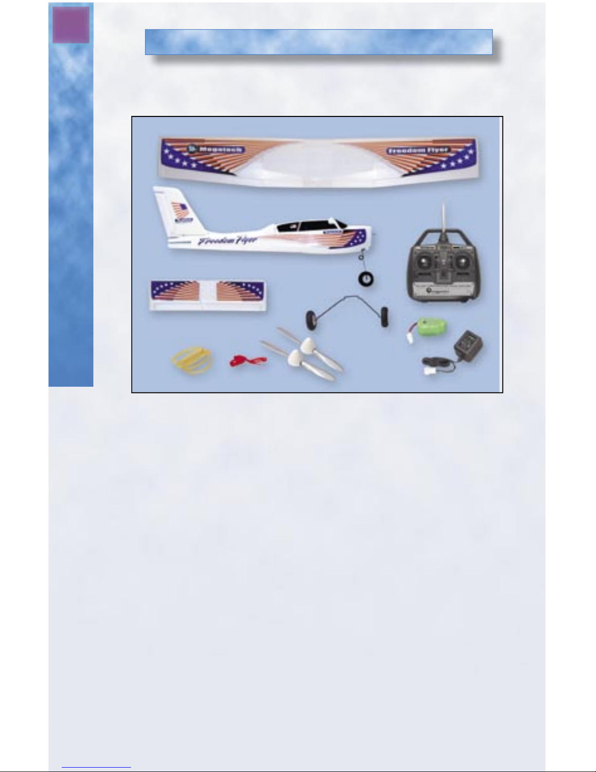
Review the components of the Freedom Flyer to ensure that your kit is
complete before you begin fi nal assembly. (See Figure 1)
Figure 1 – Exploded view of all parts
Kit Contents:
A. Main Wing
B. Fuselage – Includes Motor, Radio, Nosegear and Vertical Fin
C. 4-Channel Radio Transmitter
D. Horizontal Stabilizer with Elevator
E. Main Landing Gear
F. Rechargeable 8.4 volt Battery Pack
G. AC Adaptor/Battery Charger
H. Propellers with Nose Cone
I. Main Wing Bands
J. Wind Direction Tell-Tale
Make sure that you have received all parts shown.
If something is missing, call Megatech toll-free at 1-888-MEGA-911.
Page 5
5
Assembling the Freedom Flyer
Safety Warnings
The spinning propeller on this aircraft can be dangerous
and should be treated with respect and caution! Use
extreme care when operating your airplane. Keep your hands,
fi ngers and any article of clothing away from the propeller.
This model is designed to be fl own only in calm conditions (wind
speeds of 10 mph or less). Attempting to fl y your aircraft in winds
above 10 mph will result in a crash!
Assembling Your New Freedom Flyer
Items Required to Complete Your Freedom Flyer:
• 8 AA alkaline batteries
• Transparent tape
• Felt-tip marker
• Small Phillip’s Head screwdriver
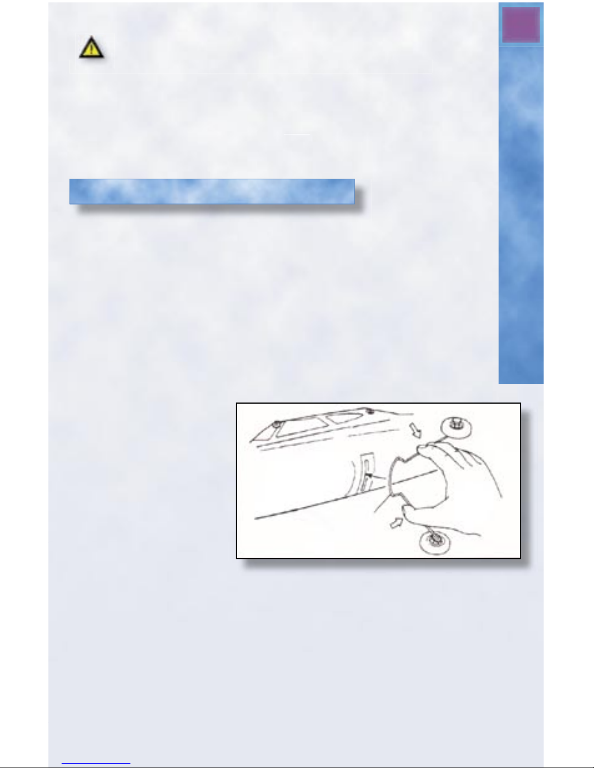
Step 1: Assemble the Landing Gear
Grasp the legs of the main landing gear. Gently squeeze the legs
together, and then push the gear into the slot on the bottom of the
fuselage. See Figure 2.
Press fi rmly, but gently,
until it is in all the way.
Then release the pressure
on the gear legs and give
them a gentle tug to make
sure they are secure. To
remove the main gear,
simply squeeze the gear
legs together to release the
gear from the housing and
pull it out of the slot.
Step 2: Assemble the Tail Surfaces
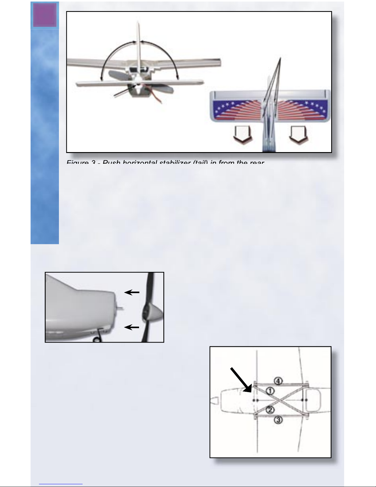
Locate the horizontal stabilizer from your kit. Remove the tape backing
and carefully slide the horizontal stabilizer into the slot located at the rear
of the fuselage as shown in Figure 3. The elevator control horn should be
pointing upward. Route the antenna under the horizontal stabilizer, so it
exits from the indentation in the rear of the fuselage. Make certain that the
stabilizer is perfectly level and 90 degrees to the vertical fi n as indicated in
the picture. When the horizontal stabilizer is properly aligned, use a small
Figure 2 - Squeeze legs until gear fi ts into slot.
Page 6
6
Assemble the Tail Surfaces
Figure 3 - Push horizontal stabilizer (tail) in from the rear.
Apply
tape
here.
90°
90°
Antenna should
exit here.
Insert
screws
here.
Phillip’s head screwdriver and insert the screws into the pre-drilled
holes in the tail as shown in Figure 3. Be careful not to over-tighten
the screws.
Next, snap the plastic control links into place. The clevis (hook) at
the end of the push rod on the left side of the plane (when held nose
down) attaches to the horn on the rudder. The clevis on the right
connects to the elevator control horn. Don’t worry if the rudder and
elevator are not straight. They will be adjusted later.
Step 3: Attach the Propeller
Find the propeller with built-in nose
cone. Firmly, but carefully, press it onto
the prop shaft at the nose of the plane
as shown in Figure 4.
Step 4: Attach the Wing to the
Fuselage
A. Set the wing on the fuselage.
Carefully align the center of the
wing onto the saddle area of the
fuselage. Look at the picture on
the box if you’re not sure what is
the front and what is the back of
the wing.
Figure 4 - Gently push nose cone
onto propeller shaft.
Alignment Marks
Figure 5 - Attaching the Main Wing
Page 7
7
The Radio System
B. Find the four wing bands. Hook the fi rst wing band over the
left rear post on the fuselage, then run it diagonally across the
wing and secure it to the right front post. Now repeat on the
other side. Right rear post to left front post. Then run a third
wing band from the left front to the left rear post and next run
a band from right front to right rear. See Figure 5.
C. After the wing bands are installed, check the wing once again
to make certain that it is still perfectly centered. When
perfectly centered, make an alignment mark (use a pencil
or felt-tip marker) at the front and rear of the wing where it
meets the fuselage. The marks will make it easier to align the
main wing next time you install it.
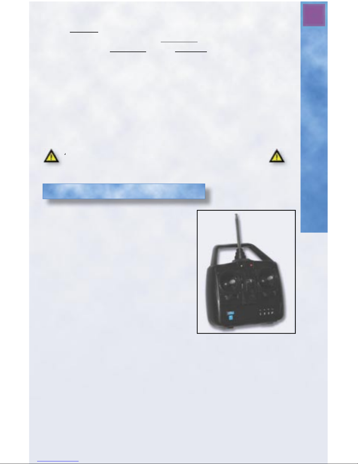
This aircraft includes a 4-channel R/C
(radio control) system although only 3
channels are actually used . See Figure 6.
The stick on the left side of the
transmitter operates the motor. When
this stick is all the way in the “down”
position, the motor is off. For added
safety, power won’t turn on until
after the stick is moved at least
halfway up. Then power increases as
the stick is moved up. Full power is
reached when the left stick is
positioned fully “up”. The right stick
controls the elevator (up and down)
function and the rudder (right and
left) function.
There are two battery LED lights located at the center top of the
transmitter face. When both the Red and Green lights are lit, you have
adequate power to control your aircraft. If only the Red light is lit, the
transmitter batteries are low and must be replaced. Never attempt to fl y
when only the red LED light is lit! This will result in loss of control and
most likely a crash! The radio system is tuned to a specifi c frequency
channel in the 27 MHz or 72MHz band. The crystals in both the transmitter
Figure 6 - The Radio Transmitter
Important Note!
Always remove the wing from the fuselage when not
flying. This will help reduce the chance of
accidental damage.
Always remove the wing from the fuselage when not
The Freedom Flyer Radio System
Page 8
8
The Battery Pack
and receiver may NOT be changed. Attempting to do so is a violation
of FCC (Federal Communications Commission) law and will render
your radio unusable! Contact our service center if you think there
may be a problem with your radio or should you need to change the
frequency. There is an auto-shutoff feature in the aircraft that allows
both the radio system and the motor to be powered from the same
battery pack. When the battery pack starts to run low, it will
automatically shut off the motor, while leaving enough reserve
power for the radio (about 3-4 minutes) to control the servos and
glide in for a safe landing. Land the plane as soon as possible when
the power runs out.
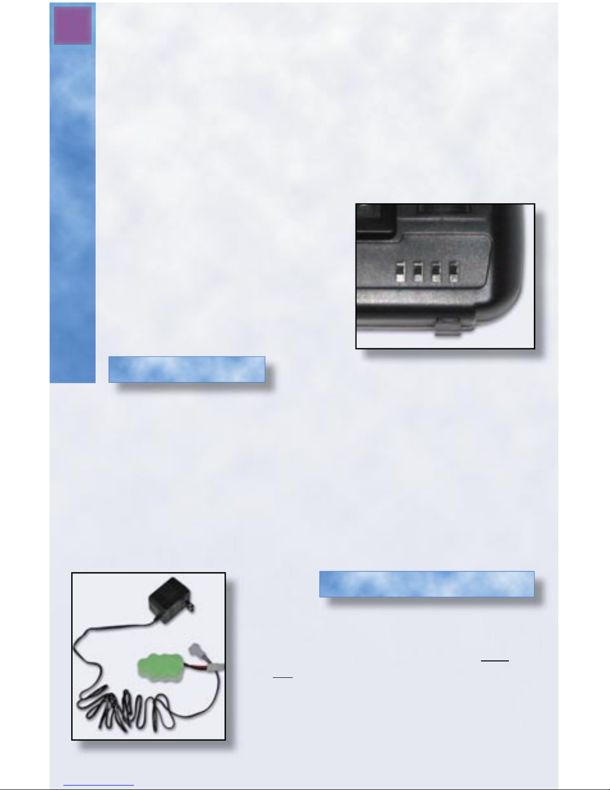
NOTE: The four switches at the
bottom right of the transmitter are
Servo Reversers. They enable this
transmitter to work with other RC
Aircraft. They are factory preset to the
correct position.
The Battery Pack
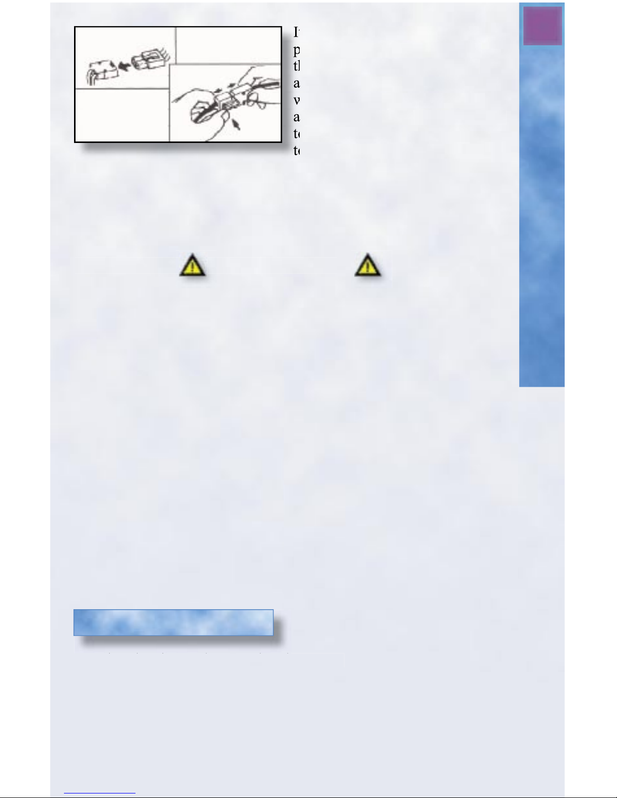
The battery pack included with the Freedom Flyer (see Figure 8) is made
up of NiMH (nickel-metal-hydride) rechargeable cells. These are very
different from regular dry cell batteries! With proper care and charging
methods, these packs can be charged and used hundreds of times before
they need to be replaced.
Important: The Freedom Flyer uses a special battery with polarized
connectors. Do not use any battery pack for this aircraft other than
original Megatech™ equipment. Use of any other battery pack may
cause damage to the aircraft and void your warranty!
The battery charger (see Figure 8) is
designed specifi cally for the battery
packs in your Freedom Flyer and will
not charge any other type of battery pack.
Attempting to charge a battery other than
the type included with this airplane will
result in damage to both the charger and
the battery.
The Battery Charger
The battery charger (see
designed specifi cally for the battery
packs in your Freedom Flyer and
Attempting to charge a battery other than
the type included with this airplane will
result in damage to both the charger and
the battery.
Figure 8 - Battery Pack and Charger
Figure 7 - Servo Reversers
Page 9
9
Charging the Battery
It is normal for NiMH battery
packs to become warm during
the charging process. You can
also expect the battery pack to be
warm after each fl ight. Always
allow a warm battery to cool prior
to recharging, and never attempt
to charge a battery pack that is
too warm to hold in your hand.
Always disconnect the charger from the electric socket when the
charging process is complete. When connecting or unplugging the
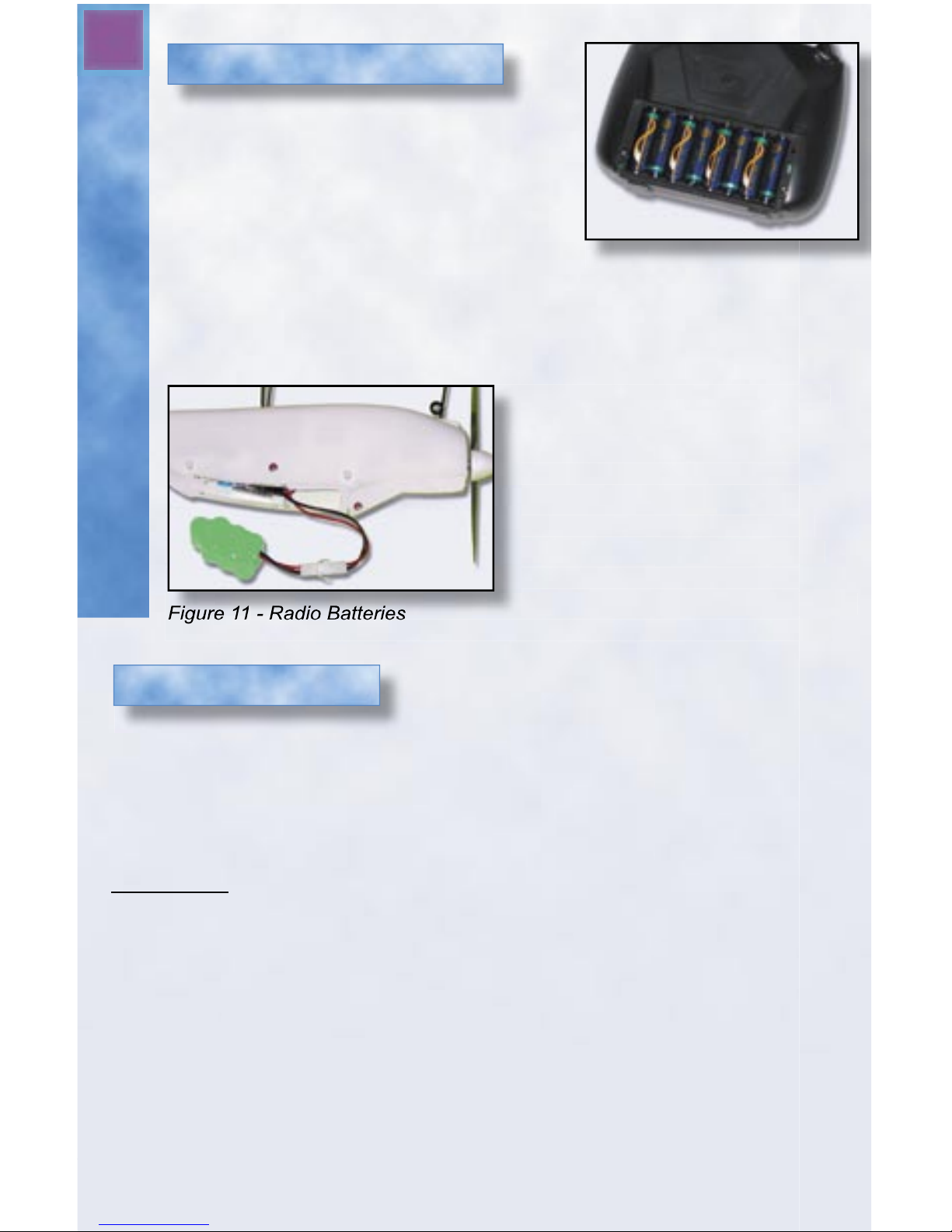
battery pack, hold it by the connectors. Never pull on the wires. (See
Figure 9)
CAUTION
READ THIS SECTION BEFORE CHARGING YOUR
BATTERY PACK FOR THE FIRST TIME!
● Always handle the battery pack carefully.
● Never cut the battery lead wires.
● Do not insert any metal objects into the battery plug, as a direct
short (and quite possibly a fi re) will result.
● Always remove the battery pack from your Freedom Flyer after each
fl ight. Do not store the battery pack inside the aircraft.
● Never allow the battery pack to get wet. Should the battery ever come
into contact with any moisture, dry it carefully before attempting to use
it again. Moisture can cause short-circuits and severe damage.
● Keep the battery away from heat or fi re. Never leave the battery pack
in direct sunlight.
● Never leave the battery pack unattended while charging. Over-charging
can damage your battery.
● Always remove battery from airplane before charging.
● Dispose of NiMH (nickel-metal-hydride) batteries properly. Never
place them in a fi re!
A. Plug the charger into an electric socket.
B. Next attach your battery pack to the battery charger. The charger will
automatically begin charging the battery pack.
C. Charging will take approximately 2 hours, however, longer charge
times may be necessary when the battery is new. Charging is complete
when the battery is warm to the touch. Do not allow the battery to get
too hot.
Charging the Battery
to charge a battery pack that is
It is normal for NiMH battery
packs to become warm during
the charging process. You can
also expect the battery pack to be
warm after each fl ight. Always
allow a warm battery to cool prior
to recharging, and
Figure 9 - Battery Connectors
Page 10
10
A. Be sure that both the transmitter and
receiver switches are in the “off”
position.
B. Install 8 fresh AA alkaline batteries
in the transmitter (see Figure10). Turn the
transmitter on to make sure both LED
lights glow. Fresh batteries will provide
about 2 hours of power to the transmitter. When the LED light glows
red, immediately install fresh batteries. Failure to do so will result in
loss of control and (most likely) a crash.
C. Charge the on-board battery
pack as previously instructed on
page 9.
Connect the charged battery as
shown in Figure 11. Carefully
install the battery between the
foam braces, neatly folding the
wires on top of the pack. Once the
battery is inserted into the aircraft,
the wing may be attached to the
aircraft.
Figure 10 - Radio Batteries
Figure 11 - Radio Batteries
pack as previously instructed on
shown in
AFTER READING THIS ENTIRE MANUAL, BUT BEFORE YOU
FLY YOUR FREEDOM FLYER FOR THE FIRST TIME:
You must “cycle” the battery pack at least twice prior to fl ying your
aircraft. This will provide the aircraft with more power and longer fl ight
times!
Here’s how: Switch on the transmitter fi rst. Charge the battery pack as
instructed earlier and then install the charged battery into the aircraft.
Carefully hold the airplane at the center of the fuselage so the propeller arc
is unobstructed and away from fi ngers, loose clothing, etc. Press the red
arming button and move the throttle stick to full. Allow the motor to run
until it stops. Allow the battery pack to cool, and then recharge. Repeat the
process of running the motor until the battery is drained. The battery pack
will now supply more power and your fi rst fl ights will be much easier and
safer!
Installing the Batteries
Cycling the Batteries
Installing & Cycling the Batteries
Page 11
11
Preparing to Fly
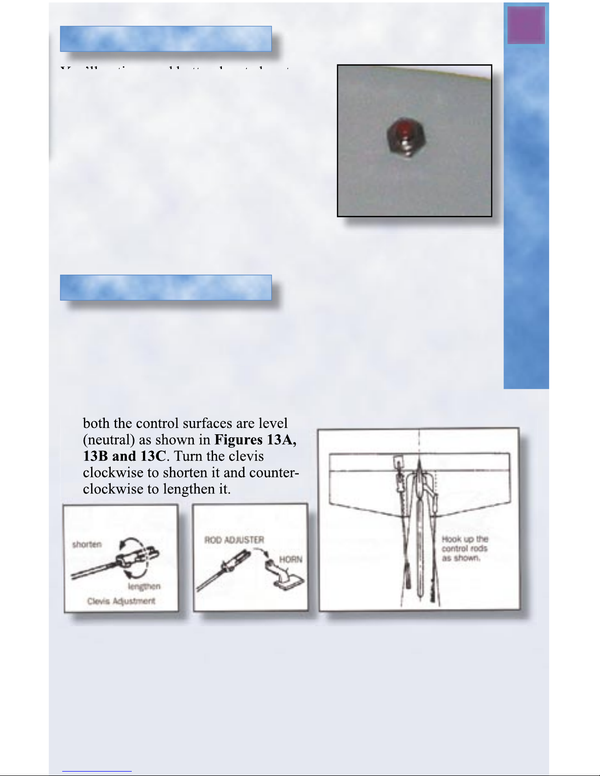
You’ll notice a red button located on the
side of the fuselage beneath the wing. This
button must be pressed before power can be
supplied to the motor. This safety start
switch exists so that radio interference or
problems can be discovered without the
motor starting unexpectedly. See Figure 12.
NOTE: Always turn the transmitter on fi rst,
before turning on the receiver. Only push
the red safety start switch after you are
certain that the radio is operating properly
and you’re ready to fl y!
A. Set the transmitter trim adjustment levers (located beside and
below the stick assemblies) to their center positions. Make sure the
throttle stick is in the “down” position! Turn on the transmitter.
DO NOT PUSH THE SAFETY START BUTTON AT THIS
TIME! Adjust the control links (clevis) at the end of the elevator
and rudder pushrods, so that when inserted into the control horns,
both the control surfaces are level
(neutral) as shown in Figures 13A,
13B and 13C. Turn the clevis
clockwise to shorten it and counter-
clockwise to lengthen it.
Safety Start Switch
Figure 12 - Safety Start
Switch
Preparing to Fly
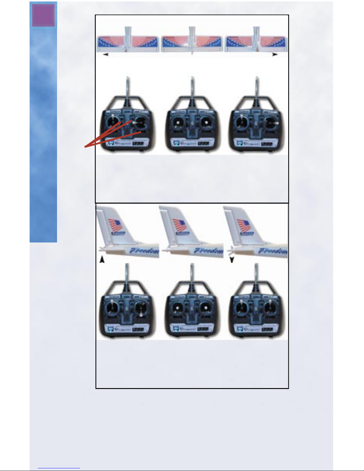
B. At this time, move the rudder and elevator control stick (the right con-
trol stick), to see how the controls operate your Freedom Flyer. Notice
that you can operate the rudder and elevator at the same time. This helps
provide smooth, controlled fl ights. See Figure 14 for reference.
both the control surfaces are level
(neutral) as shown in
13B and 13C
clockwise to shorten it and counter-
clockwise to lengthen it.
Figures 13A,
Figure 13A Figure 13B Figure 13C
Page 12
12
By moving the stick diagonally, you can turn the plane and change
altitude at the same time. The control stick is proportional, so if the
movement of the stick is more to the right than down, for example, the
plane will bank strongly to the right, but ascend gradually or hold
altitude. When the plane banks left or right, the nose will tend to drop,
Center the trim
controls and
sticks. Then
adjust the
pushrods so the
rudder is straight.
Move the stick left
and the rudder
moves left. This
causes plane to
turn left.
Move the stick
right and the
rudder moves
right. This causes
plane to turn right.
Trim
Controls
Move the stick up
and the elevator
moves down. This
causes plane to
descend.
Center the trim
controls and
sticks. Then
adjust the
pushrods so the
elevator is level.
Move the stick
down and the
elevator moves
up. This causes
plane to ascend.
Up Neutral Down
Figure 14 - Control Stick Movements
Left Turn Neutral Right Turn
Rudder and Elevator Control
Page 13
13
Safety Precautions
so a little up elevator will tend to keep the plane from dropping.
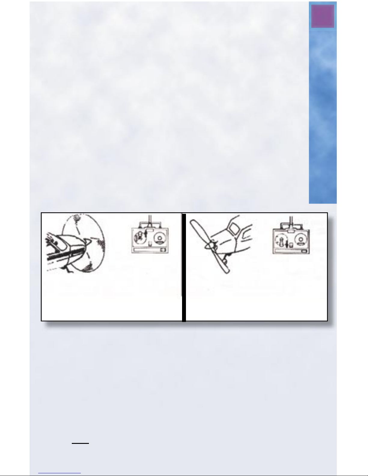
C. Next test the motor (this should be done outdoors!). First, make
certain that the left stick, the throttle stick, is in the “off” position (all the way down) and the transmitter switch is on. Then
fi rmly grasp the center of the Freedom Flyer fuselage, keeping
hands and all obstructions clear of the propeller. Now press the
red safety start switch and slowly move the throttle up to full to
make certain the propeller and gearbox are operating properly.
Move the throttle up and down a few times to get a feel for how
it works (See Figure 15). Once you are satisfi ed and familiar
with the operation of your Freedom Flyer, unplug the battery and
then turn off the transmitter.
IMPORTANT:
Always turn on the transmitter fi rst (before installing the
battery).
Always unplug the battery fi rst (before turning off the
transmitter).
IMPORTANT SAFETY PRECAUTIONS
Please read these before operating your Freedom Flyer.
● You alone are responsible for operating your aircraft in a safe and
responsible manner. Follow these basic safety guidelines at all times.
● Always fl y your airplane in a wide-open area. You’ll need at least
two football fi elds worth of area that is free from obstructions such as
buildings, electric power lines, trees, roads, other people or vehicles.
Do not fl y around people who are unaware that you are fl ying a model
airplane, and never fl y over people’s heads.
● Fly only on calm days. Gusty winds and winds over 10 mph will make
it diffi cult (if not impossible) to control the aircraft properly.
When the motor
stops running, the
plane glides.
Move the stick up to turn
the motor on and the
propeller starts turning.
The more you move the
stick up, the faster the
motor will run. Move the
stick fully up for maximum
speed.
Your airplane runs
forward at variable
speeds.
Move the stick fully
down to turn the
motor OFF and the
propeller will stop
turning.
Figure 15 - Throttle Stick Movements
Page 14

14
● Make sure that the transmitter and receiver are both switched off
and the battery is disconnected when you are not fl ying.
● Do not attempt to disassemble any of the airplane’s components or
allow them to get wet. Electrical damage may occur.
● Never fl y your airplane from roadways or after dark.
● When operating/fl ying, always be aware of the spinning propeller.
Be careful not to let it come close to your body, other people or
loose clothing.
● Keep spectators behind you when fl ying.
● Since your airplane is controlled by a radio link, it is very
important to always use fresh alkaline batteries in the transmitter.
We recommend Megatech’s Golden Power series, designed for
R/C products.
● Before fl ying, make sure you perform a range check and can
maintain control at least 25 feet from transmitter to model with the
transmitter antenna collapsed. Do not fl y your airplane if
other models are being operated on the same frequency in the area.
If you are at a fi eld with other pilots, NEVER TURN ON YOUR
TRANSMITTER OR RECEIVER without fi rst confi rming that
there are no other models in the air on the same radio frequency.
Talk to the other pilots and make sure that they are aware of what
frequency you are using.
● Do not use solvents or liquid cleaners to clean this model. Doing
so may damage the plane. Use a dry, soft cloth for cleaning.
Pre-Flight Preparations
Now it’s time to describe how you can become a successful R/C pilot with
the Freedom Flyer. A little patience and care exhibited here will result in a
well-fl ying, long-lasting aircraft.
Did you “cycle” the battery pack as previously described on page 10? This
is extremely important!
Perform these pre-fl ight checks each time you fl y:
● Is the wing properly aligned and attached securely to the fuselage?
● Are both transmitter LED lights glowing?
● Is the transmitter switched on prior to installing the battery pack?
● Do the rudder and elevator controls work properly after turning on the
transmitter?
Pre-Flight Preparations
Page 15
15
Your First Flight
We recommend that while learning, you launch your Freedom Flyer
by hand. Although capable of taking off from the ground, there are
several
disadvantages to attempting this. Ground take offs provide no margin
for error. After breaking ground, you simply do not have enough time
to react to sudden changes in pitch or altitude. With a hand launch,
the Freedom Flyer will basically “fl y out of your hand,” providing
several feet of altitude for the airplane to stabilize prior to needing
any control inputs. This gives you a few precious seconds to catch
your breath and begin controlling the aircraft. We strongly recommend using only hand-launch take offs when learning to fl y the
Freedom Flyer.
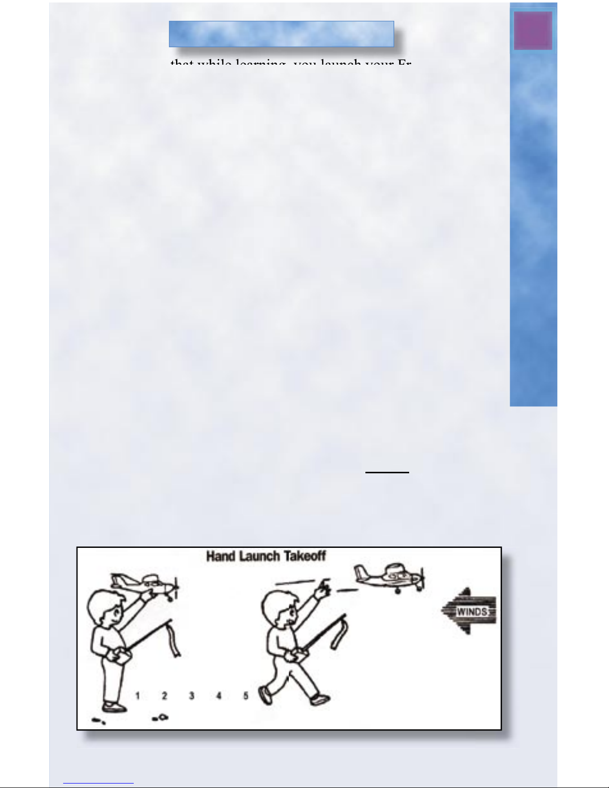
Launching By Hand
1) Face directly into the wind.
2) Turn on the transmitter fi rst, and then install the battery.
3) Grip the aircraft underneath the fuselage and slightly
behind the wing. Press the red safety start button.
4) Move the throttle stick up to full power.
5) Take 4 or 5 running steps, keeping the wings as level as possible
with the aircraft pointed into the wind. You’ll feel the airplane
actually try to rise up out of your hand.
6) Give the plane a fi rm, level push forward as you run (in a
smooth motion). Do not throw the airplane! Release the
airplane straight and level with the ground. Do not release it
with the nose pointed upward. The plane will begin to climb
upon release. See Figure 16.
Your First Powered Flight
Figure 16 - Hand Launch
Page 16
16
Turning Your Plane
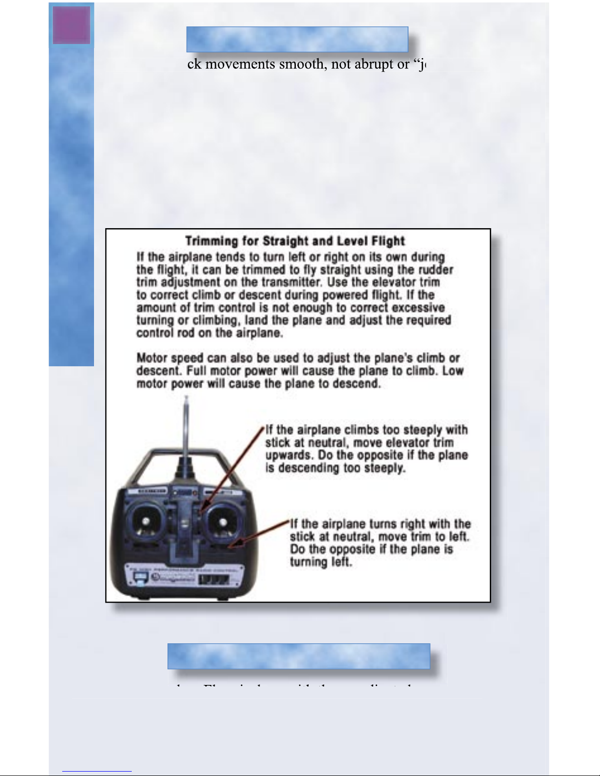
Keep your stick movements smooth, not abrupt or “jerky”. The
aircraft will actually fl y all by itself if left alone, and SMALL movements of the stick are all that you need to control your plane. In fact,
moving the rudder/elevator stick all the way in any direction will
cause the aircraft to become unstable, so remember……smooth!
After launch, allow the aircraft to fl y directly away from you and
gain altitude prior to making your fi rst turn. If the aircraft turns,
climbs or dives with no control input, correct the fl ight path by gently moving the stick in the appropriate direction. See Figure17.
Control Stick Adjustments
Turning the Freedom Flyer is done with the coordinated use of both
rudder and elevator controls. The rudder makes the aircraft yaw (bank)
in the direction you wish to turn. When the aircraft banks, the nose will
naturally drop, so small amounts of up elevator will be needed to keep the
aircraft at a constant altitude while turning. As the aircraft turns to the new
heading that you desire, a small application of opposite rudder will level
the wings and return the aircraft to straight and level fl ight.
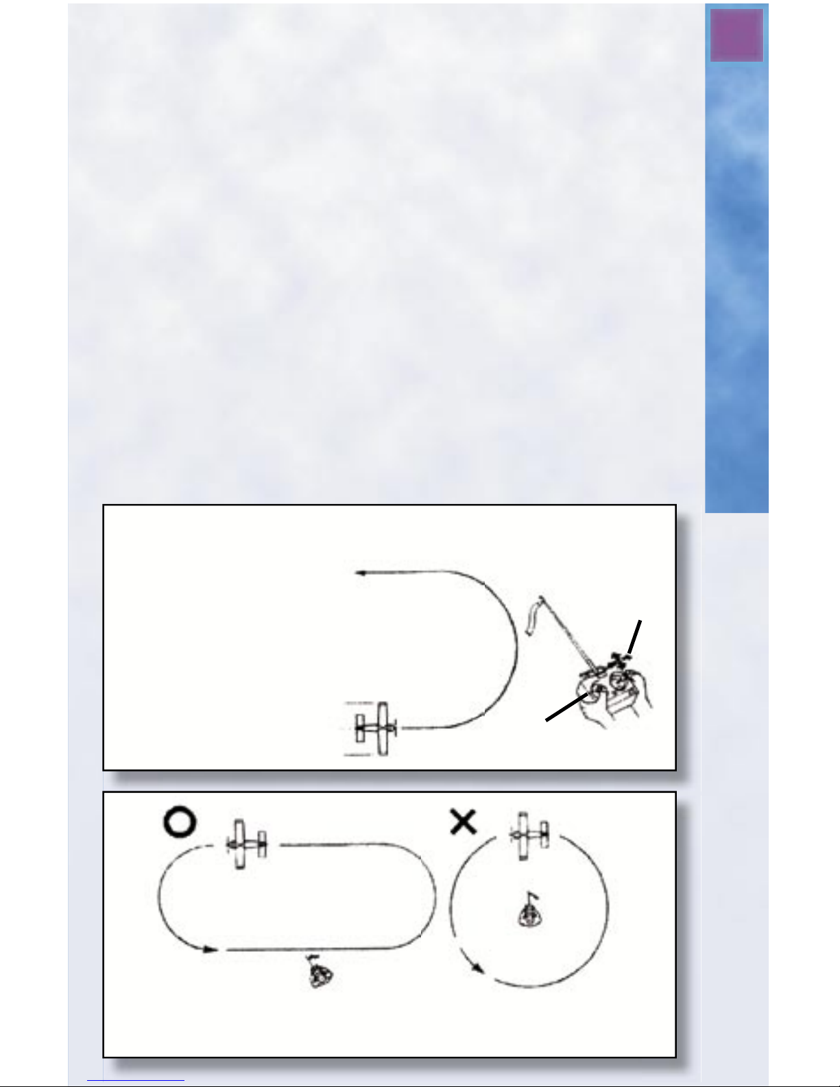
For your fi rst fl ights, you’ll fi nd it easier to turn by making two 90-
degree turns instead of one 180-degree turn. Turn 90 degrees, fl y straight
for awhile and then make another 90-degree turn. Do not attempt to make
a complete circle, as it’s easy to become disoriented. See Figures 18A and
18B.
Start the turn by feeding in a small amount of rudder in the direction you
wish to turn. As the airplane turns and the nose drops, gently feed in just
enough up elevator to keep the nose level. Bring the rudder back to neutral
as the aircraft completes the turn. When on the desired heading, feed in
just a bit of opposite rudder to level the wings and return the elevator to
neutral to keep the aircraft from climbing excessively.
Your fi rst fl ights will be easier if you face the same direction your air-
craft is fl ying. This way, you can always orient yourself as if you’re in the
pilot’s seat, even if it means looking back over your shoulder at the plane.
NOTE: if the airplane is fl ying directly at you, the rudder control direction
is “reversed”. This means that right stick results in a turn toward your left
Figure 17- Adjusting the Trim In Flight
Turning Your Freedom Flyer
Page 17
17
Adjusting the Trim
After you become experienced
at turning around by making
two 90-degree turns as
described earlier, you can
try turning in one smooth
continuous motion as shown
here. Remember that turning
a plane requires a coordinated
movement of both rudder and
elevator. Use the rudder control
to bank the plane into the turn,
and use the elevator control to
maintain altitude.
Practice, practice, practice!
Elevator &
Rudder
Stick
Motor
Stick
Figure 18A - Turning Your Aircraft
Fly an oval pattern in front of you as shown here on the left. Flying in a
continuous circle or fl ying around you as pictured on the right will lead to
disorientation and will most likely cause you to crash.
Figure 18B - Flying Pattern
Page 18

10
Limited WarrantyIn Case of Trouble
18
when the aircraft is fl ying toward you. Turning with the plane and
always facing the same direction will greatly help you learn how to
fl y in a shorter period of time.
During the fi rst fl ight, execute gentle climbing circles in front of you.
Keeping the aircraft in front of you (not overhead) is very important
and crucial to successful fi rst fl ights. Fly the airplane at a comfortable altitude and wait for the motor to cut off. Always think about
where you want the airplane to go next. Anticipate where you want
the aircraft to be prior to bringing the aircraft in for a safe landing.
Having trouble?
Should you over-control your airplane or lose orientation, it’s possible that you’ll fi nd yourself in a downward spiral dive. Should this
occur, remain calm and simply release the sticks! The plane will stop
turning by itself, and will exit the spiral dive with the nose pointed
down. Feed in some up elevator to level the aircraft and climb to a
safe altitude.
If you see that you’re going to crash, immediately cut the power.
Doing so will minimize the damage to the aircraft.
Page 19
19
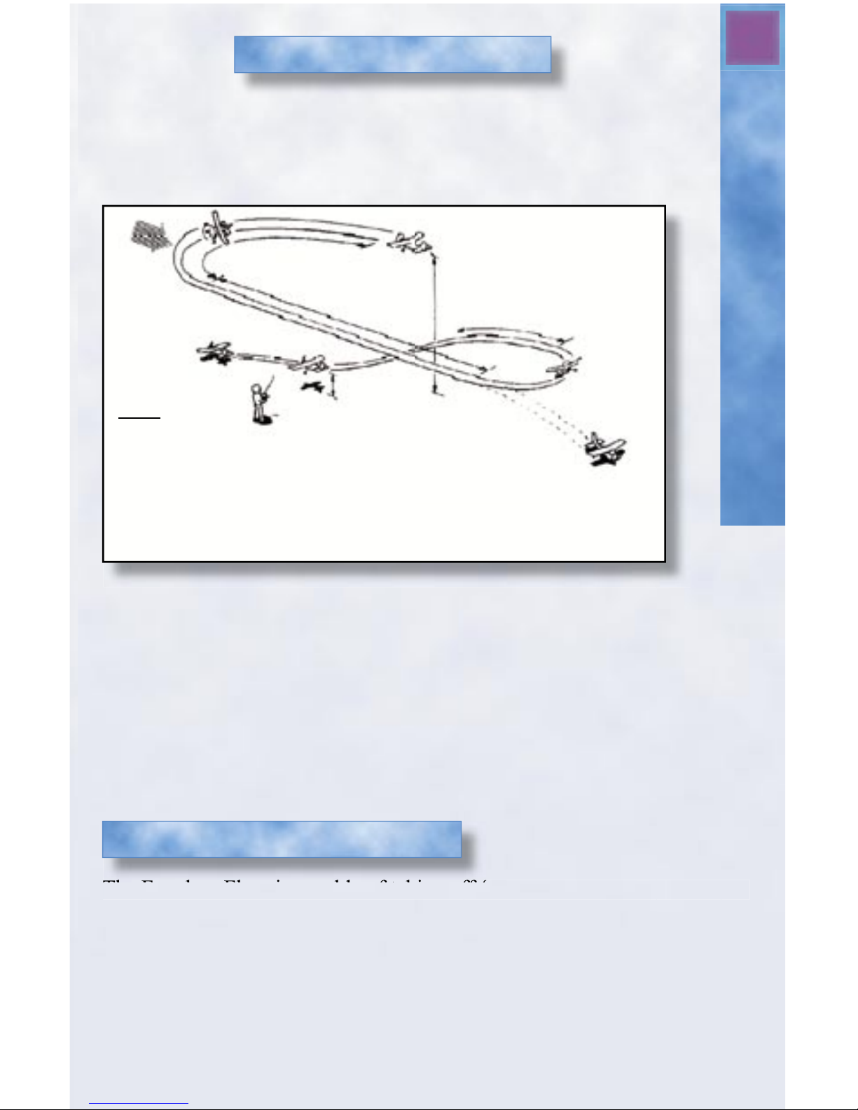
When the motor stops, the nose will drop slightly. This is normal
under reduced or zero power. Do not immediately give up elevator!
Use the rudder to steer the aircraft toward a landing pattern. (See
Figure 19)
Landing Your Freedom Flyer
Note:
When the
motor shuts off,
slide the motor control
stick down to the off position.
This will prevent the motor
from unexpectedly coming
back on.
If the airplane is too low, a
downwind landing may be
required.
Circle the airplane
gradually into the
direction of the wind.
Figure 19 - Landing Your Aircraft
Always set up landings into the wind, and use very small amounts of up
elevator during turns. You should keep the nose of the plane in a gentle
dive to maintain forward airspeed when the motor is off. At an altitude of
about 3 feet, gently pull back on the elevator to “fl are” the aircraft (point
the nose slightly upward) before touchdown.
If you’re too far away to land safely on the desired landing area, don’t
panic! Simply land the plane smoothly into the wind. You will not damage
the aircraft as long as you take care to land gently!
The Freedom Flyer is capable of taking off from the ground. Keep in mind
that ROG (rise off the ground) take-offs use up some battery power and
will shorten your fl ight time.
The most important thing to remember about lifting off from the ground is
to gently apply up elevator after the airplane has reached suffi cient fl ying
speed. Excessive elevator input will cause the aircraft to stall and fall out
of the air, as will trying to lift off before suffi cient airspeed is built up.
Taking Off From The Ground
Landing Your Plane
Page 20
Repairing your Freedom Flyer
20
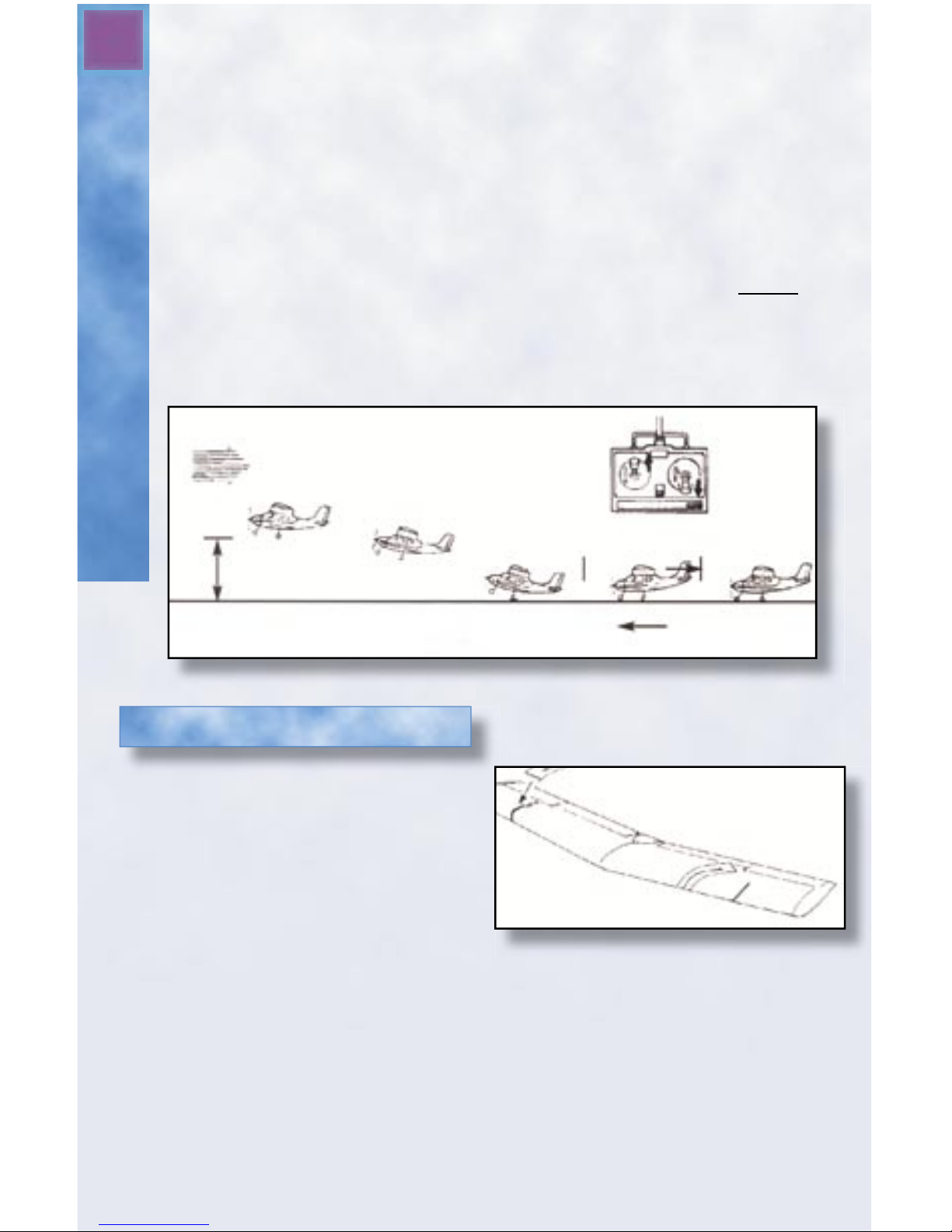
Begin by placing the airplane on a smooth asphalt or concrete surface. Push the aircraft by the vertical fi n and watch to make sure that
it rolls straight. If the airplane pulls to the right or left, adjust the
nose wheel so that it rolls straight down the runway. Once the aircraft rolls straight, line it up on the runway that you’ll be using and
you’re ready to attempt a ground take off.
Switch on the motor and advance the throttle to full power. Keep the
airplane travelling in a straight path by using small rudder inputs if
necessary. Allow it to pick up speed for about 35 feet, then gently
add a small amount of up elevator and the Freedom Flyer will break
ground. Continue to gain altitude in a shallow climb and you’re on
your way. See Figure 20.
30'
60'
Elevator up gently
Wind
Figure 20 - Taking Off From The Ground
Making Repairs
If the wings or tail surfaces should
crack or break, they can be repaired
using 5-minute epoxy glue. If the
crack is small, the part can also be
fi xed using a strong clear packaging
tape. See Figure 21.
Installing a New Propeller
When it is time to replace the propeller, fi rmly, but carefully, pull
the current propeller and nosecone off. Then, slide the new
nosecone and propeller into place.
Figure 21 - Repairing the Wings
Page 21

21
Spare Parts
Spare, repair and replacement parts are readily available for your aircraft.
Should you need parts, visit your local hobby dealer fi rst. If unavailable,
you may order directly from Megatech. Use this sheet as a guide.
Part Number Description
MTC 994101 MAIN WING
MTC 994102 TAIL WING SET(RUDDER & ELEVATOR)
MTC 994103 FUSELAGE(NO MOTOR &ELECTRONIC PARTS)
MTC 994104 LANDING GEAR SET
MTC 3959 8.4V 900MAH NIMH BATTERY
MTC 994105 AC CHARGER (PLANE)
MTC 1418 8.4V 10AMP SPEED CONTROL
MTC 994106 MOTOR(380)
MTC 1416-X 27MHz RECEIVER (SPECIFY CH. 1-6)
MTC 1419 72MHz RECEIVER
MTC 7320-X PF4000 27MHz TRANSMITTER (SPECIFY CH. 1-6)
MTC 7321 PF4000 72MHz TRANSMITTER ONLY
MTC 994108 PUSHROD
MTC 994109 CLEVIS
MTC 994110 WING HOLDDOWN
MTC 202 SERVO(9G)
MTC 3841 DC PEAK CHARGER (PLANE)
MTC 202-01 ARM FOR SERVO
MTC 732001-X 27MHz CRYSTAL SET (1 TX & 1 RX, SPECIFY CH 1-6)
MTC 732101-X 72MHz CRYSTAL SET (1 TX & 1 RX, SPECIFY CHANNEL)
MTC 994112 COMPLETE DECAL SET
Telephone Orders: (201) 662-2800
Fax Orders: (201) 662-1450
Obtaining Spare Parts
Page 22

ROG Take-Offs
Trouble Shooting Guide
22
PROBLEM POSSIBLE CAUSE SOLUTION
Motor/propeller does not move Battery not fully charged. Charge the battery.
after red button is pressed & Battery not connected Connect the battery
throttle moved. Properly. Correctly.
Motor moves when the start Battery is not fully charged. Charge the battery.
button is pressed, but stops when
the button is released.
Motor starts as soon as the batter Is something holding down Remove your fi nger
is connected. the red button? or obstruction from
the red button.
Motor only runs for a short time Battery is not fully charged. Charge the battery
before turning off. again following the
directions.
Rudder/elevator move erratically Transmitter batteries are Install fresh AA
with no input from the transmitter. low. batteries.
Transmitter antenna is not Extend the antennae.
fully extended.
Transmitter is too close to Move the transmitter
aircraft. away from the plane.
Battery is not fully charged. Charge the battery again
following directions.
Another radio is operating Wait until channel is
on the same channel. clear or the other radio
is off.
After launch, the plane does not Plane was improperly Review launching
fl y straight or crashes. launched directions.
Rudder or elevator are Make sure rudder and
not trimmed correctly. elevator are set to
neutral trim.
Tail is not securely Use clear tape to
mounted on the fuselage. secure the tail.
Battery is not fully charged. Charge the battery.
Using too much “up” Use less up elevator.
elevator.
Aircraft does not fl y straight, but Rudder is not at neutral. Recheck the trim &
turns left or right. adjust if needed.
The wing isn’t aligned Review instructions
properly. on aligning the wing.
Elevator isn’t aligned right. Check and align the
horizontal stabilizer.
Using too much elevator. Use small, gentle
control inputs.
Aircraft pitches violently up or Too much elevator Use small, gentle
down during fl ight. movement. control inputs.
Aircraft loses altitude rapidly Too much rudder being used. Use smaller inputs.
during turns. Not enough elevator being After applying rudder
used during turns. apply elevator to
maintain altitude.
Page 23

23
Limited Warranty
Megatech® International guarantees this item to be free from defects for a period of
90 days from date of purchase. If any component of this product fails to function
properly due to defects in materials or manufacturing process during this 90 day
period, the manufacturer’s obligations are limited and manufacturer can choose to
either repair or replace the item.
This warranty is void if the product in question has been altered or repaired by
anyone other than Megatech International or an authorized agent.
Under no circumstances will Megatech International or any of its representatives
be held liable for injury to persons or property damage resulting from assembly or
use of the product. Megatech is not liable if any outside radio frequencies interfere
with the product’s frequency causing loss of control. Megatech International will
not be held liable for any injury to persons or property damage resulting from an
out-of-control model caused by use or misuse of the product. Megatech International expressly excludes any and all express warranties not specifi cally stated here
and all implied warranties of merchantability and fi tness for a particular purpose.
There are no warranties which extend beyond the description of the warranties
contained herein.
Contact the Megatech International Service Department before returning any item
that is defective according to the limitations listed above. Please be sure to pack
the returned item(s) carefully. The customer must return the product along with
proof of purchase, a letter describing the problem and the customer’s address and
telephone number. At this point in time we will either repair the defective part or
replace it and return it to the customer. Return shipping and handling in the 48
contiguous states is $12.99. Shipping outside of the 48 states will be quoted by
location.
This warranty does not cover any damage caused by use, misuse, alteration, accident, or neglect, nor does it cover normal wear and tear of the product. Product
returned to us which falls under this category will be submitted to our service
department for repair. We reserve the right to charge any service and parts fees
incurred when repairing the item.
Megatech® International
8300 Tonnelle Avenue
North Bergen, NJ 07047
(201) 662-2800
www.megatech.com
eMail: info@megatech
Limited Warranty
Page 24
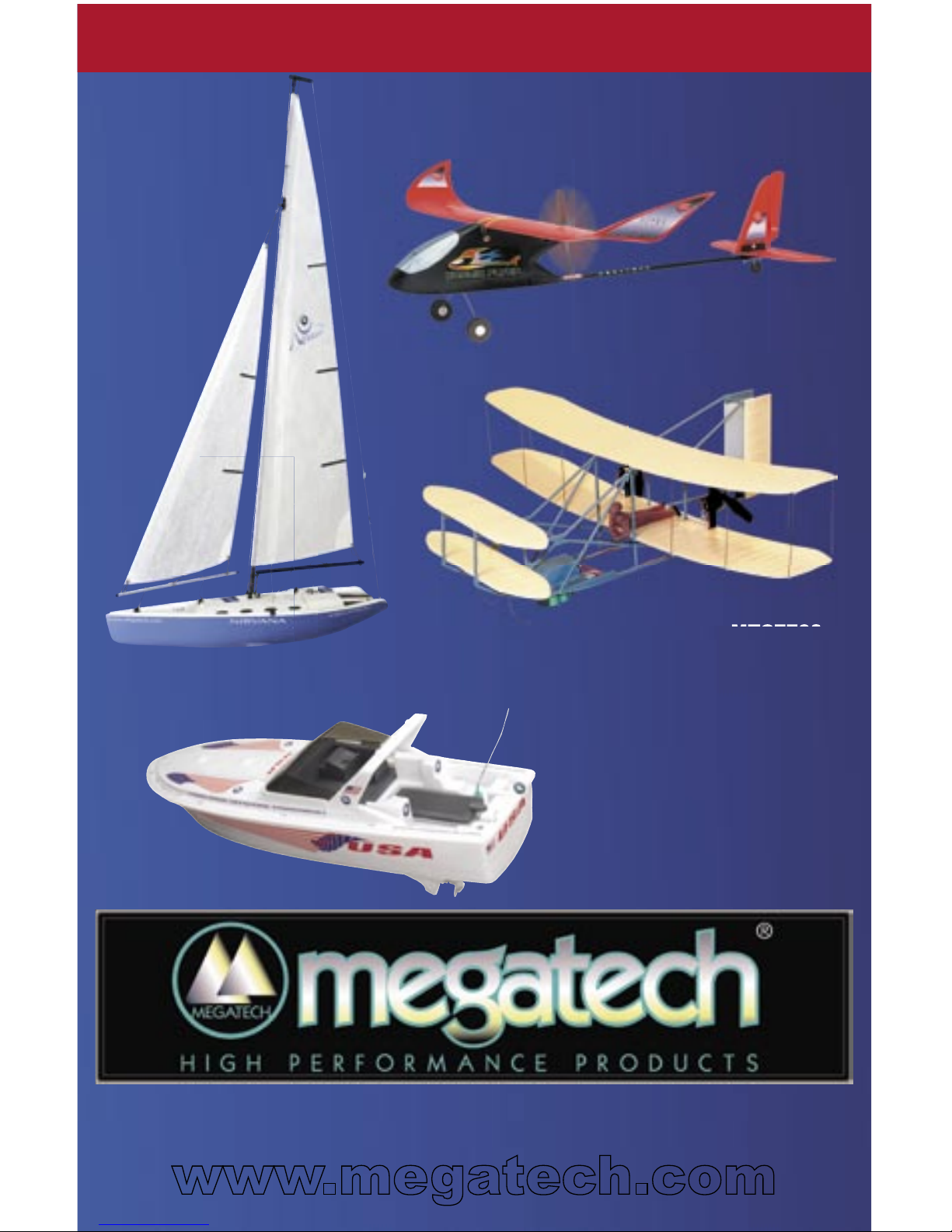
MTC6901
NIRVANA R/C RACING CLASS
SAILBOAT
LOOK FOR THESE OTHER FINE MEGATECH PRODUCTS
www.megatech.com
Megatech International - 8300 Tonnelle Avenue
North Bergen NJ 07047 - (201) 662-2800
MTC9932
COSMIC FLYER R/C EASY FLYER
MTC7703
WRIGHT FLYER R/C AIRPLANE
MTC6905
USA R/C CRUISER YACHT
 Loading...