

MegaTech Air Strike Instruction Manual

Entire contents © Megatech 2003
www.megatech.com
®

If you have questions about operating or installing your new Megatech
product, or if you are missing parts... Please Call Megatech First!
DO NOT RETURN THIS PRODUCT TO THE STORE
Call our Customer Service Department at:
(201) 662-2800
10:00am - 5:00pm, EST Monday through Friday (except holidays)
Technical assistance is also available on-line at www.megatech.com
or by e-mail to questions@megatech.com
Congratulations on your purchase of a Megatech® Air Strike®.
Flying has never been more fun! Get ready to launch into a new
world of high-fl ying excitement! Your new Air Strike® requires no
tools or glue to assemble and within minutes of opening the box,
it will be ready to soar at speeds up to 35 mph and reach amazing
heights. Then you simply recharge the fl ight pack and take off on
your new adventure.
Please read this entire manual carefully before you
attempt to build or fl y your Air Strike.
If you experience any problems, DO NOT take your Air Strike® back to
the store! Call one of our MegaTechnicians at 1-888-MEGA-911 or send
an e-mail to: info@megatech.com
2
Introduction
• Flight time is about 8-10 minutes. When the power on the plane is low,
the motor will shut off, however, the servos will still work, so you can
land. Land the plane as soon as possible when the power runs out.
• Bring several extra fl ight pack with you for longer fl ying time.
• 8 AA alkaline batteries are recommended for the transmitter.
• Check the direction and wind speed before each fl ight. Although the
AirStrike is capable of fl ying in winds of 10 mph, Megatech recommends
waiting for a day with little or no wind until you become familiar with the
fl ight characteristics of the plane.
• Check the power light on the transmitter before each fl ight. If the green
light becomes dark or goes out, Do not fl y. Change the batteries in the
transmitter.
• Always stay far away from trees, buildings and elevated land. Unexpected
air currents can quickly alter your Airstrike’s course and possibly lead to
a crash.
Helpful Hints

3
Table of Contents
TABLE OF CONTENTS
Getting Acquainted with Your Air Strike® ......................................4
Safety Warnings ..............................................................................5
Assembling the Main Wing ............................................................5
Assembling the Landing Gear ........................................................6
Assembling the Tail Surfaces ..........................................................7
Attaching the Wing to the Fuselage ................................................7
The Air Strike® Radio System .........................................................8
The Battery Pack .............................................................................9
The Battery Charger ......................................................................10
Charging the Battery ..................................................................... 11
Cycling the Batteries .....................................................................12
Installing the Batteries .................................................................12
Safety Start Switch ........................................................................13
Preparng to Fly ..............................................................................13
Rudder and Elvator Controls ........................................................14
Testing the Motor ..........................................................................15
Safety Precautions .........................................................................16
Pre-Flight Preparations .................................................................17
Your First Powered Flight .............................................................18
Launching By Hand ......................................................................18
Control Stick Adjustments ............................................................19
Turning Your Air Strike® ...............................................................20
Having Trouble .............................................................................21
Landing Your Air Strike® ..............................................................21
Taking Off from the Ground .........................................................22
Making Repairs .............................................................................23
Installing a New Propeller ............................................................24
Obtaining Spare Parts ...................................................................25
Air Strike® Trouble Shooting Guide .............................................26
Warranty Information ....................................................................27
4
Air Strike Kit Contents
Getting Acquainted with Your Air Strike
A
B
C
D
E
F
G
H
I
J
K
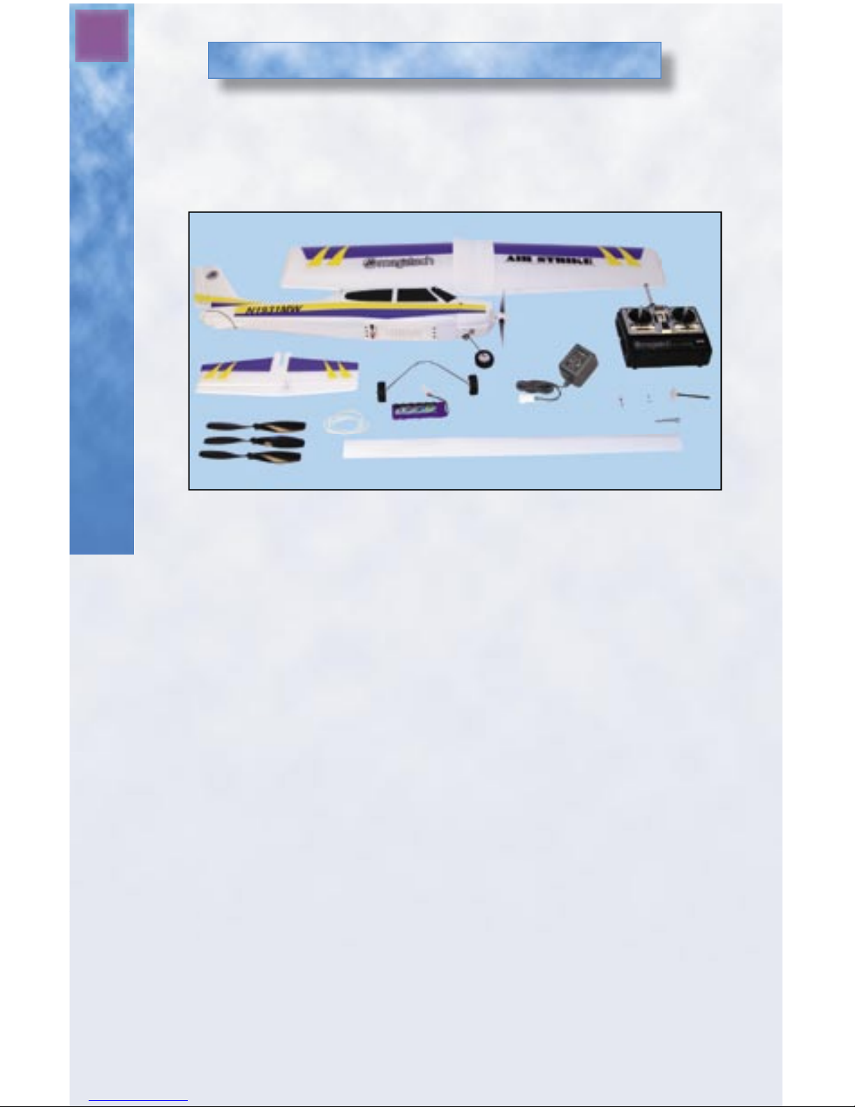
Review the components of the Air Strike® to ensure that your kit is
complete before you begin fi nal assembly. (See Figure 1)
Figure 1 – Exploded view of all parts
Kit Contents:
A. Main Wing
B. Fuselage – Includes Motor, Gearbox, Radio,Vertical Fin & Nose Wheel
C. 3-Channel Radio Transmitter
D. Horizontal Stabilizer with Elevator
E. Main Landing Gear
F. Rechargeable 8.4 volt Flight Pack
G. 110v Wall Charger
H. Spare Gear Shaft
I. Extra Propeller
J. Main Wing Bands and Spares
K. Spare Prop Nuts
L. Spare Fuse
M. Prop Wrench
N. PVC Tape Strip
Make sure that you have received all parts shown.
If something is missing, call Megatech toll-free at 1-888-MEGA-911
L
M
N
5
Assembling the Air Strike
Safety Warnings
The spinning propeller on this aircraft can be dangerous!
Use extreme care when operating your airplane. Keep your
hands, fi ngers and any article of clothing away from the propeller.
This model is designed to be fl own only in calm conditions (wind
speeds of 10 mph or less). Attempting to fl y your aircraft in winds
above 10 mph can result in a crash!
Assembling Your New Air Strike
Items Required to Build Your Air Strike®:
• 8 “AA” alkaline batteries
• Transparent tape
• Felt-tip marker
Step 1: Assemble the Wing
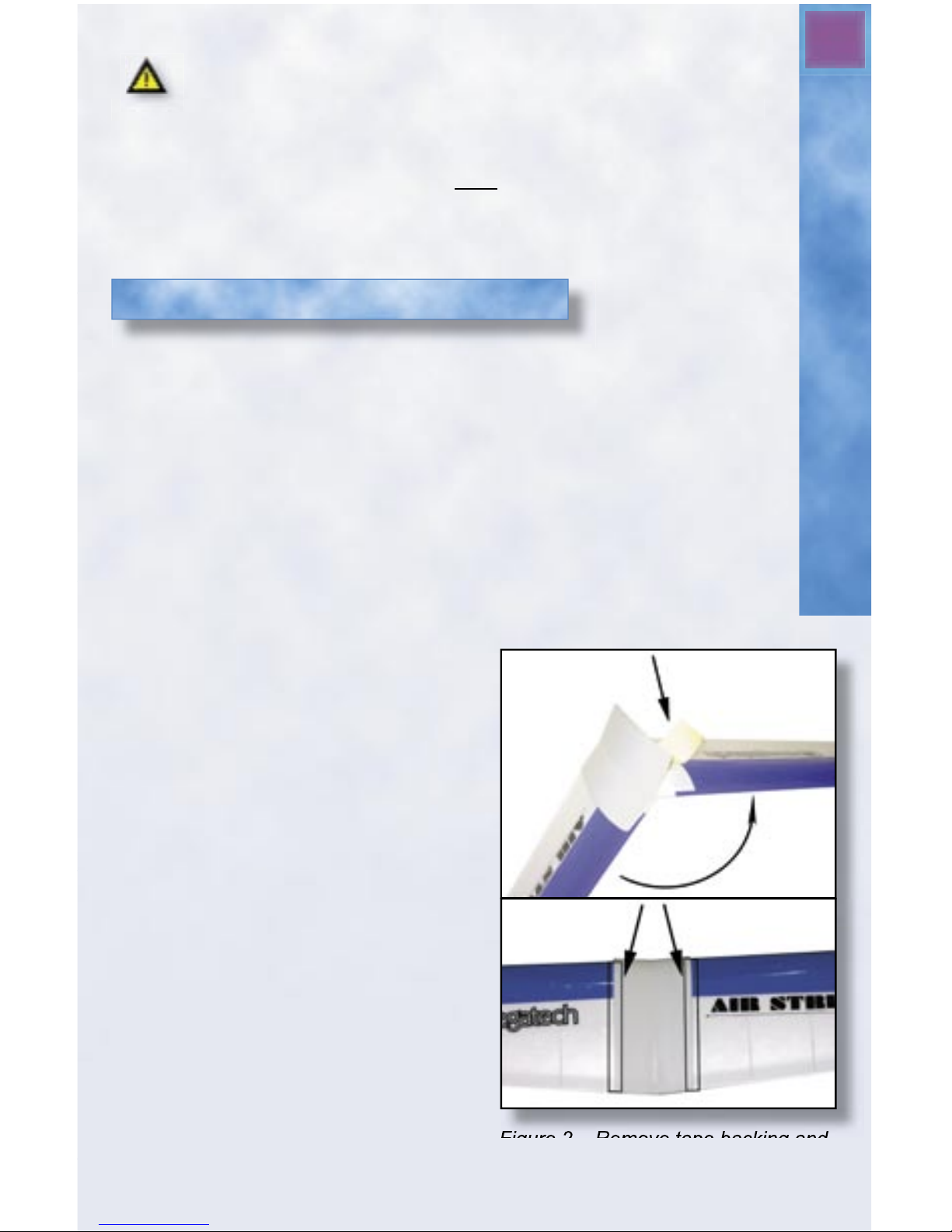
A. Locate the main wing. Remove the backing material from the
double-sided tape located on top of the wing’s center section. Now,
unfold the wing so that the plastic center section is securely adhered
to both wing panels. See Figure 2A.
B. Cut 4 strips of clear tape
(Scotch® tape or equivalent) to
a length of 7" (177mm) each.
Tape strips should be applied to
the wing where the center section
ends on the top and immediately
below this on the bottom.
Apply the tape to the bottom
of the wing fi rst, then the top.
Make sure the tape strips on
top of the wing are half on
the plastic center section and
half on the foam wing surface.
The tape will help to protect
the wing against dents and
damage from the wing
bands that hold the wing to the
fuselage. See Figure 2B.
Figure 2 – Remove tape backing and
unfold wing. Apply clear tape to wing
and center section.
1.
2.
A.
B.
6
Assemble the Landing Gear
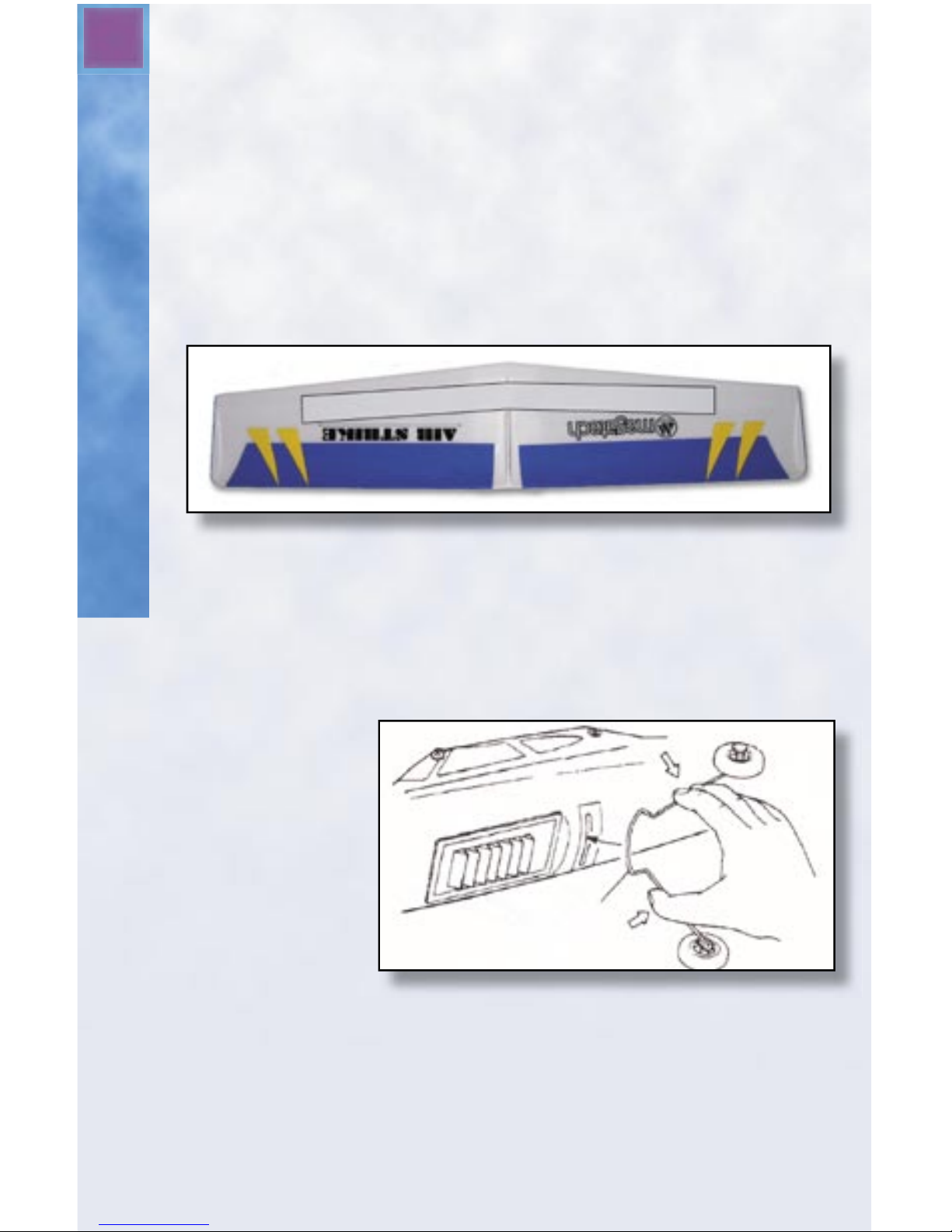
Next, fi nd the strip of white PVC reinforcing tape included with
your kit. This will be applied to the bottom of the wing. Remove
the backing from the PVC tape and stick the tape to the center
section of the wing as shown in Figure 3. Do not conform the tape
to the shape of the ridge in the center of the wing. Leave an air gap
between the tape and the ridge. Make sure that there is an equal
length of tape on each wing panel. Press the tape down fi rmly to
the wing surface. The tape will help to reinforce the wing against
excessive fl ight loads, which will naturally occur during steep
climbs or descents.
Figure 3 - Place PVC tape along bottom of wing as shown.
Step 2: Assemble the Landing Gear
Grasp the legs of the main landing gear. Gently squeeze the legs together,
and then push the gear into the slot on the bottom of the fuselage behind
the battery door. See
Figure 4. Press fi rmly,
but gently until it is in all
the way. Then release the
pressure on the gear legs
and give them a gentle
tug to make sure they are
secure. To remove the
main gear, simply squeeze
the gear legs together to
release the gear from the
housing and pull it out of
the slot.
Figure 4 - Landing Gear Placement
7
Assemble the Tail Surfaces
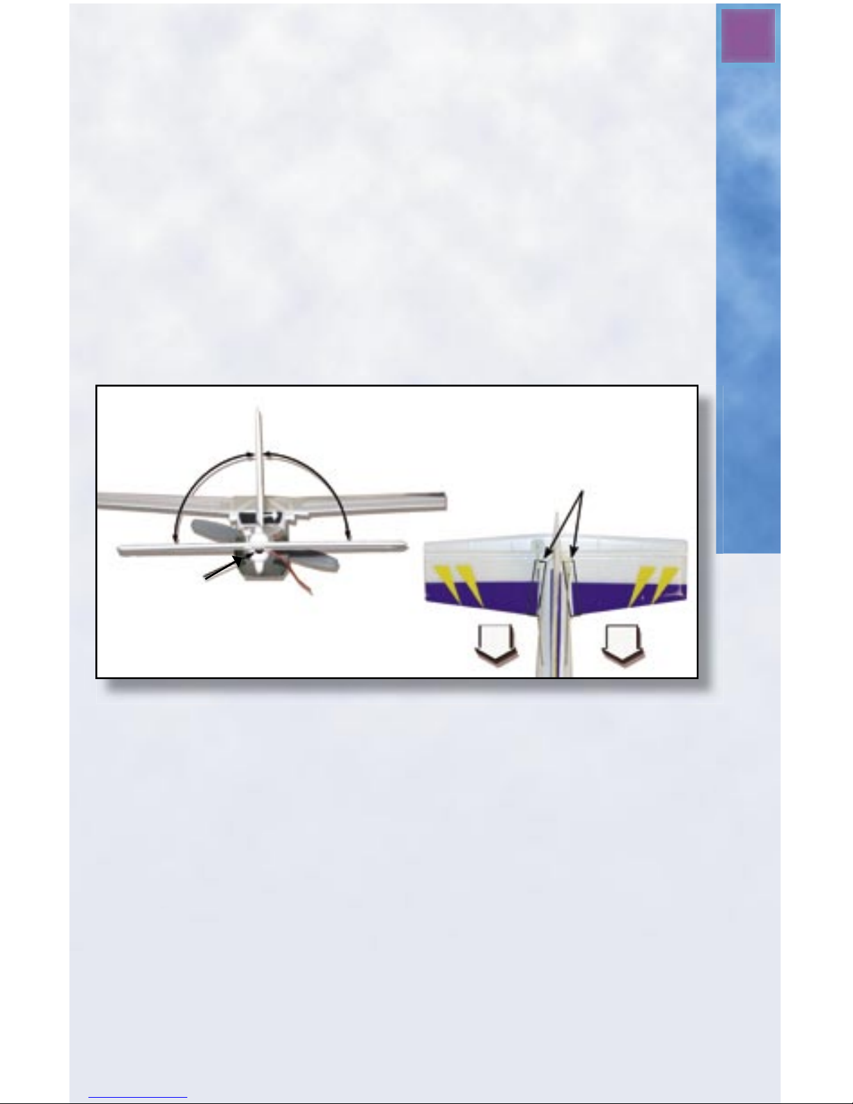
Step 3: Assemble the Tail Surfaces
Locate the horizontal stabilizer from your kit. Carefully slide the
horizontal stabilizer into the slot located at the rear of the
fuselage as shown in Figure 5. The elevator control horn should be
pointing upward. Route the antenna under the horizontal stabilizer,
so it exits from the indentation in the rear of the fuselage. Make
certain that the stabilizer is perfectly level and 90 degrees to the
vertical fi n as indicated in the picture. When the horizontal
stabilizer is properly aligned, apply two pieces of clear tape where
the fuselage meets the stabilizer as shown in Figure 5. Be careful
not to place tape over the moveable portion of the stabilizer
(elevator).
Apply
tape
here.
90°
90°
Antenna should
exit here.
Figure 5 - Push horizontal stabilizer (tail) in from the rear.
Next, snap the plastic control links into place. The hook (clevis) at the
end of the push rod on the left side of the plane attaches to the hook
(horn) on the rudder. The clevis on the right connects to the elevator
control horn. Don’t worry if the rudder and elevator are not straight.
They will be adjusted later.
Step 4: Attach the Wing to the Fuselage
A. Set the wing on the fuselage. Carefully align the center of the
wing onto the saddle area of the fuselage. Look at the picture on
the box if you’re not sure what is the front and what is the back
of the wing.
8
Attaching the Main Wing
The Air Strike Radio System
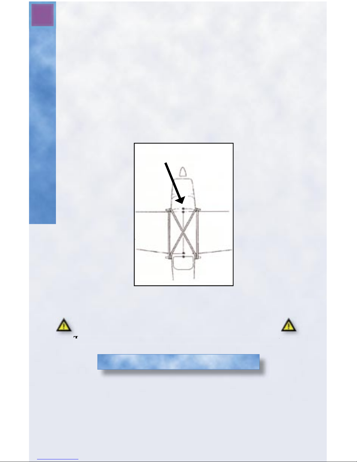
B. Attach 4 wing bands. Install one on each side in a II
pattern. Then Install two bands in a X pattern (Crossed
over each other). See Figure 6.
C. After the wing bands are installed, check the wing once
again to make certain that it is still perfectly centered.
When perfectly centered, make an alignment mark (use a
pencil or felt-tip marker) at the front and rear of the wing
where it meets the fuselage. The marks will make it easier
to align the main wing next time you install it.
Alignment Marks
Figure 6 - Attaching the Main Wing
Important Note!
Disassemble your Air Strike® when not fl ying.
This will help reduce the chance of accidental damage.
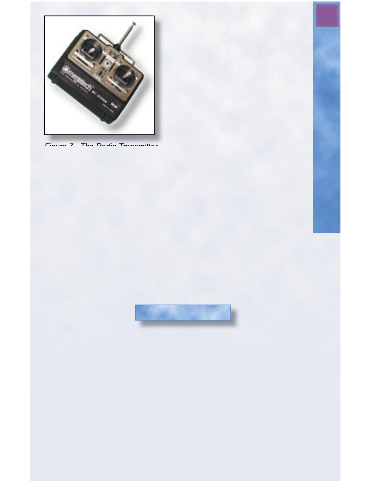
This aircraft uses a 3-channel R/C (radio control) system. See Figure 7.
The stick on the left side of the transmitter operates the motor. When this
stick is all the way in the “down” position, the motor is off. Power
increases as the stick is moved up. Full power is reached when the left
stick is positioned fully “up”. The right stick controls the elevator (up and
down) function and the rudder (right and left) function.
9
The Transmitter and Battery
Figure 7 - The Radio Transmitter
There is a battery LED light
located at the center top of the
transmitter face. Green indicates
adequate battery power. Red
means that the transmitter
batteries are low and must be
replaced. Never attempt to fl y
when the LED light is red! This
will result in loss of control and
most likely a crash!
The radio system is tuned to a
specifi c frequency channel in the
72 MHz band. The crystals in both the transmitter and receiver
may NOT be changed. Attempting to do so is a violation of FCC
(Federal Communications Commission) law and will render your
radio unusable! Contact our service center if you think there may
be a problem with your radio or should you need to change the
frequency.
There is an auto-cutoff feature in the aircraft that allows both the radio
system and the motor to be powered from the same fl ight pack. When the
fl ight pack starts to run low, it will automatically shut off the motor, while
leaving enough reserve power for the radio (about 3-4 minutes) to control
the servos and glide in for a safe landing. Land the plane as soon as
possible when the power runs out.
The battery pack included with the Air Strike® (see Figure 8) is made up
of NiMH (nickel-metal-hydride) rechargeable cells. These are very different from regular dry cell batteries! With proper care and charging methods,
these packs can be charged and used hundreds of times before they need to
be replaced.
Important: The Air Strike uses a special battery with polarized connec-
tors. Do not use any battery pack for this aircraft other than original
Megatech™ equipment. Use of any other battery pack may cause damage to the aircraft and void your warranty!
The Battery Pack
 Loading...