

Page 1

MELCHOR GABILONDO, S.A.
Polígono Industrial Eitua, 6 / 48240 Bérriz (Vizcaya) ESPAÑA / Tel. 94 622 50 90
Intl.: 34-94 622 50 90 / Telefax: 94 622 52 78 / Intl.: 34-94 622 52 78
Teléfono Ventas: 94 622 50 30 / Telefax Ventas: 94 682 73 50
E-MAIL: interior@mega-sa.com / export@mega-sa.com
Web: www.mega.es
Page 2
Page 3

We have come a long way, but after more
than fifty years our course is still market by the
desire to achieve quality and innovation so
that we can live up to our permanent
commitment to improvement.
We maintain our innovative spirit, high standards
of quality and strict checks of material and
processes. We are making our tools more
powerful, safer, more operative and longer
lasting.
Thus we place our experience in your hands.
The high reputation of MEGA
abroad has enabled us to
consolidate a firm position on
the markets of all five
continents.
Plate laser cutting and welding
facilities. CEGAMA
Head office and factory of hydraulic components. BERRIZ Painting installation, general warehouses and despatching area. BERRIZ.
Page 4

Read carefully the safety, user and
maintenance instructions provided with
the equipment. If these basic rules are not
followed injury to the user, the hydraulic
equipment or the load to be lifted may
result.
Position the cylinder on a solid, even
and horizontal surface.
Never use the cylinder on a slope.
Keep a safe distance from the load
during operation.
Never position any part of your body under
the load.
Always secure the load with mechanical
stands.
Clean couplers before connecting and make
sure the connections are securely tightened.
Never exceed the rated capacity of the
cylinder.
It is strongly recommended the use of a
gauge to check the pressure.
Prevent hoses from sharp bending and do
not drop objects on them.
Never disconnect couplers unless the piston
is fully retracted.
Always use a safety cock to block the cylinder.
Avoid extreme heat and temperatures over
65ºC .
Never use cylinders without a saddle.
The saddle helps centre the load.
Never use excessive tightening force that
may damage the fittings. Do not use tools.
Never use extensions on hand pumps or jacks.
Use only the lever provided.
Always use a cylinder of a capacity and hydraulic stroke 25% higher than
the weight of the load to be lifted.
Use original MEGA oil.
IMPORTANT. An excess of oil will render the
pump inoperative.
VERY IMPORTANT.- Never use brake fluid.
After use, retract the piston completely, clean
the equipment and keep it protected from
aggressive environment.
Repair kits are available for every item in this
calalogue.
Always indicate the reference of the item for
which the kit is intended.
Page 5
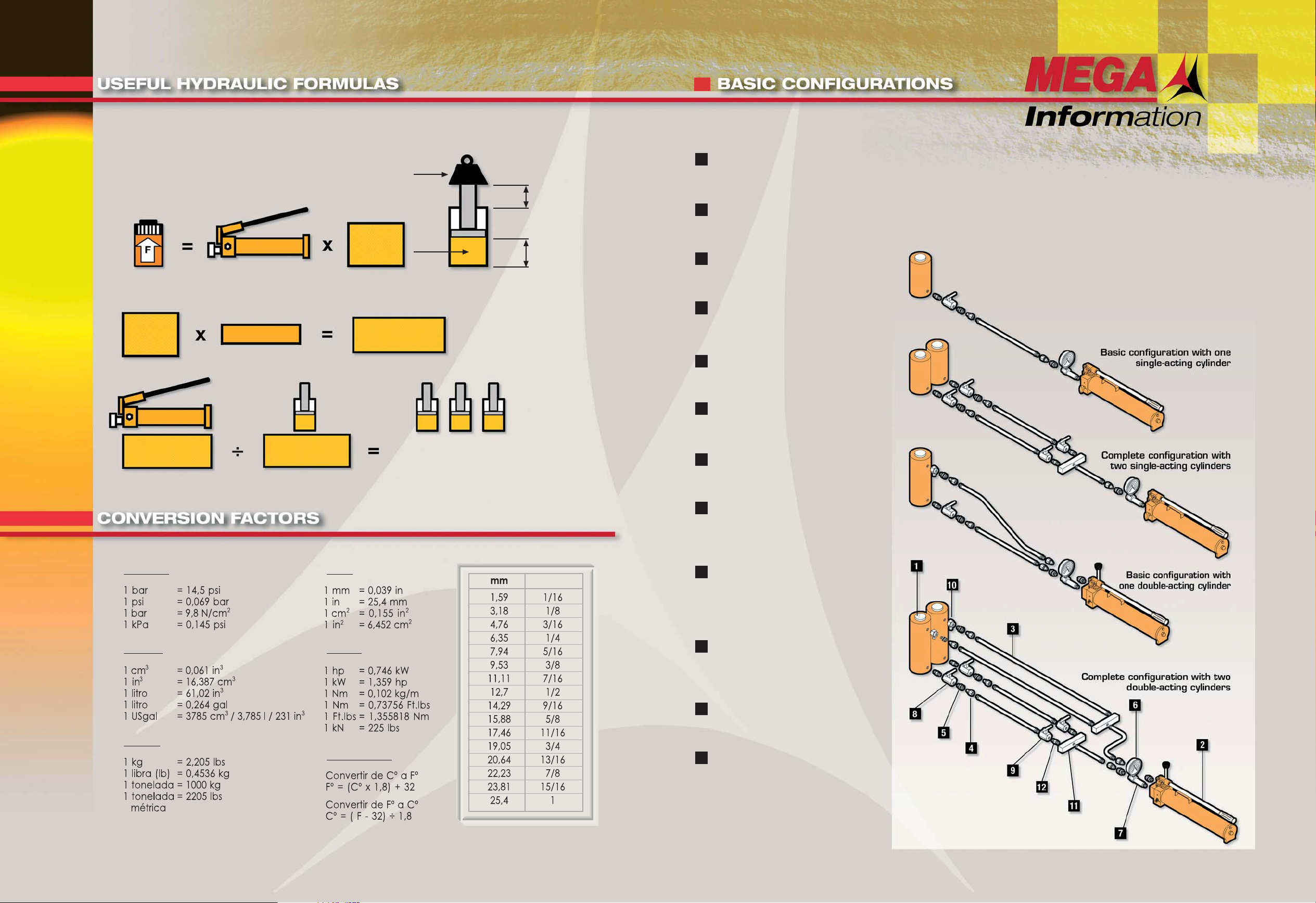
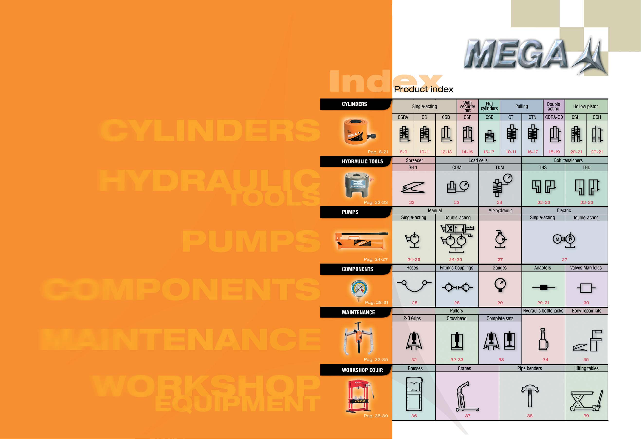
A basic hydraulic configuration consists of a single-acting cylinder, a pump
and a hose. It is really a small machine with the following components:
a) Flow generator = Pump. b) Flexible hose to transmit the oil flow from pump
to cylinder. c) Hydraulic cylinder, consisting of a chamber with inlet for the
oil and a piston to retain the oil and maintain the pressure that raises or
lowers as the oil changes within the chamber. The pressure is
created by resistance to flow. This resistance is the result
of a load. This hydraulic equipment can be used in
virtually all types of industry. From a basic pump
and cylinder set, you can build many
different system configurations by
adding components and
accessories.
1
2
3
4
5
6
7
8
9
10
11
12
Cylinder
To raise the load.
Page 8
Pump
Creates the hydraulic flow.
Page 24
Hose
Transmits the oil flow.
Page 28
A-5507-M
Male quick coupler
Page 28
A-5507-H
Female quick coupler
Page 28
Gauge
To control pressure.
Page 29
Gauge adapter
To mount the gauge.
Page 29
A-5510
Safety valve
Locks the load on raised cylinder.
Page 30
A-5509
Shutoff valve
Shuts the oil flow and locks
the load on raised cylinder.
Page 30
A-5538
Safety relief valve
Avoids accidental overpressure.
Page 30
Manifold
To distribute the oil flow.
Page 31
12 A-5511
Male connector
To connect different components.
Page 31
Capacity (kg)
Pressure (kg/cm
2
- psi)
Effective
area
(cm
2
/ in2)
Stroke
Volume of oil
(cm3/ in3)
Load
Cylinder
effective area
Stroke
Oil volume
of cylinder
Oil volume
of pump
Oil volume
of cylinder
Number of cylinders that can be used with
one pump.
With long hoses, add 35 cm
3
for each meter
used.
Basic hydraulic calculations for the correct selection of cylinders and pumps.
cm3 / in
3
cm / in
cm
2
in
2
Pressure:
Volume:
Weight:
Area:
Others:
Temperature:
Inches
Please note that the dimensions of this catalogue are exact in the metric system ( mm )
and approximate in inches.
Page 6
8 9
Mounting applications
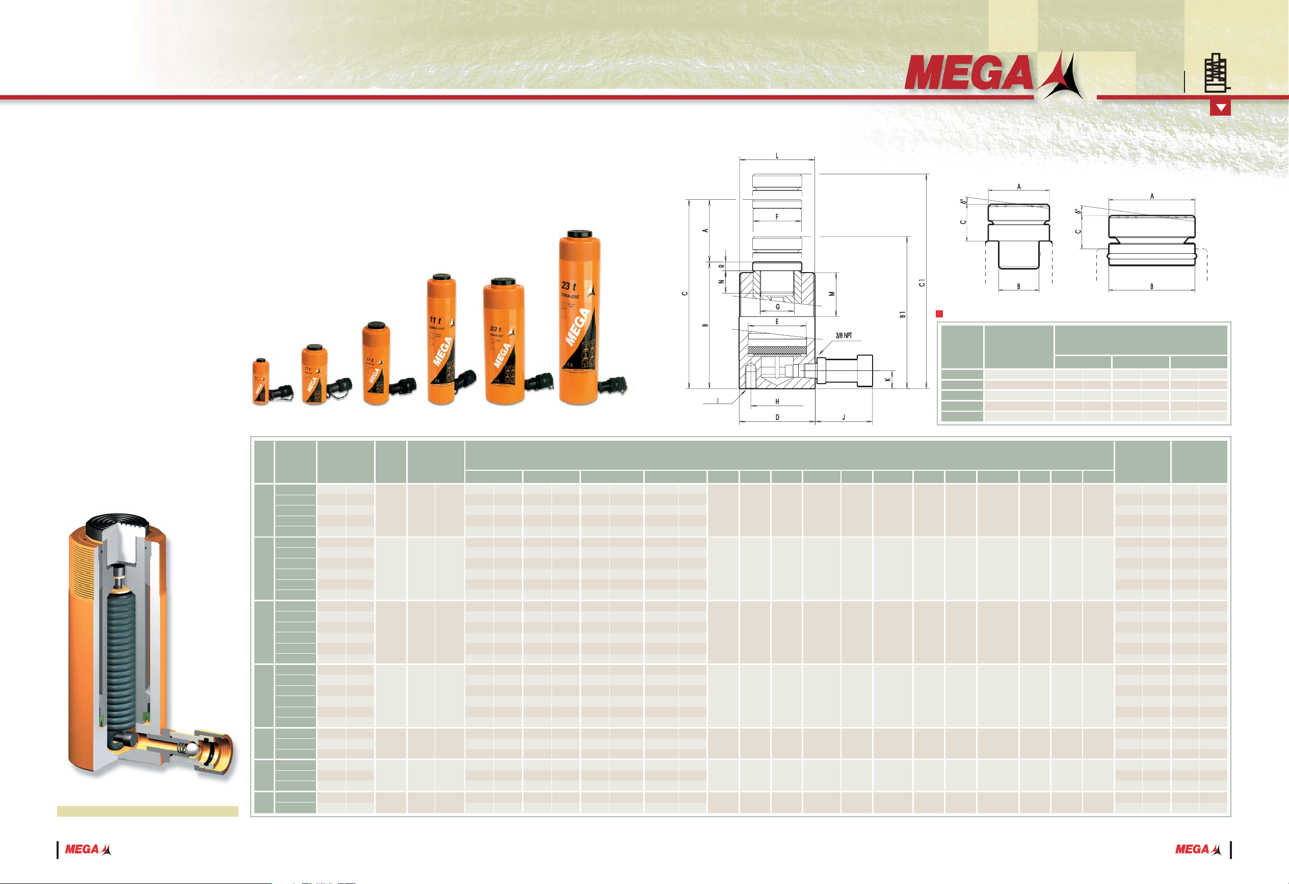
CSRA Series
HYDRAULIC CYLINDERS
Tilting saddle ( optional )
CSRA-5
CSRA-11, CSRA-16
CSRA-23, CSRA-31
CSRA-55
CSRA-93
BCSRA-5
BCSRA-11
BCSRA-23
BCSRA-55
BCSRA-93
Ref. Used with
ABC
Dimensions mm/in.
11
/16
7
/8
1 7/16
2 13/64
2 7/8
15
20
23
25
31
19
/32
25
/32
29
/32
1
1
7
/32
26
40
55
65
80
1 1/32
1 9/16
2 11/64
2 9/16
3 6/32
17,4
22,1
36,3
56
73,5
25
75
125
175
225
25
50
100
150
200
250
25
50
100
150
200
250
25
50
100
150
200
250
50
150
200
50
100
150
50
150
1
2
15
/16
4 15/16
6 7/8
8 7/8
1
2
3
15
/16
5 15/16
7 7/8
9 7/8
1
2
3
15
/16
5 15/16
7 7/8
9 7/8
1
2
3
15
/16
5
1 5
/16
7 7/8
9 7/8
2
5
15
/16
7 7/8
2
3
15
/16
5 15/16
2
3
15
/16
CSRA-5A
CSRA-5B
CSRA-5C
CSRA-5D
CSRA-5E
CSRA-11A
CSRA-11B
CSRA-11C
CSRA-11D
CSRA-11E
CSRA-11F
CSRA-16A
CSRA-16B
CSRA-16C
CSRA-16D
CSRA-16E
CSRA-16F
CSRA-23A
CSRA-23B
CSRA-23C
CSRA-23D
CSRA-23E
CSRA-23F
CSRA-31B
CSRA-31D
CSRA-31E
CSRA-55B
CSRA-55C
CSRA-55D
CSRA-93B
CSRA-93D
5
11
16
23
31
55
93
Rated
capacity
Ref. Stroke
Maximum
capacity
Effective area
tn
A
kN cm
2
in
2
BB1 CC1 DEF G
H
ILMNR
cm
3
in
3
Kg.
Oil volume WeightDimensions mm/in.
JK
B1, C1 with tilting saddle
lbs.
mm. in.
18
54
90
126
162
40
80
160
240
320
400
60
120
240
360
480
600
83
166
332
498
664
830
220
660
880
392
784
1176
664
1992
1,1
3,3
5,5
7,7
9,9
2,45
4,9
9,75
14,65
19,5
24,4
3,65
7,3
14,65
22
29,3
36,6
5,05
10,1
20,2
30,4
40,5
50,6
13,4
40,3
53,7
23,9
47,8
71,8
40,5
121,6
2,2
3,2
4,2
5,6
6,5
5,3
6,4
8,6
10,8
13,2
15,4
7,6
9,15
12,2
15,4
19
22,3
12,8
15
19,7
24,5
28,7
34,2
24,2
36,8
43
36
45,4
55,8
71,2
108,7
70
2
3
/4
70
2
3
/4
70
2
3
/4
70
2
3
/4
70
2
3
/4
70
2
3
/4
70
2 3/4
20
25
/32
20
25
/32
20
25
/32
20
25
/32
37
1 7/16
20
25
/32
47
1 27/32
1 1/2-16UN
2 1/4-14UNS
2 3/4-16UN
3 5/16-12UNS
3
5
/16-12UNS
5-12UN
6
7
/8-12UN
29
1
9
/64
27
1
1
/16
30
1
3
/16
49
1
15
/16
51
2
45
1
25
/32
50
1 31/32
16
5
/8
17
11
/16
17
11
/16
25
1
25
1
6
15
/64
6
15
/64
10
25
/64
10
25
/64
10
25
/64
2
6
/64
2
6
/64
1
/4-20UNC
5
/16-18UNC
3
/8-16UNC
1
/2-13UNC
----
1
/2-13UNC
----
40
1
9
/16
60
2 11/32
70
2
3
/4
85
3 11/32
100
3 15/16
130
5 1/64
175
6
7
/8
30
1
3
/16
45
1 49/64
55
2 11/64
65
2 9/16
75
2 61/64
100
3 15/16
130
5
1
/8
26
1
1
/32
39
1 17/32
46
1 13/16
54
2 1/8
57,15
2 1/4
80
3 6/32
105
4
9
/64
3
/4-16UNF
1-8UNC
1-8UNC
1 1/2-16UN
1 1/2-16UN
----
----
25
63
/64
40
1
9
/16
48
1
7
/8
59
2
5
/16
----
95
3 3/4
----
125
175
227
288
339
139
164
214
264
318
368
144
169
220
272
329
382
163
188
239
290
347
398
219
319
369
194
244
294
221
321
4
15
/16
6 7/8
8 15/16
11 5/16
13 11/32
5 1/2
6 7/16
9 7/16
10 3/8
12 1/2
14 1/2
5 11/16
65/8
8 11/16
10 11/16
13
16
6
7
/16
7 3/8
9 7/16
11 7/16
13 11/16
15 11/16
8 5/8
12 9/16
14 1/2
7 5/8
9 5/8
11 9/16
8 11/16
12 5/8
150
250
352
463
564
164
214
314
414
518
618
169
219
320
422
529
632
188
238
339
440
547
648
269
469
569
244
344
444
271
471
5
7
/8
9 7/8
13 7/8
18 1/4
22 3/16
6 7/16
8 7/16
12 3/8
16 5/16
20 3/8
24 5/16
6 11/16
8 5/8
12 5/8
16 5/8
20 7/8
24 7/8
7 3/8
9 3/8
13 5/16
17 5/16
21 1/2
25 1/2
10 5/8
18 7/16
22 3/8
9 5/8
13 9/16
17 1/2
10 11/16
18 9/16
135
235
337
448
549
144
194
294
394
498
598
149
199
300
402
509
612
165
215
316
417
524
625
244
444
544
219
319
419
240
440
5
5
/16
9 1/4
13 1/4
17 5/8
21 5/8
5 11/16
7 5/8
11 9/16
15 1/2
19 5/8
23 1/2
5 7/8
7 7/8
11 13/16
15 7/8
20
24
1
/64
6 1/2
8 1/2
12 7/16
16 3/8
20 5/8
14 5/8
9 5/8
17 1/2
21 3/8
8 5/8
12 9/16
16 1/2
9 7/16
17 5/16
110
160
212
273
324
119
144
194
244
298
348
124
149
200
252
309
362
140
165
216
267
324
375
194
294
344
169
219
269
190
290
4
11
/32
6 15/16
8 3/8
10 3/4
12 3/4
4 11/16
5 11/16
7 5/8
9 5/8
11 3/4
13 3/4
4 7/8
5 7/8
7 7/8
9 15/16
12 6/32
14 1/4
5 1/2
6 1/2
8 1/2
10 1/2
12 3/4
14 3/4
7 5/8
11 9/16
13 9/16
6 5/8
8 5/8
10 5/8
7 1/2
11 7/16
48,5
109,1
163
227,7
303,1
539
910,9
1
1,45
1,92
2,48
2,94
2,4
2,9
3,9
4,9
6
7
3,45
4,15
5,55
7
8,6
10,1
5,8
6,8
8,95
11,1
13
15,5
11
16,7
19,5
15,9
20,6
25,3
32,3
49,3
7,06
15,9
23,75
33,08
44,18
78,54
132,73
1,09
2,46
3,68
5,12
6,84
12,17
20,57
----
----
Working pressure: 700 kg/cm2/10.000 psi.
All pistons have a salt bath nitriding treatment
or a hard chrome plating, depending on the
model, to resist corrosion and for longer life.
With built-in bronze guide for easier sliding
of piston.
These cylinders are fitted with a removable
grooved saddle, pressure mounted or screwed
in the piston head. They are also equipped
with a high flow female quick coupler with
dust cap, ref. A-5507-H.
Carry handles on models weighing from
20 kg/44 lbs to 40 kg/88 lbs. Heavier models
are fitted with eye hooks for transport.
With mounting holes and threaded areas
protected against blows for easy coupling or
special tooling applications.
Cross section view
Single-acting, spring return
Page 7
10 11
Coupling applications
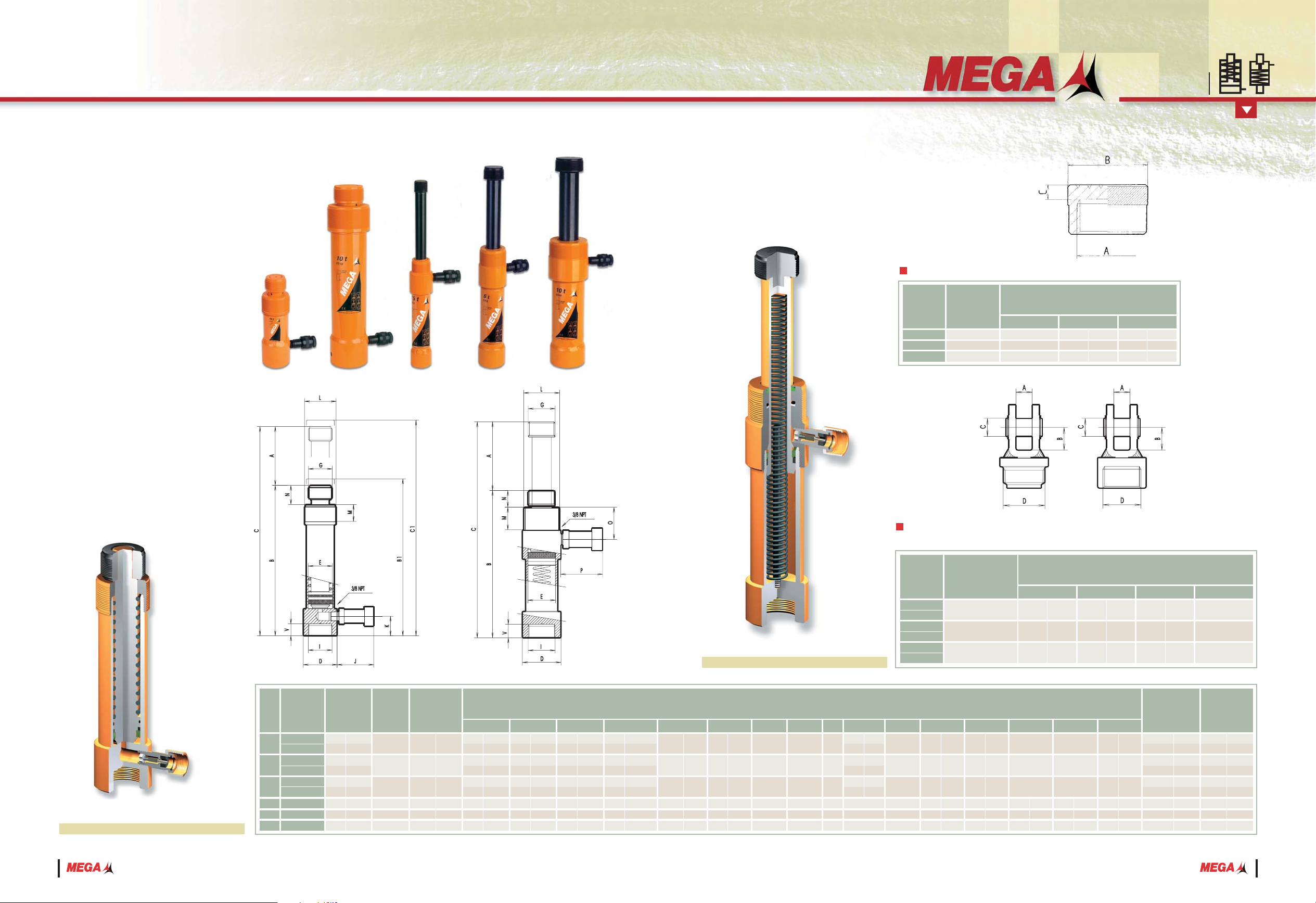
CC
CT Series
HYDRAULIC CYLINDERS
CC: PUSHING
CT: PULLING
Working pressure: 700 kg/cm2/10.000 psi.
All pistons have an induction hardening
treatment or a salt bath nitriding process
depending on the model.
Each ram is equipped with a female quick
coupler with air dust cap, ref. A-5507-H.
With mounting holes and protected
threaded areas against possible blows for
easy coupling or special tooling applications.
Unlike the pushing cylinders, the pulling
rams retract toward the base to apply
pressure.
These pushing and pulling cylinders can
be original components of the Maintenance
Kits described on page 35.
Cross section view ( CC )
CC-5 SERIES
CC-10 SERIES
CC-20 SERIES
A-5142
A-5042
A-5242
Ref. Used with
ABC
Dimensions mm/in.
1 17/64
2 7/8
2 29/32
8
10
12
5
/16
25
/64
15
/32
M26 x 2
M42 x 2,5
M60 x 2,5
32
54
74
Grooved saddle ( optional )
CC-5A
CC-5B
CC-10A
CC-10B
CC-20A
CC-20B
CT-2,5
CT-5
CT-10
5
10
20
2,5
5
10
Rated
capacity
Ref.
Maximum
capacity
Effective area
tn kN cm2in
2
BB1 CC1 DEGIJKNOPV
cm
3
in3Kg.
Oil volume WeightDimensions mm/in.
LM
lbs.
40
92
73
196
141
368
54
103
199
2,44
5,61
4,45
11,96
8,6
22,46
3,29
6,28
12,14
3
4,9
5,3
9,6
12,1
2,2
5
8,6
17,6
M26 x 2
M42 x 2,5
M60 x 2,5
M26 x 2
M42 x 2,5
M60 x 2,5
70
2
3
/4
70
2
3
/4
70
2
3
/4
----
----
----
1,35
2,2
2,4
4,35
5,5
10
2,25
3,9
8
50
115
50
135
50
130
127
138
138
2
4
1
/2
2
5
5
/16
2
5
1
/8
5
5
7
/16
5 7/16
55
99,6
194
29,1
51,1
99
8,04
14,52
28,27
4,24
7,45
14,41
1,24
2,25
4,38
0,65
1,15
2,23
177
284
191
332
216
364
270
311
318
6
15
/16
11 3/16
7 1/2
13 1/16
8 1/2
14 5/16
10 5/8
12 1/4
12 1/2
184
292
201
342
228
376
----
----
----
7
5
/16
11 1/2
7 15/16
13 7/16
9
14
13
/16
----
----
----
227
399
241
467
266
494
397
449
456
8
15
/16
15 11/16
9 1/2
18 3/8
10 1/2
19 7/16
15 5/8
17 11/16
17 15/16
235
407
251
477
278
506
---
---
---
9
1
/4
16
9
7
/8
18 3/4
10 15/16
19 15/16
---
---
---
Stroke
A
mm. in.
M26 x 2
M42 x 2,5
M60 x 2,5
M26 x 2
M42 x 2,5
M60 x 2,5
45
60
79
45
60
79
M38 x 1,5
M56 x 2
M84 x 2
M38 x 1,5
M56 x 2
M84 x 2
----
----
----
70
70
70
2
3
/4
2 3/4
2 3/4
----
----
----
70
70
70
2
3
/4
2 3/4
2 3/4
----
----
----
33
30
38
35
44
40
1 5/
16
1 3/
16
1 1/
2
1 3/
8
1 3/
4
1 9/
16
B1, C1 with tilting saddle
1 49/64
2 11/32
3 1/8
1 49/64
2 11/32
3 1/8
32
43
60
32
43
60
1 1/4
1 11/16
2 11/32
1 1/4
1 11/16
2 3/8
22
36
48
24
35
35
7
/8
1 7/16
1 7/8
15
/16
1 3/8
1 3/8
20
26
30
21
24
27
13
/16
1 1/32
1 3/16
1 13/16
15
/16
1 1/16
18
21
23
16
21
21
11
/16
13
/16
7
/8
5
/8
13
/16
13
/16
Cross section view ( CT )
CC-5, CT-2,5 SERIES
CC-10, CT-5 SERIES
CC-20, CT-10 SERIES
A-5188
A-5189
A-5088
A-5089
A-5288
A-5289
Ref. Used with
ABC
Dimensions mm/in.
1
1
1
3
/16
20
20
20
25
/32
25
/32
25
/32
18
18
18
23
/32
23
/32
23
/32
25
25
30
D
M26 x 2
M42 x 2,5
M60 x 2,5
Attachments for pulling and
pushing pistons ( optional )
Single-acting, spring return
Page 8

12 13
General application
CSB Series
HYDRAULIC CYLINDERS
Ideal for a wide range of applications in
civil engineering, heavy fabrication,
construction, maintenance and lifting of
very heavy loads.
38
50
50
50
50
50
150
150
250
150
250
150
250
1
1
/2
2
2
2
2
2
5
15
/16
5 15/16
9 7/8
5 15/16
9 7/8
5 15/16
9 7/8
CSB-11A
CSB-23B
CSB-31B
CSB-55B
CSB-93B
CSB-200B
CSB-200D
CSB-300D
CSB-300F
CSB-400D
CSB-400F
CSB-500D
CSB-500F
11
23
31
55
93
200
300
400
500
Rated
capacity
Ref. Stroke
Maximum
capacity
Effective area
tn
A
kN cm
2
in
2
BB1 CC1 DEF R
cm
3
in
3
Kg.
Oil volume WeightDimensions mm/in.
JK
B1, C1 with tilting saddle
lbs.
mm. in.
60
166
220
392
664
1417
4252
6506
10843
8780
14633
10960
18265
3,66
10,1
13,4
23,9
40,5
86,5
259,6
397,2
662
536
894
669
1115
4,8
11
15,2
28,4
44
156
210
403
515
570
710
755
935
123
140
147
163
160
269
369
436
546
459
569
488
598
4
7
/8
5 1/2
5 13/16
6 7/16
6 5/16
10 5/8
14 1/2
17 3/16
21 1/2
18 1/16
22 3/8
19 3/16
23 9/16
161
190
197
213
210
319
519
586
796
609
819
638
848
6
5
/16
7 1/2
7 3/4
8 3/8
8 1/4
12 9/16
20 7/16
23 1/16
31 5/16
24
32
1
/4
25 1/8
33 3/8
147
174
175
188
180
269
469
521
731
531
741
550
760
5
13
/16
6 7/8
6 7/8
7 7/16
7 1/16
10 5/8
18 7/16
20 1/2
28 13/16
20 7/8
29 3/16
21 5/8
29 15/16
109
124
125
138
130
219
319
371
481
381
491
400
510
4
5
/16
4 7/8
4 15/16
5 7/16
5 1/8
8 5/8
12 9/16
14 9/16
18 15/16
15
19
5
/16
15 3/4
20 1/16
109,1
227,7
303,1
539
910,9
1945,8
2976,5
4017,1
5014
2,2
5
6,9
12,9
20
70,8
95,3
183
234
259
322
343
424
15,9
33,18
44,18
78,54
132,73
283,52
433,73
585,35
730,6
2,46
5,14
6,84
12,17
20,57
43,95
67,24
90,75
113,27
2 11/32
3 3/8
3 15/16
5 1/8
6 7/16
9 9/16
11 7/8
13 3/4
15 7/16
60
85
100
130
163
242
302
349
392
1 49/64
2 9/16
2 61/64
3 15/16
5 1/8
7 1/2
9 1/4
10 5/8
12
45
65
75
100
130
190
235
270
305
1
17
/32
2 1/8
2 1/4
3 6/32
4 9/64
5 15/16
6 11/16
8 1/4
9 7/16
39
54
57,15
80
105
150
170
210
240
2 3/4
2 3/4
2 3/4
2 3/4
2 3/4
2 3/4
2 3/4
2 3/4
2 3/4
70
70
70
70
70
70
70
70
70
15
/16
15
/16
15
/16
15
/16
15
/16
2 7/16
3 1/16
3 7/16
3 9/16
23
23
23
23
23
62
78
88
91
5
/64
5
/64
5
/64
5
/64
5
/64
3
/16
3
/16
3
/16
3
/16
2
2
2
2
2
5
5
5
5
Working pressure: 700 kg/cm2/10.000 psi.
All pistons have a salt bath nitriding
treatment or a hard chrome plating,
depending on the model, to resist corrosion
and for longer life.
With built-in bronze guide for easier sliding
of piston.
These cylinders are fitted with a removable
grooved saddle, pressure mounted or
screwed in the piston head. They are also
equipped with a female quick coupler
with dust cap, ref. A-5507-H.
Carry handles on models weighing from
20 kg/44 lbs to 40 kg/88 lbs Heavier
models are fitted with eye hooks for
transport.
Cross section view
Tilting saddle ( optional )
CSB-11
CSB-23
CSB-31
CSB-55
CSB-93
CSB-200
CSB-300
CSB-400
CSB-500
BCSB-11
BCSB-23
BCSB-31
BCSRA-55
BCSRA-93
BCSB-200
BCSB-300
BCSB-400
BCSB-500
Ref. Used with
ABC
Dimensions mm/in.
1 1/16
1 17/32
1 17/32
2 13/64
2 7/8
4 7/8
5 1/8
6 5/16
7 3/32
14
16
22
25
31
50
65
78
88
35
/64
5
/8
55
/64
1
1
7
/32
2
2
9
/16
3 5/64
3 15/32
40
55
55
65
80
138
155
185
205
1
9
/16
2 11/64
2 11/64
2 9/16
3 6/32
5 7/16
6 1/64
7 9/32
8 1/16
27
39
39
56
73,5
124
130
160
180
Single-acting, load return
Page 9

14 15
With security lock nut
CSF Series
HYDRAULIC CYLINDERS
Working pressure: 700 kg/cm2/10.000 psi.
All pistons have a salt bath nitriding
treatment to resist corrosion.
With built-in bronze guide for easier sliding
of piston.
These cylinders are fitted with a removable
grooved saddle, pressure mounted or
screwed in the piston head. They are also
equipped with a high flow female quick
coupler with dust cap, ref. A-5507-H.
Carry handles on models weighing from 20
kg/44 lbs to 40 kg/88 lbs Heavier models
are fitted with eye hooks for transport.
The mechanical lock of load is effected by
a safety lock nut at the piston extension
desired.
Particularly recommended for foundations
support in construction, bridge building
and maintenance of heavy machinery in
public works or steel industry, specially
when load must be kept on hold for long
periods.
The safety lock nut allows disconnection
of the pump and ensure total safety
conditions when operating under the load.
Cross section view
With tilting saddle ( optional )
CSF-31 SERIES
CSF-55 SERIES
CSF-93 SERIES
CSF-200 SERIES
CSF-300 SERIES
CSF-400 SERIES
CSF-500 SERIES
BCSB-31
BCSRA-55
BCSRA-93
BCSB-200
BCSB-300
BCSB-400
BCSB-500
Ref. Used with
ABC
Dimensions mm/in.
1 17/32
2 13/64
2 7/8
4 7/8
5 1/8
6 5/16
7 3/32
22
25
31
50
65
78
88
55
/64
1
1
7
/32
2
2
9
/16
3 5/64
3 15/32
55
65
80
138
155
185
205
2 11/64
2 9/16
3 6/32
5 7/16
6 1/64
7 9/32
8 1/16
39
56
73,5
124
130
160
180
150
150
150
150
150
250
150
250
150
250
5
15
/16
5 15/16
5 15/16
5 15/16
5 15/16
9 7/8
5 15/16
9 7/8
5 15/16
9 7/8
CSF-31D
CSF-55D
CSF-93D
CSF-200D
CSF-300D
CSF-300F
CSF-400D
CSF-400F
CSF-500D
CSF-500F
31
55
93
200
300
400
500
Nominal
capacity
Ref. Stroke
Maximum
capacity
Effective area
tn
A
kN cm
2
in
2
BB1 CC1 DEF R
cm
3
in
3
Kg.
Oil volume WeightDimensions mm/in.
JK
B1, C1 with tilting saddle
lbs.
mm. in.
660
1176
1992
4252
6506
10843
8780
14633
10960
18265
40,3
71,8
121,6
259,6
397,2
662
536
894
669
1115
294
318
356
424
500
610
528
638
563
673
11
9
/16
12 1/2
14
16
11
/16
19 11/16
24
20
3
/4
25 1/8
22 3/16
26 1/2
444
468
506
574
650
860
678
888
713
923
17
1
/2
18 7/16
19 15/16
22 5/8
25 5/8
33 7/8
26 11/16
35
28
1
/16
36 5/16
422
443
476
524
585
795
600
810
625
835
16
5
/8
17 7/16
18 3/4
20 5/8
23
31
5
/16
23 5/8
31 7/8
24 5/8
32 7/8
272
293
326
374
435
545
450
560
475
585
10
11
/16
11 1/2
12 13/16
14 3/4
17 1/8
21 7/16
17 11/16
22
18
11
/16
23
303,1
539
910,9
1945,8
2976,5
4017,1
5014
14,5
27,2
56,4
125
222
269
315
383
427
515
44,18
78,54
132,73
283,52
433,73
585,35
730,6
6,84
12,17
20,57
43,95
67,24
90,75
113,27
3
15
/16
5 1/8
6 7/8
9 9/16
11 7/8
13 3/4
15 7/16
100
130
175
242
302
349
392
2
61
/64
3 15/16
5 1/8
7 1/2
9 1/4
10 5/8
12
75
100
130
190
235
270
305
TR 2
1
/4 x 5
TR 80 x 5
TR 105 x 5
TR 160
x 5
TR 180 x 5
TR 220 x 5
TR 260 x 5
2
3
/4
2 3/4
2 3/4
2 3/4
2 3/4
2 3/4
2 3/4
70
70
70
70
70
70
70
15
/16
15
/16
1 27/32
2 7/16
3 1/16
3 7/16
3 9/16
23
23
47
62
78
88
91
5
/64
5
/64
5
/64
3
/16
3
/16
3
/16
3
/16
2
2
2
5
5
5
5
32
60
125
275
490
593
695
845
940
1135
Single-acting, load return
Page 10

16 17
Flat cylinders
CSE Series
HYDRAULIC CYLINDERS
Working pressure: 700 kg/cm2/10.000 psi.
All pistons have a salt bath nitriding treatment
to resist corrosion.
Grooved piston ends make optional grooved
saddle unnecessary.
All are equipped with high flow female quick
couplers with dust cap, ref A-5507-H, except
model CSE-5 fitted with a female quick coupler,
ref. A-5506-H.
With mounting holes in the base.
These CSE cylinders have been designed
to combine minimum collapsed height with
optimum stroke.
They are suitable for lifting, clamping,
levelling or positioning jobs where space is
tight.
The spring return piston allows easy removal
from working place.
Working pressure: 700 kg/cm2/10.000 psi.
All pistons have a hard chrome plating
treatment to resist corrosion.
Equipped with high flow female quick coupler
with dust cap, ref. A-5507-H and carrying handle.
Designed for pulling and tensioning
applications, they can be used in those
operations where two heavy pieces have to be
put one near the other.
They are normally used in industrial assembling,
testing, welding operations of plates or heavy
steel frame works.
They are fitted with clevis eyes on both ends
which are linked to attachments welded onto
the plates to join or weld.
AB
C
X
D W
P
O
3/8 PNT
E
F
127
150
150
5
5
15
/16
5 15/16
CTN-10
CTN-30
CTN-50
10
30
50
Nominal
capacity
Ref. Stroke
Maximum
capacity
Effective area
tn
A
kN cm
2
in
2
BC DEF0PW
X
cm
3
in
3
Kg.
Oil volume WeightDimensions mm/in.
lbs.
mm. in.
183
725
1085
11,15
44,3
66,2
21,1
48,6
81,4
625
775
920
24
9
/16
30 1/2
36 7/32
60
100
125
2
11
/32
3 15/16
4 15/16
85
125
155
3
11
/32
4 15/16
6 1/8
18 11/16
24 9/16
30 5/16
9,6
22,1
37
98,95
331,8
497,2
14,42
48,34
72,45
2,23
7,49
11,23
475
625
770
42
62
80
1
21
/32
2 7/16
3 6/32
35
40
44
1
3
/8
1 9/16
1 3/4
70
70
70
2
3
/4
2 3/4
2 3/4
40
50
60
1
9
/16
2
2
11
/32
75
100
150
2
15
/16
3 15/16
5 15/16
CSE-5
CSE-11
CSE-23
CSE-31
CSE-55
CSE-93
5
11
23
31
55
93
Nominal
capacity
Ref.
Maximum
capacity
Effective area
tn kN cm
2
in
2
BCD TU
cm
3in3
Kg.
Oil volume WeightDimensioes mm/in.
lbs.
5
18
37
53
125
212
0,77
2,8
5,73
8,2
19,4
32,8
1,65
3,85
7,05
10,5
20,7
37,9
0,75
1,75
3,2
4,8
9,4
17,2
1
/4
7
/16
7
/16
15
/32
5
/8
5
/8
7,06
15,9
33,08
44,18
78,54
132,73
1,09
2,46
5,12
6,84
12,17
20,57
1 3/8
1 3/4
2 1/8
2 11/32
2 27/32
3 15/32
1 19/32
2 3/16
2 9/16
2 27/32
3 15/32
4 3/32
60
79
98
115
147
180
2
11
/32
3 1/8
3 7/8
4 17/32
5 25/32
7 3/32
Stroke
A
mm. in.
13
/16
1 1/64
1 9/16
1 13/16
2 7/16
3 1/8
7
/8
1 5/16
1 7/16
1 3/4
2 5/16
2 15/16
48,5
109,1
227,7
303,1
539
910,9
20
28
40
47
62
80
22
34
37
44
58
75
6,5
11
11
12
16
16
34
44,5
54
60
72
88
40,5
55,5
65
72
88
104
EFHIJ
K
RS
30
45
65
75
100
130
1
3
/16
1 49/64
2 9/16
2 61/64
3 15/16
5 1/64
1 1/32
1 17/32
2 1/8
2 1/4
3 6/32
4 9/64
1 3/32
1 29/64
2
2
3
/64
2 3/4
3
7
/32
1
/4
23
/64
23
/64
7
/16
9
/16
2 11/32
2 3/4
2 3/4
2 3/4
2 3/4
2 3/4
11
/16
15
/16
15
/16
15
/16
15
/16
15
/16
3
/64
3
/64
3
/64
3
/64
3
/64
3
/64
1 5/8
2 13/64
3 1/8
3 11/16
4 7/8
6 5/16
26
39
54
57,15
80
105
28
37
50
52
70
76
5,5
6,6
9
9
11
14
60
70
70
70
70
70
17
23
23
23
23
23
41
56
80
94
124
160
1
1
1
1
1
1
Cross section view
CTN Series
Pulling cylinders
HYDRAULIC CYLINDERS
Single-acting, spring-return
Single-acting, spring return
Page 11

18 19
Double-acting cylinders
CDRA
CD Series
HYDRAULIC CYLINDERS
Working pressure: 700 kg/cm2/10.000 psi.
All pistons have a salt bath nitriding treatment
or a hard chrome plating, depending on the
model, to resist corrosion and for longer life.
With built-in bronze guide for easier sliding
of piston.
Fitted with a relief safety valve, ref. A-5538
on the piston retract side, to prevent accidental
overpressure.
These cylinders are fitted with a removable
grooved saddle, pressure mounted or screwed
in the piston head. Are also equipped with
a high flow female quick coupler with dust
cap, ref. A-5507-H.
Carry handles on models weighing from
20 kg/44 lbs to 40 kg/88 lbs. Heavier models
are fitted with eye hooks for transport.
With mounting holes and threaded areas
protected against blows for easy coupling or
special tooling applications.
The hydraulic force being applied in both
directions, these cylinders are very solid and
used where a precision operation is required
to move or position loads accurately on the
assembly place. Widely demanded in public
works and big structure manufacture.
*E= Pushing
*T= Pulling
Cross section view
CDRA-9
CDRA-23, CDRA-31
CDRA-55
CDRA-93
CD-200
CD-300
CD-400
CD-500
BCSRA-11
BCSRA-23
BCDRA-55
BCDRA-93
BCSB-200
BCSB-300
BCSB-400
BCSB-500
Ref. Used with
ABC
Dimensions mm/in.
7
/8
1 7/16
57
/64
21
/32
4 7/8
5 1/8
6 5/16
7 3/32
20
23
40
46
50
65
78
88
25
/32
29
/32
1 9/16
1 13/16
2
2
9
/16
3 5/64
3 15/32
40
55
65
80
138
155
185
205
1
9
/16
2 11/64
2 9/16
3 6/32
5 7/16
6 1/64
7 9/32
8 1/16
22,1
36,3
22,7
42,2
124
130
160
180
Tilting saddle ( optional )
Hydraulic return
CDRA-9D
CDRA-23D
CDRA-31D
CDRA-55D
CDRA-55F
CDRA-93D
CDRA-93F
CD-200D
CD-200F
CD-300D
CD-300F
CD-400D
CD-400F
CD-500D
CD-500F
9
23
31
55
93
200
300
400
500
Nominal
capacity
Ref.
Maximum
capacity
Effective area
tn kN cm
2
in
2
BB1 CC1 DEFG
J
KNOPR
cm
3
in
3
Oil volume WeightDimensions mm/in.
LM
lbs.
5,8
10,4
19,8
28,2
37
60,3
77,3
135
173
210
261
301
373
388
476
150
150
150
150
250
150
250
150
250
150
250
150
250
150
250
5 15/16
5 15/16
5 15/16
5 5/16
9 7/8
5 5/16
9 7/8
5 5/16
9 7/8
5 5/16
9 7/8
5 5/16
9 7/8
5 5/16
9 7/8
285
315
338
321
421
355
455
356
456
412
512
417
517
439
539
11 3/16
12 7/16
13 5/16
12 5/8
16 9/16
14
17
7
/8
14
17
7
/8
16 7/32
20 6/32
16 13/32
20 11/32
17 9/32
21 7/32
305
338
363
361
461
401
501
406
506
477
577
495
595
527
627
435
465
488
471
671
505
705
506
706
562
762
567
767
589
789
17 1/8
18 5/16
19 7/32
18 17/32
26 13/32
19 7/8
27 3/4
19 15/16
27 3/4
19 15/16
30
22
5
/16
30 3/16
23 3/16
31 1/16
455
488
513
511
711
551
751
556
756
627
827
645
845
677
877
Stroke
A
mm. in.
60
85
100
130
175
242
302
349
392
B1, C1 with tilting saddle
12,56
4,62
33,18
10,28
44,18
18,55
78,54
28,28
132,73
46,14
283,52
433,73
585,35
730,6
E
T
E
T
E
T
E
T
E
T
E
E
E
E
86,24
31,72
227,7
70,54
303,1
127,3
539
194,07
910,9
316,6
1945,8
----
2976,5
----
4017,1
----
5014
----
E
T
E
T
E
T
E
T
E
T
E
T
E
T
E
T
E
T
1,94
0,71
5,12
1,6
6,84
2,87
12,17
4,38
20,57
7,15
43,95
67,24
90,75
113,27
E
T
E
T
E
T
E
T
E
T
E
E
E
E
12
13
5
/16
14 9/32
14 7/32
18 9/64
15 3/4
19 3/4
16
10
1
/8
18 3/4
22 11/16
19 1/2
23 7/16
20 3/4
24 11/16
17 15/16
19 7/32
20 3/16
20 1/64
28
21
11
/16
29 9/16
21 7/8
29 3/4
24 11/16
32 9/16
25 3/8
33 1/4
26 5/8
34 1/2
2 11/32
3 3/8
3 15/16
5 1/8
6 7/8
9 9/16
11 7/8
13 3/4
15 7/16
40
65
75
100
130
190
235
270
305
1
37
/64
2 9/16
2 61/64
3 15/16
5 1/8
7 1/2
9 1/4
10 5/8
12
1
1
/4
2 1/8
2 1/4
3 6/32
4 9/64
5 15/16
6 11/16
8 1/4
9 7/16
1 - 8 UNC
1
1
/2 - 16 UN
1
1
/2 - 16 UN
1 - 12 UNF
1
3
/4 - 12 UN
----
----
----
----
70
70
70
70
70
70
70
70
70
2
3
/4
2 3/4
2 3/4
2 3/4
2 3/4
2 3/4
2 3/4
2 3/4
2 3/4
23
23
37
23
47
62
78
84
90
15
/16
15
/16
1 7/16
15
/16
1 27/32
2 7/16
3 1/16
3 5/16
3 17/32
2 1/4 - 14 UNS
3
5
/16 - 12 UNS
3
5
/16 - 12 UNS
5 - 12 UN
6
7
/8 - 12 UN
----
----
----
----
----
----
----
----
27
49
49
45
50
1
1
/16
1 15/16
1 15/16
1 3/4
2
----
----
----
----
17
25
25
38
50
11
/16
1
1
1
1
/2
2
47
70
75
65
70
65
82
90
92
1
7
/8
2 3/4
2 7/8
2 9/16
2 3/4
2 9/16
3 1/4
3 9/16
3 5/8
113
113
113
113
113
113
113
113
113
4
7
/16
4 7/16
4 7/16
4 7/16
4 7/16
4 7/16
4 7/16
4 7/16
4 7/16
6
10
10
15
15
5
5
5
5
E
T
E
T
E
T
E
T
E
T
E
T
E
T
E
E
E
E
E
E
E
E
11,6
3,23
30,5
9,46
40,6
17,1
71,8
26
120
43,1
121,6
42,2
202,5
70,5
260
432,7
397
662
525
87,4
670
115
Kg.
15
/64
25
/64
25
/64
19
/32
19
/32
3
/16
3
/16
3
/16
3
/16
E
T
E
T
E
T
E
T
E
T
E
T
E
T
E
E
E
E
E
E
E
E
12,7
22,9
43,5
62
81,4
132,6
170
297
380
462
574
662
820
853
1047
31,8
54
57,15
80
105
150
170
210
240
190
53
500
155
665
280
1175
425
1965
707
1992
692
3318
1154
4253
7088
6506
10845
8590
14315
10960
18265
Page 12

20 21
CSH: Single-acting, spring return
CDH: Double-acting, hydraulic return
CSH
CDH Series
HYDRAULIC CYLINDERS
CSH: SINGLE-ACTING
CDH: DOUBLE-ACTING
Working pressure: 700 kg/cm2/10.000 psi.
All pistons have a salt bath nitriding treatment
to resist corrosion.
With built-in bronze guide for easier sliding
of piston.
These cylinders are fitted with a removable
saddle, and are also equipped with a high
flow female quick coupler with dust cap, ref.
A-5507-H.
Carry handles on models weighing from
20 kg/44 lbs to 40 kg/88 lbs. Heavier models
are fitted with eye hooks for transport.
With mounting holes and threaded areas for
easy coupling or special tooling applications.
Fitted with a relief safety valve, ref. A-5538,on
the piston retract side, to prevent accidental
overpressure.
Hollow piston cylinders
The hollow cylinders can be used for general
applications of pushing or lifting forces.
Additionally, they feature a centre-hole
piston which allows the insertion of a rod
or screw, attachable to the threaded saddle,
that travels through the cylinder for pulling
or pushing operations.
Ideal for tensioning, extracting, gear and
pin removal etc.
CSH-12
CSH-20
CSH-30
CSH-60
CSH-90
CDH-30
CDH-60
CDH-90
12
20
30
60
90
30
60
90
Nominal
capacity
Ref.
Maximum
capacity
Effective area
tn kN cm
2
in
2
BCD PQ
cm
3in3
Kg.
Oil volume WeightDimensions mm/in.
lbs.
74
140
270
640
1010
638
1265
1995
4,5
8,5
16,5
39
61,6
39
77,2
121,8
8,3
17,6
28,6
58,5
143
42,2
72
163
3,8
8
13
26,6
65
19,2
32,7
74
1 5/8
1 7/8
2 1/2
3
3
5
15
/16
5 15/16
5 15/16
18,03
28,86
42,51
84,34
133
42,51
84,34
133
2,8
4,5
6,6
13
20,6
6,6
13
20,6
5 11/16
6 3/4
7 7/8
9 5/8
10 11/16
11 11/16
11 7/8
12 3/16
7 5/16
8 11/16
10 3/8
12 5/8
13 11/16
17 9/16
17 13/16
18 1/64
70
95
110
155
200
110
155
200
2
3
/4
3 3/4
4 5/16
6 1/8
7 7/8
4 5/16
6 1/8
7 7/8
Stroke
A
mm. in.
4 7/16
4 7/16
4 7/16
49
/64
1 3/64
1 19/64
2 1/64
3 1/64
1 19/64
2 1/64
3 1/64
119,3
196,6
291,7
578,8
867
291,7
578,8
880
113
113
113
19,5
26,5
33
53,5
79
33
53,5
79
145
172
200
245
272
296
302
310
186
220
263
321
348
446
452
460
EFGHI
J
KN
2 11/64
2 3/4
3 3/8
4 15/16
6 1/2
3 3/8
4 15/16
6 1/2
1 23/64
2
2
7
/16
3 45/64
5 3/64
2 7/16
3 45/64
5 3/64
2
3
1
/4
3 5/8
5 1/8
----
3
5
/8
5 1/8
----
5
/16 - 18 UNC
3
/8 - 16 UNC
3
/8 - 16 UNC
1
/2 - 13 UNC
----
3
/8 - 16 UNC
1
/2 - 13 UNC
----
2
3
/4
2 3/4
2 3/4
2 3/4
2 3/4
2 3/4
2 3/4
2 3/4
25
/32
25
/32
25
/32
25
/32
1 1/2
25
/32
25
/32
1 1/2
25
/32
25
/32
7
/8
1
1
3
/16
7
/8
1
1
3
/16
38,5
50,5
62
94
128
62
94
128
M29 x 1,5
M37 x 1,5
M46 x 1,5
M72 x 1,5
M104 x 1,5
M46 x 1,5
M72 x 1,5
M104 x 1,5
50,8
82,6
92,1
130,2
---92,1
130,2
----
70
70
70
70
70
70
70
70
20
20
22
25
30
22
25
30
20
20
20
20
38
20
20
38
41
48
63
76
76
150
150
150
55
70
85,72
125
165,1
85,72
125
165,1
O
1 27/32
1 7/8
2
47
48
50
----
----
----
----
----
----
----
----
----
----
Cross section view ( CSH)
CSH-12
CSH-20
CSH-30, CDH-30
CSH-60, CDH-60
CSH-90, CDH-90
BRCSH-12
BMCSH-12
BRCSH-20
BMCSH-20
BRCSH-30
BMCSH-30
BRCSH-60
BMCSH-60
BMCSH-90
Ref. Used with
ABC
Dimensions mm/in.
1 6/64
1 25/64
1 3/4
2 49/64
27,2
35,2
44,2
70,2
M29 x 15
M37 x 1,5
M46 x 1,5
M72 x 1,5
M104 x 1,5
D
3
/4 - 16 UNF
----
1 - 8 UNC
----
1
1
/4 - 7 UNC
----
1
5
/8 - 5 1/2 UNS
----
----
38
50
61
93
127
1
1
/2
2
2
13
/32
3 21/32
5
28
30
32
37
42
1
1
/64
1 3/16
1 1/4
1 29/64
1 21/32
Threaded saddle ( optional )
Grooved saddle ( optional )
Cross section view ( CDH )
Page 13

22 23
Load cells
HYDRAULIC TOOLS
SH-1
Spring return
Capacity: 1 t
Weight: 3,5kg / 7,7lbs
Fitted with female quick coupler, ref. A-5506-H.
Widely used for spreading operations in tight
spaces where a high force is required.
This hydraulic tool is a component of the
Maintenance Kits described on page 35.
TDM-10 - 10t
Tension load cell
Designed for measuring applications
and pull test.
Precision: ± 2,5%.
CDM-10 - 10t
Compression load cell
Widely used as a load cell in presses,
clamps etc.
Precision: ± 2,5%.
The THD bolt tensioners feature same
characteristics as those of the THS series,
although they have a double cylinder for
use where space is tight.
Spread cylinder
Working pressure: 1.500 kg/cm2/21.430
psi.
A bolt tensioner is a hydraulic hollow
cylinder with an internally threaded
piston which is attached into a bolt.
The application of a hydraulic force to
the cylinder stretches the bolt.
The nut can be then tightened with
the aid of a rod inserted in a hole
previously drilled on the nut.
The supporting ring of the bolt
tensioner has an opening for an easier
tightening operation.
2
3
/8
3
1
/8
(9
/14)
611/16
SH1
TDM
CDM Series
THS
THD Series
Hydraulic bolt tensioners
HYDRAULIC TOOLS
WeightDimensions mm/in.
8
5
/16
8
5
/16
8
5
/16
8
5
/16
10
25
/64
10
25
/64
THS-20
THS-22
THS-24
THS-27
THS-30
THS-33
THS-36
THS-39
THS-42
THS-45
THS-48
THS-52
THS-56
THS-60
THS-64
THS-68
THS-72
THS-76
THS-80
THS-85
THS-90
THS-95
THS-100
Ref. Stroke
Maximum
capacity
Effective
area
A
kN cm2in2ADmm. in.
20
22
24
27
30
33
36
39
42
45
48
52
56
60
64
68
72
76
80
85
90
95
100
321,3
692,45
1302,2
2057,6
2642
3638,2
21,85
3,38
47,12
7,3
88,56
13,73
139,92
21,7
179,66
27,85
247,4
38,35
13
/16
7
/8
15
/16
1 1/16
1 3/16
1 5/16
1 7/16
1 9/16
1 11/16
1 13/16
1 15/16
2 3/64
2 7/32
2 3/8
2 9/16
2 11/16
2 13/16
3
3
3
/16
3 3/8
3 9/16
3 3/4
3 15/16
Metric
thread
M-20
M-22
M-24
M-27
M-30
M-33
M-36
M-39
M-42
M-45
M-48
M-52
M-56
M-60
M-64
M-68
M-72
M-76
M-80
M-85
M-90
M-95
M-100
77
3
3
/64
112
4
13
/32
153
6
1
/32
198
7
13
/16
227
8
15
/16
263
10
3
/8
A1
72
2
13
/16
100
3
15
/16
136
5
3
/8
187
7
3
/8
208
8
3
/16
245
9
5
/8
54
2
1
/8
77
3
1
/32
102
4
1
/64
131
5
6
/32
152
6
185
7
9
/32
23
29
/32
30
1
3
/16
40
1
9
/16
52
2
3
/64
58
2
5
/16
70
2
3
/4
HH1
27
1
1
/16
40
1
9
/16
54
2
1
/8
74
2
15
/16
85
3
3
/8
102
4
1
/64
L
90
3
9
/16
104
4
3
/32
128
5
3
/64
160
6
5
/16
186
7
5
/16
216
8
1
/2
U
Kg. lbs.
5,5
4,4
4
3,5
13,2
12,1
11
9,9
28,6
27,5
25,3
23,1
57,3
55,1
53
50,7
48,5
82,6
79,3
76
125
121
116
2,5
2
1,8
1,6
6
5,5
5
4,5
13
12,5
11,5
10,5
26
25
24
23
22
37,5
36
34,5
57
55
53
WeightDimensions mm/in.
8
5
/16
8
5
/16
8
5
/16
8
5
/16
10
25
/64
THD-20
THD-22
THD-24
THD-27
THD-30
THD-33
THD-36
THD-39
THD-42
THD-45
THD-48
THD-52
THD-56
THD-60
THD-64
THD-68
THD-72
THD-76
THD-80
THD-85
Ref. Stroke
Maximum
capacity
Effective
area
A
kN cm2in2ADmm. in.
20
22
24
27
30
33
36
39
42
45
48
52
56
60
64
68
72
76
80
85
365,14
779,4
1495,6
2099
2858,5
24,83
3,85
53
8,21
101,7
15,76
142,73
22,12
194,38
30,13
13
/16
7
/8
15
/16
1 1/16
1 3/16
1 5/16
1 7/16
1 9/16
1 11/16
1 13/16
1 15/16
2 3/64
2 7/32
2 3/8
2 9/16
2 11/16
2 13/16
3
3
3
/16
3 3/8
Metric
thread
M-20
M-22
M-24
M-27
M-30
M-33
M-36
M-39
M-42
M-45
M-48
M-52
M-56
M-60
M-64
M-68
M-72
M-76
M-80
M-85
65
2
9
/16
95
3
3
/4
130
5
1
/64
160
6
19
/64
188
7
3
/8
A1
–
–
–
–
–
52
2
3
/64
75
2
15
/16
96
3
3
/4
130
5
1
/8
152
6
HH1
–
–
–
–
–
L
227
8
15
/16
269
10
19
/32
308
12
1
/8
386
15
3
/16
423
16
5
/8
U
Kg. lbs.
11
10
8,8
7,7
24,2
22
21
19,4
53
49,6
46,3
43
88,2
83,8
79
77
72,7
132
125
119
5
4,5
4
3,5
11
10
9,5
8,8
24
22,5
21
19,5
40
38
36
35
33
60
57
54
23
29
/32
30
1
3
/16
40
1
9
/16
52
2
3
/64
58
2
5
/16
(3
1
/
8
)
(11
1
/
4
)
(2
3
/
8
)
THS: Single cylinder / THD: Double cylinder
Page 14

24 25
BM
BK
BMD Series
HYDRAULIC PUMPS
BM-04, BM-1, BM-2 and BMPA-1
All are single acting, one-speed hand pumps, and can be used as a portable hydraulic tool or in a fixed position.
They can operate both in a horizontal or vertical position. In this case, the pump head should be placed downwards.
Their light weight and small oil volume make them a very useful pump where a quick action is required.
They are fitted with a safety relief valve, factory rated at the maximum working pressure.
BM-3, BMAP-3, BM-6 and BM-12
Single-acting, two-speed hand pumps. The two-stage automatic system allows the operation of both pistons
for a quick approach of the cylinder to load.
The larger pump piston cuts out when the cylinder activated by the pump is under high pressure.
All fitted with a safety relief valve, factory rated at the maximum working pressure.
BK-05, BK-09
Vertical hand pumps. Single and two-speed.
Fitted with holes in the pump base to be used as a fixed hydraulic tool.
BM-04
BM-1
BM-2
BMAP-1
BK-05
BKD-09
BM-3
BMAP-3
BM-6
BM-12
BMD-3
BMD-6
BMD-12
Ref.
Oil flow per
stroke
cm3in
3
AB C
Kg.
WeightDimensions mm/in.
lbs.
Working
pressure
kg/cm
2
psi
Effective oil
volume
cm
3
in
3
cm3in
3
C’ D G J J’ L M NFH
8,5
8,5
8,5
8,5
8,5
8,5
I
11
/32
11
/32
11
/32
11
/32
11
/32
11
/32
10000
10000
10000
21430
10000
10000
10000
21430
10000
10000
10000
10000
10000
700
700
700
1500
700
700
700
1500
700
700
700
700
700
400
1250
2000
1250
650
1100
3000
3000
6000
12000
3000
6000
12000
–
–
–
–
–
0,5
1,15
1,1
1,15
1,15
1,15
1,15
1,15
24,4
76,3
122
76,3
39,7
67,1
183
183
366
732
183
366
732
–
–
–
–
–
8
19
18
19
19
19
19
19
18 1/64
23 7/32
22 7/16
23 7/32
24 5/8
24 5/8
27 9/16
27 9/16
27 9/16
27 9/16
27 9/16
27 9/16
27 9/16
5
5
1
/4
6 1/64
5 5/8
7 3/32
8 15/16
5 5/16
5 5/16
6 5/8
11 7/16
5 3/4
6 5/8
11 7/16
137
155
175
155
144
233
185
185
185
185
185
185
185
5
13
/32
6 1/64
6 7/8
6 1/64
5 11/16
9 3/16
7 9/32
7 9/32
7 9/32
7 9/32
7 9/32
7 9/32
7 9/32
460
590
570
590
625
625
700
700
700
700
730
730
730
127
133
155
142
180
228
135
135
168
290
146
168
290
0,15
0,15
0,15
0,06
0,15
0,15
0,15
0,07
0,15
0,15
0,15
0,15
0,15
2,5
2,5
2,5
1
2,5
2,5
2,5
1,15
2,5
2,5
2,5
2,5
2,5
17
5
/16
24
14
13
/16
24
24
24
23
7
/16
23 7/16
23 7/16
23 7/16
23 7/16
23 7/16
23 7/16
440
610
630
610
610
610
595
595
595
595
595
595
595
1 3/16
1 3/16
1 3/16
1 3/16
5 1/2
5 1/2
2 5/8
2 5/8
2 5/8
2 5/8
4 15/16
4 15/16
4 15/16
30
30
30
30
140
140
67
67
67
67
125
125
125
3
/8-18NPT
3
/8-18NPT
3
/8-18NPT
1
/4-19GAS
3
/8-18NPT
3
/8-18NPT
3
/8-18NPT
1
/4-19GAS
3
/8-18NPT
3
/8-18NPT
3
/8-18NPT
3
/8-18NPT
3
/8-18NPT
–
–
–
–
–
–
3 6/32
3 6/32
5 1/8
–
3 6/32
5 1/8
–
–
–
–
–
–
–
80
80
130
–
80
130
–
–
–
–
–
–
–
23 7/8
23 7/8
–
–
23 7/8
–
–
–
–
–
–
–
–
607
607
–
–
607
–
–
400
600
600
600
600
600
665
665
665
665
665
665
665
97
104
140
112
–
–
110
110
110
110
110
110
110
3 13/16
4 1/64
5 1/2
4 7/16
–
–
4
5
/16
4 5/16
4 5/16
4 5/16
4 5/16
4 5/16
4 5/16
33
33
33
33
–
–
12
12
10
10
12
10
10
1 5/16
1 5/16
1 5/16
1 5/16
–
–
15
/32
15
/32
25
/64
25
/64
15
/32
25
/64
25
/64
M8x1,25
M8x1,25
M6x1
–
M8x1,25
M6x1
–
9,4
14,8
26,5
15,9
15,4
20,9
30,9
30,9
44,1
55,1
37,5
50,7
61,7
4,25
6,7
12
7,2
7
9,5
14
14
20
25
17
23
28
15 3/4
23 5/8
23 5/8
23 5/8
23 5/8
23 5/8
26 3/16
26 3/16
26 3/16
26 3/16
26 3/16
26 3/16
26 3/16
–
–
–
–
–
–
3 6/32
3 6/32
6 1/2
11 7/16
3 6/32
6 1/2
11 7/16
–
–
–
–
–
–
80
80
165
290
80
165
290
2
3 6/32
3 9/16
3 6/32
3 3/4
3 3/4
2 9/16
2 9/16
–
–
2 9/16
–
–
50
80
90
80
96
96
65
65
–
–
65
–
–
1st stage 2nd stage
Single-acting hand pumps
Vertical pump
Double-acting hydraulic hand pumps
BMD-3, BMD-6 and BMD-12
These are double acting and two-speed hand pumps.
They all feature same technical advantages as the single acting one-speed pumps.
With a safety relief valve, factory rated at the maximum working capacity.
Hydraulic diagram
Hydraulic diagram
Hydraulic diagram
Hydraulic diagram
Page 15

26 27
NS
NAP
BKN Series
HYDRAULIC PUMPS
NS-1, NS-21, NS-22 and NAP-3
Single-acting, one-speed air pumps.
Air driven pumps for operation where electric power is not available or dangerous.
With safety relief valve, factory rated at the maximum working pressure.
Once the NS-1, NS-21 and NS-22 air pumps are connected to the air line, press down on the back section of pedal for operation. Descent
or pressure release is effected by pressing down on the front section.
Weight
Dimensions mm/in.
BES-5
BES-10
BES-20
BES-30
BED-10
BED-20
BED-30
Ref.
Effective oil
volume
l. Gal. kWkg/cm2psi.
443
485
615
625
485
615
625
1,32
2,65
5,3
7,95
2,65
5,3
7,95
17 7/
16
19 3/
32
24 3/
16
24 5/
8
19 3/
32
24 3/
16
24 5/
8
Working
pressure
700
700
700
700
700
700
700
A B C Kg. lbs.
79
106
161
210
106
161
210
36
48
73
95
48
73
95
10000
10000
10000
10000
10000
10000
10000
5
10
20
30
10
20
30
250
255
325
365
255
325
365
9
7
/
8
10
12
3
/
4
14 3/
8
10
12
3
/
4
14 3/
8
215
285
325
365
285
325
365
8
1
/
2
11 1/
4
12 3/
4
14 3/
11
1
/
4
12 3/
4
14 3/
8
48,8
67
128
128
67
1,28
1,28
0,8
1,1
2,1
2,1
1,1
2,1
2,1
1390
1400
1390
1390
1400
1390
1390
0,552
0,736
1,472
1,472
0,736
1,472
1,472
Power
Oil flow
l/min in3/min
30,5
42,7
79,3
79,3
42,7
79,3
79,3
0,5
0,7
1,3
1,3
0,7
1,3
1,3
l/min in3/min
1st stage 2nd stage
R.p.m.
BKN-09
Manual and air powered pump.
The pneumatic operation allows for a
faster movement of the piston.
The manual operation is required for
precision pressing jobs or when
compressed air supply is not available.
Recommended air pressure:
7-10 kg/cm2. / 100-140 psi
Minimum air flow:
270 l./min. / 59,39 gpm
INDISPENSABLE
Important. It is recommended the
use of an air filter-regulator-lubricator
unit with these pumps to resist
corrosion and for longer life.
WeightDimensions mm/in.
NS-1
NS-21
NS-22
NAP-3
BKN-09
Ref.
Effective oil
volume
cm3in3cm3/min
kg/cm2psi.
150
150
150
120
407
30,5
76,3
61
183
67,1
5 7/8
5 7/8
5 7/8
4 3/4
16
Working
pressure
700
700
225
1500
700
A B C Kg. lbs.
15,5
17,6
16,7
33
18
7
8
7,6
15
8,2
10000
10000
3215
21430
10000
500
1250
1000
3000
1100
120
120
120
120
140
4
3
/4
4 3/4
4 3/4
4 3/4
5 1/2
440
697
606
800
193
17
5
/16
27 7/16
23 7/8
31 1/2
7 5/8
–
–
–
–
0,15
–
–
–
–
2,5
3,05
3,05
9,45
2,6
3,05
50
50
155
43
50
Oil flow
Oil flow per
stroke
in3/min
cm3in
3
BES
BED Series
HYDRAULIC PUMPS
Air hydraulic pumps Single-acting
Electric pumps
BES: single-acting
BED: double-acting
Oil to cylinder
Oil from cylinder
Oil
Air
Pressure
booster
BES-5, BES-10, BES-20 and BES-30: SINGLE-ACTING
BED-5,BED-10, BED-20 and BED-30: DOUBLE ACTING
They have a two-stage, radial pump that provides a working pressure of 700 kg/cm2/10.000
psi.
The first stage allows a quick approach of piston to load and the second stage gives the
effective working pressure.
With precision made components, electric power provides improved operation for applications
requiring high pressure.
With safety relief valve, factory rated at the maximum working pressure. For a continuous
operation, pressure should not exceed 560 kg/cm
2
/8.000 psi.
Frequency: 50 Hz.: 220/380 V - 1,5 kW - 2 HP - 1400 rpm.
Frequency: 60 Hz.: 265/460 V - 1,7 kW - 2,3 HP - 1700 rpm.
Hydraulic diagram
Page 16

The high flow quick couplers allow a fast and safe connection of the different components in the hydraulic applications.
They consist of two halves, oil tight, called male and female, and have dust caps to prevent entry of dirt.
Supplied according to the reference on the chart.
28 29
ACCESSORIES
The references MAP and MCE are high pressure
flexible hoses made of a polyester eslastomer tube,
reinforced with a braid of polyaramid yarn, a polyester
interlay, a single braid of carbon steel wire and an
outer polyurethane cover.
Minimum burst pressure: 2.800 kg/cm
2
/ 40.000 psi
MAPS-1,5 flexible hose is made of an inner
polyethylene tube (POM ), with four spiral steel wire
braids and a polyamide cover.
Minimum burst pressure: 4.400 kg/cm
2
/ 63.800 psi
As an option, the 1,5 m hoses are supplied with a
quick coupler included.
The MEC-3 and MEC-6 hoses are specially designed
for operation with electric powered pumps.
The gauges permit the reading of the pressure
generated by the pump or the force applied by the
cylinder, which provides safety of use, avoids damage
to the equipment and guarantees longer life.
Precision: ± 2,5%.
The pressure and force are indicated in kg/cm
2
, psi
and tonnes.
Thermoplastic hoses Glycerine gauges
These adapters allow an easy way of fitting the gauge
into cylinder or pump.
A-5580G
A-5581G
A-5582G
A-5583G
A-5584G
A-5585G
A-5586G
A-5587G
Ref.
CSRA-5/CSRA-11/CSB-11/CSE-5/CSE-11 SERIES
CSRA-16/CSRA-23/CSB-23/CSE-23/CDRA-23 SERIES
CSRA-31/CSRA-55/CSB-31/CSB-55/CSE-31/CSE-55/CSF-31/CSF-55/CDRA-31/CDRA-55 SERIES
CSRA-93/CSB-93/CSE-93/CSF-93/CDRA-93/CSE-31/CSE-55 SERIES
CSH-12/CSH-20 SERIES
CSH-30/CSH-60/CDH-30/CDH-60 SERIES
GENERAL APPLICATIONS
USO GENERAL APPLICATIONS
Used with Interior
Connection
thread
5-11 TNS
16-23 TNS
31-55 TNS
93 TNS
12-20 TNS
30-60 TNS
0-700 kg/cm
2
0-1600 kg/cm
2
3
/8
GAS
3
/8
GAS
3
/8
GAS
3
/8
GAS
3
/8
GAS
3
/8
GAS
3
/8
GAS
1
/2
NPT
MAP-06
MAP-1
MAP-1,5
MAP-2
MAP-3
MAP-6
MAPS-1,5
MCE-3
MCE-6
A-5555
A-5588
A-5559
Ref.
kg/cm
2
psi.
700
700
700
700
700
700
1760
700
700
700
700
1760
Working
pressure
10000
10000
10000
10000
10000
10000
25520
10000
10000
10000
10000
25520
Interior
Ø mm in.
6,4
6,4
6,4
6,4
6,4
6,4
5
9,8
9,8
6,4
6,4
5
1
/4
1
/4
1
/4
1
/4
1
/4
1
/4
13
/16
3
/8
3
/8
1
/4
1
/4
13
/16
Interior
m. in.
0,6
1
1,5
2
3
6
1,5
3
6
1,5
1,5
1,5
23,6
39,4
59
78,8
118
236
59
118
236
59
59
59
Connection
thread
3
/8
x 18 NPT
3
/8
x 18 NPT
3
/8
x 18 NPT
3
/8
x 18 NPT
3
/8
x 18 NPT
3
/8
x 18 NPT
1
/4
x 19 GAS
3
/8
x 18 NPT
3
/8
x 18 NPT
3
/8
x 18 NPT
3
/8
x 18 NPT
1
/4
x 19 GAS
----
----
----
----
----
----
----
----
---A-5507-M
A-5506-M
A-5537-H
Quick
coupler
Ref.
A-5507
A-5507-M
A-5507-H
A-5506
A-5506-M
A-5506-H
A-5537
A-5537-H
A-5537-M
Referencia
Complete
coupler
Male quick
coupler
Female quick
coupler
Complete
coupler
Male quick
coupler
Female quick
coupler
Complete
coupler
Male quick
coupler
Female quick
coupler
Description
Characteristics
A-5501
A-5558
MGK-15
NAP-3
Ref.
Gauge
adapter
Gauge
adapter
Gauge
adapter plug
Gauge
adapter plug
Description
Characteristics
kg/cm2psi.
Working
pressure
700
1500
700
1500
10000
21430
10000
21430
ACCESSORIES
Coupling Adapters
MAP
MCE Series A Series
A Series A Series
A-5507
Maximum flow
: 17 l/min/1.038 in3/min.
Pressure: up to
700 kg/cm2/10.000 psi.
A-5506
Maximum flow
: 2 l/min/122 in3/min.
Pressure: up to
700 kg/cm2/10.000 psi.
A-5537
Maximum flow
: 7 l/min/427 in3/min.
Pressure: up to
1.500 kg/cm2/21.430 psi.
100(4)
R
13/32
31/2
213/16
21/4
31/4
13
/16
35/8
21/16
1
/2 NPT
3
/8 GAS
25
18
11
/16
13/16
51/8
5
/8
55/16
1
1
/
2
9
/32
9
/32
16
On page 7 of this catalogue, instructions are given
for better information and use of the accessories
described. Read pages 4 and 5, carefully.
Page 17

30 31
ACCESORIES
A hydraulic application can be effected through several configurations, some of which are indicated on page 7 of this catalogue.
None of the configurations described could be carried out without the accessories and fittings described.
A-5509 Shutoff valve
Shuts the oil flow. It also locks the load on a raised cylinder.
A-5510 Safety valve
Locks the load on a raised cylinder.
A-5538 Safety relief valve
Avoids accidental overpressure.
A-5583 and A-5574. Manifolds
Although only two manifolds are described in this catalogue,
we can manufacture and supply other manifolds with the
number of ways required
MEGA hydraulic oil
High quality hydraulic oil for the essential parts of the hydraulic
tools
Indispensable for a continuous or intensive use of the MEGA
pumps and cylinders.
Delivered in 2 and 5 litre plastic container.
A-5535. 2 litre plastic container
A-5536. 5 litre plastic container
Repair kits
A repair kit is available for every hydraulic item in this
catalogue.
The reference of the article for which the kit is intended
should be clearly indicated.
A-5570 Lowering control valve
Prevents sudden lowering of load by producing a resistance
to the oil flow.
A-5583
A-5574
A-5511
A-5579
A-5513
A-5589
A-5512
A-5590
Y-2/1160
A-5591
A-5514
A-5566
Reference
Five-way
manifold
Two-way
manifold
Male
connector
Male
connector
Mixed
connector
Mixed
connector
Female
connector
Female
connector
Coned
plug
Male
plug
Elbow
Metallplastic
washer
Description
Characteristics
kg/cm2psi.
Working
pressure
10000
21430
10000
10000
10000
10000
10000
10000
10000
10000
21430
21430
700
1500
700
700
700
700
700
700
700
700
1500
1500
Valves
A-5509
A-5510
A-5570
A-5538
Reference
Shutoff valve
Safety valve
Lowering
control valve
Safety relieve
valve
Description
Characteristics
kg/cm2psi.
Working
pressure
700
700
700
700
10000
10000
10000
10000
A Series
Connectors. Spares
23/
18
26/32
311/32
3
3
/8
1
3
/
4
26/32
213/
16
39/16
1
3
/
4
3
3
/8
25/8 1
1
7
/16
2
3
/8
1
2
17/8
3
/4
17/8
3
/4
23/4
7
/8
17/8 11/64
15/8
7
/8
15/8
7
/8
1
/21/2
5
/16
11
/16
7
/16
3
/32
35
/64
13
/16
4
5
/16
1
4
5
/16
120
3/8 NPT
25
13
/
16
113/
16
1
5
/
8
41
20
3/8 NPT
3/8 NPT
47
Page 18

32 33
MAINTENANCE
Rod pullers
The rod end is threaded into the part to be removed.
When used with a bearing pulling attachment, the load to be applied should not exceed
2/3 of the nominal capacity of the cylinder.
As an option, we can supply legs of the dimensions indicated.
Bearing cup puller
They are used in combination with the rod pulling sets. Their legs are located
with the grip outward for an easy removal of bushings, bearings, oil seals and
other parts located in blind holes.
Bearing pulling attachment
These are also used in combination with the rod pulling sets.
The thickness of the edges have been flattened to permit placing this attachment
behind the bearing to be pulled out.
Complete puller sets
They consist of a pump, hose,
cylinder, three-grip puller, bearing
cup puller, double crosshead,
bearing pulling attachment screw,
screw cap and gauge
Each component can be supplied
separately.
IF-1
IF-2
IF-3
IF-5
10
20
30
50
Nominal
capacity
Ref.
tn
102
102
149
149
4
1
/64
4 1/64
5 7/8
5 7/8
2,5
2,5
6
6
153
153
230
230
6
1
/64
6 1/64
9 1/16
9 1/16
Kg. lbs.
Weight
5,5
5,5
13,2
13,2
3
/4 x 16 UNF
1 x 8 UNC
1
1
/4 x 7 UNC
1
5
/8 x 5 1/2 UNS
38
38
76
76
1
1
/2
1 1/2
3
3
A
Max.
RB
Min.
Dimensions mm./in
A-5519
A-5502
A-5503
A-5504
10
20
30
50
Nominal
capacity
Ref.
tn
117
152
340
350
4
5
/8
6
13
3
/8
13 3/4
2,6
6,5
24
80
20
25
35
50
25
/32
1
1
3
/8
1 31/32
Kg. lbs.
Weight
5,7
14,3
52,9
176,4
5
/8 x 18
5
/8 x 18
1 x 14
1
1
/4 x 12
110
152
255
330
4
5
/16
6
10
3
/64
3
A
Max.
RB
Min.
Dimensions mm./in
Grip and rod pullers
Grip pullers
As the G-12 is supplied with the triple crosshead, it may be turn into a three-grip puller with
the addition of one grip.
The rest of the two-grip pullers require a triple crosshead and a leg to become a threegrip puller.
G-12
G-22
G-32
G-52
10
20
30
50
Nominal
capacity
Ref.
tn
230
310
400
500
9
1
/16
12 3/16
15 3/4
19 11/16
16
22
36
85
200
270
380
500
7
7
/8
10 5/8
15
19
11
/16
Mechanical
set
GM-12
GM-22
GM-32
GM-52
Ref.
CSH-12
CSH-20
CSH-30
CSH-60
Ref.
Cylinder
BM-04
BM-04
BM-04
BM-1
Ref.
Pump
Ref.
Hose
Kg. lbs.
Weight
35,3
48,5
79,4
187,4
Dimensions mm./in
A
Max.
B
Max.
A-5555
A-5555
A-5555
A-5555
TF-1
TF-2
TF-3
TF-5
10
20
30
50
Nominal
capacity
Ref.
Length
of leg
tn
140
280
305
410
5
1
/2
11 1/16
12
16
1
/8
17
24
43
34
A
240
325
450
580
9
7
/16
12 13/16
17 11/16
22 13/16
Max.
115
135
200
230
4
9
/16
5 5/16
7 7/8
9 1/16
Min.
B
5
/8 x 18
5
/8 x 18
1 x 14
1
1
/4 x 12
R
180
209
328
504
7
3
/32
8 1/4
12 15/16
19 13/16
mm. in.
Mechanical
set
TFM-1
TFM-2
TFM-3
TFM-4
Ref.
CSH-12
CSH-20
CSH-30
CSH-60
Ref.
Cylinder
BM-04
BM-04
BM-04
BM-1
Ref.
Pump
Ref.
Hose
Kg. lbs.
Weight
37,5
52,9
94,8
207,3
Dimensions mm./in
A-5555
A-5555
A-5555
A-5555
Three-grip pullers
The G-13 model is supplied with double crosshead and triple crosshead.
All the other three-grip pullers require one double crosshead to be used as a two-grip puller.
G-13
G-23
G-33
G-53
10
20
30
50
Nominal
capacity
Ref.
tn
230
310
400
500
9 1/16
12 3/16
15 3/4
19 11/16
18
27
45
103
200
270
380
500
7 7/8
10 5/8
15
19
11
/16
Mechanical
set
GM-13
GM-23
GM-33
GM-53
Ref.
CSH-12
CSH-20
CSH-30
CSH-60
Ref.
Cylinder
BM-04
BM-04
BM-04
BM-1
Ref.
Pump
Ref.
Hose
Kg. lbs.
Weight
39,7
59,5
99,2
227,1
A-5555
A-5555
A-5555
A-5555
Dimensions mm./in
AB
Max. Max.
Weight
EHM-10
EHM-20
EHM-30
EHM-50
Ref.
2-grip
GM-12
GM-22
GM-32
GM-52
Ref.
GM-13
GM-23
GM-33
GM-53
Ref.
3-grip
TFM-1
TFM-2
TFM-3
TFM-5
Ref.
Rod
puller
IFM-1
IFM-2
IFM-3
IFM-5
Ref.
Bearing cup
puller
A-5519
A-5502
A-5503
A-5504
Ref.
Bearing cup
attachment
CSH-12
CSH-20
CSH-30
CSH-60
Ref.
Cylinder
BM-04
BM-04
BM-04
BM-1
Ref.
Pump
Ref.
Hose
A-5555
A-5555
A-5555
A-5555
Ref.
Gauge
A-5584G
A-5584G
A-5585G
A-5585G
32
50
100
255
Kg. lbs.
70,5
110,2
220
562
tn
10
20
30
50
Nominal
capacity
G
TF
EHM Series
Complete puller sets
Page 19

35
MAINTENANCE
These kits are the indispensable tool for many hydraulic
applications, specially for rescues and roadside service,
spreading, lifting and pulling jobs where hydraulic force
is required.
From a basic set consisting of a pump, hose and cylinder,
the components supplied can be easily assembled to
become the ideal hydraulic tool in spreading, straightening,
pulling, pushing lifting and many other applications.
IMPORTANT:
As the cylinders have a higher capacity than the components of
the kit, specially chains, cylinder toes, tube extensions etc., they
should never exceed half their nominal capacity when used with
these accessories.
The SH-1 spreader should not be used beyond 1 t. Note that the
maximum working load for the chain is : 1t on GC-10 and
500 kg on GC-5
All the technical information related to pumps and cylinders
of this chart is described on other pages of this catalogue.
34
They are the adequate and safe hydraulic
tool for any lifting or pushing operation.
The base, pressure cylinder and oil deposit
form one integral part and provide more
strength and safety to the jacks
Any pressure loads produced by the vehicle
axle tilting are absorbed as the piston never
comes into contact with the cylinder. therefore
the jack will not be damaged even if the
vehicle tilts.
Fitted with a safety relief valve ( optional up
to 5 t ).
With hydraulic stroke limitation.
With carry handle for models MG-20 on.
The MGD-50 MGD-100 have two operating
pumps: for approach and operation.
The MGD-100 includes pressure gauge.
All jacks can be manufactured with a gauge,
upon request.
The MGT series combines low minimum
height with higher lift because of the
telescopic piston.
Hydraulic Bottle jacks Body repair kits
MG-2
MG-3
MG-3-A
MG-5
MG-8
MG-10
MG-12
MG-15
MG-20
MG-25
MG-30
MG-40
MG-50
MGD-50
MGD-100
MGS-5
MGS-10
MGS-15
MGS-20
MGT-5
MGT-8
MGT-12
MGT-20
2
3
3
5
8
10
12
15
20
25
30
40
50
50
100
5
10
15
20
5
8
12
20
Maximum
capacity
Ref.
Effective
area
tn cm2in
2
ABC
cm
3in3
Kg.
Oil volume Weight
Dimensions mm/in.
lbs.
100
105
150
150
150
150
150
150
150
150
150
150
150
150
150
70
62
75
105
300
316
326
205
3
15
/16
4 1/8
5 15/16
5 15/16
5 15/16
5 15/16
5 15/16
5 15/16
5 15/16
5 15/16
5 15/16
5 15/16
5 15/16
5 15/16
5 15/16
2 3/4
2 7/16
2 15/16
4 1/8
11 13/16
12 7/16
12 13/16
8 1/16
160
168
210
212
219
219
226
228
234
240
242
246
252
270
300
135
131
150
190
215
235
245
180
6
5
/16
6 5/8
8 1/4
8 11/32
8 5/8
8 5/8
8 7/8
8 15/16
9 7/32
9 7/16
9 1/2
9 11/16
9 15/16
10 5/8
11 13/16
5 5/16
5 6/32
5 15/16
7 1/2
8 1/2
9 1/4
9 5/8
7 3/32
3,8
5,3
5,3
8,04
11,34
14,52
17,34
21,23
28,27
38,48
44,17
58,08
73,89
73,89
165,1
8,04
14,52
21,23
28,27
7,06
11,34
16,6
28,27
0,59
0,82
0,82
1,26
1,75
2,25
2,68
3,29
4,38
5,96
6,84
9
11,45
11,45
25,6
1,26
2,25
3,29
4,38
1,1
1,75
2,57
4,38
D
50
65
65
75
75
75
75
75
75
75
75
----
----
----
---40
30
40
55
----
----
----
----
2
2
9
/16
2 9/16
2 15/16
2 15/16
2 15/16
2 15/16
2 15/16
2 15/16
2 15/16
2 15/16
----
----
----
----
1
9
/16
1 3/16
1 9/16
2 3/16
----
----
----
----
310
338
425
437
444
444
451
453
459
465
467
396
402
420
450
145
223
265
350
515
551
571
385
12
3
/16
13 5/16
16 3/4
17 3/16
17 1/2
17 1/2
17 3/4
17 13/16
18 1/16
18 5/16
18 3/8
15 9/16
15 13/16
16 1/2
17 3/4
9 5/8
8 3/4
10 7/16
13 3/4
20 9/32
21 11/16
22 1/2
15 6/32
70
85
110
160
225
275
340
410
525
740
800
1100
1350
1350
3300
95
150
250
400
400
750
1050
1150
4,3
5,2
6,7
9,75
13,75
16,75
20,75
25
32
45,1
48,8
67,1
82,4
82,4
201,5
5,8
9,2
15,3
24,5
24,4
45,8
64,1
70,2
3,6
3,9
4,2
5
5,9
6,5
8
9
11,5
15
15,5
23,5
28,5
40
87
4,3
5,5
7,5
10
8,5
12
17
22
7,9
8,6
9,3
11
13
14,3
17,7
19,8
25,3
33
34,1
51,8
62,8
88,2
191,8
9,5
12,1
16,5
22
18,7
26,5
37,5
48,5
MG
MGS
MGT Series GC Series
CYLINDER
PULLING CYLINDER
FOOT PUMP
AIR HYDRAULIC PUMP
CC-5-A
CT-2,5
BMP-1
NS-1
CC-20-A
CT-10
BMP-1
NS-1
CC-10-A
CT-5
BMP-1
NS-1
Optional components
* The components market with * are different on GC-20-M
PUMP
CYLINDER
METAL BOX
HOSE
EXTENSION TUBE Nº1
EXTENSION TUBE Nº2
EXTENSION TUBE Nº3
RUBBER SADDLE
SADDLE
THREADED CONNECTOR
V HEAD
WEDGE HEAD
FLAT BASE
PISTON TOE
TUBE CONNECTORS
EXTENSION TUBE Nº4
LOCK PINS
SPREADER
SLIP LOCK EXTENSION
CHAIN
CHAIN PLATE
CLAMP HEAD
CHAIN YOKE
SLIP CLAM TOE
COLLAR TOE
51020
BM-04
CC-5B
A-5167
A-5541
A-5133
A-5134
A-5135
A-5148
A-5142
A-5138
A-5153
A-5154
A-5155
A-5150
A-5139
A-5136
A-5149
SH-1
A-5143
A-5186
A-5157
A-5158
A-5156
A-5151
A-5152
30 / 66,1
BM-04
CC-10-B
A-5067
A-5541
A-5033
A-5034
A-5035
A-5048
A-5042
A-5038
A-5053
A-5054
A-5055
A-5050
A-5039
A-5036
A-5049
SH-1
A-5043
A-5086
A-5057
A-5058
A-5056
A-5051
A-5052
45/99
BM-04
CC-20-B
A-5067
A-5541
A-5233
A-5234
A-5235
---A-5242
A-5238
----
----
A-5284*
A-5280*
A-5239
----
----
----
----
----
----
----
----
A-5252*
----
45/99
GC-5-S GC-10-S GC-20-M
References
Capacity in t
1
2
3
4
5
6
7
8
9
10
11
12
13
14
15
16
17
18
19
20
21
22
23
24
25
Nº
Description
WEIGHT kg/lbs
Components
5
6
7
1
4
2
3
11
15
9
10
19
20
22
14
24
13
25
17
15
8
16
21
12
23
18
The MEGA jacks can be used
horizontally with the pump downward
as shown in the illustration.
Page 20

36 37
WORKSHOP EQUIPMENT
Foldable and portable. These cranes require only a small
space, are quickly foldable, and easily movable thanks to the
fixed auxiliary wheels which, made from polyamide, facilitate
manoeuvrability, do not damage garage floors, do not rust
and are quiet in operation.
They feature safety relief valve, dead man's principle operation,
automatic, lowering control system and hydraulic limitation
of stroke.
They included other important features such as a 135º
swivel hydraulic unit to facilitate users' s position and
extendable jib with handle to make easy the position of the
arm.
The legs on FC-5A and FC-10A have a height of 80 mm to
be used where space is tight.
A
A2
E
G
J
K
L
M
R Min.
R Med.
R Max.
P
S
Weight kg / lbs
Dimensions mm/in.
Capacity in kg / lbs
References
FC-5A FC-10A FC-20A
55 1/64
55 1/64
77 9/16
81 7/8
59
32
1
/4
38 3/16
3 6/32
41 5/16
45 1/4
49 7/32
18 5/16
17 11/16
66
66
89
1
/2
95
66
3
/4
36 13/16
42 3/4
3 6/32
49 5/8
55 5/16
61
21
7
/16
17 3/4
67 3/4
70 1/2
92 1/8
98 7/16
74 13/16
40 3/4
45 11/16
7 7/8
50 3/16
55 7/8
61 13/16
25
22
7
/6
1400
1400
1970
2080
1500
820
970
80
1050
1150
1250
465
450
1675
1675
2275
2416
1695
935
1085
80
1260
1405
1550
545
450
1720
1790
2340
2500
1900
1035
1160
200
1275
1420
1570
635
570
POSITION 1
POSITION 2
POSITION 3
1102
882
716
2204
1764
1543
3306
3858
3638
500
400
325
1000
800
700
2000
1750
1650
92 / 203 121 / 267 173 / 381
FC Series
Cranes
4. Extendable jib with handle to
facility its position on the lifting
arm. With openings which
indicate lifting capacity on each
point.
3. Legs of 80 mm minimum
height on FC-5A and FC-10A for
use in areas of very low
clearance.
2. Lifting and lowering
ergonomic pump handle, with
dead man's principle operation.
1. Swivel hydraulic unit up to
135º to facilitates user's position
with respect to load. Pump
piston spring improves
operation.
We manufacture a wide range of frame and bench
presses, designed for the application of a high
force. Their compact and functional design
integrates all the hydraulic elements within the
chassis, thus ensuring protection in transport and
saving space in the workshop.
They are fitted with workbench adjustable for
height and winch to assist easy and rapid handling
of the work bench , models KSC-15 A and AN
excluded.
The KP-100 is equipped with a double-acting
hydraulic cylinder, ref. CDRA-93F. For this
configuration we recommend the use of the electric
pump, ref. BED-20.
KPD and KP-100 models have two-speed hand
pump, ref. BKD-09 and BMD-6.
As an option, all KPD models can be equipped with
a manual and air powered pump, ref.BKN-09.
A set of two V blocks is included and the legs have
holes to mount the press to the workshop floor.
Supplied fully assembled and ready for use.
With pressure gauge and damper, positioned at
the eye level to make for easy reading.
Set of plate, adapter and punches
( optional )
A-5552/ 15 for 15t presses.
A-5552/ 30 for 30 and 50t presses.
Ø 12 - 15/32 Ø 22 - 55/64
Ø 16 - 5/8 Ø 25 - 63/64
Ø 18 - 45/64 Ø 30 - 1 7/32
Ø 20 - 25/32
Presses
KSC
KP
KPD Series
A
B
C
D
E
G1
Minimum
G2
Maximum
R1
Hydraulic stroke
R2
Extension stroke
R
Total stroke
M
Side stroke
Weight
kg/lbs
With hand pump
With manual/air pump
With electric pump
Dimensions mm/in.
KSC-15A
KSC-15AN
KPD-30A
KPD-30AN
KPD-30AE
KPD-50A
KPD-50AN
KPD-50AE
KP-100
KP-100E
References
Capacity in t
15 30 50 100
23 13/
16
16 1/
2
37
4
3
/
4
19 11/
16
5 7/
8
17 11/
16
3 3/
4
2 15/
16
6 11/
16
----
34
5
/
8
25 5/
8
69 11/
16
5 11/
16
27 15/
16
6 1/
2
24 7/
32
4 3/
4
2 15/
16
7 11/
16
9 13/
16
34 5/
8
25 5/
8
71 1/
4
5 11/
16
27 15/
16
6 1/
2
24 7/
32
4 3/
4
2 15/
16
7 11/
16
9 13/
16
49 7/
32
39 3/
8
78 3/
4
11 13/
16
39 3/
8
5 1/
8
36 5/
8
9 13/
16
----
9
13
/
16
----
605
420
940
120
500
150
450
95
75
170
----
880
650
1770
145
710
165
615
120
75
195
250
880
650
1810
145
710
165
615
120
75
195
250
1250
1000
2000
300
1000
130
930
250
---250
----
77 / 170 203,5 / 448 239 / 527 939 / 2070
Sliding cylinder along the press head
on KPD models.
Page 21

38 39
WORSHOP EQUIPMENT
Widely used in workshop and industry for
maintenance jobs.
They are equipped with dead man's principle
operation, safety relief valve, automatic lowering
control system and hydraulic limitation of stroke.
Can be locked at different heights with the safety
bolts provided.
With foot pedal for quick approach to load, ME650 excluded.
Hydraulic lifting tables
CVT
CVR Series
MEP
ME Series
Foot pedal for quick approach to load,
ME-650 excluded.
Safety distance between scissors and between the
lifting platform and chassis.
For Din 2440 and DIN 2441 GAS pipes
Bending angles up to 180º.
Supplied with tripod stand, wooden cases and the
following set of formers:
CVT-2: 1/2” - 3/4” - 1 - 1 1/4” - 1 1/2” and 2”.
CVT-3: 1/2” - 3/4” - 1 - 1 1/4” - 1 1/2” - 2” - 2 1/2”
and 3”.
Fitted with retractable bending frames, permanently
marked, to facilitate easier position of bending
supports and pipe to bend.
Equipped with safety relief valve and hydraulic
limitation of stroke.
Piston retracts automatically when the release valve
is opened.
Complete instructions for use, maintenance and
bending jobs are supplied with the machine.
Any bending job can be carried out without physical
effort thanks to the high force deployed by the
hydraulic unit: 15t on CVT-2 and 20t on CVT-3.
Rail benders
The set consists of pump, hose and cylinder and is
manufactured to bend rails of 20 kg/m and 30 kg/m.
Spring return
Hydraulic pipe benders
Capacity Cylinder
Kg.
CVR-25
CVR-50
25
50
tn
Reference Weight
CSA-25-C
----
38
51
BM-1
BM-1
Pump
Ref.Ref.
Capacity Pipes up to
Kg. lbs.
CVT-2
CVT-3
15
20
tn
Reference
Weight
2”
3”
71
28
157
283
1/2”
3/4”
1”
1
1/4
”
1
1/2
”
2”
Table wheels fitted with foot protection and brakes.
26140
1
1
/
2
120
4
3
/
4
500 - 19
11
/
16
680 - 26
3
/
4
A
B
C
D
E
F
Weight kg./lbs.
Dimensions in mm / in
Capacity Kg./lbs.
References
MEP-650 ME-1500 ME-2500
650 650 1200
ME-650 ME-1200
3307 55121500 2500
74,5 / 164 187 / 412
1433 1433 2646
71 / 57 98 / 216 135 / 298
12
9
/16
29 3/4
32 11/16
19 11/16
41 3/4
22 7/16
8 7/16
25 3/8
32 11/16
19 11/16
41 3/4
20 7/8
9 7/8
33
40
6
/32
19 11/16
54 5/16
27 3/16
215
645
830
500
1060
530
250
840
1020
500
1380
690
8
1
/4
34 5/8
40 6/32
19 11/16
54 5/16
27 3/16
11 13/16
34 5/8
41 3/4
21 1/4
56 11/16
31 5/16
210
880
1020
500
1380
690
300
880
1060
540
1440
795
320
755
830
500
1060
570
Page 22

We also manufacture a great variety of hydraulic lifting equipment for garage and general industry.
We have a comprehensive catalogue covering these items which is available upon request or at our web
site: www.mega.es
Custom-made equipment, featuring characteristics different from those indicated in this catalogue,can
be supplied on request. We also manufacture hydraulic equipment for special applications such as
telescopic cylinders, aircraft jacks, shaft propeller hydraulic pullers for use in naval industy etc.
We always have a hydraulic solution for your specific problem.
Technical information to be given with your request.
Cylinder:
Capacity: t Single-acting Telescopic
Stroke: mm Double-acting
Compression load cell
Working pressure: bar Safety nut Tension load cell
Quantity: Hollow cylinder Others
Spring return Minimum height: m m
Pulling cylinder Outside diameter: mm
Type of saddle
Note: Other type of equipment not included above will require a sketch.
 Loading...