

Page 1

(Customer Edition)
MEGAPLUS®
GigE Vision™ Features Guide
4411-0128, Rev. A
July 28, 2009
Page 2

MEGAPLUS GigE Vision Features Guide (Customer Edition)
Copyright 2009 Princeton Instruments, a division of Roper Scientific, Inc.
3660 Quakerbridge Rd
Trenton, NJ 08619
TEL: 800-874-9789 / 609-587-9797
FAX: 609-587-1970
All rights reserved. No part of this publication may be reproduced by any means without the
written permission of Princeton Instruments, a division of Roper Scientific, Inc. ("Princeton
Instruments").
Printed in the United States of America.
GigE Vision is a trademark of the Automated Imaging Association.
MEGAPLUS is a registered trademark of Redlake MASD, LLC LTD LIAB CO.
National Instruments and NI are registered trademarks of National Instruments Corporation.
The information in this publication is believed to be accurate as of the publication release date.
However, Princeton Instruments does not assume any responsibility for any consequences
including any damages resulting from the use thereof. The information contained herein is
subject to change without notice. Revision of this publication may be issued to incorporate such
change.
4411-0128, Rev. A 07/28/09 2
Page 3

Table of Contents
Section 1. Introduction ............................................................................................................... 1
1.1 Purpose ....................................................................................................................... 1
1.2 GigE Vision™ Features Nomenclature and Structure .................................................. 1
Section 2. Camera Attributes ..................................................................................................... 3
2.1 Acquisition and Trigger Controls .................................................................................. 3
2.2 Analog Controls ........................................................................................................... 4
2.3 Custom Features ................................................................................................ ......... 4
2.4 Device Information ......................................................................................................10
2.5 Image Size Control .....................................................................................................10
Appendix A – Alphabetical Listing of GigE Features .................................................................13
4411-0128 Rev. A 07/28/09 i
Page 4

MEGAPLUS GigE Vision Features Guide (Customer Edition)
This page intentionally left blank.
4411-0128, Rev. A 07/28/09 ii
Page 5

Section 1. Introduction
1.1 Purpose
This guide documents standard and custom GigE Vision™ features for MEGAPLUS GigE
Vision compliant cameras.
1.2 GigE Vision™ Features Nomenclature and Structure
Typically, GigE Vision Features are organized in a hierarchy of complexity: simple, intermediate,
advanced, and invisible. Since the exact contents of a level may vary from application to
application, this information is not included in the descriptions of the features. As a quick
reference, the definition of the each level is provided below:
Simple (beginner) - features that should be visible for all users via the GUI and API. This
is the default visibility in the XML files and will be used if the <Visibility> element is
omitted. The number of features with “beginner” visibility should be limited to all basic
features of the devices so the GUI display is well-arranged and is easy to use.
Intermediate (expert) - features that require a more in-depth knowledge of the camera
functionality. This is the preferred visibility level for all advanced features in the cameras.
Advanced (guru) – advanced features that might bring the cameras into a state where it
will not work properly anymore if it is set incorrectly for the cameras current mode of
operation.
Invisible – features that should be kept hidden for the GUI users but still be available via
the API.
In this document, features are grouped in the same manner as presented on the National
Instruments® Measurement and Automation Explorer (MAX) Camera Attributes tab.
4411-0128 Rev. A 07/28/09 1
Page 6

MEGAPLUS GigE Vision Features Guide (Customer Edition)
This page intentionally left blank.
4411-0128, Rev. A 07/28/09 2
Page 7

Section 2. Camera Attributes
2.1 Acquisition and Trigger Controls
Acquisition and Trigger Controls lists all features that relate to actual image acquisition,
including the triggering mode.
Integration time is the amount of time the sensor collects photons for a single acquisition.
Important Things to Know
MEGAPLUS offers two integration time controls: one for free-run integration time and one
for triggered operation. If you are running the camera in triggered mode, you must use the
TriggerIntTime feature to control integration time.
The range of integration time values available is determined by 1) tap readout
configuration, 2) pixel clock speed, and binning level. Any time that you change any of
these parameters, the maximum and minimum free-run integration time values will also
change. Therefore, whenever you change readout (SensorTapReadout), speed
(CamPixClkSpeed), or binning level (Binning), the ExposureTimeMax feature will
automatically go out and get the new maximum value.
AcquisitionFrameCount: (R/W) Not available for MEGAPLUS cameras.
AcquisitionMode: (R/W) This feature controls the acquisition mode of the device. It defines
mainly the number of frames to capture during an acquisition and the way the acquisition
stops. AcquisitionMode can take any of the following values:
• SingleFrame: One frame is captured.
• MultiFrame: Not available for MEGAPLUS cameras.
• Continuous: Frames are captured continuously until stopped with the
AcquisitionStop command.
ExposureTimeAbs: (R/W) This feature is used to set the Exposure time (in microseconds)
when ExposureMode is Timed. This controls the duration where the photosensitive cells
are exposed to light.
TriggerSoftware: (Write) This feature is used to generate an internal trigger when
TriggerSource is set to Software.
4411-0128 Rev. A 07/28/09 3
Page 8

MEGAPLUS GigE Vision Features Guide (Customer Edition)
2.2 Analog Controls
GainAbs: (R/W) This feature controls the selected gain as an absolute physical value. This is
an amplification factor applied to the video signal. Min: 0, Max: 36.
Gamma: (R/W) This feature is used to perform gamma correction of pixel intensity. This is
typically used to compensate for non-linearity of the display system (such as CRT).
Min: 0.10000000000000001, Max: 5.
NOTE: The Gamma function uses the output LUTs to apply a gamma correction. When the
color space LUTs are enabled by this function, gamma is effectively disabled (because the
output LUTs are in use for this function). Generally LUTs employed in color space conversion
and correction include a gamma correction, so the ability to include gamma correction is up to
the user to control by determining the contents of the LUTs.
GammaState: (R/W) This feature enables/disables gamma correction. Checked/Unchecked
2.3 Custom Features
ActiveHead: (R/W) This feature sets/returns the camera to be designated as the currently
active camera head. Min: 1, Max: 1
Binning: (R/W) This feature set/returns the binning to be used. Min: 1 (1x1 binning), Max: 4
(4x4 binning).
NOTE: Binning is not supported for color sensors.
Binning is a technique whereby the signals from adjacent pixels in a CCD are combined to
produce an effective array with larger pixels, lower resolution, and faster frame rates.
Binning is supported with monochrome sensors only.
Caution: The MEGAPLUS software and firmware allow binning levels to be specified for a
color camera head and the camera will apply binning for that head. However, it should be
noted that the binning process is not color-aware and will not account for pixel color in the
binning process. As a result, the colors in the binned image will be incorrect.
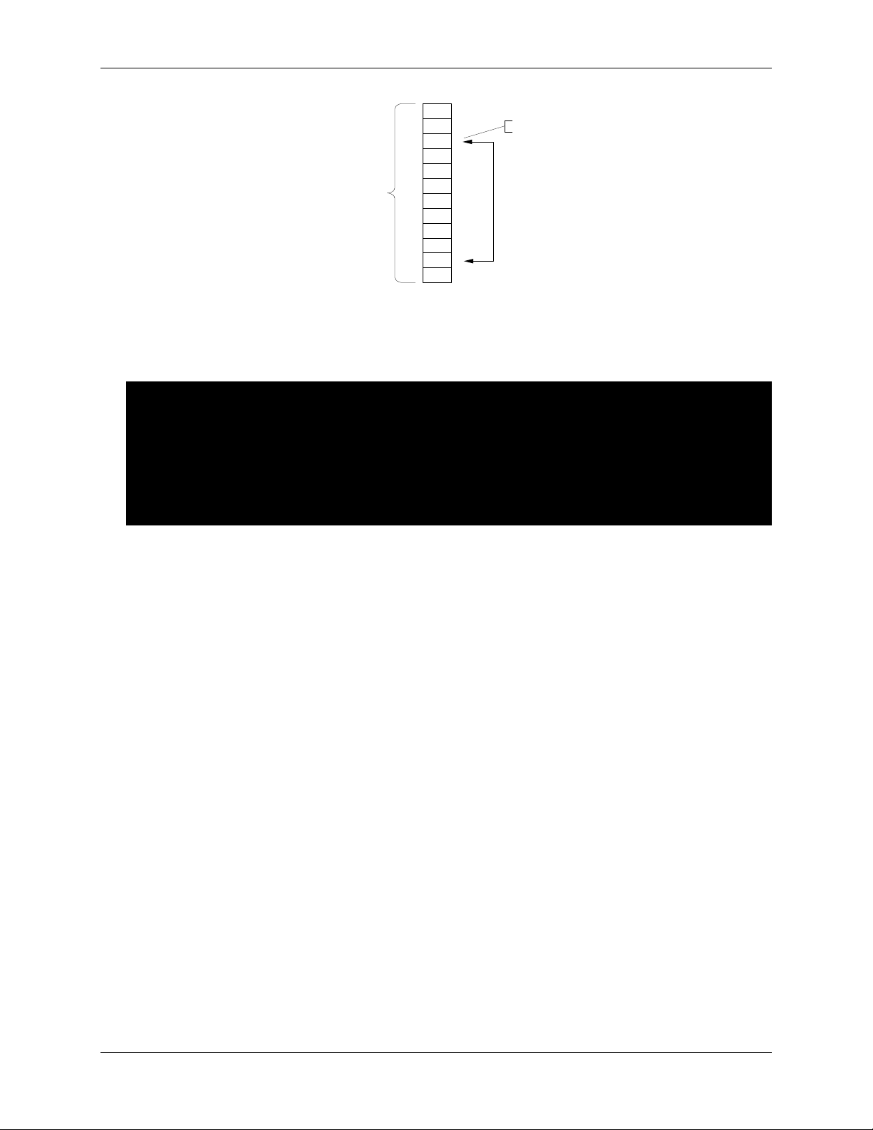
BitWindow: (R/W) This feature sets/returns the available data bits to be output and the LSB
position. The camera’s pixel data is processed at 12 bits internally, and can be output at 8,
10, or 12 bits per pixel depending on the LSB positioning. The LSB defines the least
significant bit to be output. This allows examination of a subset of the available output
dynamic range. The bit specified as the LSB will be assigned to bit 0 of the output data.
The output data will include bits from the specified bits ranging from LSB to LSB + (bitdepth-
1) of the internal data. If the bitdepth of the window specified is less than the selected bit
depth, the remaining most significant bits will be zero-filled. Min: 2048, Max: 3072
NOTE: Determined by data output formatting.
The bit configuration specified by this command is the input data to any additional output
data formatting created by the output interface. For example, the “system” bit depth can be
set to a bit depth of 10 with this command which will cause the camera to output 10 bits of
pixel data.
4411-0128, Rev. A 07/28/09 4
Page 9
MEGAPLUS GigE Vision Features Guide (Customer Edition)
Bit 0
Bit 1
Bit 2
Bit 3
Bit 4
Bit 5
Bit 6
Bit 7
Bit 8
Bit 9
Bit 10
Bit 11
Start Bit
BitDepth
Total
Bits
This provides a windowing function that enables the user to specify which of the available
data bits are output. The bit number specified for LSB is zero-based – i.e., the least
significant bit in an 8-bit word is bit 0 and the most significant bit is bit 7.
NOTES:
1. The maximum bit depth setting is “8” if using a single-head controller and
outputting “processed RGB data”.
2. The data is compressed into an integer and is broken into two characters. The
leftmost 8 bits express the bit depth in binary (8, 10, or 12) and the rightmost 8
bits express the LSB position of the bit depth.
Examples: 0x0804 represents 8 bits LSB in position 4
0x0A01 represents 10 bits LSB in position 1
.
BlueGain: (R/W) This feature sets/returns the blue analog gain value for the camera (or tap
where appropriate). The sensor tap is set by the SensorTapReadout feature. Min: 1, Max:
63
Brightness: (R/W) Reads/writes the brightness or offset for the currently active Head to the
specified value in DN counts. Min: 1, Max: 255
CamPixClkFrequency: (Read) Returns the current pixel clock frequency in MHz for the active
camera. Min: 0, Max: 40
CamPixClkSpeed: (R/W) The camera provides user-selection of clock speeds. The camera
supports more than one pixel clock selection. The camera provides the user with the option
to run the sensors at different speeds to accommodate variations in framegrabbers or
application requirements. The actual pixel clock frequency can be determined with the
CamPixClkFrequency. Low/High
4411-0128, Rev. A 07/28/09 5
Page 10

MEGAPLUS GigE Vision Features Guide (Customer Edition)
NOTES:
1. This feature is only active for configurations where all attached heads are
identical. Configurations that utilize mixed heads only support the factory default
pixel clock rate in order to accommodate the requirements of the unlike sensors.
2. Changing pixel clock speed causes the camera to perform initialization of the
timing generators and several associated functions for the new speed. For this
reason, it takes a few seconds for the camera to process the command and
respond.
3. Changing the pixel clock speed while a framegrabber is grabbing live data may
cause the framegrabber to timeout.
4. Some camera heads do not support dual-tap channel balance for two different
clock speeds. If this is true of your camera head, this command will change the
clock speed, but may return a warning status. At higher some clock rates, you
may see imbalance in the image when running in dual tap mode. Check with your
Redlake application engineer to see if your head can be calibrated for two
operation speeds.
ConsoleTempBot: (Read) This feature returns one of three health-monitoring temperatures
from the camera control console (i.e., controller). The value returned is the temperature of
the top of the console processor board. The value is in degrees Celsius. Min: -100, Max:
250
NOTE: For the single-head controller, the bottom and power supply temperature
readings share the same sensor.
ConsoleTempPS: (Read) This feature returns one of three health-monitoring temperatures
from the camera control console (i.e., controller). The value returned is the temperature of
the bottom of the console processor board. The value is in degrees Celsius. Min: -100, Max:
250
ConsoleTempTop: (Read) This feature returns one of three health-monitoring temperatures
from the camera control console (i.e., controller). The value returned is the temperature of
the power supply. The value is in degrees Celsius.Min: -100, Max: 250
DefectConceal: (R/W) Toggles defect concealment for the active camera head. Off/On
DoubleExposureTPD: (R/W) This feature sets/returns the transfer pulse delay for double
exposure trigger mode (Mode 4). The allowable range is 0.1 to 999 µsec in 0.1 µsec
intervals. However, due to CCD timing constraints, the minimum value that the CCD will
actually implement depends on the camera model. For the minimum integration time for your
camera, refer to the appropriate camera specification table in “Camera Component
Specifications” section in the MEGAPLUS User Manual. Min: 0.1 µsec, Max: 999 µsec
ExposureTimeMax: (Read) This feature returns the Value relating to the maximum exposure
time. This value varies based on changes in Binning, CamPixClkSpeed and
SensorTapReadout. Min: 0, Max 999
FlatFieldNormalization: (R/W) This feature controls whether the flat field gain and offset
correction for the currently selected head is active or not. When “on” all pixel values for the
sensor are corrected with the values specified in the normalization tables. A separate
correction table is maintained for each sensor. Checked/Unchecked
4411-0128, Rev. A 07/28/09 6
Page 11

MEGAPLUS GigE Vision Features Guide (Customer Edition)
GreenGain: (R/W) This feature sets/returns the analog gain value for the specified head (or tap
where appropriate). Head and sensor tap are set by previously defined individual
commands. Min: 1, Max: 63
HeadFanState: (R/W) This feature turns the head cooler fan on/off state for a camera with a
fan. On/Off
HeadSensorTargetTECTemp: (Read) This feature returns the temperature (in Celsius) of the
camera head sensor TEC. Min: -20, Max: 60
HeadTECState: (R/W) This feature turns the TEC on or off for the camera head sensor. The
TEC state must be set to Auto if you want to activate a target temperature setting entered
via the HeadSensorTECTargetTemp. Off/On/Auto
HeadTargetTECTemp: (R/W) This feature sets/returns the target temperature (in Celsius) of
the camera head sensor TEC. This target temperature setting will be only used if
HeadSensorTECState has set the TEC state to Auto. Min: -20, Max: 60
HeadTemperature: (Read) This feature returns the temperature (in Celsius) of the camera.
Used for cameras that do not contain a TEC. For cameras containing a TEC, refer to the
TEC-related commands (for example, HeadTECState). Min: -100, Max: 250
HeadsAttached: (Read) This feature queries the camera and returns the number of heads
currently attached to the console (controller). Min: 1, Max: 1
HeadsSupported: (Read) This feature returns the maximum number of heads that this console
can support. Min: 1, Max: 1
MechanicalShutter: (R/W) This feature sets/returns the state of the mechanical shutter. “0” =
locked closed; “1” = trigger activated; “2” = locked open. Min: 0, Max: 2
NOTE: Mechanical shutters are present in Princeton Instruments’ full frame Camera
Heads, the ES 1602/1603 and ES 3200. The mechanical shutter functions have no
effect on Camera Heads employing interline sensors.
Mode6Interval: (R/W) When operating in triggered Mode 6 (Periodic Interval), which causes
the camera to self-trigger an image repeatedly at a specified time interval (in milliseconds),
this feature is used to set/return the time period between triggers. The typical range is 1/Max
frame rate of the sensor to 5 minutes. Min: 1, Max: 32767
PixelClockFrequency: (Read) Returns the floating point value for the current pixel clock
frequency in MHz for the active camera. Min: 0, Max: 40
RedGain: (R/W) This feature sets/returns the red analog gain value for the camera (or tap
where appropriate). Camera and sensor tap are set by other defined individual features.
Min: 1, Max: 63
4411-0128, Rev. A 07/28/09 7
Page 12

MEGAPLUS GigE Vision Features Guide (Customer Edition)
Important Things to Know
The Triggered Integration Time value applies to all attached camera heads. This value
will be applied in trigger mode 0 (Edge Trigger, Asynchronous Reset), 6 (Periodic
Interval), or 7 (Overlapped Edge Mode) active.
This function controls triggered integration time only. When the camera is operating in
free-run (video) mode, integration time is controlled via the ExposureTimeAbs feature.
SensorTapReadout: (R/W) This feature sets/returns the mode to be used when reading pixel
data from the sensor. Currently supported mode selections include single tap and dual tap.
This mode applies to all sensors attached to the camera. If the sensors in the camera
heads do not support dual tap operation, the readout will be single tap and this command
will have no effect on operation. Not all camera heads will support dual tap readout. The
MEGAPLUS full-frame heads including the ES 1602*/3 and ES 3200 do not support dual tap
operation. The effect of this function in custom mixed-sensor configurations will be defined
per application. One= single tap/Two=dual tap
NOTE: Sensor tap readout configuration does not affect the camera's data output
configuration. When a sensor is read in dual tap mode, the two taps are interleaved in
the camera back into a single image stream. Not all camera heads will support dual
tap readout. The MEGAPLUS full-frame heads including the ES 1602*/3 and ES 3200
do not support dual tap operation.
StrobeDelay: (R/W) This feature sets/returns the delay between the time that the trigger signal
is received and the time that the strobe signal is output. Delay is in milliseconds. If a delay
of zero is specified, the strobe will be output immediately after receipt of the trigger. If a
delay period is specified that is longer than the integration time of the sensor (determined
either by programmed value or pulse width), the strobe will be output immediately at the end
of the integration period. Min: 0, Max: 999
StrobePolarity: (R/W) This feature sets/returns the output strobe signal polarity.
Negative/Positive
TriggerInputPolarity: (R/W) This feature sets/returns the trigger polarity setting for the
controller. A positive polarity means the trigger signal will be considered active when the
signal is in a high or true state. Negative polarity is the reverse - the trigger signal will be
considered active when the signal is in a low state. Negative/Positive
TriggerIntTime: (R/W) When operating in triggered modes that use a programmable integration
time, this command specifies the integration time that will be used for the triggered
exposure. This control offers a range of integration time values that can be beyond the
range available with the standard free-run sensor integration time. The specified integration
time will be applied to all Camera Heads when triggering is enabled and a trigger is
received. Note: In some trigger modes (for example, Mode 1) integration time is controlled
by other means, such as pulse width. In this case the Triggered Integration Time value has
no effect. Unit is milliseconds. Specified as floating point with 3 digits of fractional precision
(x.xxx) to provide 1 microsecond resolution. Range is 0.001 (1 µsec) to 10,000 msec (10
seconds) for trigger modes 0-6. For trigger mode 7, range is 0.010 (10 µsec) to 600,000 (10
minutes). Min: 0.01, Max: 600,000
*
ES 1602 has been discontinued.
4411-0128, Rev. A 07/28/09 8
Page 13

MEGAPLUS GigE Vision Features Guide (Customer Edition)
Triggered mode operation provides a larger range of integration times. Free-run
integration time is limited to one frame-readout time at the current clock rate.
TriggerState: (R/W) This feature turns triggering ON or OFF. When triggering is enabled
(checked), the camera will recognize and respond to trigger events in the manner dictated
by the trigger mode. When triggering is disabled (unchecked), all trigger signals will be
ignored and the camera will operate in a free-run video mode. Checked/Unchecked
TriggeringMode: (R/W) This feature sets/returns the trigger mode for the controller. Note: In
addition to setting the trigger mode, triggering must be enabled with the TriggerState
feature in order for triggered operation to take effect. EdgeControlled, LevelControlled,
DoubleExposureMode, PeriodicInterval, OverlappedEdge
TriggeringSource: (R/W) This feature specifies/returns the input source that will initiate the
trigger event. Sources can include: external trigger (via BNC on controller rear panel) or
software trigger. The software trigger command only applies to mode 0 (Edge Trigger,
Asynchronous Reset) and 7 (Overlapped Edge Mode). Use the TriggerSoftware feature to
cause a software trigger event. BNC/Software
WhiteBalanceAuto: (R/W) This feature sets the white balance for the currently selected head.
The system uses the default head value of 1. The camera will perform a semi-auto white
balance. Execute
WhiteBalanceBlue: (R/W) This feature sets/returns the white balance for the camera. The values
specified for blue is relative to green, which is the master color. The value for green is always
1.0. Min: 0, Max: 64
WhiteBalanceRed: (R/W) This feature sets/returns the white balance for the camera. The values
specified for red is relative to green, which is the master color. The value for green is always
1.0. Min: 0, Max: 64
4411-0128, Rev. A 07/28/09 9
Page 14

MEGAPLUS GigE Vision Features Guide (Customer Edition)
2.4 Device Information
Device Information provides description of the camera and its sensor. The device specific
information shown below for configuration attributes is for a MEGAPLUS EC11000 Color
camera and single-head GigE Vision controller as of 07/07/09. The intent is to provide examples
of what the user would see. Actual information will vary based on the camera and controller that
is being used.
AppVersion: (Read) Retrieves the firmware version of the application software. In this case, the
value is 504 which represents version 5.04#.
NOTE: The firmware version is expressed as an integer and should be divided by 100
to express the major and minor versions of the firmware.
DeviceID: (Read) 1100015
DeviceManufacturerInfo: (Read) Release-1.2 (00080602)
DeviceModelName: (Read) MEGAPLUS EC11000 Color
DeviceScanType: (R/W) This feature specifies the scan type of the sensor. Typically, this
feature is not writable. But some cameras might allow switching between linescan and
areascan. DeviceScanType can take any of the following values:
• Areascan: 2D sensor
• Linescan: 1D sensor
DeviceUserID: (R/W) User-programmable ID
DeviceVendorName: (Read) Princeton Instruments
DeviceVersion: (Read) Version 1.6 (02.00.03)
FpgaVersion: (Read) Retrieves the firmware version of the Fpga firmware. 1268
NOTE: The version is expressed as an integer and should be divided by 100 to
express the major and minor versions of the firmware.
HeadSerialNumber: (Read) Camera serial number. 110358
SerialVersion: (Read) Retrieves the firmware version of the Serial port communications
software. 143
NOTE: The version is expressed as an integer and should be divided by 100 to
express the major and minor versions of the firmware.
2.5 Image Size Control
Image Size Control lists all features controlling the size of the transmitted image.
BinningHorizontal: (R/W) This feature represents the number of horizontal photo-sensitive
cells that must be combined (added) together. This has the net effect of increasing the
intensity (or signal to noise ratio) of the pixel and reducing the horizontal resolution (width) of
the image. A value of 1 indicates that no horizontal binning is performed by the camera.
BinningVertical: (R/W) This feature represents the number of vertical photo-sensitive cells that
must be combined (added) together. This has the net effect of increasing the intensity (or
signal to noise ratio) of the pixel and reducing the vertical resolution (height) of the image. A
value of 1 indicates that no vertical binning is performed by the camera.
4411-0128, Rev. A 07/28/09 10
Page 15

MEGAPLUS GigE Vision Features Guide (Customer Edition)
Height: (R/W) This feature represents the actual image height transmitted by the camera (in
pixels). Min: 1, Max: Sensor height
PixelCoding: (Read) This feature indicates the coding of the pixels in the image. Raw gives the
data in the native format of the sensor. It is mainly used for Bayer sensor. This value must
always be coherent with the PixelFormat feature.
PixelColorFilter: (Read) This feature indicates the type of color filter that is applied to the
image. This value must always be coherent with the PixelFormat feature.
PixelFormat: (R/W) This feature indicates the format of the pixel to use during the acquisition.
Values of the enumeration and the pixel formatting correspond to the GigE Vision
specification. It contains all the information provided by PixelCoding, PixelSize,
PixelColorFilter but combined in one single value.
PixelSize: (Read) This feature indicates the total size in bits of a pixel of the image. This value
must always be coherent with the PixelFormat feature.
SensorDigitzationTaps: (R/W) This feature represents the number of digitized samples output
simultaneously by the camera A/D conversion stage.
SensorHeight: (Read) This feature indicates the effective height of the sensor in pixels. Its
value must be greater than 0. For linescan sensor, this value is 1. Min:0, Max: full height of
the sensor.
SensorWidth: (Read) This feature indicates the effective width of the sensor in pixels. Min:0,
Max: full width of the sensor.
TestImageSelector: (R/W) This feature selects the type of test image that is transmitted by the
camera. TestImageSelector can take any of the following values:
• Off: Image is coming from the sensor.
• IPEnginetestPattern: Image is filled with a repetitive pattern.
Width: (R/W) This feature represents the actual image width transmitted by the camera (in
pixels). Min: 1, Max: Sensor width
4411-0128, Rev. A 07/28/09 11
Page 16

MEGAPLUS GigE Vision Features Guide (Customer Edition)
This page intentionally left blank.
4411-0128, Rev. A 07/28/09 12
Page 17
GigE Feature Name
Page Number
ActiveHead (R/W)
4
AppVersion (Read)
10
Binning (R/W)
4
BitWindow (R/W)
4
BlueGain (R/W)
5
Brightness (R/W)
5
CamPixClkFrequency (Read)
5
CamPixClkSpeed (R/W)
5
ConsoleTempBot (Read)
6
ConsoleTempPS (Read)
6
ConsoleTempTop (Read)
6
DefectConceal (R/W)
6
DoubleExposureTPD (R/W)
6
ExposureTimeAbs (R/W)
3
ExposureTimeMax (Read)
6
FlatFieldNormalization (R/W)
6
FpgaVersion (Read)
10
GainAbs (R/W)
4
Gamma (R/W)
4
GammaState (R/W)
4
GreenGain (R/W)
7
HeadFanState (R/W)
7
HeadsAttached (Read)
7
HeadSensorTargetTECTemp
7
HeadsSupported (Read)
7
HeadTargetTECTemp (R/W)
7
HeadTECState (R/W)
7
HeadTemperature (Read)
7
MechanicalShutter (R/W)
7
Mode6Interval (R/W)
7
RedGain (R/W)
7
SensorDigitizationTaps (R/W)
11
SensorHeight (Read)
11
SensorTapReadout (R/W)
8
SensorWidth (Read)
11
SerialVersion (Read)
10
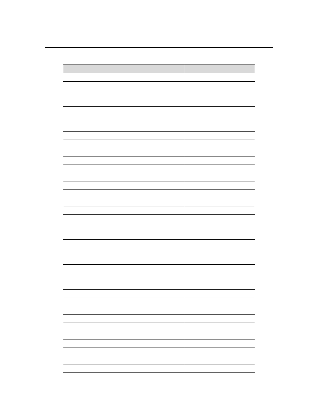
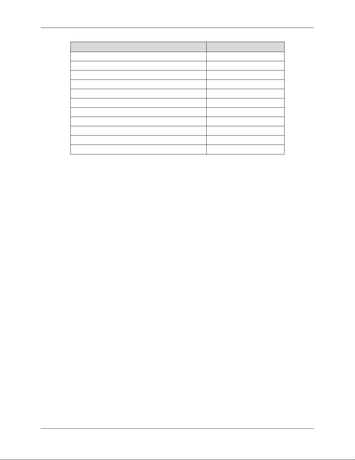
Appendix A – Alphabetical Listing of GigE Features
4411-0128 Rev. A 07/28/09 13
Page 18
MEGAPLUS GigE Vision Features Guide (Customer Edition)
GigE Feature Name
Page Number
StrobeDelay (R/W)
8
StrobePolarity (R/W)
8
TriggeringMode (R/W)
9
TriggeringSource (R/W)
9
TriggerInputPolarity (R/W)
8
TriggerIntTime (R/W)
8
TriggerSoftware (Write)
3
TriggerState (R/W)
9
WhiteBalanceAuto
9
WhiteBalanceBlue (R/W)
9
WhiteBalanceRed (R/W)
9
4411-0128, Rev. A 07/28/09 14
Page 19

4411-0128, Rev A. 7/28/09.
Revision History
4411-0128 Rev. A 07/28/09 15
Page 20

MEGAPLUS GigE Vision Features Guide (Customer Edition)
This page intentionally left blank.
4411-0128, Rev. A 07/28/09 16
 Loading...