

Page 1
Safety Information……………………………………...………………3
Specifications………………………………………...…………………4
Main Power Connection…………………………...…………………..5
DMX-512 Connection……………………………..…………………...5
Rigging the Fixture……………………………….…………………….6
Main Control Menu……………..…………………………………..….6
DMX Profile.................................................................................... 8
Cleaning & Maintenance...............................................................13
Parts List.......................................................................................13
USER MANUAL
Table of Contents
Page 2

Page 3
Check that the unit has not been damaged during transport
Protection Against Fire
1. Maintain a minimum of 1 foot distance from any type of flame.
3. Replace fuse only with the specified type and rating.
4. Do Not install the unit to close to a heat source.
5. Make sure cable are properly secured away from unit movement.
6. Maximum surface operating temperature 104º.
Protection Against Fire
1. Disconnect power before lamp replacement or servicing.
2. For connection to main power supply proceed to page 6.
3. This unit must be earthed. (electronically grounded)
4. Do not expose unit to rain or moisture.
Protection Against Mechanical Hazards
1. Use safety chain when hanging unit.
2. Use quality clamps or bolts when positioning unit
3. Do not open unit risk of electrical shock.
3
Page 4
Specifications
Part Numbers
Fixture Lamp Flight Case
1125- AXIS QD7 LOSRAM–12W RGBWLED P-1125 DUALCASE
Mechanical Specifications
Pan: 540° Tilt: 270°
DMX Connectors: 3-pin and 5-pin XLR connectors
Thermal: Maximum ambient temperature 100° F
Maximum surface temperature 130° F
Fastening System: 1 Removable mount
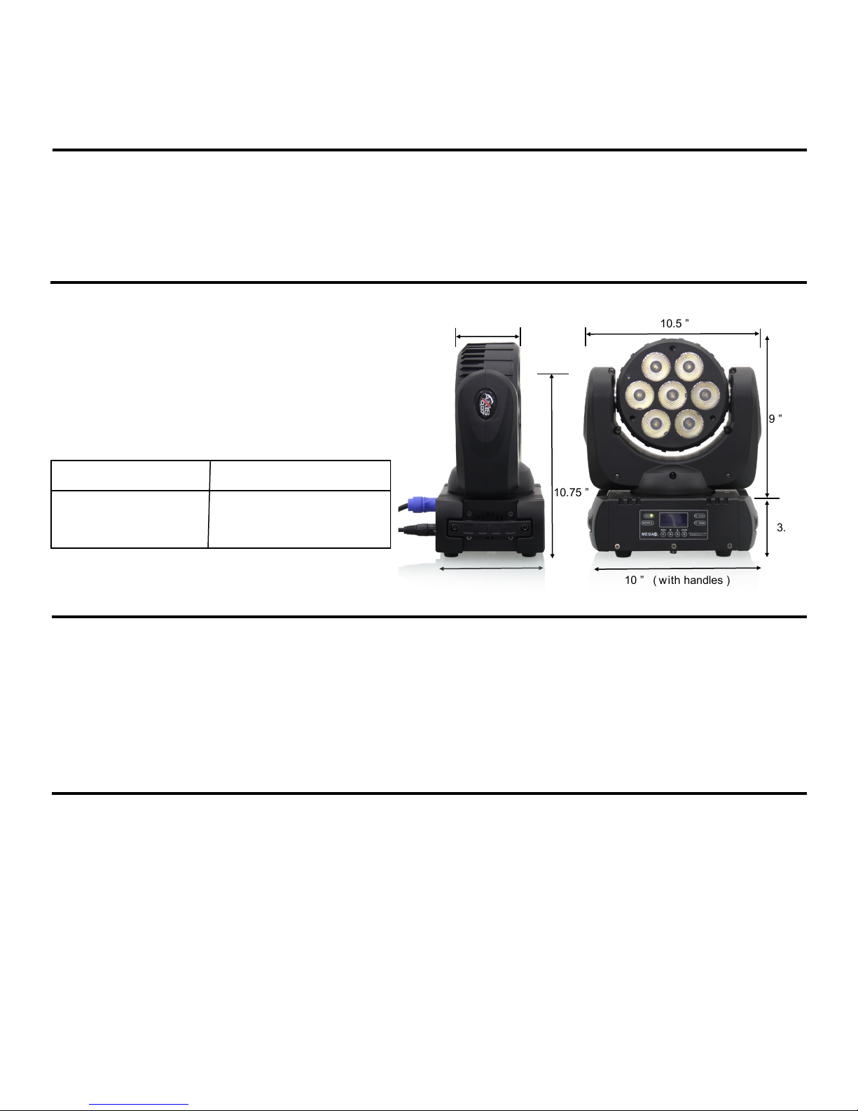
3.75 ”
10.5 ”
9”
Fixture Packaged for Shipping
Size: 10.5” x 96.5 x 12.5”
Weight: 12 lb
Size: 12.5” x 9” x 13.5”
Weight: 13.5lb
Electrical Specifications
Power supply: Auto Switch100V-240V 50/60 HZ
Power consumption: Amps 1.45
Watts 106
Ballast: Electronic
LAMP: 7X 12W RGBW LED’s
Electromechanical Effects
LED Control: Individual control of each LED
Shutter: Electronic Lamp strobe of lamp 18 flash per second
10.75 ”
3.5 ”
6.5 ”
10 ” ( with handles )
4
Page 5
Main Power Connection
Caution!
1. Do not connect fixture to a dimmer system.
2. This unit must be earthed. (electronically grounded)
3. Replace fuse only with the specified type and rating.
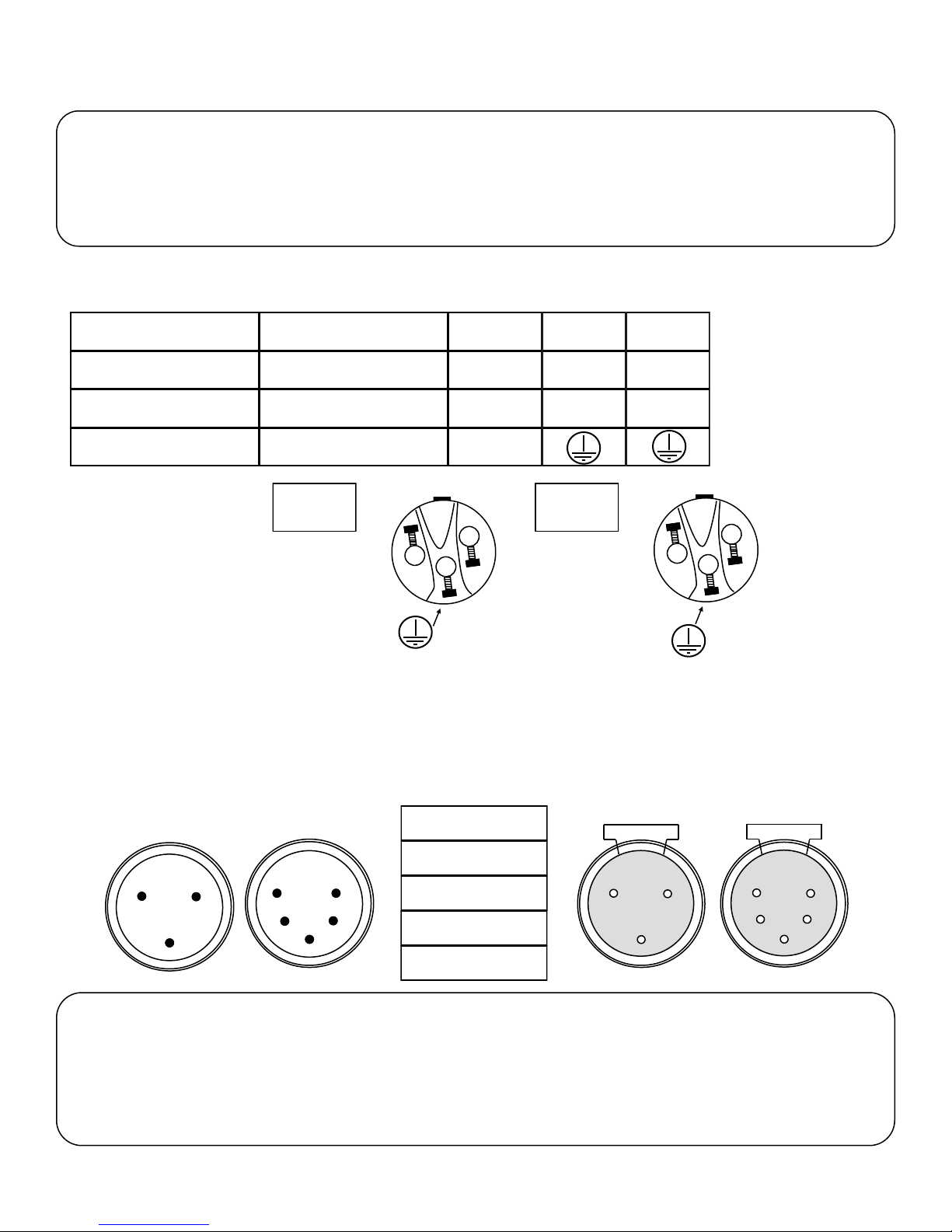
This device is equipped with a auto switching power supply that will allow you to work from 100V-240V 50/60Hz
The occupation of the connection-cable is as follows:
Cable (USA) Cable (EU) Pin 110V
Black Brown
White
Green
Light Blue
Yellow/Green
110V
Connec-
N
Live
Neutral
Ground
L
L
N
220V
Connec-
220V
L
L
L
L
DMX-512 Connection
The fixture is equipped with 3 pin and 5 pin XLR Sockets for DMX input and output. The sockets are wired in parallel.
Only use a shielded twisted pair cable designed for RS-485 and 3 pin or 5 pin XLR plugs and connectors in order to connect the controller with the fixture or the fixture with another.
DMX—input
1
2
3
1
2
3
Caution!
At the last fixture the DMX signal needs to be terminated with a terminator. Solder a
120 Ohm resistor between the (-) and the (+) signal into a 3 pin or 5 pin XLR plug
and plug it in to the last fixture on the signal run. Pre-manufactured terminator plugs
are available for purchase from your Mega-Lite dealer (HOS-DMXT).
DMX—output
1. Shield
2. Signal (-)
5
4
3. Signal (+)
4. N/A
2
1
3
5
4
1
2
3
5. N/A
5
Page 6
Rigging the fixture
Caution!
1. The installations must be carried out by an authorized dealer or trained professional.
2. Unit may cause severe injures if you have doubts concerning the safety do not install.
3. Unit is to be 24inches away from flammable materials (decoration material)
4. Use high quality installation equipment to hang unit.
When rigging a unit it is very important that you follow common safety procedures. Rigging requires extensive experience including but not limited to calculating working loads, material being used and periodic safety inspections. If you
lack these qualifications, do not attempt the installation yourself, instead use a professional structural rigger.
When rigging the unit always be secured with a secondary safety attachment. The installation location of the projector
has got to be built in the way that it can hold 10 times the weight for 1 hour with out any damage. Installation should be
checked at least one time a year by a skilled person.
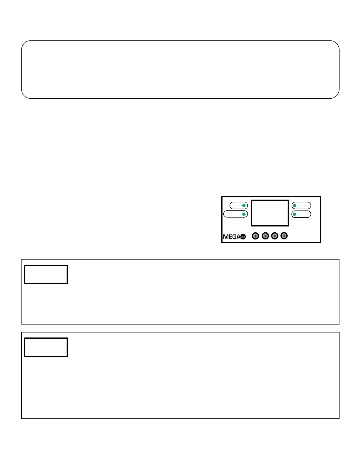
Main Control
The control board on the fixture base is your interface to access and
control all the functions on the unit. Its LED display gives you a code
view of the options and functions. The following will explain each function and its options.
DMX
MASTER
SLAVE
SOUND
—DMX512—
ADDR:001
>Work Mod
DMX 512
MENU ▲ ▼ ENTER
5718 Kenwick St
San Antonio TX 78238
800-460-MEGA
www.mega-lite.com
This function allows you to set your DMX Start Channel. First make sure you
have a proper DMX connection from your controller using the 3 or 5 pin XLR connection. If there is no DMX connection the display will flash and read No DMX
ADDR:001. If there is proper DMX connection the display will be solid on and will
read DMX 515, there will also be a Green indicator light that will turn on.
To Set the DMX Start Channel press the ▲ then press Enter. Use the ▲ or ▼ to
select the desired DMX Start Channel and press Enter to confirm your setting.
DMX 512= This mode w ill allow you to oper ate the fixture with a DMX controller
Auto= This Function slows the unit to run a pres et program
Sound= On Sound Mode the fixtu re will trigger the preset program w ith the
ambient audio sensitivity.
To Set the Desired operational mode press the ▲ then Press Enter. Use the ▲
or ▼ to select the desired DMX Start Channel and press Enter to confirm your
setting.
6
Page 7
>Chan Mod
17CH
>Tool
DimmMod
>PT Sett
Xrevise
>Display
60S
>DimmMod
Smooth
>Xrevise
000
>Yrevise
000
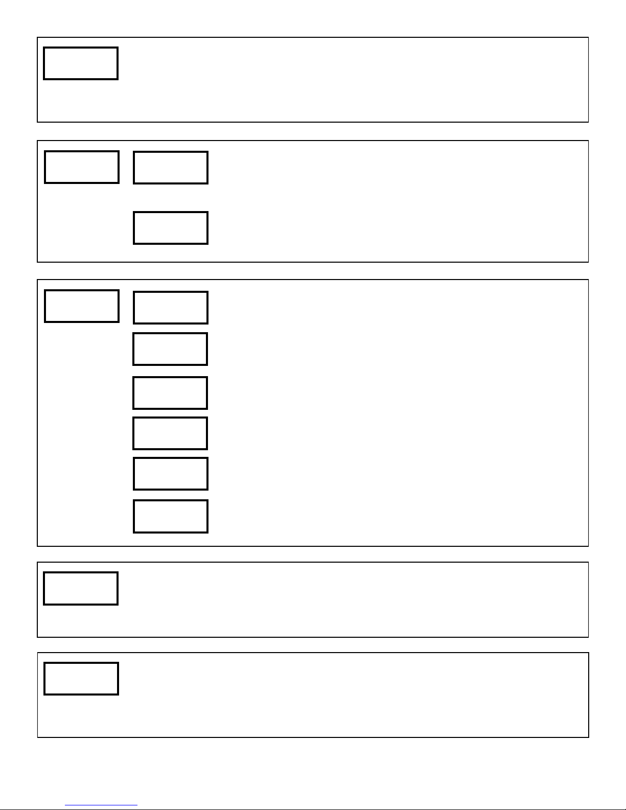
To set the desired operational channel mode press Enter. Use the ▲ or ▼ to
select the desired DMX profile operational mode from 6,17 or 37 and press Enter
to confirm your setting.
Note: Operational mode are located on Page 8 of the manual.
This function will give you access to the Display Control press Enter. Use the ▲
or ▼ to select the desired display operational Mode from turn off in 60 second or
stay On, press Enter to confirm your setting.
This function will give you access to the LED Dimming curve press Enter. Use
the ▲ or ▼ to select the LED dimming operational Mode from fast or smoth,
press Enter to confirm your setting.
If you wish to fine adjust your Pan extreme position press Enter. Use the ▲ or
▼ to select the desired Pan extreme position, press Enter to confirm your setting.
If you wish to fine adjust your Tilt extreme position press Enter. Use the ▲ or ▼
to select the desired Tilt extreme position, press Enter to confirm your setting.
>Control
CH01
>DmxLive
CH1
>Xreverse
NO
>Xreverse
NO
>XYspeed
fast
>XYfbsti
yes
To invert the Pan position press Enter. Use the ▲ or ▼ for yes or no to invert,
press Enter to confirm your setting.
To invert the Tilt position press Enter. Use the ▲ or ▼ for yes or no to invert,
press Enter to confirm your setting.
To adjust the speed of Pan & Tilt position press Enter. Use the ▲ or ▼ for slow,
normal and fast, press Enter to confirm your setting.
To adjust press Enter. Use the ▲ or ▼ for Yes or No, press Enter to confirm
your setting.
To access the control channels via display press Enter. Use the ▲ or ▼ to se-
lect the desired DMX Channel press Enter to access that function use the ▲ or
▼ to adjust the channel.
Note: Operational Channels are located on Page 10 of the manual.
To view the status of every channel via display press Enter. Use the ▲ or ▼ to
select the desired DMX Channel press Enter to view the channel status.
7
Page 8
>RGBWhit
WhitB
>Info
Version
>WhiteSW
on
>WhitR
255
>WhitG
255
>WhitB
255
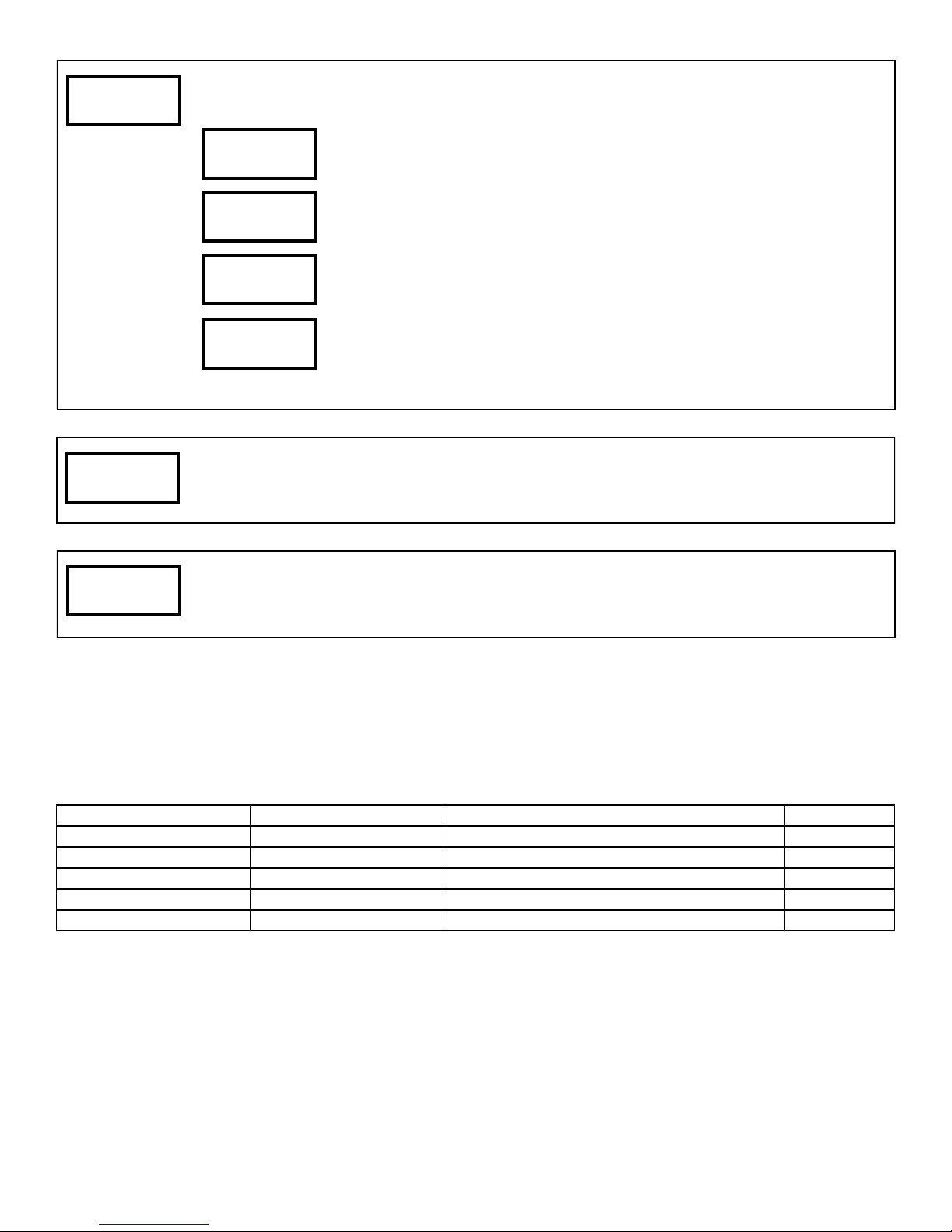
To adjust the white color balance Press Enter
If you wish to fine-tune the white color balance press Enter select On or Off press
Enter to confirm your setting.
To fine adjust the Red press Enter. Use the ▲ or ▼ to select the desired maxi-
mum intensity of the Red LED, press Enter to confirm your setting.
To fine adjust the Green press Enter. Use the ▲ or ▼ to select the desired max-
imum intensity of the Green LED, press Enter to confirm your setting.
To fine adjust the Blue press Enter. Use the ▲ or ▼ to select the desired maxi-
mum intensity of the Blue LED, press Enter to confirm your setting.
Press Enter to see the current software version
>Reset
NO
To reset the fixture press Enter. Use the ▲ or ▼ for Yes or No press Enter to
confirm your setting.
DMX Profile
Axis QD7 6 Ch Mode 1
1 Pan Pan Course 0-255
2 Tilt Tilt Course 0-255
3 LED Color Red 0-255
4 LED Color Green 0-255
5 LED Color Blue 0-255
6 LED Color White 0-255
8
Page 9
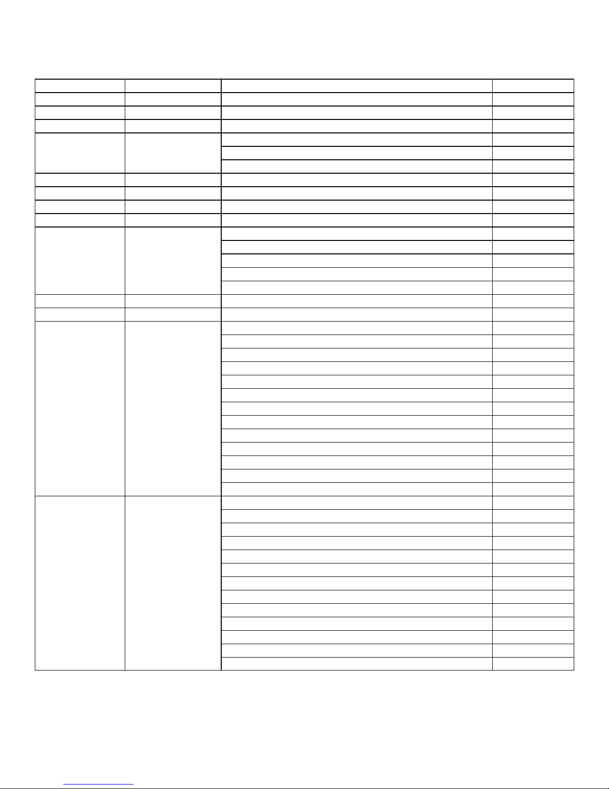
Axis QD7 17 Ch Mode 2
DMX Channel Function Description Value
1 Pan Pan Course 0-255
2 Pan Fine Pan Fine 0-255
3 Tilt Tilt Course 0-255
4 Tilt Fine Tilt fine 0-255
5 Pan/Tilt Speed
Slow 171-255
6 LED Color Red 0-255
7 LED Color Green 0-255
8 LED Color Blue 0-255
9 LED Color White 0-255
10 Shutter
Open 224-255
11 Dimmer Dimmer off to full 0-255
12 Color Fade Color Fade (slow to fast) 0-255
13 Color Preset
Red1-Green 2,3,4,5,6,7 221-255
14 Strobe Macro
Red Strobe 2,3,4,5,6,7,(slow to fast) 101-130
Green Strobe 2,3,4,5,6,7,(slow to fast) 131-160
Blue Strobe 2,3,4,5,6,7,(slow to fast) 161-190
White Strobe 2,3,4,5,6,7,(slow to fast) 191-220
All Strobe 1,2,3,4,5,6,7,(slow to fast) 221-255
Strobe (slow to fast) 32-95
Pulse (slow to fast) 96-159
Random Strobe (slow to fast) 160-223
Blue 1-Red 2,3,4,5,6,7 71-100
Blue 1-Green 2,3,4,5,6,7 101-130
Green1-Red 2,3,4,5,6,7 131-160
Red1-Blue 2,3,4,5,6,7 161-190
Green1-Blue 2,3,4,5,6,7 191-220
Red Strobe (slow to fast) 11-20
Green Strobe (slow to fast) 21-30
Blue Strobe (slow to fast) 31-40
White Strobe (slow to fast) 41-50
All Strobe Chase (slow to fast) 51-60
Random Strobe (slow to fast) 61-70
Fast 0-84
Mid 85-170
Closed 0-31
No Function 0-10
White 2700K 11-20
White 3200K 21-30
White 4300K 31-40
White 5600K 41-50
White 6500K 51-60
White 8000K 61-70
No Function 0-10
No Function 71-100
9
Page 10
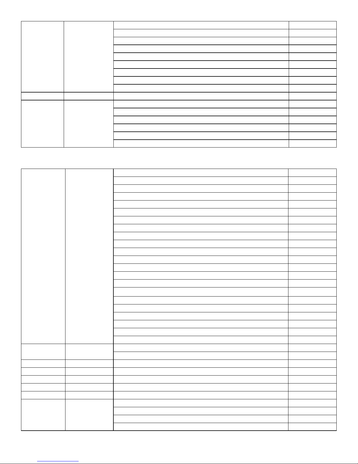
15 Macros
Color Chase Macro 8 221-255
16 Macros Speed Macro Speed (slow to fast) 0-255
17 Control
No Function 0-10
Color Chase Macro 1 11-40
Color Chase Macro 2 41-70
Color Chase Macro 3 71-100
Color Chase Macro 4 101-130
Color Chase Macro 5 131-160
Color Chase Macro 6 161-190
Color Chase Macro 7 191-220
No Function 0-79
All Motor Reset 80-99
Demo Program 1 100-150
Demo Program 2 151-200
Demo Program 3 201-250
No Function 251-255
Axis QD7 37 Ch Mode 3
1 Shutter
Open 245-255
2 Dimmer
Open 245-255
3 Pan Pan 0-255
4 Pan Fine Pan Fine 0-255
5 Tilt Tilt 0-255
6 Tilt Fine Tilt Fine 0-255
7 Pan/Tilt Speed Pan/ Tilt Speed (fast to slow) 0-255
8 Control
Random Open Pulse (fast to slow) 130-144
Random Closing Pulse (fast to slow) 150-164
Random Burst Pulse (fast to slow) 190-204
Strobe (fast to slow) 50-64
Open Pulse (fast to slow) 70-84
Closing Pulse (fast to slow) 90-104
Random Strobe (fast to slow) 110-124
Burst Pulse (fast to slow) 170-184
Wave Strobe (fast to slow) 210-224
Burst Strobe (fast to slow) 230-244
Closed 0-19
Open 20-49
Open 65-69
Open 85-89
Open 105-109
Open 125-129
Open 145-149
Open 165-169
Open 185-189
Open 205-209
Open 225-229
Dimmer 0-244
Lamp Control 0-9
Fixture Reset 10-14
Lamp Control 15-248
Single LED Control 249-255
10
Page 11
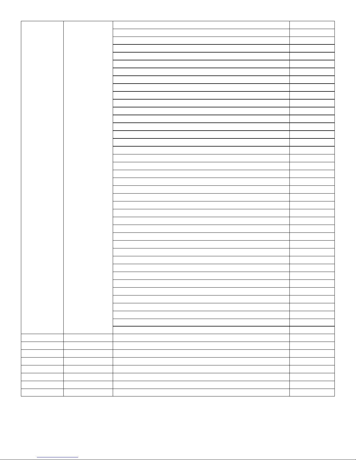
9 Color
Color Fade Clockwise (fast to slow) 180-201
Stop (will stop at last color) 202-207
Color Fade Counter Clockwise (fast to slow) 208-229
No Function 0-9
Moroccan Pink 10-14
Pink 15-19
Rose Pink 20-24
Follies Pink 25-29
Fuchsia Pink 30-34
Hot Pink 35-39
Congo Blue 40-44
Tokyo Blue 45-49
Deep Blue 50-54
Blue 55-59
Medium Blue 60-64
Double CT Blue 65-69
State Blue 70-74
Full CT Blue 75-79
Half CT Blue 80-84
Steel Blue 85-89
Lighter Blue 90-94
Light Blue 95-99
Medium Blue Green 100-104
Dark Green 105-109
Primary Green 110-114
Moss Green 115119
Fern Green 120-124
JAS Green 125-129
Lime Green 130-134
Spring Yellow 135-139
Deep Amber 140-144
Chrome Orange 145-149
Orange 150-154
Gold Amber 155-159
Millennium Gold 160-169
Flame Red 170-174
White 175-179
White 230-234
Random Color (fast to slow) 235-249
White 250-255
10 Red 1 Red Intensity 1 0-255
11 Green 1 Green Intensity 1 0-255
12 Blue 1 Blue Intensity 1 0-255
13 White 1 White Intensity 1 0-255
14 Red 2 Red Intensity 2 0-255
15 Green 2 Green Intensity 2 0-255
16 Blue 2 Blue Intensity 2 0-255
17 White 2 White Intensity 2 0-255
11
Page 12
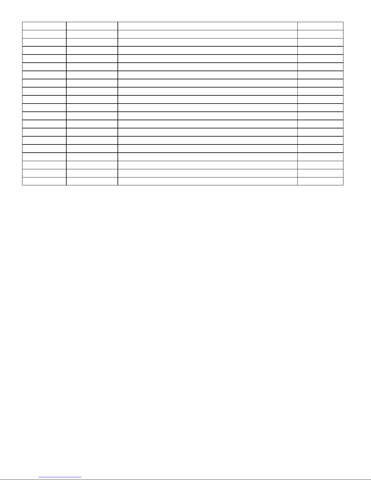
18 Red 3 Red Intensity 3 0-255
19 Green 3 Green Intensity 3 0-255
20 Blue 3 Blue Intensity 3 0-255
21 White 3 White Intensity 3 0-255
22 Red 4 Red Intensity 4 0-255
23 Green 4 Green Intensity 4 0-255
24 Blue 4 Blue Intensity 4 0-255
25 White 4 White Intensity 4 0-255
26 Red 5 Red Intensity 5 0-255
27 Green 5 Green Intensity 5 0-255
28 Blue 5 Blue Intensity 5 0-255
29 White 5 White Intensity 5 0-255
30 Red 6 Red Intensity 6 0-255
31 Green 6 Green Intensity 6 0-255
32 Blue 6 Blue Intensity 6 0-255
33 White 6 White Intensity 6 0-255
34 Red 7 Red Intensity 7 0-255
35 Green 7 Green Intensity 7 0-255
36 Blue 7 Blue Intensity 7 0-255
37 White 7 White Intensity 7 0-255
12
Page 13
Cleaning and maintenance
Installation Maintenance: The operator has to m ake sure that t he unit is operating saf ely and has the installa-
tions and electronics checked by an expert every 2 years.
The following points have to be considered during the inspection:
1) All screws used for installing the device or part of the device have to be tightly connected and must not be corroded.
2) There must not be any deformations on the housing, fixation and installation spots (ceiling, suspension, trussing).
3) Mechanically moved parts like axles and other must not show any traces of wearing and must not rotate with unbal-
ances.
4) The electronic power supply cables must not show any damages, material fatigue (e.g. porous cables) or sediments.
Further instructions depending on the installation spot and usage have to be adhered by a skilled installer and any
safety problems have to be removed.
Disconnect from mains before starting maintenance operation!
Caution Danger to life!
We recommend a frequent cleaning of the device. Please use a moist, lint free cloth. Never use alcohol or solvents!
1) The objective lens will require periodic cleaning on usage and environment. Environment with foggers will require
more periodic cleaning as fog fluid tends to build up residues, reducing the light output.
2) The cooling-fans should be cleaned monthly. DO NOT blow high pressure air into fans as incorrect rotation can
damage the fans operation.
3) The lenses may be cleaned with soft brush using soapy water.
4) The interior of the fixture should be cleaned using a vacuum.
5) We recommend proper lubrication of the motor wheel. The quantity of the oil must not be excessive in order to avoid
oil run outs when motor wheel rotates
Note: There is no serviceable parts i nsid e the dev ice except for the fuse. Maintenance and serv ice op erations
are to be carried out by authorized dealers.
Replacing the fuse: Only replace the fu se with the same typ e and rating.
Replacing the power cable: If the power cable of this device becom es damaged, it has to be r eplaced by aut hor-
ized dealers only
Should you have further questions , please contact your dealer.
Parts List
P-1125 4 Axis QD7 Case
1125-LEDMOD LED Module
1125-PS Power Supply
1125-DR LED Driver
1125-MPCB Main PCB/ Display Card
1125-FAN Fan 60mm
1125-CM Clamp Mount
1125-PTS Pan & Tilt Sensor
1125-HANB Handle Set
1125-ARMB Arm Body Set
1125-DISB Display Body Set
1125-HEADB Head Body Set
13
Page 14

Warranty Information
Warranty Conditions
• Unless otherwise stated in writing, your product is covered by a one year parts and labor limited warranty.
• LEDs are not guaranteed to match in color temperature or output.
• It is the owner’s responsibility to furnish receipts or invoices for verification of purchase, date, and reseller or distributor.
If purchase date cannot be provided, date of manufacture will be used to determine warranty period.
• GOODS RETURNED UNDER WARRANTY MUST FOLLOW THE PROPER AUTHORIZATION PROCEDURE AND
MUST BE ACCOMPANIED BY A COPY OF THE ORIGINAL INVOICE
• Goods repaired under warranty will be returned to the owner with the freight prepaid by MSI via the most economical
means of shipment
• REPAIR OR REPLACEMENT AS PROVIDED FOR UNDER THIS WARRANTY IS THE EXCLUSIVE REMEDY OF
THE CONSUMER. MEGA SYSTEMS INC. MAKES NO WARRANTIES, EXPRESS OR IMPLIED, WITH RESPECT TO
ANY PRODUCT, AND MEGA SYSTEMS SPECIFICALLY DISCLAIMS ANY WARRANTY OF MERCHANTABILITY OR
FITNESS FOR A PARTICULAR PURPOSE. MEGA SYSTEMS SHALL NOT BE LIABLE FOR ANY INDIRECT, INCIDENTAL OR CONSEQUENTIAL DAMAGE, INCLUDING LOST PROFITS, SUSTAINED OR INCURRED IN CONNECTION WITH ANY PRODUCT OR CAUSED BY PRODUCT DEFECTS OR THE PARTIAL OR TOTAL FAILURE OF ANY
PRODUCT REGARDLESS OF THE FORM OF ACTION, WHETHER IN CONTRACT, TORT (INCLUDING NEGLIGENCE), STRICT LIABILITY OR OTHERWISE, AND WHETHER OR NOT SUCH DAMAGE WAS FORESEEN OR UNFORESEEN.
• Warranty is void if the product is misused, damaged, modified in any way, or for unauthorized repairs or parts. This
warranty gives you specific legal rights, and you may also have other rights which vary from state to state.
Ph 210-684-2600 Fax 210-855-6279
www.mega-lite.com / [email protected]
Mega-Lite
5718 Kenwick St
San Antonio, TX 78238
 Loading...