

Page 1

Page 2

Page 3
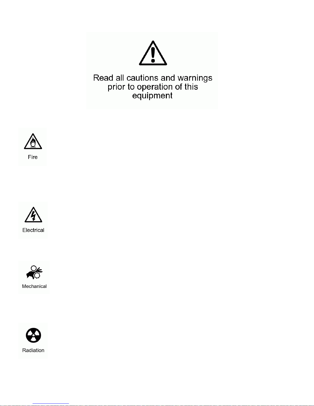
Check that the unit has not been damaged during transport
Protection Against Fire
1. Maintain a minimum of 1 foot distance from any type of flame.
2. This equipment is designed to be used only with the following lamp:
1 MSR 575/2
2 MDS 575
3.NSK 575
3. Replace fuse only with the specified type and rating.
4. Do Not install the unit to close to a heat source.
5. Make sure cable are properly secured away from unit movement.
6. Maximum surface operating temperature 80º.
Protection Against Fire
1. Disconnect power before lamp replacement or servicing.
2. For connection to main power supply proceed to page 4.
3. This unit must be earthed. (electronically grounded)
4. Do not expose unit to rain or moisture.
Protection Against Mechanical Hazards
1. Make sure head movement is not blocked.
2. Use safety chain when hanging unit
3. Unit surface may reach high temperature. Allow about 5 minutes after lamp has been turned off be-
fore moving.
4. Replace lamp before it exceeds the lamp life.
Protection Against UV Radiation
1. Do not look directly at the lamp when cover are off and lamp is on.
2. Do not start unit with out lamp covers or if the protection screens, or ultraviolet filters.
3
Page 4
Technical Features
Part Numbers
Fixture Lamp Flight Case
1010 - AXIS 500 L-MSR575/2 - Phillips MSR575/2 P-1010DUALCASE
L-MSD575 –Phillips MSD 575
L-NSK575
Mechanical Specifications
Pan: 540° Tilt: 270°
DMX Connectors: 3-pin XLR connectors
Reflector: Glass reflector with cold mirror coating
Thermal: Maximum ambient temperature 35°
Maximum surface temperature 80°
Mounting Points: 4 pairs of L-turn locks
Fastening System: 2 quick clamp release
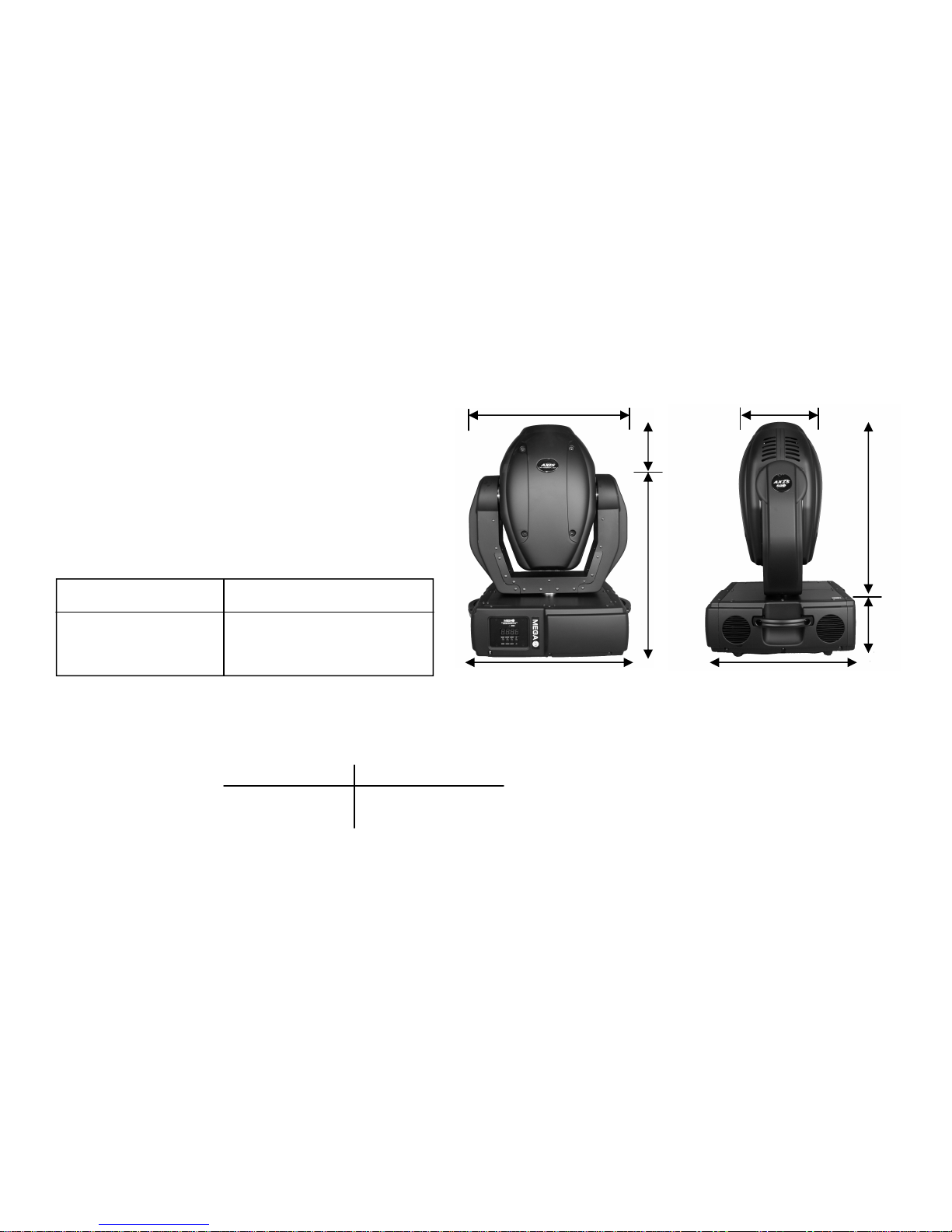
5.5”
8” 18.75”
20”
Size
in: 20”L x 17”W x 26”H
weight: 78.lb 35.40kg
Packaged for Shipping
in: 22”L x 22”W x 27.5”H
weight: 93 lb 42.25kg
20” W/ Handles
Electrical Specifications
Lamp: MSR 575/2—N SK575 MSD 575 (optional)
Light output: 12,000 ANSI lumen s 10,000 ANSI lumens
Lamp life: 500-750 hours 3,000 hours
Color temperature: 6200K 5600K
Power Consumption: 120V 50/60hz
Lamp Life: 700 hours
Base: GX-9.5
Control: Automatic and remote lamp on/off
Ballast: Magnetic
Electromechanical Effects
20.5”
6”
17”
Focus: Motorized focus
Zoom: Motorized multi-step zoom (15° , 18° and 22°)
Prism: 3-Facet prism rotating in both directions at different speeds
Iris: Motorized
Dimmer / Shutter: Full range dimming and variable strobe effect
4
Page 5
Main Power Connection
Caution!
1. Do not connect fixture to a dimmer system.
2. This unit must be earthed. (electronically grounded)
3. Replace fuse only with the specified type and rating.
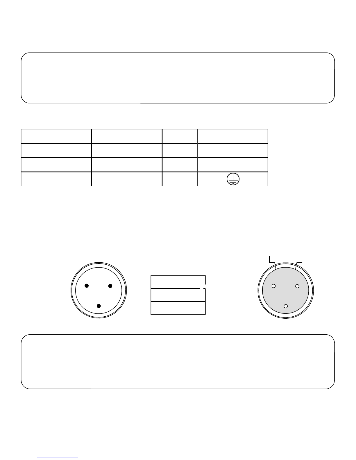
The occupation of the connection-cable is as follows:
110V 50/60hz Connection
Cable (USA) Cable (EU) Pin International
Black Brown
White
Green
Light Blue
Yellow/Green
Live
Neutral
Pin
L
N
DMX-512 Connection
The fixture is equipped with 3 pin XLR Sockets for DMX input and output. The sockets are wired in parallel. Only use a shielded
twisted pair cable designed for RS-485 and 3 pin XLR plugs and connectors in order to connect the controller with the fixture or
the fixture with another.
DMX—input
2
1
1. Shield
2. Signal (-)
3
3. Signal (+)
DMX—output
2
1
3
Caution!
At the last fixture the DMX signal needs to be terminated with a terminator. Solder a 120
Ohm resistor between the (-) and the (+) signal into a 3 pin XLR plug and plug it in to the
last fixture on the signal run. Pre-manufactured terminator plugs are available for
purchase from your Mega-Lite dealer (HOS-DMXT).
Note: After switching the unit on it will automatically detect whether DMX 512 data is received or not . If it is not receiving DMX
512 data the display screen will start to flash “A001” with the set address number. Once it receives proper DMX 512 signal the
display will stop flashing.
5
Page 6
Lamp Replacement
Caution!
1. Disconnect power before you begging.
2. Allow 15min for the unit and lamp to cool.
3. Do not touch lamps glass envelope with your fingers. If this happens clean with alco-
hol / to remove oils.
Lamp Placement
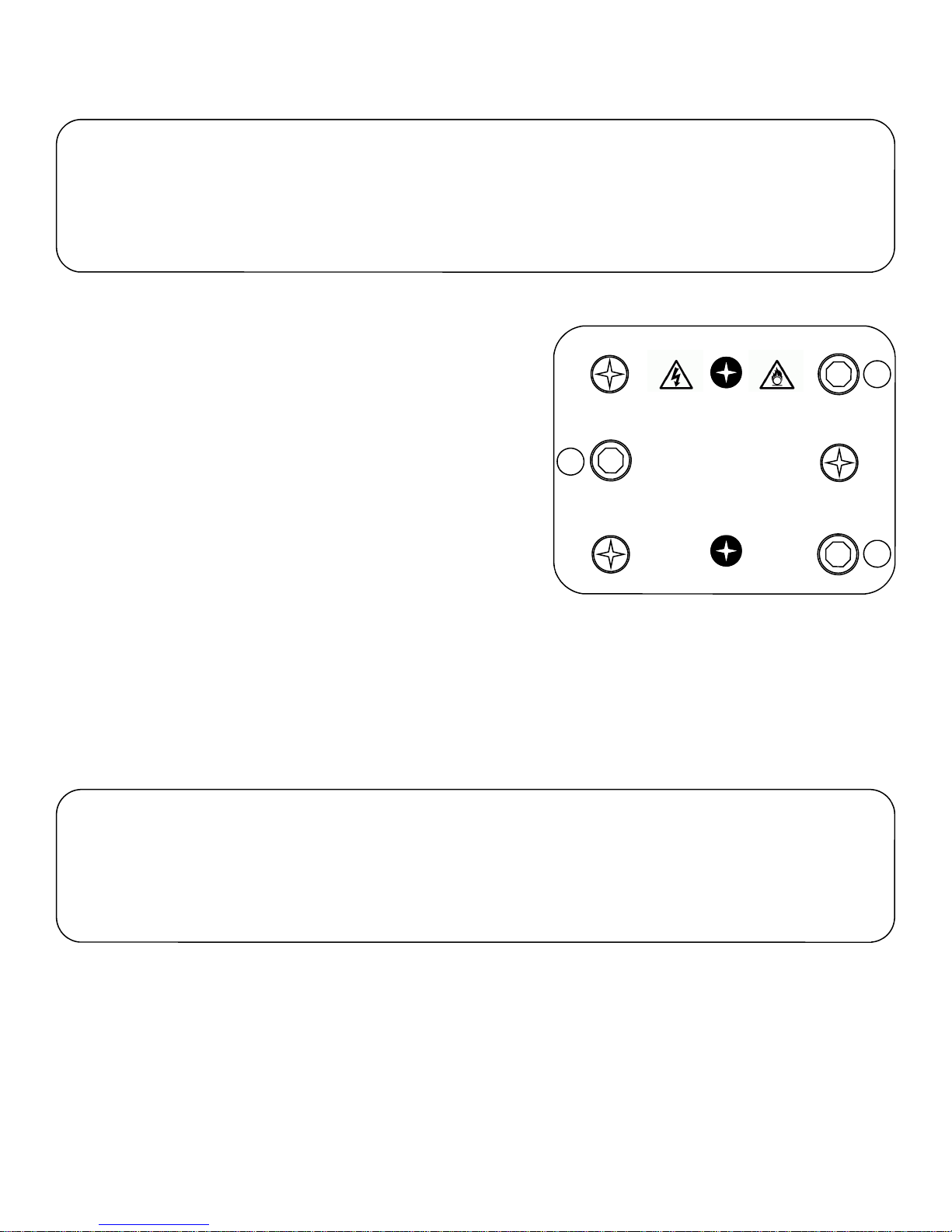
To insert the lamp MSR 575/2, NSK575 or MSD 575. Us a Phillips
screwdriver to unscrew the bolts marked XY and Z. Carefully pull out
the cover with the lamp socket and remove the old lamp from the
socket. Make a note that there is a large and small pole insert the new
lamp into corresponding socket.
Do not install a higher wattage lamp this will void your warranty. Please
note the light bulb manufactures warnings. Do not touch the bulb with
bare hands. Close lamp cover while making sure that the cables are
not pinched or touching the lamp. Tighten the XYZ screws.
Before striking the lamp reset the lamp timer by going to the LAti sec-
tion of your display screen. In order to reset the lamp counter to 0 you
have to hold the up and down button and press the enter button.
X
B
Z
Remove the screws X, Y, and Z for re-lamping
Disconnect the fixture from AC power before re-lamping.
Lamp is hot! Risk of fire! Protect hands and eyes.
Wait at least 15min. Before opening covers
Minimum distance from flammable material d=0.7m.
Adjust lamp position by turning screws A,B and C
WARNING!
And removing lamp from fixture.
Maximum room temperature t=40ºC
Exterior surface temperature T=80ºC.
Not for domestic use.
A
Y
C
Lamp Adjustment
Due to the difference between lamps. Fine adjustment may improve light performance. You will need to strike the lamp and set
the light so the optical path is clear. You will need to turn the screws A,B and C one after another a slight turn clockwise and
counter clockwise until you set the hot spot of the light in the center of the image. If no hot spot can be seen then set the lamp till
the light is evenly distributed.
Rigging the fixture
Caution!
1. The installations must be carried out by an authorized dealer or trained professional.
2. Unit may cause severe injures if you have doubts concerning the safety do not install.
3. Unit is to be 24inches away from flammable materials (decoration material)
4. Use high quality installation equipment to hang unit.
When rigging a unit it is very important that you follow common safety procedures. Rigging requires extensive experience includ-
ing but not limited to calculating working loads, material being used and periodic safety inspections. If you lack these qualifica-
tions, do not attempt the installation yourself, instead use a professional structural rigger.
When rigging the unit always be secured with a secondary safety attachment. The installation location of the projector has got to
be built in the way that it can hold 10 times the weight for 1 hour with out any harming. Installation should be checked at least
one time a year by a skilled person.
6
Page 7
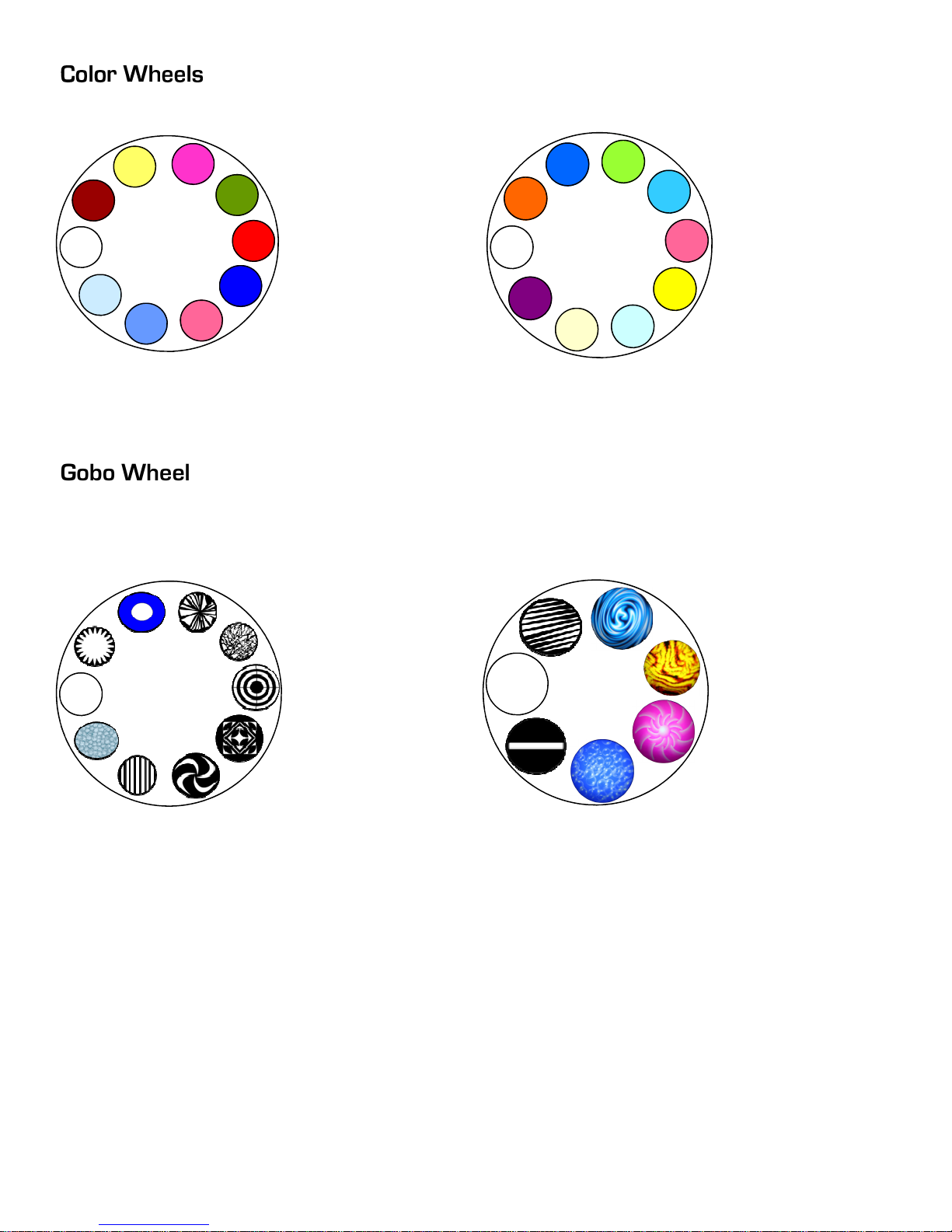
Color Wheel 1
Gobo Wheels
Gobo Wheel 1 Fixed
1: Open
2: Deep Red
3: Yellow
4: Magenta
5: Green
6: Red
7: Blue
8: Pink
9: Cyan
10: Light Blue
1: Open
2: Mega Gear
3: Blue Halo
4: Broken Glass
5: Rock
6: Circles
7: Every Way
8: Boomerangs
9: Bars
10: Pebbles
Color Wheel 2
Gobo Wheel 2 Rotating
1: Open
2: Orange
3: Blue
4: Light Green
5: Cyan
6: Magenta
7: Yellow
8: CTB
9: CTO
10: Deep Purple
1: Open
2: Metal Curtin
3: Velvet Ripel
4: Hell Cloud
5: Magenta Sun
6: Bubbles
7: Bar
Dichroic Glass Gobo: Diameter 27 mm Image 24 mm Thickness 4 mm max
7
Page 8
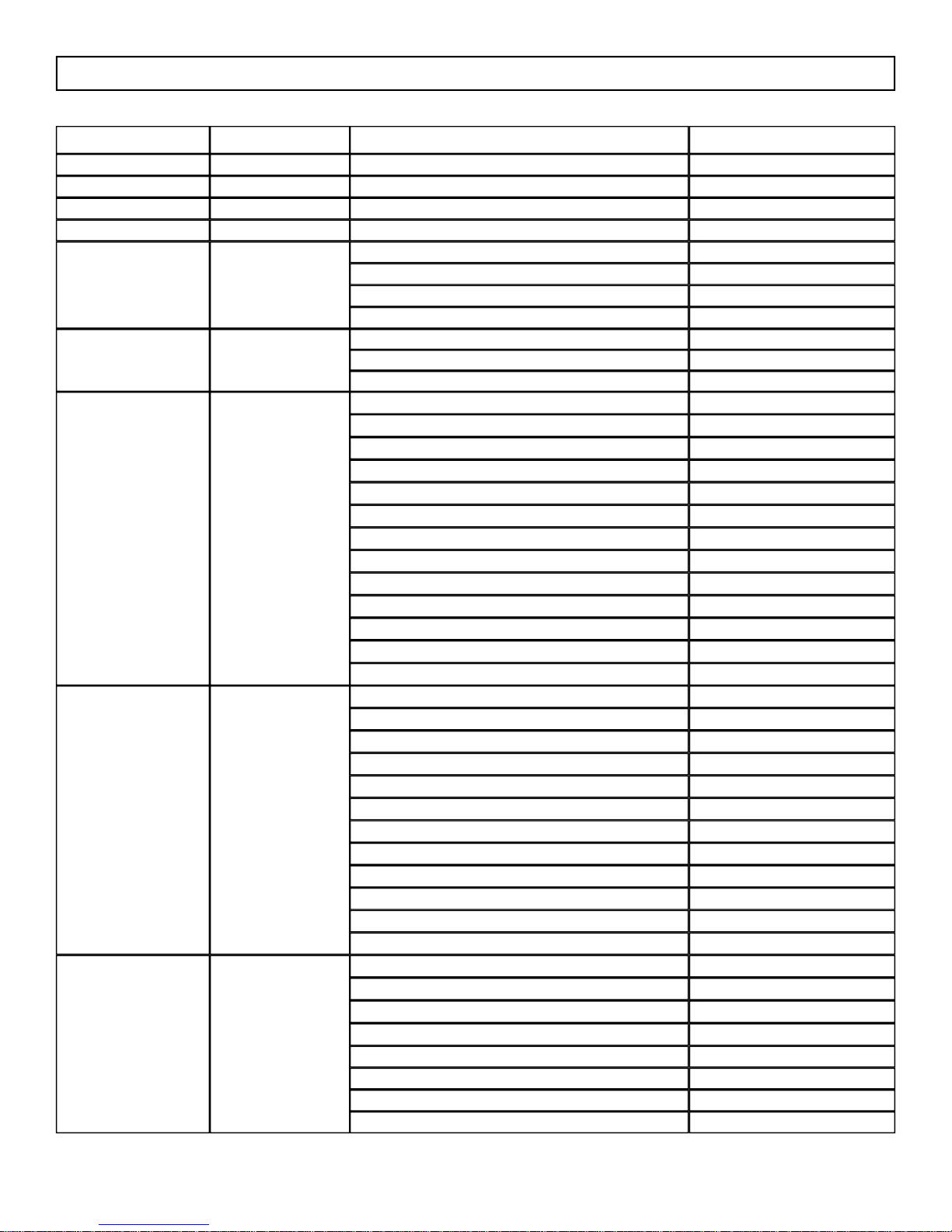
Axis 500 DMX profile-version 1.0
DMX Channel Function Description Value
1 Pan Pan course 0-255
2 Tilt Tilt course 0-255
3 Pan Fine Pan fine 0-255
4 Tilt Fine Tilt fine 0-255
5
6
7
8
9
(Bi-color beam if set
between color)
(Snap color wheel)
Speed
Control
Color 1
Color macros if channel 8 set between 128-255
Color 2
Enable macro color function on Channel 7
Prism
Max speed (tracking mode)
Max to min speed (vector mode)
Changes
Changes with pan and tilt movement
Fan speed from fast to slow
Lamp on
Lamp off (hold 3 seconds)
Open
Light blue
Red
Blue
Light Green
Yellow
Magenta
Cyan
Green
Orange
Forward rainbow effect fast to slow
Backward rainbow effect fast to slow
Open
Deep red
Deep Blue
Pink
Cyan
Magenta
Yellow
6000K filter
3200K filter
UV filter
Open
Open
Forward rotation from fast to slow
No rotation
Backward rotation from slow to fast
Prism gobo macro1 128-135
Prism gobo macro 2 136-143
Prism gobo macro 3 144-151
Prism gobo macro 4 152-159
0
1-249
250-252
253-255
0-127
128-139
230-239
0
13
26
38
51
64
77
90
102
115
128-190
194-255
0-255
0-11
12-23
24-35
36-47
48-59
60-71
72-83
84-95
96-107
108-119
120-127
128-255
0
1-63
64
65-127
8
Page 9
9
10
11
12
13
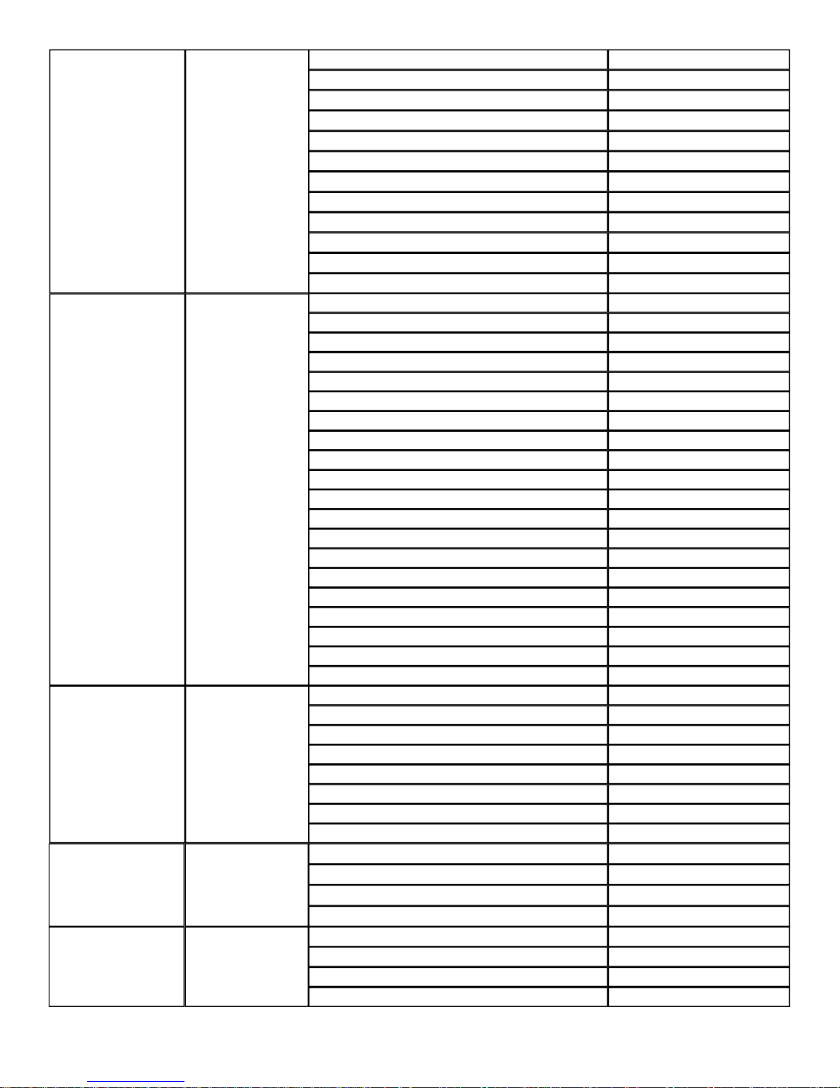
Prism Con’t
Gobo Wheel 1
Gobo Wheel 2
(Rotating/Indexing)
Rotating/ Indexing
(Gobo Wheel 2)
Iris
Prism gobo macro 5
Prism gobo macro 6
Prism gobo macro 7
Prism gobo macro 8
Prism gobo macro 9
Prism gobo macro 10
Prism gobo macro 11
Prism gobo macro 12
Prism gobo macro 13
Prism gobo macro 14
Prism gobo macro 15
Prism gobo macro 16
Open
Gobo 1Mega gear
Gobo 2 Blue halo
Gobo 3 Broken glass
Gobo 4 Rock
Gobo 5 3 Circles
Gobo 6 Every way
Gobo 7 Boomerang
Gobo 8 Bars
Gobo 9 Pebbles
Gobo 1 With variable gobo shaking
Gobo 2 With variable gobo shaking
Gobo 3 With variable gobo shaking
Gobo 4 With variable gobo shaking
Gobo 5 With variable gobo shaking
Gobo 6 With variable gobo shaking
Gobo 7 With variable gobo shaking
Gobo 8 With variable gobo shaking
Gobo 9 With variable gobo shaking
Gobo wheel rotation slow to fast
Open
Gobo 1 Metal curtain
Gobo 2 Velvet ripple
Gobo 3 Hell cloud
Gobo 4 Magenta sun
Gobo 5 Space bubbles
Gobo 6 Metal bar
Gobo wheel rotation slow to fast
160-167
168-175
176-183
184-191
192-199
200-207
208-215
216-223
224-231
232-239
240-247
248-255
0-7
8-15
16-23
24-31
32-39
40-47
48-55
56-63
64-71
72-79
80-95
96-111
112-127
128-143
144-159
160-175
176-191
192-207
208-223
224-255
0-31
32-63
64-95
96-127
128-159
160-191
192-223
224-255
Gobo Indexing 0-127
Forward gobo rotation fast to slow 128-191
No rotation 192-
Backward gobo rotation slow to fast 193-255
Open 0
Max diameter to min diameter 1-179
Closed 180—191
Pulse fast to slow 192-255
9
Page 10
14
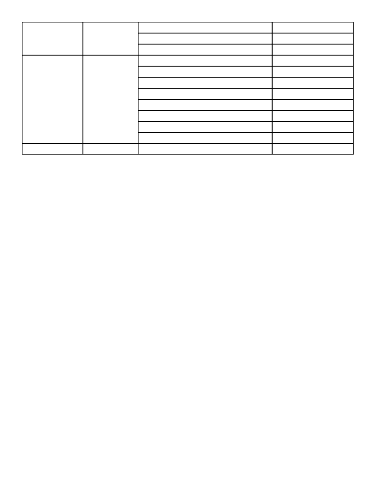
Focus / Zoom
15º Beam with focus cont far to near
18º Beam with focus cont far to near
22º Beam with focus cont far to near
0-85
86-170
171-255
15
Shutter
16 Dimmer
Shutter closed
Shutter open
Strobe slow to fast
Shutter open
Pulse effect slow to fast
Shutter open
Random strobe slow to fast
Shutter open
Dimmer from 0% to 100%
0-31
32-63
64-95
96-127
128-159
160-191
192-233
225-255
0-255
10
Page 11
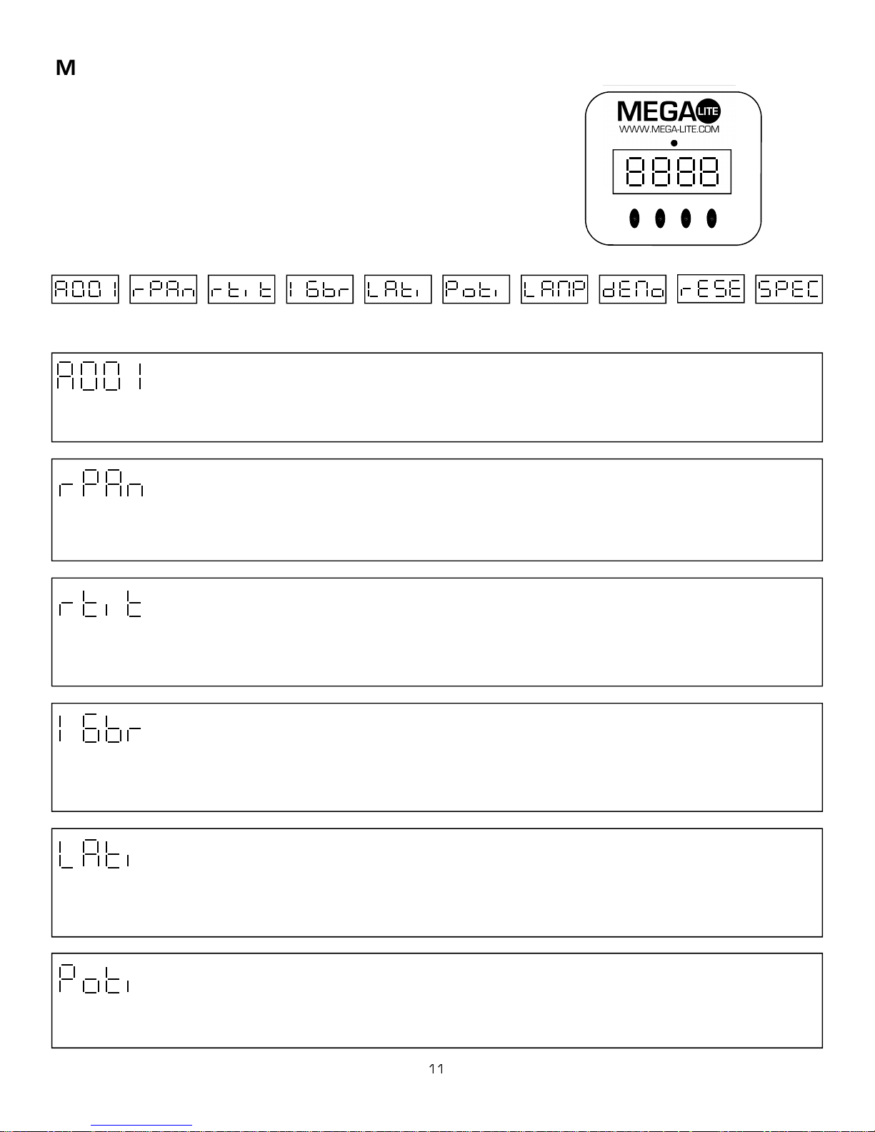
Main Control Menu
The control board on the fixture base is your interface to access and control
all the functions on the unit. Its digital display gives you a code view of the
options and functions including errors and diagnostics. The following will ex-
plain each function and its options.
MODE
DMX
ENTER
DOWN
UP
MODE
ENTER
UP
DOWN
DMX Address Reverse Pan Reverse tilt
0-512 On/Off
On / Off On / Off = Hours = Hours On / Off 2 Modes Reset 10 Functions
# DMX Channels Lamp hours
Power hours Lamp on/off Demo Advanced
Unit Reset
DMX Address
Use the up/down keys to select the required DMX channel. Press Enter to confirm or Mode to exit and return to main menu.
The display will flash if there is no DMX signal been received from the console. The Axis 500 uses 16 or 14 DMX channels
Reverse Pan
This function allows you to invert the Pan direction. Use the up/down keys to select, on to invert pan and off not to invert the
pan. Press Enter to confirm or Mode exit and return to the mail menu.
Reverse Tilt
This function allows you to invert the Tilt direction. Use the up/down keys to select, on to invert tilt and off not to invert the tilt.
Press Enter to confirm or Mode exit and return to the mail menu.
#DMX Channels
This function allows you to chose from fine pan and tilt 16 bit resolution or 8 bit pan and tilt movement. It also determines if the
unit will operate on 16 or 14 channels of DMX. Use the up/down keys to select, on to select 16 bit resolution and off to select
8 bit resolution. Press Enter to confirm or Mode exit and return to the mail menu.
Lamp Hours
This option allows you to read the number of hours the lamp has been powered on. Press Enter to confirm or Mode exit and
return to the mail menu. You should reset the lamp hour meter every time you replace the lamp. To reset the counter hold the
up and down and press enter.
Power Hours
This option allows you to read the number of hours the unit has been powered on. Press Enter to confirm or Mode exit and re-
turn to the mail menu.
Page 12
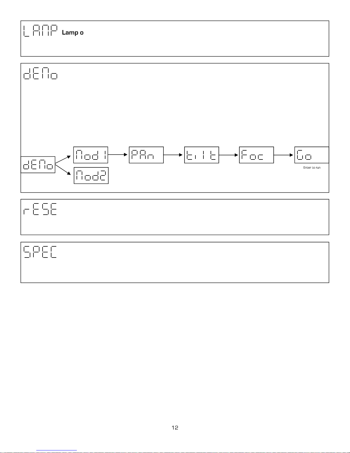
Lamp on/off
This function allows you to turn the lamp on or off. Use the up/down keys to select on to turn the lamp on and off to turn the
lamp off. Press Enter to confirm or Mode to exit and return to main menu.
Demo sequence
This function allows you to run two special demo test sequences without an external controller. Use the up / down keys to select
between (mod1) and (mod2). Mod 1 allows you to position the pan, tilt and focus. Then, you can conduct a test or demo of a
units functions with out movement. Mod 2 will run through all the functions automatically with pan and tilt. If you select mod1,
you will be able to adjust the Pan Tilt and Focus. After each function you can go up / down to desired setting press Enter to con-
firm and Mode to go back to the last option. After your personal setting have been set you can go to the (Go) function to run se-
quences. If you select demo mod2, press Enter to confirm or Mode to exit and return to main menu. Mod 2 will repeat until
mod2 is deactivated by pressing Mode.
Enter to run sequence
0-255 Up/Down Enter
0-255 Up/Down Enter
0-255 Up/Down Enter
Unit Reset
This option enables the Axis 500 to index all functions and return to their standard positions. Press Enter to confirm or Mode to
exit and return to main menu.
Advance settings
This function opens up another group of advance maintenance and important settings. It is recommended that advance setting
be used by an authorized user only.
12
Page 13
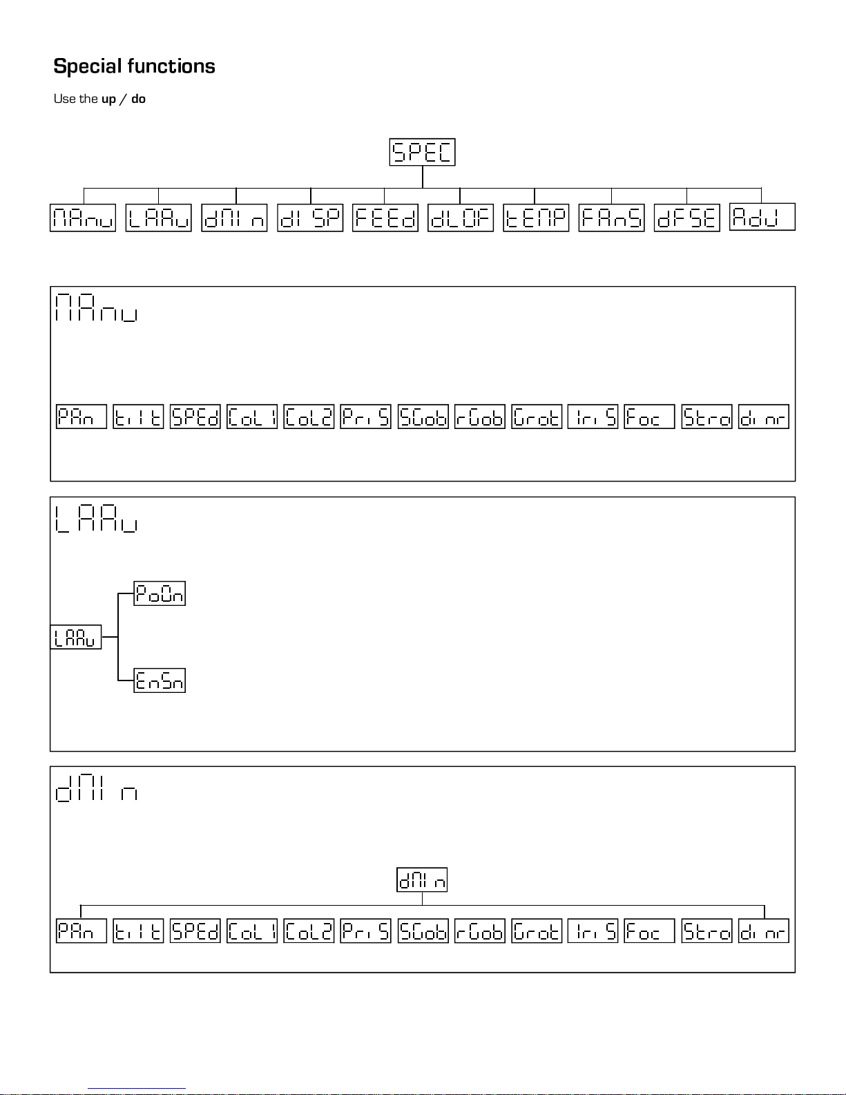
Use the up / down keys to browse through the special funcions and select one by pressing Enter.
Manual control
Lamp control
DMX values
Display options
Pan/Tilt feedback Lamp DMX Control Temperature
Fan speed
Default settings
Adjusting default
Manuel control
This function allows you to manually control each channel function. Use the up/down keys to select desired function and press
Enter to adjust the effect, or Mode to cancel and return to the main menu.
Pan1
/
Pan3
Til1
/
Til3
Spd1
/
Spd5
Co10
/
Co19
Colr
Co20
/
Co29
Hole
Pr0
Pr6
/
Sg0
/
Sg19
Rgo0
/
Rgo7
Gro1
/
Gro9
Iri1
Iri7
/
Foc1
/
Foc9
Open
Str1
Str9
/
Open
Din1
/
Din4
Clos
Lamp control
This function allows you to turn the lamp on after switching the fixture on and switch on/off the lamp light sensor.
Lamp on after switching the fixture on. This function allows you to turn the lamp on automatically
after switching on the fixture. Use the up/down key to set On or Off When On is selected the lamp
turns on after power was been struck, When Off is selected the lamp to stay off after power has been
turned on. Press Enter to confirm or Mode to cancel and return to the menu.
Switch on/off lamp light sensor. Use the up/down keys to select on or off if you wish to switch the
lamp sensor on or off. Press Enter to confirm or Mode to cancel and return to the menu.
Caution:
Other electrical part can be damaged if lamp sensor is left off for a long period of time.
DMX values
Readout of DMX values of each channel received by the fixture. Use the up/down key to select desired channel and press Enter
to read its individual channel value or Mode to cancel and return to menu.
0-255 0-255
0-255
0-255
0-255
0-255
0-255
13
0-255 0-255
0-255 0-255 0-255 0-255
Page 14
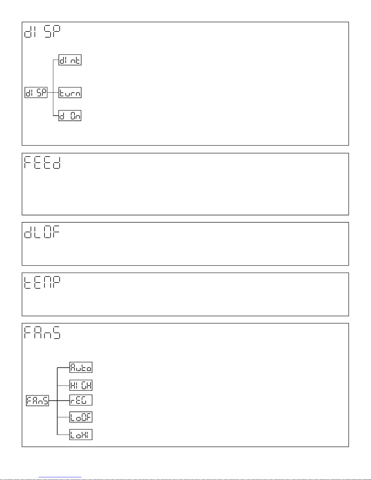
Display options
This function allows you to set display intensity, reverse the display and turn the display on of off.
Display intensity: with this function you can adjust the display-intensity from 20% to 100%. Use
up/down Keys to select the level of display intensity and press Enter to confirm or Mode to cancel and
return to menu.
Reverse display: with this function you can rotate the display 180º. Use the up/down key to select rota-
tion of display and press enter to confirm or mode to cancel and return to main menu.
Display on/off: this function allows you to keep the display on or to turn off the display automatically 2
minutes after last pressing any key. Use the up/down keys to select on if you wish to keep the display on
or off if you wish to turn the display off after 2 minutes. Press Enter to confirm or Mode to cancel and
return to the main menu
Pan/Tilt feedback
This function allows you to return the moving head to the required position after changing the position by external force. Use the
up/down keys select on if you wish to enable this function or off if you wish not to return the moving head to the required position
and press Enter to confirm or Mode to cancel and return to main menu.
Caution:
the moving head might not be synchronized with the DMX signal. You have to make a reset in order to synchronize the moving
head with the DMX signal.
If feedback was switched off, the pan/tilt position is changed by external force and the feedback is switched on again ,
Lamp DMX Control
This function allows you to switch on and off the lamp by DMX. Use the up/down keys to select On if you want to switch off the
lamp by DMX or Off if you don’t want to switch off the lamp by DMX. Press Enter to confirm or Mode to cancel and return to
main menu.
Temperature
Inside temperature readouts of the fixture in Celsius. If inside temperature below 80ºC are not critical but not recommended for
long periods of time. 80ºC and more will cause the lamp to switch off. Please note that the outside temperature should not ex-
ceed 45ºC
Fan speed
By using this function you can choose between 5 types of fan speed. Browse through this menu by using the up/down keys.
Press Enter to confirm and Mode to return back to the main menu.
Automatically: raises its speed and slows down to control the inside temperature of the light. This
function can’t be controlled by DMX
High Speed: The cooling fans work on max speed
Regular: The cooling fans automatically raises its speed and slows down to control the inside tem-
perature of the light.
Low/High speed: The fan keeps the adjusted low speed until the maximum inside temperature is
exceeded, then the fan automatically switches from low to high speed
Low speed lamp off: The fan keeps the adjusted low speed until the temperature exceeds the maxi-
mum inside temperature, then the lamp automatically switches off.
14
Page 15
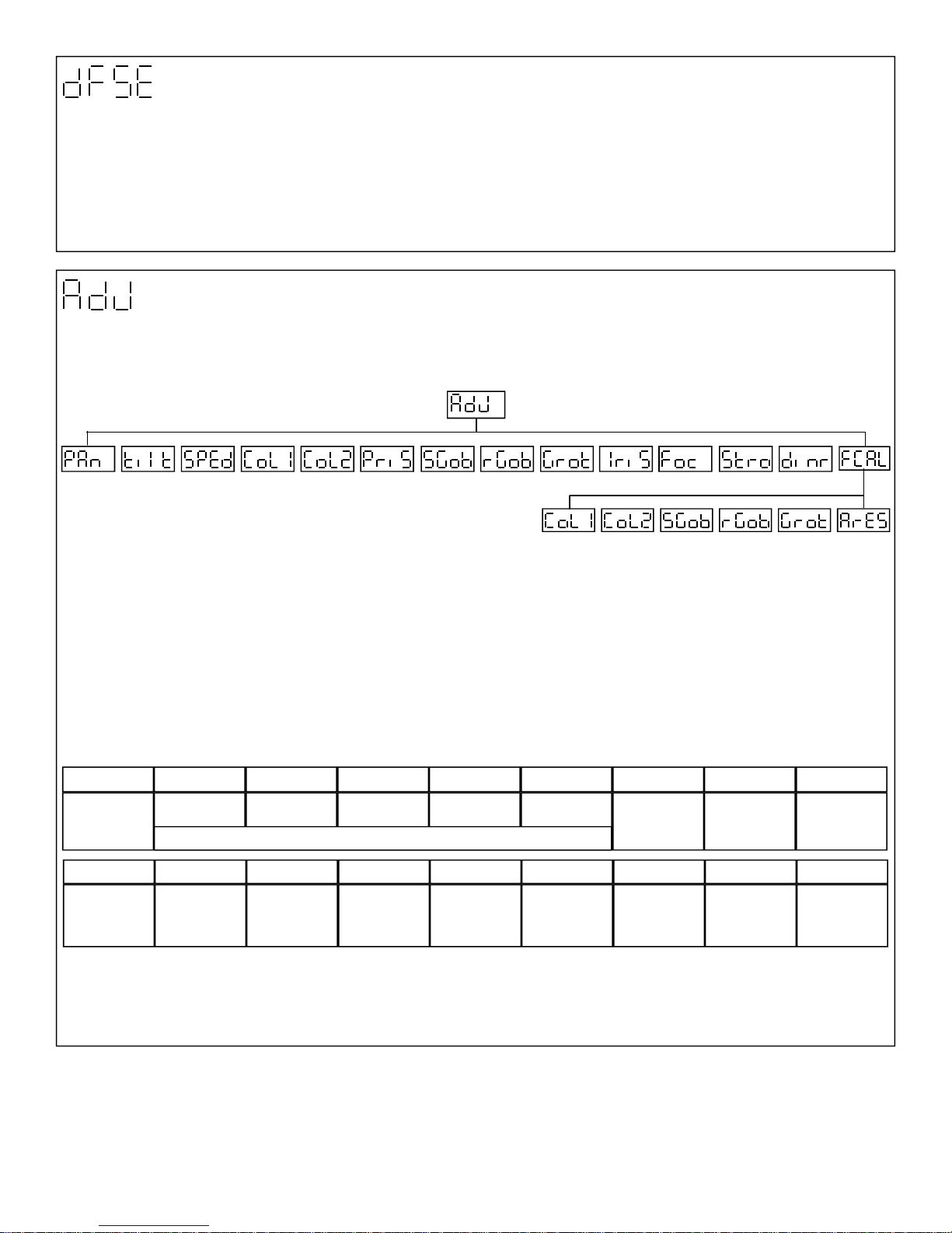
Default settings
Press Enter to reset all fixture personalities to the default values. Default setting are
Reverse Pan: Off
Reverse Tilt: Off
16 bit resolution: On
Lamp on automatically: Off
Lamp sensor: On
Display options: 100
Display turn: Turn
Feed back: On
Lamp Control: On
Fan Speed: Auto
Display options: On
Adjusting the default positions of color, gobo and effect
With this function you can calibrate and adjust the color, gobo and effect wheel to their standard position. Use the up/down keys
to browse through the adjusting menu by which you can adjust the fixture to the required position (0-250)before the function
calibration.
0-255 0-255
0-255
0-255
0-255
0-255
0-255
0-255 0-255
1. Calibration via control board: Press Enter and the up/down keys in order to display the following message: Col1, Col2,
PriS, SGob, rGob, Grot for very smooth function calibration. Select the function that needs calibration by pressing Enter and use
the up/down keys in order to adjust the right value from 0 to 255. Then press Enter to confirm or Mode to cancel and return
to the main menu. This can be repeated for each calibration required. When the calibration is finished it is necessary to use the
ArES function in order to write the calibration values to the memory (eeprom) and to make reset in order to check the newly
adjusted positions. When the reset of the fixture is completed the display will read FCAL message. Press Enter to repeat the
calibration or Mode to return to the ADJ menu.
0-255 0-255 0-255 0-255
2. Calibration via external controller: Press Enter and the up/down keys in order to display the following message: Colo,
EFEC, rGob, Grot for very smooth function calibration. Select the function that needs calibration by pressing Enter. Now you can
calibrate the color, gobo and effect wheel via your controller. The DMX calibration protocol is described in the table below.
DMX Channel 1 2 3 4 5 6 7 8
Function
DMX Channel 9 10 11 12 13 14 15 16
Function
Col.1 Col. 2 SGOB RGOB GROT - Colors 1
Standard
Protocol
STROBE
Standard
Protocol
PRISM
-
Standard
Protocol
Smooth micro step movement
STATIC GOBO
-
Standard
Protocol
ROTATIN GOBOS
-
Standard
Protocol
GOBO ROTATION
-
Standard
Protocol
IRIS
-
Standard
Protocol
FOCUS
-
Standard
Protocol
-
-
Colors 2
-
Standard
Protocol
DIMMER
-
Standard
Protocol
When the calibration is finished it is necessary to use the ArES function in order to write the calibration values to the memory
(eeprom) and to make reset in order to check the newly adjusted positions. When the reset of the fixture is completed the dis-
play will read FCAL message. Press Enter to repeat the calibration or Mode to return to the ADJ menu.
15
Page 16
Error Messages
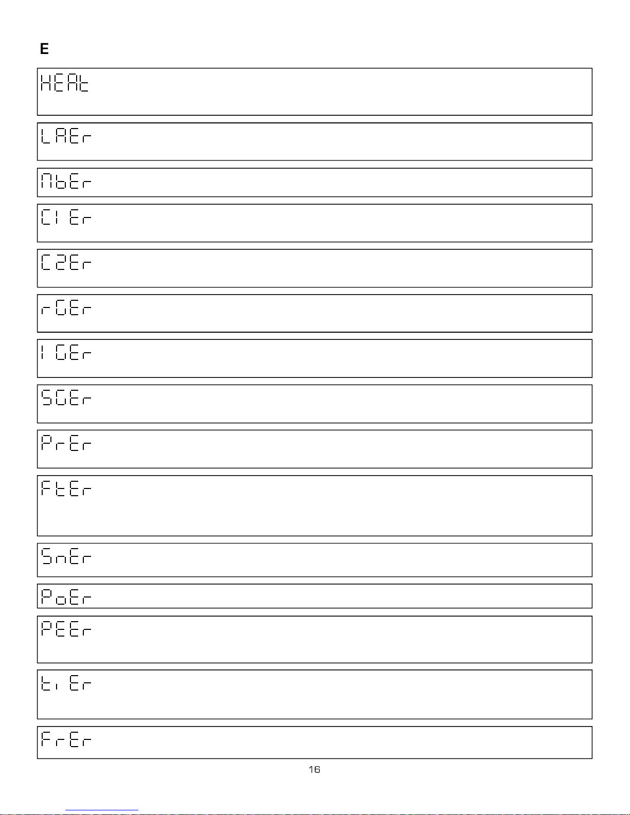
Heat error: This message appears if you try to switch the lamp on within 5 minutes after having turned off the
lamp. The message will also appear if the lamp doesn’t ignite within 28 seconds. The unit will automatically try to
ignite the lamp again when 5 minutes have passed.
EnSN) this function is disabled. If problem persist contact your dealer or service center.
Lamp error: The unit attempted to strike the lamp more than seven times without success, or the lamp is dam-
aged, missing or the unit has overheated several times. This may occur in ambient temperatures of 45ºC and
above. Or it could be failure in the igniter or ballast.
Mother board error: This message indicates that the main PCB is not communicating correctly with the control
board.
Color wheel 1 error: This indicates a problem with the color wheel 1. This could be a defective magnetic indexing
circuit sensor or a bad stepper motor.
from color wheel. Confirm stepper motor is rotating. Have a dealer or authorized service center check the unit.
Color wheel 2 error: This indicates a problem with the color wheel 2. This could be a defective magnetic indexing
circuit sensor or a bad stepper motor.
Rotating gobo wheel error: The rotating gobo wheel is not located in the default position after the reset. This
could be a defective magnetic indexing circuit sensor or a bad stepper motor or a defective driver circuit in the
main PCB.
Rotating gobo indexing error: The rotating gobo is not located in the default position after the reset. This could
be a defective magnetic indexing circuit sensor or a bad stepper motor or a defective driver circuit in the main
PCB.
Have a dealer or authorized service center check the unit
If problem continues have a dealer or authorized service center check the unit.
If problem continues have a dealer or authorized service center check the unit.
Check or replace lamp If lamp sensor is switched off (function
Check or replace lamp. If problem persist contact your dealer
Check the connection from PCB to sensor. Confirm magnet is not missing
Check the connection from PCB to sensor. Confirm magnet is not missing
Static gobo wheel error: The static gobo is not located in the default position after the reset. This could be a de-
fective magnetic indexing circuit sensor or a bad stepper motor or a defective driver circuit in the main PCB.
If
problem continues have a dealer or authorized service center check the unit.
Prism wheel error: The prism wheel is not located in the default position after the reset. This could be a defective
magnetic indexing circuit sensor or a bad stepper motor or a defective driver circuit in the main PCB.
If problem
continues have a dealer or authorized service center check the unit.
Fixture temperature error: This error informs you that the fixture has overheated (occurred if the ambient tem-
perature is 45ºC or more) and the relay has switched off the lamp. This message will appear on the display until
the temperature reaches a suitable level, then the display will show a HEAt message meaning the lamp is to hot.
You will need to wait until the lamp has cooled to restart the unit.
Check that fans are working and heat sensors
are operational. If problems continue have a dealer or authorized service center check the unit.
Lamp sensor error: This message appears if the lamp sensor has failed.
If problem occurs have a dealer or au-
thorized service center check the unit.
Power error: This message will appear if the fixture was shortly disconnected from the mains.
Pan movement error: The yoke is not located in the default position after the reset. This could be a defective mag-
netic indexing circuit sensor or a bad stepper motor or a defective driver circuit in the main PCB.
Check to make
sure that there is nothing obstructing the path, if problem continues have a dealer or authorized service center
check the unit.
Tilt movement error: The head is not located in the default position after the reset. This could be a defective mag-
netic indexing circuit sensor or a bad stepper motor or a defective driver circuit in the main PCB.
Check to make
sure that there is nothing obstructing the path, if problem continues have a dealer or authorized service center
check the unit.
Frequency error: This message will appear if the frequency of the main power is not a standard 50 or 60Hz.
Page 17
Installation Maintenance: The operator has to make sure that the unit is operating safely and has the installations and electron-
ics checked by an expert every 2 years.
The following points have to be considered during the inspection:
1) All screws used for installing the device or part of the device have to be tightly connected and must not be corroded.
2) There must not be any deformations on the housing, fixation and installation spots(ceiling, suspension, trussing).
3) Mechanically moved parts like axles, eyes and other must not show any traces of wearing and must not rotate with unbal-
ances.
4) The electronic power supply cables must not show any damages, material fatigue(e.g. porous cables) or sediments. Further
instructions depending on the installation spot and usage have to be adhered by a skilled installer and any safety problems
have to be removed.
Disconnect from mains before starting maintenance operation!
Caution Danger to life!
We recommend a frequent cleaning of the device. Please use a moist, lint free cloth. Never use alcohol or sol-
vents!
1) The objective lens will require periodic cleaning on usage and environment. Environment with foggers will require more peri-
odic cleaning as fog fluid tends to build up residues, reducing the light output.
2) The cooling-fans should be cleaned monthly. DO NOT blow high pressure air into fans as incorrect rotation can damage the
fans operation.
3) The gobos, dichroic color filters and internal lenses may be cleaned with soft brush using soapy water.
4) The interior of the fixture should be cleaned using a vacuum.
5) We recommend proper lubrication of the gobo wheel. The quantity of the oil must not be excessive in order to avoid oil run
Note: There is no serviceable parts inside the device except for the lamp anf the fuse. Maintenance and service operations are
to be carried out by authorized dealers.
Replacing the fuse: Only replace the fuse with the same type and rating.
Replacing the power cable: If the power cable of this device becomes damaged, it has to be replaced by authorized dealers only
In order to avoid hazards.
Should you have further questions , please contact your dealer.
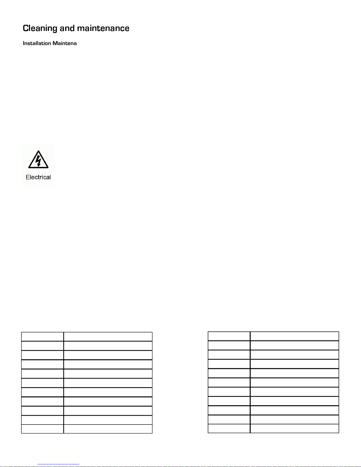
Parts List
P-1010case Dual Axis 500 Case
P-1010PCB Main PCB Card
P-1010DC-AB Driver Card
P-1010DC-DC Driver Card
P-1010DIS Display Card
P-1010FAN Fan 3X3
P-1010FAN-S Lamp Fan 1.5X1.5
P-1010IG Igniter
P-1010PRISM Prism
P-1010R-SET Qui ck Release Mount Set
P-1010RF Reflector
LMSR575/2 Phillips MSR 575/2
LMSD575 Phillips MSD 575
LNSK575 NSK 575
P-1010IRF IR Filter
P-1010FLS Full Lens Set
P-1010FGS Full Gobo Set
P-1010FPBS Full Plastic Body Set
P-1010CWM Color Wheel Motor
P-1010FCW 1Color Wheel
P-1010RPST Power Supply Transformer
P-1010CSPCB Color Sensor PCB
17
Page 18

Ph 210-684-2600 Fax 210-855-6279
www.mega-lite.com / info@mega-lite.com
Mega-Lite
5718 Kenwick St
San Antonio, TX 78238
 Loading...