

Page 1

SPECIALTY HAULAGE SOLUTIONS FOR CONSTRUCTION AND MINING
OPERATORS MANUAL
MTT-OPS-1
GENUINE MEGA.
MEGA CORP.®
700 Osuna Rd. N.E. • Albuquerque, NM 87113 • 1-800-345-8889 • 505-345-2661 • Fax 505-345-6190
www.megacorpinc.com
® MEGA Corp., Inc. All Rights Reserved
Page 2

MTT-OPS-1
13 Nov 2013
TABLE OF CONTENTS
Page
Section 1 Definitions and Abbreviations . . . . . . . . . . . . . . . . . . . . . . . . . . . . . . . . . . . . . . . . . . . . . . . . . 1-1
Section 2 System Description. . . . . . . . . . . . . . . . . . . . . . . . . . . . . . . . . . . . . . . . . . . . . . . . . . . . . . . . . . . .2-1
Section 3 Limitations. . . . . . . . . . . . . . . . . . . . . . . . . . . . . . . . . . . . . . . . . . . . . . . . . . . . . . . . . . . . . . . . . . . . 3-1
Section 4 Normal Operations . . . . . . . . . . . . . . . . . . . . . . . . . . . . . . . . . . . . . . . . . . . . . . . . . . . . . . . . . . . .4-1
Section 5 Performance . . . . . . . . . . . . . . . . . . . . . . . . . . . . . . . . . . . . . . . . . . . . . . . . . . . . . . . . . . . . . . . . . . 5-1
Section 6 Employment . . . . . . . . . . . . . . . . . . . . . . . . . . . . . . . . . . . . . . . . . . . . . . . . . . . . . . . . . . . . . . . . . .6-1
Section 7 MTT Operator’s Checklist . . . . . . . . . . . . . . . . . . . . . . . . . . . . . . . . . . . . . . . . . . . . . . . . . . . . . .7-1
A
Page 3

MTT-OPS-1
13 Nov 2013
TABLE OF CONTENTS
B (Blank)
Page 4

SECTION 1
Definitions and Abbreviations
Contents
MTT-OPS-1
13 Nov 2013
Warning, Cautions & Notes ........................................1-1
Shall, Will, Should and May ........................................1-1
Safety Messages ............................................................1-2
MANUAL USAGE
This technical manual only contains information
required to safely operate the MTT. See the
appropriate Maintenance and Operators Safety
Manual for specific vehicle system information and
maintenance procedures. The exact location of the
hazards and description of the hazards are reviewed
in this section. All personnel working on or operating
the MTT must become familiarized with all the safety
messages.
If your system is not covered in this manual please
contact MEGA Corp. Product Support Group at:
US toll free: 1-800-345-8889
Direct: 1-505-345-2661 or visit our website at
www.megacorpinc.com
information.
See the proper manufacture specific Operation &
Maintenance, Safety Manuals and Service Manuals
for detailed chassis system information and chassis
specific maintenance procedures.
for more detailed contact
Abbreviations ................................................................. 1-5
MTT Overview ................................................................1-6
WARNING, CAUTION AND NOTES
The following definitions are found throughout the
manual and apply as follows:
Operating procedures and techniques, which could
result in personal injury and/or loss of life if not
carefully followed.
Operating procedures and techniques, which could
result in damage to equipment if not carefully
followed.
Operating procedures and techniques that are
considered essential to emphasize.
USE OF SHALL, WILL, SHOULD AND MAY
Due to the nature of these processes, ensure that all
safety information, warnings and instructions are
read and understood before any operation or any
maintenance procedures are performed. Some
procedures take place with heavy components and
at moderate heights, ensure proper safety
procedures are maintained when performing these
actions. Failure to use and maintain proper safety
equipment and procedures will cause injury, death or
damage to equipment.
Shall and Will – Used when application of a
procedure is mandatory.
Should – Used when application of a procedure is
recommended.
May - Used to indicate an acceptable or suggested
means of accomplishment.
1-1
Page 5
MTT-OPS-1
13 Nov 2013
SECTION 1
Definitions and Abbreviations
SAFETY MESSAGES
There are several specific safety messages on this
machine. The exact location of the hazards and
description of the hazards are reviewed in this
section. All personnel working on or operating the
machine must become familiarized with all the safety
messages.
Make sure that all of the safety messages are legible.
Clean the safety messages or replace the safety
messages in you cannot read the words. Replace the
illustrations if the illustrations are not legible. When
you clean the safety messages, use a cloth, water and
soap. Do not use solvent, gasoline or other harsh
chemicals to clean the safety messages. Solvents,
gasoline or harsh chemicals could loosen the
adhesive that secures the safety messages. Loose
adhesive will allow the safety messages to detach.
Replace any safety message that is damaged or
missing. If a safety message is attached to a part that
is replaced, install a new safety message on the
replacement part.
DO NOT OPERATE (2)
This safety label is located on the outside of the front
and rear control boxes (if equipped).
Do not open this control box unless you read and
understand the instructions and warnings in the
Operator and Maintenance Manual. Failure to
follow instructions or heed the warnings could
result in serious injury or death.
TOXIC G AS H AZAR D (1)
This safety label is located on the side of the tank and
at all water fill entrances.
Cutting or welding operation on the inside of the
tank can cause the accumulation of toxic gases.
Read and understand instructions and warnings
in the Maintenance Manual. Failure to provide
proper ventilation or breathing apparatus while
conducting these operations may result in serious
injury or death.
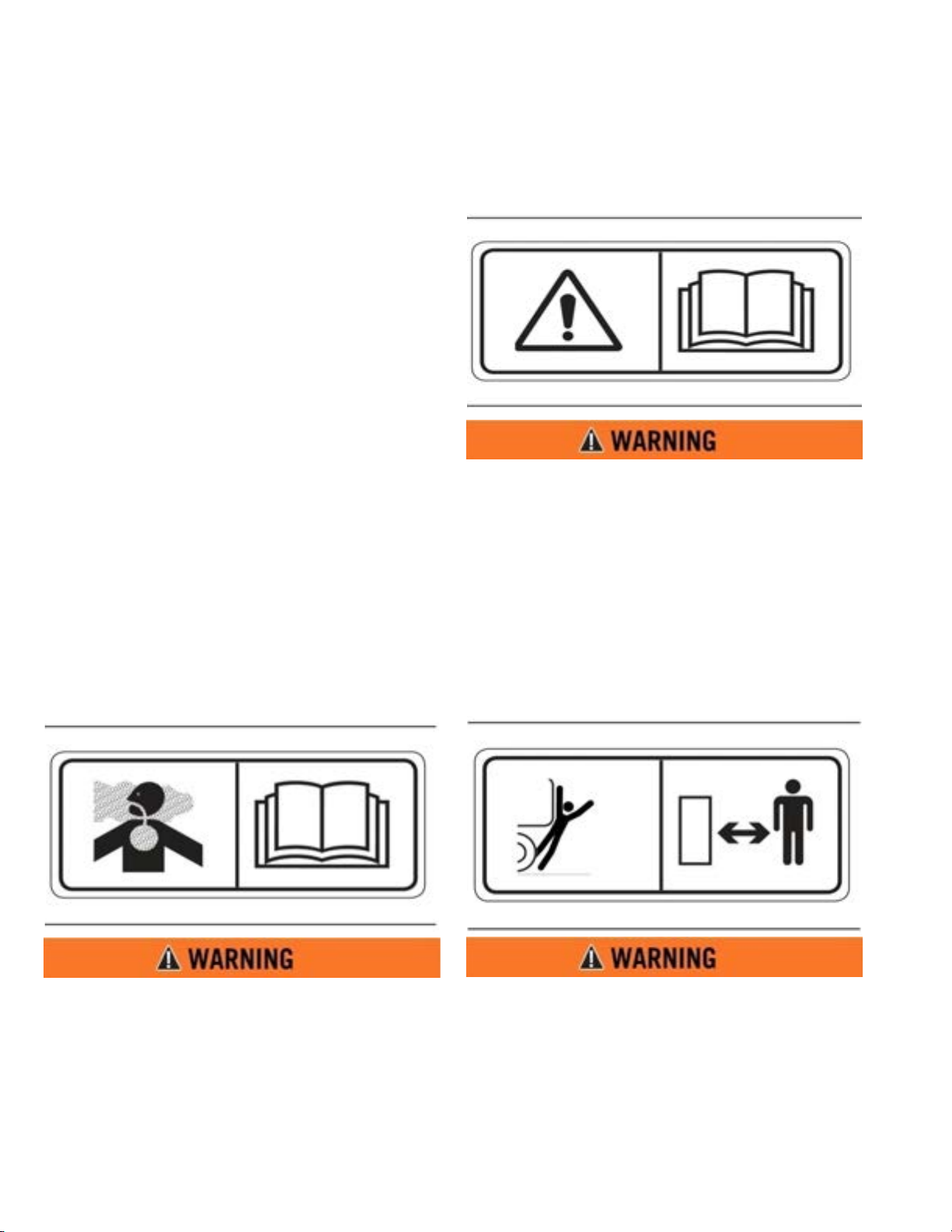
BACKING RUNOVER HAZARD (3)
This safety label is located on the rear of the tank and
inside the cab.
The vehicle is equipped with a back-up alarm.
Alarm must sound when operating this vehicle in
reverse. Failure to maintain a clear view in the
direction of travel could result in serious injury or
death.
1-2
Page 6

SECTION 1
Definitions and Abbreviations
MTT-OPS-1
13 Nov 2013
FREEZING (4)
This safety label is located on the side of the tank, at
the sump drain, and on the pump.
Drain tank, fill pipe and valve in freezing weather.
Refer to the Operator and Maintenance Manual
for the procedure to follow.
DO NOT HOIST WHILE IN MOTION (6)
This safety label is located inside the cab.
Do not engage hoist cylinders while vehicle is in
motion. Before engaging hoist STOP the vehicle.
Do not engage hoisting cylinders unless you read
and understand the instructions and warnings in
the Operator or Maintenance Manual. Failure to
follow instructions or heed the warnings will
result in injury or death.
NON-POTABLE (5)
This safety label is located on the side of the tank and
sump drain.
Water held within tank is not potable. Do not use
tank for transport of water intended for human or
animal consumption or serious injury or death
may result.
FALL HAZARD (7)
This safety label is located at the top of the front and
rear of the tank.
Do not walk on the top of tank without fall arrest
PPE. Serious injury or death could occur from a
fall.
1-3
Page 7
MTT-OPS-1
13 Nov 2013
SECTION 1
Definitions and Abbreviations
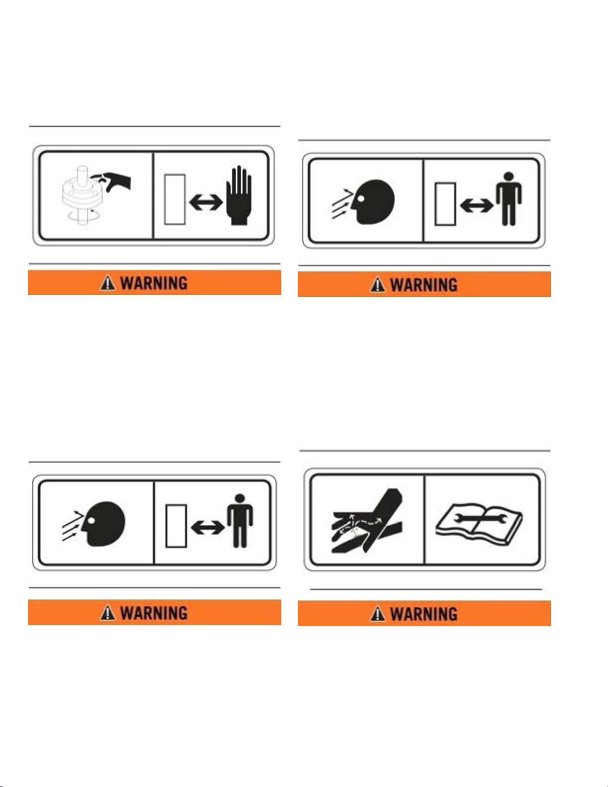
ROTATING SHAFT (8)
This safety label is located on the pump.
Do not place your hand or tools within pump bell
while pump is rotating and/or pressure held
within the motor supply hose. Refer to the
Operator and Maintenance Manual for the
procedures to operate and maintain the pump.
Failure to follow proper procedures could result in
serious injury.
HIGH PRESSURE WATER CANNON (10)
This safety label is located on top of the cab control
box.
Do not operate the water cannon until all
personnel are a safe distance away from the
vehicle.
HIGH PRESSURE SPRAY HEADS (9)
This safety label is located on the spray bar.
Do not operate spray heads until all personnel are
a safe distance away from the vehicle.
HIGH PRESSURE MOTOR (11)
This safety label is located on the hydraulic motor.
Hydraulic motor and supply lines contain oil
under high pressure. Improper removal and
repair procedures could cause severe injury. To
remove or repair, instructions in the Maintenance
Manual must be followed.
1-4
Page 8
SECTION 1
Definitions and Abbreviations
MTT-OPS-1
13 Nov 2013
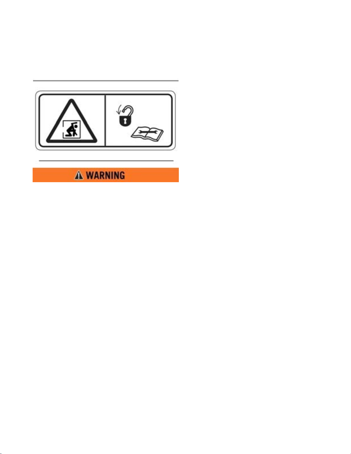
CONFINED SPACE (12)
This safety label is located near the water tank access
and fill ports.
Do not enter confined spaces without following
established site specific procedures. Failure to
follow proper safety procedures will result in
serious injury or death.
ABBREVIATIONS
BFV – Butterfly Valve
cc – Cubic Centimeters
CCW – Counter Clockwise
CW - Clockwise
fl. oz. – Fluid Ounce
FT - Feet
FPM – Feet Per Minute
GPM – Gallons Per Minute
IN/SQ FT – Inches per Square Feet
KM-H – Kilometers Per Hour
Kg – kilograms
Kpa - Kilopascals
l – liters
lpm – Liters per minute
LT – Left as viewed from the operators’ position
facing forward
m - meters
MPH – Miles Per Hour
MTT – Mega Truck Tank
Nm – Newton meters of torque
psi - pounds per square inch
RPM – Revolutions Per Minute
RT – Right as viewed from the operator’s position
facing forward
SQ FT – Square Feet
VDC – Volts, Direct Current
1-5
Page 9

MTT-OPS-1
1
2
3
5
6
7
WATER PUMP & HYDRAULIC MOTOR
HOSE REEL
CAB CONTROL
SPRAY HEADS
HAND RAIL & WALKWAY
WATER CAN NON
HYDRAULIC SOLENOID BOX
44
1
5
2
3
6
7
4
13 Nov 2013
SECTION 1
Definitions and Abbreviations
MTT OVERVIEW
1-6
Page 10
SECTION 2
System Description
Contents
MTT-OPS-1
13 Nov 2013
Water Tank (MTT) ..........................................................2-1
M-4 Water Pump ............................................................2-1
Hydraulic Drive Motor .................................................2-2
Cab Controls (Analog) .................................................2-4
Cab Controls (Digital) ..................................................2-5
Ground Speed Sensing (GPS) Control ..................2-9
Water Cannon System .................................................2-11
WATER TANK (MTT)
The MEGA steel water tank consists of a water tunnel,
primary floor, vertical baffles, 13 Nov 2013bulkheads,
outer skins, internal piping and external piping. The
tank design is patented and known as the Magnum
Anti-surge Stabilization System (MASS)
The tank structure is built around and on top of the
tunnel super structure. The tunnel provides support
to the floor plate, pivot structure, baffles and
mounting for the water pump. The floor plates carries
loads while the baffles and bulkheads add to tank
strength and dampen water surges. External and
internal piping is also used to carry water from the
water pump to spray heads, water cannon, spray bar,
hose reel, dump bar and tank drain.
Spray System .................................................................. 2-12
Dump Bar ......................................................................... 2-13
Hose Reel .........................................................................2-14
Tank Drain ........................................................................ 2-14
Fire Suppression System ............................................2-14
Water Circulation System ........................................... 2-15
Suction Loading ............................................................ 2-15
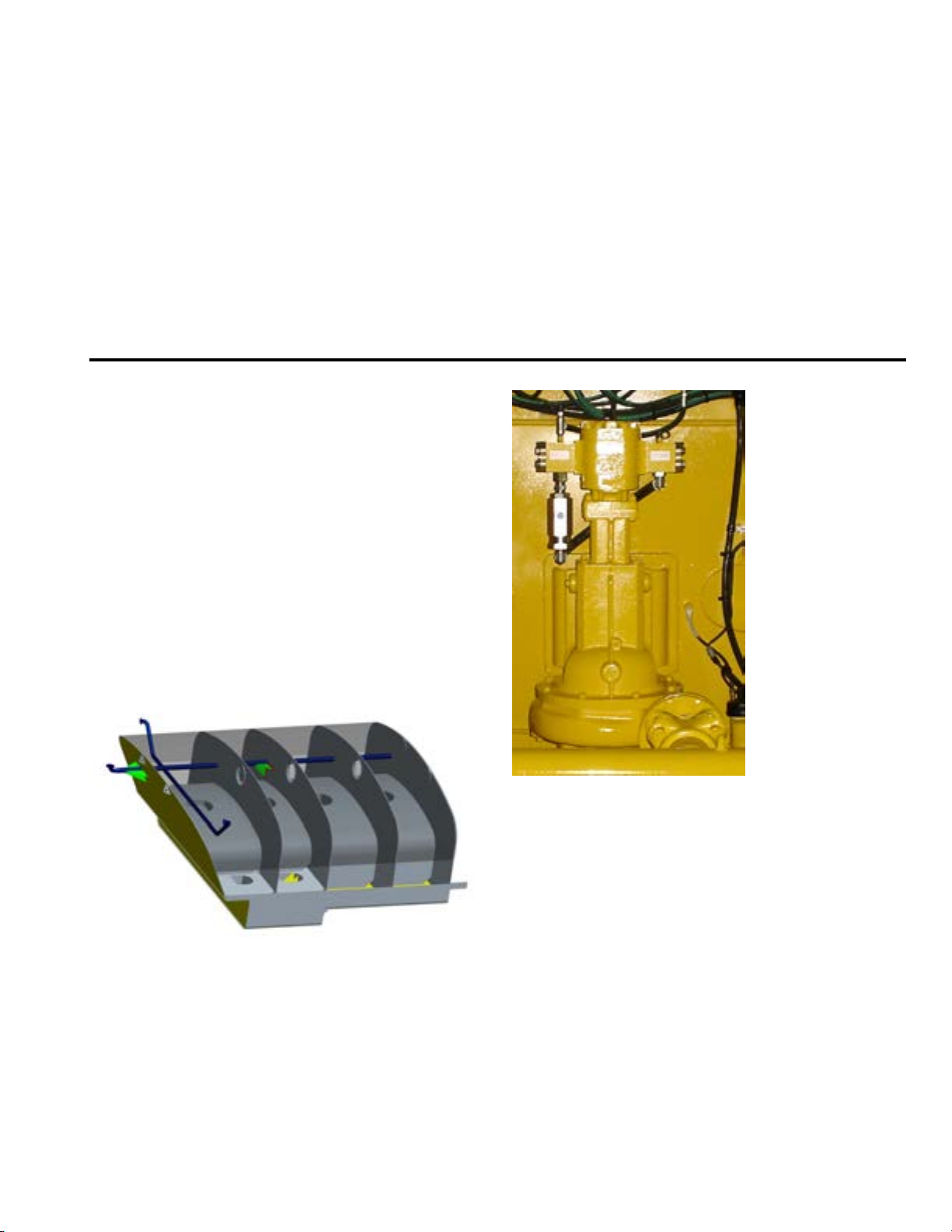
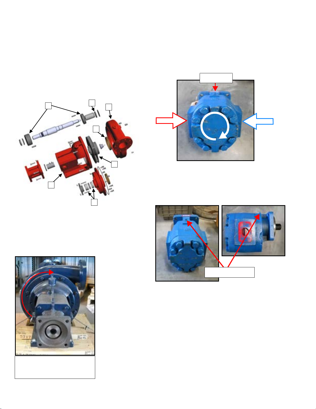
M-4 WATER PUMP
M-4 Water Pump major components and their
functions are:
1. Bracket – Main frame of the pump that allows a
pump to be bolted to the tanker and provides the
means to direct mount the hydraulic drive motor.
2. Volute Case – A “snail shell” shaped case that
encloses the impeller. It is narrow at the center
and enlarges from there to the discharge area.
3. Wear Ring – Acts as a bearing surface between
the impeller and volute case. Constructed of
bronze material.
4. Impeller – Rotating wheel attached to the shaft
that accelerates the speed of the water producing
water flow and pressure.
5. Shaft Seal – Confines grease to the inner and
outer bearing area while keeping foreign material
from entering the bearing area and seals water
inside the volute case.
2-1
Page 11
MTT-OPS-1
6
1
7
3
4
5
2
SHAFT
ROTATION
CASE DRAIN
RETURN
PRESSURE
CASE DRAIN PORT
13 Nov 2013
SECTION 2
System Description
6. Rope Seal – Provides a seal around the rotating
pump shaft at the volute case. Constructed of a
graphite rope material that is designed to drip
water and allow shaft lubrication.
7. Upper/Lower Bearings - Provide roller surface
for the pump shaft.
The hydraulic drive motor may be installed in 4
different orientations depending on the water pump
location or application.
HYDRAULIC DRIVE MOTOR PORT IDENTIFICATION
The hydraulic drive motor requires hydraulic flow
from a valve to the motor pressure port, return oil
flow to the hydraulic reservoir and a free to tank case
drain.
HYDRAULIC DRIVE MOTOR
M-4 PUMP DRIVE MOTOR AND CROSS-OVER
ASSEMBLY
The M-4 pump rotates clockwise as viewed from the
drive end of the assembly:
Clockwise rotation as viewed
from the drive end of the water
pump assembly.
2-2
Page 12
SECTION 2
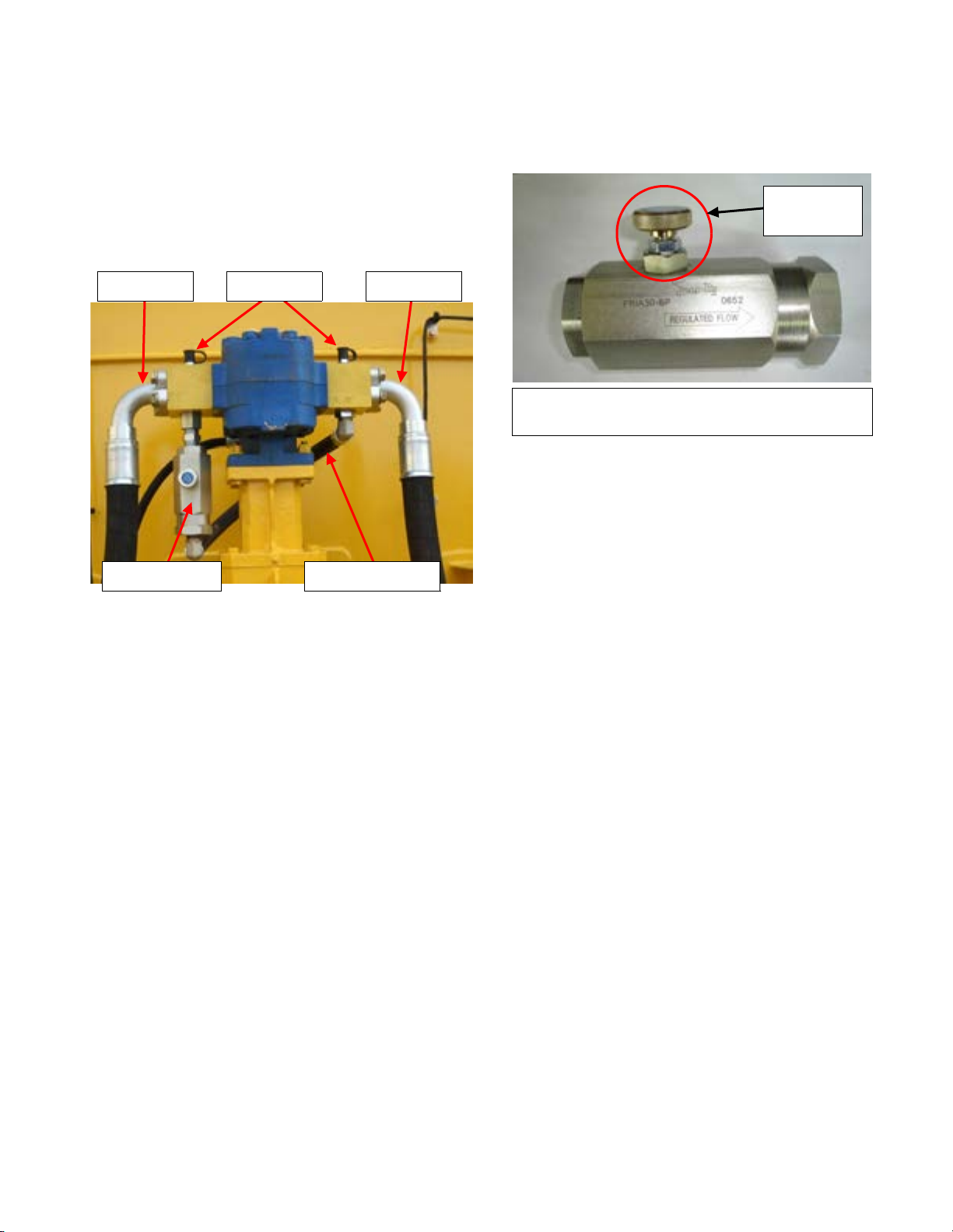
PRESSURE RETURNTEST PORTS
FLOW CONTROL CROSSOVER HOSE
ADJUSTING
KNOB
System Description
HYDRAULIC DRIVE MOTOR SPEED CONTROL
(CROSSOVER ASSEMBLY)
The hydraulic drive motor speed control (Crossover
Assembly) consists of a flow control valve, 2 hydraulic
manifolds, crossover hose and test ports.
MTT-OPS-1
13 Nov 2013
Typical 135 lpm (35 gpm) Adjustable Hydraulic
Flow Control
HYDRAULIC DRIVE MOTOR ACTIVATION
The hydraulic drive motor on MTT’s are typically
driven by the chassis hoist hydraulic system. The
activation can be controlled by the following;
HYDRAULIC FLOW CONTROL VALVE
The hydraulic flow control is directional. The arrow on
the body indicates the direction of oil flow to meter
the bypassing oil. The adjusting knob on the valve
will allow adjustment of the oil flow to bypass the
drive motor, up to135 LPM (35 GPM) or up to
700 RPMs (RPM increase/decrease will vary
depending on the size of hydraulic drive motor the
unit is equipped with). If the flow control is reversed,
the flow control adjusting knob will not function and
the full flow capacity of the valve will bypass. This can
result in water pump rpm being below specifications
with no adjustment capability of the adjusting knob.
By turning the adjusting knob clockwise the
hydraulic oil that is bypassing will be reduced,
increasing the speed of the water pump. Turning the
knob counter-clockwise will increase the volume oil
being bypassed reducing the water pump speed. The
flow control valve is typically mounted on the
PRESSURE manifold of the hydraulic drive motor.
Existing Electric Hoist Valve – The MEGA cab
control pump switch commands the hoist valve to
operate by sending an electric signal to the electric
solenoid on the hoist valve. This operates the hoist
valve, diverting the hydraulic oil to the water pump
drive motor.
Pilot Operated Diversion Valve – A remote
mounted diversion valve that receives an electric
signal from the cab control pump switch to activate a
pilot control to move a spool within the diversion
valve redirecting the hydraulic oil to flow to the water
pump drive motor. Typically this type of valve is
installed between the hoist pump and the
hoist valve.
Existing Mechanically Operated Hoist Valve –
Typically used on early model trucks with a
pneumatic system. This system is operated by the
cab control pump switch sending an electric signal to
an electric/pneumatic solenoid to control a
pneumatic cylinder. When the pneumatic cylinder
operates it moves the spool valve of the hoist valve to
divert hydraulic oil to the water pump drive motor.
2-3
Page 13
MTT-OPS-1
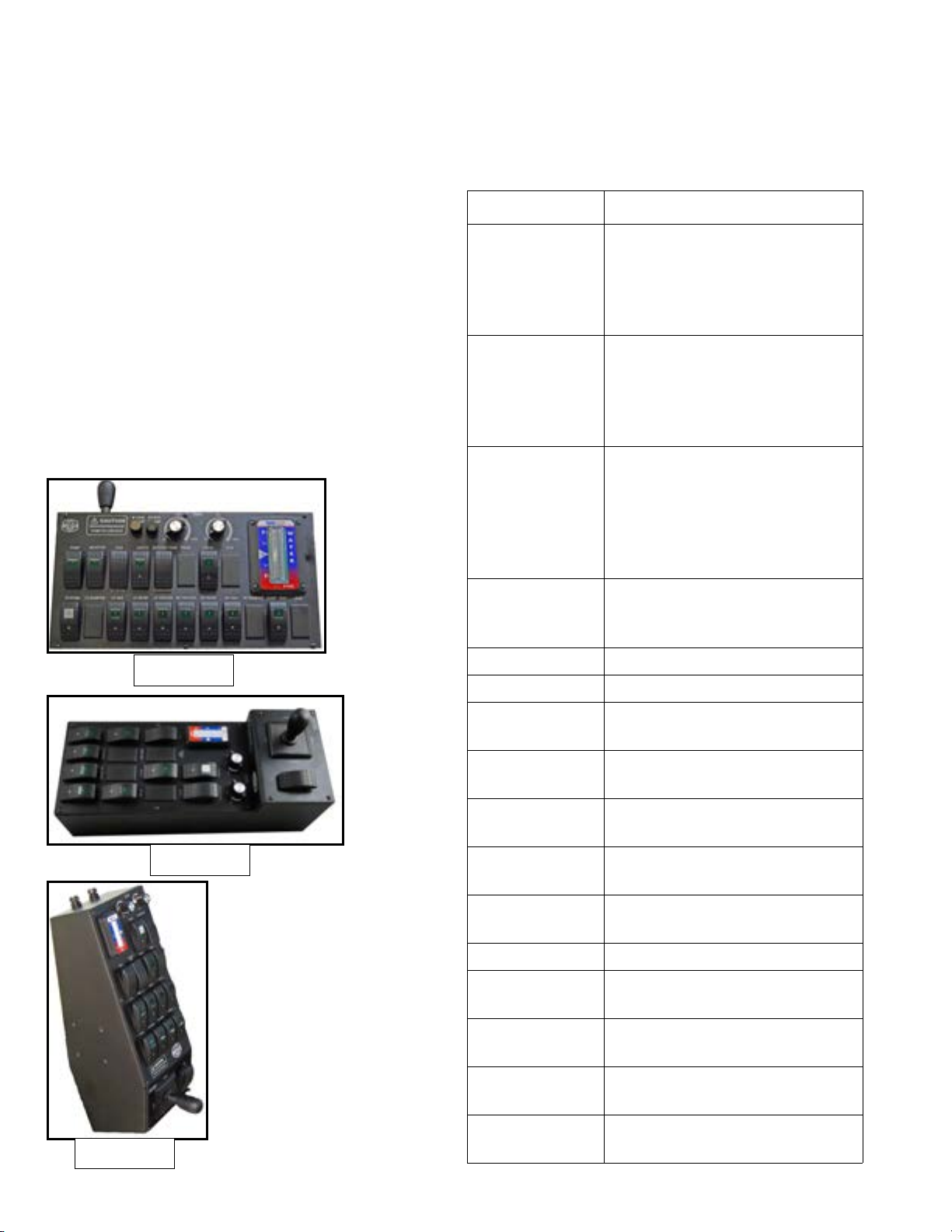
Standard
Step Box
Coffin Box
13 Nov 2013
SECTION 2
System Description
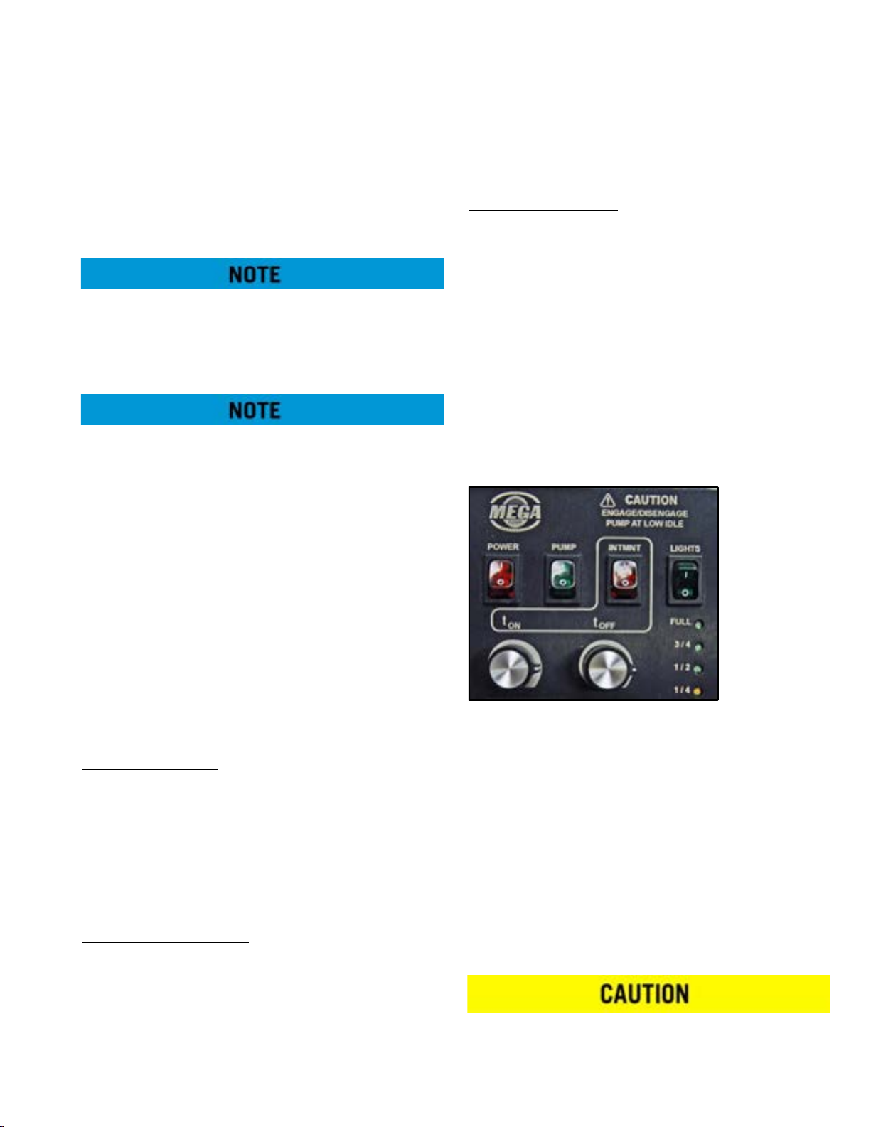
CAB CONTROL SYSTEM (ANALOG)
Multi-function control box that is mounted in the
vehicle cab to control all water tank functions.
Controls are available for the monitor, intermittent
spray, water pump, work lights, foam suppression,
adjustable nozzle, system, spray heads, spray bar,
gravity dump bar and tank drain valve. The control
box also provides indications of tanker water level
and a system fuse holder. The cab controls requires
24 VDC vehicle power to operate.
There are several different configurations of the incab control boxes. Each box is designed and
mounted for a specific prime mover. These
configurations are as follows:
The control functions operate as follows:
Control Function
Joystick Sends command signals to the
logic box (electric monitor) or
hydraulic control valve assembly
(hydraulic monitor) to move the
monitor left, right, up and down.
TIMER ON Sets ON time (variable adjust-
ment 5-100 sec) of selected spray
heads and dump bar when the
timer switch is in the intermittent
position
TIMER OFF Sets OFF time (variable adjust-
ment 5-100 sec) between timer
cycles of selected spray heads
and dump bar when the timer
switch is in the intermittent position.
PUMP Routes vehicle hydraulic system
pressure and flow to the water
pump hydraulic drive motor.
MONITOR Opens the water cannon BFV.
LIGHTS Provides power to work lights.
FOAM Open or closes the foam concen-
trate tank in-line control valve.
INTERMITTENT/
CONSTANT
AUX Reserved for specialized func-
ADJUSTABLE
NOZZLE
AUX Reserved for specialized func-
WATER LEVEL Indicates tank water level.
SYSTEM Provides power for all cab control
LT BUMPER Opens or closes left front bumper
LT VSS Opens or closes left vertical side
Activates or deactivates system
timer function.
tions.
Adjusts monitor nozzle from
FOG/FAN to STREAM.
tions.
functions.
spray head.
spray head.
LT REAR Opens or closes left rear spray
head.
2-4
Page 14
SECTION 2
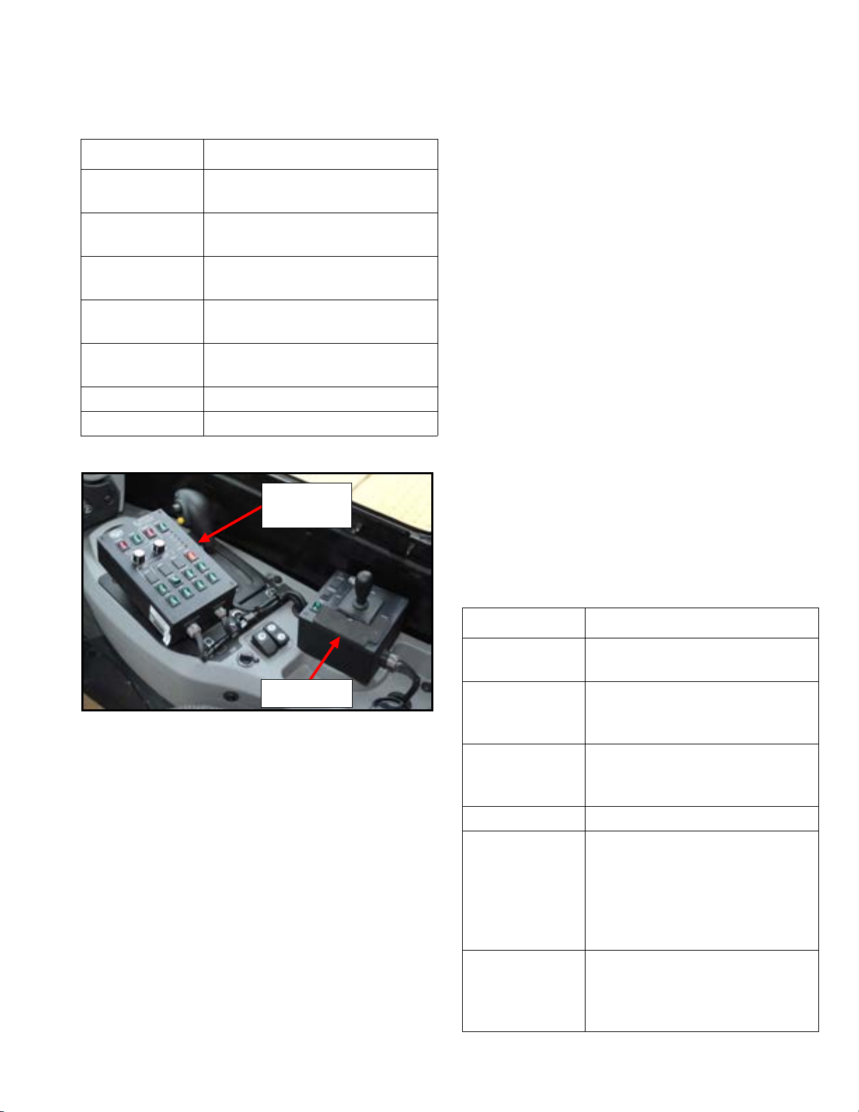
Master
Switch Box
Joystick Box
System Description
MTT-OPS-1
13 Nov 2013
Control Function
LT CENTER Opens or closes left center rear
spray head.
RT CENTER Opens or closes right center rear
spray head.
RT REAR Opens or closes right center rear
spray head.
RT VSS Opens or closes right vertical side
spray head.
RT BUMPER Opens or closes right front
bumper spray head.
DUMP BAR Opens or closes dump bar BFV.
DRAIN Opens or closes tank drain BFV.
CAB CONTROL SYSTEM (DIGITAL)
ABBREVIATIONS AND DEFINITIONS
AUX1 – Auxiliary or additional optional function
BFV – Butterfly Valve
DMPBAR – Dump bar for heavy spray of water close
to ground. Can be either a gravity or pressure dump
bar (pressure dump bar requires water pump
activation to operate).
DRAIN – Drain (gravity or pressure) for
evacuation of water from tank, mounted typically at
the rear of the tank.
KPH – Kilometers per hour
LT V SS – Left Vertical Side Spray
LTC – Left Center Spray Head
LTR – Left Rear Outer Spray Head
MPH – Mile per hour
RAMP – Ramping Control feature. Rate of increase or
decrease in speed of water flow during PUMP
engagement or disengagement
RT VSS – Right Vertical Side Spray
RTC – Right Center Spray Head
RTR – Right Rear Outer Spray Head
This system is designated as a Digital integrated
Spray Control System (DiSCS). The system is
comprised of control boxes, logic controllers, sensors,
and cabling. It is a multi-function control system with
a separate joystick box that is mounted in the vehicle
cab. These two boxes control all water tank functions.
The master switch box operates the water pump,
spray heads, intermittent spray, work lights, hose reel,
dump bar, suction loading, and tank drain valve. The
master switch box also provides indications of tanker
water level and water pump protection features. The
remote mounted joystick box operates the water
cannon, adjustable nozzle and foam suppression. The
cab controls require 12/24 VDC vehicle power to
operate.
The master switch box control functions operate as
follows:
Control Function
POWER Provides power for all cab control
functions.
PUMP Routes vehicle hydraulic system
pressure and flow to the water
pump hydraulic drive motor.
INTMNT Intermittent setting.
Activates or deactivates system
timer function.
LIGHTS Provides power to work lights.
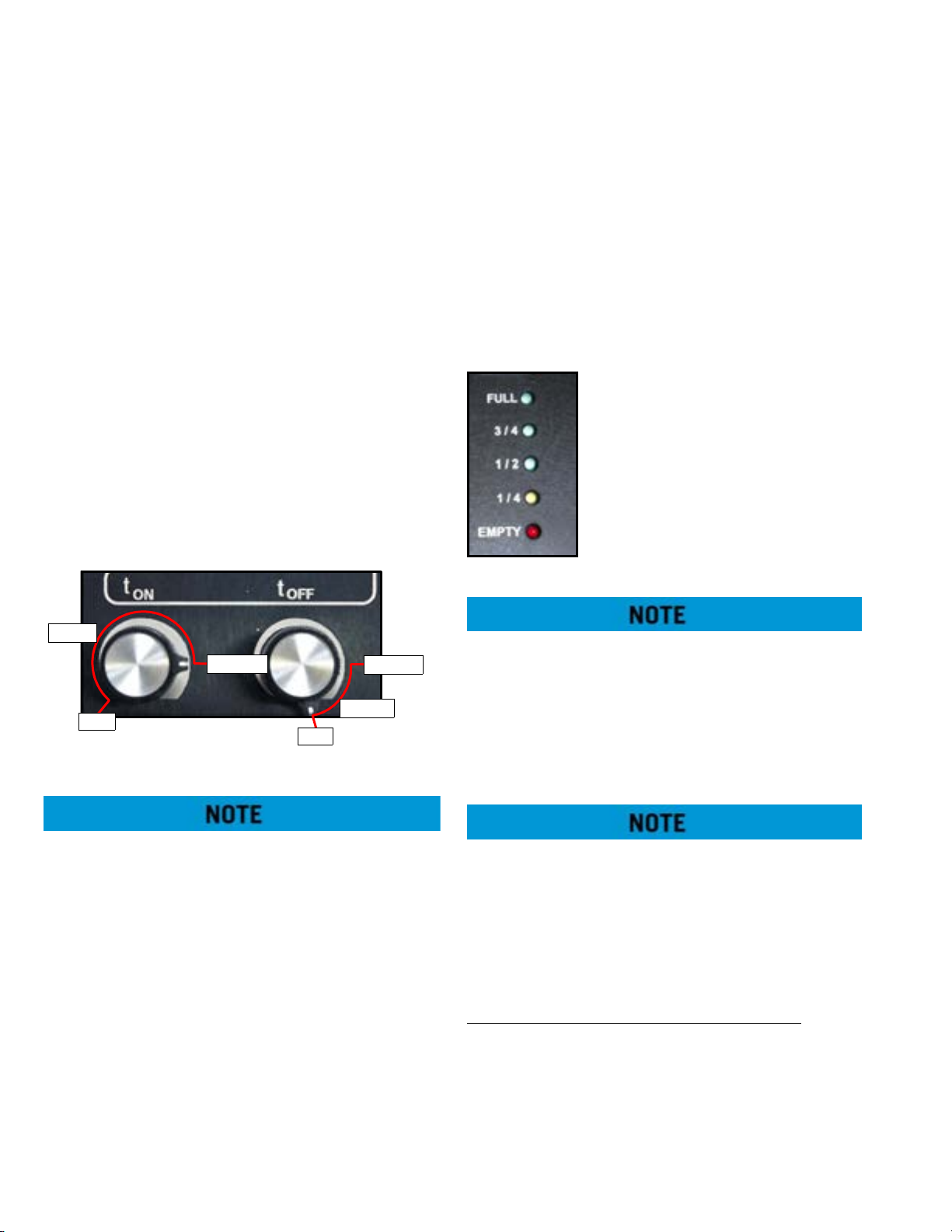
t ON
(Intermittent
timer—manual
mode)
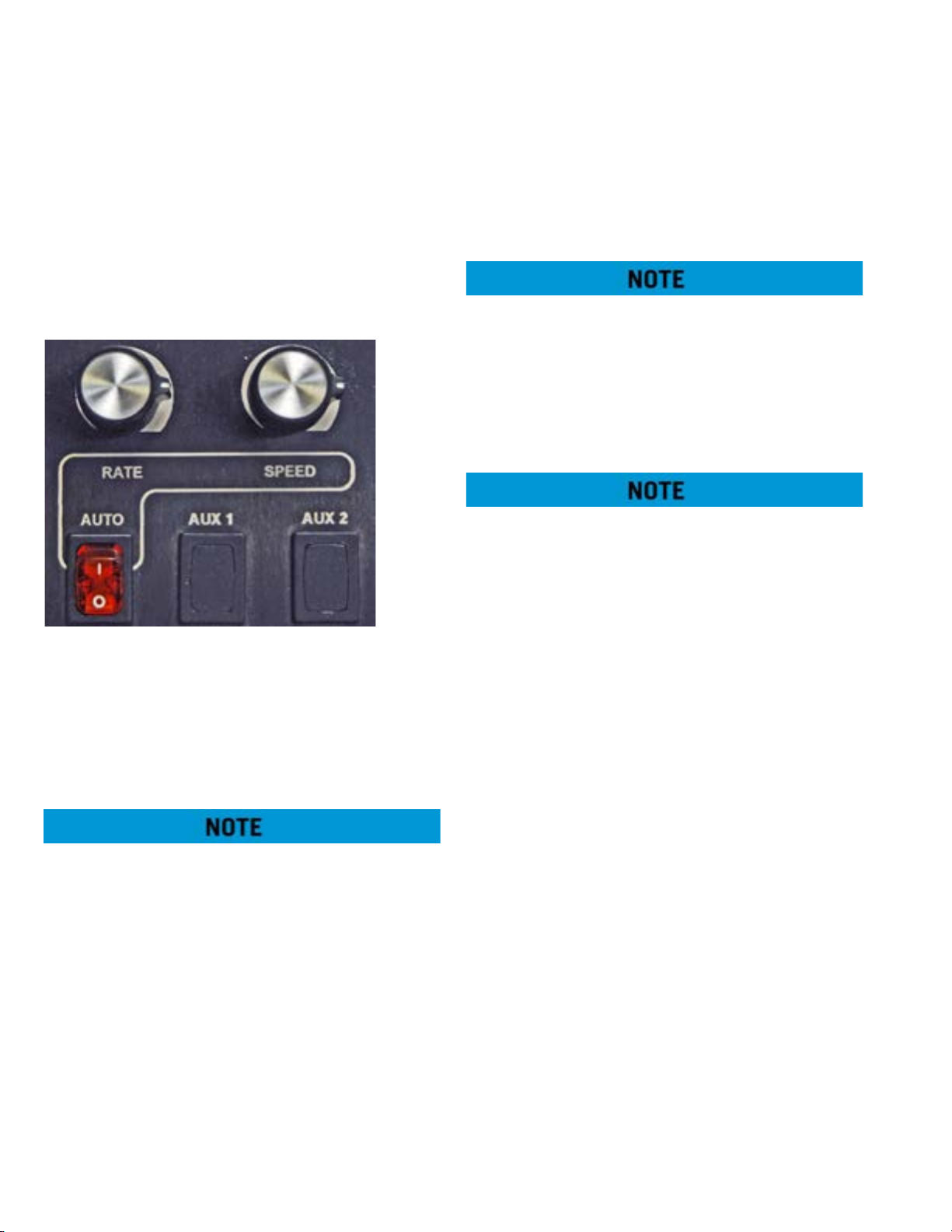
RATE
(GPS Auto Mode)
Sets ON time of selected spray
heads when the timer switch is in
the intermittent (INTMNT) position.
Scale: adjustable from 5 seconds
to 30 seconds.
Increases or decreases amount of
water dispersed during a cycle
when AUTO switch is on (see
extended description).
2-5
Page 15

MTT-OPS-1
13 Nov 2013
SECTION 2
System Description
Control Function
t OFF
(Intermittent
timer—manual
mode)
SPEED
(GPS Auto Mode)
WATER LEVEL Indicates tank water level.
AUTO Controls activation of GPS Auto
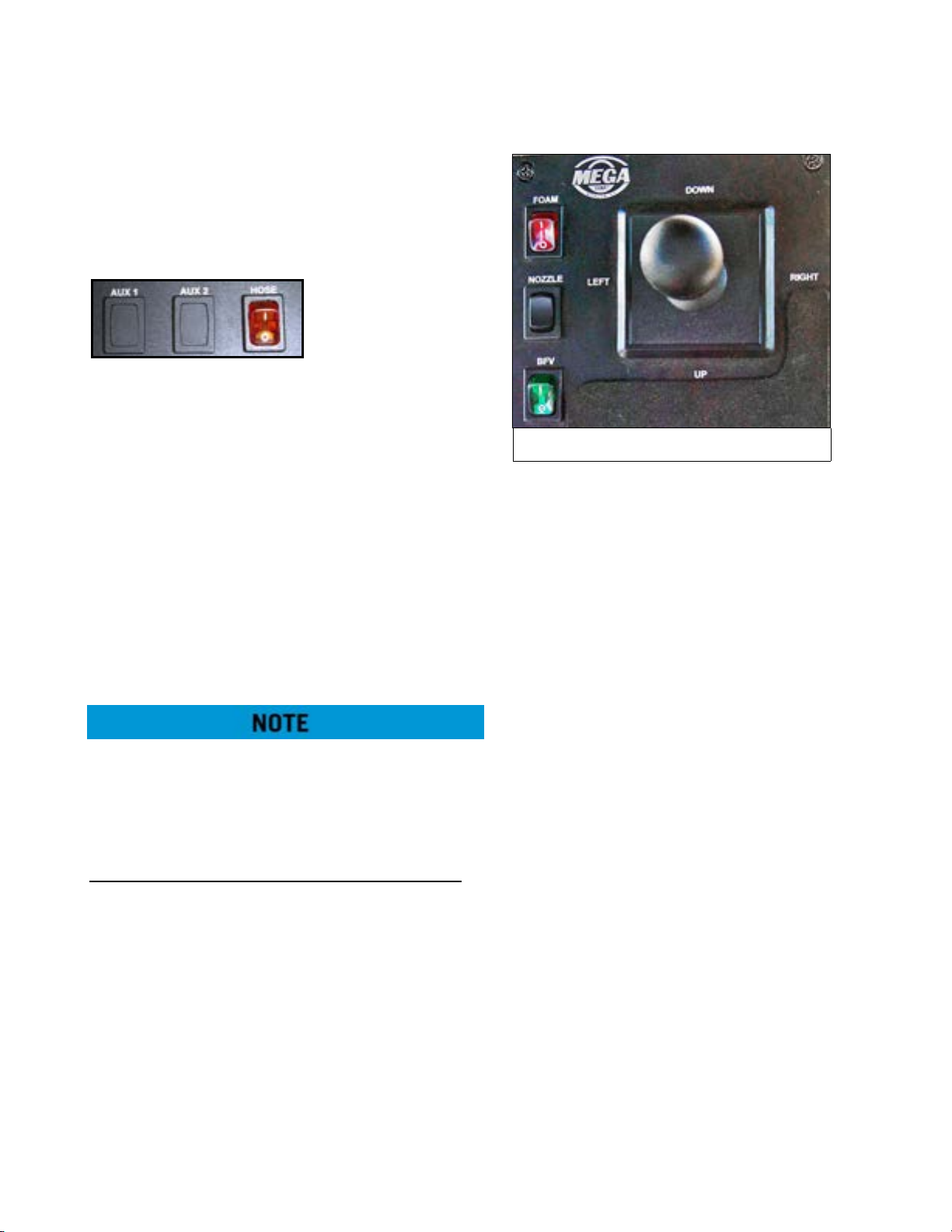
AUX 1 Reserved for user-added option.
AUX 2 Reserved for specialized function.
HOSE Controls activation of hose reel
SUCTION LOAD Controls activation of suction
LT VSS Opens or closes left vertical side
DRAIN Opens or closes tank drain BFV.
DUMP BAR Opens or closes dump bar BFV.
RT VSS Opens or closes right vertical side
Sets OFF time between timer
cycles of selected spray heads
when the timer switch is in the
intermittent (INTMNT) position.
Scale: adjustable from 5 seconds
to 30 seconds.
Sets desired ground speed for
maximum flow (OPEN continuously) of selected spray heads
(see extended description).
mode.
function ONLY.
load station ONLY.
spray head.
spray head.
The joystick box functions operate as follows:
Control Function
Joystick
(LEFT-RIGHT-UPDOWN)
FOAM Open or closes the foam concen-
NOZZLE Adjusts monitor nozzle from FOG
BFV Opens or closes the monitor but-
BASIC SYSTEM THEORY OF OPERATION
Spray system power is provided by chassis 12/24 volt
DC power. Power is routed to cab controllers and
logic control panels by turning on the switched
power via the ignition key switch.
When the chassis ignition switch is turned ON, the
master switch box will undergo a functional self-test.
During this process, ALL LEDs will first turn ON, then
off. While this is occurring, the water level indicator
lights will initially register a FULL tank, and will then
decrease down to EMPTY. The EMPTY light will blink,
and then the water level indicator will count up to
register the current water level of the tank.
Sends command signals to the
hydraulic control valve assembly
to move the water cannon.
trate tank in-line control valve.
to STREAM.
terfly valve.
LT REAR Opens or closes left rear spray
head.
LT CENTER Opens or closes left center rear
spray head.
RT CENTER Opens or closes right center rear
spray head.
RT REAR Opens or closes right rear spray
head.
Cab control power is then activated by turning the
cab control POWER switch ON while logic controllers
are switched on when the chassis ignition switch is
turned ON.
The spray system will function normally when cab
control power is applied (cab control POWER switch
ON) and sufficient water (water level EMPTY light not
flashing) is present. Activation of a specific function is
accomplished by depressing the selected function
switch on the master switch box or joystick box.
Depressing the switch sends a signal to the logic
control panel in the solenoid box to activate a given
function. The logic control then receives the signal
and provides an output command to the given coil or
function.
2-6
Page 16
SECTION 2
System Description
MTT-OPS-1
13 Nov 2013
Once the logic control panel output is processed, the
logic control sends a feedback signal back to the cab
control box to illuminate the LED on the selected
function switch. If the switch LED does not illuminate,
a malfunction may exist in the logic control, wiring
harness or cab control box.
If a function switch is depressed with no
corresponding switch LED, check to ensure system
power switch is ON and the water level empty LED is
not flashing. If the switch LED is not illuminated, a
malfunction may exist.
If the selected function switch LED illuminates and
the component on the water tanker is not
functioning, the component (water-way valve, spray
head or water cannon) may have malfunctioned.
As functions are turned on and off, the water pump
switch will remain illuminated unless all spray system
functions (water-way valves, spray heads or water
cannon) are turned off. The logic control will
automatically turn the water pump off if all valves are
closed to prevent over-temp of the water pump
volute case. As the water level of the tank drops and
the EMPTY LED begins to flash, the logic controls will
deactivate the water pump to prevent cavitation or
dry running of the water pump.
WATER PUMP PROTECTION FEATURES
Soft Start and Stop
from sudden starts and stops whenever the pump is
turned ON or OFF via the switch or any auto/logic
control feature. This is accomplished by the logic
control system slowly commanding the appropriate
proportional hydraulic control valve to open or close
slowly to prevent hard starts or stops that can reduce
water pump service life.
Low Water Protection
automatically turned off by the logic control system
when a low water condition is detected. The logic
control system monitors tank water level and
commands the water pump to turn off when a
predetermined low water condition is noted. This
prevents the water pump from running in a dry sump
– The water pump is protected
– The water pump is
that will over-heat shaft seals due to lack of water.
Continued use will damage the shaft seals.
No-Flow Conditions
automatically turned off after about 100 seconds,
whenever all water discharge valves are closed. The
logic control system monitors all discharge valves
and begins a TIME OUT cycle to turn off the water
pump after about 100 seconds. Any time a discharge
valve is opened during the timing cycle, the clock is
reset. This feature prevents the water from heating
up due to the water pump impeller spinning in a
sump with no flow. The heating of the static water
will also heat the water pump causing deterioration
of grease and premature bearing failure.
MASTER SWITCH BOX EXTENDED FUNCTION
DESCRIPTIONS
POWER – Turns POWER ON and OFF to cab controls
and digital controllers.
PUMP – Sends request for pump engagement/
disengagement to the digital control processor. The
digital controllers will activate the hydraulic circuit to
slowly ramp-up or ramp-down the water pump.
The water pump switch will flash whenever the
switch is on and the following conditions apply:
• Low water condition is sensed (EMPTY LED is
flashing).
• No flow condition is sensed (for about 100 seconds, no waterway valves are open)
Engaging/disengaging the water pump above LOW
IDLE will result in water pump component damage
and reduced service life.
– The water pump is
2-7
Page 17
MTT-OPS-1
3s - 15s
zero
max
15s - 30s
3 o’clock
3 o’clock
13 Nov 2013
SECTION 2
System Description
INTMNT (Intermittent Function)
Intermittent spray function sends request for
adjustable timing of spray head and dump bar as
commanded by the tON and tOFF dials.
Intermittent will only operate if at least 1 discharge
function (spray head or dump bar) switch is
activated. Water discharge can be stopped at any
time when in INTMNT mode by turning discharge
function switches OFF. The timer will continue to
cycle even if no water is being sprayed
The tON and tOFF adjusting knobs command timing
as follows:
• t ON – Adjusts spray head ON time.
• t OFF – Adjusts spray head OFF time.
The relationship between dial rotation and ON/OFF
time is as follows:
cycles automatically to an OFF cycle, INTMNT switch
and function switch LEDs will extinguish. As the ON
cycle is about ready to engage, the INTMNT switch
LED will flash 3 times at the end of the OFF cycle to
indicate the selected spray functions are about to be
turned ON. These light conditions will change back
and forth until intermittent or function switches are
turned off.
Water Level Indicator – Indicates tank water level as
sensed by the water level pressure
sensor in the rear of the water tank.
When the red EMPTY LED light
flashes, the tank is at minimum
water level. This low level signal is
also sent to the logic control to
automatically ramp-down the water
pump to prevent component
damage. Water pump operation can
only be restored if sufficient water is
in tank to extinguish EMPTY light.
– zero to 3 o’clock position: 3 sec to 15 sec
– 3 o’clock to max position: 15 sec to 30 sec
The above time ON/OFF scale applies to firmware
versions 3.7.0 and above. For firmware versions 3.6.x
and below, the range is 5 seconds to 30 seconds,
scaled linearly across the rotation of the dial.
The intermittent function will turn selected spray
head or dump bar on and off. Duration of tON and
tOFF cycle times are selected by setting the
appropriate dials on the master switch box. When the
INTMNT switch is ON and functions are selected, the
operator will observe different switch LEDs
conditions to indicate operation within the tON and
tOFF cycles. When a selected function switch (spray
head or dump bar) is operating during an ON cycle,
the selected function switch LED will be illuminated
as well as the INTMNT switch LED. When the INTMNT
In order to re-activate the water pump after lowwater shut-off, first fill the water tank with sufficient
water capacity to permit pump operation. Then turn
the PUMP and POWER switches OFF. Cycle the chassis
ignition key OFF/ON. Wait for the Master Switch Box
to complete its lights check. Then, if the water level
gauge reads above EMPTY, turn the POWER and the
PUMP switches on.
Certain terrains and water level fluctuations may
allow low water protection to capture a low water
level condition, causing the pump ramp-down. If
conditions allow water pump activation after water
level/terrain fluctuations have ceased, then the water
pump may be re-activated by following the steps in
the previous note.
Pressure Discharge Function Descriptions:
Spray Heads – Control opening or closing of the
associated valve when selected, or automatically
controlled when INTMNT function is selected.
Dump Bar (Pressure) – Controls opening or closing
of the BFV when selected, or automatically controlled
when INTMNT function is selected.
2-8
Page 18
SECTION 2
Joystick Box Functions
System Description
Suction Load - Allows continuous hydraulic water
pump drive circuit flow during a low water level
condition. Also disables use of any other master
switch box waterway valve
AUX FUNCTIONS
AUX 1 – Sends request for operation of auxiliary
functions or additional non-standard options of spray
system. This function is unique to a specific tank
serial number.
MTT-OPS-1
13 Nov 2013
AUX 2 (Suction Load Station) – If equipped, sends a
request to the hydraulic water pump drive circuit to
allow suction load pump drive motor operation
during a low water level condition while also
disabling the timed-out function. When turned ON,
the AUX2 switch LED will flash rapidly and all
pressure discharge functions are disabled.
HOSE – Allows continuous water pump operation for
hose reel use while also disabling the use of any
other master switch box waterway valves.
Ensure all discharge function switches are OFF when
using HOSE function. Activating the HOSE switch
requests all discharge function to turn OFF (All Spray
heads, Water Cannon BFV, Drain, Dump Bar and
FOAM).
Non-Pressure Discharge Function Descriptions:
Dump Bar (Gravity) – Controls opening and closing
of the BFV when selected, or automatically controlled
when the INTMNT function is selected.
JOYSTICK BOX EXTENDED FUNCTION
DESCRIPTIONS
The joystick box houses logic controls for the joystick
and the FOAM, NOZZLE, and BFV switches. These
switches and the joystick control requests for water
cannon operation.
FOAM – Sends request for FOAM agent valve to open
or close.
NOZZLE – Sends request for adjustable nozzle on
water cannon to move from FAN/FOG to STREAM
spray patterns.
BFV – Sends request to open or close butterfly valve.
The butterfly valve controls water flow to the Water
Cannon. Activating the BFV switch requests the water
PUMP to stay ON with NO other pressure discharge
functions activated providing, sufficient water is in
tank to allow command to be sent.
JOYSTICK – Sends requests for rotation and
elevation motion for water cannon operation.
GROUND SPEED SENSING (GPS) CONTROL
The MEGA ground speed sensing control system is an
independent and self-contained GPS unit and
antenna that provides speed information to the
existing Mega Digitally Integrated Spray Control
System (DiSCS). The DiSCS’s logic control uses the
ground speed signal to automatically cycle and pulse
spray heads to obtain a desired lay-down of water
regardless of ground speed. The system contains
controls to adjust maximum water discharge speed
as well as actual rate of flow. This automatic control
reduces water usage and prevents over-watering of
haul roads and intersections.
The system will automatically close all discharge
functions (spray heads) below 5 KPH/3 MPH to
prevent puddling of water at intersections. The
system also opens selected discharge functions
when accelerating above 5KPH/3 MPH.
2-9
Page 19
MTT-OPS-1
13 Nov 2013
SECTION 2
System Description
The system warns the operator of all malfunctioning
system functions and provides full manual control of
all spray system functions in the event of an AUTO
mode failure. All automatic system protection
features of low water level conditions, no-flow
conditions and water pump soft start/stop feature
still operate normally in the AUTO mode.
GPS EXTENDED FUNCTION DESCRIPTIONS
SPEED – Above what vehicle speed the command is
sent for maximum flow of all selected discharge
functions (spray heads). Below this vehicle speed,
timed cycles and/or reduced water volume flow
occur.
The scale for the SPEED function is 0 KPH/0 MPH (Full
LEFT) to 48 KPH/30 MPH (Full RIGHT).
When vehicle speed goes below the set SPEED,
application rate of water discharged will be either
pulse the requested discharge functions and/or
reducing the number of discharge functions based
on the RATE selected.
IF vehicle speed is GREATER than set SPEED the RATE
has little or no effect on water discharge. Typically all
requested pressure discharge functions are ON and
no timing cycle.
AUTO – This function has priority over intermittent
mode. The intermittent light will illuminate steadily
when operating conditions are met and AUTO is ON.
AUTO enables vehicle speed signal from the GPS
module to activate the speed sensing mode, and
operates the spray system based on RATE and SPEED
adjustments. Pulse will begin when the AUTO
function requests reduced volume.
Near or below 4.8 KPH/3 MPH, AUTO will switch to
INTERMITTENT mode and discharge functions may
operate continuously or ramp down the water pump
to OFF. When vehicle speed rises above 4.8 KPH/3
MPH, AUTO will resume control of the system.
RATE – Is the distance traveled/time for spray head
ON cycle.
•Knob turned counterclockwise reduces ON distance/ ON time
• Knob turned clockwise increases ON distance/
ON time
Reduced Volume Mode – Reduction in discharge
volume by reducing the number of spray heads
requested to activate.
• If 4 rear spray heads are requested, reduced volume allows only the 2 outer spray heads to turn
ON and the 2 center spray heads are OFF.
• If 3 rear spray heads are requested 1 spray head
will be OFF, typically the center head adjacent to
the outer head requested.
• If 2 spray heads are requested 1 spray head will
be OFF typically the center spray head unless no
center spray heads are requested, then NO spray
heads will be OFF.
Pulsing – Reference to Pulse Width Modulation or
ON/OFF cycle.
2-10
Page 20
SECTION 2
System Description
MTT-OPS-1
13 Nov 2013
WATER CANNON SYSTEM
The system is comprised of a water cannon (hydraulic
or electric), hydraulic control valve assembly or logic
box, butterfly valve assembly, nozzle and controls.
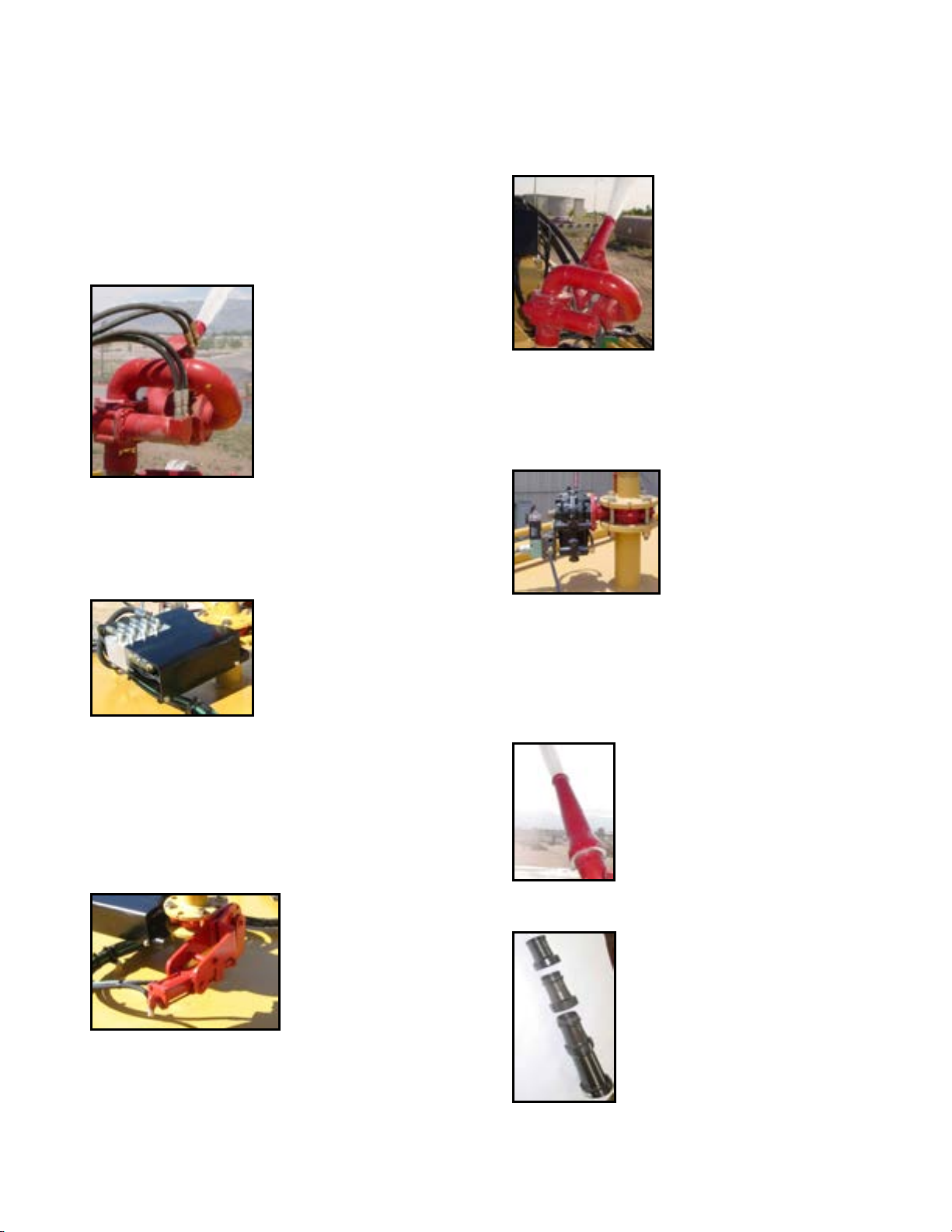
WATER CANNON (Hydraulic)
cannon is threaded to a flanged pipe that mounts
directly above the BFV. The water cannon also
provides mounting for a variety of different nozzles.
HYDRAULIC CONTROL VALVE ASSEMBLY
the cab control box. A pressure relief valve is
incorporated in the manifold block to protect the
water cannon system against any over pressurization
conditions. The assembly is mounted to the tank
lower flange and receives hydraulic pressure from the
vehicle hydraulic pump.
A metal waterway that directs
a stream of water in both
elevation (up-down) and
rotation (right-left). Hydraulic
motors move the waterway
based upon hydraulic flow
from the hydraulic control
valve assembly as
commanded by the cab
control joystick. The water
The assembly contains three
hydraulic solenoid valves that
direct hydraulic pressure to
the hydraulic motors on the
water cannon and BFV
cylinder as commanded by
WATER C ANNON (ELECTRIC)
A metal waterway that directs a
stream of water in both
elevation (up-down) and
rotation (right-left). 24 VDC
electric motors move the
waterway based upon filtered
electronic signals from the logic
box as commanded by the cab
control joystick. The water
cannon is threaded to a flanged pipe that mounts
directly above the BFV. The water cannon also
provides mounting for a variety of different nozzles.
ELECTRO-PNEUMATIC BFV ASSEMBLY
An electro-pneumatic valve that
controls the flow of water to the
water cannon. A 24 volt DC
solenoid receives commands
from a cab control MONITOR /
BFV switch through the logic
box to route pressurized air to
an air chamber which opens or closes a 3” valve. The
assembly is clamped between upper and lower pipe
flanges.
WATER CANNON NOZZLES AND STREAM SHAPERS
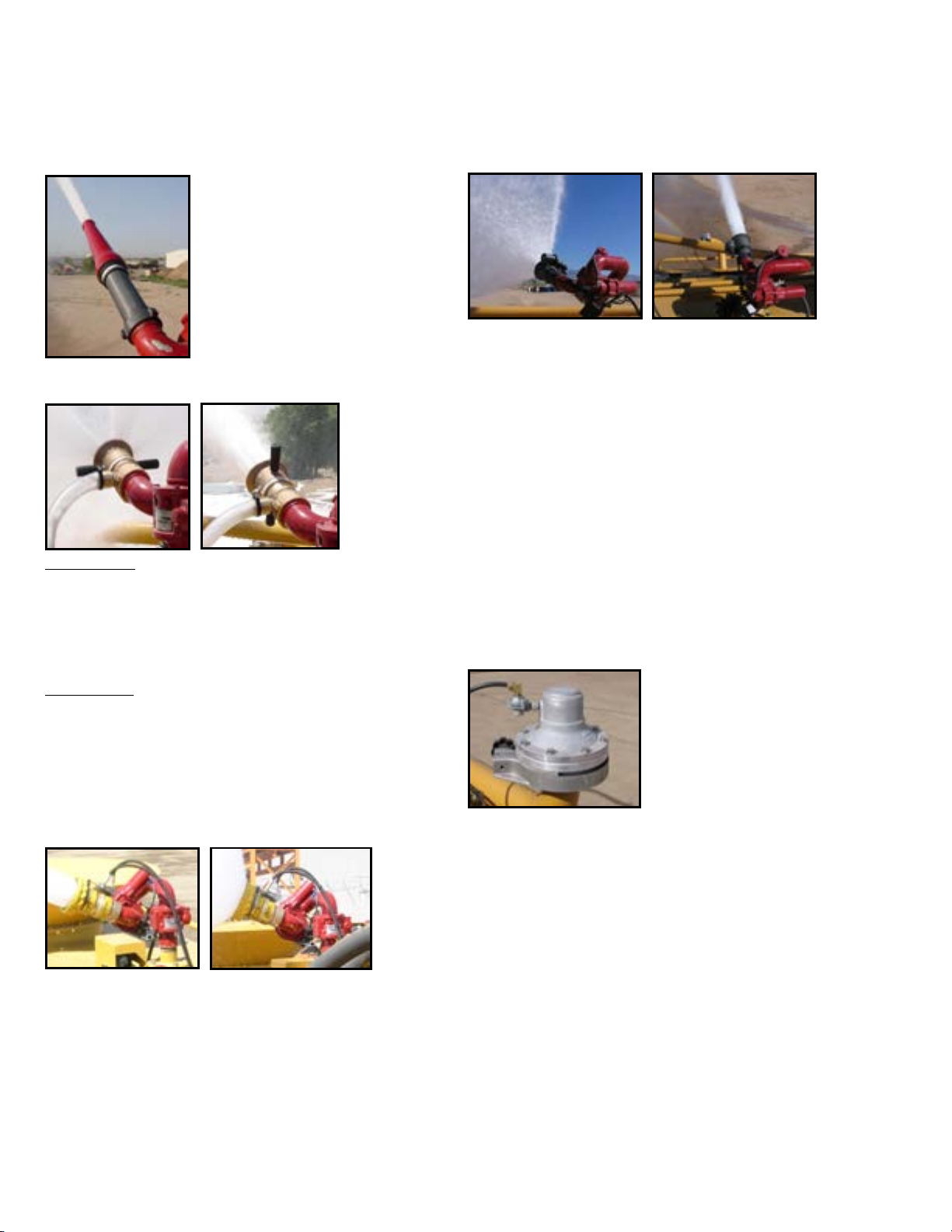
Smooth Bore Nozzle
A cone shaped 1.5” diameter nozzle
that directs water flow. The nozzle
has a built in stream shaper that
smooths water flow to increase water
stream distance.
HYDRAULIC BFV ASSEMBLY ASSEMBLY
A hydraulically operated
valve that opens or closes
to control water flow to
the water cannon. The
hydraulic cylinder receives
hydraulic pressure from
the hydraulic control valve
or solenoid control box assembly as commanded by
the cab control water cannon switch. The assembly is
clamped between upper and lower pipe flanges.
Smooth Bore (Stackable)
A segmented cone shaped nozzle
that directs water flow. The nozzle
opening is adjusted by removing
segments to acquire the most
efficient nozzle opening for a given
water pump operating pressure.
Nozzle segment diameters are 1?”,
1½”, 1¾” and 2”. The nozzle requires
and in-line stream shaper to increase
water stream distance.
2-11
Page 21
MTT-OPS-1
13 Nov 2013
SECTION 2
System Description
In-Line Stream Shaper
A performance enhancer that is
mounted between the water
cannon outlet and the selected
straight bore nozzle. The stream
shaper pathway is a honeycomb
style channel designed to
efficiently shape a water stream
to maximum water stream
distance.
Manual Adjustable Nozzle
Fog/Stream:
allows the operator to manually adjust selected
water stream patterns from fog to stream. Some
nozzles are configured for fire suppression foam
eduction.
Fan/Stream:
allows the operator to manually adjust selected
water stream patterns from flat fan to stream. The flat
fan pattern orientation is adjustable from horizontal
to vertical by reorienting the nozzle on the water
cannon.
Remote Adjustable Nozzle (Electric/Hydraulic)
A modified straight bore nozzle that
A modified straight bore nozzle that
Fan/Stream
A modified straight bore nozzle that allows the
operator to remotely adjust selected water stream
patters from flat fan to stream from the cab control.
The nozzle inner or outer barrel is moved by an
electric actuator to obtain the fan or stream pattern.
The flat fan pattern orientation is adjustable from
horizontal to vertical by reorienting the nozzle on the
monitor.
SPRAY SYSTEM
The spray head system consists of 4, 6 or 8 hydraulic
or pneumatic actuated spray heads, cab controls,
solenoid control box assembly and hydraulic or
pneumatic hosing.
PNEUMATIC SPRAY HEAD
A two piece aluminum valve
body and adjustable ring
mounted to a water supply
header pipe. The upper
portion of the valve body is
an air chamber with a
diaphragm and guide disk
assembly attached to the bottom. The air chamber
receives pressurized air from the solenoid control box
as commanded by the cab control switch. When the
upper portion of the valve body is pressurized the
guide disk will seal the opening on the lower portion
of the valve and stop water flow.
A modified straight bore nozzle that allows the
operator to remotely adjust selected water stream
patterns from fog to stream from the cab control. The
nozzle inner or outer barrel is moved by an electric or
hydraulic actuator to obtain the fog or stream
pattern. Some nozzles are configured for fire
suppression foam eduction.
When the cab control system is OFF and the water
pump is OFF the air chamber incorporates a spring
that will apply pressure to the guide disk assembly
and seal the opening on the lower portion of the
valve and stop flow. When air pressure is removed
from the upper portion of the valve body when the
water pump is ON and the cab control switch ON,
pressurized water from the header pipe will unseat
the guide disk and water will flow from the lower
portion of valve.
2-12
Page 22
SECTION 2
1/4” Opening
3/8” Opening
Pneumatic
Pneumatic
System Description
MTT-OPS-1
13 Nov 2013
HYDRAULIC SPRAY HEAD
A two piece aluminum valve
body, hydraulic cylinder and
adjustable ring mounted to a
water supply header pipe. The
upper portion of the valve body
contains a hydraulic cylinder
that receives hydraulic pressure
from the system solenoid control box as commanded
by the cab control switch. When the hydraulic
cylinder on the upper portion of the valve body is
pressurized the cylinder extends to contact the guide
disk and seal the opening on the lower portion of the
valve and stop water flow. When the cab control
system is OFF and the water pump is OFF the upper
valve body incorporates a spring to apply pressure to
the guide disk to seal the opening on the lower
portion of the valve and stop flow. When the spray
head switch is turned on hydraulic pressure retracts
the hydraulic cylinder and pressurized water from the
header pipe will unseat the guide disk and water will
flow from the lower portion of valve.
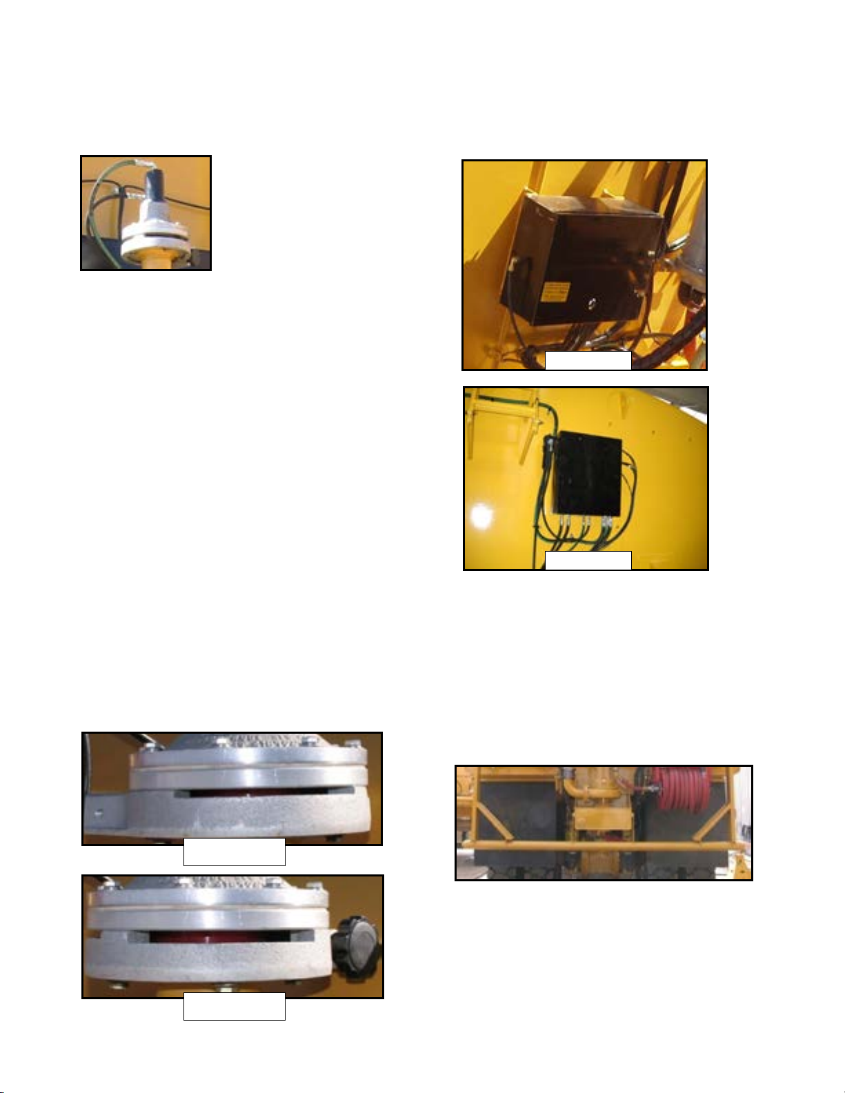
SOLENOID CONTROL BOX
Spray Head Adjustable Rings
The adjustable ring is used to control fan width and
water flow. The ring may be loosened and rotated to
expose more or less of the lower valve opening to
control water fan width from 15° to 90°. The ring also
may be used rotated to a 1/4” or 3/8” slot as shown in
figure 2-2 and 2-3 to increase or decrease overall
water flow. The greater the opening, the greater the
water flow.
The control box assembly is mounted to the forward
bulkhead or top skin of the MTT. The assembly
contains pneumatic or hydraulic solenoid valves that
direct pneumatic or hydraulic pressure to the spray
head as commanded by the cab control box. The
solenoids receive pneumatic pressure from the
vehicle or hydraulic pressure from water pump oil
circuit and 24 VDC power from the cab control box.
DUMP BAR
A spray bar that contains several rows of 3/8” drain
holes to dispense water. A hydraulically operated BFV
controls the water supply to the dump bar. The BFV is
controlled electrically from the cab control box and is
actuated by a hydraulic cylinder. The actuators
receive hydraulic pressure from the solenoid control
box assembly. Dump bars can be either gravity or
pressure fed.
2-13
Page 23

MTT-OPS-1
13 Nov 2013
SECTION 2
System Description
HOSE REEL
A reel assembly that is located on the bottom aft end
of the water tank fitted with a 1” or 1.5” diameter
reinforced rubber hose and a fire fighting style
nozzle. The hose reel assembly receives pressurized
water from the pressurized manifold on the back of
the tank to operate.
TANK DRAIN
FIRE SUPPRESSION SYSTEM
A system that consists of a 120 or 60 gallon stainless
steel holding tank, an electric or pneumatic actuated
shut-off valve, in-cab control switch, hosing and a
foam eduction nozzle mounted to the water cannon.
FOAM CONCENTRATE TANK
A stainless steel tank
mounted in the forward
upper portion of the water
tank. The holding tank
contains a supply tube that
extends to the bottom of the
tank and connected to a
flexible hose at the top of the tank and then routed to
the foam agent shut-off valve. The tank also contains
a pressure/vacuum cap which keeps foreign matter
out of the tank while providing for pressure relief and
air displacement during temperature changes.
ELECTRIC/PNEUMATIC SHUT-OFF VALVE
The in-line shut-off valve is mounted on the foam
tank upper lip and is controlled by the in-cab control
FOAM switch. The shut-off valve is actuated by
either an electric or pneumatic actuator that is
controlled by the in-cab control switch. Once the
shut-off valve is opened, foam concentrate will flow
from the holding tank to the monitor nozzle if the
monitor and water pump switches are ON.
A hydraulic BFV attached to the water tank pressure
pipe is used to drain water from the water tank. The
BFV is controlled electrically from the cab control box
and is actuated by a hydraulic actuator. The actuators
receive hydraulic pressure from the solenoid control
box assembly. Tank drains can be either gravity or
pressure fed.
FOAM EDUCTION NOZZLE
A manual or remote
adjustable (fog/stream)
nozzle is attached to the
water cannon waterway. The
nozzle inner housing uses
monitor high pressure water
to create a venture effect
that will create a suction
force that pulls foam concentrate from the holding
tank. Once foam concentrate is flowing, the nozzle
proportions foam concentrate, water and air to
produce finished foam. The nozzle can be adjusted to
allow control of foam solution at a rate of 1%, 3% or
6%. Rate adjustment is obtained by replacing a
removable disk.
2-14
Page 24

SECTION 2
System Description
WATER CIRCULATION SYSTEM
A system that consists of a hydraulic butterfly valve
assembly and a perforated 4” pipe located inside the
water tank. The system diverts the flow of water from
the spray system to the perforated pipe, circulating
the water in the tank. The circulation valve must be
closed to operate the spray system, and water
cannon.
SUCTION LOADING (IF EQUIPPED)
MTT-OPS-1
13 Nov 2013
A second water pump mounted typically to the water
pump sump at the rear of the MTT. The suction
loading station is equipped with a manual diversion
valve that will switch the hydraulic oil flow from the
main discharge pump drive motor to the suction
loading pump drive motor. When oil is diverted to
the suction loading drive motor it can pull water from
a holding pond and fill the MTT. The suction loading
option includes lengths of 4” suction hose equipped
with quick couplers and a check valve inlet foot with
a debris screen. The suction hoses are typically stored
in tubes either built into the MTT or a hanging tube
arrangement.
2-15
Page 25

MTT-OPS-1
13 Nov 2013
SECTION 2
System Description
2-16 (Blank)
Page 26

SECTION 3
Limitations
Contents
Water Pump .....................................................................3-1
WATER PUMP
The following cautions are operational limitations of
Mega water pumps. Failure to heed these cautions
may result in reduced pump life and severe water
pump damage.
MTT-OPS-1
13 Nov 2013
Water pump RPM must not exceed the specifications
listed below with engine at HIGH IDLE. Failure to
ensure water pump speed is at or below
specifications will result in reduced spray system
component service life.
Do not operate the water pump in a dry sump.
Operating the water pump with a dry sump will result
in water pump component damage and reduced
service life.
Engaging/disengaging the water pump above LOW
IDLE may result in water pump component damage
and reduced service life.
Limit water pump operation to 2.5 minutes when in a
no-flow condition (not flowing water through spray
heads, dump bar, water cannon, drain valve or hose
reel). Water pump operation in a no flow condition
will cause overheating of the water pump and
damage to the shaft bearings and seals.
PUMP MODEL RPM
M-4 PUMP 1,900 ± 50
B-4 PUMP 2,000 ± 50
M-4B PUMP 2,000 ± 50
If water pump RPM is to out of the desired range,
adjust the water pump hydraulic drive motor flow
control valve to obtain specified RPM.
Avoid any sudden stoppage of water pump e.g.;
disengaging water pump above LOW IDLE. Stopping
water pump suddenly above LOW IDLE will result in
shaft, impeller and drive motor damage.
3-1
Page 27

MTT-OPS-1
13 Nov 2013
SECTION 3
Limitations
3-2 (Blank)
Page 28

SECTION 4
Normal Operations
Contents
MTT-OPS-1
13 Nov 2013
Description .........................................................................4-1
Before Operations ............................................................4-1
Operations ..........................................................................4-2
DESCRIPTION
This section provides the vehicle operator with step
by step operating procedures for the installed MTT
system. The information is separated into before
operations, operations and after operations. A pocket
size checklist of all listed procedures is also provided
in the Appendix for use in the vehicle cab.
BEFORE OPERATIONS
These procedures are used to perform a walk-around
inspection of the MEGA water tanker system before
use or the beginning of a shift. This inspection is in
addition to and does not replace the vehicle
manufacturer’s inspection requirements.
1. Chocks – As Required
2. Vehicle Parking Brake – ON
3. Cab Control Switches – SET OFF
After Operations ............................................................... 4-6
Cold Weather Operation and Storage ...................... 4-6
10. Chassis Pivot Bore Pins – INSTALLED AND
SECURED
11. Tank Drain Petcocks – CLOSED
12. Spray Heads – SECURED & SET
13. Water Pump Assembly – CHECKED
a. Water Pump – Check to ensure volute case
drain valve is closed.
b. Water pump and drive motor for evidence of
overheating.
14. Hose Reel – CHECKED
15. (Rear Bulkhead Location Only) Solenoid
Control Box – CHECKED.
16. MTT RH Hydraulic Hosing & Cabling – CHECKED
FOR SECURITY AND LEAKS.
4. (If Equipped) Foam Concentrate Level –
CHECKED. At least 1” from the top of the foam
tank.
Ensure PPE fall arrest harness is worn, adjusted
properly and attached to an anchor point. Failure
to use PPE properly may result in personnel injury
or death.
5. Water Cannon – CHECKED & SECURED
a. Nozzle – Check for security and kinking of
foam concentrate supply line.
6. Solenoid Control Box – CHECKED AND SECURED
7. MTT Front Mounts – CHECKED AND SECURE
8. Vehicle Hydraulic Tank – SERVICED
9. MTT LH Hydraulic Hoses and Cabling – CHECKED
FOR SECURITY & LEAKS.
17. (If Equipped) Front Bumper Spray Heads &
Plumbing – SECURED AND SET.
4-1
Page 29

MTT-OPS-1
13 Nov 2013
SECTION 4
Normal Operations
OPERATIONS
Use these procedures to safely operate the standard
and optional systems installed on the MEGA water
tanker.
Limit water pump operation to 2.5 minutes when in a
no-flow condition (not flowing water through spray
heads, dump bar, monitor, drain valve or hose reel).
Water pump operation in a no flow condition will
cause overheating of the water pump and damage to
the shaft bearings and seals.
SPRAY HEAD SYSTEM
Operating more than 4 spray heads simultaneously
will greatly reduce the width and flow of active spray
heads.
1. Cab Control SYSTEM/POWER Switch – ON
GPS AUTO MODE
1. Cab Control POWER Switch – ON
2. PUMP Switch ON
Engaging/disengaging the water pump above
LOW IDLE may result in water pump component
damage and reduced service life.
3. AUTO – SET AS REQUIRED
a. RATE and SPEED Dials – SET
b. AUTO Switch – ON
4. Individual Spray Head Switches – ON
Once operations are complete:
5. Individual Spray Head Switches – OFF
6. PUMP Switch – OFF
2. INTERMITTENT TIMER – SET
a. TIMER ON/OFF Dials – SET
b. INTERMITTENT Switch – SET
3. PUMP Switch – ON
Engaging/disengaging the water pump above
LOW IDLE may result in water pump component
damage and reduced service life.
4. Individual Spray Heads – SELECTED
Once operations are complete:
5. PUMP Switch – OFF
Engaging/disengaging the water pump above
LOW IDLE may result in water pump component
damage and reduced service life.
6. Cab Control SYSTEM/POWER Switch – OFF
Engaging/disengaging the water pump above
LOW IDLE may result in water pump component
damage and reduced service life.
7. Cab Control POWER Switch - OFF
DUMP BAR
1. Cab Control SYSTEM/POWER Switch – ON
2. INTERMITTENT – SET AS REQUIRED
a. TIMER ON/OFF Dials – SET
b. INTERMITTENT Switch – SET
3. PUMP Switch – ON
Engaging/disengaging the water pump above
LOW IDLE may result in water pump component
damage and reduced service life.
4. DUMP Bar Switch – ON
4-2
Page 30

SECTION 4
Normal Operations
MTT-OPS-1
13 Nov 2013
Once operations are complete:
5. PUMP Switch – OFF
Engaging/disengaging the water pump above
LOW IDLE may result in water pump component
damage and reduced service life.
6. Cab Control SYSTEM/POWER Switch – OFF
WATER CANNON
1. Cab Control SYSTEM/POWER Switch – ON
2. PUMP Switch – ON
Engaging/disengaging the water pump above
LOW IDLE may result in water pump component
damage and reduced service life.
8. PUMP Switch – OFF
Engaging/disengaging the water pump above
LOW IDLE may result in water pump component
damage and reduced service life.
9. Cab Control SYSTEM/POWER Switch – OFF
FIRE SUPPRESSION SYSTEM
1. Cab Control SYSTEM/POWER Switch – ON
2. PUMP Switch – ON
Engaging/disengaging the water pump above
LOW IDLE may result in water pump component
damage and reduced service life.
3. Water Cannon – Pointed in a safe direction.
3. Water Cannon – Pointed in a safe direction.
4. MONITOR/BFV Switch – ON
5. Water Cannon Joystick – As Required.
6. MONITOR/BFV Switch – OFF
Once operations are complete:
7. Water Cannon Nozzle - STOW
Manual and remote adjustable nozzles must be
stowed pointing vertically to reduce wear on
water cannon joints. Leaving the nozzle in any
other position will cause increased wear on water
cannon joints and result in premature joint
failure.
4. FOAM Switch – ON
5. MONITOR/BFV Switch – ON
6. Water Cannon Joystick – As Required.
Once operations are complete:
7. FOAM Switch – OFF
8. Water Cannon – Flow water through the monitor
nozzle with the FOAM switch off to flush foam
from the nozzle.
9. MONITOR/BFV Switch – OFF
10. Water Cannon Nozzle – STOW
Manual and remote adjustable nozzles must be
stowed pointing vertically to reduce wear on
water cannon joints. Leaving the nozzle in any
other position will cause increased wear on water
cannon joints and result in premature joint
failure.
4-3
Page 31

MTT-OPS-1
13 Nov 2013
SECTION 4
Normal Operations
11. PUMP Switch – OFF
Engaging/disengaging the water pump above
LOW IDLE may result in water pump component
damage and reduced service life.
12. Cab Control SYSTEM/POWER Switch – OFF
13. Vehicle – Wash or fresh water rinse areas exposed
to the foam spray.
TANK DRAIN
1. Cab Control SYSTEM/POWER Switch – ON
2. PUMP Switch – ON
Engaging/disengaging the water pump above
LOW IDLE may result in water pump component
damage and reduced service life.
HOSE REEL
1. Hose Nozzle – CLOSED
2. Hose – Deploy desired length.
3. Gate Valve – OPEN
4. Cab Control SYSTEM/POWER Switch – ON
5. PUMP Switch – ON
Engaging/disengaging the water pump above
LOW IDLE may result in water pump component
damage and reduced service life.
6. Vehicle RPM – SET
7. Hose Nozzle – OPEN as desired.
Once operations are complete:
3. DRAIN Switch – ON
4. Water Level – Drain to desired level.
Do not operate the water pump in a dry sump.
Dry running operation will cause water pump
failure.
Once operations are complete:
5. DRAIN Switch – OFF
6. PUMP Switch – OFF
Engaging/disengaging the water pump above
LOW IDLE may result in water pump component
damage and reduced service life.
8. Hose Nozzle – CLOSE
9. Vehicle RPM – LOW IDLE
10. PUMP Switch – OFF
Engaging/disengaging the water pump above
LOW IDLE may result in water pump component
damage and reduced service life.
11. (If Equipped) Cab Control SYSTEM/POWER
Switch- OFF
12. Gate Valve – CLOSED
13. Hose – Reel in and stow hose nozzle.
WATER CIRCULATION SYSTEM
1. Fill water tank with appropriate fluid.
7. Cab Control SYSTEM/POWER Switch – OFF
2. Start engine.
3. Cab Control SYSTEM/POWER Switch – ON.
4-4
Page 32

SECTION 4
OPEN
CLOSED
CLOSED
OPEN
Normal Operations
4. PUMP Switch – ON
Engaging/disengaging the water pump above
LOW IDLE may result in water pump component
damage and reduced service life.
5. DRAIN Switch – ON. (Opens BFV that allows water
pressure to mix water tank contents)
When operation is complete:
6. DRAIN Switch – OFF.
Keep the switch ON until water cannon or spray
system is used to flow the water mixture. If
switch is left ON, circulation system will
significantly reduce water cannon reach.
MTT-OPS-1
13 Nov 2013
7. PUMP Switch – OFF
8. SYSTEM/POWER Switch – OFF
SUCTION LOAD STATION
1. Place vehicle near water holding pond.
2. Secure vehicle and make unit safe for exiting cab.
3. Foot Valve – Serviceable
4. Suction Hoses – Inspect suction hoses for
serviceability. Ensure suction hoses are
connected properly to each other and the suction
load inlet to prevent air leaks while in use.
5. Suction Hoses – Immerse in pond or water
supply.
6. Position all butterfly valves as indicated in the
following pictures and in the order as follows:
a. SUMP VALVE - CLOSE
b. SUCTION VALVE - OPEN
c. SPRAY BAR VALVE - CLOSE
d. TANK FILL VALVE - OPEN
Opening and closing valves in this sequence
allows the water in the suction loading sump
built inside of the tank to flood the water pump
and suction hose. This will allow water pump to
lift water from pond.
7. Ensure water pump and suction hoses are full of
water before operating pump.
Operating the water pump in a dry sump will
result in shaft seal damage.
8. Ensure foot valve remains submerged in water.
4-5
Page 33

MTT-OPS-1
13 Nov 2013
SECTION 4
Normal Operations
9. Start chassis engine.
10. At LOW IDLE turn SYSTEM/POWER switch ON.
11. (DiSCS Only) AUX2 - ON
12. Turn PUMP Switch – ON
Engaging/disengaging the water pump above
LOW IDLE may result in water pump component
damage and reduced service life.
13. Increase engine RPM to HIGH IDLE.
When unit is full of water
14. Reduce engine RPM to LOW IDLE.
15. PUMP Switch – OFF
Engaging/disengaging the water pump above
LOW IDLE may result in water pump component
damage and reduced service life.
16. AUX2 - OFF
17. SYSTEM/POWER Switch OFF.
18. Turn engine OFF.
4. Water Cannon – CHECKED & SECURED
5. Vehicle Hydraulic Tank - CHECKED
6. Tank Lines and Hoses – SECURED
7. Tank Drain Petcocks – As Required.
8. Spray Heads – SECURED & SET
9. Water Pump – CHECKED
a. Water Pump – Check for damage and volute
case drain valve set as required.
10. Hose Reel – CHECKED
11. Solenoid Control Box – CHECKED
COLD WEATHER OPERATION AND STORAGE
Ice will cause serious damage to water pump, spray
heads, butterfly valves and the monitor if water is
allowed to remain in the volute case, water piping or
on top of a closed butterfly valve and freeze. Ensure
all water is drained from system when the
temperatures are expected to fall below freezing for
any period of time. Failure to ensure all systems are
drained and free from standing water will result in
shaft, operator, diaphragm, drive motor, water pump
or butterfly valve damage when operation is
attempted with ice in the housings.
19. Disconnect, drain and stow suction hoses.
AFTER OPERATIONS
These procedures are used to perform a walk-around
inspection after using the MEGA water tanker
systems. This inspection is in addition to and does
not replace the vehicle manufacturer’s inspection
requirements.
1. Vehicle parking brake – ON
2. Cab Control Switches – SET OFF
3. Chocks – As Required
To ensure all water is drained from tank check the
following:
1. Park unit on a slight nose up angle to allow water
to flow to the rear of the tank.
2. Drain the tank using an appropriate method until
the Water Level Gauge reads EMPTY.
3. Open all drain petcocks (water pump, suction
load pump, rear spray bar, front spray bar, etc.).
4. Remove water pump sump cover.
5. Start engine.
4-6
Page 34

SECTION 4
Normal Operations
MTT-OPS-1
13 Nov 2013
6. Cab Control SYSTEM/POWER Switch – ON
7. MONITOR/BFV Switch – ON
8. DUMP BAR Switch – ON
9. DRAIN Switch – ON
10. Water Cannon Nozzle – Pointed fully DOWN
11. Cab Control SYSTEM/POWER Switch – OFF
12. Turn engine off.
13. Hose Reel – DRAIN
a. Hose – UNWIND
b. Nozzle – Fully OPEN
c. Gate Valve – OPEN
d. Allow water to drain.
e. Hose – REWIND
f. Gate Valve – CLOSED
g. NOZZLE – CLOSED
11. Cab Control SYSTEM/POWER Switch – OFF
12. Turn engine off.
14. Check to ensure all water has drained from tank.
TO REACTIVATE UNIT:
1. Lubricate water pump bearings as instructed in -2
technical manual.
2. Inspect tank interior to ensure it is clean, if the
tank is coated, ensure coating integrity, clean or
repair as required.
3. Install sump cover with new gasket.
4. Close all drain valves and petcocks.
5. Start engine.
6. Control SYSTEM/POWER Switch – ON
7. Individual Spray Head Switches – OFF
8. DUMP BAR Switch – OFF
9. DRAIN Switch – OFF
10. MONITOR/BFV Switch – OFF
4-7
Page 35

MTT-OPS-1
13 Nov 2013
SECTION 4
Normal Operations
4-8 (Blank)
Page 36

SECTION 5
Performance
Contents
MTT-OPS-1
13 Nov 2013
Spray Pattern and Reach .............................................5-1
Typical Spray System Duration ..................................5-1
Precision Watering ........................................................ 5-2
Fire Suppression System ............................................. 5-13
SPRAY PATTERN AND REACH (TYPICAL 21’ SPRAY BAR)
The figures below illustrate width and reach of spray heads and monitor. Typical spray head deflector fan
adjustments are also depicted.
TYPICAL SPRAY SYSTEM DURATION
The table below contains a standard vehicle spray duration based on spray head deflector opening, vehicle
speed and 75,708 liter (20,000 gallon) capacity.
Number of Spray Heads
and Opening Width
2 Spray Heads@ 1/4” 3611/954 16/10 5.6/3.5
2 Spray Heads@ 1/4” 3611/954 24/15 8.3/5.2
2 Spray Heads@ 3/8” 4705/1243 16/10 4.3/2.7
2 Spray Heads@ 3/8” 4705/1243 24/15 6.4/4.0
4 Spray heads @ 1/4” 5693/1504 16/10 3.5/2.2
4 Spray heads @ 1/4” 5693/1504 24/15 5.3/3.3
4 Spray heads @ 3/8” 5950/1572 16/10 3.3/2.1
4 Spray heads @ 3/8” 5950/1572 24/15 5.1/3.2
LPM/GPM
Ground Speed
(KPH/MPH)
5-1
Max. Distance
(Km./Miles)
Page 37

MTT-OPS-1
13 Nov 2013
SECTION 5
Performance
PRECISION WATERING
The following tables provide precision watering calculations for the installed spray system. Each table is
categorized by size of spray head deflector opening at a full fan width for 2 or 4 spray heads.
1/4 OPENING & FULL FAN (22712 lit/6,000 gal TANK)
2 SPRAY HEADS (FLOW 3611 lpm/954 gpm) 4 SPRAY HEADS (FLOW 5693 lpm/1504 gpm)
SPRAY
SPEED
MPH FPM (FT) (SQ FT) (GAL/SQ FT) (IN/SQ FT) (FT) (SQ FT) (GAL/SQ FT) (IN/SQ FT)
2 176 1107 91874 0.065 0.105 702 52660 0.114 0.183
5 440 2767 229686 0.026 0.042 1755 131649 0.046 0.073
U
10 880 5535 459371 0.013 0.021 3511 263298 0.023 0.037
S
15 1320 8302 689057 0.009 0.014 5266 394947 0.015 0.024
KPM MPM (METER) (M SQ) (L/M SQ) (MM) (METERS) (M SQ) (M/M SQ) (MM)
M
3 53 333 8334 2.725 2.67 211 4863 4.670 4.65
E
8 134 843 21070 1.078 1.07 535 12296 1.847 1.84
T
16 268 1686 42141 0.539 0.53 1069 24591 0.924 0.94
R
24 402 2528 63211 0.359 0.35 1604 36887 0.616 0.61
I
DISTANCE
C
TOTAL
COVERAGE
DISPERSAL
WATER
LAYER
MAX
DISTANCE
TOTAL
COVERAGE
DISPERSAL
WATER
LAYER
3/8 OPENING & FULL FAN (22712 lit/6,000 gal TANK)
2 SPRAY HEADS (FLOW 4705 lpm/1243 gpm) 4 SPRAY HEADS (FLOW 5950 lpm/1572 gpm)
SPRAY
SPEED
MPH FPM (FT) (SQ FT) (GAL/SQ FT) (IN/SQ FT) (FT) (SQ FT) (GAL/SQ FT) (IN/SQ FT)
2 176 850 66265 0.091 0.145 672 43664 0.137 0.220
5 440 2124 165664 0.036 0.058 1679 109160 0.055 0.088
U
10 880 4248 331327 0.018 0.029 3359 218321 0.027 0.044
S
15 1320 6372 496991 0.012 0.019 5038 327481 0.018 0.029
KPM MPM (METER) (M SQ) (L/M SQ) (MM) (METERS) (M SQ) (M/M SQ) (MM)
M
3 53 256 6140 3.699 3.68 202 4046 5.613 5.59
E
8 134 647 15524 1.463 1.47 511 10230 2.220 2.23
T
16 268 1294 31049 0.731 0.74 1023 20460 1.110 1.11
R
24 402 1941 46573 0.488 0.48 1534 30690 0.740 0.74
I
DISTANCE
TOTAL
COVERAGE
DISPERSAL
WATER
LAYER
MAX
DISTANCE
TOTAL
COVERAGE
DISPERSAL
C
WATER
LAYER
5-2
Page 38

SECTION 5
Performance
1/4 OPENING & FULL FAN (26,497 lit/7,000 gal TANK)
2 SPRAY HEADS (FLOW 3611 lpm/954 gpm) 4 SPRAY HEADS (FLOW 5693 lpm/1504 gpm)
SPRAY
SPEED
MPH FPM (FT) (SQ FT) (GAL/SQ FT) (IN/SQ FT) (FT) (SQ FT) (GAL/SQ FT) (IN/SQ FT)
2 176 1291 107187 0.065 0.105 819 61436 0.114 0.183
5 440 3229 267966 0.026 0.042 2048 153590 0.046 0.073
U
10 880 6457 535933 0.013 0.021 4096 307181 0.023 0.037
S
15 1320 9686 803899 0.009 0.014 6144 460771 0.015 0.024
KPM MPM (METER) (M SQ) (L/M SQ) (MM) (METERS) (M SQ) (M/M SQ) (MM)
M
3 53 389 9723 2.725 2.67 247 5674 4.670 4.65
E
8 134 983 24582 1.078 1.07 624 14345 1.847 1.84
T
16 268 1967 49164 0.539 0.53 1247 28689 0.924 0.94
R
24 402 2950 73745 0.359 0.35 1871 43034 0.616 0.61
I
DISTANCE
C
TOTAL
COVERAGE
DISPERSAL
WATER
LAYER
MAX
DISTANCE
TOTAL
COVERAGE
DISPERSAL
MTT-OPS-1
13 Nov 2013
WATER
LAYER
3/8 OPENING & FULL FAN (26,497 lit/7,000 gal TANK)
2 SPRAY HEADS (FLOW 4705 lpm/1243 gpm) 4 SPRAY HEADS (FLOW 5950 lpm/1572 gpm)
SPRAY
SPEED
MPH FPM (FT) (SQ FT) (GAL/SQ FT) (IN/SQ FT) (FT) (SQ FT) (GAL/SQ FT) (IN/SQ FT)
2 176 991 77310 0.091 0.145 784 50941 0.137 0.220
5 440 2478 193274 0.036 0.058 1959 127354 0.055 0.088
U
10 880 4956 386549 0.018 0.029 3919 254707 0.027 0.044
S
15 1320 7434 579823 0.012 0.019 5878 382061 0.018 0.029
KPM MPM (METER) (M SQ) (L/M SQ) (MM) (METERS) (M SQ) (M/M SQ) (MM)
M
3 53 298 7163 3.699 3.68 236 4720 5.613 5.59
E
8 134 755 1 8 111 1.463 1.47 597 11935 2.220 2.23
T
16 268 1509 36223 0.731 0.74 1193 23870 1.110 1.11
R
24 402 2264 54334 0.488 0.48 1790 35804 0.740 0.74
I
DISTANCE
TOTAL
COVERAGE
DISPERSAL
WATER
LAYER
MAX
DISTANCE
TOTAL
COVERAGE
DISPERSAL
C
WATER
LAYER
5-3
Page 39

MTT-OPS-1
13 Nov 2013
SECTION 5
Performance
1/4 OPENING & FULL FAN (30,283 lit/8,000 gal TANK)
2 SPRAY HEADS (FLOW 3611 lpm/954 gpm) 4 SPRAY HEADS (FLOW 5693 lpm/1504 gpm)
SPRAY
SPEED
MPH FPM (FT) (SQ FT) (GAL/SQ FT) (IN/SQ FT) (FT) (SQ FT) (GAL/SQ FT) (IN/SQ FT)
2 176 1476 122499 0.065 0.105 936 70213 0.114 0.183
5 440 3690 306247 0.026 0.042 2340 175532 0.046 0.073
U
10 880 7379 612495 0.013 0.021 4681 351064 0.023 0.037
S
15 1320 11069 918742 0.009 0.014 7021 526596 0.015 0.024
KPM MPM (METER) (M SQ) (L/M SQ) (MM) (METERS) (M SQ) (M/M SQ) (MM)
M
3 53 444 11112 2.725 2.67 282 6484 4.6 70 4.65
E
8 134 1124 28094 1.078 1.07 713 16394 1.847 1.84
T
16 268 2248 56188 0.539 0.53 1426 32788 0.924 0.94
R
24 402 3371 84283 0.359 0.35 2138 49183 0.616 0.61
I
DISTANCE
C
TOTAL
COVERAGE
DISPERSAL
WATER
LAYER
MAX
DISTANCE
TOTAL
COVERAGE
DISPERSAL
WATER
LAYER
3/8 OPENING & FULL FAN (30,283 lit/8,000 gal TANK)
2 SPRAY HEADS (FLOW 4705 lpm/1243 gpm) 4 SPRAY HEADS (FLOW 5950 lpm/1572 gpm)
SPRAY
SPEED
MPH FPM (FT) (SQ FT) (GAL/SQ FT) (IN/SQ FT) (FT) (SQ FT) (GAL/SQ FT) (IN/SQ FT)
2 176 1133 88354 0.091 0.145 896 58219 0.137 0.220
5 440 2832 220885 0.036 0.058 2239 145547 0.055 0.088
U
10 880 5664 441770 0.018 0.029 4478 291094 0.027 0.044
S
15 1320 8496 662655 0.012 0.019 6718 436641 0.018 0.029
KPM MPM (METER) (M SQ) (L/M SQ) (MM) (METERS) (M SQ) (M/M SQ) (MM)
M
3 53 341 8187 3.699 3.68 270 5395 5.613 5.59
E
8 134 862 20699 1.463 1.47 682 13640 2.220 2.23
T
16 268 1725 41399 0.731 0.74 1364 27280 1.110 1.11
R
24 402 2587 62098 0.488 0.48 2046 40920 0.740 0.74
I
DISTANCE
TOTAL
COVERAGE
DISPERSAL
WATER
LAYER
MAX
DISTANCE
TOTAL
COVERAGE
DISPERSAL
C
WATER
LAYER
5-4
Page 40

SECTION 5
Performance
1/4 OPENING & FULL FAN (34,068 lit/9,000 gal TANK)
2 SPRAY HEADS (FLOW 3611 lpm/954 gpm) 4 SPRAY HEADS (FLOW 5693 lpm/1504 gpm)
SPRAY
SPEED
MPH FPM (FT) (SQ FT) (GAL/SQ FT) (IN/SQ FT) (FT) (SQ FT) (GAL/SQ FT) (IN/SQ FT)
2 176 1660 137811 0.065 0.105 1053 78989 0.114 0.183
5 440 4151 344528 0.026 0.042 2633 197473 0.046 0.073
U
10 880 8302 689057 0.013 0.021 5266 394947 0.023 0.037
S
15 1320 12453 1033585 0.009 0.014 7899 592420 0.015 0.024
KPM MPM (METER) (M SQ) (L/M SQ) (MM) (METERS) (M SQ) (M/M SQ) (MM)
M
3 53 500 12501 2.725 2.67 317 7295 4.670 4.65
E
8 134 1264 31606 1.078 1.07 802 18443 1.847 1.84
T
16 268 2528 63211 0.539 0.53 1604 36887 0.924 0.94
R
24 402 3793 94817 0.359 0.35 2406 55330 0.616 0.61
I
DISTANCE
C
TOTAL
COVERAGE
DISPERSAL
WATER
LAYER
MAX
DISTANCE
TOTAL
COVERAGE
DISPERSAL
MTT-OPS-1
13 Nov 2013
WATER
LAYER
3/8 OPENING & FULL FAN (34,068 lit/9,000 gal TANK)
2 SPRAY HEADS (FLOW 4705 lpm/1243 gpm) 4 SPRAY HEADS (FLOW 5950 lpm/1572 gpm)
SPRAY
SPEED
MPH FPM (FT) (SQ FT) (GAL/SQ FT) (IN/SQ FT) (FT) (SQ FT) (GAL/SQ FT) (IN/SQ FT)
2 176 1274 99398 0.091 0.145 1008 65496 0.137 0.220
5 440 3186 248496 0.036 0.058 2519 163740 0.055 0.088
U
10 880 6372 496991 0.018 0.029 5038 327481 0.027 0.044
S
15 1320 9558 745487 0.012 0.019 7557 491221 0.018 0.029
KPM MPM (METER) (M SQ) (L/M SQ) (MM) (METERS) (M SQ) (M/M SQ) (MM)
M
3 53 384 9210 3.699 3.68 303 6069 5.613 5.59
E
8 134 970 23286 1.463 1.47 767 15345 2.220 2.23
T
16 268 1941 46573 0.731 0.74 1534 30690 1.110 1.11
R
24 402 2911 69859 0.488 0.48 2302 46035 0.740 0.74
I
DISTANCE
TOTAL
COVERAGE
DISPERSAL
WATER
LAYER
MAX
DISTANCE
TOTAL
COVERAGE
DISPERSAL
C
WATER
LAYER
5-5
Page 41

MTT-OPS-1
13 Nov 2013
SECTION 5
Performance
1/4 OPENING & FULL FAN (41639 lit/11,000 gal TANK)
2 SPRAY HEADS (FLOW 3611 lpm/954 gpm) 4 SPRAY HEADS (FLOW 5693 lpm/1504 gpm)
SPRAY
SPEED
MPH FPM (FT) (SQ FT) (GAL/SQ FT) (IN/SQ FT) (FT) (SQ FT) (GAL/SQ FT) (IN/SQ FT)
2 176 2029 168436 0.065 0.105 1287 96543 0.114 0.183
5 440 5073 421090 0.026 0.042 3218 241356 0.046 0.073
U
10 880 10147 842180 0.013 0.021 6436 482713 0.023 0.037
S
15 1320 15220 1263270 0.009 0.014 9654 724069 0.015 0.024
KPM MPM (METER) (M SQ) (L/M SQ) (MM) (METERS) (M SQ) (M/M SQ) (MM)
M
3 53 611 15279 2.725 2.67 388 8916 4.670 4.65
E
8 134 1545 38629 1.078 1.07 980 22542 1.847 1.84
T
16 268 3090 77259 0.539 0.53 1960 45084 0.924 0.94
R
24 402 4636 115888 0.359 0.35 2940 67626 0.616 0.61
I
DISTANCE
C
TOTAL
COVERAGE
DISPERSAL
WATER
LAYER
MAX
DISTANCE
TOTAL
COVERAGE
DISPERSAL
WATER
LAYER
3/8 OPENING & FULL FAN (41639 lit/11,000 gal TANK)
2 SPRAY HEADS (FLOW 4705 lpm/1243 gpm) 4 SPRAY HEADS (FLOW 5950 lpm/1572 gpm)
SPRAY
SPEED
MPH FPM (FT) (SQ FT) (GAL/SQ FT) (IN/SQ FT) (FT) (SQ FT) (GAL/SQ FT) (IN/SQ FT)
2 176 1558 121487 0.091 0.145 1232 80051 0.137 0.220
5 440 3894 303717 0.036 0.058 3079 200127 0.055 0.088
U
10 880 7788 607434 0.018 0.029 6158 400254 0.027 0.044
S
15 1320 11681 911150 0.012 0.019 9237 600382 0.018 0.029
KPM MPM (METER) (M SQ) (L/M SQ) (MM) (METERS) (M SQ) (M/M SQ) (MM)
M
3 53 469 11257 3.699 3.68 371 7418 5.613 5.59
E
8 134 1186 28461 1.463 1.47 938 18755 2.220 2.23
T
16 268 2372 56923 0.731 0.74 1876 37510 1.110 1.11
R
24 402 3558 85384 0.488 0.48 2813 56265 0.740 0.74
I
DISTANCE
TOTAL
COVERAGE
DISPERSAL
WATER
LAYER
MAX
DISTANCE
TOTAL
COVERAGE
DISPERSAL
C
WATER
LAYER
5-6
Page 42

SECTION 5
Performance
1/4 OPENING & FULL FAN (49,210 lit/13,000 gal TANK)
2 SPRAY HEADS (FLOW 3611 lpm/954 gpm) 4 SPRAY HEADS (FLOW 5693 lpm/1504 gpm)
SPRAY
SPEED
MPH FPM (FT) (SQ FT) (GAL/SQ FT) (IN/SQ FT) (FT) (SQ FT) (GAL/SQ FT) (IN/SQ FT)
2 176 2398 199061 0.065 0.105 1521 114096 0.114 0.183
5 440 5996 497652 0.026 0.042 3803 285239 0.046 0.073
U
10 880 11992 995304 0.013 0.021 7606 570479 0.023 0.037
S
15 1320 17987 1492956 0.009 0.014 11410 855718 0.015 0.024
KPM MPM (METER) (M SQ) (L/M SQ) (MM) (METERS) (M SQ) (M/M SQ) (MM)
M
3 53 722 18057 2.725 2.67 458 10537 4.670 4.65
E
8 134 1826 45653 1.078 1.07 1158 26641 1.847 1.84
T
16 268 3652 91306 0.539 0.53 2317 53281 0.924 0.94
R
24 402 5478 136959 0.359 0.35 3475 79922 0.616 0.61
I
DISTANCE
C
TOTAL
COVERAGE
DISPERSAL
WATER
LAYER
MAX
DISTANCE
TOTAL
COVERAGE
DISPERSAL
MTT-OPS-1
13 Nov 2013
WATER
LAYER
3/8 OPENING & FULL FAN (49,210 lit/13,000 gal TANK)
2 SPRAY HEADS (FLOW 4705 lpm/1243 gpm) 4 SPRAY HEADS (FLOW 5950 lpm/1572 gpm)
SPRAY
SPEED
MPH FPM (FT) (SQ FT) (GAL/SQ FT) (IN/SQ FT) (FT) (SQ FT) (GAL/SQ FT) (IN/SQ FT)
2 176 1841 143575 0.091 0.145 1455 94606 0.137 0.220
5 440 4602 358938 0.036 0.058 3639 236514 0.055 0.088
U
10 880 9204 717876 0.018 0.029 7277 473028 0.027 0.044
S
15 1320 13805 1076814 0.012 0.019 10916 709542 0.018 0.029
KPM MPM (METER) (M SQ) (L/M SQ) (MM) (METERS) (M SQ) (M/M SQ) (MM)
M
3 53 554 13304 3.699 3.68 438 8767 5.613 5.59
E
8 134 1402 33636 1.463 1.47 1108 22165 2.220 2.23
T
16 268 2803 67273 0.731 0.74 2217 44330 1.110 1.11
R
24 402 4205 100909 0.488 0.48 3325 66496 0.740 0.74
I
DISTANCE
TOTAL
COVERAGE
DISPERSAL
WATER
LAYER
MAX
DISTANCE
TOTAL
COVERAGE
DISPERSAL
C
WATER
LAYER
5-7
Page 43

MTT-OPS-1
13 Nov 2013
SECTION 5
Performance
1/4 OPENING & FULL FAN (56,781 lit/15,000 gal TANK)
2 SPRAY HEADS (FLOW 3611 lpm/954 gpm) 4 SPRAY HEADS (FLOW 5693 lpm/1504 gpm)
SPRAY
SPEED
MPH FPM (FT) (SQ FT) (GAL/SQ FT) (IN/SQ FT) (FT) (SQ FT) (GAL/SQ FT) (IN/SQ FT)
2 176 2767 229686 0.065 0.105 1755 131649 0.114 0.183
5 440 6918 574214 0.026 0.042 4388 329122 0.046 0.073
U
10 880 13836 1148428 0.013 0.021 8777 658245 0.023 0.037
S
15 1320 20755 1722642 0.009 0.014 13165 987367 0.015 0.024
KPM MPM (METER) (M SQ) (L/M SQ) (MM) (METERS) (M SQ) (M/M SQ) (MM)
M
3 53 833 20835 2.725 2.67 529 12158 4.670 4.65
E
8 134 2107 52677 1.078 1.07 1336 30739 1.847 1.84
T
16 268 4214 105354 0.539 0.53 2673 61479 0.924 0.94
R
24 402 6321 158031 0.359 0.35 4009 92218 0.616 0.61
I
DISTANCE
C
TOTAL
COVERAGE
DISPERSAL
WATER
LAYER
MAX
DISTANCE
TOTAL
COVERAGE
DISPERSAL
WATER
LAYER
3/8 OPENING & FULL FAN (56,781 lit/15,000 gal TANK)
2 SPRAY HEADS (FLOW 4705 lpm/1243 gpm) 4 SPRAY HEADS (FLOW 5950 lpm/1572 gpm)
SPRAY
SPEED
MPH FPM (FT) (SQ FT) (GAL/SQ FT) (IN/SQ FT) (FT) (SQ FT) (GAL/SQ FT) (IN/SQ FT)
2 176 2124 165664 0.091 0.145 1679 109160 0.137 0.220
5 440 5310 414159 0.036 0.058 4198 272901 0.055 0.088
U
10 880 10619 828319 0.018 0.029 8397 545802 0.027 0.044
S
15 1320 15929 1242478 0.012 0.019 12595 818702 0.018 0.029
KPM MPM (METER) (M SQ) (L/M SQ) (MM) (METERS) (M SQ) (M/M SQ) (MM)
M
3 53 640 15351 3.699 3.68 506 10116 5.613 5.59
E
8 134 1617 38811 1.463 1.47 1279 25575 2.220 2.23
T
16 268 3234 77623 0.731 0.74 2558 51151 1.110 1.11
R
24 402 4851 116434 0.488 0.48 3836 76726 0.740 0.74
I
DISTANCE
TOTAL
COVERAGE
DISPERSAL
WATER
LAYER
MAX
DISTANCE
TOTAL
COVERAGE
DISPERSAL
C
WATER
LAYER
5-8
Page 44

SECTION 5
Performance
1/4 OPENING & FULL FAN (75,708 lit/20,000 gal TANK)
2 SPRAY HEADS (FLOW 3611 lpm/954 gpm) 4 SPRAY HEADS (FLOW 5693 lpm/1504 gpm)
SPRAY
SPEED
MPH FPM (FT) (SQ FT) (GAL/SQ FT) (IN/SQ FT) (FT) (SQ FT) (GAL/SQ FT) (IN/SQ FT)
2 176 3690 306247 0.065 0.105 2340 175532 0.114 0.183
5 440 9224 765618 0.026 0.042 5851 438830 0.046 0.073
U
10 880 18449 1531237 0.013 0.021 11702 877660 0.023 0.037
S
15 1320 27673 2296855 0.009 0.014 17553 1316489 0.015 0.024
KPM MPM (METER) (M SQ) (L/M SQ) (MM) (METERS) (M SQ) (M/M SQ) (MM)
M
3 53 1111 27780 2.725 2.67 705 16211 4.670 4.65
E
8 134 2809 70236 1.078 1.07 1782 40986 1.847 1.84
T
16 268 5619 140472 0.539 0.53 3564 81972 0.924 0.94
R
24 402 8428 210708 0.359 0.35 5346 122957 0.616 0.61
I
DISTANCE
C
TOTAL
COVERAGE
DISPERSAL
WATER
LAYER
MAX
DISTANCE
TOTAL
COVERAGE
DISPERSAL
MTT-OPS-1
13 Nov 2013
WATER
LAYER
3/8 OPENING & FULL FAN (75,708 lit/20,000 gal TANK)
2 SPRAY HEADS (FLOW 4705 lpm/1243 gpm) 4 SPRAY HEADS (FLOW 5950 lpm/1572 gpm)
SPRAY
SPEED
MPH FPM (FT) (SQ FT) (GAL/SQ FT) (IN/SQ FT) (FT) (SQ FT) (GAL/SQ FT) (IN/SQ FT)
2 176 2832 220885 0.091 0.145 2239 145547 0.137 0.220
5 440 7080 552212 0.036 0.058 5598 363868 0.055 0.088
U
10 880 14159 1104425 0.018 0.029 11196 727735 0.027 0.044
S
15 1320 21239 1656637 0.012 0.019 16794 1091603 0.018 0.029
KPM MPM (METER) (M SQ) (L/M SQ) (MM) (METERS) (M SQ) (M/M SQ) (MM)
M
3 53 853 20468 3.699 3.68 674 13487 5.613 5.59
E
8 134 2156 51749 1.463 1.47 1705 34100 2.220 2.23
T
16 268 4312 103497 0.731 0.74 3410 68201 1.110 1.11
R
24 402 6469 155246 0.488 0.48 5115 102301 0.740 0.74
I
DISTANCE
TOTAL
COVERAGE
DISPERSAL
WATER
LAYER
MAX
DISTANCE
TOTAL
COVERAGE
DISPERSAL
C
WATER
LAYER
5-9
Page 45

MTT-OPS-1
13 Nov 2013
SECTION 5
Performance
1/4 OPENING & FULL FAN (113562 lit/30,000 gal TANK)
2 SPRAY HEADS (FLOW 3611 lpm/954 gpm) 4 SPRAY HEADS (FLOW 5693 lpm/1504 gpm)
SPRAY
SPEED
MPH FPM (FT) (SQ FT) (GAL/SQ FT) (IN/SQ FT) (FT) (SQ FT) (GAL/SQ FT) (IN/SQ FT)
2 176 5535 459371 0.065 0.105 3511 263298 0.114 0.183
5 440 13836 1148428 0.026 0.042 8777 658245 0.046 0.073
U
10 880 27673 2296855 0.021 17553 1316489 0.023 0.037
S
15 1320 41509 3445283 0.009 0.014 26330 1974734 0.015 0.024
KPM MPM (METER) (M SQ) (L/M SQ) (MM) (METERS) (M SQ) (M/M SQ) (MM)
M
3 53 1667 41670 2.725 2.67 1057 24316 4.670 4.65
E
8 134 4214 105354 1.078 1.07 2673 61479 1.847 1.84
T
16 268 8428 210708 0.539 0.53 5346 122957 0.924 0.94
R
24 402 12642 316062 0.359 0.35 8019 184436 0.6 16 0.61
I
DISTANCE
C
TOTAL
COVERAGE
DISPERSAL
WATER
LAYER
MAX
DISTANCE
TOTAL
COVERAGE
DISPERSAL
WATER
LAYER
3/8 OPENING & FULL FAN (113562 lit/30,000 gal TANK)
2 SPRAY HEADS (FLOW 4705 lpm/1243 gpm) 4 SPRAY HEADS (FLOW 5950 lpm/1572 gpm)
SPRAY
SPEED
MPH FPM (FT) (SQ FT) (GAL/SQ FT) (IN/SQ FT) (FT) (SQ FT) (GAL/SQ FT) (IN/SQ FT)
2 176 4248 331327 0.091 0.145 3359 218321 0.137 0.220
5 440 10619 828319 0.036 0.058 8397 545802 0.055 0.088
U
10 880 21239 1656637 0.018 0.029 16794 1091603 0.027 0.044
S
15 1320 31858 2484956 0.012 0.019 25191 1637405 0.018 0.029
KPM MPM (METER) (M SQ) (L/M SQ) (MM) (METERS) (M SQ) (M/M SQ) (MM)
M
3 53 1279 30702 3.699 3.68 1012 20231 5.613 5.59
E
8 134 3234 77623 1.463 1.47 2558 51151 2.220 2.23
T
16 268 6469 155246 0.731 0.74 5115 102301 1.110 1.11
R
24 402 9703 232868 0.488 0.48 7673 153452 0.740 0.74
I
DISTANCE
TOTAL
COVERAGE
DISPERSAL
WATER
LAYER
MAX
DISTANCE
TOTAL
COVERAGE
DISPERSAL
C
WATER
LAYER
5-10
Page 46

SECTION 5
Performance
1/4 OPENING & FULL FAN (132489 lit/35,000 gal TANK)
2 SPRAY HEADS (FLOW 3611 lpm/954 gpm) 4 SPRAY HEADS (FLOW 5693 lpm/1504 gpm)
SPRAY
SPEED
MPH FPM (FT) (SQ FT) (GAL/SQ FT) (IN/SQ FT) (FT) (SQ FT) (GAL/SQ FT) (IN/SQ FT)
2 176 6457 535933 0.065 0.105 4096 307181 0.114 0.183
5 440 16143 1339832 0.026 0.042 10239 767952 0.046 0.073
U
10 880 32285 2679665 0.013 0.021 20479 1535904 0.023 0.037
S
15 1320 48428 4019497 0.009 0.014 30718 2303856 0.015 0.024
KPM MPM (METER) (M SQ) (L/M SQ) (MM) (METERS) (M SQ) (M/M SQ) (MM)
M
3 53 1945 48615 2.725 2.67 1233 28369 4.670 4.65
E
8 134 4917 122913 1.078 1.07 3118 71725 1.847 1.84
T
16 268 9833 245826 0.539 0.53 6237 143450 0.924 0.94
R
24 402 14750 368738 0.359 0.35 9355 215175 0.6 16 0.61
I
DISTANCE
C
TOTAL
COVERAGE
DISPERSAL
WATER
LAYER
MAX
DISTANCE
TOTAL
COVERAGE
DISPERSAL
MTT-OPS-1
13 Nov 2013
WATER
LAYER
3/8 OPENING & FULL FAN (132489 lit/35,000 gal TANK)
2 SPRAY HEADS (FLOW 4705 lpm/1243 gpm) 4 SPRAY HEADS (FLOW 5950 lpm/1572 gpm)
SPRAY
SPEED
MPH FPM (FT) (SQ FT) (GAL/SQ FT) (IN/SQ FT) (FT) (SQ FT) (GAL/SQ FT) (IN/SQ FT)
2 176 4956 386549 0.091 0.145 3919 254707 0.137 0.220
5 440 12389 966372 0.036 0.058 9796 636768 0.055 0.088
U
10 880 24779 1932743 0.018 0.029 19593 1273537 0.027 0.044
S
15 1320 37168 2899115 0.012 0.019 29389 1910305 0.018 0.029
KPM MPM (METER) (M SQ) (L/M SQ) (MM) (METERS) (M SQ) (M/M SQ) (MM)
M
3 53 1492 35818 3.699 3.68 1180 23603 5.613 5.59
E
8 134 3773 90560 1.463 1.47 2984 59676 2.220 2.23
T
16 268 7547 181120 0.731 0.74 5968 119351 1.110 1.11
R
24 402 11320 271680 0.488 0.48 8951 179027 0.7 40 0.74
I
DISTANCE
TOTAL
COVERAGE
DISPERSAL
WATER
LAYER
MAX
DISTANCE
TOTAL
COVERAGE
DISPERSAL
C
WATER
LAYER
5-11
Page 47

MTT-OPS-1
13 Nov 2013
SECTION 5
Performance
1/4 OPENING & FULL FAN (158,988 lit/42,000 gal TANK)
2 SPRAY HEADS (FLOW 3611 lpm/954 gpm) 4 SPRAY HEADS (FLOW 5693 lpm/1504 gpm)
SPRAY
SPEED
MPH FPM (FT) (SQ FT) (GAL/SQ FT) (IN/SQ FT) (FT) (SQ FT) (GAL/SQ FT) (IN/SQ FT)
2 176 7748 643119 0.065 0.105 4915 368617 0.114 0.183
5 440 19371 1607799 0.026 0.042 12287 921543 0.046 0.073
U
10 880 38742 3215597 0.013 0.021 24574 1843085 0.023 0.037
S
15 1320 58113 4823396 0.009 0.014 36862 2764628 0.015 0.024
KPM MPM (METER) (M SQ) (L/M SQ) (MM) (METERS) (M SQ) (M/M SQ) (MM)
M
3 53 2334 58338 2.725 2.67 1480 34043 4.670 4.65
E
8 134 5900 147496 1.078 1.07 3742 86071 1.847 1.84
T
16 268 11800 294993 0.539 0.53 7484 172142 0.9 24 0.94
R
24 402 17700 442489 0.359 0.35 11227 258212 0.616 0.61
I
DISTANCE
C
TOTAL
COVERAGE
DISPERSAL
WATER
LAYER
MAX
DISTANCE
TOTAL
COVERAGE
DISPERSAL
WATER
LAYER
3/8 OPENING & FULL FAN (158,988 lit/42,000 gal TANK)
2 SPRAY HEADS (FLOW 4705 lpm/1243 gpm) 4 SPRAY HEADS (FLOW 5950 lpm/1572 gpm)
SPRAY
SPEED
MPH FPM (FT) (SQ FT) (GAL/SQ FT) (IN/SQ FT) (FT) (SQ FT) (GAL/SQ FT) (IN/SQ FT)
2 176 5947 463858 0.091 0.145 4702 305649 0.137 0.220
5 440 14867 1159646 0.036 0.058 11756 764122 0.055 0.088
U
10 880 29735 2319292 0.018 0.029 23511 1528244 0.027 0.044
S
15 1320 44602 3478938 0.012 0.019 35267 2292366 0.018 0.029
KPM MPM (METER) (M SQ) (L/M SQ) (MM) (METERS) (M SQ) (M/M SQ) (MM)
M
3 53 1791 42983 3.699 3.68 1416 28324 5.613 5.59
E
8 134 4528 108673 1.463 1.47 3581 71611 2.220 2.23
T
16 268 9056 217346 0.731 0.74 7161 143223 1.110 1.11
R
24 402 13584 326018 0.488 0.48 10742 214834 0.740 0.74
I
DISTANCE
TOTAL
COVERAGE
DISPERSAL
WATER
LAYER
MAX
DISTANCE
TOTAL
COVERAGE
DISPERSAL
C
WATER
LAYER
5-12
Page 48

MTT-OPS-1
13 Nov 2013
SECTION 5
Performance
FIRE SUPPRESSION SYSTEM
The table below shows consumption rates and duration of foam suppression concentrate and water based
upon a standard flow rate 1893 lpm/500 gpm and 3% foam proportioning.
Foam Concentrate
liters/gallons
57/15 1893/500 1 minute
114/30 3786/1000 2 minutes
228/60 7571/2000 4 minutes
341/90 11,357/3000 6 minutes
455/120 15,142/4000 8 minutes
Water
liters/gallons
Duration
5-13
Page 49

MTT-OPS-1
13 Nov 2013
SECTION 5
Performance
5-14 (Blank)
Page 50

MTT-OPS-1
13 Nov 2013
SECTION 6
Employment
Contents
Description .......................................................................6-1 GPS Ground Speed Sensing .......................................6-1
DESCRIPTION
This section provides descriptions, guidance, and
techniques used when employing the MEGA spray
system. These best practices will provide operators
with several different choices that will result in
maximum system performance in most applications
with ever changing conditions.
GPS GROUND SPEED SENSING
The resident software provides a consistent layer of
water on haul roads regardless of ground speed. The
software minimizes water usage and prevents
puddling at stops and haul ramps. Nominal settings
produce about 3 liters per cubic meter regardless of
ground speed. This maximizes water usage and
extends the duration of a given load of water.
Adjustments are provided to increase or decrease the
layer of water dispersed, as well as setting maximum
water flow at a desired ground speed. All automatic
system protection features are active regardless of
auto or manual modes.
EXAMPLE 2
Setup:
1. RATE - Set at midpoint (50%)
2. SPEED - Set at mid-point (approximately
24 KPH/15 MPH)
3. AUTO – ON
4. Spray heads - Select all 4 spray heads
5. Vehicle speed – Greater than 27 KPH/16 MPH
Observed Operation:
1. All 4 requested spray heads ON, NO timed
cycle
EXAMPLE 3
Setup:
1. RATE - Set LESS than midpoint (≤50%)
2. SPEED - Set at mid-point (approximately
24 KPH/15 MPH)
3. AUTO – ON
4. Spray heads - Select all 4 spray heads
5. Vehicle speed – Less than 21 KPH/14 MPH
Here are several examples of initial system setup and
adjustments:
EXAMPLE 1
Setup:
1. RATE - Set at midpoint (50%)
2. SPEED - Set at mid-point (approximately
15 MPH/24 KPH)
3. AUTO – ON
4. Spray heads - Select all 4 spray heads
5. Vehicle speed – Less than 21 KPH/14 MPH
Observed Operation:
1. 2 Outer spray heads on with a timed cycle,
shortened ON cycle durations
2. 2 Center spray heads OFF (reduced volume)
Observed Operation:
1. 2 Outer spray heads on with a timed cycle,
shortened ON cycle durations
2. 2 Center spray heads OFF (reduced volume)
EXAMPLE 4
Setup:
1. RATE - Set at GREATER than midpoint (≥50%)
2. SPEED - Set at mid-point (approximately
24 KPH/15 MPH)
3. AUTO – ON
4. Spray heads - Select all 4 spray heads
5. Vehicle speed – Less than 21 KPH/14 MPH
Observed Operation:
1. 2 Outer spray heads on with a timed cycle,
increased ON cycle durations
2. 2 Center spray heads OFF (reduced volume)
6-1
Page 51

MTT-OPS-1
13 Nov 2013
SECTION 6
Employment
6-2 (Blank)
Page 52

MTT-OPS-1
13 Nov 2013
SECTION 7
Appendix
MTT-OPS(CL)-1
13 Nov 2013
MTT
OPERATOR’S
CHECKLIST
7-1
Page 53

MTT-OPS-1
13 Nov 2013
SECTION 7
Appendix
MTT-OPS(CL)-1
13 Nov 2013
TABLE OF CONTENTS
Title Page
1. BEFORE OPERATIONS . . . . . . . . . . . . . . . . . . . N-2
2. OPERATIONS
A. Spray Head System. . . . . . . . . . . . . . . . . . N-4
B. GPS AUTO Mode . . . . . . . . . . . . . . . . . . . . N-6
C. Dump Bar. . . . . . . . . . . . . . . . . . . . . . . . . . . N-7
D. Water Cannon. . . . . . . . . . . . . . . . . . . . . . . N-8
E. Fire Suppression System. . . . . . . . . . . . . N-10
F. Tank Drain . . . . . . . . . . . . . . . . . . . . . . . . . . N-12
G. Hose Reel . . . . . . . . . . . . . . . . . . . . . . . . . . . N-13
H. Water Circulation System . . . . . . . . . . . . N-14
I. Suction Load Station . . . . . . . . . . . . . . . . N-16
3. AFTER OPERATIONS . . . . . . . . . . . . . . . . . . . . . N-19
4. COLD WEATHER OPERATION
AND STORAGE. . . . . . . . . . . . . . . . . . . . . . . . . . N-21
N-1
7-2
Page 54

SECTION 7
Appendix
MTT-OPS(CL)-1
13 Nov 2013
BEFORE OPERATIONS
These procedures are used to perform a walk-around
inspection of the MEGA water tanker system before
use or beginning of a shift. This inspection is in
addition to and does not replace the vehicle
manufacturer’s inspection requirements.
1. Chocks – As Required.
MTT-OPS-1
13 Nov 2013
2. Vehicle Parking Brake – ON
3. Cab Control Switches – SET OFF
4. (If Equipped) Foam Concentrate Level –
CHECKED
(No more than 1” from the top of the tank.)
Ensure PPE fall arrest harness is worn, adjusted
properly and attached to an anchor point. Failure
to use PPE properly may result in personnel
injury or death.
5. Water Cannon – CHECKED AND SECURED
a. Nozzle – Check for security and kinking of
foam concentrate supply line.
N-2
7-3
Page 55

MTT-OPS-1
13 Nov 2013
SECTION 7
Appendix
MTT-OPS(CL)-1
13 Nov 2013
6. (Front Bulkhead Location Only) Solenoid
Control Box – CHECK AND SECURED
7. MTT Front Mounts – CHECKED AND SECURED
8. Vehicle Hydraulic Tank – SERVICED
9. MTT Hydraulic Hoses & Cabling – CHECKED FOR
SECURITY AND LEAKS
10. Chassis Pivot Bore Pins – INSTALLED AND
SECURED
11. Tank Drain Petcocks – CLOSED
12. Spray Heads – SECURED AND SET
13. Water Pump – CHECKED
a. Water Pump – Check to ensure volute case
drain valve is closed. Pump bracket for
evidence of overheating.
b. Drive Motor – Evidence of overheating.
14. Hose Reel – CHECKED
15. (Rear Bulkhead Location Only) Solenoid
Control Box – CHECKED
N-3
7-4
Page 56

SECTION 7
Appendix
MTT-OPS(CL)-1
13 Nov 2013
16. MTT RH Hydraulic Hoses and Cabling – CHECKED
FOR SECURITY AND LEAKS.
17. (If Equipped) Front Bumper Spray Heads and
Plumbing – SECURED AND SET
OPERATIONS
Use these procedures to safely operate the standard
and optional systems installed on the MEGA water
tanker.
MTT-OPS-1
13 Nov 2013
Limit water pump operation to 2.5 minutes when in a
no-flow condition (no flow from spray heads, dump
bar, water cannon, drain valve or hose reel). Water
pump operation in a no flow condition will cause
overheating of the water pump and damage to the
shaft bearings.
SPRAY HEAD SYSTEM
Operating more than 3 spray heads simultaneously
will greatly reduce the width and flow of active spray
heads.
1. Cab Control SYSTEM/POWER Switch – ON
N-4
7-5
Page 57

MTT-OPS-1
13 Nov 2013
SECTION 7
Appendix
MTT-OPS(CL)-1
13 Nov 2013
2. INTERMITTENT – SET AS REQUIRED
a. TIMER ON/OFF Dials – SET
b. INTERMITTENT Switch – SET
3.
PUMP Switch – ON
Engaging/disengaging the water pump above
LOW IDLE may result in water pump component
damage and reduced service life.
4. Individual Spray Head Switches – ON
Once operations are complete:
5. Individual Spray Head Switches – OFF
6. PUMP Switch – OFF
Engaging/disengaging the water pump above
LOW IDLE may result in water pump component
damage and reduced service life.
7. Cab Control SYSTEM/POWER Switch – OFF
N-5
7-6
Page 58

SECTION 7
Appendix
GPS AUTO MODE
1. Cab Control POWER Switch – ON
2. RATE and SPEED Dials - SET
3. AUTO – ON AS REQUIRED
4. Desired Spray Head Switches – ON
MTT-OPS-1
13 Nov 2013
MTT-OPS(CL)-1
13 Nov 2013
5. PUMP Switch ON
Engaging/disengaging the water pump above
LOW IDLE may result in water pump component
damage and reduced service life.
Once operations are complete:
6. PUMP Switch OFF
Engaging/disengaging the water pump above
LOW IDLE may result in water pump component
damage and reduced service life.
7. AUTO – OFF
N-6
7-7
Page 59

MTT-OPS-1
13 Nov 2013
SECTION 7
Appendix
MTT-OPS(CL)-1
13 Nov 2013
8. Individual Spray Head Switches – OFF
9. Cab Control POWER Switch - OFF
DUMP BAR
1. Cab Control SYSTEM/POWER Switch – ON
2. INTERMITTENT – SET AS REQUIRED
a. Timer ON/OFF Dials – SET
b. INTERMITTENT Switch – SET
3. PUMP Switch ON
Engaging/disengaging the water pump above
LOW IDLE may result in water pump component
damage and reduced service life.
4. DUMP BAR Switch – ON
Once operations are complete:
5. DUMP BAR Switch – OFF
N-7
7-8
Page 60

SECTION 7
Appendix
MTT-OPS(CL)-1
13 Nov 2013
6. PUMP Switch OFF
Engaging/disengaging the water pump above
LOW IDLE may result in water pump component
damage and reduced service life.
7. Cab Control SYSTEM/POWER Switch – OFF
MTT-OPS-1
13 Nov 2013
WATER CANNON
1. Cab Control SYSTEM/POWER Switch – ON
2. PUMP Switch ON
Engaging/disengaging the water pump above
LOW IDLE may result in water pump component
damage and reduced service life.
3. Water Cannon – Pointed in a safe direction.
4. MONITOR/BFV Switch – ON
5. Water Cannon Joystick – As Required.
6. MONITOR/BFV Switch – OFF
N-8
7-9
Page 61

MTT-OPS-1
13 Nov 2013
SECTION 7
Appendix
MTT-OPS(CL)-1
13 Nov 2013
Once operations are complete:
7. Water Cannon Nozzle - STOW
Manual and remote adjustable nozzles must be
stowed pointing vertically to reduce wear on
water cannon joints. Leaving the nozzle in any
other position will cause increased wear on water
cannon joints and result in premature joint
failure.
8. PUMP Switch OFF
Engaging/disengaging the water pump above
LOW IDLE may result in water pump component
damage and reduced service life.
9. Cab Control SYSTEM/POWER Switch – OFF
N-9
7-10
Page 62

SECTION 7
Appendix
MTT-OPS(CL)-1
13 Nov 2013
FIRE SUPPRESSION SYSTEM
1. Cab Control SYSTEM/POWER Switch – ON
2. PUMP Switch ON
Engaging/disengaging the water pump above
LOW IDLE may result in water pump component
damage and reduced service life.
MTT-OPS-1
13 Nov 2013
3. Water Cannon – Pointed in a safe direction.
4. FOAM Switch – ON
5. MONITOR/BFV Switch – ON
6. Water Cannon Joystick – As Required.
Once operations are complete:
7. FOAM Switch – OFF
8. Water Cannon – Flow water through the water
cannon nozzle with the FOAM switch off to flush
foam from the nozzle.
9. MONITOR/BFV Switch – OFF
N-10
7-11
Page 63

MTT-OPS-1
13 Nov 2013
SECTION 7
Appendix
MTT-OPS(CL)-1
13 Nov 2013
10. Water Cannon Nozzle - STOW
Manual and remote adjustable nozzles must be
stowed pointing vertically to reduce wear on
water cannon joints. Leaving the nozzle in any
other position will cause increased wear on water
cannon joints and result in premature joint
failure.
11. PUMP Switch OFF
Engaging/disengaging the water pump above
LOW IDLE may result in water pump component
damage and reduced service life.
12. Cab Control SYSTEM/POWER Switch – OFF
13. Vehicle – Wash or fresh water rinse areas exposed
to the foam spray.
N-11
7-12
Page 64

SECTION 7
Appendix
MTT-OPS(CL)-1
13 Nov 2013
TANK DRAIN
1. Cab Control SYSTEM/POWER Switch – ON
2. PUMP Switch ON
Engaging/disengaging the water pump above
LOW IDLE may result in water pump component
damage and reduced service life.
MTT-OPS-1
13 Nov 2013
3. DRAIN Switch – ON
4. Water Level – Drain to desired level.
Do not operate the water pump in a dry sump.
Dry running operation will cause water pump
failure.
Once operations are complete:
5. DRAIN Switch – OFF
N-12
7-13
Page 65

MTT-OPS-1
13 Nov 2013
SECTION 7
Appendix
MTT-OPS(CL)-1
13 Nov 2013
6. PUMP Switch OFF
Engaging/disengaging the water pump above
LOW IDLE may result in water pump component
damage and reduced service life.
7. Cab Control SYSTEM/POWER Switch – OFF
HOSE REEL
1. Hose Nozzle – CLOSED
2. Hose – Deploy desired length.
3. Gate Valve – OPEN
4. Cab Control SYSTEM/POWER Switch – ON
5. PUMP Switch ON
Engaging/disengaging the water pump above
LOW IDLE may result in water pump component
damage and reduced service life.
6. Vehicle RPM – SET
N-13
7-14
Page 66

SECTION 7
Appendix
7. Hose Nozzle – OPEN as desired.
Once operations are complete:
8. Hose Nozzle – CLOSE
9. Vehicle RPM – LOW IDLE
MTT-OPS-1
13 Nov 2013
MTT-OPS(CL)-1
13 Nov 2013
10. PUMP Switch OFF
Engaging/disengaging the water pump above
LOW IDLE may result in water pump component
damage and reduced service life.
11. Cab Control SYSTEM/POWER Switch – OFF
12. Gate Valve – CLOSED
13. Hose – Reel in and stow hose nozzle.
WATER CIRCULATION SYSTEM
1. Fill water tank with appropriate fluid.
2. Start engine.
3. Cab Control SYSTEM/POWER Switch – ON.
N-14
7-15
Page 67

MTT-OPS-1
13 Nov 2013
SECTION 7
Appendix
MTT-OPS(CL)-1
13 Nov 2013
4. PUMP Switch – ON.
5. DRAIN Switch – ON. (Opens BFV that allows
water pressure to mix water tank contents)
When operation is complete:
6. DRAIN Switch – OFF.
7. PUMP Switch – OFF
8.
SYSTEM/POWER Switch – OFF
SUCTION LOAD STATION
1. Place vehicle near water holding pond.
2. Secure vehicle and make unit safe for exiting cab.
3. Foot Valve – Serviceable
4. Suction Hoses – Inspect suction hoses for
serviceability. Ensure suction hoses are
connected properly to each other and the
suction load inlet to prevent air leaks while in
use.
5. Suction Hoses – Immerse in pond or water
supply.
N-15
7-16
Page 68

SECTION 7
Appendix
MTT-OPS(CL)-1
13 Nov 2013
6. Position all butterfly valves as indicated in the
following pictures and in the order as follows:
a. SUMP VALVE - CLOSED
b. SUCTION VALVE - OPEN
c. SPRAY BAR VALVE - CLOSED
d. TANK FILL VALVE - OPEN
7. Ensure water pump and suction hoses are full of
water before operating pump.
MTT-OPS-1
13 Nov 2013
Operating the water pump in a dry sump will
result in shaft seal damage.
8. Ensure foot valve remains submerged in water.
9. Start chassis engine.
10. At LOW IDLE turn SYSTEM/POWER switch ON.
11. (DiSCS Only) AUX2 - ON
12. PUMP Switch ON
Engaging/disengaging the water pump above
LOW IDLE may result in water pump component
damage and reduced service life.
N-16
7-17
Page 69

MTT-OPS-1
13 Nov 2013
SECTION 7
Appendix
MTT-OPS(CL)-1
13 Nov 2013
13. Increase engine RPM to HIGH IDLE.
When unit is full of water
14. Reduce engine RPM to LOW IDLE.
15. PUMP Switch OFF
Engaging/disengaging the water pump above
LOW IDLE may result in water pump component
damage and reduced service life.
16. AUX2 - OFF
17. SYSTEM/POWER Switch OFF.
18. Turn engine OFF.
19. Disconnect, drain and stow suction hoses.
N-17
7-18
Page 70

SECTION 7
Appendix
MTT-OPS(CL)-1
13 Nov 2013
AFTER OPERATIONS
These procedures are used to perform a walk-around
inspection after using the MEGA water tanker
systems. This inspection is in addition to and does
not replace the vehicle manufacturer’s inspection
requirements.
1. Vehicle parking brake – ON
MTT-OPS-1
13 Nov 2013
2. Cab Control Switches – SET OFF
3. Chocks – As Required.
4. Water Cannon – CHECKED AND SECURED
5. Vehicle Hydraulic Tank – CHECKED
6. Tank Lines and Hoses – SECURED
7. Tank Drain Petcocks – As Required.
8. Spray Heads – SECURED AND SET
9. Water Pump Assembly – CHECKED
a. Water Pump – Check for damage and volute
case drain valve set as required.
10. Hose Reel – CHECKED
N-18
7-19
Page 71

MTT-OPS-1
13 Nov 2013
SECTION 7
Appendix
MTT-OPS(CL)-1
13 Nov 2013
11. Solenoid Control Box – CHECKED
COLD WE ATHER O PERATI ON AND STORAGE
Ice will cause serious damage to water pump, spray
heads, butterfly valves and the monitor if water is
allowed to remain in the volute case, water piping or
on top of a closed butterfly valve and freeze. Ensure
all water is drained from system when the
temperatures are expected to fall below freezing for
any period of time. Failure to ensure all systems are
drained and free from standing water will result in
shaft, operator, diaphragm, drive motor, water pump
or butterfly valve damage when operation is
attempted with ice in the housings.
To ensure all water is drained from tank check the
following;
1. Park unit on a slight nose up angle to allow water
to flow to the rear of the tank.
2. Drain the tank using an appropriate method until
the Water Level Gauge reads EMPTY.
3. Open all drain petcocks (water pump, suction
load pump, rear spray bar, front spray bar, etc.).
N-19
7-20
Page 72

SECTION 7
Appendix
MTT-OPS(CL)-1
13 Nov 2013
4. Remove water pump sump cover.
5. Start engine.
6. Cab Control SYSTEM/POWER Switch – ON
7. MONITOR/BFV Switch – ON
MTT-OPS-1
13 Nov 2013
8. DUMP BAR Switch – ON
9. DRAIN Switch – ON
10. Water Cannon Nozzle – Pointed fully DOWN
11. Cab Control SYSTEM/POWER Switch – OFF
12. Turn engine off.
13. Hose Reel – DRAIN
a. Hose – UNWIND
b. Nozzle – Fully OPEN
c. Gate Valve – OPEN
d. Allow water to drain.
e. Hose – REWIND
f. Gate Valve – CLOSED
g. NOZZLE – CLOSED
14. Check to ensure all water has drained from tank.
N-20
7-21
Page 73

MTT-OPS-1
13 Nov 2013
SECTION 7
Appendix
MTT-OPS(CL)-1
13 Nov 2013
TO REACTIVATE UNIT:
1. Lubricate water pump bearings as instructed in
the Maintenance (-2) technical manual.
2. Inspect tank interior to ensure it is clean, if the
tank is coated, ensure coating integrity, clean or
repair as required.
3. Install sump cover with new gasket.
4. Close all drain valves and petcocks.
5. Start engine.
6. Control SYSTEM/POWER Switch – ON
7. Individual Spray Head Switches – OFF
8. DUMP BAR Switch – OFF
9. DRAIN Switch – OFF
10. MONITOR/BFV Switch – OFF
11. Cab Control SYSTEM/POWER Switch – OFF
12. Turn engine off.
N-21
7-22
 Loading...