

Page 1

SPECIALTY HAULAGE SOLUTIONS FOR CONSTRUCTION AND MINING
OPERATORS MANUAL
MSC/MST-OPS-1
MEGA CORP.®
700 Osuna Rd. N.E. • Albuquerque, NM 87113 • 1-800-345-8889 • 505-345-2661 • Fax 505-345-6190
www.megacorpinc.com
® MEGA Corp., Inc. All Rights Reserved
Page 2

MSC/MST-OPS-1
31 Dec 2013
TABLE OF CONTENTS
Page
Section 1 Definitions and Abbreviations . . . . . . . . . . . . . . . . . . . . . . . . . . . . . . . . . . . . . . . . . . . . . . . . .1-1
Section 2 System Description. . . . . . . . . . . . . . . . . . . . . . . . . . . . . . . . . . . . . . . . . . . . . . . . . . . . . . . . . . . .2-1
Section 3 Limitations. . . . . . . . . . . . . . . . . . . . . . . . . . . . . . . . . . . . . . . . . . . . . . . . . . . . . . . . . . . . . . . . . . . . 3-1
Section 4 Normal Operations . . . . . . . . . . . . . . . . . . . . . . . . . . . . . . . . . . . . . . . . . . . . . . . . . . . . . . . . . . . .4-1
Section 5 Performance . . . . . . . . . . . . . . . . . . . . . . . . . . . . . . . . . . . . . . . . . . . . . . . . . . . . . . . . . . . . . . . . . . 5-1
Section 6 Employment . . . . . . . . . . . . . . . . . . . . . . . . . . . . . . . . . . . . . . . . . . . . . . . . . . . . . . . . . . . . . . . . . .6-1
Section 7 MSC/MST Operator’s Checklist . . . . . . . . . . . . . . . . . . . . . . . . . . . . . . . . . . . . . . . . . . . . . . . . .7-1
A
Page 3

MSC/MST-OPS-1
31 Dec 2013
TABLE OF CONTENTS
B (Blank)
Page 4
SECTION 1
Definitions and Abbreviations
Contents
MSC/MST-OPS-1
31 Dec 2013
Manual Usage....................................................................1-1
Warning, Caution And Notes .......................................1-1
Use Of Shall, Will, Should And May............................1-1
MANUAL USAGE
This technical manual only contains information
required to safely install or service an MSC/MST. See
the appropriate Maintenance and Operators Safety
Manual for specific vehicle system information and
maintenance procedures. If your system is not
covered in this manual or you are experiencing
difficulties, please contact MEGA Corp. Product
Support Group at:
US toll free: 1-800-345-8889
Direct: 1-505-345-2661 or visit our website at
www.megacorpinc.com
information.
The exact location of the hazards and description of
the hazards are reviewed in this section. All personnel
working on or operating the machine must become
familiarized with all the safety messages.
for more detailed contact
Safety Messages...............................................................1-2
Abbreviations....................................................................1-5
MSC/MST General Overview (Typical)......................1-6
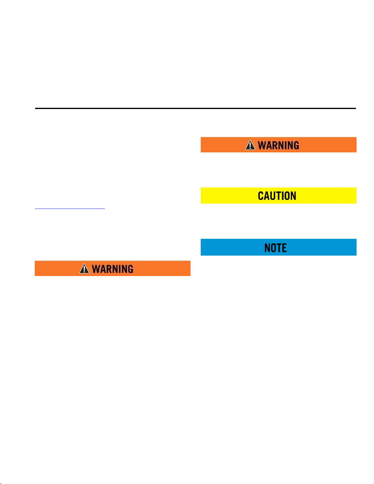
WARNING, CAUTION AND NOTES
The following definitions are found throughout the
manual and apply as follows:
Operating procedures and techniques, which could
result in personal injury and/or loss of life if not
carefully followed.
Operating procedures and techniques, which could
result in damage to equipment if not carefully
followed.
Operating procedures and techniques that are
considered essential to emphasize.
Due to the nature of these processes, ensure that all
safety information, warnings and instructions are
read and understood before any operation or any
maintenance procedures are performed. Some
procedures take place with heavy components and
at moderate heights, ensure proper safety
procedures are maintained when performing these
actions. Failure to use and maintain proper safety
equipment and procedures will cause injury, death or
damage to equipment.
USE OF SHALL, WILL, SHOULD AND MAY
Shall and Will – Used when application of a
procedure is mandatory.
Should – Used when application of a procedure is
recommended.
May - Used to indicate an acceptable or suggested
means of accomplishment.
1-1
Page 5
MSC/MST-OPS-1
31 Dec 2013
SECTION 1
Definitions and Abbreviations
SAFETY MESSAGES
There are several specific safety messages on this
machine. The exact location of the hazards and
description of the hazards are reviewed in this
section. All personnel working on or operating the
machine must become familiarized with all the safety
messages.
Make sure that all of the safety messages are legible.
Clean the safety messages or replace the safety
messages in you cannot read the words. Replace the
illustrations if the illustrations are not legible. When
you clean the safety messages, use a cloth, water and
soap. Do not use solvent, gasoline or other harsh
chemicals to clean the safety messages. Solvents,
gasoline or harsh chemicals could loosen the
adhesive that secures the safety messages. Loose
adhesive will allow the safety messages to detach.
Replace any safety message that is damaged or
missing. If a safety message is attached to a part that
is replaced, install a new safety message on the
replacement part.
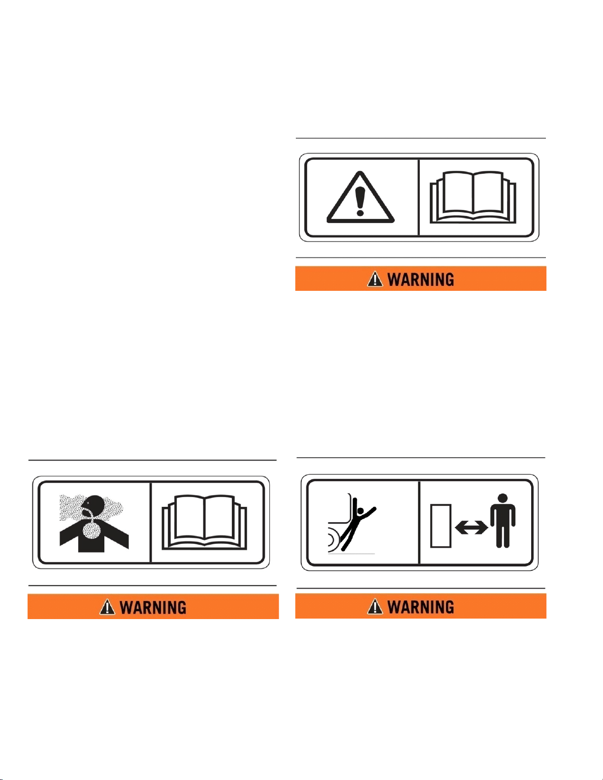
DO NOT OPERATE (2)
This safety label is located on the outside of the front
and rear control boxes (if equipped).
Do not open this control box unless you read and
understand the instructions and warnings in the
Operator and Maintenance Manual. Failure to
follow instructions or heed the warnings could
result in serious injury or death.
TOXI C GAS HA Z ARD (1 )
This safety label is located on the side of the tank and
at all water fill entrances.
Cutting or welding operation on the inside of the
tank can cause the accumulation of toxic gases.
Read and understand instructions and warnings
in the Maintenance Manual. Failure to provide
proper ventilation or breathing apparatus while
conducting these operations may result in serious
injury or death.
BACKING RUNOVER HAZARD (3)
This safety label is located on the rear of the tank and
inside the cab.
The vehicle is equipped with a back-up alarm.
Alarm must sound when operating this vehicle in
reverse. Failure to maintain a clear view in the
direction of travel could result in serious injury or
death.
1-2
Page 6
SECTION 1
Definitions and Abbreviations
MSC/MST-OPS-1
31 Dec 2013
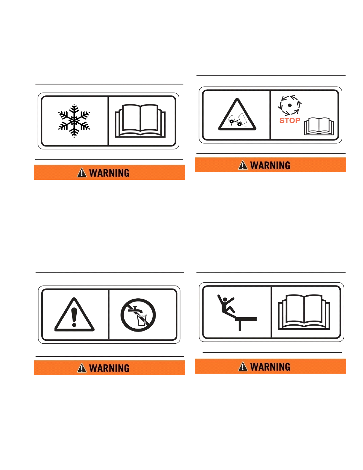
FREEZING (4)
This safety label is located on the side of the tank, at
the sump drain, and on the pump.
Drain tank, fill pipe and valve in freezing weather.
Refer to the Operator and Maintenance Manual
for the procedure to follow.
DO NOT HOIST WHILE IN MOTION (6)
This safety label is located inside the cab.
Do not engage hoist cylinders while vehicle is in
motion. Before engaging hoist STOP the vehicle.
Do not engage hoisting cylinders unless you read
and understand the instructions and warnings in
the Operator or Maintenance Manual. Failure to
follow instructions or heed the warnings will
result in injury or death.
NON-POTABLE (5)
This safety label is located on the side of the tank and
sump drain.
Water held within tank is not potable. Do not use
tank for transport of water intended for human or
animal consumption or serious injury or death
may result.
FALL HAZARD (7)
This safety label is located at the top of the front and
rear of the tank.
Do not walk on the top of tank without fall arrest
PPE. Serious injury or death could occur from a
fall.
1-3
Page 7
MSC/MST-OPS-1
31 Dec 2013
SECTION 1
Definitions and Abbreviations
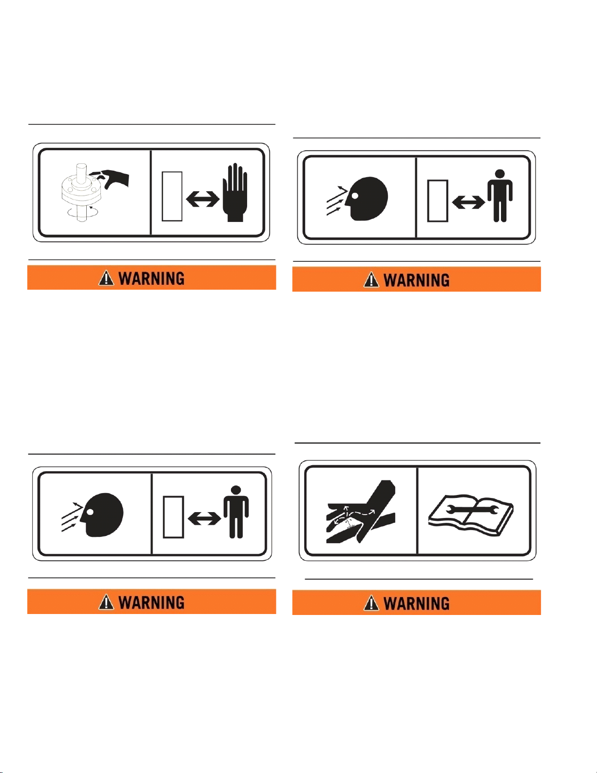
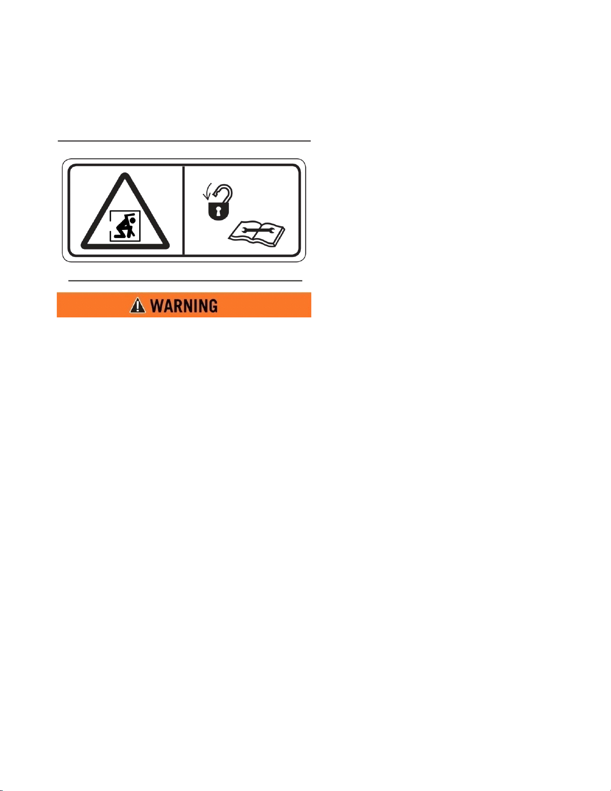
ROTATING SHAFT (8)
This safety label is located on the pump.
Do not place your hand or tools within pump bell
while pump is rotating and/or pressure held
within the motor supply hose. Refer to the
Operator and Maintenance Manual for the
procedures to operate and maintain the pump.
Failure to follow proper procedures could result in
serious injury.
HIGH PRESSURE WATER CANNON (10)
This safety label is located on top of the cab control
box.
Do not operate the water cannon until all
personnel are a safe distance away from the
vehicle.
HIGH PRESSURE SPRAY HEADS (9)
This safety label is located on the spray bar.
Do not operate spray heads until all personnel are
a safe distance away from the vehicle.
HIGH PRESSURE MOTOR (11)
This safety label is located on the hydraulic motor.
Hydraulic motor and supply lines contain oil
under high pressure. Improper removal and
repair procedures could cause severe injury. To
remove or repair, instructions in the Maintenance
Manual must be followed.
1-4
Page 8
SECTION 1
Definitions and Abbreviations
MSC/MST-OPS-1
31 Dec 2013
CONFINED SPACE (12)
This safety label is located near the water tank access
and fill ports.
Do not enter confined spaces without following
established site specific procedures. Failure to
follow proper safety procedures will result in
serious injury or death.
ABBREVIATIONS
BFV - Butterfly Valve
cc - Cubic Centimeters
CCW - Counter Clockwise
CW - Clockwise
fl. oz. - Fluid Ounce
FT - Feet
FPM - Feet Per Minute
GPM - Gallons Per Minute
IN/SQ FT - inches per Square Feet
KM-H - Kilometers Per Hour
Kg - kilograms
Kpa - Kilopascals
l - liters
lpm - Liters per minute
LT - Left as viewed from the operators
position facing forward
m - meters
MPH - Miles Per Hour
MSC/MST - Mega Scraper Conversion
Nm - Newton meters of torque
psi - pounds per square inch
RPM - Revolutions Per Minute
RT - Right as viewed from the operators
position facing forward
SQ FT - Square Feet
VDC - Volts, Direct Current
1-5
Page 9
MSC/MST-OPS-1
4
1
2
3
7
1
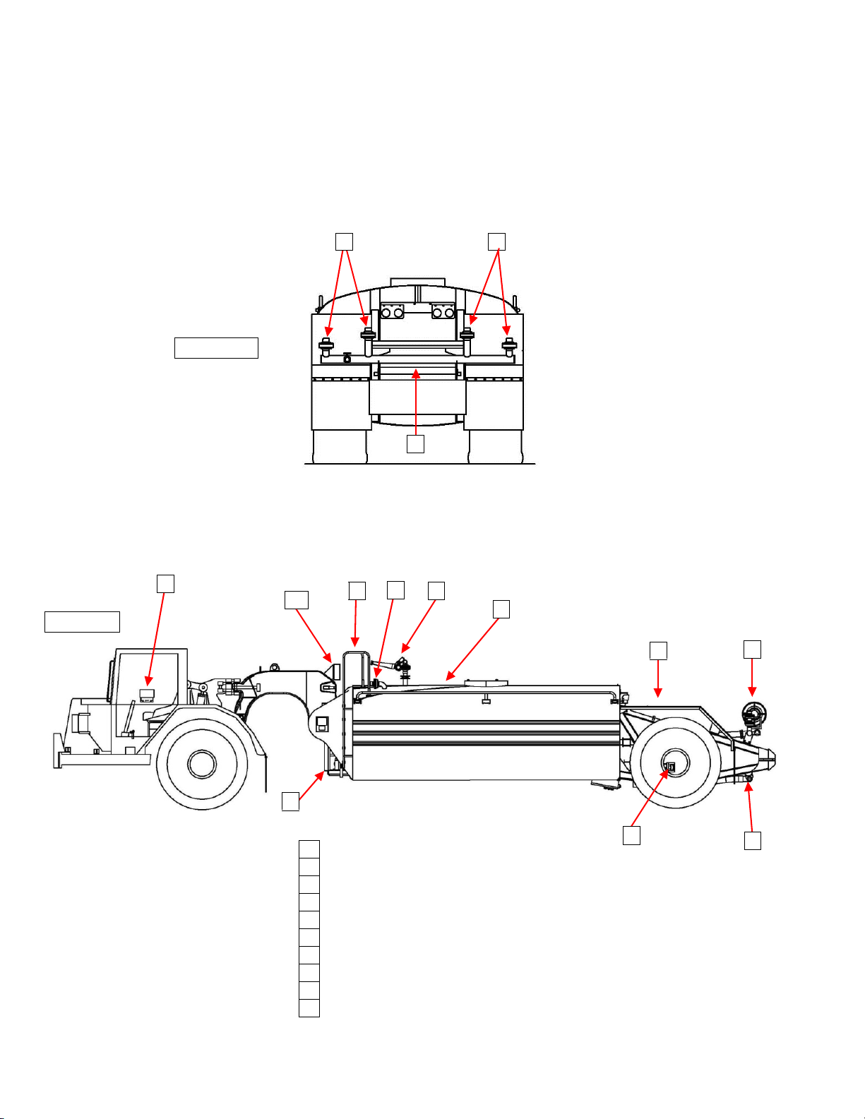
WATER PUMP & HYDRAULIC MOTOR
2
DUMP BAR
3
SPRAY HEADS
4
CAB CONTROLS
5
SUCTION PUMP STATION
6
HAND RAIL & WALKWAY
7
FOAM CONCENTRATE TANK
8
HOSE REEL
9
WATER CANNON
10
SOLENOID BOX
REAR VIEW
SIDE VIEW
9
3
6
10
6
8
3
5
1
31 Dec 2013
SECTION 1
Definitions and Abbreviations
MSC/MST GENERAL OVERVIEW (TYPICAL)
1-6
Page 10
SECTION 2
6
1
7
3
4
5
2
System Description
Contents
MSC/MST-OPS-1
31 Dec 2013
Water Tank (MSC/MST) ..................................................2-1
Water Pump........................................................................2-1
Hydraulic Drive Motor....................................................2-2
Cab Controls (Analog) ....................................................2-3
Cab Controls (Digital)......................................................2-5
Ground Speed Sensing (GPS) Control ......................2-9
Water Cannon System ....................................................2-11
WATER TANK (MSC/MST)
The MEGA steel water tank consists of a water tunnel,
primary floor, vertical baffles, bulkheads, outer skins,
internal piping and external piping. The tank design
is patented and known as the MEGA Anti-surge
Stabilization Tube (MAST).
The MAST is the backbone of the structure and
provides mounting for transverse baffles. The baffles
add to tank strength and dampen water surges. The
forward and rear baffles are reinforced with vertical
beams to provide mounting for the gooseneck and
rear axle bogie respectively. External and internal
piping is also used to carry water from the water
pump to spray heads, water cannon, spray bar, hose
reel, dump bar and tank drain.
Spray System.....................................................................2-12
Dump Bar............................................................................2-13
Hose Reel ............................................................................2-13
Tank Drain...........................................................................2-14
Fire Suppression System ...............................................2-14
Suction Loading (If Equipped) ....................................2-14
Braking System.................................................................2-15
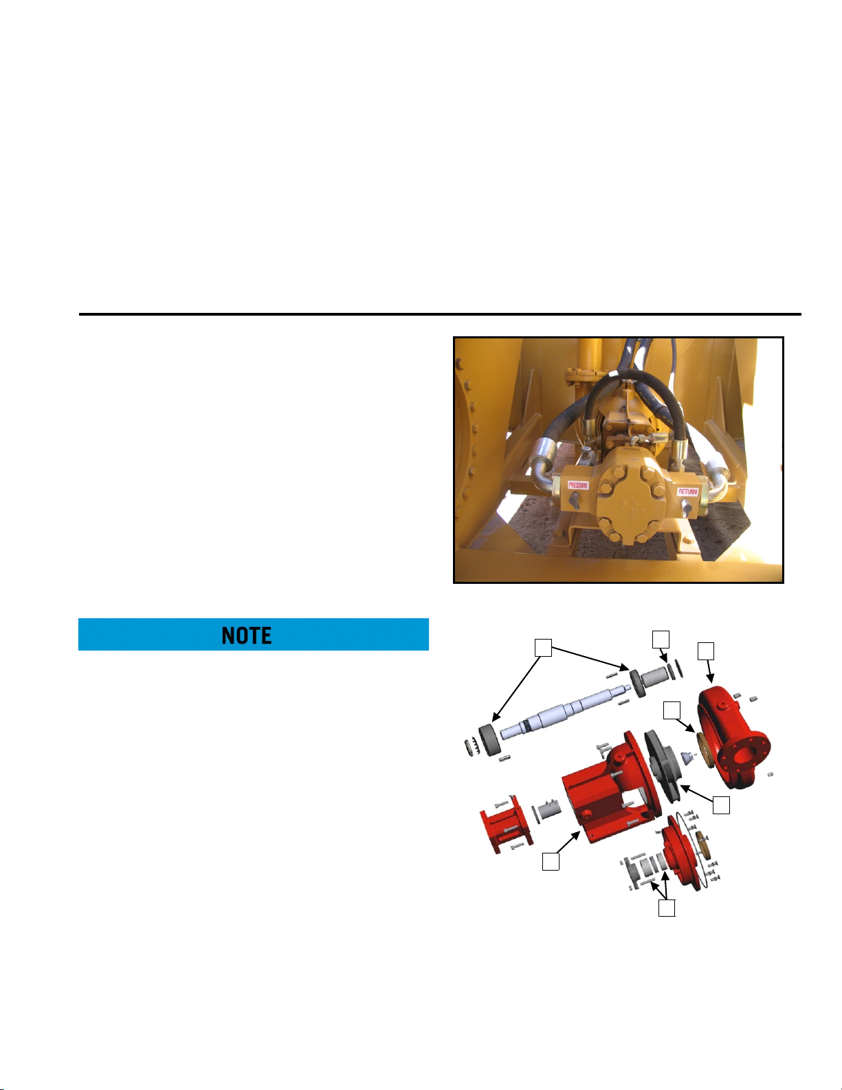
M-4 WATER PUMP
M-4 Water Pump major components and their
functions are:
Early MSC/MST's may have a Berkley water pump
(B4J) installed. Contact MEGA Corp for more
information.
WATER PUMP
MSC/MST units are configured with different types of
water pumps and are based on the size of the water
tank. Typically the 5,000 - 7,000 gallon tanks are
configured with a smaller pump (4 inch inlet & 3 inch
outlet) while the 8,000 - 12,000 gallon tanks are
configured with the larger water pump (6 inch inlet &
4 inch outlet). The water pumps are very similar in
design and for the purposes of this manual the M-4 (6
inch inlet & 4 inch outlet is used to present
component information.
1. Bracket – Main frame of the pump that allows a
pump to be bolted to the tanker and provides the
means to direct mount the hydraulic drive motor.
2. Volute Case – A “snail shell” shaped case that
encloses the impeller. It is narrow at the center
and enlarges from there to the discharge area.
2-1
Page 11
MSC/MST-OPS-1
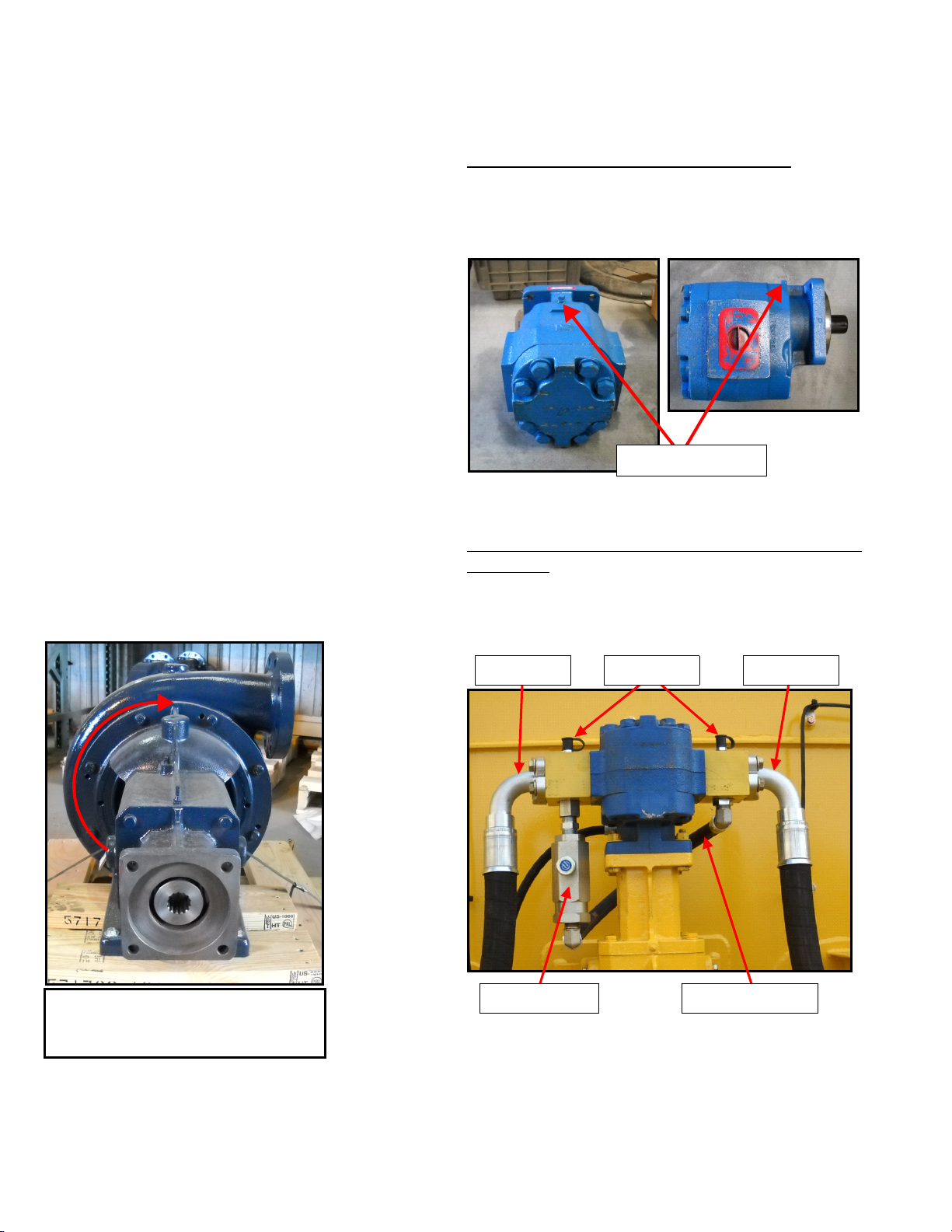
CASE DRAIN PORT
PRESSURE RETURNTEST PORTS
FLOW CONTROL CROSSOVER HOSE
31 Dec 2013
SECTION 2
System Description
3. Wear Ring – Acts as a bearing surface between
the impeller and volute case. Constructed of
bronze material.
4. Impeller – Rotating wheel attached to the shaft
that accelerates the speed of the water producing
water flow and pressure.
5. Shaft Seal – Confines grease to the inner and
outer bearing area while keeping foreign material
from entering the bearing area and seals water
inside the volute case.
6. Rope Seal – Provides a seal around the rotating
pump shaft at the volute case. Constructed of a
graphite rope material that is designed to drip
water and allow shaft lubrication.
7. Upper/Lower Bearings - Provide roller surface
for the pump shaft.
HYDRAULIC DRIVE MOTOR
M-4 PUMP DRIVE MOTOR AND CROSSOVER
ASSEMBLY
The M-4 pump rotates clockwise as viewed from the
drive end of the assembly.
Hydraulic Drive Motor Port Identification
The hydraulic drive motor requires hydraulic flow
from a valve to the motor pressure port, return oil
flow to the hydraulic reservoir and a free to tank case
drain.
Hydraulic Drive Motor Speed Control (Crossover
Assembly)
The hydraulic drive motor speed control (Crossover
Assembly) consists of a flow control valve, 2 hydraulic
manifolds, crossover hose and test ports.
Clockwise rotation as viewed from
the drive end of the water pump
assembly.
The hydraulic drive motor may be installed in 4
different orientations depending on the water pump
location or application.
2-2
Page 12
SECTION 2
ADJUSTING
KNOB
System Description
MSC/MST-OPS-1
31 Dec 2013
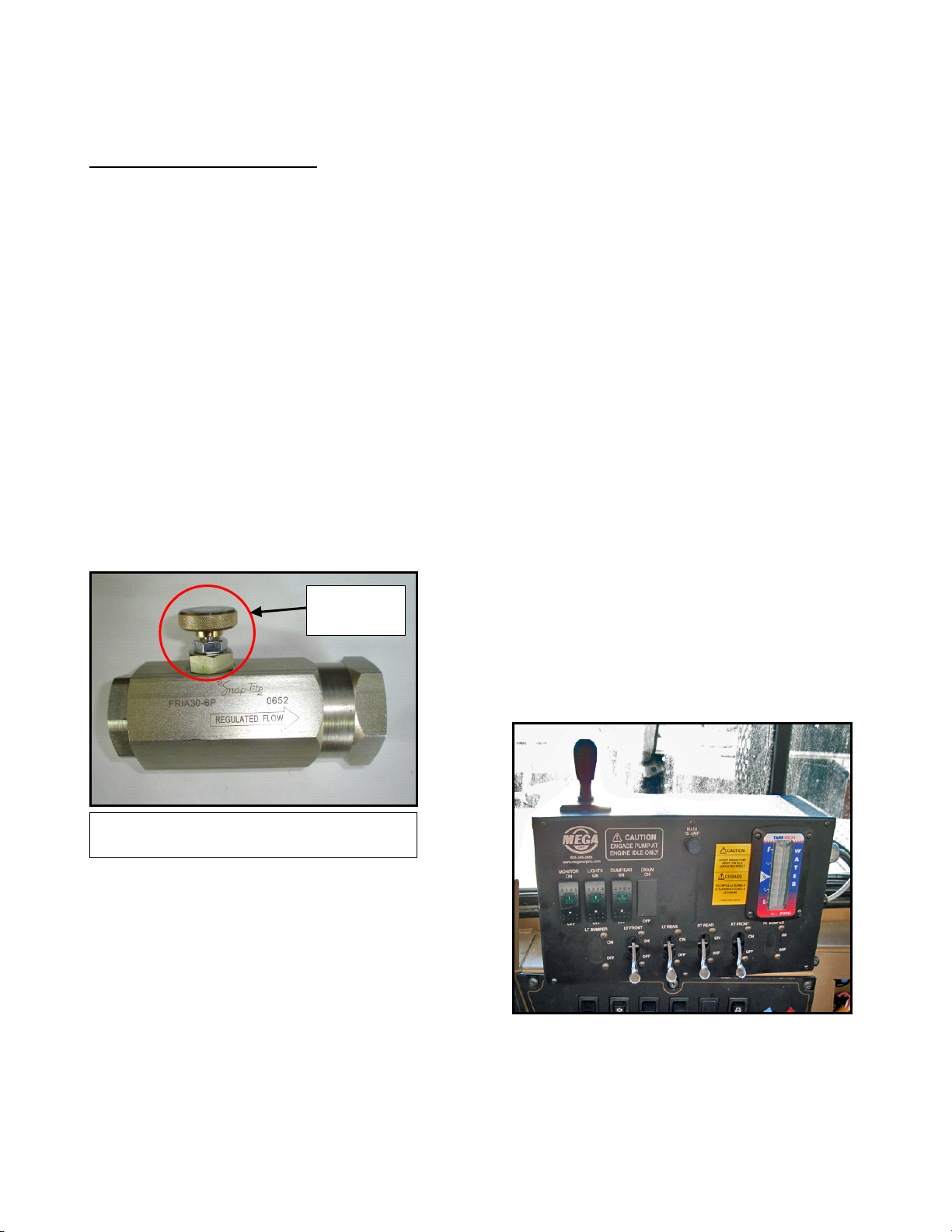
Hydraulic Flow Control Valve
The hydraulic flow control is directional. The arrow on
the body indicates the direction of oil flow to meter
the bypassing oil. The adjusting knob on the valve
will allow adjustment of the oil flow to bypass the
drive motor, up to135 LPM (35 GPM) or up to 700
RPMs (RPM increase/decrease will vary depending on
the size of hydraulic drive motor the unit is equipped
with). If the flow control is reversed, the flow control
adjusting knob will not function and the full flow
capacity of the valve will bypass. This can result in
water pump rpm being below specifications with no
adjustment capability of the adjusting knob. By
turning the adjusting knob clockwise the hydraulic
oil that is bypassing will be reduced, increasing the
speed of the water pump. Turning the knob counterclockwise will increase the volume oil being
bypassed reducing the water pump speed. The flow
control valve is typically mounted on the PRESSURE
manifold of the hydraulic drive motor.
HYDRAULIC DRIVE MOTOR ACTIVATION
The hydraulic drive motor on MSC/MST's are typically
driven by the chassis implement hydraulic system.
The activation can be controlled by the following;
Pilot Operated Diversion Valve - A remote
mounted diversion valve that receives an electric
signal from the cab control pump switch to activate a
pilot control to move a spool within the diversion
valve redirecting the hydraulic oil to flow to the water
pump drive motor. Typically this type of valve is
installed between the hoist pump and the hoist
valve.
Existing Mechanically Operated Implement
Valve - Typically used on early model trucks with a
pneumatic system. This system is operated by the
existing cab control lever. When the lever is moved
to move a spool valve which divert hydraulic oil to
the water pump drive motor.
CAB CONTROLS (ANALOG)
MSC/MST units can be configured with a manual
pneumatic, electro-pneumatic or electro-hydraulic
control system.
Typical 135 lpm (35 gpm) Adjustable
Hydraulic Flow Control
MANUAL PNEUMATIC
Multi-function control box mounted in the cab to
control all water tank functions. Spray system head
and auxiliary functions are controlled by using
manual pneumatic levers, accessory switches and
embedded joystick. The cab control requires 24 VDC
power to operate.
2-3
Page 13
MSC/MST-OPS-1
31 Dec 2013
SECTION 2
System Description
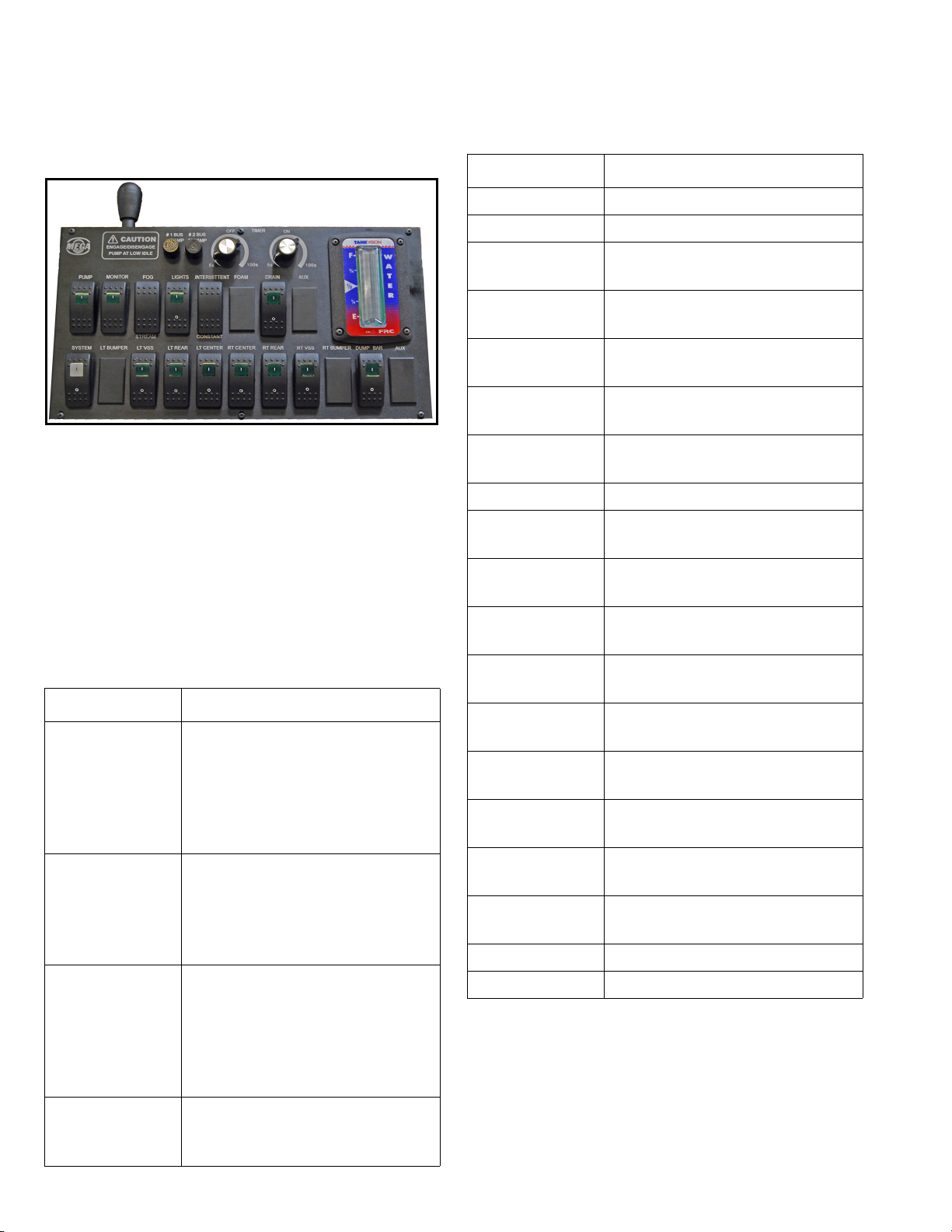
ELECTRO-PNEUMATIC]
Multi-function control box that is mounted in the
vehicle cab to control all water tank functions.
Controls are available for the water cannon,
intermittent spray, water pump, work lights, foam
suppression, adjustable nozzle, system, spray heads,
spray bar, gravity dump bar, and tank drain valve. The
control box also provides indications of tanker water
level and a system fuse holder. The cab controls
requires 24 VDC vehicle power to operate.
The control functions operate as follows:
Control Function
Joystick Sends command signals to the
logic box (electric water cannon)
or hydraulic control valve assembly (hydraulic water cannon) to
move the water cannon left,
right, up and down.
TIMER ON Sets ON time (variable adjust-
ment 5-100 sec) of selected spray
heads and dump bar when the
timer switch is in the intermittent
position
TIMER OFF Sets OFF time (variable adjust-
ment 5-100 sec) between timer
cycles of selected spray heads
and dump bar when the timer
switch is in the intermittent position.
Control Function
MONITOR Opens the water cannon BFV.
LIGHTS Provides power to work lights.
FOAM Open or closes the foam concen-
trate tank in-line control valve.
INTERMITTENT/
CONSTANT
AUX Reserved for specialized func-
ADJUSTABLE
NOZZLE
AUX Reserved for specialized func-
WATER LEVEL Indicates tank water level.
SYSTEM Provides power for all cab control
LT BUMPER Opens or closes left front bumper
LT VSS Opens or closes left vertical side
LT REAR Opens or closes left rear spray
LT CENTER Opens or closes left center rear
RT CENTER Opens or closes right center rear
RT REAR Opens or closes right center rear
RT VSS Opens or closes right vertical side
RT BUMPER Opens or closes right front
DUMP BAR Opens or closes dump bar BFV.
DRAIN Opens or closes tank drain BFV.
Activates or deactivates system
timer function.
tions.
Adjusts water cannon nozzle
from FOG/FAN to STREAM.
tions.
functions.
spray head.
spray head.
head.
spray head.
spray head.
spray head.
spray head.
bumper spray head.
PUMP Routes vehicle hydraulic system
pressure and flow to the water
pump hydraulic drive motor.
2-4
Page 14
SECTION 2
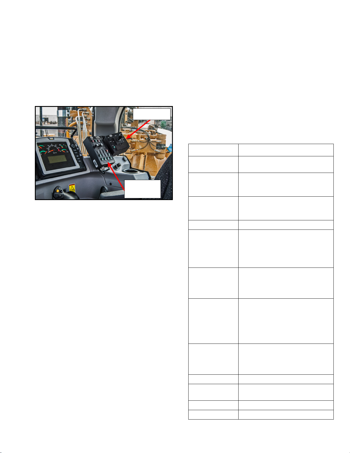
Master
Switch Box
Joystick Box
System Description
MSC/MST-OPS-1
31 Dec 2013
CAB CONTROLS (DIGITAL)
MSC/MST units with fully hydraulic systems MUST be
configured with the Mega Digital Spray Control
System (DiSCS).
ELECTRO-HYDRAULIC SYSTEM (CAT 621H/K only)
This system is designated as a Digital Spray Control
System (DiSCS). The system is comprised of control
boxes, logic controllers, sensors, and cabling. It is a
multi-function control system with a separate
joystick box that is mounted in the vehicle cab. These
two boxes control all water tank functions. The
master switch box operates the water pump, spray
heads, intermittent spray, work lights, hose reel,
dump bar, suction loading, and tank drain valve. The
master switch box also provides indications of tanker
water level and water pump protection features. The
remote mounted joystick box operates the water
cannon, adjustable nozzle and foam suppression. The
cab controls require 12/24 VDC vehicle power to
operate.
ABBREVIATIONS AND DEFINITIONS
AUX1 – Auxiliary or additional optional function
BFV – Butterfly Valve
DMPBAR – Dump bar for heavy spray of water close
to ground. Can be either a gravity or pressure
dump bar (pressure dump bar requires water
pump activation to operate).
DRAIN – Drain (gravity or pressure) for evacuation of
water from tank, mounted typically at the rear
of the tank.
KPH – Kilometers per hour
LT VSS – Left Vertical Side Spray
LTC – Left Center Spray Head
LTR – Left Rear Outer Spray Head
MPH – Mile per hour
RAMP – Ramping Control feature. Rate of increase or
decrease in speed of water flow during PUMP
engagement or disengagement
RT VSS – Right Vertical Side Spray
RTC – Right Center Spray Head
RTR – Right Rear Outer Spray Head
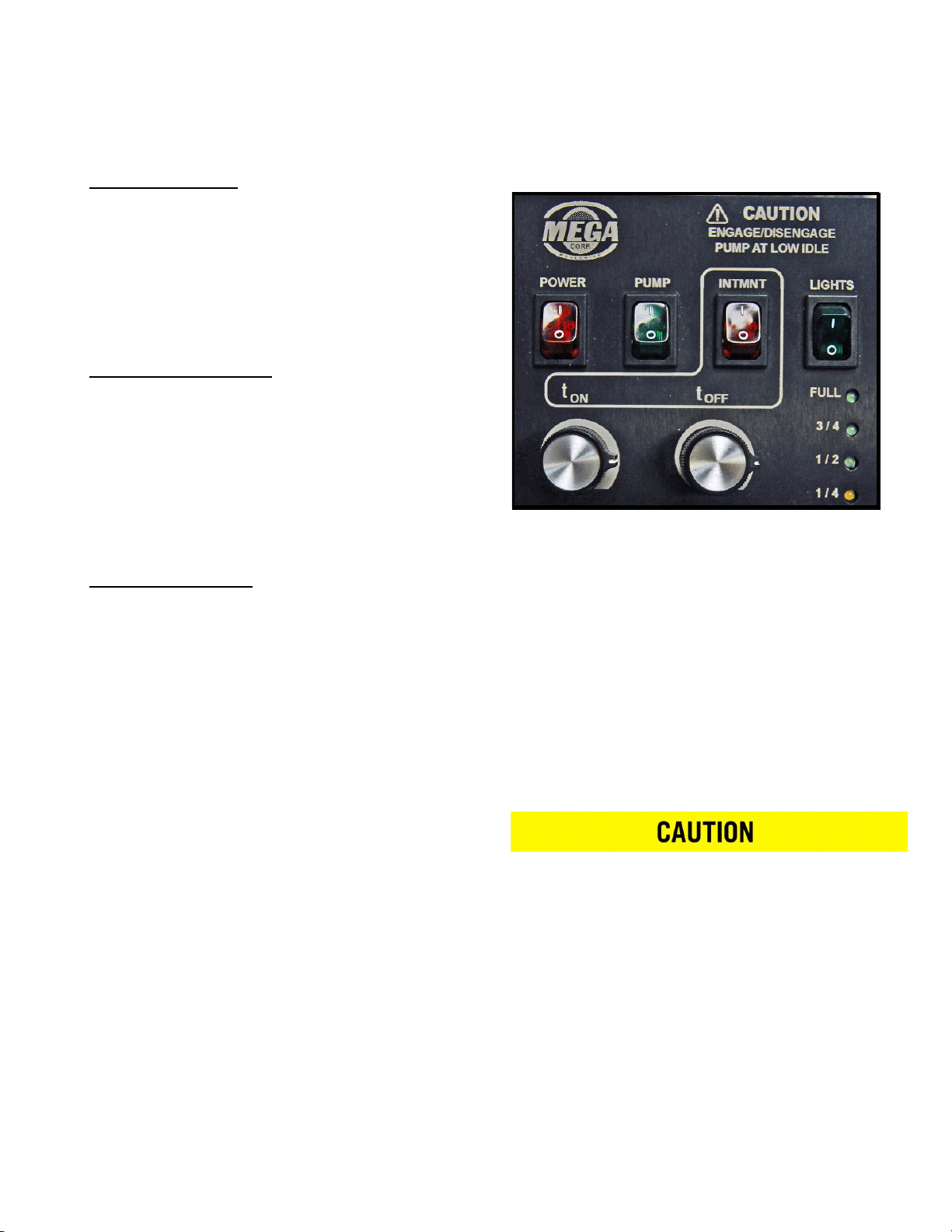
The master switch box control functions operate as
follows:
Control Function
POWER Provides power for all cab control
functions.
PUMP Routes vehicle hydraulic system
pressure and flow to the water pump
hydraulic drive motor.
INTMNT Intermittent setting.
Activates or deactivates system
timer function.
LIGHTS Provides power to work lights.
t ON
(Intermittent
timer—manual
mode)
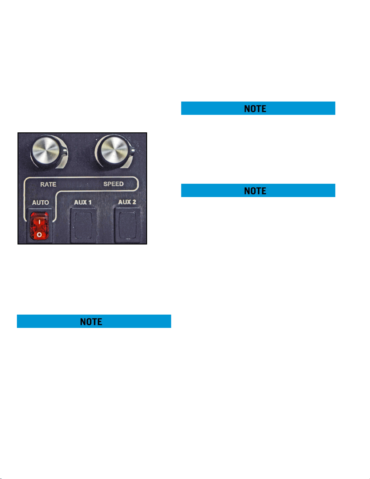
RATE
(GPS Auto Mode)
t OFF
(Intermittent
timer—manual
mode)
SPEED
(GPS Auto Mode)
WATER LEVEL Indicates tank water level.
AUTO Controls activation of GPS Auto
AUX 1 Reserved for user-added option.
AUX 2 Reserved for specialized function.
Sets ON time of selected spray heads
when the timer switch is in the intermittent (INTMNT) position.
Scale: adjustable from 5 seconds to
30 seconds.
Increases or decreases amount of
water dispersed during a cycle when
AUTO switch is on (see extended
description).
Sets OFF time between timer cycles
of selected spray heads when the
timer switch is in the intermittent
(INTMNT) position.
Scale: adjustable from 5 seconds to
30 seconds.
Sets desired ground speed for maximum flow (OPEN continuously) of
selected spray heads (see extended
description).
mode.
2-5
Page 15
MSC/MST-OPS-1
31 Dec 2013
SECTION 2
System Description
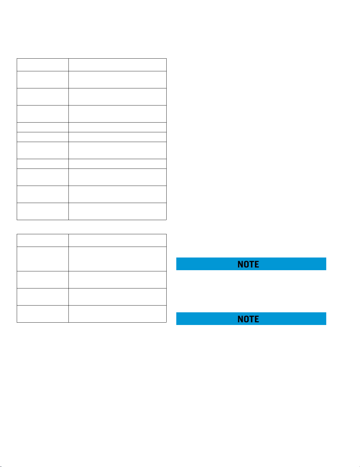
Control Function
HOSE Controls activation of hose reel func-
tion ONLY.
SUCTION LOAD Controls activation of suction load
station ONLY.
LT VSS Opens or closes left vertical side
spray head.
DRAIN Opens or closes tank drain BFV.
DUMP BAR Opens or closes dump bar BFV.
RT VSS Opens or closes right vertical side
spray head.
LT REAR Opens or closes left rear spray head.
LT CENTER Opens or closes left center rear spray
head.
RT CENTER Opens or closes right center rear
spray head.
RT REAR Opens or closes right rear spray
head.
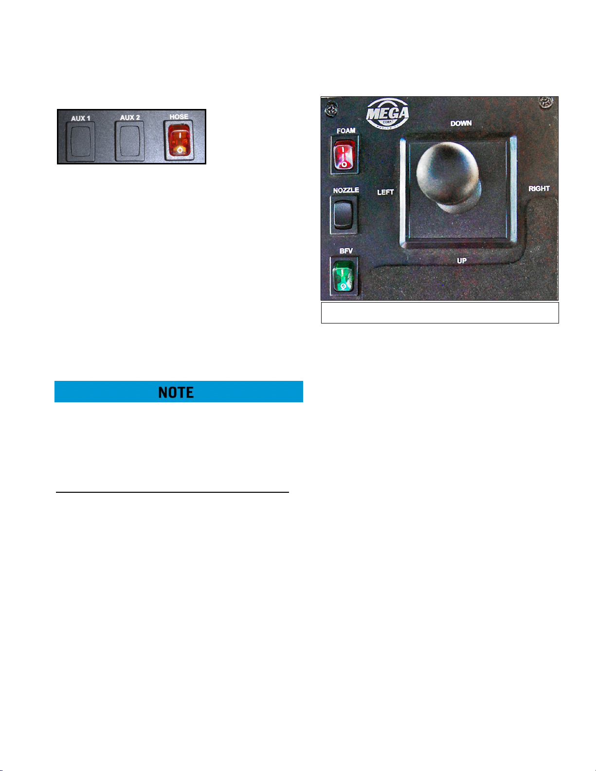
The joystick box functions operate as follows:
Control Function
Joystick
(L EFT-RIGHT-UPDOWN)
FOAM Open or closes the foam concentrate
NOZZLE Adjusts water cannon nozzle from
BFV Opens or closes the water cannon
Sends command signals to the
hydraulic control valve assembly to
move the water cannon.
tank in-line control valve.
FOG to STREAM.
butterfly valve.
Cab control power is then activated by turning the
cab control POWER switch ON while logic controllers
are switched on when the chassis ignition switch is
turned ON.
The spray system will function normally when cab
control power is applied (cab control POWER switch
ON) and sufficient water level (water level EMPTY
light not flashing) is present. Activation of a specific
function is accomplished by depressing the selected
function switch on the master switch box or joystick
box.
Depressing the switch sends a signal to the logic
control panel in the solenoid box to activate a given
function. The logic control then receives the signal
and provides an output command to the given coil or
function.
Once the logic control panel output is processed, the
logic control sends a feedback signal back to the cab
control box to illuminate the LED on the selected
function switch. If the switch LED does not illuminate,
a malfunction may exist in the logic control, wiring
harness or cab control box.
If a function switch is depressed with no
corresponding switch LED, check to ensure system
power switch is ON and the water level empty LED is
not flashing. If the switch LED is not illuminated, a
malfunction may exist.
BASIC SYSTEM THEORY OF OPERATION
Spray system power is provided by chassis 12/24 volt
DC power. Power is routed to cab controllers and
logic control panels by turning on the switched
power via the ignition key switch.
When the chassis ignition switch is turned ON, the
master switch box will undergo a functional self-test.
During this process, ALL LEDs will first turn ON, then
off. While this is occurring, the water level indicator
lights will initially register a FULL tank, and will then
decrease down to EMPTY. The EMPTY light will blink,
and then the water level indicator will count up to
register the current water level of the tank.
If the selected function switch LED illuminates and
the component on the water tanker is not
functioning, the component (water-way valve, spray
head or water cannon) may have malfunctioned.
As functions are turned on and off, the water pump
switch will remain illuminated unless all spray system
functions (water-way valves, spray heads or water
cannon) are turned off. The logic control will
automatically turn the water pump off if all valves are
closed to prevent over-temp of the water pump
volute case. As the water level of the tank drops and
the EMPTY LED begins to flash, the logic controls will
deactivate the water pump to prevent cavitation or
dry running of the water pump.
2-6
Page 16
SECTION 2
System Description
MSC/MST-OPS-1
31 Dec 2013
WATER PUMP PROTECTION FEATURES
Soft Start and Stop
from sudden starts and stops whenever the pump is
turned ON or OFF via the switch or any auto/logic
control feature. This is accomplished by the logic
control system slowly commanding the appropriate
proportional hydraulic control valve to open or close
slowly to prevent hard starts or stops that can reduce
water pump service life.
Low Water Protection
automatically turned off by the logic control system
when a low water condition is detected. The logic
control system monitors tank water level and
commands the water pump to turn off when a
predetermined low water condition is noted. This
prevents the water pump from running in a dry sump
that will over-heat shaft seals due to lack of water.
Continued use will damage the shaft seals.
No-Flow Conditions
automatically turned off after about 100 seconds,
whenever all water discharge valves are closed. The
logic control system monitors all discharge valves
and begins a TIME OUT cycle to turn off the water
pump after about 100 seconds. Any time a discharge
valve is opened during the timing cycle, the clock is
reset. This feature prevents the water from heating
up due to the water pump impeller spinning in a
sump with no flow. The heating of the static water
will also heat the water pump causing deterioration
of grease and premature bearing failure.
– The water pump is protected
– The water pump is
– The water pump is
MASTER SWITCH BOX EXTENDED FUNCTION
DESCRIPTIONS
POWER – Turns POWER ON and OFF to cab controls
and digital controllers.
PUMP – Sends request for pump engagement/
disengagement to the digital control processor. The
digital controllers will activate the hydraulic circuit to
slowly ramp-up or ramp-down the water pump.
The water pump switch will flash whenever the
switch is on and the following conditions apply:
• Low water condition is sensed (EMPTY LED is
flashing).
• No flow condition is sensed (for about 100
seconds, no waterway valves are open)
Engaging/disengaging the water pump above LOW
IDLE will result in water pump component damage
and reduced service life.
INTMNT (Intermittent Function)
Intermittent spray function sends request for
adjustable timing of spray head and dump bar as
commanded by the tON and tOFF dials.
Intermittent will only operate if at least 1 discharge
function (spray head or dump bar) switch is
activated. Water discharge can be stopped at any
time when in INTMNT mode by turning discharge
function switches OFF. The timer will continue to
cycle even if no water is being sprayed
2-7
Page 17

MSC/MST-OPS-1
3s - 15s
min
max
15s - 30s
3 o’clock
3 o’clock
31 Dec 2013
SECTION 2
System Description
The tON and tOFF adjusting knobs command timing
as follows:
• t ON – Adjusts spray head ON time.
• t OFF – Adjusts spray head OFF time.
The relationship between dial rotation and ON/OFF
time is as follows:
– min to 3 o’clock position: 3 sec to 15 sec
– 3 o’clock to max position: 15 sec to 30 sec
The above time ON/OFF scale applies to firmware
versions 3.7.0 and above. For firmware versions 3.6.x
and below, the range is 5 seconds to 30 seconds,
scaled linearly across the rotation of the dial.
The intermittent function will turn selected spray
head or dump bar on and off. Duration of tON and
tOFF cycle times are selected by setting the
appropriate dials on the master switch box. When the
INTMNT switch is ON and functions are selected, the
operator will observe different switch LEDs
conditions to indicate operation within the tON and
tOFF cycles. When a selected function switch (spray
head or dump bar) is operating during an ON cycle,
the selected function switch LED will be illuminated
as well as the INTMNT switch LED. When the INTMNT
cycles automatically to an OFF cycle, INTMNT switch
and function switch LEDs will extinguish. As the ON
cycle is about ready to engage, the INTMNT switch
LED will flash 3 times at the end of the OFF cycle to
indicate the selected spray functions are about to be
turned ON. These light conditions will change back
and forth until intermittent or function switches are
turned off.
Water Level Indicator – Indicates tank water level as
sensed by the water level pressure
sensor in the rear of the water
tank. When the red EMPTY LED
light flashes, the tank is at
minimum water level. This low
level signal is also sent to the logic
control to automatically rampdown the water pump to prevent
component damage. Water pump
operation can only be restored if
sufficient water is in tank to
extinguish the EMPTY light.
In order to re-activate the water pump after lowwater shut-off, first fill the water tank with sufficient
water capacity to permit pump operation. Then turn
the PUMP and POWER switches OFF. Cycle the chassis
ignition key OFF/ON. Wait for the Master Switch Box
to complete its lights check. Then, if the water level
gauge reads above EMPTY, turn the POWER and the
PUMP switches on.
Certain terrains and water level fluctuations may
allow low water protection to capture a low water
level condition, causing the pump ramp-down. If
conditions allow water pump activation after water
level/terrain fluctuations have ceased, then the water
pump may be re-activated by following the steps in
the previous note.
Pressure Discharge Function Descriptions:
Spray Heads – Control opening or closing of the
associated valve when selected, or automatically
controlled when INTMNT function is selected.
Dump Bar (Pressure) – Controls opening or closing
of the BFV when selected, or automatically controlled
when INTMNT function is selected.
Suction Load - Allows continuous hydraulic water
pump drive circuit flow during a low water level
condition. Also disables use of any other master
switch box waterway valve
2-8
Page 18
SECTION 2
Joystick Box Functions
System Description
AUX FUNCTIONS
AUX 1 – Sends request for operation of auxiliary
functions or additional non-standard options of spray
system. This function is unique to a specific tank
serial number.
AUX 2 (Suction Load Station) – If equipped, sends a
request to the hydraulic water pump drive circuit to
allow suction load pump drive motor operation
during a low water level condition while also
disabling the timed-out function. When turned ON,
the AUX2 switch LED will flash rapidly and all
pressure discharge functions are disabled.
HOSE – Allows continuous water pump operation for
hose reel use while also disabling the use of any
other master switch box waterway valves.
Ensure all discharge function switches are OFF when
using HOSE function. Activating the HOSE switch
requests all discharge function to turn OFF (All Spray
heads, Water Cannon BFV, Drain, Dump Bar and
FOAM).
Non-Pressure Discharge Function Descriptions:
Dump Bar (Gravity) – Controls opening and closing
of the BFV when selected, or automatically controlled
when the INTMNT function is selected.
JOYSTICK BOX EXTENDED FUNCTION
DESCRIPTIONS
The joystick box houses logic controls for the joystick
and the FOAM, NOZZLE, and BFV switches. These
switches and the joystick control requests for water
cannon operation.
MSC/MST-OPS-1
31 Dec 2013
BFV – Sends request to open or close butterfly valve.
The butterfly valve controls water flow to the Water
Cannon. Activating the BFV switch requests the water
PUMP to stay ON with NO other pressure discharge
functions activated providing, sufficient water is in
tank to allow command to be sent.
JOYSTICK – Sends requests for rotation and
elevation motion for water cannon operation.
GROUND SPEED SENSING (GPS) CONTROL
The MEGA ground speed sensing control system is an
independent and self-contained GPS unit and
antenna that provides speed information to the
existing Mega Digitally Integrated Spray Control
System (DiSCS). The DiSCS’s logic control uses the
ground speed signal to automatically cycle and pulse
spray heads to obtain a desired lay-down of water
regardless of ground speed. The system contains
controls to adjust maximum water discharge speed
as well as actual rate of flow. This automatic control
reduces water usage and prevents over-watering of
haul roads and intersections.
FOAM – Sends request for FOAM agent valve to open
or close.
NOZZLE – Sends request for adjustable nozzle on
water cannon to move from FAN/FOG to STREAM
spray patterns.
The system will automatically close all discharge
functions (spray heads) below 5 KPH/3 MPH to
prevent puddling of water at intersections. The
system also opens selected discharge functions
when accelerating above 5KPH/3 MPH.
2-9
Page 19
MSC/MST-OPS-1
31 Dec 2013
SECTION 2
System Description
The system warns the operator of all malfunctioning
system functions and provides full manual control of
all spray system functions in the event of an AUTO
mode failure. All automatic system protection
features of low water level conditions, no-flow
conditions and water pump soft start/stop feature
still operate normally in the AUTO mode.
GPS EXTENDED FUNCTION DESCRIPTIONS
SPEED – Above what vehicle speed the command is
sent for maximum flow of all selected discharge
functions (spray heads). Below this vehicle speed,
timed cycles and/or reduced water volume flow
occur.
The scale for the SPEED function is 0 KPH/0 MPH (Full
LEFT) to 48 KPH/30 MPH (Full RIGHT).
When vehicle speed goes below the set SPEED,
application rate of water discharged will be either
pulse the requested discharge functions and/or
reducing the number of discharge functions based
on the RATE selected.
IF vehicle speed is GREATER than set SPEED the RATE
has little or no effect on water discharge. Typically all
requested pressure discharge functions are ON and
no timing cycle.
AUTO – This function has priority over intermittent
mode. The intermittent light will illuminate steadily
when operating conditions are met and AUTO is ON.
AUTO enables vehicle speed signal from the GPS
module to activate the speed sensing mode, and
operates the spray system based on RATE and SPEED
adjustments. Pulse will begin when the AUTO
function requests reduced volume.
Near or below 4.8 KPH/3 MPH, AUTO will switch to
INTERMITTENT mode and discharge functions may
operate continuously or ramp down the water pump
to OFF. When vehicle speed rises above 4.8 KPH/3
MPH, AUTO will resume control of the system.
RATE – Is the distance traveled/time for spray head
ON cycle.
•Knob turned counterclockwise reduces ON
distance/ ON time
• Knob turned clockwise increases ON distance/
ON time
Reduced Volume Mode – Reduction in discharge
volume by reducing the number of spray heads
requested to activate.
• If 4 rear spray heads are requested, reduced
volume allows only the 2 outer spray heads to
turn ON and the 2 center spray heads are OFF.
• If 3 rear spray heads are requested 1 spray head
will be OFF, typically the center head adjacent to
the outer head requested.
• If 2 spray heads are requested 1 spray head will
be OFF typically the center spray head unless no
center spray heads are requested, then NO spray
heads will be OFF.
Pulsing – Reference to Pulse Width Modulation or
ON/OFF cycle.
2-10
Page 20

SECTION 2
System Description
MSC/MST-OPS-1
31 Dec 2013
WATER CANNON SYSTEM
The system is comprised of a water cannon (hydraulic
or electric), hydraulic control valve assembly or logic
box, butterfly valve assembly, nozzle and controls.
WATER CANNON (Hydraulic)
cannon is threaded to a flanged pipe that mounts
directly above the BFV. The water cannon also
provides mounting for a variety of different nozzles.
HYDRAULIC CONTROL VALVE ASSEMBLY
the cab control box. A pressure relief valve is
incorporated in the manifold block to protect the
water cannon system against any over pressurization
conditions. The assembly is mounted to the tank
lower flange and receives hydraulic pressure from the
vehicle hydraulic pump.
A metal waterway that directs
a stream of water in both
elevation (up-down) and
rotation (right-left). Hydraulic
motors move the waterway
based upon hydraulic flow
from the hydraulic control
valve assembly as
commanded by the cab
control joystick. The water
The assembly contains three
hydraulic solenoid valves that
direct hydraulic pressure to
the hydraulic motors on the
water cannon and BFV
cylinder as commanded by
WATER CANNON (ELECTRIC)
A metal waterway that directs a
stream of water in both
elevation (up-down) and
rotation (right-left). 24 VDC
electric motors move the
waterway based upon filtered
electronic signals from the logic
box as commanded by the cab
control joystick. The water
cannon is threaded to a flanged pipe that mounts
directly above the BFV. The water cannon also
provides mounting for a variety of different nozzles.
ELECTRO-PNEUMATIC BFV ASSEMBLY
An electro-pneumatic valve that
controls the flow of water to the
water cannon. A 24 volt DC
solenoid receives commands
from a cab control MONITOR /
BFV switch through the logic
box to route pressurized air to
an air chamber which opens or closes a 3” valve. The
assembly is clamped between upper and lower pipe
flanges.
WATER CANNON NOZZLES AND STREAM SHAPERS
Smooth Bore Nozzle
A cone shaped 1.5” diameter nozzle
that directs water flow. The nozzle
has a built in stream shaper that
smooths water flow to increase water
stream distance.
HYDRAULIC BFV ASSEMBLY ASSEMBLY
A hydraulically operated
valve that opens or closes
to control water flow to
the water cannon. The
hydraulic cylinder receives
hydraulic pressure from
the hydraulic control valve
or solenoid control box assembly as commanded by
the cab control water cannon switch. The assembly is
clamped between upper and lower pipe flanges.
Smooth Bore (Stackable)
A segmented cone shaped nozzle
that directs water flow. The nozzle
opening is adjusted by removing
segments to acquire the most
efficient nozzle opening for a given
water pump operating pressure.
Nozzle segment diameters are 1?”,
1½”, 1¾” and 2”. The nozzle requires
and in-line stream shaper to increase
water stream distance.
2-11
Page 21

MSC/MST-OPS-1
31 Dec 2013
SECTION 2
System Description
In-Line Stream Shaper
A performance enhancer that is
mounted between the water
cannon outlet and the selected
straight bore nozzle. The stream
shaper pathway is a honeycomb
style channel designed to
efficiently shape a water stream
to maximum water stream
distance.
Manual Adjustable Nozzle
Fog/Stream:
allows the operator to manually adjust selected
water stream patterns from fog to stream. Some
nozzles are configured for fire suppression foam
eduction.
Fan/Stream:
allows the operator to manually adjust selected
water stream patterns from flat fan to stream. The flat
fan pattern orientation is adjustable from horizontal
to vertical by reorienting the nozzle on the water
cannon.
Remote Adjustable Nozzle (Electric/Hydraulic)
A modified straight bore nozzle that
A modified straight bore nozzle that
Fan/Stream
A modified straight bore nozzle that allows the
operator to remotely adjust selected water stream
patters from flat fan to stream from the cab control.
The nozzle inner or outer barrel is moved by an
electric actuator to obtain the fan or stream pattern.
The flat fan pattern orientation is adjustable from
horizontal to vertical by reorienting the nozzle on the
water cannon.
SPRAY SYSTEM
The spray head system consists of 4, 6 or 8 hydraulic
or pneumatic actuated spray heads, cab controls,
solenoid control box assembly, and hydraulic or
pneumatic hosing.
PNEUMATIC SPRAY HEAD
A two piece aluminum valve
body and adjustable ring
mounted to a water supply
header pipe. The upper
portion of the valve body is
an air chamber with a
diaphragm and guide disk
assembly attached to the bottom. The air chamber
receives pressurized air from the solenoid control box
as commanded by the cab control switch. When the
upper portion of the valve body is pressurized the
guide disk will seal the opening on the lower portion
of the valve and stop water flow.
A modified straight bore nozzle that allows the
operator to remotely adjust selected water stream
patterns from fog to stream from the cab control. The
nozzle inner or outer barrel is moved by an electric or
hydraulic actuator to obtain the fog or stream
pattern. Some nozzles are configured for fire
suppression foam eduction.
When the cab control system is OFF and the water
pump is OFF the air chamber incorporates a spring
that will apply pressure to the guide disk assembly
and seal the opening on the lower portion of the
valve and stop flow. When air pressure is removed
from the upper portion of the valve body when the
water pump is ON and the cab control switch ON,
pressurized water from the header pipe will unseat
the guide disk and water will flow from the lower
portion of valve.
2-12
Page 22

SECTION 2
1/4” Opening
3/8” Opening
Pneumatic
Hydraulic
System Description
MSC/MST-OPS-1
31 Dec 2013
HYDRAULIC SPRAY HEAD
A two piece aluminum valve
body, hydraulic cylinder and
adjustable ring mounted to a
water supply header pipe. The
upper portion of the valve body
contains a hydraulic cylinder
that receives hydraulic pressure
from the system solenoid control box as commanded
by the cab control switch. When the hydraulic
cylinder on the upper portion of the valve body is
pressurized the cylinder extends to contact the guide
disk and seal the opening on the lower portion of the
valve and stop water flow. When the cab control
system is OFF and the water pump is OFF the upper
valve body incorporates a spring to apply pressure to
the guide disk to seal the opening on the lower
portion of the valve and stop flow. When the spray
head switch is turned on hydraulic pressure retracts
the hydraulic cylinder and pressurized water from the
header pipe will unseat the guide disk and water will
flow from the lower portion of valve.
SOLENOID CONTROL BOX
The control box assembly is mounted to the forward
bulkhead or the rear of the gooseneck of the MSC/
MST. The assembly contains pneumatic or hydraulic
solenoid valves that direct pneumatic or hydraulic
pressure to the spray head as commanded by the cab
control box. The solenoids receive pneumatic
pressure from the vehicle or hydraulic pressure from
water pump oil circuit and 24 VDC power from the
cab control box.
DUMP BAR
Spray Head Adjustable Rings
The adjustable ring is used to control fan width and
water flow. The ring may be loosened and rotated to
expose more or less of the lower valve opening to
control water fan width from 15° to 90°. The ring also
may be used rotated to a 1/4” or 3/8” slot (as shown
below) to increase or decrease overall water flow. The
greater the opening, the greater the water flow.
A spray bar that contains several rows of 3/8” drain
holes to dispense water. A hydraulically operated BFV
controls the water supply to the dump bar. The BFV is
controlled electrically from the cab control box and is
actuated by a hydraulic cylinder. The actuators
receive hydraulic pressure from the solenoid control
box assembly. Dump bars can be either gravity or
pressure fed.
HOSE REEL
A reel assembly that is
located on the bottom aft
end of the water tank fitted
with a 1” or 1.5” diameter
reinforced rubber hose and
a fire fighting style nozzle.
The hose reel assembly
receives pressurized water
from the pressurized
manifold on the back of the tank to operate.
2-13
Page 23

MSC/MST-OPS-1
31 Dec 2013
SECTION 2
System Description
TANK DRAIN
A hydraulic BFV attached to the water tank pressure
pipe is used to drain water from the water tank. The
BFV is controlled electrically from the cab control box
and is actuated by a hydraulic actuator. The actuators
receive hydraulic pressure from the solenoid control
box assembly. Tank drains can be either gravity or
pressure fed.
FIRE SUPPRESSION SYSTEM
A system that consists of a 120 or 60 gallon stainless
steel holding tank, an electric or pneumatic actuated
shut-off valve, in-cab control switch, hosing and a
foam eduction nozzle mounted to the water cannon.
FOAM EDUCTION NOZZLE
A manual or remote
adjustable (fog/stream)
nozzle is attached to the
water cannon waterway. The
nozzle inner housing uses
high pressure water to create
a venture effect that will
create a suction force,
pulling foam concentrate from the holding tank.
Once foam concentrate is flowing, the nozzle
proportions foam concentrate, water and air to
produce finished foam. The nozzle can be adjusted to
allow control of foam solution at a rate of 1%, 3% or
6%. Rate adjustment is obtained by replacing a
removable disk.
SUCTION LOADING (IF EQUIPPED)
FOAM CONCENTRATE TANK
A stainless steel tank
mounted in the forward
upper portion of the water
tank. The holding tank
contains a supply tube that
extends to the bottom of the
tank and connected to a
flexible hose at the top of the tank and then routed to
the foam agent shut-off valve. The tank also contains
a pressure/vacuum cap which keeps foreign matter
out of the tank while providing for pressure relief and
air displacement during temperature changes.
ELECTRIC/PNEUMATIC SHUT-OFF VALVE
The in-line shut-off valve is mounted on the foam
tank upper lip and is controlled by the in-cab control
FOAM switch. The shut-off valve is actuated by either
an electric or pneumatic actuator that is controlled
by the in-cab control switch. Once the shut-off valve
is opened, foam concentrate will flow from the
holding tank to the water cannon nozzle if the water
cannon and water pump switches are ON.
A second water pump mounted typically to the water
pump sump at the rear of the MAC. The suction
loading station is equipped with a manual diversion
valve that will switch the hydraulic oil flow from the
main discharge pump drive motor to the suction
loading pump drive motor. When oil is diverted to
the suction loading drive motor, it can pull water
from a holding pond and fill the MAC. The suction
loading option includes lengths of 4” suction hose
equipped with quick couplers and a check valve inlet
foot with a debris screen. The suction hoses are
typically stored in tubes either built into the MAC or a
hanging tube arrangement.
2-14
Page 24

SECTION 2
System Description
MSC/MST-OPS-1
31 Dec 2013
BRAKING SYSTEM
MSC/MST PRIME MOVERS
See the prime mover Operator and Service Manual
for brake system information.
MSC/MST 611/615
See the CAT 611/615 Operator and Service Manual
for brake system information.
MSC/MST 613
See the CAT 613 Operator and Service Manual for
braking system information
MSC/MST 621H/K
See the CAT 621H/K Operator and Service Manual for
braking system information.
For further information contact MEGA Corp. Product
Support Group at:
US toll free: 1-800-345-8889
Direct: 1-505-345-2661 or visit our website at
www.megacorpinc.com for more detailed contact
information.
AIR TANKS
The MSC/MST is equipped with two 8 inch x 32 inch
air cylinder mounted to the MSC/MST rear bogie that
store 110-130 psi air. The cylinders receive
pressurized air from the tractor primary air tank
mounted under the tractor cab.
TANK PRESSURE SENDING UNIT
A 24 VDC pressure sending unit is mounted to the
rear MSC/MST air tank and is wired into existing
tractor brake pressure indicating and warning
systems. The sending unit provides air pressure
sensing for the tractor air pressure gauge mounted in
the dash. The sending unit also provides a signal to
the brake low pressure warning system that sounds
an audible warning tone when brake supply pressure
drops below allowable limits.
MSC/MST 621G & 631G
The MSC/MST rear brake system is integrated with
the existing tractor parking, service and emergency
brakes. All three systems are activated with the
existing brake controls located in the tractor cab. See
the CAT 621G and 631G operator and service manual
for additional tractor brake information.
The MSC/MST rear brake system consists of a wheel
group, two additionally air tanks, pneumatic
manifold assembly, pneumatic brake relay valve,
brake pods, solenoid valve, pressure switch, pressure
sending unit and hosing.
PNEUMATIC MANIFOLD ASSEMBLY
A pneumatic
manifold mounted
in the rear bogie
used to route air
pressure for service,
parking and
emergency brake
operation. The
manifold also
provides mounting for a check valve, parking brake/
emergency solenoid valve and parking brake
pressure switch.
CHECK VALVES
A spring operated valve allowing air flow in a
predetermined direction. A one-way check valve is
located at the MSC/MST rear air tank tractor air
supply in. A double-check valve is located on the
pneumatic manifold.
2-15
Page 25

MSC/MST-OPS-1
31 Dec 2013
SECTION 2
System Description
PARKING /EMERGENCY BRAKE SOLENOID
brake pods. This release of air pressure will cause the
parking/emergency brakes to be applied.
PARKING BRAKE PRESSURE SWITCH
A 24 VDC electrical solenoid that
opens or closes to control the
parking or emergency brake
function. The solenoid valve
responds to electrical signals as
commanded by the parking or
emergency brake in the tractor
cab. The solenoid valve will open to
bleed off parking/emergency
brake release pressure from the
A 24 VDC pressure switch used
to illuminate the parking brake
warning light in the tractor cab.
The sensor will turn on the
parking brake warning light
when parking brake release
pressure drops below allowable
limits.
BRAKE PODS
A pneumatic cylinder designed to extend or retract
and apply service, parking or emergency brakes. The
pods are mounted to the MSC/MST rear bogie and
are connected to the wheel group brake activation
lever. The pod contains a coil spring and responds to
pressure received from the brake relay valve as
commanded by service brake pedal. The pod will also
apply parking or emergency brakes when one side of
the cylinder is depressurized when commanded by
the activation of the parking or emergency brakes.
Lose of pneumatic pressure allows the brake pod coil
spring to extend the rod end.
SERVICE BRAKE RELAY VALVE
generated by activating the service brake pedal
located in the tractor cab.
A pneumatic relay that
controls and routes air
tank activation pressure
to both brake pods. The
relay controls air
pressure applied to the
brake pods as
commanded by a
pneumatic signal
THEORY OF OPERATION
Parking Brake
The parking brake is applied by activating the
parking brake switch in the tractor cab. Once the
switch is moved to the park position an electrical
signal is sent to the parking brake solenoid valve
mounted on the rear bogie pneumatic manifold.
The sent signal will open the solenoid valve allowing
pneumatic pressure to decrease from one side of the
brake pod. The brake pod coil spring can now
overcome air pressure and extend the brake pod rod
end attached to the wheel group brake lever and
apply the brakes. Once parking brake pneumatic
pressure drops below allowable limits, the parking
brake pressure switch mounted on the pneumatic
manifold will close and illuminate the parking brake
warning light in the cab of the tractor.
The parking brake is released by activating the
parking brake switch. Once the switch is moved an
electric signal is sent to close the parking brake
solenoid valve. The valve closing will allow
2-16
Page 26

SECTION 2
System Description
pneumatic pressure from the pneumatic manifold to
be routed to the brake pod. This pressure increase
will eventually overcome the brake pod coil spring
and retract the brake pod cylinder rod end attached
to the brake pod releasing the brakes. As pressure
increases above allowable limits, the parking brake
pressure switch will turn off the parking brake
warning light in the tractor cab once pressure is
above allowable limits.
Service Brake
The service brake is applied by pressing down on the
service brake pedal in the tractor cab. Pressing down
on the pedal will send a pneumatic pressure signal to
the service brake relay valve mounted on the rear
bogie. The sent signal will release pneumatic
pressure from the brake pod chamber allowing the
pod coil spring to extend the rod end and apply
service brakes.
MSC/MST-OPS-1
31 Dec 2013
The service brake is released by releasing the brake
pedal. Once the pedal released a pneumatic signal is
received by the brake relay to increase air pressure to
the brake pod. As pneumatic pressure increases the
force of the brake pod coil spring is overcome and
the service brake is released.
Emergency Brake
The emergency brake theory of operation is the same
as the parking brake except for the means of
activation. Activation is accomplished by using the
emergency brake foot switch located on the floor of
the tractor cab just left of the service brake pedal.
2-17
Page 27

MSC/MST-OPS-1
31 Dec 2013
SECTION 2
System Description
2-18 (Blank)
Page 28

SECTION 3
Limitations
Contents
Water Pump.......................................................................3-1
WATER PUMP
The following cautions are operational limitations of
Mega water pumps. Failure to heed these cautions
may result in reduced pump life and severe water
pump damage.
MSC/MST-OPS-1
31 Dec 2013
Water pump RPM must not exceed the specifications
listed below with engine at HIGH IDLE. Failure to
ensure water pump speed is at or below
specifications will result in reduced spray system
component service life.
Do not operate the water pump in a dry sump.
Operating the water pump with a dry sump will result
in water pump component damage and reduced
service life.
Engaging/disengaging the water pump above LOW
IDLE may result in water pump component damage
and reduced service life.
Limit water pump operation to 2.5 minutes when in a
no-flow condition (not flowing water through spray
heads, dump bar, water cannon, drain valve or hose
reel). Water pump operation in a no flow condition
will cause overheating of the water pump and
damage to the shaft bearings and seals.
PUMP MODEL RPM
M-3 PUMP 2350 ± 50
M-4 PUMP 1,900 ± 50
M-4B PUMP 2,000 ± 50
If water pump RPM is to out of the desired range,
adjust the water pump hydraulic drive motor flow
control valve to obtain specified RPM.
The suction loading pump has a maximum vertical
lift capability of 8-10 feet. Attempting to pump water
into the tank from a reservoir that is more than 8-10
feet below the pump station will result in reduced
suction loading performance.
Avoid any sudden stoppage of water pump e.g.;
disengaging water pump above LOW IDLE. Stopping
water pump suddenly above LOW IDLE will result in
shaft, impeller and drive motor damage.
3-1
Page 29

MSC/MST-OPS-1
31 Dec 2013
SECTION 3
Limitations
3-2 (Blank)
Page 30
SECTION 4
Normal Operations
Contents
MSC/MST-OPS-1
31 Dec 2013
Description.........................................................................4-1
Before Operations............................................................4-1
Operations..........................................................................4-1
DESCRIPTION
This section provides the vehicle operator with step
by step operating procedures for the installed
MSC/MST system. The information is separated into
before operations, operations, and after operations. A
pocket size checklist of all listed procedures is also
provided in the Appendix for use in the vehicle cab.
BEFORE OPERATIONS
These procedures are used to perform a walk-around
inspection of the MEGA water tanker system before
use or the beginning of a shift. This inspection is in
addition to and does not replace the vehicle
manufacturer’s inspection requirements.
1. Chocks – As Required
2. Vehicle Parking Brake – ON
3. Cab Control Switches – SET OFF
4. Bumper Spray Heads – SECURED & SET
5. Vehicle Hydraulic Tank – SERVICED
After Operations...............................................................4-5
Cold Weather Operation And Storage .....................4-5
10. Tank Drain Petcocks – CLOSED
11. Spray Heads – SECURED & SET
12. Water Pump Assembly – CHECKED
a. Water Pump – Check to ensure volute case
drain valve is closed.
b. Water pump and drive motor for evidence of
overheating.
13. Hose Reel – CHECKED
OPERATIONS
Use these procedures to safely operate the standard
and optional systems installed on the MEGA water
tanker.
Limit water pump operation to 2.5 minutes when in a
no-flow condition (not flowing water through spray
heads, dump bar, water cannon, drain valve or hose
reel). Water pump operation in a no flow condition
will cause overheating of the water pump and
damage to the shaft bearings and seals.
6. Gooseneck Lines & Hoses – CHECKED & SECURED
7. Solenoid Control Box – CHECKED AND SECURED
8. Water Cannon – CHECKED & SECURED
a. Nozzle – Check for security and kinking of
foam concentrate supply line.
9. (If Equipped) Foam Concentrate Level –
CHECKED. At least 1” from the top of the foam
tank.
Ensure PPE fall arrest harness is worn, adjusted
properly and attached to an anchor point. Failure
to use PPE properly may result in personnel injury
or death.
SPRAY HEAD SYSTEM
Operating more than 4 spray heads simultaneously
will greatly reduce the width and flow of active spray
heads.
1. Cab Control SYSTEM/POWER Switch – ON
2. INTERMITTENT TIMER – SET
a. TIMER ON/OFF Dials – SET
b. INTERMITTENT Switch – SET
3. PUMP Switch – ON
Engaging/disengaging the water pump above
LOW IDLE may result in water pump component
damage and reduced service life.
4-1
Page 31
MSC/MST-OPS-1
31 Dec 2013
SECTION 4
Normal Operations
4. Individual Spray Heads – SELECTED
Once operations are complete:
5. PUMP Switch – OFF
Engaging/disengaging the water pump above
LOW IDLE may result in water pump component
damage and reduced service life.
6. Cab Control SYSTEM/POWER Switch – OFF
GPS AUTO MODE
1. Cab Control POWER Switch – ON
2. PUMP Switch ON
Engaging/disengaging the water pump above
LOW IDLE may result in water pump component
damage and reduced service life.
3. PUMP Switch – ON
Engaging/disengaging the water pump above
LOW IDLE may result in water pump component
damage and reduced service life.
4. DUMP Bar Switch – ON
Once operations are complete:
5. PUMP Switch – OFF
Engaging/disengaging the water pump above
LOW IDLE may result in water pump component
damage and reduced service life.
6. Cab Control SYSTEM/POWER Switch – OFF
WATER CANNON
1. Cab Control SYSTEM/POWER Switch – ON
3. AUTO – SET AS REQUIRED
a. RATE and SPEED Dials – SET
b. AUTO Switch – ON
4. Individual Spray Head Switches – ON
Once operations are complete:
5. Individual Spray Head Switches – OFF
6. PUMP Switch – OFF
Engaging/disengaging the water pump above
LOW IDLE may result in water pump component
damage and reduced service life.
7. Cab Control POWER Switch - OFF
DUMP BAR
1. Cab Control SYSTEM/POWER Switch – ON
2. INTERMITTENT – SET AS REQUIRED
a. TIMER ON/OFF Dials – SET
b. INTERMITTENT Switch – SET
2. PUMP Switch – ON
Engaging/disengaging the water pump above
LOW IDLE may result in water pump component
damage and reduced service life.
3. Water Cannon – Pointed in a safe direction.
4. MONITOR/BFV Switch – ON
5. Water Cannon Joystick – As Required.
6. MONITOR/BFV Switch – OFF
Once operations are complete:
7. Water Cannon Nozzle - STOW
Manual and remote adjustable nozzles must be
stowed pointing vertically to reduce wear on
water cannon joints. Leaving the nozzle in any
other position will cause increased wear on water
cannon joints and result in premature joint
failure.
4-2
Page 32

Normal Operations
8. PUMP Switch – OFF
Engaging/disengaging the water pump above
LOW IDLE may result in water pump component
damage and reduced service life.
9. Cab Control SYSTEM/POWER Switch – OFF
FIRE SUPPRESSION SYSTEM
1. Cab Control SYSTEM/POWER Switch – ON
2. PUMP Switch – ON
Engaging/disengaging the water pump above
LOW IDLE may result in water pump component
damage and reduced service life.
3. Water Cannon – Pointed in a safe direction.
MSC/MST-OPS-1
31 Dec 2013
SECTION 4
Engaging/disengaging the water pump above
LOW IDLE may result in water pump component
damage and reduced service life.
12. Cab Control SYSTEM/POWER Switch – OFF
13. Vehicle – Wash or fresh water rinse areas exposed
to the foam spray.
TANK DRAIN
1. Cab Control SYSTEM/POWER Switch – ON
2. PUMP Switch – ON
Engaging/disengaging the water pump above
LOW IDLE may result in water pump component
damage and reduced service life.
4. FOAM Switch – ON
5. MONITOR/BFV Switch – ON
6. Water Cannon Joystick – As Required.
Once operations are complete:
7. FOAM Switch – OFF
8. Water Cannon – Flow water through the water
cannon nozzle with the FOAM switch off to flush
foam from the nozzle.
9. MONITOR/BFV Switch – OFF
10. Water Cannon Nozzle – STOW
Manual and remote adjustable nozzles must be
stowed pointing vertically to reduce wear on
water cannon joints. Leaving the nozzle in any
other position will cause increased wear on water
cannon joints and result in premature joint
failure.
11. PUMP Switch – OFF
3. DRAIN Switch – ON
4. Water Level – Drain to desired level.
Do not operate the water pump in a dry sump.
Dry running operation will cause water pump
failure.
Once operations are complete:
5. DRAIN Switch – OFF
6. PUMP Switch – OFF
Engaging/disengaging the water pump above
LOW IDLE may result in water pump component
damage and reduced service life.
7. Cab Control SYSTEM/POWER Switch – OFF
HOSE REEL
1. Hose Nozzle – CLOSED
2. Hose – Deploy desired length.
4-3
Page 33

MSC/MST-OPS-1
OPEN
CLOSED
CLOSED
OPEN
31 Dec 2013
SECTION 4
Normal Operations
3. Gate Valve – OPEN
4. Cab Control SYSTEM/POWER Switch – ON
5. PUMP Switch – ON
Engaging/disengaging the water pump above
LOW IDLE may result in water pump component
damage and reduced service life.
6. Vehicle RPM – SET
7. Hose Nozzle – OPEN as desired.
Once operations are complete:
8. Hose Nozzle – CLOSE
9. Vehicle RPM – LOW IDLE
10. PUMP Switch – OFF
Engaging/disengaging the water pump above
LOW IDLE may result in water pump component
damage and reduced service life.
6. Position all butterfly valves as indicated in the
following pictures and in the order as follows:
a. SUMP VALVE - CLOSE
b. SUCTION VALVE - OPEN
c. SPRAY BAR VALVE - CLOSE
d. TANK FILL VALVE - OPEN
11. (If Equipped) Cab Control SYSTEM/POWER
Switch- OFF
12. Gate Valve – CLOSED
13. Hose – Reel in and stow hose nozzle.
SUCTION LOAD STATION
1. Place vehicle near water holding pond.
2. Secure vehicle and make unit safe for exiting cab.
3. Foot Valve – Serviceable
4. Suction Hoses – Inspect suction hoses for
serviceability. Ensure suction hoses are
connected properly to each other and the suction
load inlet to prevent air leaks while in use.
5. Suction Hoses – Immerse in water supply.
The suction loading pump has a maximum
vertical lift capability of 8-10 feet. Attempting to
pump water into the tank from a reservoir that is
more than 8-10 feet below the pump station will
result in reduced suction loading performance.
Opening and closing valves in this sequence
allows the water in the suction loading sump
built inside of the tank to flood the water pump
and suction hose. This will allow water pump to
lift water from pond.
7. Ensure water pump and suction hoses are full of
water before operating pump.
Operating the water pump in a dry sump will
result in shaft seal damage.
4-4
Page 34

SECTION 4
Normal Operations
MSC/MST-OPS-1
31 Dec 2013
8. Ensure foot valve remains submerged in water.
9. Start chassis engine.
10. At LOW IDLE turn SYSTEM/POWER switch ON.
11. (DiSCS Only) AUX2 - ON
12. Turn PUMP Switch – ON
Engaging/disengaging the water pump above
LOW IDLE may result in water pump component
damage and reduced service life.
13. Increase engine RPM to HIGH IDLE.
When unit is full of water
14. Reduce engine RPM to LOW IDLE.
3. Chocks – As Required
4. Bumper Spray Heads – SECURED & SET
5. Gooseneck Hoses & Lines – CHECKED & SECURED
6. Solenoid Control Box – CHECKED
7. Water Cannon – CHECKED & SECURED
8. Vehicle Hydraulic Tank - CHECKED AS REQUIRED
9. Tank Drain Petcocks – As Required.
10. Tank Lines and Hoses – SECURED
11. Spray Heads – SECURED & SET
12. Water Pump – CHECKED
a. Water Pump – Check for damage and volute
case drain valve set as required.
15. PUMP Switch – OFF
Engaging/disengaging the water pump above
LOW IDLE may result in water pump component
damage and reduced service life.
16. AUX2 - OFF
17. SYSTEM/POWER Switch OFF.
18. Turn engine OFF.
19. Disconnect, drain and stow suction hoses.
AFTER OPERATIONS
These procedures are used to perform a walk-around
inspection after using the MEGA water tanker
systems. This inspection is in addition to and does
not replace the vehicle manufacturer’s inspection
requirements.
1. Vehicle parking brake – ON
2. Cab Control Switches – SET OFF
13. Hose Reel – CHECKED
COLD WEATHER OPERATION AND STORAGE
Ice will cause serious damage to water pump, spray
heads, butterfly valves, water-to-oil cooler, and the
water cannon if water is allowed to freeze in the
volute case, water piping, or on top of a closed
butterfly valve. Ensure all water is drained from
system when the temperatures are expected to fall
below 4.4°C (40°F) for any period of time. Failure to
ensure all systems are drained and free from standing
water will result in shaft, operator, diaphragm, drive
motor, water pump, or butterfly valve damage when
operation is attempted with ice in the housings.
To ensure all water is drained from tank check the
following:
1. Park unit on a slight nose up angle to allow water
to flow to the rear of the tank.
2. Drain the tank using an appropriate method until
the Water Level Gauge reads EMPTY.
4-5
Page 35

MSC/MST-OPS-1
31 Dec 2013
SECTION 4
Normal Operations
3. Open all drain petcocks (water pump, spray bars,
etc.).
4. Remove water pump sump cover.
5. Start engine.
6. Cab Control SYSTEM/POWER Switch – ON
7. MONITOR/BFV Switch – ON
8. DUMP BAR Switch – ON
9. DRAIN Switch – ON
10. Water Cannon Nozzle – Pointed fully DOWN
11. Turn engine off.
12. Cab Control SYSTEM/POWER Switch – OFF
13. Hose Reel – DRAIN
a. Hose – UNWIND
b. Nozzle – Fully OPEN
c. Gate Valve – OPEN
d. Allow water to drain.
e. Hose – REWIND
f. Gate Valve – CLOSED
g. NOZZLE – CLOSED
7. Individual Spray Head Switches – OFF
8. DUMP BAR Switch – OFF
9. DRAIN Switch – OFF
10. MONITOR/BFV Switch – OFF
11. Turn engine off.
12. Cab Control SYSTEM/POWER Switch – OFF
14. Check to ensure all water has drained from tank.
TO REACTIVATE UNIT:
1. Lubricate water pump bearings as instructed in -2
technical manual.
2. Inspect tank interior to ensure it is clean, if the
tank is coated, ensure coating integrity, clean or
repair as required.
3. Install sump cover with new gasket.
4. Close all drain valves and petcocks.
5. Start engine.
6. Control SYSTEM/POWER Switch – ON
4-6
Page 36
SECTION 5
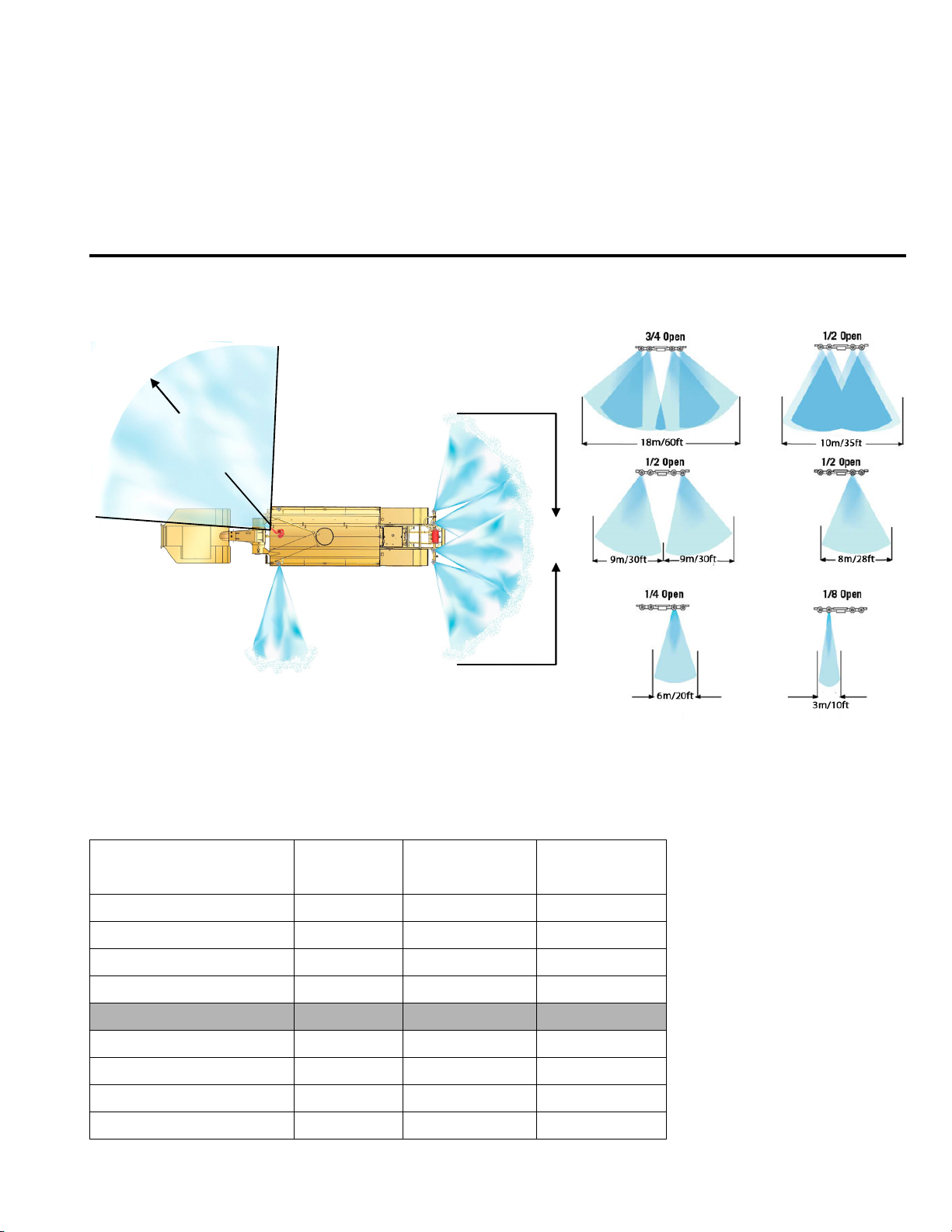
36 - 57 meters
120 - 190 feet
90 degrees
60 feet
18 meters
Performance
Contents
MSC/MST-OPS-1
31 Dec 2013
Spray Pattern and Reach .............................................5-1
Typical Spray System Duration ..................................5-1
Precision Watering ........................................................5-2
Fire Suppression System .............................................5-7
SPRAY PATTERN AND REACH (TYPICAL 9’ SPRAY BAR)
The figures below illustrate width and reach of spray heads and water cannon. Typical spray head deflector fan
adjustments are also depicted.
TYPICAL SPRAY SYSTEM DURATION
The table below contains a standard vehicle spray duration based on spray head deflector opening, vehicle
speed and 18,927 liter (5,000 gallon) capacity.
Number of Spray Heads
and Opening Width
2 Spray Heads@ 1/4” 3611/954 16/10 2.4/1.5
2 Spray Heads@ 1/4” 3611/954 24/15 3.3/2.1
2 Spray Heads@ 3/8” 4705/1243 16/10 1.7/1.1
2 Spray Heads@ 3/8” 4705/1243 24/15 2.5/1.6
4 Spray heads @ 1/4” 5693/1504 16/10 1.4/0.9
4 Spray heads @ 1/4” 5693/1504 24/15 2.0/1.3
4 Spray heads @ 3/8” 5950/1572 16/10 1.2/0.8
4 Spray heads @ 3/8” 5950/1572 24/15 2.0/1.3
LPM/GPM
Ground Speed
(KPH/MPH)
5-1
Max. Distance
(Km./Miles)
Page 37

MSC/MST-OPS-1
31 Dec 2013
SECTION 5
Performance
PRECISION WATERING
The following tables provide precision watering calculations for the installed spray system. Each table is
categorized by size of spray head deflector opening at a full fan width for 2 or 4 spray heads.
1/4 OPENING & FULL FAN (18,927 lit/5,000 gal TANK)
2 SPRAY HEADS (FLOW 3611 lpm/954 gpm) 4 SPRAY HEADS (FLOW 5693 lpm/1504 gpm)
SPRAY
SPEED
MPH FPM (FT) (SQ FT) (GAL/SQ FT) (IN/SQ FT) (FT) (SQ FT) (GAL/SQ FT) (IN/SQ FT)
2 176 1600 96000 0.052 0.084 880 52800 0.095 0.152
5 440 4000 240000 0.021 0.033 2200 132000 0.038 0.061
U
10 880 8000 480000 0.010 0.017 4400 264000 0.019 0.030
S
15 1320 12000 720000 0.007 0.011 6600 396000 0.013 0.020
KPM MPM (METER) (M SQ) (L/M SQ) (MM) (METERS) (M SQ) (M/M SQ) (MM)
M
3 53 675 12147 2.181 2.67 371 6679 3.968 4.65
E
8 134 1706 30712 0.863 1.07 938 16885 1.569 1.84
T
16 268 3412 61423 0.431 0.53 1876 33771 0.785 0.94
R
24 402 5119 92135 0.288 0.35 2814 50656 0.523 0.61
I
DISTANCE
C
TOTAL
COVERAGE
DISPERSAL
WATER
LAYER
MAX
DISTANCE
TOTAL
COVERAGE
DISPERSAL
WATER
LAYER
3/8 OPENING & FULL FAN (18,927 lit/5,000 gal TANK)
2 SPRAY HEADS (FLOW 4705 lpm/1243 gpm) 4 SPRAY HEADS (FLOW 5950 lpm/1572 gpm)
SPRAY
SPEED
MPH FPM (FT) (SQ FT) (GAL/SQ FT) (IN/SQ FT) (FT) (SQ FT) (GAL/SQ FT) (IN/SQ FT)
2 176 1354 81231 0.062 0.099 880 57200 0.087 0.140
5 440 3385 203077 0.025 0.039 2200 143000 0.035 0.056
U
10 880 6769 406154 0.012 0.020 4400 286000 0.017 0.028
S
15 1320 10154 609231 0.008 0.013 6600 429000 0.012 0.019
KPM MPM (METER) (M SQ) (L/M SQ) (MM) (METERS) (M SQ) (M/M SQ) (MM)
M
3 53 571 10276 2.579 3.68 371 6679 3.968 5.59
E
8 134 1443 25980 1.020 1.47 938 16885 1.569 2.23
T
16 268 2887 51960 0.510 0.74 1876 33771 0.785 1.11
R
24 402 4330 77940 0.340 0.48 2814 50656 0.523 0.74
I
DISTANCE
TOTAL
COVERAGE
DISPERSAL
WATER
LAYER
MAX
DISTANCE
TOTAL
COVERAGE
DISPERSAL
C
WATER
LAYER
5-2
Page 38
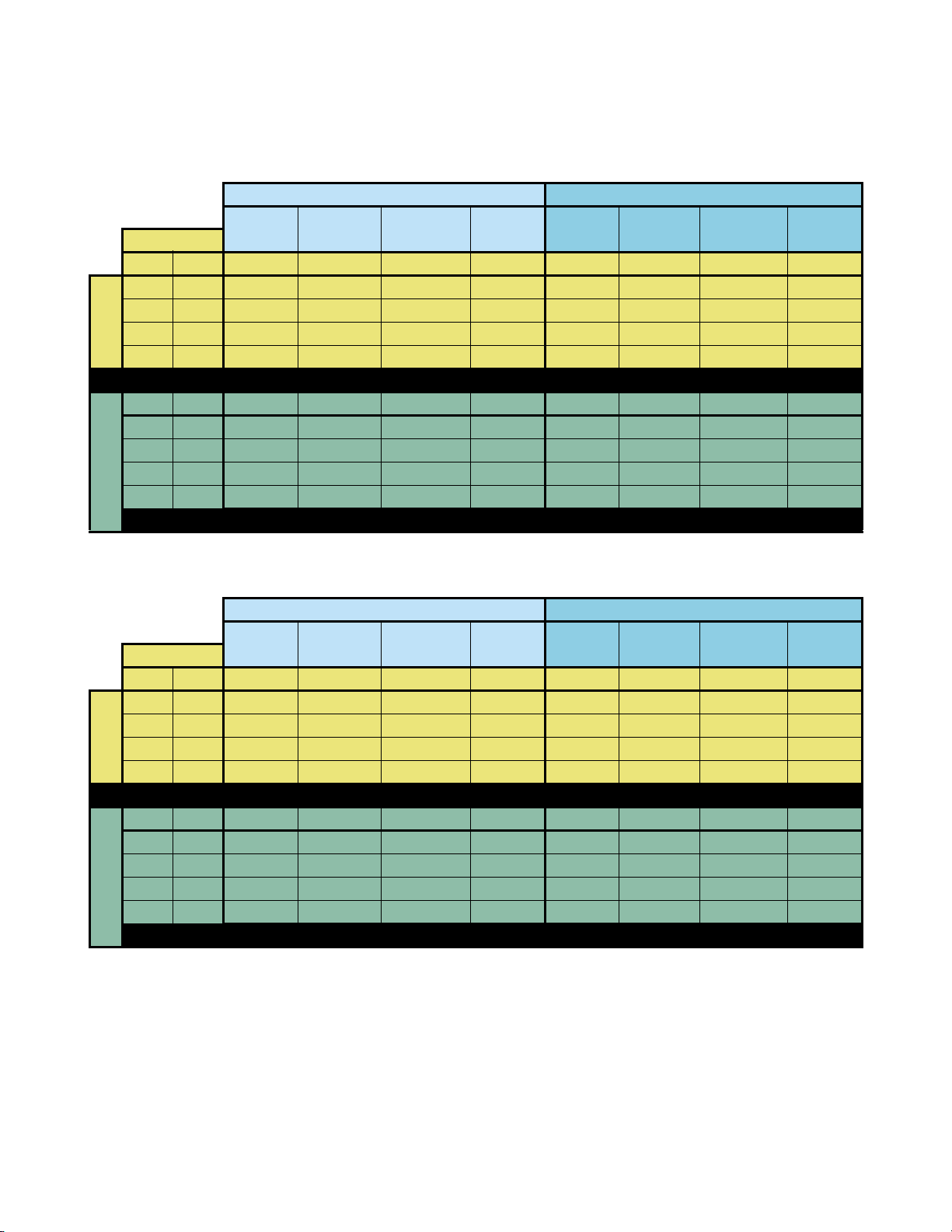
MSC/MST-OPS-1
SECTION 5
Performance
1/4 OPENING & FULL FAN (30,283 lit/8,000 gal TANK)
2 SPRAY HEADS (FLOW 3611 lpm/954 gpm) 4 SPRAY HEADS (FLOW 5693 lpm/1504 gpm)
SPRAY
SPEED
MPH FPM (FT) (SQ FT) (GAL/SQ FT) (IN/SQ FT) (FT) (SQ FT) (GAL/SQ FT) (IN/SQ FT)
2 176 1476 122499 0.065 0.105 936 70213 0.114 0.183
5 440 3690 306247 0.026 0.042 2340 175532 0.046 0.073
U
10 880 7379 612495 0.013 0.021 4681 351064 0.023 0.037
S
15 1320 11069 918742 0.009 0.014 7021 526596 0.015 0.024
KPM MPM (METER) (M SQ) (L/M SQ) (MM) (METERS) (M SQ) (M/M SQ) (MM)
M
3 53 444 11112 2.725 2.67 282 6484 4.670 4.65
E
8 134 1124 28094 1.078 1.07 713 16394 1.847 1.84
T
16 268 2248 56188 0.539 0.53 1426 32788 0.924 0.94
R
24 402 3371 84283 0.359 0.35 2138 49183 0.616 0.61
I
DISTANCE
C
TOTAL
COVERAGE
DISPERSAL
WATER
LAYER
MAX
DISTANCE
TOTAL
COVERAGE
DISPERSAL
31 Dec 2013
WATER
LAYER
3/8 OPENING & FULL FAN (30,283 lit/8,000 gal TANK)
2 SPRAY HEADS (FLOW 4705 lpm/1243 gpm) 4 SPRAY HEADS (FLOW 5950 lpm/1572 gpm)
SPRAY
SPEED
MPH FPM (FT) (SQ FT) (GAL/SQ FT) (IN/SQ FT) (FT) (SQ FT) (GAL/SQ FT) (IN/SQ FT)
2 176 1133 88354 0.091 0.145 896 58219 0.137 0.220
5 440 2832 220885 0.036 0.058 2239 145547 0.055 0.088
U
10 880 5664 441770 0.018 0.029 4478 291094 0.027 0.044
S
15 1320 8496 662655 0.012 0.019 6718 436641 0.018 0.029
KPM MPM (METER) (M SQ) (L/M SQ) (MM) (METERS) (M SQ) (M/M SQ) (MM)
M
3 53 341 8187 3.699 3.68 270 5395 5.613 5.59
E
8 134 862 20699 1.463 1.47 682 13640 2.220 2.23
T
16 268 1725 41399 0.731 0.74 1364 27280 1.110 1.11
R
24 402 2587 62098 0.488 0.48 2046 40920 0.740 0.74
I
DISTANCE
TOTAL
COVERAGE
DISPERSAL
WATER
LAYER
MAX
DISTANCE
TOTAL
COVERAGE
DISPERSAL
C
WATER
LAYER
5-3
Page 39

MSC/MST-OPS-1
31 Dec 2013
SECTION 5
Performance
1/4 OPENING & FULL FAN (37,854 lit/10,000 gal TANK)
2 SPRAY HEADS (FLOW 3611 lpm/954 gpm) 4 SPRAY HEADS (FLOW 5693 lpm/1504 gpm)
SPRAY
SPEED
MPH FPM (FT) (SQ FT) (GAL/SQ FT) (IN/SQ FT) (FT) (SQ FT) (GAL/SQ FT) (IN/SQ FT)
2 176 1845 153124 0.065 0.105 1170 87766 0.114 0.183
5 440 4612 382809 0.026 0.042 2926 219415 0.046 0.073
U
10 880 9224 765618 0.013 0.021 5851 438830 0.023 0.037
S
15 1320 13836 1148428 0.009 0.014 8777 658245 0.015 0.024
KPM MPM (METER) (M SQ) (L/M SQ) (MM) (METERS) (M SQ) (M/M SQ) (MM)
M
3 53 556 13890 2.725 2.67 352 8105 4.670 4.65
E
8 134 1405 35118 1.078 1.07 891 20493 1.847 1.84
T
16 268 2809 70236 0.539 0.53 1782 40986 0.924 0.94
R
24 402 4214 105354 0.359 0.35 2673 61479 0.616 0.61
I
DISTANCE
C
TOTAL
COVERAGE
DISPERSAL
WATER
LAYER
MAX
DISTANCE
TOTAL
COVERAGE
DISPERSAL
WATER
LAYER
3/8 OPENING & FULL FAN (37,854 lit/10,000 gal TANK)
2 SPRAY HEADS (FLOW 4705 lpm/1243 gpm) 4 SPRAY HEADS (FLOW 5950 lpm/1572 gpm)
SPRAY
SPEED
MPH FPM (FT) (SQ FT) (GAL/SQ FT) (IN/SQ FT) (FT) (SQ FT) (GAL/SQ FT) (IN/SQ FT)
2 176 1416 110442 0.091 0.145 1120 72774 0.137 0.220
5 440 3540 276106 0.036 0.058 2799 181934 0.055 0.088
U
10 880 7080 552212 0.018 0.029 5598 363868 0.027 0.044
S
15 1320 10619 828319 0.012 0.019 8397 545802 0.018 0.029
KPM MPM (METER) (M SQ) (L/M SQ) (MM) (METERS) (M SQ) (M/M SQ) (MM)
M
3 53 426 10234 3.699 3.68 337 6744 5.613 5.59
E
8 134 1078 25874 1.463 1.47 853 17050 2.220 2.23
T
16 268 2156 51749 0.731 0.74 1705 34100 1.110 1.11
R
24 402 3234 77623 0.488 0.48 2558 51151 0.740 0.74
I
DISTANCE
TOTAL
COVERAGE
DISPERSAL
WATER
LAYER
MAX
DISTANCE
TOTAL
COVERAGE
DISPERSAL
C
WATER
LAYER
5-4
Page 40

MSC/MST-OPS-1
31 Dec 2013
SECTION 5
Performance
FIRE SUPPRESSION SYSTEM
The table below shows consumption rates and duration of foam suppression concentrate and water based
upon a standard flow rate 1893 lpm/500 gpm and 3% foam proportioning.
Foam Concentrate
liters/gallons
57/15 1893/500 1 minute
114/30 3786/1000 2 minutes
228/60 7571/2000 4 minutes
341/90 11,357/3000 6 minutes
455/120 15,142/4000 8 minutes
Water
liters/gallons
Duration
5-5
Page 41

MSC/MST-OPS-1
31 Dec 2013
SECTION 5
Performance
5-6 (Blank)
Page 42

MSC/MST-OPS-1
31 Dec 2013
SECTION 6
Employment
Contents
Description .......................................................................6-1 GPS Ground Speed Sensing .......................................6-1
DESCRIPTION
This section provides descriptions, guidance, and
techniques used when employing the MEGA spray
system. These best practices will provide operators
with several different choices that will result in
maximum system performance in most applications
with ever changing conditions.
GPS GROUND SPEED SENSING
The resident software provides a consistent layer of
water on haul roads regardless of ground speed. The
software minimizes water usage and prevents
puddling at stops and haul ramps. Nominal settings
produce about 3 liters per cubic meter regardless of
ground speed. This maximizes water usage and
extends the duration of a given load of water.
Adjustments are provided to increase or decrease the
layer of water dispersed, as well as setting maximum
water flow at a desired ground speed. All automatic
system protection features are active regardless of
auto or manual modes.
EXAMPLE 2
Setup:
1. RATE - Set at midpoint (50%)
2. SPEED - Set at mid-point (approximately
24 KPH/15 MPH)
3. AUTO – ON
4. Spray heads - Select all 4 spray heads
5. Vehicle speed – Greater than 27 KPH/16 MPH
Observed Operation:
1. All 4 requested spray heads ON, NO timed
cycle
EXAMPLE 3
Setup:
1. RATE - Set LESS than midpoint (≤50%)
2. SPEED - Set at mid-point (approximately
24 KPH/15 MPH)
3. AUTO – ON
4. Spray heads - Select all 4 spray heads
5. Vehicle speed – Less than 21 KPH/14 MPH
Here are several examples of initial system setup and
adjustments:
EXAMPLE 1
Setup:
1. RATE - Set at midpoint (50%)
2. SPEED - Set at mid-point (approximately
15 MPH/24 KPH)
3. AUTO – ON
4. Spray heads - Select all 4 spray heads
5. Vehicle speed – Less than 21 KPH/14 MPH
Observed Operation:
1. 2 Outer spray heads on with a timed cycle,
shortened ON cycle durations
2. 2 Center spray heads OFF (reduced volume)
Observed Operation:
1. 2 Outer spray heads on with a timed cycle,
shortened ON cycle durations
2. 2 Center spray heads OFF (reduced volume)
EXAMPLE 4
Setup:
1. RATE - Set at GREATER than midpoint (≥50%)
2. SPEED - Set at mid-point (approximately
24 KPH/15 MPH)
3. AUTO – ON
4. Spray heads - Select all 4 spray heads
5. Vehicle speed – Less than 21 KPH/14 MPH
Observed Operation:
1. 2 Outer spray heads on with a timed cycle,
increased ON cycle durations
2. 2 Center spray heads OFF (reduced volume)
6-1
Page 43

MSC/MST-OPS-1
31 Dec 2013
SECTION 6
Employment
6-2 (Blank)
Page 44

MSC/MST-OPS-1
31 Dec 2013
SECTION 7
Appendix
MSC/MST-OPS(CL)-1
31 Dec 2013
MSC/MST
OPERATOR’S
CHECKLIST
7-1
Page 45

MSC/MST-OPS-1
31 Dec 2013
SECTION 7
Appendix
MSC/MST-OPS(CL)-1
31 Dec 2013
TABLE OF CONTENTS
Title Page
1. BEFORE OPERATIONS . . . . . . . . . . . . . . . . . . . N-2
2. OPERATIONS
A. Spray Head System. . . . . . . . . . . . . . . . . . N-4
B. GPS AUTO Mode . . . . . . . . . . . . . . . . . . . . N-5
C. Dump Bar. . . . . . . . . . . . . . . . . . . . . . . . . . . N-7
D. Water Cannon. . . . . . . . . . . . . . . . . . . . . . . N-8
E. Fire Suppression System. . . . . . . . . . . . . N-9
F. Tank Drain . . . . . . . . . . . . . . . . . . . . . . . . . . N-11
G. Hose Reel . . . . . . . . . . . . . . . . . . . . . . . . . . . N-12
3. AFTER OPERATIONS. . . . . . . . . . . . . . . . . . . . . N-14
4. COLD WEATHER OPERATION
AND STORAGE. . . . . . . . . . . . . . . . . . . . . . . . . . N-15
N-1
7-2
Page 46

SECTION 7
Appendix
MSC/MST-OPS(CL)-1
31 Dec 2013
BEFORE OPERATIONS
These procedures are used to perform a walk-around
inspection of the MEGA water tanker system before
use or beginning of a shift. This inspection is in
addition to and does not replace the vehicle
manufacturer’s inspection requirements.
1. Chocks – As Required
MSC/MST-OPS-1
31 Dec 2013
2. Vehicle Parking Brake – ON
3. Cab Control Switches – SET OFF
4. Bumper Sprayheads – SECURED & SET
5. Vehicle Hydraulic Tank – SERVICED
6. Gooseneck Lines & Hoses – CHECKED & SECURED
7. Solenoid Control Box – CHECKED AND SECURED
8. Water Cannon – CHECKED & SECURED
a. Nozzle – Check for security and kinking of
foam concentrate supply line.
N-2
7-3
Page 47

MSC/MST-OPS-1
31 Dec 2013
SECTION 7
Appendix
MSC/MST-OPS(CL)-1
31 Dec 2013
9. (If Equipped) Foam Concentrate Level –
CHECKED. At least 1” from the top of the foam
tank.
Ensure PPE fall arrest harness is worn, adjusted
properly and attached to an anchor point. Failure
to use PPE properly may result in personnel
injury or death.
10. Tank Drain Petcocks – CLOSED
11. Spray Heads – SECURED & SET
12. Water Pump Assembly – CHECKED
a. Water Pump – Check to ensure volute case
drain valve is closed.
b. Water pump and drive motor for evidence of
overheating.
13. Hose Reel – CHECKED
N-3
7-4
Page 48

SECTION 7
Appendix
MSC/MST-OPS(CL)-1
31 Dec 2013
OPERATIONS
Use these procedures to safely operate the standard
and optional systems installed on the MEGA water
tanker.
Limit water pump operation to 2.5 minutes when in a
no-flow condition (no flow from spray heads, dump
bar, water cannon, drain valve or hose reel). Water
pump operation in a no flow condition will cause
overheating of the water pump and damage to the
shaft bearings.
MSC/MST-OPS-1
31 Dec 2013
SPRAY HEAD SYSTEM
Operating more than 4 spray heads simultaneously
will greatly reduce the width and flow of active spray
heads.
1. Cab Control SYSTEM/POWER Switch – ON
2. INTERMITTENT – SET AS REQUIRED
a. TIMER ON/OFF Dials – SET
b. INTERMITTENT Switch – SET
N-4
7-5
Page 49
MSC/MST-OPS-1
31 Dec 2013
SECTION 7
Appendix
MSC/MST-OPS(CL)-1
31 Dec 2013
3. PUMP Switch – ON
Engaging/disengaging the water pump above
LOW IDLE may result in water pump component
damage and reduced service life.
4. Individual Spray Head Switches – ON
Once operations are complete:
5. Individual Spray Head Switches – OFF
6. PUMP Switch – OFF
Engaging/disengaging the water pump above
LOW IDLE may result in water pump component
damage and reduced service life.
7. Cab Control SYSTEM/POWER Switch – OFF
GPS AUTO MODE
1. Cab Control POWER Switch – ON
2. RATE and SPEED Dials - SET
N-5
7-6
Page 50

SECTION 7
Appendix
MSC/MST-OPS(CL)-1
31 Dec 2013
3. AUTO – ON AS REQUIRED
4. Desired Spray Head Switches – ON
5. PUMP Switch ON
Engaging/disengaging the water pump above
LOW IDLE may result in water pump component
damage and reduced service life.
MSC/MST-OPS-1
31 Dec 2013
Once operations are complete:
6. PUMP Switch OFF
Engaging/disengaging the water pump above
LOW IDLE may result in water pump component
damage and reduced service life.
7. AUTO – OFF
8. Individual Spray Head Switches – OFF
9. Cab Control POWER Switch - OFF
N-6
7-7
Page 51
MSC/MST-OPS-1
31 Dec 2013
SECTION 7
Appendix
MSC/MST-OPS(CL)-1
31 Dec 2013
DUMP BAR
1. Cab Control SYSTEM/POWER Switch – ON
2. INTERMITTENT – SET AS REQUIRED
a. Timer ON/OFF Dials – SET
b. INTERMITTENT Switch – SET
3. PUMP Switch ON
Engaging/disengaging the water pump above
LOW IDLE may result in water pump component
damage and reduced service life.
4. DUMP BAR Switch – ON
Once operations are complete:
5. DUMP BAR Switch – OFF
6. PUMP Switch OFF
Engaging/disengaging the water pump above
LOW IDLE may result in water pump component
damage and reduced service life.
7. Cab Control SYSTEM/POWER Switch – OFF
N-7
7-8
Page 52

SECTION 7
Appendix
MSC/MST-OPS(CL)-1
31 Dec 2013
WATER CANNON
1. Cab Control SYSTEM/POWER Switch – ON
2. PUMP Switch ON
Engaging/disengaging the water pump above
LOW IDLE may result in water pump component
damage and reduced service life.
MSC/MST-OPS-1
31 Dec 2013
3. Water Cannon – Pointed in a safe direction.
4. MONITOR/BFV Switch – ON
5. Water Cannon Joystick – As Required.
6. MONITOR/BFV Switch – OFF
Once operations are complete:
7. Water Cannon Nozzle - STOW
Manual and remote adjustable nozzles must be
stowed pointing vertically to reduce wear on
water cannon joints. Leaving the nozzle in any
other position will cause increased wear on water
cannon joints and result in premature joint
failure.
N-8
7-9
Page 53

MSC/MST-OPS-1
31 Dec 2013
SECTION 7
Appendix
MSC/MST-OPS(CL)-1
31 Dec 2013
8. PUMP Switch OFF
Engaging/disengaging the water pump above
LOW IDLE may result in water pump component
damage and reduced service life.
9. Cab Control SYSTEM/POWER Switch – OFF
FIRE SUPPRESSION SYSTEM
1. Cab Control SYSTEM/POWER Switch – ON
2. PUMP Switch ON
Engaging/disengaging the water pump above
LOW IDLE may result in water pump component
damage and reduced service life.
3. Water Cannon – Pointed in a safe direction.
4. FOAM Switch – ON
5. MONITOR/BFV Switch – ON
6. Water Cannon Joystick – As Required.
N-9
7-10
Page 54
SECTION 7
Appendix
MSC/MST-OPS(CL)-1
31 Dec 2013
Once operations are complete:
7. FOAM Switch – OFF
8. Water Cannon – Flow water through the water
cannon nozzle with the FOAM switch off to flush
foam from the nozzle.
MSC/MST-OPS-1
31 Dec 2013
9. MONITOR/BFV Switch – OFF
10. Water Cannon Nozzle - STOW
Manual and remote adjustable nozzles must be
stowed pointing vertically to reduce wear on
water cannon joints. Leaving the nozzle in any
other position will cause increased wear on water
cannon joints and result in premature joint
failure.
11. PUMP Switch OFF
Engaging/disengaging the water pump above
LOW IDLE may result in water pump component
damage and reduced service life.
12. Cab Control SYSTEM/POWER Switch – OFF
N-10
7-11
Page 55

MSC/MST-OPS-1
31 Dec 2013
SECTION 7
Appendix
MSC/MST-OPS(CL)-1
31 Dec 2013
13. Vehicle – Wash or fresh water rinse areas exposed
to the foam spray.
TANK DRAIN
1. Cab Control SYSTEM/POWER Switch – ON
2. PUMP Switch ON
Engaging/disengaging the water pump above
LOW IDLE may result in water pump component
damage and reduced service life.
3. DRAIN Switch – ON
4. Water Level – Drain to desired level.
Do not operate the water pump in a dry sump.
Dry running operation will cause water pump
failure.
Once operations are complete:
5. DRAIN Switch – OFF
N-11
7-12
Page 56
SECTION 7
Appendix
MSC/MST-OPS(CL)-1
31 Dec 2013
6. PUMP Switch OFF
Engaging/disengaging the water pump above
LOW IDLE may result in water pump component
damage and reduced service life.
7. Cab Control SYSTEM/POWER Switch – OFF
MSC/MST-OPS-1
31 Dec 2013
HOSE REEL
1. Hose Nozzle – CLOSED
2. Hose – Deploy desired length.
3. Gate Valve – OPEN
4. Cab Control SYSTEM/POWER Switch – ON
5. PUMP Switch ON
Engaging/disengaging the water pump above
LOW IDLE may result in water pump component
damage and reduced service life.
6. Vehicle RPM – SET
7. Hose Nozzle – OPEN as desired.
N-12
7-13
Page 57

MSC/MST-OPS-1
31 Dec 2013
SECTION 7
Appendix
MSC/MST-OPS(CL)-1
31 Dec 2013
Once operations are complete:
8. Hose Nozzle – CLOSED
9. Vehicle RPM – LOW IDLE
10. PUMP Switch OFF
Engaging/disengaging the water pump above
LOW IDLE may result in water pump component
damage and reduced service life.
11. Cab Control SYSTEM/POWER Switch – OFF
12. Gate Valve – CLOSED
13. Hose – Reel in and stow hose nozzle.
N-13
7-14
Page 58

SECTION 7
Appendix
MSC/MST-OPS(CL)-1
31 Dec 2013
AFTER OPERATIONS
These procedures are used to perform a walk-around
inspection after using the MEGA water tanker
systems. This inspection is in addition to and does
not replace the vehicle manufacturer’s inspection
requirements.
1. Vehicle parking brake – ON
MSC/MST-OPS-1
31 Dec 2013
2. Cab Control Switches – SET OFF
3. Chocks – As Required.
4. Water Cannon – CHECKED AND SECURED
5. Vehicle Hydraulic Tank – CHECKED
6. Tank Lines and Hoses – SECURED
7. Tank Drain Petcocks – As Required.
8. Spray Heads – SECURED AND SET
9. Water Pump Assembly – CHECKED
a. Water Pump – Check for damage and volute
case drain valve set as required.
10. Hose Reel – CHECKED
N-14
7-15
Page 59

MSC/MST-OPS-1
31 Dec 2013
SECTION 7
Appendix
MSC/MST-OPS(CL)-1
31 Dec 2013
11. Solenoid Control Box – CHECKED
COL D W E AT HER OPERATION AND STO R AGE
Ice will cause serious damage to water pump, spray
heads, butterfly valves, water-to-oil cooler, and the
water cannon if water is allowed to freeze in the
volute case, water piping, or on top of a closed
butterfly valve. Ensure all water is drained from
system when the temperatures are expected to fall
below 4.4°C (40°F) for any period of time. Failure to
ensure all systems are drained and free from
standing water will result in shaft, operator,
diaphragm, drive motor, water pump, or butterfly
valve damage when operation is attempted with ice
in the housings.
To ensure all water is drained from tank check the
following;
1. Park unit on a slight nose up angle to allow water
to flow to the rear of the tank.
2. Drain the tank using an appropriate method until
the Water Level Gauge reads EMPTY.
3. Open all drain petcocks (water pump, spray bars,
etc.).
N-15
7-16
Page 60

SECTION 7
Appendix
MSC/MST-OPS(CL)-1
31 Dec 2013
4. Remove water pump sump cover.
5. Start engine.
6. Cab Control SYSTEM/POWER Switch – ON
7. MONITOR/BFV Switch – ON
MSC/MST-OPS-1
31 Dec 2013
8. DUMP BAR Switch – ON
9. DRAIN Switch – ON
10. Water Cannon Nozzle – Pointed fully DOWN
11. Turn engine off.
12. Cab Control SYSTEM/POWER Switch – OFF
13. Hose Reel – DRAIN
a. Hose – UNWIND
b. Nozzle – Fully OPEN
c. Gate Valve – OPEN
d. Allow water to drain.
e. Hose – REWIND
f. Gate Valve – CLOSED
g. NOZZLE – CLOSED
14. Check to ensure all water has drained from tank.
N-16
7-17
Page 61

MSC/MST-OPS-1
31 Dec 2013
SECTION 7
Appendix
MSC/MST-OPS(CL)-1
31 Dec 2013
TO REACTIVATE UNIT:
1. Lubricate water pump bearings as instructed in
the Maintenance (-2) technical manual.
2. Inspect tank interior to ensure it is clean, if the
tank is coated, ensure coating integrity, clean or
repair as required.
3. Install sump cover with new gasket.
4. Close all drain valves and petcocks.
5. Start engine.
6. Control SYSTEM/POWER Switch – ON
7. Individual Spray Head Switches – OFF
8. DUMP BAR Switch – OFF
9. DRAIN Switch – OFF
10. MONITOR/BFV Switch – OFF
11. Turn engine off.
12. Cab Control SYSTEM/POWER Switch – OFF
N-17
7-18
 Loading...