

MEGA Corp. MPT User Manual
GENUINE MEGA.
MPT
MEGA PORTABLE TANK
TECHNICAL MANUAL
SPECIALTY HAULAGE SOLUTIONS FOR CONSTRUCTION AND MINING
MEGA CORP.®
700 Osuna Rd. N.E. • Albuquerque, NM 87113 • 1-800-345-8889 • 505-345-2661 • Fax 505-345-6190
www.megacorpinc.com
® MEGA Corp., Inc. All Rights Reserved

MPT12 Manual
26 Mar 2014
TABLE OF CONTENTS
Page
Section 1 Definitions and Abbreviations . . . . . . . . . . . . . . . . . . . . . . . . . . . . . . . . . . . . . . . . . . . . . . . . .1-1
Section 2 System Description. . . . . . . . . . . . . . . . . . . . . . . . . . . . . . . . . . . . . . . . . . . . . . . . . . . . . . . . . . . .2-1
Section 3 Commissioning . . . . . . . . . . . . . . . . . . . . . . . . . . . . . . . . . . . . . . . . . . . . . . . . . . . . . . . . . . . . . . . 3-1
Section 4 Operation Instructions. . . . . . . . . . . . . . . . . . . . . . . . . . . . . . . . . . . . . . . . . . . . . . . . . . . . . . . . . 4-1
Section 5 Maintenance and Repair. . . . . . . . . . . . . . . . . . . . . . . . . . . . . . . . . . . . . . . . . . . . . . . . . . . . . . .5-1
Section 6 Scheduled Maintenance Inspections . . . . . . . . . . . . . . . . . . . . . . . . . . . . . . . . . . . . . . . . . . .6-1
Section 7 Recommended Support Parts. . . . . . . . . . . . . . . . . . . . . . . . . . . . . . . . . . . . . . . . . . . . . . . . . . 7-1
Section 8 Illustrated Parts Breakdown. . . . . . . . . . . . . . . . . . . . . . . . . . . . . . . . . . . . . . . . . . . . . . . . . . . .8-1
Section 9 Appendix: Installation Drawings . . . . . . . . . . . . . . . . . . . . . . . . . . . . . . . . . . . . . . . . . . . . . . .9-A
A

MPT12 Manual
26 Mar 2014
TABLE OF CONTENTS
B (Blank)
SECTION 1
Definitions and Abbreviations
Contents
MPT12 Manual
26 Mar 2014
Manual Usage ...................................................................1-1
Warning, Caution And Notes ......................................1-1
Use Of Shall, Will, Should And May ...........................1-1
MANUAL USAGE
This technical manual only contains information
required to safely operate and maintain the Mega
Portable Tank. If your system is not covered in this
manual please contact MEGA Corp. Product Support
at: 1-800-345-8889 or visit our website at
www.megacorpinc.com for more detailed
information.
The exact location of the hazards and description of
the hazards are reviewed in this section. All personnel
working on or operating the machine must become
familiarized with all the safety messages.
Due to the nature of these processes, ensure that all
safety information, warnings and instructions are
read and understood before any operation or any
maintenance procedures are performed. Some
procedures take place with heavy components and
at moderate heights, ensure proper safety
procedures are maintained when performing these
actions. Failure to use and maintain proper safety
equipment and procedures will cause injury, death or
damage to equipment.
Safety Messages ..............................................................1-2
Abbreviations ...................................................................1-3
MPT Overview (Typical) ................................................1-4
WARNING, CAUTION AND NOTES
The following definitions are found throughout the
manual and apply as follows:
Operating procedures and techniques, which could
result in personal injury and/or loss of life if not
carefully followed.
Operating procedures and techniques, which could
result in damage to equipment if not carefully
followed.
Operating procedures and techniques that are
considered essential to emphasize.
USE OF SHALL, WILL, SHOULD AND MAY
Shall and Will – Used when application of a
procedure is mandatory.
Should – Used when application of a procedure is
recommended.
May - Used to indicate an acceptable or suggested
means of accomplishment.
1-1
MPT12 Manual
26 Mar 2014
SECTION 1
Definitions and Abbreviations
SAFETY MESSAGES
There are several specific safety messages applicable
to this machine. Some of these safety messages have
associated warning labels located on the machine.
The descriptions of the hazards and the locations (if
applicable) of their warning labels are reviewed in
this section. All personnel working on or operating
the machine must become familiarized with all the
safety messages.
Make sure that all of the safety labels are legible.
Clean or replace the safety labels if you cannot read
the words. Replace the illustrations if the illustrations
are not legible. When you clean the safety labels, use
a cloth, water and soap. Do not use solvent, gasoline
or other harsh chemicals to clean the safety labels.
Solvents, gasoline or harsh chemicals could loosen
the adhesive that secures the safety labels. Loose
adhesive will allow the safety labels to detach.
Replace any safety label that is damaged or missing.
If a safety label is attached to a part that is replaced,
install a new safety label on the replacement part.
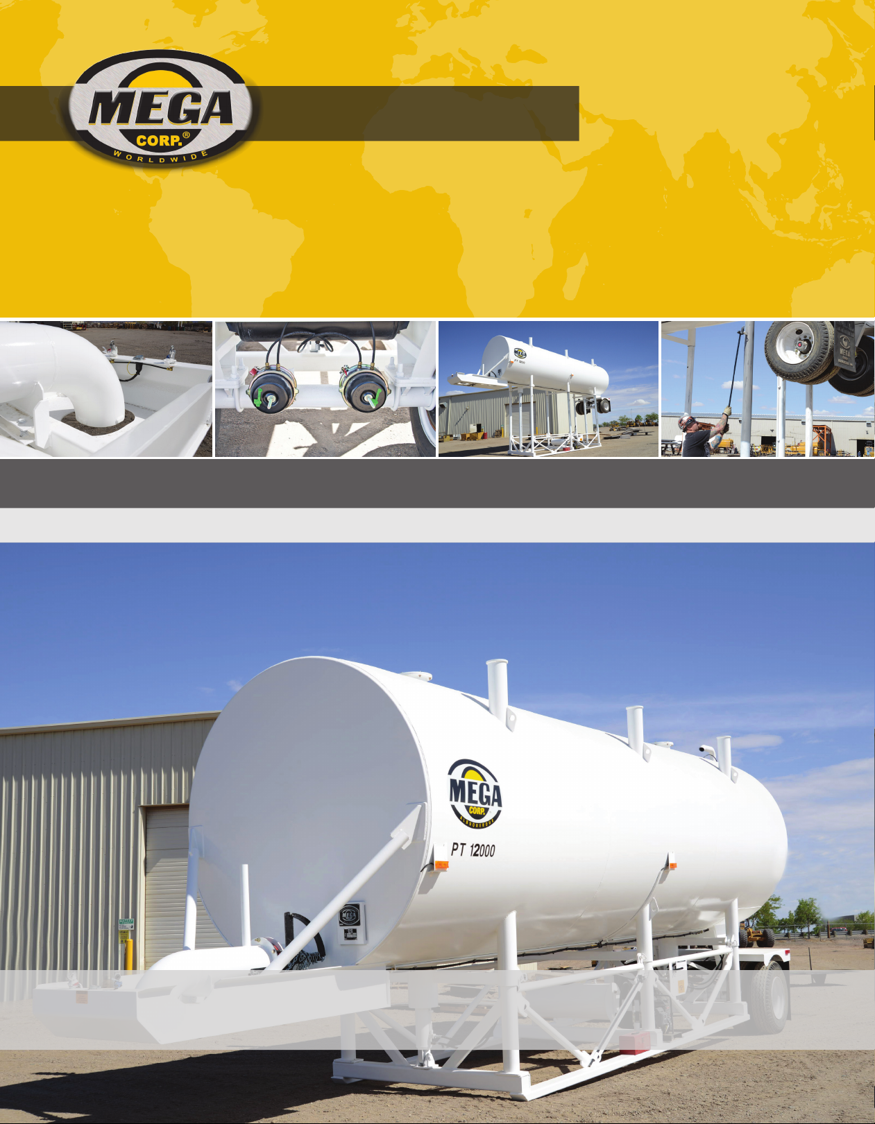
FREEZING (2)
This safety label is located on the front of the
machine, by the discharge pipe..
Drain tank, fill pipe, and drain valve in freezing
weather. Refer to the Operator and Maintenance
Manual for the procedure to follow.
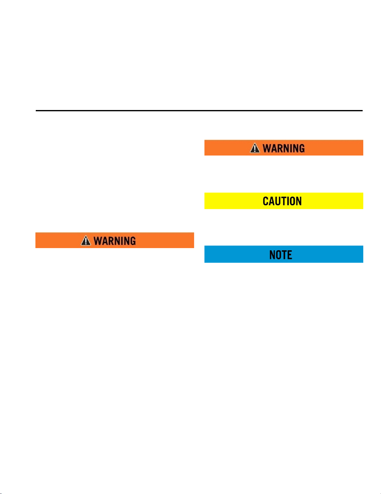
TOXIC GAS HAZ ARD ( 1)
Cutting or welding operation on the inside of the
tank can cause the accumulation of toxic gases.
Read and understand instructions and warnings
in the Maintenance Manual. Failure to provide
proper ventilation or breathing apparatus while
conducting these operations may result in serious
injury or death.
NON-POTABLE (3)
This safety label is located at the rear of the tank, near
the ladder.
Water held within tank is not potable. Do not use
tank for transport of water intended for human or
animal consumption or serious injury or death
may result.
1-2
SECTION 1
Definitions and Abbreviations
MPT12 Manual
26 Mar 2014
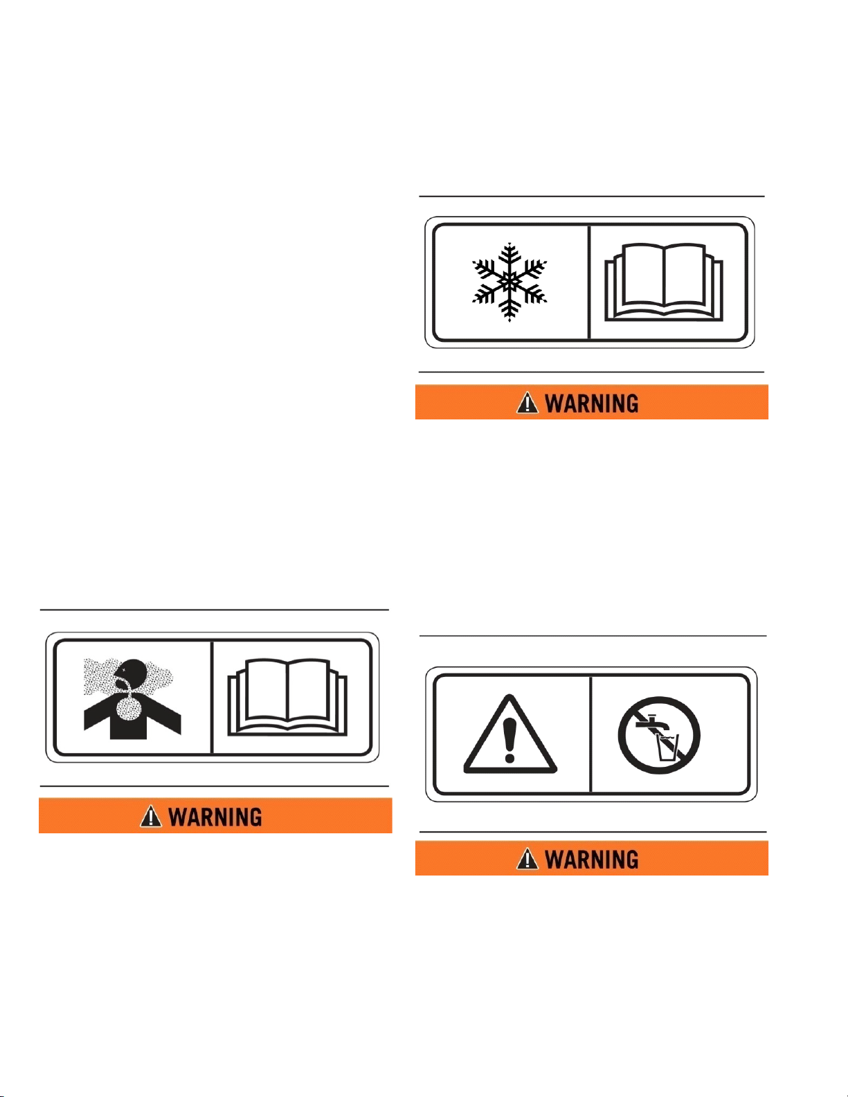
FALL HAZARD (4)
Do not walk on the top of tank without fall arrest
PPE. Serious injury or death could occur from a
fall.
HIGH PRESSURE MOTOR (5)
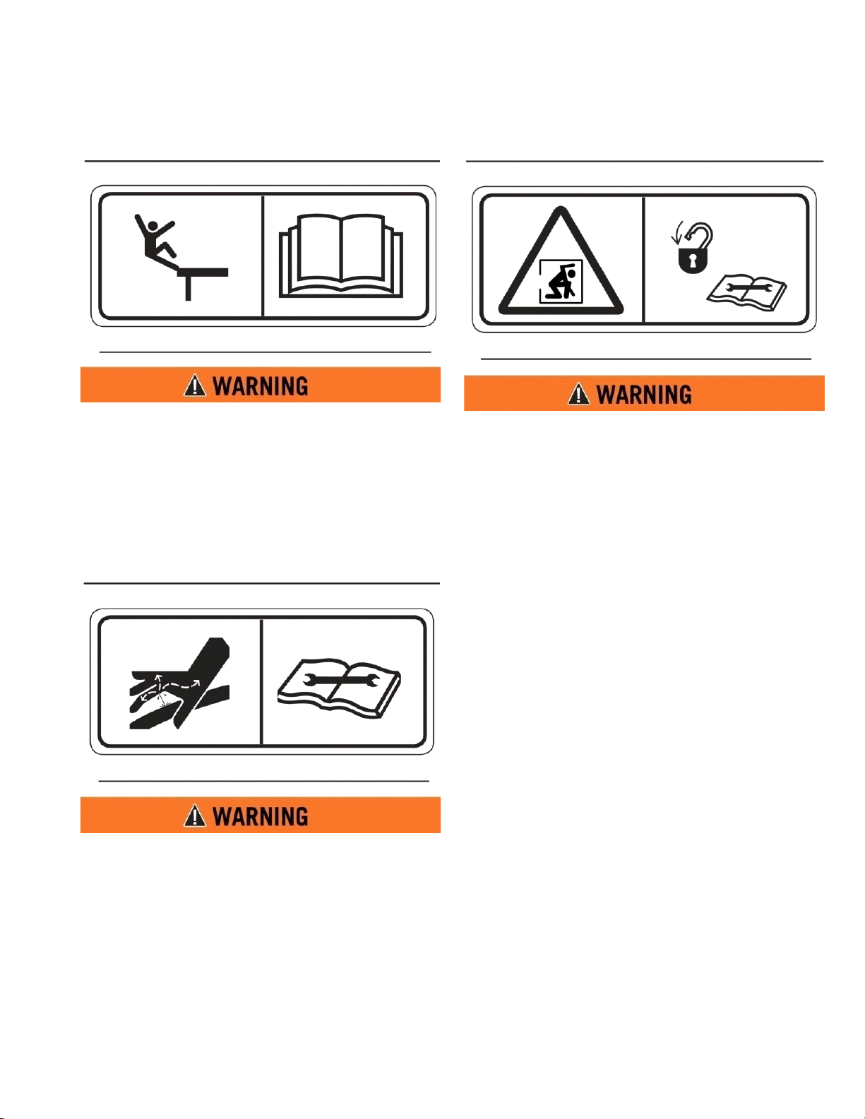
CONFINED SPACE (6)
Do not enter confined spaces without following
established site specific procedures. Failure to
follow proper safety procedures will result in
serious injury or death.
ABBREVIATIONS
BFV - Butterfly Valve
CCW - Counterclockwise
CW - Clockwise
FIP - Fault Isolation Procedures
Ft-lbs - Foot Pounds of Torque
GPM - Gallons per Minute
IPB - Illustrated Parts Breakdown
LT - Left (as viewed from the rear of the
vehicle looking forward)
MPT - Mega Portable Tank
n-m - Newton Meters of Torque
PSI - Pounds per Square Inch
RT - Right (as viewed from the rear of the
vehicle looking forward)
RPM - Revolutions per minute
Hydraulic motor and supply lines contain oil
under high pressure. Improper removal and
repair procedures could cause severe injury. To
remove or repair, instructions in the Maintenance
Manual must be followed.
1-3

MPT12 Manual
8
1
5
2
4
6
1
HYDRAULIC CYLINDERS
2
ENGINE & HYDRAULIC PUMP
3
LEVER CONTROL SYSTEM
4
FILL PIPE
5
FILL PIPE VALVE
6
ACCESS LADDER
7
TOOL BOX
8
DISCHARGE TUBE
9
D.O.T. LIGHTS
10
HYDRAULIC TANK
REAR VIEW
SIDE VIEW
1
1
3
7
5
4
6
9 9
9
10
10
26 Mar 2014
SECTION 1
Definitions and Abbreviations
MPT OVERVIEW (TYPICAL)
1-4
SECTION 2
System Description
Contents
MPT12 Manual
26 Mar 2014
Description.........................................................................2-1
MPT Tank .............................................................................2-1
Self-Raising System .........................................................2-1
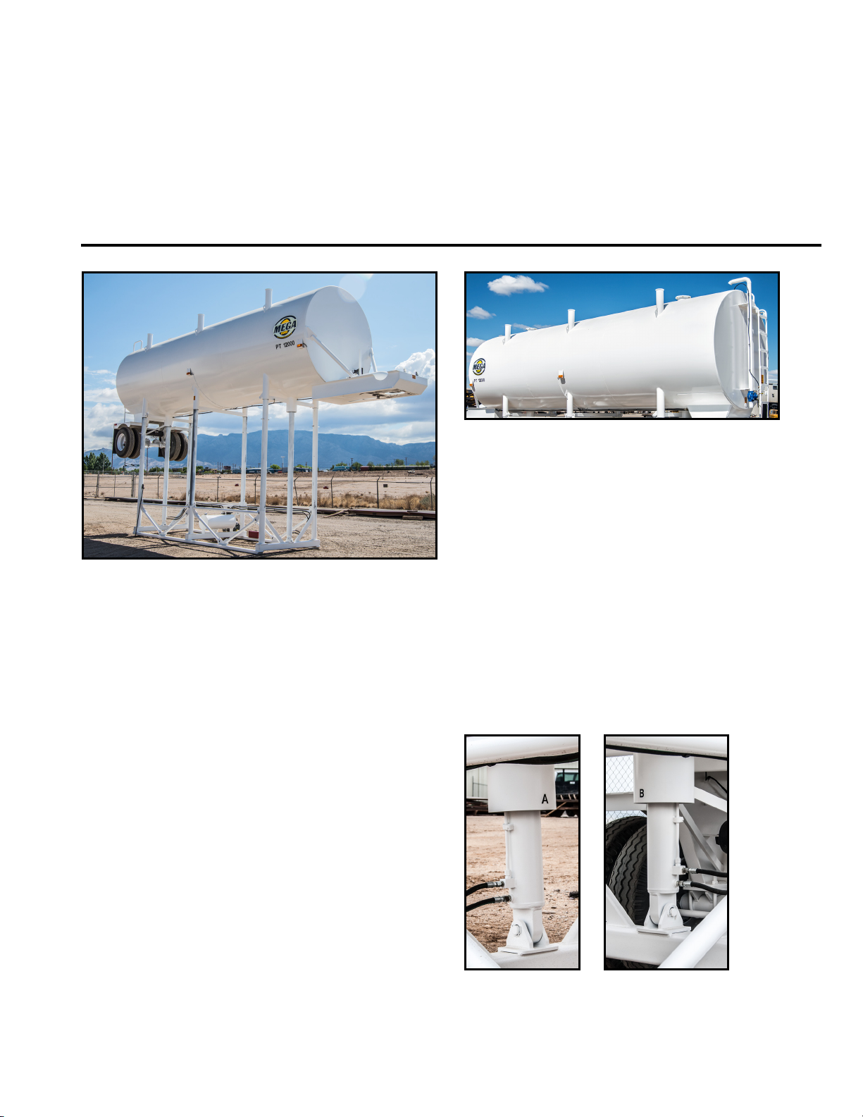
DESCRIPTION
The Mega Portable Tank (MPT) is a 12,000 gallon
platform or stand tank designed for towing with a
fifth-wheel on-highway tractor. The Mega MPT is
used to rapidly fill water distribution equipment to
maximize productivity. All Mega MPTs are selferecting by use of an engine-driven hydraulic pump
and hoist cylinders with pin locks. Mega MPTs have a
12 inch diameter discharge pipe capable of filling a
5,000 gallon tank in approximately 2 minutes. The
MPT can be filled from a municipal water source or
with other water pumping equipment. The 3” fill pipe
is equipped with an automatic shut off to prevent
overfilling.
Water Discharge System ............................................... 2-2
Axle .......................................................................................2-2
MPT TANK
The MPT tank is 2.59m (8.5 ft) in diameter, 11.13m
(36.5 ft.) in length, and has a capacity of 45.42 L
(12,000 gallons). The corners of the tank are
reinforced to provide sturdy connection to supports.
An access ladder leading to the top of the tank is
located at the rear of the trailer, and a ladder is
located inside of the tank. An 8” diameter float is
located inside of the tank for automatic fill shut-off
when the tank is full.
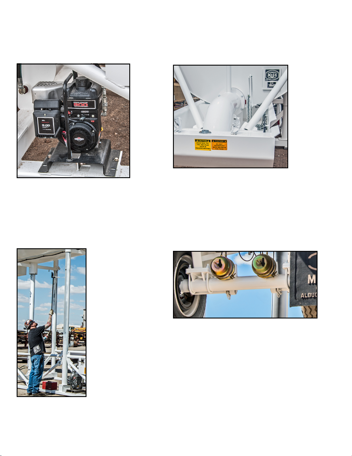
SELF-RAISING SYSTEM
The MPT’s self-raising system incorporates dual
hydraulic cylinders and a 6.5 horsepower engine with
a hydraulic pump.
HYDRAULIC CYLINDERS
The MPT is designed to comply with all Department
of Transportation requirements, and is available in
custom colors and with special signage as specified
by the customer. For more information, please
contact the Mega Sales Department at 1-800-3458889, or contact your local dealer.
Dual 127mm (5 inch) diameter double-acting
hydraulic cylinders that allow the tank to be raised for
connection to a tractor. The frame can be lifted with
the same cylinders after tractor hook-up is complete.
2-1
MPT12 Manual
26 Mar 2014
SECTION 2
System Description
ENGINE
A 6.5 horsepower engine and hydraulic pump that is
mounted on the base of the MPT. The engine is
equipped with a handle for removal and storage after
the tank has been locked in the raised position. Quick
disconnects for the lines to the hydraulic pump are
located on the structure for storage of the hydraulic
hoses after the motor/pump package is removed.
WATER DISCHARGE SYSTEM
The MPT’s water discharge system includes a 10 inch
diameter discharge pipe with a flow rate of
approximately 2,000 gal/min, a shut-off valve with a
constant force wheel to ensure positive closure, a
weight and pulley system to secure the chain while
positioning the tanker beneath the discharge pipe
spout, and a canvas discharge sock for the discharge
pipe spout.
PIN HANDLER
The Mega Pin Handler is a tool that allows a person to
install and remove all six (6) MPT hitch pins while
standing at ground level, eliminating the need for a
ladder and saving time in the process.
AXLE
The heavy-duty utility axle has a 25,000 lb. capacity
with an oil-lubricated bearing and auto slack
adjusters. It is the highest strength axle tube
generally available for utility vehicle axles. The
materials used allow for a stiffer and stronger axle
beam with no camber required.
The axle utilizes electro-hydraulic air braking. The
backing plate of the hydraulic brake mounts onto the
piloted axle brake flange, allowing the brakes to
perform at their optimum effectiveness.
2-2

SECTION 3
Commissioning
Contents
Description.........................................................................3-1
DESCRIPTION
The following section details the test procedure steps
required for inspection of the stand tank prior to
placing the stand tank into service. If you are having
difficulties with these procedures, please contact The
MEGA Corp. Product Support Group at: U.S. Toll Free
1-800-345-8889 or Direct 1-505-345-2661 or visit our
website at www.megacorpinc.com for more contact
information.
1. Check hydraulic oil level.
MPT12 Manual
26 Mar 2014
2. Check oil level in wheel hubs.
3. Check engine oil & fuel.
4. Start engine.
5. Remove locking pins.
6. Raise tank until pin hoist clears top pinhole.
7. Lower tank& replace locking pins.
8. Butterfly in closed position.
9. Fill with water.
10. Pull up on float, adjust valve until water flow
shuts off
11. Fill tank to check operation of float.
12. Drain water back into main supply.
13. Tie down float, toolbox, and hydraulic tank cap.
3-1
 Loading...