

Page 1
SPECIALTY HAULAGE SOLUTIONS FOR CONSTRUCTION AND MINING
Scheduled/Special
Inspections & Recommended
Support Parts
MMP4-5
MEGA CORP.®
700 Osuna Rd. N.E. • Albuquerque, NM 87113 • 1-800-345-8889 • 505-345-2661 • Fax 505-345-6190
www.megacorpinc.com
® MEGA Corp., Inc. All Rights Reserved
Page 2

13 Feb 2012
TABLE OF CONTENTS
Page
Definitions & Abbreviations …………………………..……………………………………. 1-1
Scheduled Inspections …………………………………………….…………………………. 2-1
Special Inspections ……………………………………..……………………………………. 3-1
Recommended Support Parts …………………………………………..……………………. 4-1
MMP4-5
A
Page 3

B(Blank)
Page 4
SECTION 1
Definitions and Abbreviations
Contents
Warning, Cautions & Notes …..…………... 1-1
Shall, Will, Should and May ..……………. 1-1
Safety Messages ..............………………… 1-1
MMP4-5
13 Feb 2012
Abbreviations …………………………...... 1-5
Overview …………………………………. 1-7
MANUAL USAGE
This technical manual only contains parts
information required to service an MMP4
powered by a CAT 3054B diesel engine. See the
appropriate Parts Manual for specific engine
information and maintenance procedures. The
exact location of the hazards and description of
the hazards are reviewed in this section. All
personnel working on or operating the MMP4
must become familiarized with all the safety
messages.
If your system is not covered in this manual
please contact MEGA Corp. Product Support
Group at:
US toll free: 1-800-345-8889
Direct: 1-505-345-2661 or visit our website at
www.megacorpinc.com for more detailed
contact information.
See the proper manufacture specific Operation &
Maintenance, Safety Manuals and Service
Manuals for detailed chassis specific system
information and chassis specific maintenance
procedures.
Due to the nature of these processes, ensure that
all safety information, warnings and instructions
are read and understood before any operation or
any maintenance procedures are performed.
Some procedures take place with heavy
components and at moderate heights, ensure
proper safety procedures are maintained when
performing these actions. Failure to use and
maintain proper safety equipment and procedures
will cause injury, death or damage to equipment.
WARNING, CAUTION AND NOTES
The following definitions are found throughout
the manual and apply as follows:
Operating procedures and techniques, which
could result in personal injury and/or loss of life
if not carefully followed.
Operating procedures and techniques, which
could result in damage to equipment if not
carefully followed.
Operating procedures and techniques that are
considered essential to emphasize.
USE OF SHALL, WILL, SHOULD
AND MAY
Shall and Will – Used when application of a
procedure is mandatory.
Should – Used when application of a procedure
is recommended.
May - Used to indicate an acceptable or
suggested means of accomplishment.
1-1
Page 5
MMP4-5
13 Feb 2012
Definitions and Abbreviations
SAFETY MESSAGES
There are several specific safety messages on
this machine. The exact location of the hazards
and description of the hazards are reviewed in
this section. All personnel working on or
operating the machine must become familiarized
with all the safety messages.
Make sure that all of the safety messages are
legible. Clean the safety messages or replace the
safety messages in you cannot read the words.
Replace the illustrations if the illustrations are
not legible. When you clean the safety
messages, use a cloth, water and soap. Do not
use solvent, gasoline or other harsh chemicals to
clean the safety messages. Solvents, gasoline or
harsh chemicals could loosen the adhesive that
secures the safety messages. Loose adhesive
will allow the safety messages to detach.
Replace any safety message that is damaged or
missing. If a safety message is attached to a part
that is replaced, install a new safety message on
the replacement part.
SECTION 1
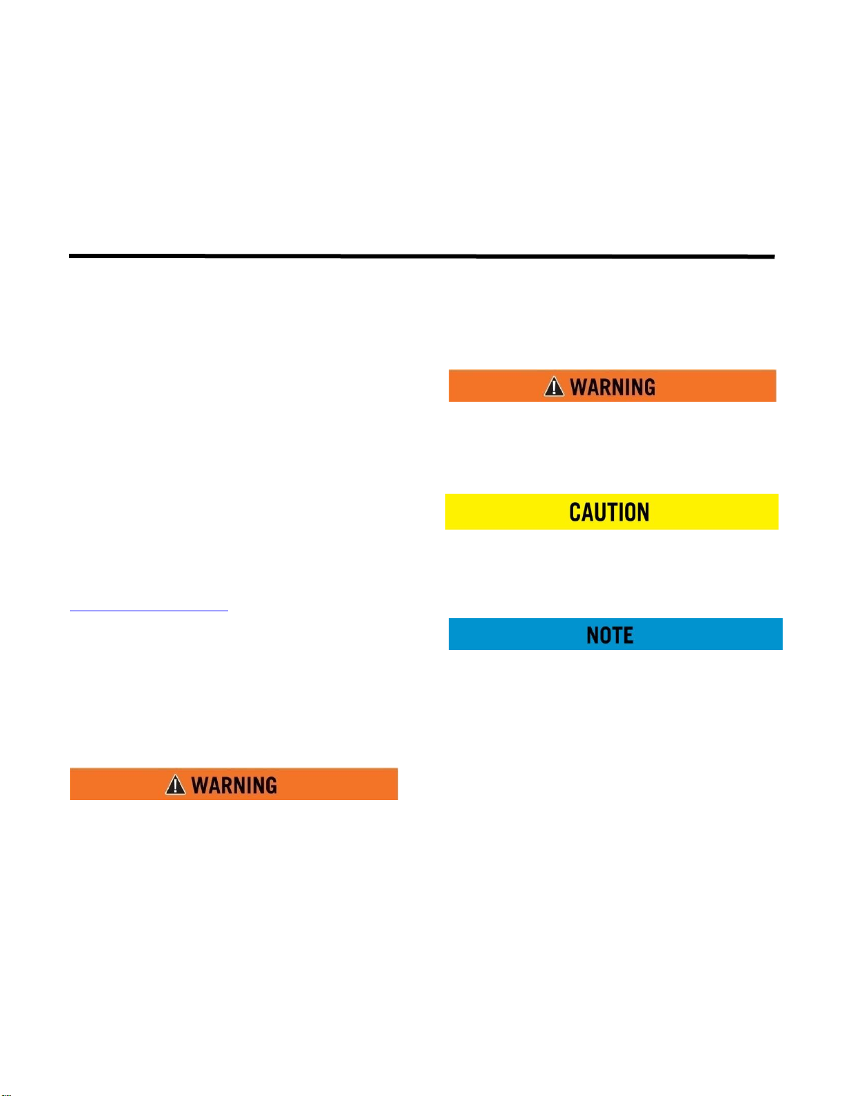
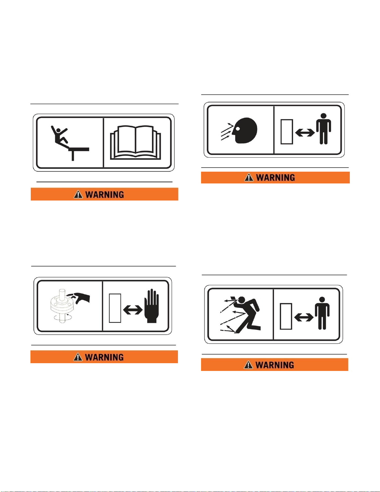
Toxic Gas Hazard (1)
This safety label is located on the side of the tank
and at all water fill entrances.
Cutting or welding operation on the inside of
the tank can cause the accumulation of toxic
gases. Read and understand instructions and
warnings in the Maintenance Manual.
Failure to provide proper ventilation or
breathing apparatus while conducting these
operations may result in serious injury or
death.
Do Not Operate (2)
This safety label is located on the outside of the
front and rear control boxes. (If equipped)
Do not open this control box unless you read
and understand the instructions and warnings
in the Operator and Maintenance Manual.
Failure to follow instructions or heed the
warnings could result in serious injury or
death.
1-2
Page 6
SECTION 1
Definitions and Abbreviations
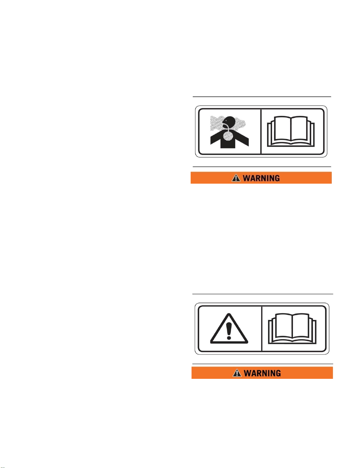
Backing Runover Hazard (3)
This safety label is located on the rear of the tank
and inside the cab.
The vehicle is equipped with a back-up alarm.
Alarm must sound when operating this
vehicle in reverse. Failure to maintain a clear
view in the direction of travel could result in
serious injury or death.
Freezing (4)
This safety label is located on the side of the
tank, at the sump drain, and on the pump.
Drain tank, fill pipe and valve in freezing
weather. Refer to the Operator and
Maintenance Manual for the procedure to
follow.
MMP4-5
13 Feb 2012
Non-Potable (5)
This safety label is located on the side of the tank
and sump drain.
Water held within tank is not potable. Do not
use tank for transport of water intended for
human or animal consumption or serious
injury or death may result.
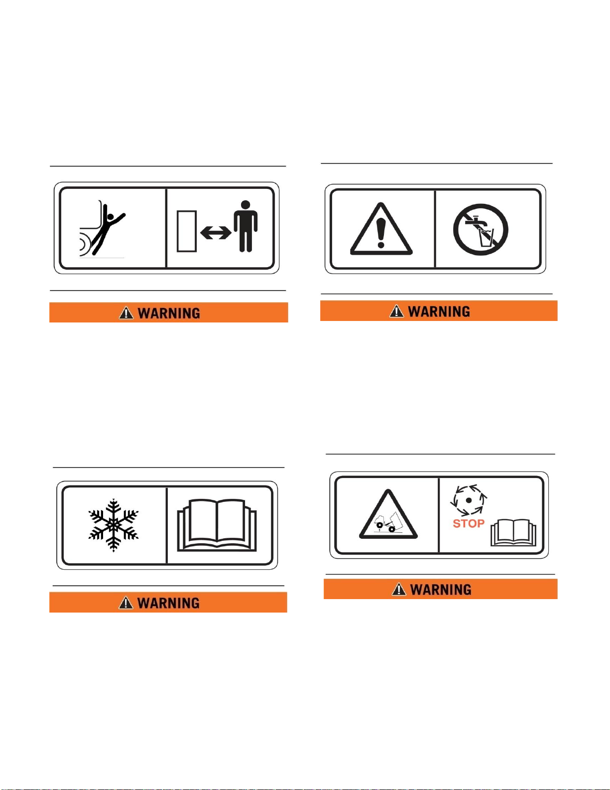
Do Not Hoist While in Motion (6)
This safety label is located inside the cab.
Do not engage hoist cylinders while vehicle is
in motion. Before engaging hoist STOP the
vehicle. Do not engage hoisting cylinders
unless you read and understand the
instructions and warnings in the Operator or
Maintenance Manual. Failure to follow
instructions or heed the warnings will result
in injury or death.
1-3
Page 7
MMP4-5
13 Feb 2012
Definitions and Abbreviations
Fall Hazard (7)
This safety label is located at the top of the front
and rear of the tank.
Do not walk on the top of tank without fall
arrest PPE. Serious injury or death could
occur from a fall.
Rotating Shaft (8)
This safety label is located on the pump.
Do not place your hand or tools within pump
bell while pump is rotating and/or pressure
held within the motor supply hose. Refer to
the Operator and Maintenance Manual for
the procedures to operate and maintain the
pump. Failure to follow proper procedures
could result in serious injury.
SECTION 1
High Pressure Sprayheads (9)
This safety label is located on the spraybar.
Do not operate sprayheads until all personnel
are a safe distance away from the vehicle.
High Pressure Monitor (10)
This safety label is located on top of the cab
control box.
Do not operate the monitor until all personnel
are a safe distance away from the vehicle.
1-4
Page 8

SECTION 1
Definitions and Abbreviations
High Pressure Motor (11)
This safety label is located on the hydraulic
motor.
Hydraulic motor and supply lines contain oil
under high pressure. Improper removal and
repair procedures could cause severe injury.
To remove or repair, instructions in the
Maintenance Manual must be followed.
Confined Space (12)
This safety label is located near water tank
access and fill ports.
Do not enter confined spaces without
following established site specific
procedures. Failure to follow proper safety
procedures will result in serious injury or
death.
MMP4-5
13 Feb 2012
ABBREVIATIONS
BFV – Butterfly Valve
cc – Cubic Centimeters
CCW – Counter Clockwise
CW - Clockwise
fl. oz. – Fluid Ounce
FT - Feet
FPM – Feet Per Minute
GPM – Gallons Per Minute
IN/SQ FT – Inches per Square Feet
KM-H – Kilometers Per Hour
Kg – kilograms
Kpa - Kilopascals
l – liters
lpm – Liters per minute
LT – Left as viewed from the operators
position
facing forward
m - meters
MPH – Miles Per Hour
MTT – Mega Truck Tank
Nm – Newton meters of torque
psi - pounds per square inch
RPM – Revolutions Per Minute
RT – Right as viewed from the operators
position facing forward
SQ FT – Square Feet
VDC – Volts, Direct Current
1-5
Page 9

MMP4-5
13 Feb 2012
SECTION 1
Definitions and Abbreviations
1-6(Blank)
Page 10

Definitions and Abbreviations
1
Discharge Boom
13
Water Pump, Axial, 12”
2
Hinge Pin (2 required)
14
Intake Guard Plate
3
Flange Gasket (2 required)
15
Battery Box
4
Jack Stand (3 required)
16
Hitch Pins, 1” (2 required)
5
Hydraulic Control Valve with handles
17
Coupler, 2 5/16”
6
Control Valve mounting plate
18
Water Pump Gasket, 12”
7
Victaulic Coupling, 12”
19
CAT 3054 Engine assembly
8
Intake Boom
20
Guard, Radiator
9
Tail Light (2 required)
21
Fuel Tank Assembly
10
Fender (1 Right hand)(1 Left Hand)
22
Tire and Rim Assembly
11
Marker Light (2 Red)(4 Amber)
23
Axle Assembly
12
Filter, Hydraulic, 400 psi
MMP 4 GENERAL OVERVIEW
MMP 4 Basic View
MMP4-5
13 Feb 2012
SECTION 1
1-7
Page 11

MMP4-5
1
Discharge sock, tapered
7
Hydraulic Tank Assembly
2
Cylinder, Discharge Boom
8
Cylinder, Inlet Boom
3
Hitch Pin, 1”, Boom Lock (2 required)
9
Marker Light, (2 Red)(4 Amber)
4
Boom, Safety Chain (2 required)
10
Tail Light, (2 required)
5
Safety Chain, Hitch (2 required)
11
Victaulic Coupling, 12”
6
Hydraulic Oil Level Gauge
12
Hydraulic Control Valve with Handles
MMP 4 Basic Rear View
13 Feb 2012
SECTION 1
Definitions and Abbreviations
1-8
Page 12

MMP4-5
FREQUENCY
STEP
FRAME
DAILY
WEEKLY
250 HOURS
OR SEMI
ANNUALLY
500 HOURS
OR
ANNUALLY
1000
HOURS
2000
HOURS
1
Check Frame, Landing gears, Hitch
Assembly and Fenders for cracks and
security.
X
2
Check Axle, Springs, U-Bolts, Spring
mounting hardware for cracks, security and
missing parts.
X
3
Check Safety Chains and restraining
hardware for security and missing parts.
X
4
Check Lug nut torque (80 - 90 ft/lbs), Tire
Pressure and Condition.
BEFORE EVERY MOVEMENT OF MMP4 TRAILER
5
Check Lighting, Hitch assembly, Brakes,
Wheel seals, Hitch Pins, Boom securing
devices, Coupling device and safety Chains.
BEFORE EVERY MOVEMENT OF MMP4 TRAILER
6
Replace Wheel Bearing Lube.
X
STEP
CAT 3054 ENGINE
Refer to the Caterpillar SEBU7276-01 3054B Industrial Engine Manual for Caterpillar
Engine specific maintenance guidelines and parts.
1
Check Engine Oil Level, Engine Fuel Level
and Coolant Level.
X
2
Change Engine Oil and Filter
X
13 Feb 2012
SECTION 2
Scheduled Inspections
Contents
Description ……………………………. 2-1
Frame …..….………….……………….. 2-1
3054B Engine ……..………………..…. 2-1
.
DESCRIPTION
This section establishes scheduled maintenance inspections of a MMP4 powered by a CAT 3054B
diesel engine at the designated frequencies. Performing these inspections will identify potential system
discrepancies and allow preventative maintenance to be performed before a component or system is
rendered totally inoperative.
** NOTE: MMP4’s operated in extremely low quality water environments may require more frequent
inspections.
Hydraulic System ……………………... 2-2
Control System ………………..………. 2-3
2-1
Page 13

MMP4-5
FREQUENCY
STEP
HYDRAULIC SYSTEM
DAILY
WEEKLY
250 HOURS
OR SEMI
ANNUALLY
500 HOURS
OR
ANNUALLY
1000
HOURS
2000
HOURS
1
Check Hydraulic Oil Level.
X
2
Change Hydraulic Oil Filter.
X
3
Change Hydraulic Oil.
X
4
Check Water Pump Lube Reservoirs.
X
5
Grease Suction Bowl Reservoir..
X
6
Check Hydraulic Hoses and Fittings for
Security and Leaks.
X
7
Change Oil in Both water Pump Oil
Reservoirs.
X
8
Check For Hydraulic Oil Leaks
X
9
Check For Water Leaks
X
10
Check Hydraulic Pump for Security and
Leaks.
X
13 Feb 2012
SECTION 2
Scheduled Inspections
2-2
Page 14

MMP4-5
FREQUENCY
STEP
CONTROL SYSTEM
DAILY
WEEKLY
250 HOURS
OR SEMI
ANNUALLY
500 HOURS
OR
ANNUALLY
1000
HOURS
2000
HOURS
1
Check MURPHY Switch for proper
Operation.
X
2
Check Throttle control for Proper Engine
RPM’s.
X
3
Check Hydraulic Control Valve For proper
Operation and Leaks.
X
4
Check Boom Safety Chains for Security and
Function.
X
5
Check Hydraulic Cylinders for Security,
Operation and Leaks.
X
6
Check Main Hydraulic Relief Pressure
Setting. (2000 psi)
X
7
Lube Boom Hinge Pins and Hydraulic
Cylinder Pins.
X
8
Inspect Boom Hinge Flange Gaskets for
Leaks and Damage.
X
9
Check Inlet and Discharge Tubing for
Damage and leaks, to include Discharge
Sock and Victaulic Coupling.
X
13 Feb 2012
SECTION 2
Scheduled Inspections
2-3
Page 15

MMP4-5
13 Feb 2012
SECTION 2
Scheduled Inspections
2-4(Blank
Page 16

MMP4-5
13 Feb 2012
SECTION 3
Special Inspections
Contents
Description ……………………………. 3-1 Storage/Winterization …………………. 3-1
DESCRIPTION
This section contains special inspection
requirements for a specific system after use, an
unusual event or storage.
STORAGE/WINTERIZATION
Entering
1. Remove any exterior dirt, grease and grime
that may trap moisture.
2. Flush all water suction and discharge tubes
(e.g. water pump,).
3. Ensure all water is drained from the tubes
and water pump.
4. Ensure all covers/caps for fluid reservoirs
are in proper operating condition and are
secured to the openings.
5. Fill Fuel tank to capacity, shut fuel shut off
valves at bottom of fuel tank.
6. Check tires for proper inflation.
7. Check Boom retaining hardware, ensure it
is operational and secure.
8. Lubricate all grease points (e.g. Hinge pins,
cylinder pins water pump suction bowl).
9. Check battery fluid level and charge.
10. Disconnect battery cables from battery.
11. Service all engine systems per CAT
SEBU7276-01 service manual.
12. If possible, shelter entire unit from the
elements.
Removing
1. Remove all covers and seals from all
fill/discharge openings and components.
2. Inspect piping for debris that may damage
unit that water will be pumped into.
3. Check to ensure all water pump reservoirs
are filled to the correct level and the fluid is
not contaminated.
4. Remove any exterior dirt, grease and grime
and treat any corrosion.
5. Service all Engine systems per CAT
SEBU7276-01 service manual.
6. Check all fluid levels for condition and
level, replace or adjust as necessary.
7. Check Braking system (if equipped) repair
as necessary.
8. Check safety chains for damage.
9. Check lighting system for proper operation,
repair as necessary.
10. Clean and connect battery cables to battery.
11. Perform ‘Daily’ maintenance checks, repair
as necessary.
12. Perform a full functional check of all MMP
control systems.
3-1
Page 17

MMP4-5
13 Feb 2012
SECTION 3
Special Inspections
3-2(Blank)
Page 18

MMP4-5
A. AXIAL WATER PUMP GROUP, 303910
PART DESCRIPTION
PART NO.
QTY
1. Gasket, 12”
304174
2
2. Grommet
303910-03
2
3. Thrush Collar
303910-17
1
4. Lower Seal
303910-20
1
5. Upper Seal
303910-25
1
6. O-Ring, Bearing, (Lower)
303910-31
2
7. O-Ring, Hydraulic Motor, (Upper)
303910-35
2
B. HYDRAULIC GROUP
PART DESCRIPTION
PART NO.
QTY
1. Cylinder, 12”, Discharge Boom
303923
1
2. Cylinder, 20”, Inlet Boom
303924
1
3. Filter, Hydraulic, 400 psi
304704
2
4. Cap, Hydraulic Tank
302624
1
5. Gauge, Hydraulic Oil Level
304094
1
6. Gasket, Hydraulic Oil Tank
304116
1
7. Oil, Hydraulic, Clarity (35 Gallon Capacity)
Call MEGA
Corp Product
Support for
assistance
35 gal
13 Feb 2012
SECTION 4
Recommended Support Parts
Contents
Description …………………………… 4-1
Axial Water Pump Group ……………. 4-1
Hydraulic Group ……………………… 4-1
Water Piping Group ………………….. 4-2
DESCRIPTION
This section contains a listing of recommended support parts that should be available in the supply
warehouse. Once parts are issued from warehouse stock ensure depleted quantities are replenished to
keep the recommended support parts package at 100%.
The tables are categorized by specific sub system of the MMP. DO NOT FORGET that all MMP’s are
not configured the same and there are some variations in systems due to changes in equipment and
actual production dates. Ensure MMP serial numbers and actual component part numbers are checked
before ordering any parts.
Frame and Suspension Group ………... 4-2
CAT 3054B Group ………………..….. 4-2
Lighting Group ……………………….. 4-3
Notes ………………………………..… 4-4
4-1
Page 19

MMP4-5
C. WATER PIPING (BOOM) GROUP
PART DESCRIPTION
PART NO.
QTY
1. Sock, Down spout, tapered
304196
2
2. Tie Down Strap, 2”
304291
1
3. Pin, Hinge pivot
037627-05
1
4. Neoprene gasket, Boom flange
304117
2
5. Pin, Hitch, 1”
303935
2
6. Chain, 3/8”
355028
6 ft
7. Shackle, 3/8”
355020
4
D. FRAME AND SUSPENSION GROUP
PART DESCRIPTION
PART NO.
QTY
1. Wheel and Tire Assembly
303933
1
2. Hitch pin, 1”
303935
2
3. Chain, 3/8”
355028
4 ft
4. Shackle, 3/8”
355020
2
5. Bearing, Wheel, Inner
304157
2
6. Bearing, Wheel, Outer
304158
2
7. Seal, Wheel Bearing
304159
2
8. Jack stand
037708
1
9. Hitch, 2 5/16 Ball Coupler
304231
1
E. CAT 3054B ENGINE SUPPORT PARTS GROUP
REFER TO SEBU7276-01 INDUSTRIAL ENGINE MANUAL FOR SPECIFIC PARTS AND SERVICE
INFORMATION
PART DESCRIPTION
PART NO.
QTY
1. Filter, Engine Oil
304192
1
2. Filter, Element, Fuel
304188
1
3. Filter, Element, Fuel/Water Separator
304190
1
4. Filter, Element, Air, Primary
304186
1
5. Filter, Element, Air, Secondary
304187
1
6. Seal, Filter, Fuel
304189
1
7. Seal, Filter, Water Separator Base
304191
1
8. Gauge, Fuel Tank
304515
1
9. Cap, Fuel Tank
304091
1
10. Petcock, ¼”
300296
2
13 Feb 2012
SECTION 4
Recommended Support Parts
4-2
Page 20

MMP4-5
F. LIGHTING GROUP
PART DESCRIPTION
PART NO.
QTY
1. Light, Stop/Tail/Turn
302607
2
2. Light, Clearance, Amber
302974
2
3. Light, Clearance, Red
302975
2
4. Light, license plate
304124
1
5. Wiring Harness
304119
1
13 Feb 2012
SECTION 4
Recommended Support Parts
NOTES
4-3
Page 21

MMP4-5
13 Feb 2012
SECTION 4
Recommended Support Parts
NOTES
4-4
 Loading...