

Page 1

MMP4-2
SPECIALTY HAULAGE SOLUTIONS FOR CONSTRUCTION AND MINING
Maintenance Manual
MEGA CORP.®
700 Osuna Rd. N.E. • Albuquerque, NM 87113 • 1-800-345-8889 • 505-345-2661 • Fax 505-345-6190
www.megacorpinc.com
® MEGA Corp., Inc. All Rights Reserved
Page 2

MMP 4-2
5 Nov 2011
TABLE OF CONTENTS
Page
Definitions and Abbreviations ……………………………………….………………..….. 1-1
MEGA Mobile Pump (MMP 4) ...……………………………….……………………….. 2-1
Hydraulic Control System ………………………………….…………………………….. 3-1
Basic Hydraulics System …………………………………..……….………….………… 4-1
Water Pump Assembly ..…………………………..…………….……………….………. 5-1
Axle and Suspension ………………………………………….………………….………. 6-1
Frame and Booms ………..………………………………………………………….….… 7-1
Scheduled Inspections ...….…………….………………………….……………….……. 8-1
Special Inspections ………..……………………………………….………………….….. 9-1
Recommended Spare Parts ………………………………………………………….….… 10-1
Appendix ……………………………………………………………….………………... 11-1
A
Page 3

MMP 4-2
5 Nov 2011
TABLE OF CONTENTS
B(Blank)
Page 4

SECTION 1
Definitions and Abbreviations
Contents
Warning, Caution & Notes ………………. 1-1
Shall, Will, Should and May ……………. 1-1
Safety Messages ………………………… 1-2
MANUAL USAGE
This technical manual only contains
information required to safely maintain the
MMP-4 powered by a CAT 3054B diesel
engine. See the CAT 3054B Engine
Maintenance and Operators Safety Manual for
specific engine system information and
maintenance procedures. The exact location of
the hazards and description of the hazards are
reviewed in this section. All personnel
working on or operating the machine must
become familiarized with all the safety
messages.
If your system is not covered in this manual or
are having difficulties please contact the
MEGA Corp. Product Support Group at:
Toll free US 1-800-345-8889
Direct 1-505-345-2661
or visit our website at www.megacorpinc.com
for more detailed contact information.
Due to the nature of these processes, ensure
that all safety information, warnings and
instructions are read and understood before any
operation or any maintenance procedures are
performed. This service function takes place
with heavy components and at moderate
heights, ensure proper safety procedures are
maintained when performing this service.
Failure to use and maintain proper safety
MMP 4-2
5 Nov 2011
Abbreviations ………………………..… 1-5
MMP 4 General Overview …………….. 1-6
WARNING, CAUTIONS AND
NOTES
The following definitions are found throughout
the manual and apply as follows:
Operating procedures and techniques, which
could result in personal injury and/or loss of
life if not carefully followed.
Operating procedures and techniques, which
could result in damage to equipment if not
carefully followed.
Operating procedures and techniques that are
considered essential to emphasis.
USE OF SHALL, WILL, SHOULD AND
MAY
Shall and Will – Used when application of a
procedure is mandatory.
Should – Used when application of a
procedure is recommended.
May - Used to indicate an acceptable or
suggested means of accomplishment.
1-1
Page 5
MMP 4-2
5 Nov 2011
SECTION 1
Definitions and Abbreviations
SAFETY MESSAGES
There are several specific safety messages on
this machine. The exact location of the hazards
and description of the hazards are reviewed in
this section. All personnel working on or
operating the machine must become familiarized
with all the safety messages.
Make sure that all of the safety messages are
legible. Clean the safety messages or replace the
safety messages in you cannot read the words.
Replace the illustrations if the illustrations are
not legible. When you clean the safety
messages, use a cloth, water and soap. Do not
use solvent, gasoline or other harsh chemicals to
clean the safety messages. Solvents, gasoline or
harsh chemicals could loosen the adhesive that
secures the safety messages. Loose adhesive
will allow the safety messages to detach.
Replace any safety message that is damaged or
missing. If a safety message is attached to a part
that is replaced, install a new safety message on
the replacement part.
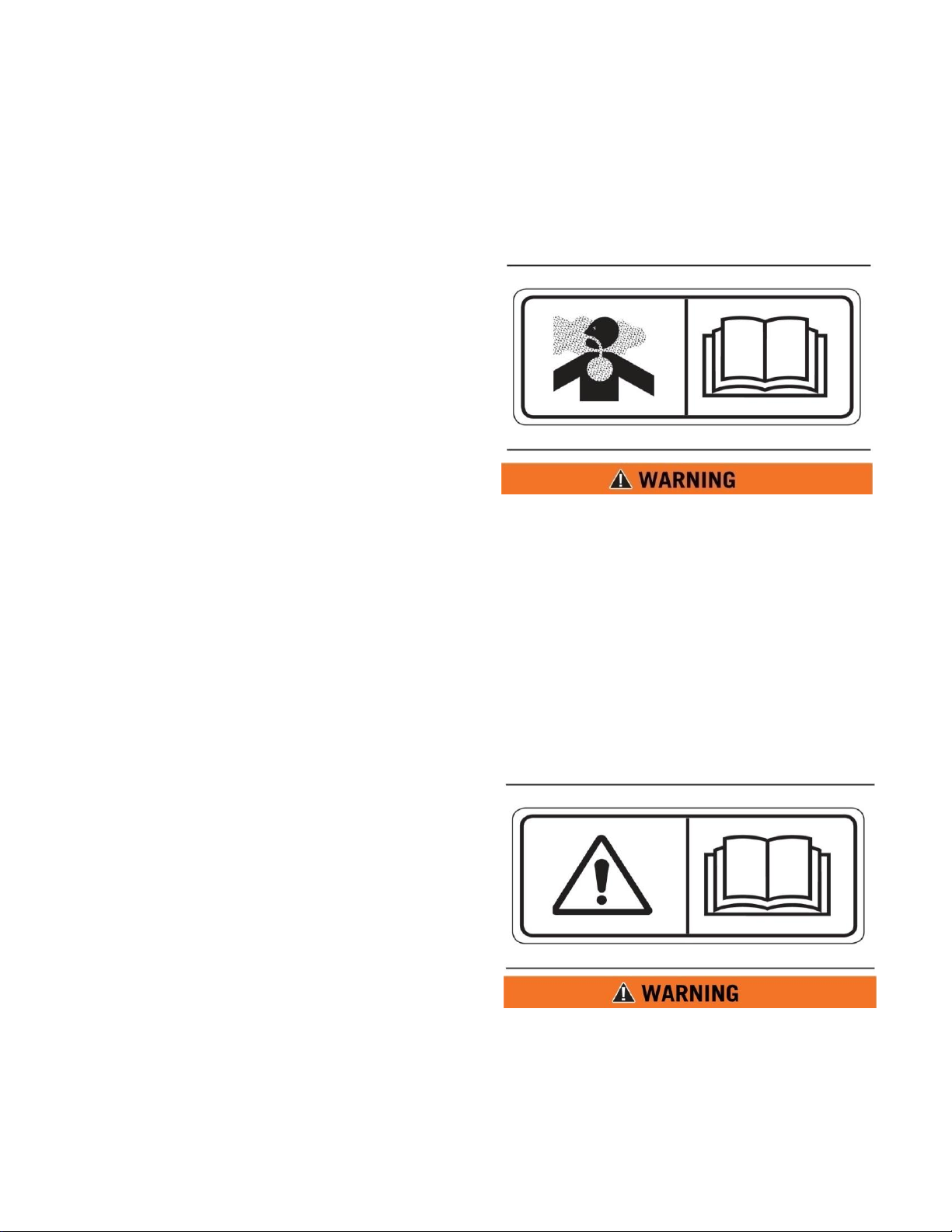
Toxic Gas Hazard (1)
This safety label is located on the side of the tank
and at all water fill entrances.
Cutting or welding operation on the inside of
the tank can cause the accumulation of toxic
gases. Read and understand instructions and
warnings in the Maintenance Manual.
Failure to provide proper ventilation or
breathing apparatus while conducting these
operations may result in serious injury or
death.
Do Not Operate (2)
This safety label is located on the outside of the
front and rear control boxes. (If equipped)
Do not open this control box unless you read
and understand the instructions and warnings
in the Operator and Maintenance Manual.
Failure to follow instructions or heed the
warnings could result in serious injury or
death.
1-2
Page 6
SECTION 1
Definitions and Abbreviations
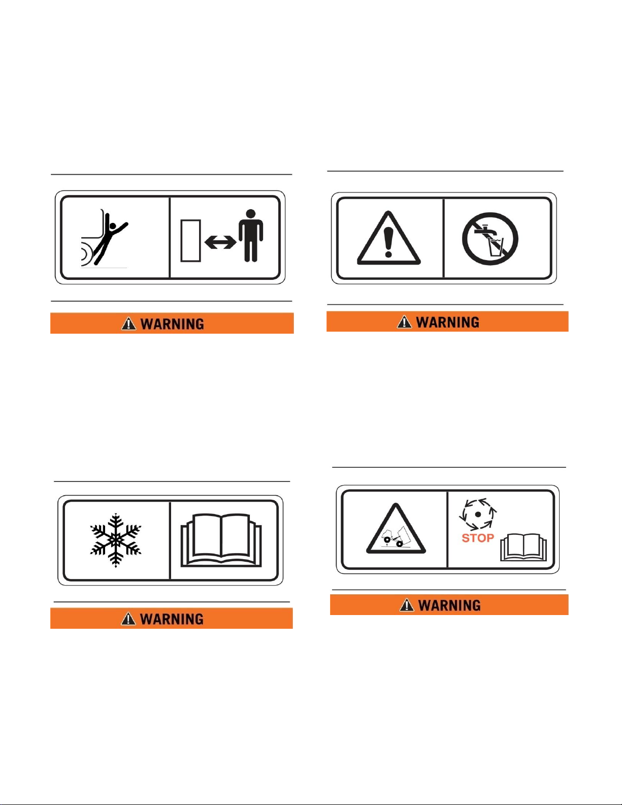
Backing Runover Hazard (3)
This safety label is located on the rear of the tank
and inside the cab.
The vehicle is equipped with a back-up alarm.
Alarm must sound when operating this
vehicle in reverse. Failure to maintain a clear
view in the direction of travel could result in
serious injury or death.
Freezing (4)
This safety label is located on the side of the
tank, at the sump drain, and on the pump.
Drain tank, fill pipe and valve in freezing
weather. Refer to the Operator and
Maintenance Manual for the procedure to
follow.
MMP4-5
5 Nov 2011
Non-Potable (5)
This safety label is located on the side of the tank
and sump drain.
Water held within tank is not potable. Do not
use tank for transport of water intended for
human or animal consumption or serious
injury or death may result.
Do Not Hoist While in Motion (6)
This safety label is located inside the cab.
Do not engage hoist cylinders while vehicle is
in motion. Before engaging hoist STOP the
vehicle. Do not engage hoisting cylinders
unless you read and understand the
instructions and warnings in the Operator or
Maintenance Manual. Failure to follow
instructions or heed the warnings will result
in injury or death.
1-3
Page 7
MMP 4-2
5 Nov 2011
SECTION 1
Definitions and Abbreviations
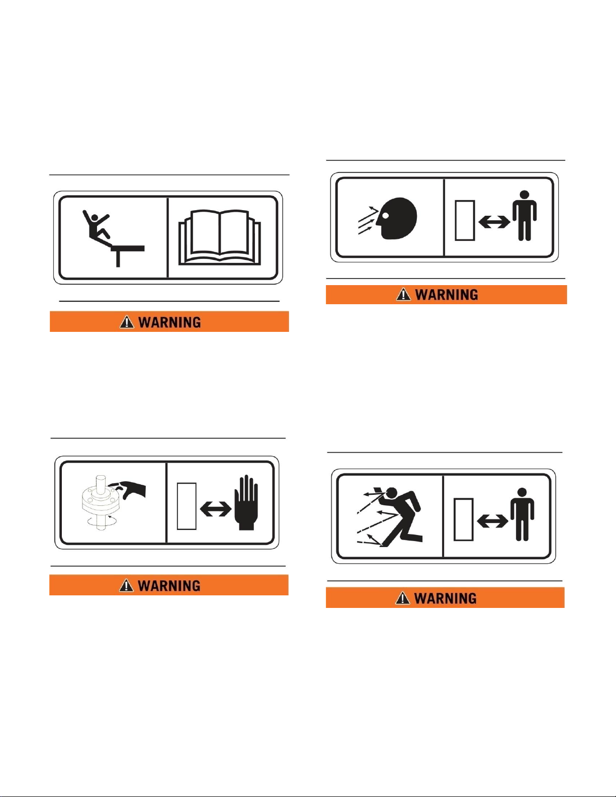
Fall Hazard (7)
This safety label is located at the top of the front
and rear of the tank.
Do not walk on the top of tank without fall
arrest PPE. Serious injury or death could
occur from a fall.
Rotating Shaft (8)
This safety label is located on the pump.
Do not place your hand or tools within pump
bell while pump is rotating and/or pressure
held within the motor supply hose. Refer to
the Operator and Maintenance Manual for
the procedures to operate and maintain the
pump. Failure to follow proper procedures
could result in serious injury.
High Pressure Sprayheads (9)
This safety label is located on the spraybar.
Do not operate sprayheads until all personnel
are a safe distance away from the vehicle.
High Pressure Monitor (10)
This safety label is located on top of the cab
control box.
Do not operate the monitor until all personnel
are a safe distance away from the vehicle.
1-4
Page 8
SECTION 1
Definitions and Abbreviations
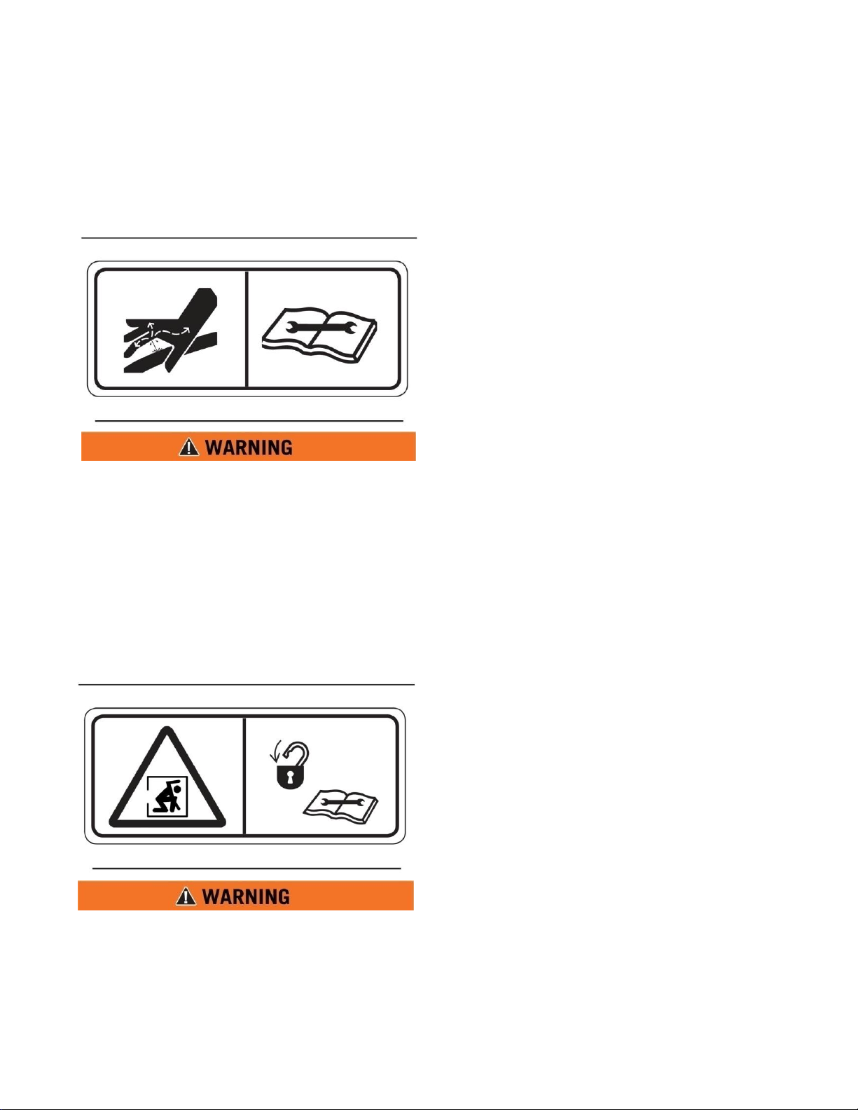
High Pressure Motor (11)
This safety label is located on the hydraulic
motor.
Hydraulic motor and supply lines contain oil
under high pressure. Improper removal and
repair procedures could cause severe injury.
To remove or repair, instructions in the
Maintenance Manual must be followed.
Confined Space (12)
This safety label is located near water tank
access and fill ports.
Do not enter confined spaces without
following established site specific
procedures. Failure to follow proper safety
procedures will result in serious injury or
death.
MMP 4-2
5 Nov 2011
ABBREVIATIONS
BFV – Butterfly Valve
cc – Cubic Centimeters
CCW – Counter Clockwise
CW - Clockwise
fl. oz. – Fluid Ounce
FT - Feet
FPM – Feet Per Minute
GPM – Gallons Per Minute
IN/SQ FT – Inches per Square Feet
KM-H – Kilometers Per Hour
Kg – kilograms
Kpa - Kilopascals
l – liters
lpm – Liters per minute
LT – Left as viewed from the operators
position facing forward
m - meters
MPH – Miles Per Hour
MTT – Mega Truck Tank
Nm – Newton meters of torque
psi - pounds per square inch
RPM – Revolutions Per Minute
RT – Right as viewed from the operators
position facing forward
SQ FT – Square Feet
VDC – Volts, Direct Current
1-5
Page 9
MMP 4-2
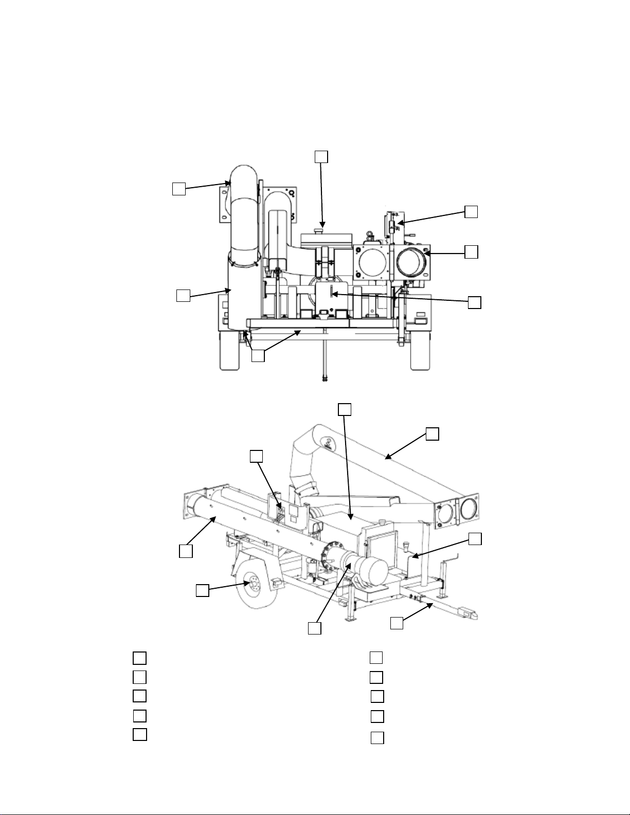
MMP 4 GENERAL OVERVIEW
DISCHARGE BOOM
5
DISCHARGE SOCK
3
1
2
4
INLET BOOM
WATER PUMP
HYDRAULIC CONTROL VALVE
6
7
HITCH ASSEMBLY
3054 CAT ENGINE ASSEMBLY
8
HYDRAULIC TANK
9
50 GALLON FUEL TANK
10
AXLE AND SUSPENSION
SIDE
VIEW
1
2
3 4 7 6 9
10
REAR
VIEW
1
2
4 5 7 8 10
5 Nov 2011
SECTION 1
Definitions and Abbreviations
1-6
Page 10
SECTION 2
MMP-4 Overview
Contents
Description ……………………………… 2-1
Inspection ……………………………..... 2-1
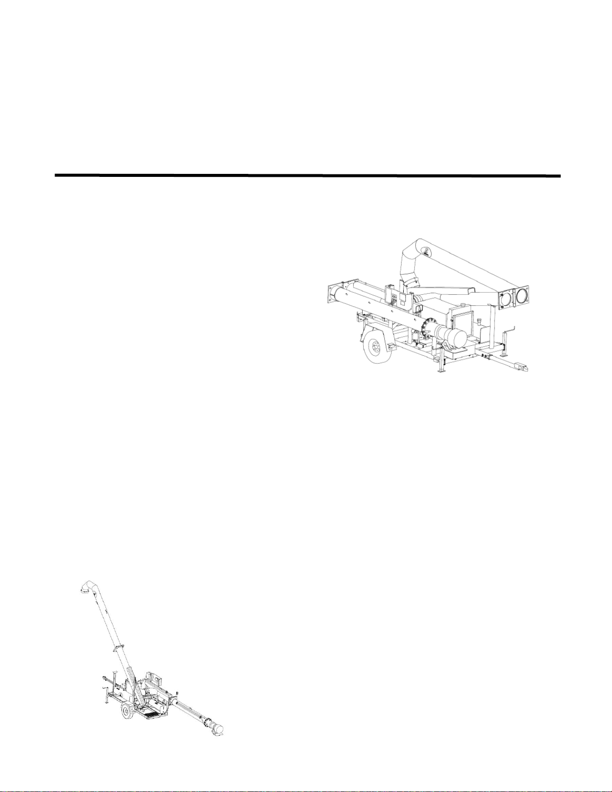
DESCRIPTION
The MEGA Mobile Pump is a towable water
lifting station. The MMP 4 may be towed by a
vehicle capable of at least a 6,000 pound (2,725
kg) towing capacity, 1,000 pound (450 kg)
tongue weight and equipped with the
appropriate weight rated Class IV trailer hitch
with a 2 5/16” ball. The MMP 4 can be
transported to a water holding pond and be set
up by 1 individual. MMP 4’s are a self
contained pumping station fitted with a
hydraulically driven 12” axial water pump that
has the potential to lift water 25’ (7.62 meters)
from pump level to fill water distribution
equipment (maximum height, 17’ [5.2 meters]
above ground level). MMP 4’s are equipped
with: hydraulically lifted inlet and discharge
booms with safety retaining chains and travel
locking devices, DOT rated lighting, 16” load
range ‘E’ on-highway trailer tires, a fold away
hitch with safety chains, a vacuum break with
an anti-siphon discharge sock on the discharge
boom, 23 gallon (87 liter) hydraulic oil tank
filled with Chevron Clarity AW 46 hydraulic
oil, a gear type hydraulic pump driven by a
Caterpillar 3054B series diesel engine and a 50
gallon (190 liter) capacity diesel fuel tank
equipped with shut off valves.
MMP 4-2
5 Nov 2011
Repair …………..............………….......... 2-2
The MMP 4 needs a minimum of 2.5’ (0.762
meters) of water above the inlet of the water
pump for proper operation.
INSPECTION
1. Inspect MMP 4 exterior paint for damage
and corrosion.
2. Inspect piping for damage and leaks.
3. Inspect frame, landing gear and suspension
for damage and missing parts.
4. Inspect engine assembly for loose, missing,
damaged or leaking parts.
5. Inspect all hydraulic hoses and couplings
for security, damage and leaking.
6. Inspect fuel, engine oil, anti freeze and
hydraulic oil for contamination and proper
level.
7. Inspect lighting, lug nuts, fenders and hitch
safety equipment for operation, damage and
missing parts.
8. Inspect electrical system for corrosion,
damage and missing parts.
2-1
Page 11

MMP 4-2
5 Nov 2011
SECTION 2
MMP-4 Overview
REPAIR
Paint
Remove corrosion, prime and paint as required.
Engine Fluid Levels and Inspections
Adjust, repair or service according to CAT
SEBU7276-01 manuals for engine service
schedule.
Leaks
1. Remove paint and corrosion from suspected
area.
2. Prep surface to be welded, weld over leak.
3. Prime and paint over weld.
4. Tighten or replace damaged or leaking
component.
Lighting
Repair as required to maintain DOT
compliance.
Missing parts
Contact MEGA Corp Parts sales for assistance.
Structure
Contact the MEGA Corp. Product Support
Group at:
Toll free US 1-800-345-8889
Direct 1-505-345-2661
or visit our website at www.megacorpinc.com
for more detailed contact information or
assistance on major structural repairs.
2-2
Page 12
SECTION 3
Control
Function
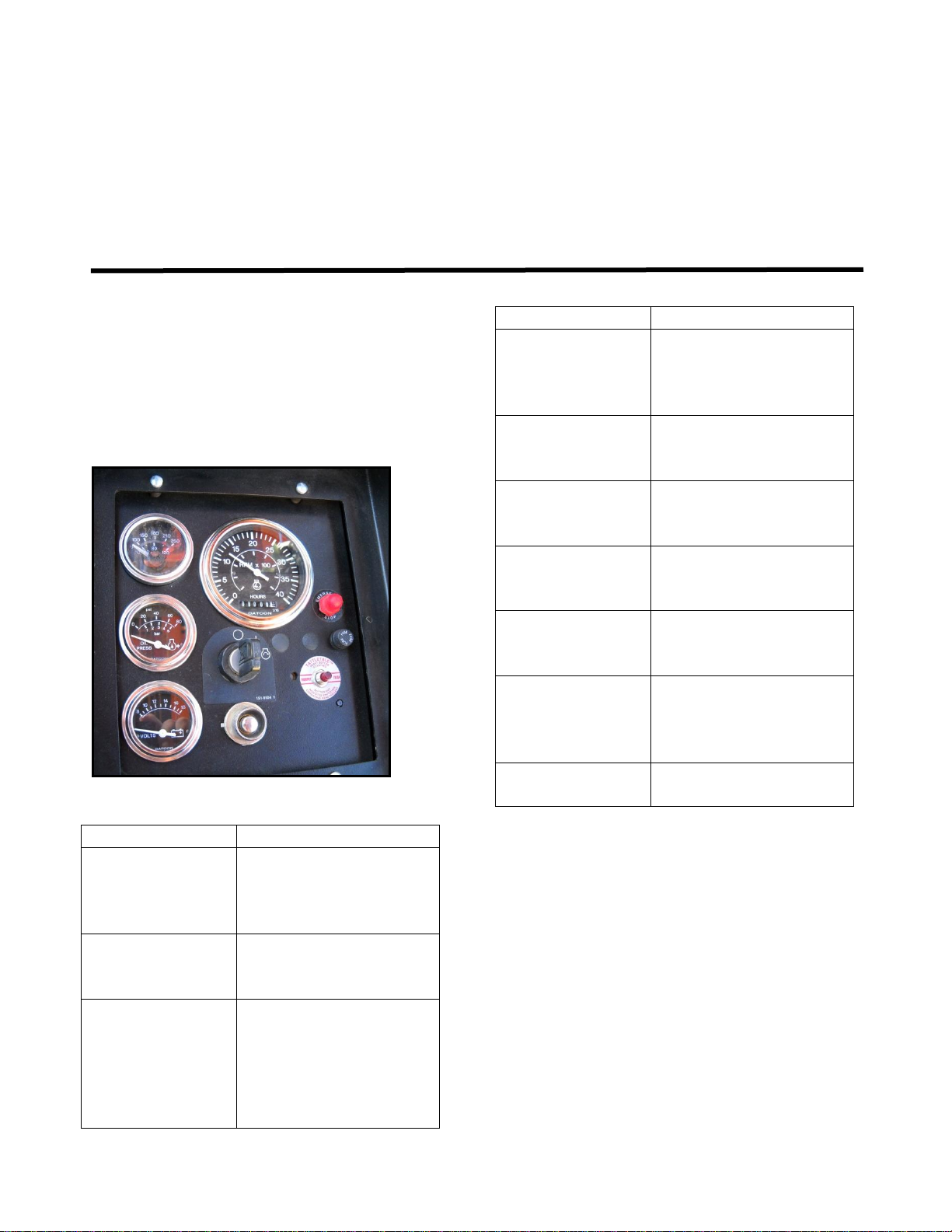
IGNITION
SWITCH WITH
KEY
Controls engine
electrical system to start,
run and shut down
engine.
GLOW PLUG
BUTTON
Operates the cold
weather starting aid
system.
MURPHY
SWITCH
A magnetic switch that
shuts the engine down in
the event of: low engine
oil pressure and/or over
heating of the engine
cooling system.
Control
Function
SYSTEM FUSE
Protects the engine
control electrical system
in the event of an
electrical short circuit.
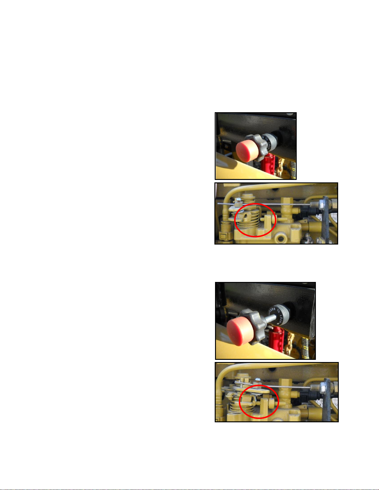
EMERGENCY
STOP BUTTON
Disengages the Murphy
switch to shut engine
down.
THROTTLE
CONTROL
Controls and locks
engine throttle lever to a
fixed RPM.
BATTERY
VOLTAGE
GAUGE
Displays electrical
system voltage.
ENGINE OIL
PRESSURE
GAUGE
Displays engine oil
pressure.
ENGINE
COOLANT
TEMPERATURE
GAUGE
Displays engine coolant
temperature.
ENGINE
TACHOMETER
Displays engine RPM’s.
Engine Control System
Contents
Description ……………………………. 3-1
Inspection ……………………………... 3-2
DESCRIPTION
The Engine control system consists of: A
Control box with lockable cover, Ignition
switch with key, Glow plug button, Murphy
switch, System fuse, Emergency stop button,
Throttle control, Battery voltage gauge, Engine
oil pressure gauge, Engine coolant temperature
gauge and an Engine Tachometer.
The control functions operate as follows:
MMP 4-2
5 Nov 2011
Repair …………………………………. 3-2
INSPECTION
1. Inspect control box and cabling for security,
condition and mounting.
2. Inspect switches, gauges and throttle
control for security, damage and
operational condition.
3-1
Page 13

MMP 4-2
5 Nov 2011
SECTION 3
Engine Control System
REPAIR
Switch Replacement
1. Remove power to the engine control.
2. Remove engine control face plate to gain
access to the switch.
3. Mark wiring on old switch before removal
to ensure correct wiring configuration is
maintained.
4. Remove old switch and replace with the
same type of switch.
5. Install wiring on new switch as previously
marked.
6. Install engine control face plate in control
box.
7. Apply power to the engine control and
perform functional check of the newly
installed switch.
Indicator Gauge Replacement
1. Remove power to the engine control.
2. Remove engine control face plate to gain
access to gauge and wiring.
3. Mark wiring on old gauge before removal
to ensure correct wiring configuration is
maintained.
4. Remove old gauge and replace with the
same type of gauge.
5. Install wiring on new gauge as previously
marked.
6. Install engine control face panel in control
box
7. Apply power to the engine control and
perform functional check of newly installed
indicator gauge.
Engine Tachometer Replacement
1. Remove power to the engine control.
2. Remove engine control face plate to gain
access to the backside of the tachometer.
3. Mark wiring on old tachometer before
removal to ensure correct wiring
configuration is maintained.
4. Remove old tachometer and replace with
the same type tachometer.
5. Installed wiring on new tachometer as
previously marked.
6. Install engine control plate in control box.
7. Apply power to engine control and perform
functional check of newly installed
tachometer.
Throttle Control replacement
1. Remove power to the engine and engine
Control system.
2. Loosen cable locking screw on throttle
lever on fuel injection pump.
3. Remove cable jam nut on lever side of the
fuel pump mounting bracket.
4. Remove cable jam nut on throttle adjusting
end of cable.
5. Remove cable assembly.
3-2
Page 14
SECTION 3
Engine Control System
6. Install new throttle cable assembly in
mounting bracket.
7. Thread jam nut on throttle cable adjusting
end behind mounting bracket.
8. Route throttle cable to the fuel pump cable
mounting bracket.
9. Run cable through fuel pump mounting
bracket.
10. Install jam nut on fuel pump throttle lever
side of bracket.
11. Insert throttle cable in the pivot on the
throttle lever of the fuel pump.
12. Ensure throttle cable and fuel pump throttle
lever is in the idle position.
13. Secure the throttle cable locking screw on
the new cable.
14. Ensure the new throttle cable is routed
away from moving parts.
15. Ensure throttle cable is secure.
16. Check operation of newly installed cable
for smooth operation.
MMP 4-2
5 Nov 2011
17. Ensure newly installed throttle cable allows
engine throttle lever to fully contact the
LOW idle stop.
18. Ensure the newly installed throttle cable
allows engine throttle to fully contact the
HIGH idle stop.
3-3
Page 15

MMP 4-2
5 Nov 2011
SECTION 3
Engine Control System
19. Place throttle control cable in the low idle
position.
20. Apply power to engine control box and
engine.
21. Ensure hydraulic ball valve at hydraulic
tank is OPEN.
22. Perform functional check to ensure proper
engine low and high idle RPMs. If engine
RPMs are out of specified range, check
throttle cable adjustment again and refer to
CAT SEBU7276-01 manual for correct
RPM specifications and adjustment
procedures.
3-4
Page 16
SECTION 4
Basic Hydraulics System
Contents
Description …………………………..... 4-1
Hydraulic Tank………………………….. 4-1
Hydraulic Pump………………………… 4-2
Hydraulic Control Valve……………...... 4-2
Water Pump Hydraulic Drive Motor .... 4-2
Hydraulic Cylinders ………………....... 4-3
DESCRIPTION
The MMP 4 hydraulic system originates at a
hydraulic pump coupled to a CAT 3054B
Diesel engine. The system draws hydraulic oil
from a hydraulic tank mounted at the rear of the
MMP 4 frame through a inlet screen inside of
the tank and a shut off valve on the outside of
the tank. The hydraulic pump moves the oil to
a hydraulic control valve mounted to the right
side of the unit. The control valve diverts and
regulates the oil flow and pressure through the
MMP 4 system. The Hydraulic control valve is
used to control the raising and lowering of the 2
hydraulic cylinders attached to the inlet and
discharge booms. The hydraulic control valve
also controls the hydraulic drive motor inside
of the water pump at the end of the inlet boom,
this control feature is equipped with a detent to
allow the lever to stay in the ON position
during water pump operation and is equipped
with a pressure relief valve to protect against
over pressurization of the hydraulic system.
The return hydraulic oil is passed through a
hydraulic oil filter, oil cooler then a diffuser
mounted inside of the hydraulic oil tank.
MMP 4-2
5 Nov 2011
Hydraulic Oil Filter.……………….….. 4-3
Hydraulic Oil Cooler……………….…. 4-4
Hydraulic Hoses ………………….….. 4-4
Inspection ……………………………... 4-5
Repair ……………………………….… 4-7
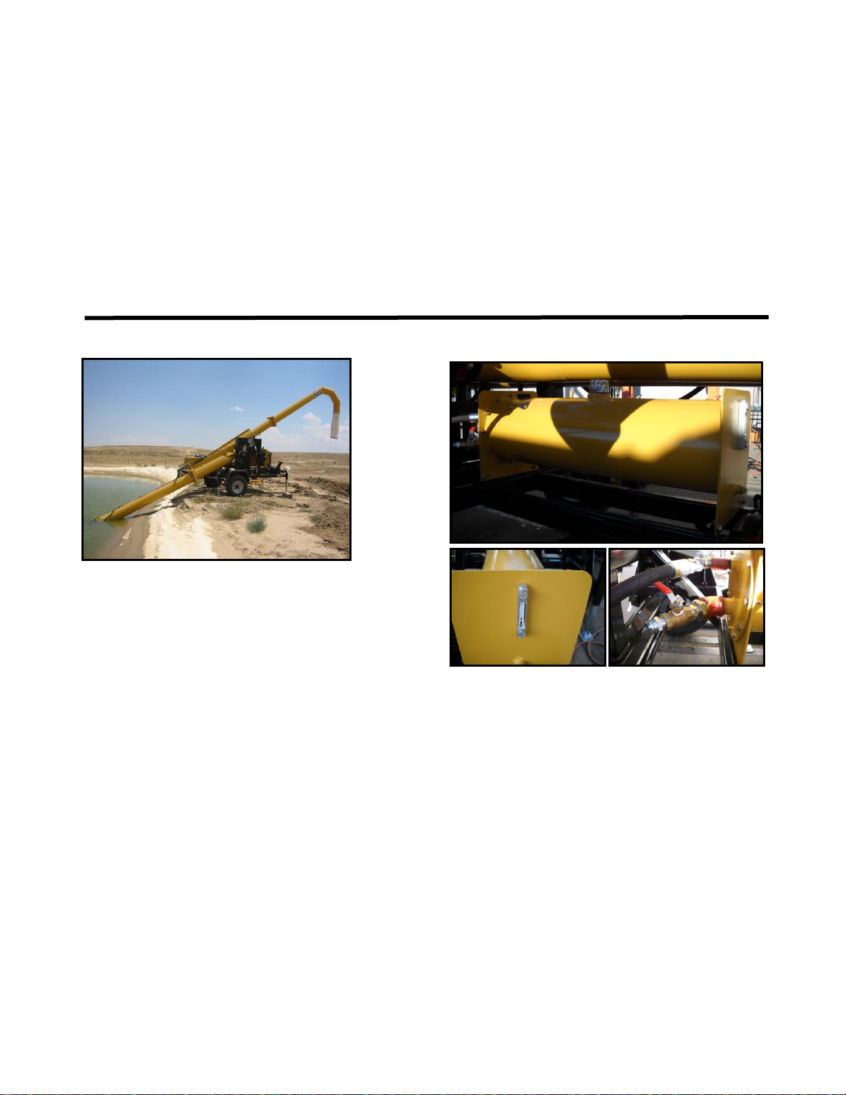
HYDRAULIC TANK ASSEMBLY
The hydraulic tank consists of an inlet screen,
return oil diffuser, internal baffle, shut off
valve, oil level sight gauge, reservoir cap and
breather. The system draws oil from the
bottom of the tank through an inlet screen to
pre-filter the oil. The shut off valve holds the
oil inside of the tank when servicing the
hydraulic system. The sight gauge is used as a
visual indicator of the hydraulic oil quality and
quantity. The Internal baffle allows for oil
movement with in the tank to evenly distribute
the return oil trough out the reservoir. The
return diffuser inside of the hydraulic tank just
below the normal oil level reduces the potential
for hydraulic oil foaming in the tank. The
reservoir cap and breather allow filling of the
hydraulic tank and prevent dirt and debris from
entering the hydraulic system.
4-1
Page 17

MMP 4-2
5 Nov 2011
SECTION 4
Basic Hydraulics System
HYDRAULIC PUMP
The hydraulic pump is coupled to the flywheel
end of the engine. The hydraulic pump moves
the oil through the system to generate flow and
pressure needed to operate the water pump and
boom cylinders. The pump draws oil from the
hydraulic tank and moves it to the hydraulic
control valve.
HYDRAULIC CONTROL VALVE
The hydraulic control valve directs and
regulates the hydraulic pumps oil flow. The
valve operates the boom lifting cylinders by
pressurizing the rod end of the cylinder to make
the booms move up (Cylinder retract). To
lower the booms the valve opens to allow the
oil to return to the hydraulic filter through a
metering control that controls the speed of the
cylinder movement. The hydraulic drive motor
for the water pump portion of the control valve
is equipped with a detent to allow the valve
spool to stay in an open position when the lever
is moved to the ON position for normal water
pump operation. When this lever is moved to
OFF it will shut off hydraulic oil flow to the
water pump drive motor. The hydraulic control
valve is fitted with a pressure regulator that
limits the maximum pressure of the hydraulic
system to 2,100 psi (14,450 kpa). The excess
oil flow is diverted to the hydraulic oil filter.
When the control valves are in the neutral
position, all of the hydraulic oil by-passes
through the control valve to the return
hydraulic oil filter.
WATER PUMP HYDRAULIC
DRIVE MOTOR
The hydraulic drive motor is coupled to the
water pump drive shaft inside the water pump.
The drive motor is controlled by the hydraulic
control valve, water pump spool. When the
lever is moved to the ON position the fluid is
directed to the drive motor causing the water
pump impeller to rotate, moving water up the
inlet boom.
4-2
Page 18

SECTION 4
Basic Hydraulics System
MMP 4-2
5 Nov 2011
HYDRAULIC CYLINDERS
The 2 hydraulic cylinders are used for lifting
the inlet and discharge booms to either the
‘stow/travel’ position or to the ‘fill’ position.
When the boom control lever is operated in the
‘UP’ position the pressurized oil retracts the
cylinder and lifts the boom. The speed of the
lifting is controlled by metering valves attached
to the hydraulic control valve. There are safety
chains at each cylinder to prevent any
unwanted movement in the boom when it is
filled with water and as a safety precaution in
case the control valve lever is operated
accidentally. The cylinder operates in the
boom down mode by moving the control valve
lever to the ‘DOWN’ position, the weight of
the boom makes the cylinder extend. The
speed of the downward motion is controlled by
a fluid metering valve attached to the hydraulic
cylinder that restricts the fluid exiting the
cylinder causing a slow, controlled lowering of
the booms.
HYDRAULIC FILTER
The spin on hydraulic oil filter is in the return
to tank hydraulic circuit. All hydraulic oil
passing through the system passes through the
filter prior to the hydraulic oil cooler. The
filter is rated at 400 psi (2,758 kpa) and has a
provision for the cylinder lower plumbing. The
filter is rated at 10 microns. The filter housing
has a built in bypass valve to bypass the filter
element when the inlet pressure is too high or
the filter becomes restricted.
4-3
Page 19

MMP 4-2
5 Nov 2011
SECTION 4
Basic Hydraulics System
HYDRAULIC OIL COOLER
The hydraulic oil cooler is attached to the front
of the engine radiator. The engine cooling fan
draws cool air through the oil cooler lowering
the oil temperature. The oil cooler is in the
return to tank hydraulic circuit. Built into the
oil cooler is a bypass valve that allows oil to
bypass the cooler if the return oil pressures are
too great (e.g; when the hydraulic oil is cold).
The oil cooler and engine coolant radiator are
protected by a steel mesh guard to prevent
damage to the cooler and radiator.
HYDRAULIC HOSES
The MMP-4 is equipped with hydraulic hosing
to convey the hydraulic oil pressure and flow to
components that are operated by the hydraulic
control valve. These hoses are sized according
to the volume and pressure requirements of the
component. The hydraulic drive motor for the
water pump utilizes a 1” (-16) hose to direct the
volume of oil required to turn motor that drives
the impeller of the water pump at the rated
speed. The hydraulic cylinder hoses require a
smaller volume of fluid and do not require as
large of a hose. The makeup oil requirement
for the lift cylinders (when the booms move
down) are low pressure and low volume. The
suction side of the hydraulic pump requires
suction rated hydraulic hose, this prevents the
hose from collapsing under suction loads.
4-4
Page 20

SECTION 4
OPEN
CLOSED
Basic Hydraulics System
INSPECTION
Hydraulic tank assembly
1. Inspect hydraulic oil tank for security,
damage, leaks.
2. Check hydraulic oil level and quality. The
level should be between 80% and 90% of
the level visible in the sight glass and clear.
3. Check hydraulic tank filler cap, breather
and bolt on end cover for security, damage
and leaks.
4. Check hydraulic hose fittings and shut off
valve, ensure shut off valve is open.
5. Check tank mounting bolts, ensure the bolts
are tight.
MMP 4-2
5 Nov 2011
Hydraulic Pump
1. Inspect hydraulic pump, adapter and hosing
for vibrations, unusual noises, security,
damage and leaks.
Hydraulic Control Valve
1. Check hydraulic control valve mounting for
security, damage and leaks.
2. Check control valve levers for ease of
operation, security, damage and missing
parts.
3. Check control valve fittings and metering
valves for security, damage and leaks.
4. Check pressure regulator for proper relief
pressure (2,100 psi/14,450 kpa), security
and leaks.
4-5
Page 21

MMP 4-2
5 Nov 2011
SECTION 4
Basic Hydraulics System
Water Pump Hydraulic Drive Motor
1. Check water pump drive motor fittings for
security, damage and leaks.
2. Check for an oily film on water surface
(indications of hydraulic oil leak below the
surface of the water). If water pump is
submerged.
3. Check for oil residue inside of the inlet to
the water pump. If water pump is in the
travel position.
Hydraulic Cylinders
1. Check hydraulic cylinders for security,
damage and leaks.
2. Check hydraulic cylinder safety chains for
security, missing parts and damage.
3. Check hydraulic hoses and metering valves
for security, damage and leaks.
4. Check for proper operation and alignment.
Hydraulic filter assembly
1. Inspect hydraulic oil filter mounting for
security and damage.
2. Check hydraulic filter for leaks and
damage.
3. Check hydraulic filter assembly hose fitting
adapters for security and leaks.
Hydraulic Oil Cooler assembly
1. Check hydraulic oil cooler and radiator
guard for security and damage.
2. Check hydraulic oil cooler and fittings for
leaks.
3. Check hydraulic oil cooler for blockage and
debris that may interfere with proper
cooling of oil passing through cooler
assembly.
4-6
Page 22

SECTION 4
Basic Hydraulics System
REPAIR
Hydraulic tank assembly
1. Repair, secure or adjust as required.
Hydraulic Pump
1. Repair or replace as required.
Hydraulic Control Valve
1. Repair, adjust or replace as required.
2. To set hydraulic relief pressure, install a 0 –
3,000 psi (0 – 21,000 kpa) pressure gauge
on the test fitting located on the retract hose
(RAISE) for the inlet boom cylinder.
3. With the engine operating at high idle,
operate the inlet boom UP lever and
observe the reading on the pressure gauge.
MMP 4-2
5 Nov 2011
4. If the hydraulic oil pressure is not within
the specifications, adjust the pressure
regulator cartridge as follows:
a. To increase the pressure, loosen the
lock nut on the regulator stem and
screw in the stem clockwise (CW) until
the pressure is at 2,100 psi (14,450
kpa), tighten lock nut on stem.
b. To reduce the pressure, loosen the lock
nut on the regulator stem and unscrew
the stem counter clockwise (CCW) until
the proper pressure is obtained, tighten
lock nut on stem.
c. Recheck hydraulic pressure.
d. Shut unit off.
e. Remove pressure gauge from test port.
4-7
Page 23

MMP 4-2
Set Screw
Index Marks
5 Nov 2011
SECTION 4
Basic Hydraulics System
Water Pump Hydraulic Drive Motor
1. Repair or replace as required.
Hydraulic Cylinders
1. Repair or replace as required.
Hydraulic Cylinder Speed Control Valve
1. If the hydraulic boom cylinders raise too
slowly or lower too fast, check the
adjustment as follows;
a. Loosen set screw on knob.
b. Fully seat the flow control on the
hydraulic control valve for the cylinder
with the travel speed that needs
adjustment.
c. Rotate adjustment knob CW to fully
seat needle.
d. Rotate knob 1 full turn CCW.
e. Raise boom, check speed to ensure
speed is desired, if speed is too fast turn
knob CW 1 index mark, if the speed is
too slow turn knob CCW 1 index mark
at a time until desired speed is achieved.
f. Tighten set screw.
Hydraulic Filter Assembly
1. Repair or replace as required.
Hydraulic Oil Cooler Assembly
1. If cooling fins are dirty or plugged with
debris, remove, replace or clean cooler as
required.
2. Tighten or replace leaking or damage
adapter fittings as required.
3. Replace radiator guard if damage is present.
Hydraulic Hoses
1. Remove and replace damaged hose
assembly if damage to outer covering is
present or leaks are present.
2. Replace hose assembly if hose end is
unserviceable due to leaks or damage.
4-8
Page 24

SECTION 5
Water Pump Assembly
Contents
Description ………………………......... 5-1
Hydraulic Drive Motor …………...…… 5-1
Inspection and Service ...………………. 5-2
DESCRIPTION
The water pump assembly is comprised of;
hydraulic drive motor, water pump housing,
impeller, shaft and bearings and an inlet screen.
The water pump assembly uses hydraulic oil
flow produced by the engine driven hydraulic
oil pump to turn the hydraulic drive motor
which is directly coupled to the water pump
impeller. Water pump speed is controlled by
the hydraulic control valve and pressure relief
cartridge which diverts the oil flow to the inlet
port (pressure) of the hydraulic drive motor to
the return oil hose for the hydraulic system.
The pressure relief cartridge diverts excessive
oil pressure directly to the hydraulic return
hose, returning back to the hydraulic oil to the
tank for system protection.
MMP 4-2
5 Nov 2011
Parts Breakdown of Water Pump ..…….... 5-5 Repair ………………………………... 1-1
Disassembly .............................................. 5-7
Assembly ................................................... 5-8
HYDRAULIC DRIVE MOTOR
A gear-type hydraulic motor mounted inside
the water pump assembly. The hydraulic motor
receives hydraulic oil flow from the hydraulic
system controlled by the hydraulic control
valve at 1,900 - 2,800 PSI (13,000 – 19,300
kpa) and flow rates up to 35 GPM (135 lpm)
for operation. The hydraulic motor is coupled
directly to the water pump shaft and rotates in a
clockwise (CW) direction as viewed from the
inlet of the pump. The speed and volume of the
water pump is dependent on the engine RPMs,
[e.g: higher engine RPMs yields a higher
output volume of water].
5-1
Page 25

MMP 4-2
Proper Hydraulic Oil Level
5 Nov 2011
SECTION 5
Water Pump Assembly
INSPECTION
DAILY
1. Check for excessive vibration and noise.
2. Check water pump for security and leaks.
3. Check and adjust fluid levels.
4. Check hydraulic system for security and
leaks.
250 hours
1. Remove water pump from inlet boom.
2. Check water pump drive motor for security,
damage and signs of leakage.
3. Check water pump bearing oil level.
4. Check water pump bearing oil for
contamination.
5. Grease water pump suction bowl reservoir.
6. Check water pump trash screen for
blockage, security and damage.
7. Check impeller for damage.
500 hours
1. Perform all 250 hour inspections and
repairs.
2. Change oil in the 2 water pump bearing
reservoirs.
3. Check water pump housing for damage and
security.
SERVICE
1. Park unit on level ground, lower and secure
stabilizing jacks to make unit stable for
maintenance.
Ensure the MMP4 is properly positioned
and configured before maintenance is
performed. Units not configured properly
or stabilized, may rollover and cause
serious personal injury or death.
2. Remove all electrical and hydraulic power
to make the unit safe for maintenance.
Ensure the MMP4 is made safe for
maintenance. Performing maintenance on a
unit with hydraulic and electrical power
applied may result in serious personal
injury or death.
3. Ensure the use of only clean, compatible
hydraulic oil. The hydraulic system must
have a filter rated at 10 micron filtration.
4. When disconnecting and reconnecting the
hydraulic hoses to the pump, ensure the
fittings are kept clean.
5. Hydraulic fluid levels must be maintained
at 80% to 90% of the level shown in the
sight glass. Check level daily.
5-2
Page 26

SECTION 5
Oil Level Check Plugs on
Axial Water Pump
Water Pump Assembly
6. Check hydraulic fluid for excessive
bubbles, foaming and water contamination
daily.
7. Use hydraulic oils with anti-wear additives
such as these recommended oils or their
equivalent:
Pennzoil AW46 Hydraulic Oil
Texaco Rando HDAZ
Shell Tellas Hydraulic Oils
Mobil D.T.E. 20 Series
Chevron EP Hydraulic Oils
Exxon Univis N Hydraulic Oils
When using this equipment in
environmentally sensitive areas the use of
bio-degradable or non-hazardous oils such
as: Chevron Clarity, Exxon Univis Bio 40
or Mobil EAL 224H are recommended.
8. Remove Item 40 on Figure 1 to gain access
to the bearing housing reservoir fill plug
(Item 34 in Figure 1) and item 23 on the
discharge bowl, with the water pump in a
vertical position.
The water pump must be removed from the
boom and set in a vertical position on the
inlet end when performing this action. Any
other position will result in incorrect
servicing and improper component oil level
will decrease the service life of the water
pump, shaft and bearings.
There are 2 bearing fluid reservoirs in the
MMP4 water pump housing.
MMP 4-2
5 Nov 2011
9. Check oil in the 2 bearing housings every
250 operating hours.
10. Slight dark discoloration of the oil in the
bearing housing is normal. This is due to
the wearing of the carbon face seal.
11. Presence of water or emulsified oil in the
bearing housing indicates immediate need
for seal replacement and inspection of
bearing. If this condition is present, refer to
MMP 4 Disassembly Instructions.
12. Change oil in the bearing housing every
500 operating hours or semi annually which
ever occurs first if no contamination or
fluid loss is present. Use clean nondetergent 10W, 20W oil, AW32 or AW46
hydraulic oil.
13. The level should be at the spill point of the
fill plug. DO NOT OVERFILL
If there is a difficulty in checking these
fluid levels, ensure that FSB-9 (Water
Pump Lube Level Modification) has been
completed.
5-3
Page 27

MMP 4-2
5 Nov 2011
SECTION 5
Water Pump Assembly
14. Use a liquid pipe sealant to seal and
reinstall pipe plugs in bearing housings and
water pump housings.
The use of a high strength thread sealant
may make it difficult to remove plugs at the
next service interval. A Liquid Teflon pipe
sealant is recommended.
15. Lube suction bowl bushing at (Item 15 in
Figure 1), every 250 operating hours or
semi annually which ever occurs first.
(Mystic 5496 Marine Grease or equivalent)
1 each - 3/8” NPT grease fitting may be
required to perform this operation.
More frequent service intervals may be
required if the quality of the water being
transferred is of poor quality containing:
salts, dirt, sediments or other contaminants.
5-4
Page 28

SECTION 5
Figure 1: MMP 4 Water Pump
40
30
22
20
Water Pump Assembly
MMP 4-2
5 Nov 2011
5-5
Page 29

MMP 4-2
Item
Part number
Description
Item
Part number
Description
1
303910-01
Hydraulic Motor
21
303910-20
Lower Seal
2
303910-02
Discharge pipe with
flange
22
303910-21
Discharge Bowl
Assembly
3
303910-03
Grommet
23
303910-22
Pipe Plug
4
303910-04
1" Elbow
24
303910-23
Shaft
5
303910-05
Pipe
25
303910-24
Snap-Ring
6
303910-06
Shaft collar
26
303910-25
Upper Seal
7
303910-07
Bearing Housing
27
303910-26
Bearing
8
303910-08
Bolt
28
303910-27
Snap-Ring
9
(Not used on this model)
29
303910-28
Snap-Ring
10
303910-09
Bushing Lower
Discharge Bowl
30
303910-29
Coupler (male) 1"
11
303910-10
Bolt
30
303910-30
Coupler (female) 1"
12
303910-11
Bushing Suction Bowl
31
303910-31
O-Ring
13
303910-12
Suction Bowl
32
(Not used on this model)
14
303910-13
Screw 3/8" x 1-1/2" Sq.
Head Set Screw
33
303910-32
Bolt
15
303910-14
Pipe Plug
34
303910-33
Plug Bearing Housing
16
303910-15
Strainer Assembly
35
303910-34
O-Ring
17
303910-16
Snap-Ring
36
303910-35
Swivel Union (Optional)
2 req.
18
303910-17
Thrust Collar
37
303910-36
Discharge Flange
(Optional)
19
303910-18
Key
20
303910-19
Impeller
40
Pipe Plug
Table 1: MMP 4 Water Pump Parts Break Down
5 Nov 2011
SECTION 5
Water Pump Assembly
5-6
Page 30

SECTION 5
Water Pump Assembly
DISASSEMBLY
Removal of the water pump assembly from the
inlet boom is necessary to properly service or
repair the water pump. The water pump
assembly is heavy (greater than 200 pounds or
91 kg). Use proper lifting devices and
techniques for this operation to preclude
personnel injury or death.
1. Place MMP4 on a firm hard packed, level
work surface.
2. Set and secure 3 landing gear legs.
3. Remove electrical power from unit.
4. Disconnect and cap hydraulic hoses from
water pump drive motor fittings.
5. Remove water pump from inlet boom.
6. Remove strainer by loosening (4) screws
(Item 14).
To inspect impeller (Item 20) remove (8)
bolts (Item 11) holding suction bowl
(Item13) to discharge bowl (Item 22).
7. Remove suction bowl and check impeller
and suction bowl face for excessive wear.
Replace if obvious wear is present or if
pump performance is poor.
8. To inspect hydraulic motor (Item 1) upper
bearing (Item 27) and upper seal (Item 26),
use the following procedure:
9. Remove hydraulic pipes (Item 5) from
drive motor.
MMP 4-2
5 Nov 2011
10. Remove (8) bolts (Item 8) holding
discharge bowl to discharge pipe (Item 2).
11. Remove discharge pipe assembly.
Remove (4) bolts (Item 33) holding
hydraulic motor to bearing housing (Item
7).
12. Remove and inspect hydraulic motor.
13. Inspect motor O-Ring (Item 31) and replace
if necessary.
14. Drain oil from bearing housing by tilting
unit on side and removing drain plug (Item
s 23, 34 and 40). Inspect condition of oil.
If oil is low or is emulsified with water, the
upper seal should be replaced (Item 26).
15. Remove snap ring (Item 29) near end of
shaft (Item 24).
16. Remove shaft collar (Item 6) by loosening
set screws on collar by inserting the
appropriate Allen wrench through the oil
plug hole in the bearing housing.
17. Remove bearing housing by lifting straight
up (bearing will remain in housing).
18. Remove snap ring (Item 28) and slide
bearing (Item 27) out of housing. Inspect
for rough spots and replace if necessary.
19. Inspect lower O-Ring (Item 35) and upper
shaft seal for damage or wear, replace if
necessary.
5-7
Page 31

MMP 4-2
5 Nov 2011
SECTION 5
Water Pump Assembly
20. Remove upper shaft seal and retainer (Item
26) by sliding off shaft.
21. To remove impeller, shaft and lower seal,
use the following procedure:
22. Remove snap ring (Item 17) from end of
impeller (Item 20).
23. Push and hold drive end of shaft (Item 24)
toward discharge bowl (Item 22).
24. Slide impeller back and remove split thrust
collar (Item 18) from shaft.
25. Slide impeller forward to remove.
26. Remove shaft key (Item 19) and gently
slide shaft out of discharge bowl toward
drive end.
27. Inspect lower shaft seal (Item 21) and
replace if necessary.
28. Inspect shaft and bronze discharge bowl
bushing (Item 10) and replace if worn.
(Moderate wear [e.g: shiny areas or ridges
not more than .010" (0.254 mm) deep] on
shaft are acceptable, the upper bearing takes
most of the loading).
29. Inspect bushing (Item 12) in suction bowl
(Item 13) and replace if worn.
ASSEMBLY:
1. Assembly is performed in reverse order of
disassembly:
2. Ensure O-Rings are properly installed in
grooves (Items 31 and 35).
Use only clean grease when assembling
new seal on shaft and when installing new
seal seat in bearing housing. Apply a light
film of clean oil to seal faces when
assembling to prevent scratching surfaces.
(Extreme care and cleanliness must be used
when installing shaft seals to prevent
possible component damage). Failure to
keep items clean and use clean grease to
perform this function may result in seal,
bearing or shaft damage.
The following is the required filling
procedure for the bearing reservoirs when
the pump is in a vertical position resting on
the inlet end:
3. Fill suction bowl bushing area to bottom of
bushing with waterproof grease.
4. Fill oil hole (1/2" plug) in discharge bowl
(Item 22) to spill point (pump in vertical
position) with clean hydraulic oil. Refer to
line 5 above for oil specifications.
5. Fill oil hole (1/4" plug) in upper bearing
housing (Item 7) to spill point with clean
hydraulic oil. Refer to line 5 for above for
oil specifications.
5-8
Page 32

SECTION 5
RETURN
PRESSURE
Water Pump Assembly
6. Use anti-seize compound on all threaded
fasteners when re-assembling pump.
DO NOT USE ANTI-SEIZE ON SEALS
OR BEARINGS. If an anti-seize
compound is used in this application
bearing and/or seal failure will result.
7. Ensure pressure and return pipes are
connected to proper ports on the hydraulic
motor.
8. Install strainer to pump inlet, tightening (4)
retaining bolts (Item 14).
9. Inspect mounting gasket for damage,
replace as necessary.
10. Install pump assembly to suction pipe,
tighten fasteners.
11. Hook up hydraulic hoses.
12. Check hydraulic fluid level, adjust level as
required.
13. Check to ensure hydraulic pump inlet valve
is OPEN.
MMP 4-2
5 Nov 2011
14. Run unit, engage water pump control,
ensure proper rotation of water pump and
no leaks are present.
Motor rotation is counter-clockwise looking
from discharge end of pump.
15. Shut unit off and recheck hydraulic fluid
level, at 80% to 90% of the level shown in
the sight glass, adjust level as required.
5-9
Page 33

MMP 4-2
5 Nov 2011
SECTION 5
Water Pump Assembly
5-10(Blank)
Page 34

SECTION 6
Axle and Suspension
Contents
Description …………………………….. 6-1
Service ..………………….…………….. 6-1
DESCRIPTION
The MMP-4 is equipped with a 6,000 lb (2,725
kg) rated single axle utilizing a double eye leaf
spring suspension. The springs are attached to
the frame by welded spring hangers. The axle
is attached to the springs by U-bolts with weld
on axle mounts. Mounted to the axle hubs by 8
lug nuts are load range E tire and rim
assemblies. Each tire and rim assembly is
protected by a steel fender that contains a front
amber marker lamp and rear red marker lamp
assembly. Current production models are not
equipped with brakes.
SERVICE
1. Park MMP-4 on firm level ground, lower
forward landing gears, raise hitch, uncouple
MMP-4 from tow vehicle.
2. Lower rear landing gear until the MMP-4 is
stabile.
3. With a jack of adequate capacity raise 1 tire
in the air high enough to remove the tire.
MMP 4-2
5 Nov 2011
Inspection ……………………………….. 6-2
Repair .......................……………..….….. 6-2
4. Place a jack stand under axle to prevent
axle from falling.
Do not lift the axle for the center, place jack
under the U-bolts towards the axle end.
Ensure jack stands of proper capacity is
used to secure the axle prior to removing
the tire assembly. Failure to properly lift
and secure the MMP-4 properly may result
in an unstable load, over loading of the jack
or damaging an MMP-4 component causing
damage to the MMP-4.
5. Lower the landing gear to re-stabilize the
MMP-4.
MMP-4 must be stable and secure on
adequate capacity jack stands and the jack
removed prior to servicing the hub
assembly. Failure to secure and ensure the
MMP-4 is stable and secure will result in
serious personal injury or death if the unit
falls.
6. Semi-annually (every 6 months), remove
rubber plug at the center of the wheel
bearing cap.
6-1
Page 35

MMP 4-2
5 Nov 2011
SECTION 6
Axle and Suspension
7. Pump grease into the grease fitting in the
spindle end with a manual type grease gun
only.
Do not mix Lithium, Calcium, Sodium or
Barium complex greases due to possible
compatibility problems. When changing
from one type of grease to another, it is
necessary to disassemble the wheel bearing
and ensure all grease is removed prior to repacking or servicing the wheel bearing.
Failure to ensure greases are not mixed may
result in wheel bearing, axle end, hub,
MMP-4 or tow vehicle damage.
8. Rotate wheel while pumping grease into
fitting.
9. Continue to pump grease until clean grease
is extruded through the outer bearing.
10. Rotate wheel while pumping grease into
fitting.
11. Clean old grease from around the bearing
cap.
12. Install the rubber plug in the grease cap.
13. Repeat on the other wheel bearing.
Manual wheel bearing greasing is only a
semi-annual service point. Failure to
perform annual wheel bearing service and
inspection may result in damage to the axle,
wheel bearings or MMP-4 if not preformed.
INSPECTION
1. Inspect axle for cracking, damage and
security.
2. Inspect springs for worn eye bushings, bent,
loose or broken shackles, mounts and bolts,
sagging or broken leafs, loose or damaged
U-bolts.
3. Check for loose wheel bearings.
4. Inspect lug nuts to ensure all are present
and torque properly to 80 to 90 ft/lbs (110
to 125 Nm).
5. Inspect for wheel seal leakage.
6. Inspect tires for inflation to 80 psi (550
kpa), cracking, uneven wear, tread and side
wall damage.
7. Inspect fender assembly for security and
damage.
REPAIR
1. Axle tube, replace as required.
2. Damaged springs or mounting hardware,
replace as required.
3. Worn spring eye bushings, loose spring
bolts and damaged or worn shackles,
replace as required.
4. Fender damage, repair as required.
5. Tire for wear or damage, replace as
required.
6-2
Page 36

Axle and Suspension
Thickener Type
Lithium Complex
Dropping Point
215°C (419°F)
Minimum
Consistency
NLGI No. 2
Additives
EP, Corrosion &
Oxidation Inhibitors
Viscosity Index
80 Minimum
Nut Locking Tab
6. Wheel bearings:
a. Secure MMP-4 with jack stands and
wheel chocks.
b. Jack up 1 tire and secure axle.
c. Remove tire and rim assembly.
d. Remove wheel bearing grease cap.
e. Remove cotter pin or bend clear the nut
locking tab.
f. Remove spindle nut by turning nut
CCW.
g. Remove hub assembly.
h. Inspect hub for damaged threads,
missing or damaged studs. Replace as
required.
i. Inspect grease seal for damage (e.g;
tears, cracks, leaks and distortion).
j. To remove grease seal; pry out of hub
with a long handled screwdriver.
k. Clean and inspect wheel bearings and
bearing races for corrosion, pitting,
wear, heat discoloration and
free/smooth movement. Replace as
required.
MMP 4-2
5 Nov 2011
SECTION 6
Never spin the wheel bearing with
compressed air. The bearing may be
damaged, causing the bearing explode
causing severe personal injury or death.
REASSEMBLY
1. Pack wheel bearings with a premium,
water resistant, high speed wheel
bearing grease.
2. Apply a light coat of grease on the
bearing races.
Recommended Wheel Bearing
Lubrication Specifications are as
follows;
3. Install inner wheel bearing in hub.
4. Install new grease seal in hub using a
small hammer or proper seal installation
tool.
5. Install hub on spindle.
6. Install outer wheel bearing onto the
spindle.
7. Install bearing retaining washer and
spindle nut.
6-3
Page 37

MMP 4-2
5 Nov 2011
Axle and Suspension
8. Tighten spindle nut to 50 ft/lbs (68
Nm).
9. Loosen nut to remove the torque. Do
not rotate the hub
10. Finger tighten until just snug.
11. Install and secure cotter pin or nut
locking tab.
12. Install wheel bearing grease cap.
13. Install tire and rim assembly.
14. Tighten lug nut using a cross tightening
sequence to 15 to 20 ft/lbs (20 to 27
Nm).
Use an anti-seize compound on the
threads of the lug studs. This will
prevent galling and seizure of the lug
nut to the stud.
15. Final torque lug nuts to 80 to 90 ft/lbs
(110 to 125 Nm).
16. Remove jack stands and lower wheel to
ground.
Re-torqueing of lug nuts is required
after initial 50 miles (80 km) of travel
and then again after 200 miles (320 km)
of travel. Failure to ensure proper lug
nut torque may result in tire, wheel or
hub failure that will cause damage to
MMP-4 and tow vehicle.
SECTION 6
6-4
Page 38

SECTION 7
Frame and Booms
Contents
Description …………………………….. 7-1
Inspection ……………………………… 7-1
DESCRIPTION
The MMP-4 frame is constructed from steel
tubing welded together to form a rigid mounting
platform that the components of the MMP-4 are
attached to. The frame is equipped with 3
adjustable stabilizing jacks, a movable hitch,
mounting pads for the diesel engine, hydraulic
and fuel tanks, travel lock mounts for the inlet
and discharge booms, safety chain lock anchors,
hydraulic cylinder mounts, suspension mounts,
mounting structures for the boom pivot and
hydraulic control valve mounting, fenders and
lighting.
INSPECTION
1. Inspect frame for damage and missing parts.
2. Inspect all welds for cracks, rust or damage.
3. Inspect hitch assembly and coupling for
security, serviceability, damage and missing
parts.
MMP 4-2
5 Nov 2011
Repair …………………………………… 7-4
4. Inspect battery box for security and damage.
5. Inspect landing gear/stabilizer legs for
security, serviceability and damage.
6. Inspect engine mounting bolts for security.
7-1
Page 39

MMP 4-2
5 Nov 2011
SECTION 7
Frame and Booms
7. Inspect discharge boom, travel locks and
mounts for security and damage.
8. Inspect fenders for security and damage.
9. Inspect lighting for security, damage and
function.
10. Inspect boom mounting, pivot point, travel
locks and Victaulic coupling for lubrication,
security, damage and leaks.
7-2
Page 40

SECTION 7
Frame and Booms
11. Inspect fuel tank for mounting security and
damage, fuel level, fuel level gauge and
filler cap serviceability and damage, fuel
shut off valve for security, damage and
leaks.
12. Inspect inlet boom, travel locks and
mounting for lubrication, security, damage
and serviceability.
13. Inspect hinge pins, flanges gaskets for
lubrication, security, wear and damage.
MMP 4-2
5 Nov 2011
13. Inspect hydraulic control valve and mount
for security, damage, leaks and missing
parts.
14. Inspect suspension spring mounts for
security, damage and wear.
7-3
Page 41

MMP 4-2
5 Nov 2011
SECTION 7
Frame and Booms
15. Inspect hydraulic cylinder mounting for
lubrication, security, cracks, damage, worn
pins, and missing parts.
16. Inspect safety chains and safety chain locks
for security, damage and missing parts.
REPAIR
1. Replace damaged or missing parts as
required.
2. If frame damage is noted, or you have a
question about the MMP4 contact:
MEGA Corp. Product Support Group at:
Toll free US 1-800-345-8889
Direct 1-505-345-2661
www.megacorpinc.com for more contact
information or repair options and
procedures.
3. Adjust, secure or replace parts as required.
7-4
Page 42

MMP 4-2
FREQUENCY
STEP
FRAME AND
SUSPENSION
DAILY
BEFORE
TRANSPORT
FIRST
50
MILES
FIRST 200
MILES
SEMI-
ANNUALLY
ANNUALLY
1
Check frame and
suspension for cracks,
damaged or missing
components.
Repair or replace as
required.
X
2
Verify lug nut torque.
(80 to 90 ft/lbs or 110 to
125 Nm)
Re-Torque as
required.
X X
X
3
Check tires and wheel
for security, damage,
inflation (80 psi or 550
kpa) and missing parts.
Repair as required.
X
4
Service wheel bearings
with grease.
X
5
Remove and repack
wheel bearings.
X
6
Check travel locking
components for
serviceability, damage,
proper installation and
missing parts.
Repair as required.
X
5 Nov 2011
SECTION 8
Scheduled Inspections
DESCRIPTION
This section establishes scheduled maintenance inspections of the MMP-4 at designated frequencies.
Performing these inspections will identify potential system discrepancies and allow preventative
maintenance to be performed before a component or system is rendered totally inoperative.
** NOTE: Units operated in extremely low quality water environments may require more frequent
inspections.
8-1
Page 43

MMP 4-2
FREQUENCY
STEP
FRAME AND
SUSPENSION
DAILY
BEFORE
TRANSPORT
FIRST 50
MILES
FIRST 200
MILES
SEMI-
ANNUALLY
ANNUALLY
7
Check lighting system.
Repair as required.
X
8
Check hitch assembly
for security, damage,
proper installation and
missing parts.
Repair as required.
X
9
Check landing gear for
security, damage and
operation.
Repair as required.
X
10
Check pipe work to
include: the Victaulic
coupling, boom flanges
and gaskets, cylinder
mounting and pivot
points for security,
damage, leaks,
serviceability and
missing parts.
Repair as required.
X
11
Check hydraulic tank
mounting bolts for
security, damage and
missing parts.
Repair as required.
X
12
Check fuel tank
mounting bolts for
security, damage and
missing parts.
Repair as required.
X
13
Check engine mounting
bolts for security,
damage and missing
parts.
Repair as required.
X
5 Nov 2011
SECTION 8
Scheduled Inspections
8-2
Page 44

MMP 4-2
FREQUENCY
STEP
FRAME AND
SUSPENSION
DAILY
BEFORE
TRANSPORT
FIRST 50
MILES
FIRST 200
MILES
SEMI-
ANNUALLY
ANNUALLY
14
Check battery box and
contents for security,
damage and missing
parts.
Repair as required.
X
15
Check safety chains,
safety chain mounting
and safety chain
locking pins for
security, damage and
missing parts.
Repair as required.
X
5 Nov 2011
SECTION 8
Scheduled Inspections
8-3
Page 45

MMP 4-2
FREQUENCY
STEP
HYDRAULIC SYSTEM
DAILY
250
Hours
500
Hours
1000
Hours
1
Check hydraulic oil for proper
level, clarity, foaming and signs of
contamination.
Repair, adjust or replace as
required.
X
2
Check hydraulic control valve for
security, damage, function and
leaks.
Repair as required.
X
3
Check hydraulic pump for
security, damage and leaks.
Repair as required.
X
4
Check hydraulic oil cooler for
security, damage and leaks.
Repair as required.
X
5
Check hydraulic hosing for
security, damage and leaks.
Repair as required.
X
6
Check hydraulic cylinders and flow
controls for security, damage and
leaks.
Repair as required.
X
7
Check hydraulic oil filter for
security, damage and leaks.
Repair as required
X
8
Check hydraulic pressure
regulator for function and pressure
setting (2,100 psi or 14,450 kpa).
Adjust or repair as required.
X
9
Drain and refill hydraulic reservoir
and replace hydraulic filter
element.
X
10
Check hydraulic pump drive
coupling for wear, security and
damage.
Repair as required.
X
5 Nov 2011
SECTION 8
Scheduled Inspections
8-4
Page 46

SECTION 8
FREQUENCY
STEP
WATER PUMP
ASSEMBLY
DAILY
250 Hours
500 Hours
1
Check water pump for security, damage,
obstructions and operation.
Repair as required.
X
2
Check water pump trash screen for
security, obstructions and damage.
Repair as required.
X
3
Check for excessive vibrations and noise.
Repair as required.
X
4
Remove water pump assembly from inlet
boom and check for:
Hydraulic drive motor security,
damage and leaks.
Bearing oil reservoir levels.
Bearing oil reservoirs for
contamination.
Impeller damage.
Water pump housing bolts for
security, damage and missing parts.
Repair, adjust or replace as required.
X
5
Grease water pump suction bowl bearing.
X
6
Remove water pump from inlet boom and
change bearing reservoir oil.
X
Scheduled Inspections
MMP 4-2
5 Nov 2011
8-5
Page 47

MMP 4-2
FREQUENCY
STEP
ENGINE AND
ENGINE CONTROLS
DAILY
250 Hours
500 Hours
1
Refer to the correct engine Operation
and Maintenance Manual for required
service intervals and procedures.
Follow and perform all required service
procedures, operations, conditions and
schedules.
X
2
Check and ensure all engine control
functions are in proper working order.
Repair as required.
X
3
Check all engine safety guards for
security, damage and missing parts.
Repair as required.
X
4
Check engine start battery and cables for
security, damage, corrosion, water level
(if required) and condition.
Repair as required.
X
5
Check engine throttle control for
security, damage and proper operation.
Repair as required.
X
6
Check engine control box for security,
damage and proper operation.
Repair as required.
X
7
Check engine MURPHY Safety switch
for security, damage and proper
operation.
Repair as required.
X
8
Check engine muffler and intake system
for security, damage, and condition.
Repair as required.
X
9
Check diesel fuel level to ensure proper
level to allow unit to run for daily
operation.
Refill as required.
X
10
Check engine control cable for security
and damage.
Repair as required.
X
5 Nov 2011
SECTION 8
Scheduled Inspections
8-6
Page 48

SECTION 9
Special Inspections
DESCRIPTION
This section contains special inspection
requirements for a specific system after use, an
unusual event or storage.
STORAGE/WINTERIZATION
Entering
1. Remove any exterior dirt, grease and grime
that may trap moisture.
2. Flush all water suction and discharge tubes
(e.g. water pump,).
3. Ensure all water is drained from the tubes
and water pump.
4. Ensure all covers/caps for fluid reservoirs
are in proper operating condition and are
secured to the openings.
5. Fill Fuel tank to capacity, close fuel shut off
valves at bottom of fuel tank.
6. Check tires for proper inflation.
7. Check Boom retaining hardware, ensure it
is operational and secure.
8. Lubricate all grease points (e.g. Hinge pins,
cylinder pins water pump suction bowl).
9. Check battery fluid level and charge.
10. Disconnect battery cables from battery.
11. Service all engine systems per CAT
SEBU7276-01 service manual.
12. If possible, shelter entire unit from the
elements.
MMP4 - 2
5 Nov 2011
Removing
1. Remove all covers and seals from all
fill/discharge openings and components.
2. Inspect piping for debris that may damage
unit that water will be pumped into.
3. Check to ensure all water pump reservoirs
are filled to the correct level and the fluid is
not contaminated.
4. Remove any exterior dirt, grease and grime
and treat any corrosion.
5. Service all Engine systems per CAT
SEBU7276-01 service manual.
6. Check all fluid levels for condition and
level, replace or adjust as necessary.
7. Check Braking system (if equipped) repair
as necessary.
8. Check safety chains for damage.
9. Check lighting system for proper operation,
repair as necessary.
10. Clean and connect battery cables to battery.
11. Perform all ‘Daily’ maintenance checks,
repair as necessary.
12. Perform a full functional check of all MMP
control systems.
9-1
Page 49

MMP4 - 2
5 Nov 2011
SECTION 9
Special Inspections
9-2(Blank)
Page 50

MMP4 - 2
A. AXIAL WATER PUMP GROUP, 303910
PART DESCRIPTION
PART NO.
QTY
1. Gasket, 12”
304174
2
2. Grommet
303910-03
2
3. Thrush Collar
303910-17
1
4. Lower Seal
303910-20
1
5. Upper Seal
303910-25
1
6. O-Ring, Bearing, (Lower)
303910-31
2
7. O-Ring, Hydraulic Motor, (Upper)
303910-35
2
B. HYDRAULIC GROUP
PART DESCRIPTION
PART NO.
QTY
1. Cylinder, 12”, Discharge Boom
303923
1
2. Cylinder, 20”, Inlet Boom
303924
1
3. Filter, Hydraulic, 400 psi
304704
2
4. Oil, Hydraulic, Clarity (35 Gallon Capacity)
USE LOCAL
SUPPLIER
35 gal
C. WATER PIPING (BOOM) GROUP
PART DESCRIPTION
PART NO.
QTY
1. Sock, Down spout, tapered
304196
2
2. Tie Down Strap, 2”
304291
1
3. Pin, Hinge pivot
037627-05
1
4. Neoprene gasket, Boom flange
304117
2
5. Pin, Hitch, 1”
303935
2
6. Chain, 3/8”, GR 70, 6 ft.
038453-11
1
7. Shackle, 3/8”
355020
4
5 Nov 2011
SECTION 10
Recommended Support Parts
DESCRIPTION
This section contains a listing of recommended support parts that should be available in the supply
warehouse. Once parts are issued from warehouse stock ensure depleted quantities are replenished to
keep the recommended support parts package at 100%.
The tables are categorized by specific sub system of the MMP. DO NOT FORGET that all MMP’s are
not configured the same and there are some variations in systems due to changes in equipment and
actual production dates. Ensure MMP serial numbers and actual component part numbers are checked
before ordering any parts.
10-1
Page 51

MMP4 - 2
D. FRAME AND SUSPENSION GROUP
PART DESCRIPTION
PART NO.
QTY
1. Wheel and Tire Assembly
303933
1
2. Hitch pin, 1”
303935
2
3. Chain, 3/8”, GR 70, 2.4 ft
038453-13
1
4. Shackle, 3/8”
355020
2
5. Bearing, Wheel, Inner
304157
2
6. Bearing, Wheel, Outer
304158
2
7. Seal, Wheel Bearing
304159
2
8. Jack stand
037708
1
E. CAT 3054B ENGINE SUPPORT PARTS GROUP
REFER TO SEBU7276-01 INDUSTRIAL ENGINE MANUAL FOR SPECIFIC PARTS AND SERVICE
INFORMATION
PART DESCRIPTION
PART NO.
QTY
1. Filter, Engine Oil
304192
1
2. Filter, Element, Fuel
304188
1
3. Filter, Element, Fuel/Water Separator
304190
1
4. Filter, Element, Air, Primary
304186
1
5. Filter, Element, Air, Secondary
304187
1
6. Seal, Filter, Fuel
304189
1
7. Seal, Filter, Water Separator Base
304191
1
5 Nov 2011
SECTION 10
Recommended Support Parts
10-2
Page 52

MMP4 - 2
5 Nov 2011
SECTION 10
Recommended Support Parts
NOTES
10-3
Page 53

MMP 4-2
5 Nov 2011
SECTION 10
Recommended Support Parts
10-4(Blank)
 Loading...