

MEGA Corp. MMP4-1 User Manual
MMP4-1
SPECIALTY HAULAGE SOLUTIONS FOR CONSTRUCTION AND MINING
Operators Manual
MEGA CORP.®
700 Osuna Rd. N.E. • Albuquerque, NM 87113 • 1-800-345-8889 • 505-345-2661 • Fax 505-345-6190
www.megacorpinc.com
® MEGA Corp., Inc. All Rights Reserved


MMP4(T2)-OPS-1
4 Oct 2011
TABLE OF CONTENTS
Page
Definitions and Abbreviations ………………………………………………………… 1-1
System Description ……………………………………………………………………. 2-1
System Operation ……………………………………………………………………… 3-1
Appendix (Operators Checklist) ..…………………………………………………….. 4-1
A

MMP4(T2)-OPS-1
4 Oct 2011
TABLE OF CONTENTS
B(Blank)
SECTION 1
Definitions and Abbreviations
Contents
Manual Usage .,…………………………... 1-1
Warning, Caution & Notes ……………..… 1-1
Shall, Will, Should and May …………..…. 1-1
MANUAL USAGE
This technical manual only contains information
required to safely operate the MMP4 powered by
a CAT 3054B diesel engine. See the CAT
3054B Engine Maintenance and Operators
Safety Manual for specific vehicle system
information and maintenance procedures. The
exact location of the hazards and description of
the hazards are reviewed in this section. All
personnel working on or operating the machine
must become familiarized with all the safety
messages.
If your system is not covered in this manual or
are having difficulties please contact the MEGA
Corp. Product Support Group at:
Toll free US 1-800-345-8889
Direct 1-505-345-2661
or visit our website at www.megacorpinc.com
for more detailed contact information.
Due to the nature of these processes, ensure that
all safety information, warnings and instructions
are read and understood before any operation or
any maintenance procedures are performed. This
service function takes place with heavy
components and at moderate heights, ensure
proper safety procedures are maintained when
performing this service. Failure to use and
maintain proper safety.
MMP4(T2)-OPS-1
4 Oct 2011
Safety Messages ……………………….…. 1-2
Abbreviations …………………………….. 1-5
MMP4 T2 Overview …………….....….…. 1-6
WARNING, CAUTIONS AND NOTES
The following definitions are found throughout
the manual and apply as follows:
Operating procedures and techniques, which
could result in personal injury and/or loss of life
if not carefully followed.
Operating procedures and techniques, which
could result in damage to equipment if not
carefully followed.
Operating procedures and techniques that are
considered essential to emphasis.
USE OF SHALL, WILL, SHOULD AND
MAY
Shall and Will – Used when application of a
procedure is mandatory.
Should – Used when application of a procedure
is recommended.
May - Used to indicate an acceptable or
suggested means of accomplishment.
1-1
MMP4(T2)-OPS-1
4 Oct 2011
SECTION 1
Definitions and Abbreviations
SAFETY MESSAGES
There are several specific safety messages on
this machine. The exact location of the hazards
and description of the hazards are reviewed in
this section. All personnel working on or
operating the machine must become familiarized
with all the safety messages.
Make sure that all of the safety messages are
legible. Clean the safety messages or replace the
safety messages in you cannot read the words.
Replace the illustrations if the illustrations are
not legible. When you clean the safety
messages, use a cloth, water and soap. Do not
use solvent, gasoline or other harsh chemicals to
clean the safety messages. Solvents, gasoline or
harsh chemicals could loosen the adhesive that
secures the safety messages. Loose adhesive
will allow the safety messages to detach.
Replace any safety message that is damaged or
missing. If a safety message is attached to a part
that is replaced, install a new safety message on
the replacement part.
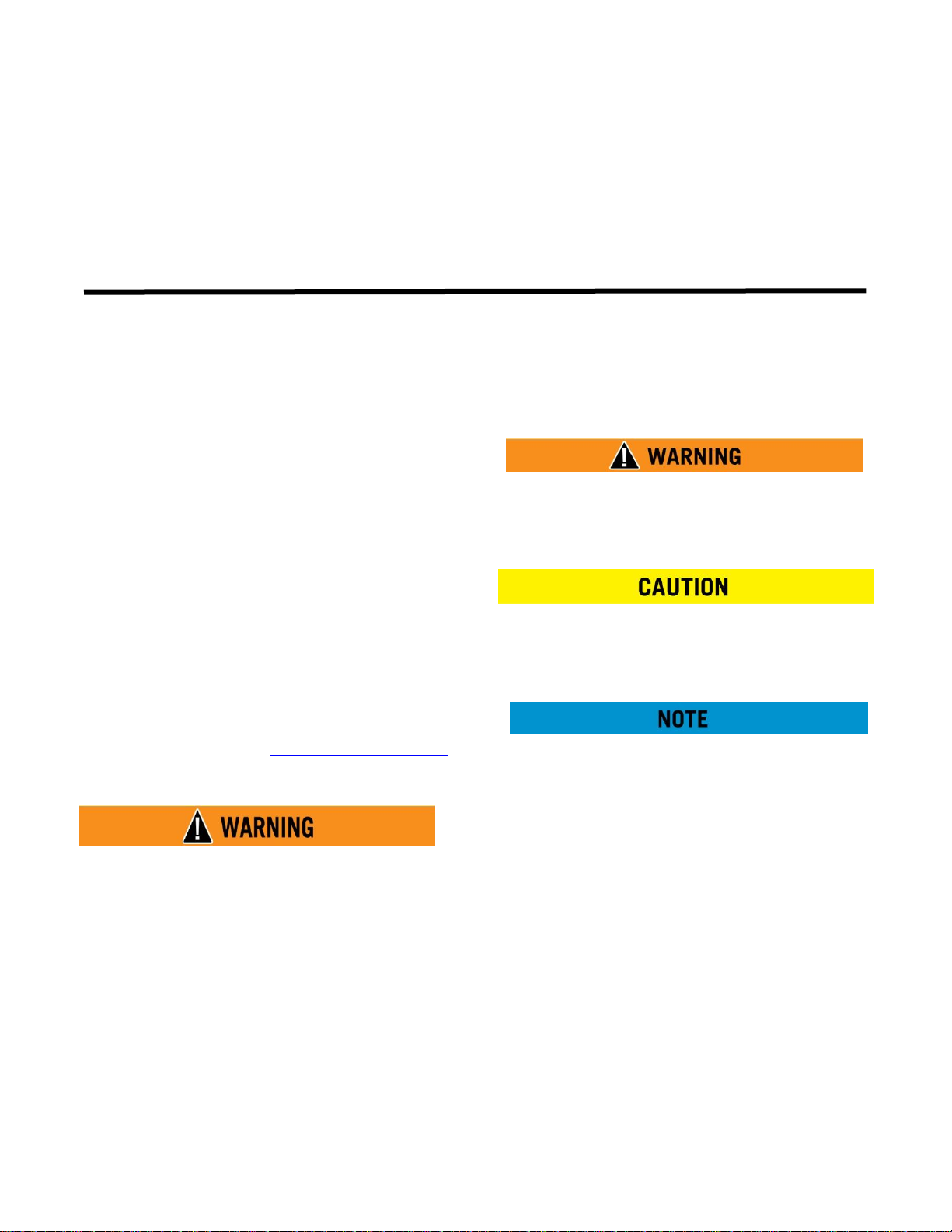
Toxic Gas Hazard (1)
This safety label is located on the side of the tank
and at all water fill entrances.
Cutting or welding operation on the inside of
the tank can cause the accumulation of toxic
gases. Read and understand instructions and
warnings in the Maintenance Manual.
Failure to provide proper ventilation or
breathing apparatus while conducting these
operations may result in serious injury or
death.
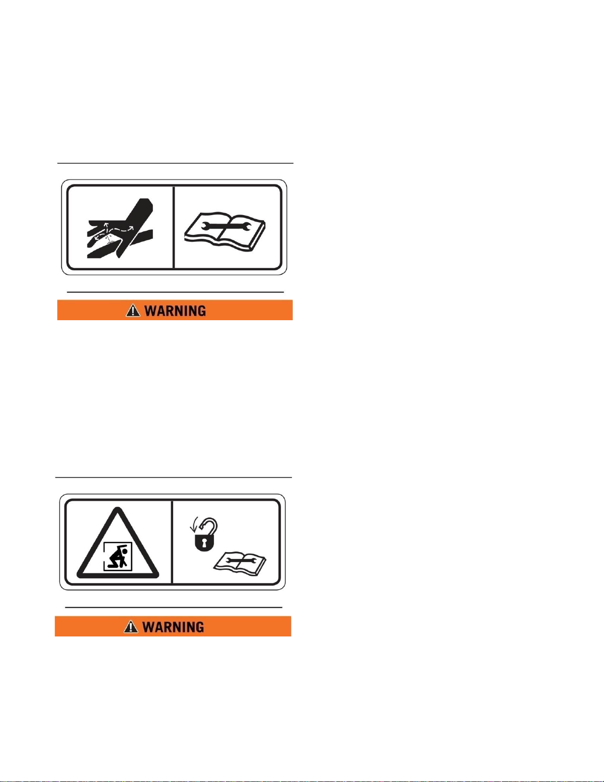
Do Not Operate (2)
This safety label is located on the outside of the
front and rear control boxes. (If equipped)
Do not open this control box unless you read
and understand the instructions and warnings
in the Operator and Maintenance Manual.
Failure to follow instructions or heed the
warnings could result in serious injury or
death.
1-2

SECTION 1
Definitions and Abbreviations
Backing Runover Hazard (3)
This safety label is located on the rear of the tank
and inside the cab.
The vehicle is equipped with a back-up alarm.
Alarm must sound when operating this
vehicle in reverse. Failure to maintain a clear
view in the direction of travel could result in
serious injury or death.
Freezing (4)
This safety label is located on the side of the
tank, at the sump drain, and on the pump.
Drain tank, fill pipe and valve in freezing
weather. Refer to the Operator and
Maintenance Manual for the procedure to
follow.
MMP4(T2)-OPS-1
4 Oct 2011
Non-Potable (5)
This safety label is located on the side of the tank
and sump drain.
Water held within tank is not potable. Do not
use tank for transport of water intended for
human or animal consumption or serious
injury or death may result.
Do Not Hoist While in Motion (6)
This safety label is located inside the cab.
Do not engage hoist cylinders while vehicle is
in motion. Before engaging hoist STOP the
vehicle. Do not engage hoisting cylinders
unless you read and understand the
instructions and warnings in the Operator or
Maintenance Manual. Failure to follow
instructions or heed the warnings will result
in injury or death.
1-3
MMP4(T2)-OPS-1
4 Oct 2011
SECTION 1
Definitions and Abbreviations
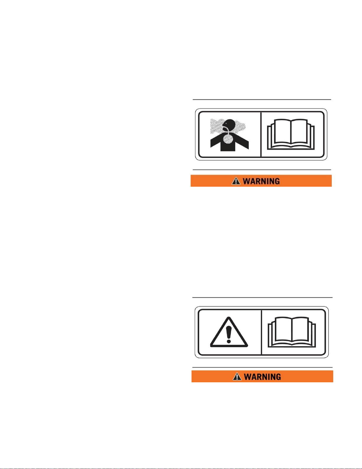
Fall Hazard (7)
This safety label is located at the top of the front
and rear of the tank.
Do not walk on the top of tank without fall
arrest PPE. Serious injury or death could
occur from a fall.
Rotating Shaft (8)
This safety label is located on the pump.
Do not place your hand or tools within pump
bell while pump is rotating and/or pressure
held within the motor supply hose. Refer to
the Operator and Maintenance Manual for
the procedures to operate and maintain the
pump. Failure to follow proper procedures
could result in serious injury.
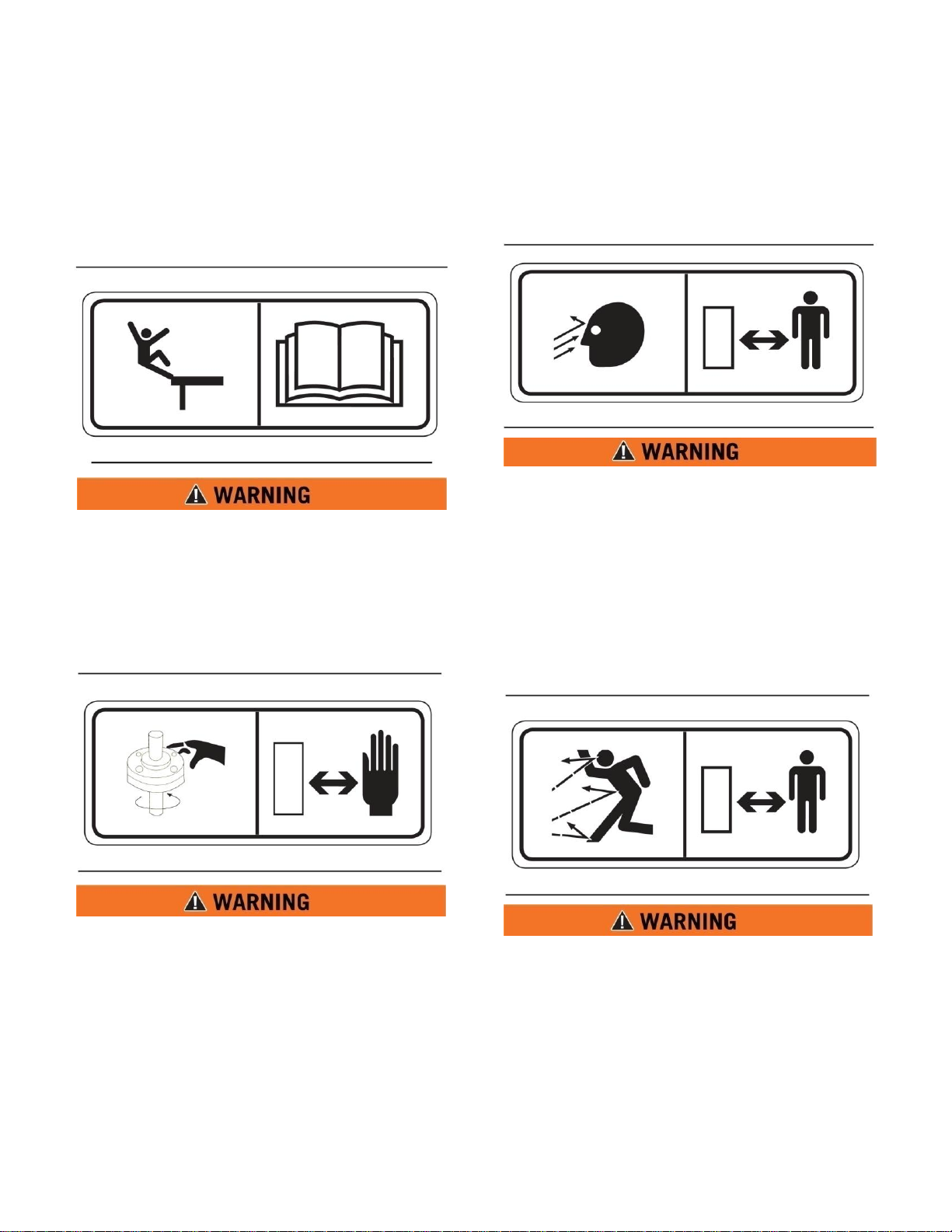
High Pressure Sprayheads (9)
This safety label is located on the spraybar.
Do not operate sprayheads until all personnel
are a safe distance away from the vehicle.
High Pressure Monitor (10)
This safety label is located on top of the cab
control box.
Do not operate the monitor until all personnel
are a safe distance away from the vehicle.
1-4
SECTION 1
Definitions and Abbreviations
High Pressure Motor (11)
This safety label is located on the hydraulic
motor.
Hydraulic motor and supply lines contain oil
under high pressure. Improper removal and
repair procedures could cause severe injury.
To remove or repair, instructions in the
Maintenance Manual must be followed.
Confined Space (12)
This safety label is located near water tank
access and fill ports.
Do not enter confined spaces without
following established site specific
procedures. Failure to follow proper safety
procedures will result in serious injury or
death.
MMP4(T2)-OPS-1
4 Oct 2011
ABBREVIATIONS
cc – Cubic Centimeters
CCW – Counter Clockwise
CW - Clockwise
fl. oz. – Fluid Ounce
FT - Feet
FPM – Feet Per Minute
GPM – Gallons Per Minute
IN/SQ FT – Inches per Square Feet
KM-H – Kilometers Per Hour
Kg – kilograms
kPa - Kilopascals
l – liters
lpm – Liters per minute
LT – Left as viewed from the operators
position facing forward
m - meters
MPH – Miles Per Hour
MMP – MEGA Mobile Pump
Nm – Newton meters of torque
psi - pounds per square inch
RPM – Revolutions Per Minute
RT – Right as viewed from the operators
position facing forward
SQ FT – Square Feet
VDC – Volts, Direct Current
1-5
MMP4(T2)-OPS-1
1
2
3
13
16 5 15 8 7
14 6 9
10
11
4 3 8 5 16
15
6 7 10
11 1413
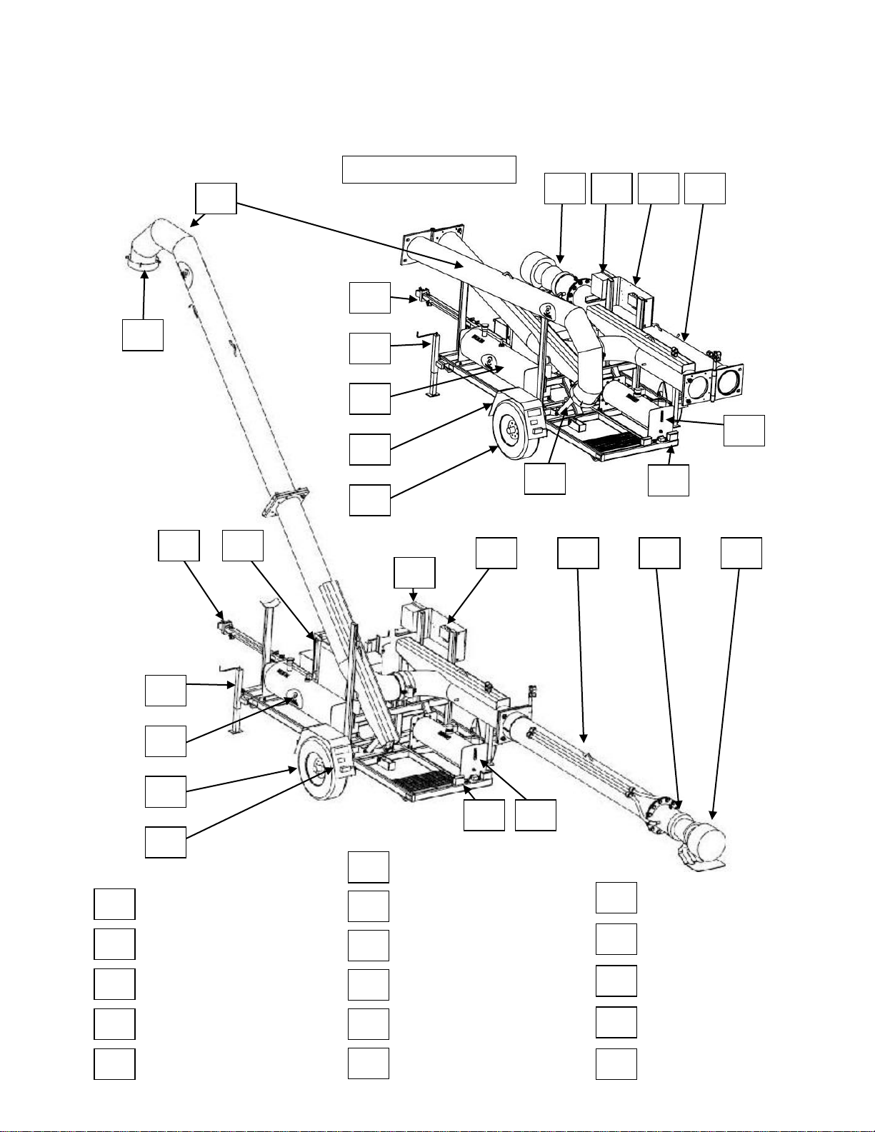
12 1 2 3 4
5
Discharge Boom
Vacuum Break
Tow Hitch
CAT 3054 Diesel Engine
Landing Gear (3)
6 7 8
9
10
11
Tire and Rim Assembly
Fender
5o Gallon Diesel Fuel Tank
Discharge Boom Lift Cylinder
Tail Lights
Hydraulic Oil Tank
12
13
14
16
15
Inlet Debris Screen
Axial Water Pump
Inlet Boom
Hydraulic Control Valve
Engine Control Box
MMP4 T2 Overview
4 Oct 2011
SECTION 1
Definitions and Abbreviations
1-6

SECTION 2
System Description
Contents
MMP4 Description and Usage ………… 2-1
MMP4 Frame …………………………… 2-1
Hydraulics ……………………………….. 2-1
MMP4 DESCRIPTION AND USAGE
The MMP4 is designed to be towed behind a
typical ¾ ton or 1 ton capacity pickup truck.
The MMP4 can be transported over the road to
just about any water holding pond area used for
filling water distribution equipment.
The MMP4 can be set up, made ready for
operation and reconfigured for transport by 1
person and simple hand tools. The MMP4’s
primary usage is to lift water from a water
holding pond and discharge the water into the
fill port on water haulage equipment. The
MMP4 is equipped with a Diesel engine with
an integrated hydraulic pump and oil cooler, 50
gallon (190 liter) diesel fuel tank, 32 gallon (87
liter) hydraulic oil reservoir, 3 circuit hydraulic
control valve, DOT rated lighting, 6,000 pound
(2,725 kg) capacity axle and tire combination, 3
point stabilizing jacking system, hydraulically
operated inlet and discharge boos, 12” axial
hydraulic drive water pump and a folding hitch
assembly. The MMP4 is capable of lifting
water approximately 25’ (7.62 meters) with a
discharge port approximately 17’ (5.2 meters)
above ground level.
MMP4(T2)-OPS-1
4 Oct 2011
Axial Water Pump ………………………. 2-2
Engine Control Box ……………………... 2-2
MMP4 FRAME
The MMP4 frame is the back bone of the unit,
manufactured using rectangular tubing.
Attached to the frame is the 6,000 lbs (2,725
kg) capacity axle assembly, boom supporting
structures, hydraulic and fuel tanks, engine
assembly including a battery and tool storage
box, a fold away hitch assembly, rear walk
way, fenders and DOT rated lighting.
HYDRAULICS
The hydraulic system of the MMP4 consists of
an engine mounted hydraulic pump, 35 gallon
(135 liter) hydraulic oil tank equipped with an
inlet screen, return oil diffuser, external shut off
valve, oil level sight glass and a breather
equipped filler cap. The balance of the
hydraulic system is designed with a 10 micron
rated return oil filter, 3 spool hydraulic control
valve with pressure regulation capability, a
hydraulic oil cooler equipped with a bypass
valve to protect against hydraulic shock when
the oil is cold, hydraulically driven submergible
12” axial water pump, hydraulic cylinders to
lift the inlet and discharge booms.
2-1
 Loading...