

Page 1
SPECIALTY HAULAGE SOLUTIONS FOR CONSTRUCTION AND MINING
Operators Manual
MCC-OPS-1
MEGA CORP.®
700 Osuna Rd. N.E. • Albuquerque, NM 87113 • 1-800-345-8889 • 505-345-2661 • Fax 505-345-6190
www.megacorpinc.com
® MEGA Corp., Inc. All Rights Reserved
Page 2

MCC35-CAT735-1
A
5 Aug 2010
TABLE OF CONTENTS
Page
Section 1. Definitions and Abbreviations .………………………………………………………. 1-1
Section 2. System Description ………………………………………………………………...… 2-1
Section 3. Normal Operations …………………………………………………………………… 3-1
Section 4. Appendix (Operators Checklist) …………………………………………………… 4-1
Page 3

MCC35-CAT735-1
5 Aug 2010
TABLE OF CONTENTS
B(Blank)
Page 4

SECTION 1
Definitions and Abbreviations
Contents
Manual Usage …………………..………. 1-1
Warning, Caution & Notes ……….…...… 1-1
Shall, Will, May ……………………….. 1-1
MANUAL USAGE
This technical manual only contains
information required to safely operate the
MEGA Container Carrier (MCC) system when
installed on the CAT 735. See the CAT 735
Operators Safety and Maintenance Manual for
chassis specific system information and
operating procedures.
Only current production systems are covered in
this manual. If your system is not covered in
this manual please contact MEGA Corp.
Product Support at: 1-800-345-8889 or visit our
web site at www.megacorpinc.com for more
detailed information.
MCC35-CAT735-1
5 Aug 2010
MCC35 Overview …………………..… 1-2
Abbreviations ………………………...... 1-3
WARNING, CAUTIONS AND
NOTES
The following definitions are found throughout
the manual and apply as follows:
Operating procedures and techniques, which
could result in personal injury and/or loss of
life if not carefully followed.
Operating procedures and techniques, which
could result in damage to equipment if not
carefully followed.
Operating procedures and techniques that are
considered essential to emphasis.
USE OF SHALL, WILL AND MAY
Shall and Will – Used when application of a
procedure is mandatory.
Should – Used when application of a
procedure is recommended.
May - Used to indicate an acceptable or
suggested means of accomplishment.
1-1
Page 5
MCC35-CAT735-1
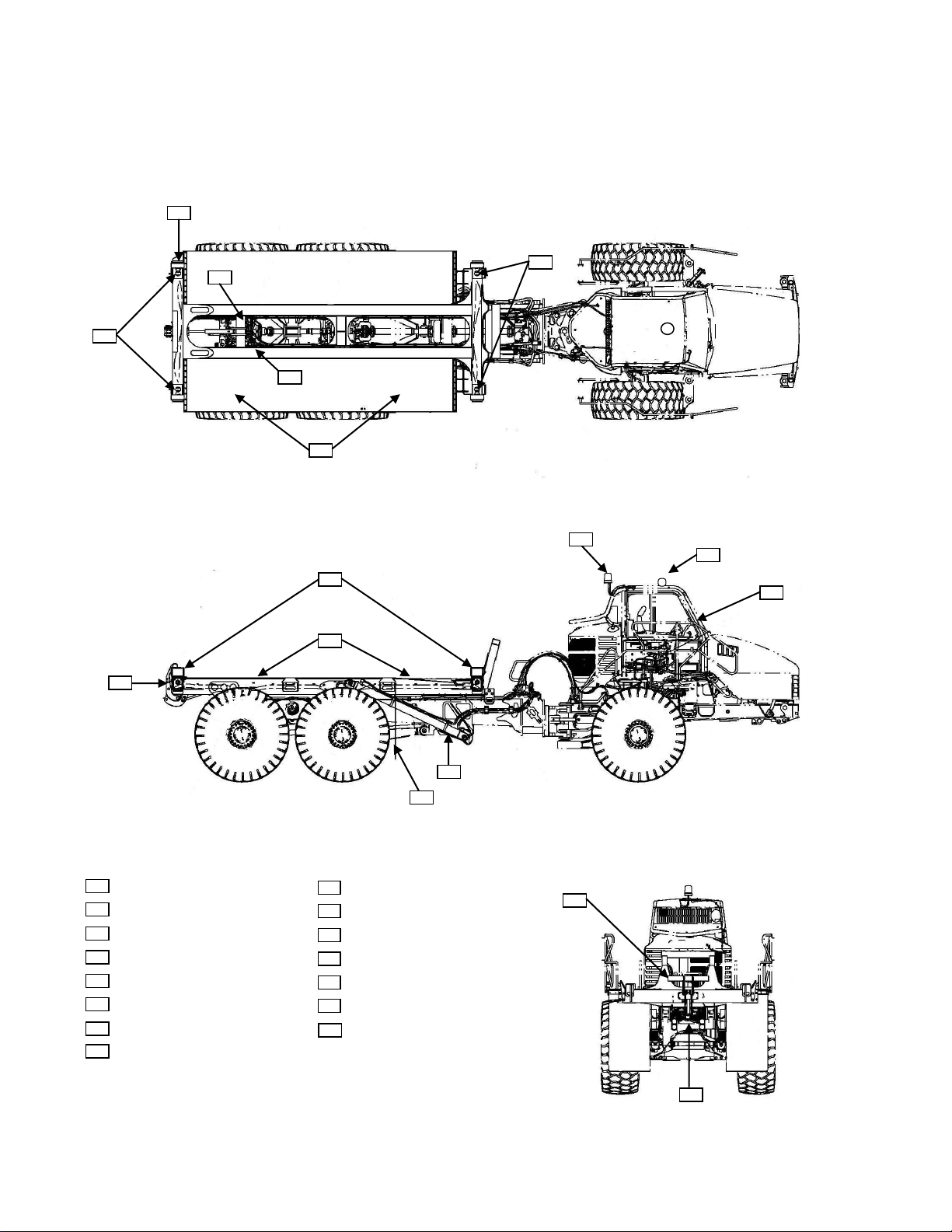
MCC35 Overview
1 2 6
3 3 8 9 4
14 7 5
12
13
11
10
15 9 10
11
12
13
14
15
Twistlock Solenoid Manifold
In-Cab Twistlock Controls
Remote Body Operation Switches
Twistlock External Status Light
Amber Flashing Beacon
Tail Lights & Accessories
Clearance Lights
1 2 3 4 5
6
7
8
Bed Assembly
Centering Guides
Twistlocks
Tailgate Restraint Assembly
Lift Cylinders
Fenders
Mud Flaps
Tailgate Operation Valve Assembly
5 Aug 2010
SECTION 1
Definitions and Abbreviations
1-2
Page 6

Definitions and Abbreviations
ABBREVIATIONS
CW – Clockwise
ECM – Electronic Control Module
ft - feet
fpm – feet per minute
IN/SQ FT – Inches per Square Feet
ISO – International Organization of
Standardization
KM-H – Kilometers Hour
Kg – kilograms
LT – Left
LWB – Long Wheel Base
M – meters
MCC – Mega Container Carrier
MPH – Miles Per Hour
OEM – Original Equipment Manufacture
PPE – Personal Protective Equipment
psi - pounds square inch
RT – Right
VDC – Volts Direct Current
MCC35-CAT735-1
5 Aug 2010
SECTION 1
1-3
Page 7

MCC35-CAT735-1
5 Aug 2010
SECTION 1
Definitions and Abbreviations
1-4(Blank)
Page 8
SECTION 2
Fender
Mud
Flap
System Description
Contents
MCC35 Description and Usage …...…....... 2-1
Body Assembly ………………………….. 2-1
Hydraulics ……………………………….. 2-2
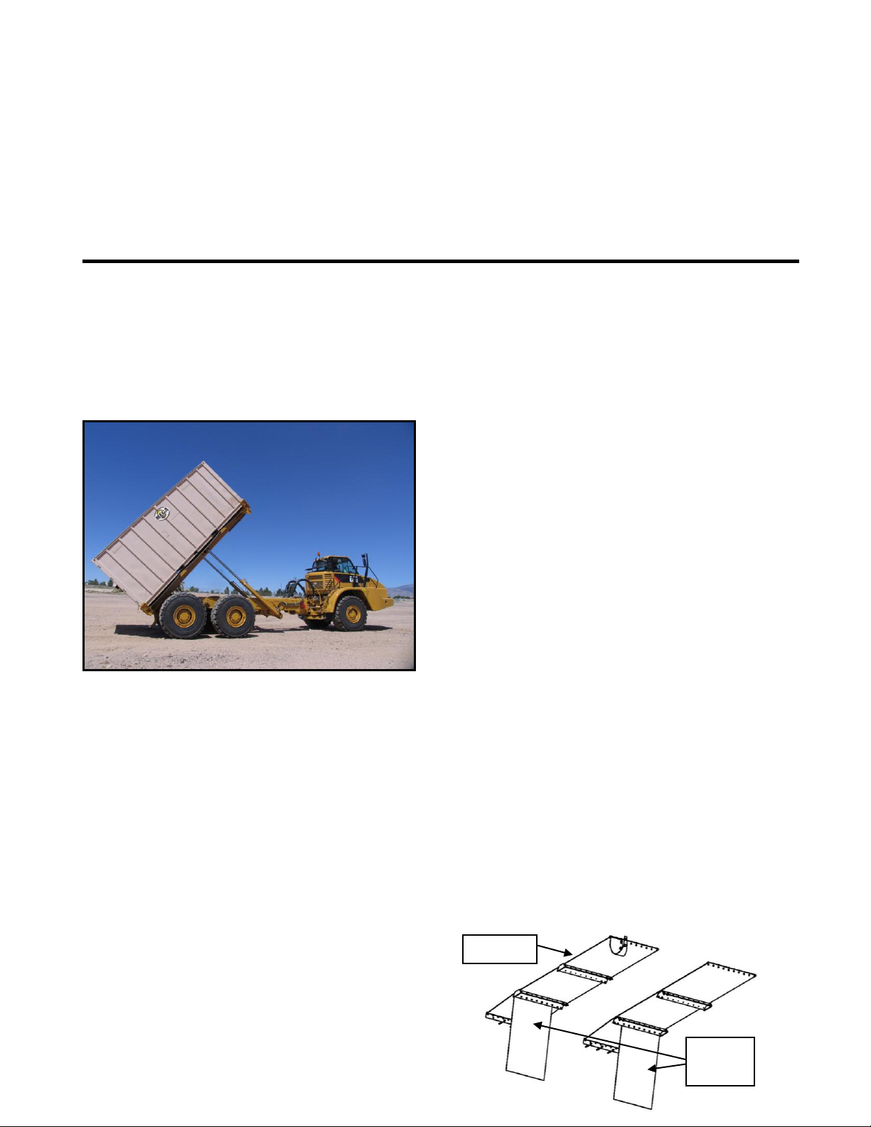
MCC35 DESCRIPTION AND USAGE
The MCC35 is designed to be attached to a long
wheel base (LWB) chassis after required chassis
reinforcements are completed. Once total
integration is completed, the assembly can be
used to mount, retain, transport, and dump a 20’
ISO container.
The MCC35 consists of a body assembly,
hydraulics and electrical systems as well as a
control system. The MCC35 is fully intergraded
with the chassis hydraulics, electrics and control
systems while adding additional in-cab controls,
lighting, and indicating/warning systems.
MCC35-CAT735-1
5 Aug 2010
Controls & Indicating System …………… 2-5
Theory of Operation ………………….….. 2-9
Lights & Accessories …………………..... 2-10
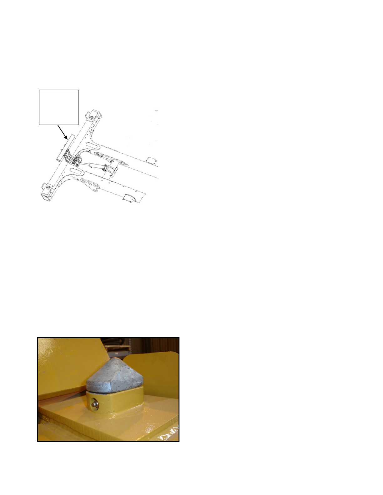
BODY ASSEMBLY
The assembly consists of a tubular frame,
fenders and mud flaps, tailgate assembly and
twistlock assemblies. The body also contains
mounting plates for hydraulic components,
sensors and accessories.
Tubular Frame
Constructed of tubular steel, cross tubes and
plating to form a frame used to carry the weight
of a loaded ISO container. The frame is secured
to the chassis by pins installed in the chassis
pivot bores and lift cylinders. The frame
incorporates container guides on each corner of
the frame to center the container over the frame
and the twistlock mechanisms. The frame also
provides for mounting of the tailgate restraint
assembly (stinger), twistlock assemblies, body
lift cylinders, body pads, body guides, fenders
and mud flap assemblies.
Fenders & Mud Flaps
The assembly is designed to protect the
container and body assembly from mud and
debris created by the drive tires. The fenders
and mud flaps assemblies are constructed of
rubber belting material and attached to
triangular metal stanchions. The stanchions are
mounted to the body assembly’s main
longitudinal beams and contain fender
tensioning devices to keep the belting just below
a loaded container.
2-1
Page 9
MCC35-CAT735-1
Tailgate
Restraint
Assembly
(Stinger)
5 Aug 2010
System Description
Tailgate Restraint Assembly (Stinger)
A steel tube and plate assembly that mounts and
pivots on the rear of the tubular frame. The
tailgate restraint assembly (stinger) is designed
to raise and restrain container doors in a closed
position when the body assembly is down. A
hydraulic cylinder is mounted between the
tailgate and tubular frame to raise and lower the
assembly as commanded by the hoist control
lever when the vehicle is in motion. The
assembly can also be operated from the tailgate
remote body operation switches when the
vehicle is stationary.
Twistlocks Assemblies
SECTION 2
The body assembly contains 4 twistlock
mechanisms located at each corners of the body
assembly. Each twistlock mechanism consists
of the 90° rotating block, hydraulic actuator
cylinder and a position sensor. The twistlocks
are designed to slide into the ISO container floor
receptacles as the container is lowered onto the
body assembly. Once the container is resting on
body assembly the twistlocks can then be
commanded to rotate 90° by using the in-cab
twistlock switch. The twisting action will allow
the lock to engage the container and secure the
container to the body assembly.
HYDRAULICS
The MCC35 hydraulic system uses chassis hoist
pressure for body and tailgate operation while
twistlock operation is accomplished by using
hoist pilot pressure. The MCC35 hydraulic
components consist of body lift cylinders,
tailgate control valve assembly, tailgate cylinder
counterbalance valve, tailgate cylinder, chassis
mounted accumulator, twistlock solenoid
manifold, twistlock actuators and associated
hosing.
Body Lift Cylinders
The body lift cylinders are MCC specific and
are mounted to the bed and chassis like a dump
body. Cylinders hydraulic pressure and return is
routed through the chassis hoist valve as
controlled by the in-cab hoist lever. The
supplemental ECM controls the body lifting
angle and places a mid-point stop at an
application specific angle. The mid-point stop
is set to keep the tailgate from contacting the
ejected load or ground and damaging the
tailgate door. A hoist mid-point override switch
is used to reactivate the hoist valve for raising
the body to the full load ejecting position.
2-2
Page 10
SECTION 2
Main Solenoid
Control Valve
Counter Balance Valve
System Description
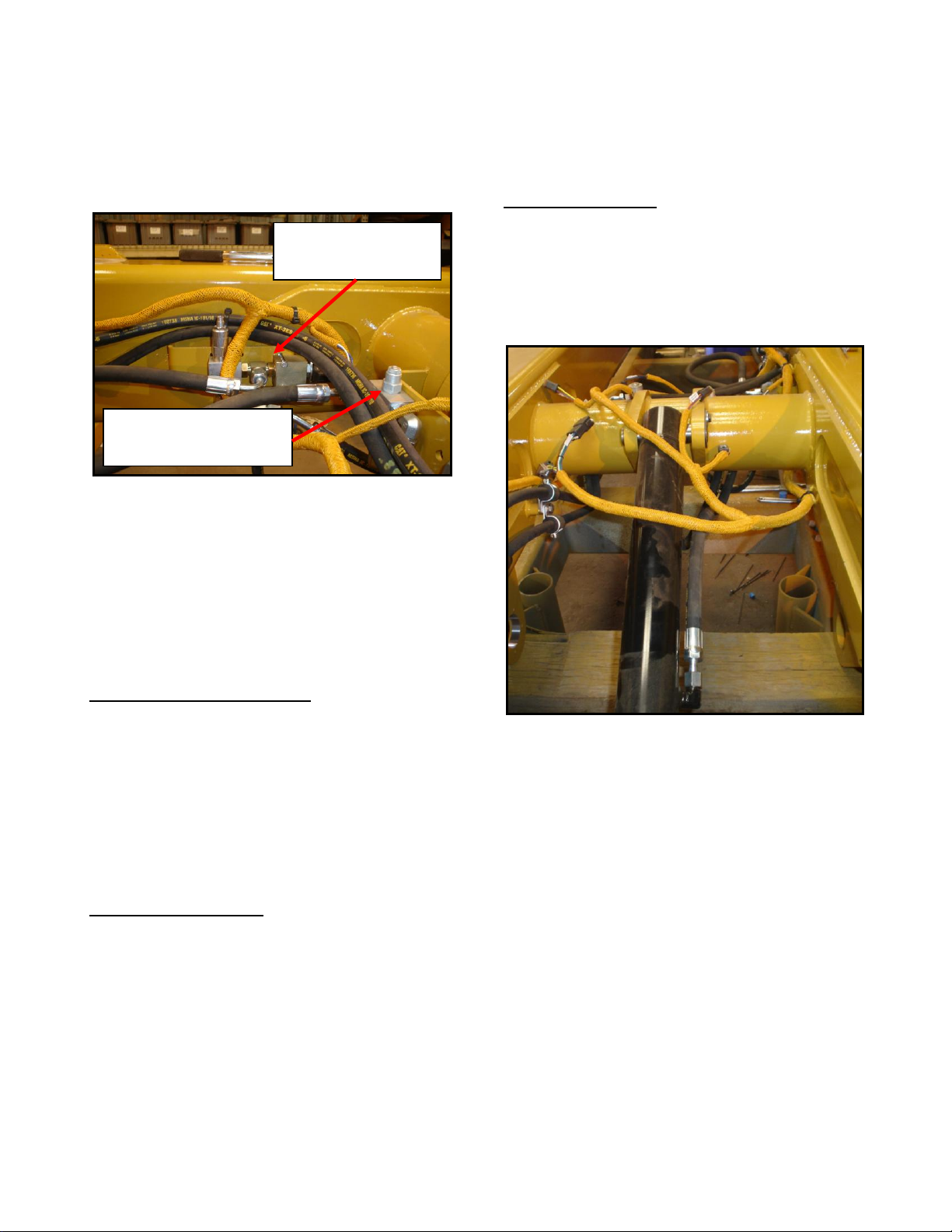
Tailgate Restraint (Stinger) Valve Assembly
The valve assembly consists of a main solenoid
control valve and a counter balance valve.
These manifolds hosed together and mounted to
the body RT main beam and cross tube
respectively. The two valve assemblies
combine to route and control hoist valve
pressure and return for the tailgate cylinder
function.
Main Solenoid Control Valve
The main solenoid control valve contains a
pressure relief and solenoid valve. The pressure
relief valve controls the clamping pressure for
the stinger to keep the tailgate door closed.
Pressure relief settings are field adjustable for
each specific type of container or load being
transported.
Counter Balance Valve
Mounted to a plate and hosed to the main
solenoid control solenoid. The valve assists in
maintaining the holding pressure for the stinger.
Pressure relief settings are field adjustable for
each specific type of container or load being
transported.
MCC35-CAT735-1
5 Aug 2010
Theory of Operation
The tailgate restraint valve assembly functions
as commanded by the remote activation
switches while the vehicle is stationary or the
hoist lever while the vehicle is in motion.
Tailgate Restraint (Stinger) Cylinder
The cylinder is connected to the body assembly
cross tube at one end and the tailgate assembly
at the other end. The cylinder receives
hydraulic pressure from the tailgate restraint
valve assembly.
2-3
Page 11
MCC35-CAT735-1
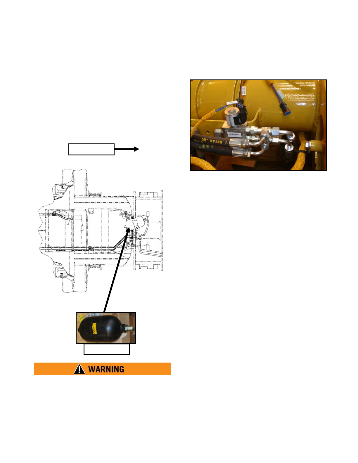
Accumulator
FORWARD
5 Aug 2010
System Description
Twistlock Hydraulic Accumulator
Mounted just to the rear of the chassis
articulation joint and is connected directly to the
hoist valve pilot pressure circuit. The
accumulator provides additional pressurized
hydraulic volume on demand for the body
twistlock manifold assembly for twistlock
operation.
Twistlock Solenoid Manifold
The hydraulic accumulator is a high pressure
charged vessel. Follow the CAT 735
Maintenance and Service Manuals for proper
charging procedures. Failure to charge this
vessel properly may result in serious personal
injury or death.
SECTION 2
Twistlock Solenoid Manifold
The manifold assembly is mounted to the body
assembly cross tube. The manifold receives
pressure from the accumulator assembly while
routing return pressure to the chassis hydraulic
tank. The manifold contains a solenoid valve to
route hydraulic pressure and return to and from
the twistlock actuators as commanded by the
twistlock controls and a pressure reducing valve
to prevent over pressurization of the twistlock
actuators.
2-4
Page 12
SECTION 2
Twistlock Actuator
System Description
Twistlock Actuators
Four twistlock actuators are mounted inside the
forward and rear lateral tubes of the bed
assembly. Each actuator is connected to the
center of the twistlock and receives hydraulic
pressure from the twistlock manifold assembly
as commanded by the twistlock controls. Each
actuator is equipped with an adjustable clevis to
allow for adjustment of the twistlock head
angle.
MCC35-CAT735-1
5 Aug 2010
CONTROLS AND INDICATING
SYSTEMS
The controls required to operate the body
assembly and integrate with the existing chassis
controls are located throughout the entire
vehicle and bed assembly. The MCC35 adds
several new control components and indicators
to increase safety and reliability for the entire
system.
The control components consist of an additional
body assembly, ECM (Electronic Control
Module), hoist lever mounted midpoint override
switch, remote tailgate restraint operation
switches, tailgate restraint control fault indicator
lamp, in-cab twistlock control switch, twistlock
position sensors, twistlock position status
indicator lamp and a roof mounted twistlock
status beacon.
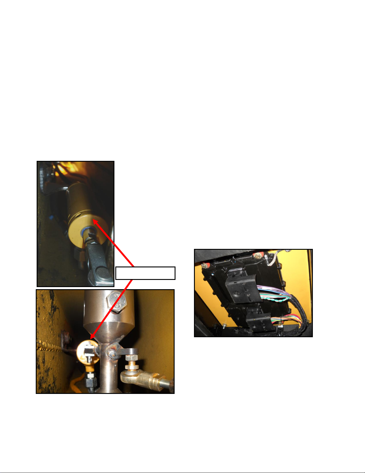
Body Assembly ECM
The unit is located under the floor of the cab
under the operator’s seat. This additional ECM
is integrated to existing chassis ECMs with
cable harnesses and loaded with a MCC35
specific software flash file.
The ECM controls and monitors hoist lever
position, hoist lever override switch, remote
body operation switch panel, bed position
sensor, in-cab twistlock switch, twistlock
position sensors, twistlock status indicating
beacon, transmission and hoist valve.
2-5
Page 13
MCC35-CAT735-1
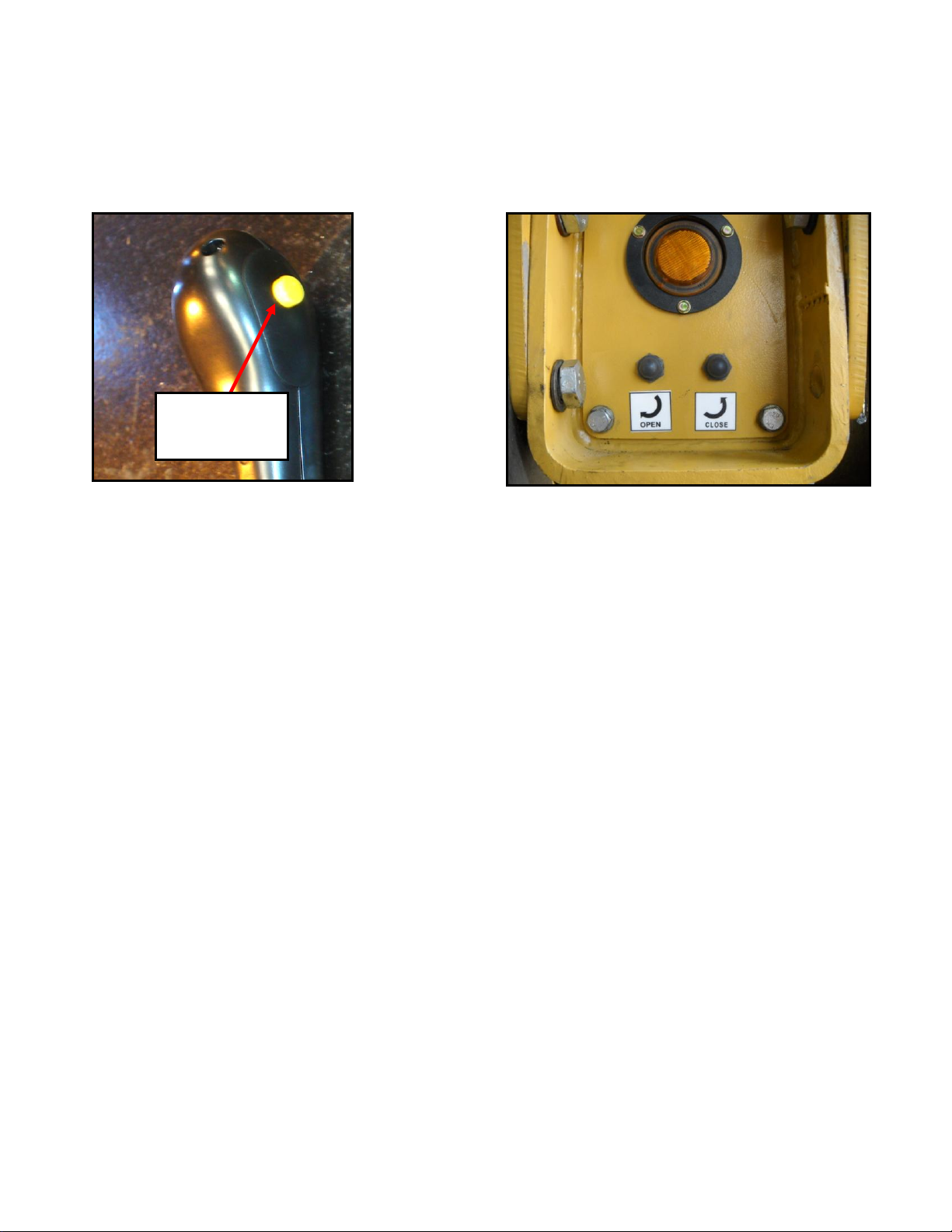
Body Midpoint
Override
Switch
5 Aug 2010
Hoist Control Lever Handle
A modified hoist lever handle replaced the
existing handle to provide a midpoint override
switch capable of disabling the ECM
commanded hoist raise stop signal. The hoist
lever still performs normal hoist functions of
RAISE, HOLD, FLOAT and LOWER as
described in the CAT Operators Safety Manual
with the exception of hoist raise automatic
midpoint stop feature as described below and in
the Body Assembly ECM. The hoist lever will
also allow tailgate functions to occur
automatically at the beginning of a raise
function (tailgate down to unrestrain container
doors) and at the end of a body lower function
(tailgate up to retain container doors) only when
the vehicle is in forward motion above 7 mph.
SECTION 2
System Description
Tailgate Remote Operation Switches
The panel is mounted on the left rear tube of the
body assembly just below the amber marker
light. The panel contains 2 switches normally
used to lower the tailgate and relieve pressure
on the container doors or to raise the stinger to
secure the tailgate for transport. These switches
will only function if the stinger fault indicator
lamp is extinguished, the hoist lever is in
FLOAT, twistlocks are in the full ENGAGED
position and the vehicle is stationary.
The OPEN switches may also be used for
limited body lift function. This function is
limited by the additional ECM as programmed.
This will prevent the body from raising above
the preset angle when the stinger OPEN switch
is depressed. If the body does RAISE the ECM
will command the hoist valve to return to the
FLOAT position and the body will lower.
2-6
Page 14

Body Position Sensor
LIGHT
STATUS
OFF
All twistlocks are DISENGAGED
FLASHING
One or several twistlocks are
transiting or a fault exists.
ON
All twistlocks are ENGAGED.
Body Position
Sensor
Twistlock
Switch
Twistlock
Indicator Light
Stinger Control Fault
Indicator Lamp
The sensor is mounted to the body assembly left
rear pivot mount. The position sensor is
connected to the chassis by an adjustable link
and provides the ECMs with angular body
positioning for automatic body raise stop
feature, in-cab body up indicator light and gear
limit functions.
In-Cab Twistlock Switch and Indicator Light
The switch and indicator light are mounted in
the existing instrument cluster. The switch
MCC35-CAT735-1
5 Aug 2010
SECTION 2
System Description
commands the twistlock solenoid manifold to
route pressure to the twistlock cylinders. The
indicator light provides the operator with an incab status of the twistlocks as follows:
In-Cab Stinger Control Fault Light
The light is mounted in the dash just to the right
of the twistlock switch. Indicates a fault exists
in the tailgate system remote switches or
circuitry.
2-7
Page 15

MCC35-CAT735-1
Blue Twistlock
Status Beacon
5 Aug 2010
Twistlock Sensors
Each twistlock sensor is mounted inside the
tubular frame and attached to its respective
twistlock by a bellcrank and adjustable clevis.
The sensor provides individual twistlock
position information to the body assembly
ECM. It is the body assembly ECM that
commands the in-cab twistlock light indications
after processing all sensor information.
External Twistlock Status Beacon
The blue twistlock status beacon assembly is
mounted to the top of the chassis cab and is
controlled by the additional ECM. The blue
beacon will only flash when all twistlocks are
DISENGAGED, indicating to the crane operator
it is safe to remove the container from the bed
assembly.
SECTION 2
System Description
THEORY OF OPERATION
The bed assembly, controls systems, indicators
and components operate as follows:
LOCKING THE CONTAINER TO THE
BODY ASSEMBLY
Once a container is lowered to the body
assembly the container must be secured to the
body for transportation and dumping. Initially
the external twistlock status beacon is ON and
in-cab twistlock status lights are OFF. The
operator then activates the in-cab twistlock
switch that in turn sends a lock signal to the
body assembly ECM. The ECM then
commands the twistlock solenoid to provide
hydraulic pilot pressure to all twistlock
actuators. Hydraulic pressure will begin to
rotate all twistlocks and twistlock sensors to a
position that will require the ECM to turn OFF
the twistlock external status light. Once all
twistlocks are in an ENGAGED position, the
ECM will illuminate the in-cab twistlock status
light. If the twistlock light does not illuminate
and a fault exists, the twistlock fault light will
illuminate.
RAISING THE BED ASSEMBLY FOR
DUMPING
The operator moves the hoist control lever from
FLOAT to RAISE. The chassis ECM will
command the hoist valve to route pressure to the
tailgate operation valve assembly. The solenoid
control valve will provide pressure to the
tailgate hydraulic cylinder and lower (OPEN)
the tailgate to unsecure the container doors.
Once the tailgate restraint (stinger) is fully
lowered, hydraulic pressure is routed to the lift
cylinders and the bed begins to RAISE. The incab body position light will illuminate and the
chassis is restricted to 1st gear.
When the bed reaches a predetermined dump
angle, as sensed by the bed position sensor, the
body assembly ECM will command the hoist
valve to stop supplying pressure to the lift
2-8
Page 16

SECTION 2
System Description
cylinders and the hoist valve will default to
HOLD. The operator will position the hoist
lever to HOLD. The midpoint stop value is set
prevent the tailgate of the container from
contacting the ejected load or the ground. This
safety feature will prevent damage to the body
assembly and the tailgate.
If the load is not fully ejected from the container
the operator may raise the bed further. This is
accomplished by positioning the hoist lever to
the HOLD position, depress and hold the
midpoint override switch and move the hoist
lever to the RAISE position then release the
override switch. The body will continue to raise
to the upper limit angle value as programmed
into the ECM software.
The midpoint stop and the upper raise limit
angles can be programmed as specified by the
type of container and the end users
requirements.
LOWERING THE BED ASSEMBY
The operator moves the hoist control lever to
LOWER position. The chassis ECM commands
the hoist valve to provide pressure to the lift
cylinders and the bed begins to lower. Once the
bed assembly is down operators should position
the hoist lever to FLOAT. Once the container
doors are closed manually, the operator should
depress the stinger CLOSE button from the
remote switches to command the stinger to raise
and restrain the tailgate. The stinger can also be
operated by the hoist control lever when the
vehicle is moving forward at 7 mph or greater
and the hoist lever is placed in the LOWER
position. This action will allow hoist valve
LOWER oil pressure through the stinger
activation control valve and CLOSE the stinger.
When the stinger is in the full CLOSE position
the operator can move the hoist lever to the
FLOAT position.
MCC35-CAT735-1
5 Aug 2010
RAISING (CLOSING) OR LOWERING
(OPENING) THE TAILGATE RESTRAINT
WITH THE REMOTE BED OPERATION
SWITCHES
The remote switches control the hoist valve
control to operate the stinger from the ground at
the rear of the machine. The hoist lever must be
in the FLOAT position, twistlocks ENGAGED,
all fault indicators OFF for this control to
operate.
LIGHTS & ACCESSORIES
The MCC35 is equipped with several different
lighting systems and accessories. They consist
of relocated chassis tail lights and accessories,
an amber flashing beacon and body assembly
clearance lights.
Tail Light & Accessory Assembly
The tail lights and other accessories are
removed from the rear of the chassis and
relocated on the MCC35 rear mounting plate.
These lights and accessories consist of tail light
modules, backup alarm and work/reverse lights.
The relocation of all lights and accessories
provides and unobstructed view of all light
systems with the MCC35 installed and loaded
with a container. The light and accessories
operate as defined in the CAT 735 Operators
Safety and Maintenance Manual.
2-9
Page 17

MCC35-CAT735-1
Amber Light-
Key ON Beacon
5 Aug 2010
System Description
Amber Flashing Beacon
Mounted to the top of the MCC35 cab and is
activated when the vehicle key switched power
is ON. This beacon serves as an anti-collision
device indication the vehicle is under power and
in service.
Clearance Lights
An amber colored light mounted on each end of
the body assembly tube cap. The lights operate
on 24 VDC and are on when the chassis running
lights or parking lights are on.
SECTION 2
2-10
Page 18

SECTION 3
Normal Operations
Contents
Description …………..…………………… 3-1
Before Operations …..………………….... 3-1
DESCRIPTION
This section provides normal bed operation
procedures for the MCC 35 on the CAT 735
LWB chassis only. These procedures are in
addition to and do not replace existing CAT
735 requirements. Refer to the CAT 735
Operations and Maintenance manual for other
specific CAT 735 operation instructions,
warnings and hazards. The MCC35 specific
operating procedures are also found in checklist
form located in the appendix and designed to
be used in the cab.
BEFORE OPERATIONS
These procedures are used to perform a walkaround inspection of the MCC35 system before
use or the beginning of a shift. This inspection
requirement is in addition to and does not
replace the vehicle manufacture’s inspections.
Ensure all safety information, warnings and
instructions are read and understood before any
operation or maintenance procedures are
performed. Ensure proper safety procedures
are used when operations the MCC35. Failure
to use proper safety procedures and equipment
may cause serious personnel injury or death.
Power OFF
1. Chocks – Set As Required
2. Vehicle Parking Brake – ON
3. Gear Selector Lever – N (Neutral)
4. In Cab Controls – Set As Required
5. Cab Mounted Indicator Beacons –
Security and Damage
MCC35-CAT735-1
5 Aug 2010
Operations ………..……………………… 3-2
After Operations ………………………… 3-4
6. MCC35 Accumulator – Security
Damage and Leaks
7. LT Body Lift Cylinder – Security,
Damage, Leaks and Lubrication
8. LT Side Body Assembly, Centering
Guides, Twistlocks, Lights, Fender and
Mud Flap – Security, Damage and
Lubrication.
9. LT Pivot Pin – Security, Damage and
Lubrication
10. Body Position Sensor – Security and
Damage
11. Remote Bed Operation Switches –
Condition, Security and Damage.
12. Tailgate Assembly – Security, Damage,
Leaks and Lubrication.
13. Twistlock Mechanisms – Security,
Damage, Operation and Lubrication.
14. Tail Light and Accessories – Security
and Damage
15. Hydraulic Sequencing and Twistlock
Manifolds – Security, Damage and
Leaks.
16. RT Pivot Pins – Security, Damage and
Lubrication
17. RT Side Body Assembly, Centering
Guides, Twistlocks, Lights, Fender and
Mud Flap – Security, Damage and
Lubrication.
3-1
Page 19

MCC35-CAT735-1
5 Aug 2010
Normal Operations
18. RT Pivot Pin – Security, Damage and
Lubrication.
19. RT Body Lift Cylinder – Security,
Damage and Leaks
20. Hydraulic Tank – Serviced as Required
Power ON Engine ON
1. Vehicle – Start
2. Twistlock Switch – DISENGAGE
3. Twistlock In-Cab Light – OFF
4. Twistlock External Beacon – ON
5. Amber Beacon – ON
6. Twistlock Switch – ENGAGE
7. Twistlock In-Cab Light – ON
8. Twistlock External Beacon - OFF
9. MCC35 Bed Raise/Lower Operations –
CHECKED FOR PROPER
OPERATION. Ensure all bed and
tailgate functions operate properly using
the hoist lever. Check bed-up position
light, raise auto stop and raise override
function properly.
10. Remote Bed Operation Switches –
CHECKED FOR PROPER
OPERATION. Ensure both remote
switches and tailgate function properly.
SECTION 3
OPERATIONS
The procedures to follow are used to safely
operate the body system for container loading,
dumping, and container unloading.
Under certain operating conditions, the
combination of hydraulic oil for the brake
system in conjunction with the hoist system
may create a slight pressure differential across
the piston heads in the hoist cylinders. If the
hoist lever is left in the FLOAT position with
this pressure differential present, the bed will
gradually return the body over the center of
balance of the pivots and the body will lower
onto the chassis. Proper use of the RAISE,
HOLD, LOWER and FLOAT positions of the
hoist control is important for the correct
operation of the machine or damage to the
machine may result.
CONTAINER LOADING
1. Body Assembly – DOWN. Ensure bed
position light is OFF.
2. Tailgate – DOWN. Use hoist lever or
remote switches to position the tailgate.
3. Hoist Lever – FLOAT
4. Twistlock Switch – DISENGAGE
5. Twistlock In-Cab Light – OFF
6. Twistlock External Beacon - ON
7. Position Vehicle – As Required for
Loading
8. Gear Selector Lever – N (Neutral)
9. Parking Brake - As Required
3-2
Page 20

Normal Operations
10. Container - LOADED
11. Hoist Lever – FLOAT
The body must be in the FLOAT position
when driving the machine. If the hoist
control lever is in any position except
FLOAT, the transmission will remain in
FIRST gear. Normal gear shifting will not
take place until the hoist control lever is
moved to the FLOAT position.
12. Twistlock Switch – ENGAGE
13. Twistlock In-Cab Light – ON
If the twistlock indicator lamp is flashing,
move the twistlock activation switch to the
DISENGAGE position and wait for the
indicator lamp to remain OFF. Then move
the switch to the ENGAGE position and
wait for the lamp to be illuminated. If after
cycling the activation switch does not
illuminate the light discontinue use of the
MCC35.
14. Twistlock External Beacon – OFF
15. Tailgate – CLOSE. Use remote
switches to position the tailgate.
Any restraining devices (e.g. chains, straps)
used on container doors for transport must
be removed after tailgate is positioned
against container door prior to dumping
operations.
16. Parking Brake – OFF
17. Gear Selector Lever – As Required
MCC35-CAT735-1
5 Aug 2010
SECTION 3
18. Move away from loading area.
CONTAINER DUMPING
1. Vehicle - Position for container
dumping.
2. Gear Selector Lever – As Required
3. Parking Brake – As Required
4. Tailgate – DOWN. Use hoist lever or
remote switches to position the tailgate.
Any restraining devices (e.g. chains, straps)
used on container doors for transport must
be removed after tailgate is positioned
against container door prior to dumping
operations.
5. Hoist Lever – RAISE. Hold in the raise
position until the bed stops
automatically.
6. Hoist Lever & Override Switch – As
Required. Use the override system as
required to dump the entire load.
7. Hoist Lever – LOWER. Ensure the bed
assembly is fully lowered and the bed
position light extinguishes.
If required, install restraining devices (e.g.
chains, straps) to keep container doors
closed for transport before the tailgate is
raised.
8. Tailgate – UP. Use remote switches to
position the tailgate.
3-3
Page 21

MCC35-CAT735-1
5 Aug 2010
9. Hoist Lever – FLOAT
The body must be in the FLOAT position
when driving the machine. If the hoist
control lever is in any position except
FLOAT, the transmission will remain in
FIRST gear. Normal gear shifting will not
take place until the hoist control lever is
moved to the FLOAT position.
10. Parking Brake – As Required
11. Gear Selector Lever – As Required
12. Vehicle – Exit dumping area
CONTAINER UNLOADING
1. Body Assembly – DOWN. Ensure bed
position light is off.
2. Tailgate – DOWN. Use hoist lever or
remote switches to position the tailgate.
3. Hoist Lever – FLOAT
4. Position Vehicle – As Required for
Unloading
5. Gear Selector Lever – N (Neutral)
6. Parking Brake - As Required
7. Twistlock Switch – DISENGAGE
8. Twistlock In-Cab Light – OFF
9. Twistlock external status beacon (Blue)
- ON
10. Container - UNLOAD
11. Twistlock Switch – As Required
SECTION 3
Normal Operations
12. Depart unloading area.
AFTER OPERTIONS
Perform this inspection at the end of the day or
end of a shift.
1. Paring Brake – ON
2. Gear Selector Lever – As Required
3. Vehicle – Shutdown
4. Hoist Lever As Required
5. Twistlock Switch – As Required
6. LT Side Bed Assembly and Components –
Security, Damage and Leaks
7. Rear Bed Assembly and Accessories –
Security, Damage and Leaks
8. RT Side Bed Assembly and Components –
Security, Damage and Leaks
9. Hydraulic Tank - Serviced
3-4
Page 22

MCC35-CAT735-1
MCC35-CAT735(CL)-1
5 Aug 2010
MCC35
OPERATORS
CHECKLIST
5 Aug 2010
SECTION 4
Appendix
4-1
Page 23

MCC35-CAT735-1
MCC35-CAT735(CL)-1
5 Aug 2010
TABLE OF CONTENTS
Title Page
1. BEFORE OPERATIONS ………… N-2
A. Power OFF …………......…… N-2
B. Power ON and Engine ON ….. N-4
2. OPERATIONS ……………………. N-5
A. Container Loading …..……… N-6
B. Container Dumping ….…..… N-9
C. Unloading Container ..……… N-11
3. AFTER OPERATIONS ………..… N-7
N-1
5 Aug 2010
SECTION 4
Appendix
4-2
Page 24

SECTION 4
MCC35-CAT735(CL)-1
5 Aug 2010
BEFORE OPERATIONS
These procedures are used to perform a walk-around
inspection of the MCC35 system before use or the
beginning of a shift. This inspection requirement is in
addition to and does not replace the vehicle manufacture’s
inspections.
Ensure all safety information, warnings and instructions
are read and understood before any operation or
maintenance procedures are performed. Ensure proper
safety procedures are used when operations the MCC35.
Failure to use proper safety procedures and equipment
may cause serious personnel injury or death.
Power OFF
1. Chocks – Set As Required
2. Vehicle Parking Brake – ON
3. Gear Selector Lever – N (Neutral)
4. In Cab Controls – Set As Required
N-2
Appendix
MCC35-CAT735(CL)-1
MCC35-CAT735-1
5 Aug 2010
4-3
Page 25

MCC35-CAT735-1
MCC35-CAT735(CL)-1
5 Aug 2010
5. Cab Mounted Indicator Beacons –Security and
Damage
6. MCC35 Accumulator – Security Damage and Leaks
7. LT Body Lift Cylinder – Security, Damage, Leaks and
Lubrication
8. LT Side Body Assembly, Centering Guides,
Twistlocks, Lights, Fender and Mud Flap – Security,
Damage and Lubrication.
9. LT Pivot Pin – Security, Damage and Lubrication
10. Body Position Sensor – Security and Damage
11. Remote Bed Operation Switches – Condition, Security
and Damage.
12. Tailgate Assembly – Security, Damage, Leaks and
Lubrication
13. Twistlock Mechanisms – Security, Damage, Function
and Lubrication
14. Tail Light and Accessories – Security and Damage
N-3
5 Aug 2010
SECTION 4
Appendix
4-4
Page 26

SECTION 4
MCC35-CAT735(CL)-1
5 Aug 2010
15. Hydraulic Sequencing and Twistlock Manifolds –
Security, Damage and Leaks.
16. RT Pivot Pins – Security, Damage and Lubrication
17. RT Side Body Assembly, Centering Guides,
Twistlocks, Lights, Fender and Mud Flap – Security,
Damage and Lubrication.
18. RT Pivot Pin – Security, Damage and Lubrication.
19. RT Body Lift Cylinder – Security, Damage and
Leaks
20. Hydraulic Tank – Serviced as Required
Power ON Engine ON
1. Vehicle – Start
2. Twistlock Switch – DISENGAGE
3. Twistlock In-Cab Light – OFF
4. Twistlock External Status Beacon – ON
5. Amber Beacon – ON
N-4
Appendix
MCC35-CAT735-1
5 Aug 2010
4-5
Page 27

MCC35-CAT735-1
MCC35-CAT735(CL)-1
5 Aug 2010
6. Twistlock Switch – ENGAGE
7. Twistlock In-Cab Light – ON
8. Twistlock External Status Beacon - OFF
9. MCC35 Bed Raise/Lower Operations – CHECKED
FOR PROPER OPERATION. Ensure all bed and
tailgate functions operate properly using the hoist
lever. Check bed-up position light, raise auto stop
and raise override function properly.
10. Remote Bed Operation Switches – CHECKED FOR
PROPER OPERATION. Ensure both remote
switches and tailgate function properly.
OPERATIONS
The procedures to follow are used to safely
operate the body system for container loading,
dumping, and container unloading.
N-5
5 Aug 2010
SECTION 4
Appendix
4-6
Page 28

MCC35-CAT735(CL)-1
5 Aug 2010
Under certain operating conditions, the combination
of hydraulic oil for the brake system in conjunction
with the hoist system may create a slight pressure
differential across the piston heads in the hoist
cylinders. If the hoist lever is left in the FLOAT
position with this pressure differential present, the bed
will gradually return the body over the center of
balance of the pivots and the body will lower onto the
chassis. Proper use of the RAISE, HOLD, LOWER
and FLOAT positions of the hoist control is
important for the correct operation of the machine or
damage to the machine may result.
CONTAINER LOADING
1. Body Assembly – DOWN. Ensure bed position light
is OFF.
2. Tailgate – DOWN. Use hoist lever or remote
switches to position the tailgate.
3. Hoist Lever – FLOAT
4. Twistlock Switch – DISENGAGE
N-6
MCC35-CAT735-1
5 Aug 2010
SECTION 4
Appendix
4-7
Page 29

MCC35-CAT735-1
MCC35-CAT735(CL)-1
5 Aug 2010
5. Twistlock In-Cab Light – OFF
6. Twistlock External Status Beacon - ON
7. Position Vehicle – As Required for Loading
8. Gear Selector Lever – N (Neutral)
9. Parking Brake - As Required
10. Container - LOADED
11. Twistlock Switch – ENGAGE
12. Twistlock In-Cab Light – ON
13. Twistlock External Status Beacon - OFF
If the twistlock indicator lamp remains illuminated or
is flashing, move the twistlock activation switch to the
DISENGAGE position and wait for the indicator lamp
to remain constant. Then move the switch to the
ENGAGE position and wait for the lamp to be
extinguished. If after cycling the activation switch
does not extinguish the light discontinue use of the
MCC35.
N-7
5 Aug 2010
SECTION 4
Appendix
4-8
Page 30

MCC35-CAT735(CL)-1
5 Aug 2010
14. Tailgate – UP. Use hoist lever or remote switches to
position the tailgate.
Any restraining devices (e.g. chains, straps) used on
container doors for transport must be removed after
tailgate is positioned against container door prior to
dumping operations.
15. Hoist Lever – FLOAT
The body must be in the FLOAT position when
driving the machine. If the hoist control lever is in any
position except FLOAT, the transmission will remain
in FIRST gear. Normal gear shifting will not take
place until the hoist control lever is moved to the
FLOAT position.
16. Parking Brake – OFF
17. Gear Selector Lever – As Required
18. Move away from loading area.
N-8
MCC35-CAT735-1
5 Aug 2010
SECTION 4
Appendix
4-9
Page 31

MCC35-CAT735-1
MCC35-CAT735(CL)-1
5 Aug 2010
CONTAINER DUMPING
1. Vehicle - Position for container dumping.
2. Gear Selector Lever – As Required
3. Parking Brake – As Required
4. Tailgate – DOWN. Use hoist lever or remote
switches to position the tailgate.
Any restraining devices (e.g. chains, straps) used on
container doors for transport must be removed after
tailgate is positioned against container door prior to
dumping operations.
5. Hoist Lever – RAISE. Hold in the raise position
until the bed stops automatically.
6. Hoist Lever & Override Switch – As Required. Use
the override system as required to dump the entire
load.
N-9
5 Aug 2010
SECTION 4
Appendix
4-10
Page 32

SECTION 4
MCC35-CAT735(CL)-1
5 Aug 2010
7. Hoist Lever – LOWER. Ensure the bed assembly is
fully lowered and the bed position light extinguishes.
If required, install restraining devices (e.g. chains,
straps) to keep container doors closed for transport
before the tailgate is raised.
8. Tailgate – UP. Use hoist lever or remote switches to
position the tailgate.
9. Hoist Lever – FLOAT
The body must be in the FLOAT position when
driving the machine. If the hoist control lever is in
any position except FLOAT, the transmission will
remain in FIRST gear. Normal gear shifting will not
take place until the hoist control lever is moved to the
FLOAT position.
10. Parking Brake – As Required
11. Gear Selector Lever – As Required
N-10
MCC35-CAT735-1
5 Aug 2010
Appendix
4-11
Page 33

MCC35-CAT735-1
MCC35-CAT735(CL)-1
5 Aug 2010
12. Vehicle – Exit dumping area
CONTAINER UNLOADING
1. Body Assembly – DOWN. Ensure bed position light
is off.
2. Tailgate – DOWN. Use hoist lever or remote
switches to position the tailgate.
3. Hoist Lever – FLOAT
4. Position Vehicle – As Required for Unloading
5. Gear Selector Lever – N (Neutral)
6. Parking Brake - As Required
7. Twistlock Switch – DISENGAGE
8. Twistlock In-Cab Light – OFF
9. Twistlock Status Beacon - ON
10. Container - UNLOAD
11. Twistlock Switch – As Required
12. Twistlock In-Cab Light – As Required
N-11
5 Aug 2010
SECTION 4
Appendix
4-12
Page 34

SECTION 4
MCC35-CAT735(CL)-1
5 Aug 2010
13. Depart unloading area.
AFTER OPERTIONS
Perform this inspection at the end of the day or end of a
shift.
1. Paring Brake – ON
2. Gear Selector Lever – As Required
3. Vehicle – Shutdown
4. Hoist Lever As Required
5. Twistlock Switch – As Required
6. LT Side Bed Assembly and Components – Security,
Damage and Leaks
7. Rear Bed Assembly and Accessories – Security, Damage
and Leaks
8. RT Side Bed Assembly and Components – Security,
Damage and Leaks
9. Hydraulic Tank - Serviced
N-12
Appendix
MCC35-CAT735-1
5 Aug 2010
4-13
Page 35

MCC35-CAT735-1
5 Aug 2010
SECTION 4
Appendix
4-14(Blank)
 Loading...