

Page 1

Air Compressor
Manual
For questions concerning this air compressor, please
call 8324156995
Page 2

TABLE OF CONTENTS
PAGE
1 Safety Guidelines - Definitions
Before Using the Air Compressor
2 When Installing or Moving the Compressor
Before Each Use
3 Follow Safety Precautions for Electrical Connection
Plan Ahead to Protect Your Eyes, Hands, Face & Ears
When Operating
4 Spraying Precautions
Perform These Maintenance Operations
5 Typical Compressor Installation
Glossary
6-8 Wiring
9-10 Starting the Compressor
11-13 Troubleshooting
14 Warranty Statement
Page 3
Page 1
Save these instructions
Before using the air compressor
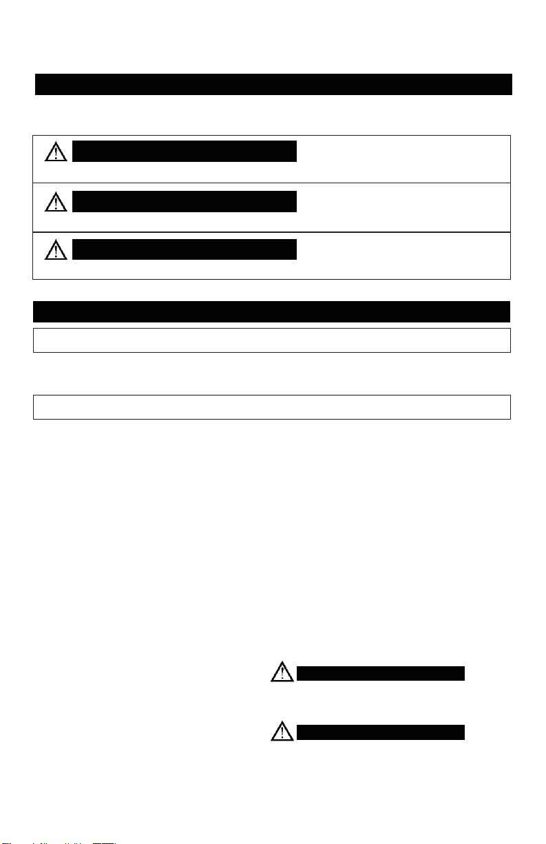
DANGER
means if safety information is not followed someone will be seriously injured or killed
WARNING
means if safety information is not followed someone could be seriously injured or killed
CAUTION
means if safety information is not followed someone may be seriously injured or killed
WARNING
DANGER
SAFETY GUIDELINES - DEFINITIONS
Safety is a combination of common sense, staying alert and knowing how your compressor works.
Read this manual to understand this compressor.
IMPORTANT SAFETY INSTRUCTIONS
Improper operation or maintenance of this product could result in serious injury and property
damage. Read and understand all warnings and operation instructions before using this compressor.
Things you should know Inspect your work area
Air compressors are utilized in a variety of air
system applications. Because air compressors
and other components (hoses, connectors, air
tools, spray guns, etc.) make up a high pressure
pumping system, the following safety precautions should be observed at all times.
Only persons familiar with these rules of
safe operation should use the air
compressor.
1.
Keep work area clean.
2.
Cluttered areas and benches invite accidents.
Floors must not be slippery from wax or dust.
Inspect your compressor
1. To reduce the risk of injury from accidental
starting, turn switch off and disconnect the
power before checking it.
1.
Read the instruction manual carefully before
attempting to assemble, disassemble or
operate your system. Be thoroughly familiar
with the controls and the proper use of the
equipment.
2.
Review and understand all safety instructions
and operating procedures in this manual.
3.
Review the maintenance methods for this
compressor (See “Maintaining Your
Compressor” section).
2. If any part is missing, bent or broken in any
way, or any electrical part does not work properly, keep the compressor off and disconnected.
3. Check hoses for weak or worn condition
before each use, making certain all connections
are secure. Do Not use if defect is found.
Do not operate compressor if damaged during
shipping, handling or use. Damage may result
in bursting and cause injury or property damage.
This compressor is Not designed for and should
not be used in breathing air applications.
Page 4
Page 2
WARNING
CAUTION
When installing or moving the compressor
WARNING
WARNING
NOTICE
NOTICE
Before each use
Flat
Washer
Floor
Vibration Pad
Compressor
(If Necessary)
Chart 1a
Lag Bolt
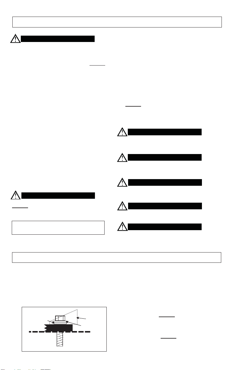
This compressor is extremely top heavy. The
compressor must be bolted to the floor with
vibration pads before operating to prevent
equipment damage, injury or death. Do Not
tighten bolts completely as this may
cause stress to the tank welds. Chart 1a.
To reduce the risk of a dangerous
environment
1.
Keep work area well lit.
2.
Operate compressor in a well-ventilated
area free from flammable liquids and vapors.
3.
Operate compressor in a ventilated area so
that compressor may be properly cooled and
the surrounding air temperature will not be
more than 100°F.
4.
Never use a compressor in a wet
environment.
5.
Protect material lines and air lines from
damage or puncture. Keep hose and
wires away from sharp objects, chemical
spills, oil, solvents and wet floors.
Do Not secure compressor with toggle bolts
into drywall. Drywall sheeting or plaster will not
support the weight of the compressor.
Always Shut Off Gas Valve before
moving Gas Drive Compressors
6.
A minimum clearance of 18 inches between
the compressor and a wall is required
because objects could obstruct airflow.
7.
The compressor should be located where it can
be directly wired to a circuit breaker. The
compressor should be wired by a qualified
electrician.
8.
Never store flammable liquids or gases in
the vicinity of an operating compressor.
9.
Do Not locate the compressor air inlet near
steam, paint spray, sandblasting areas or
any other source of contamination. The
debris could damage the motor and pump.
Never use plastic (PVC) pipe for compressed
air. Serious injury or death could result.
Never use the shipping skid for mounting the
compressor.
Electric Compressors are not suitable for
outdoor installation.
Gasoline Compressors must be operated
outdoors, sheltered from the weather.
WARNING
Never install a shut off valve between the
compressor pump and tank. Personal injury
and/or equipment damage could occur.
Inspect your work area Inspect your compressor
1.
Keep work area clean. Cluttered areas and
benches invite accidents.
2.
The floor must not be slippery from wax or
dust.
Leg
Shim
1. To reduce the risk of injury from accidental
starting, turn the switch off and disconnect
power.
2. If any part is missing, bent or broken in any
way, or any electrical part does not work
properly, keep the compressor off and disconnect power. Do Not use if defect is found.
3. Check hoses for weak or worn condition
before each use, making certain all connections are secure. Do Not use if a defect is
found.
Page 5
Page 3
CAUTION
Follow the safety precautions for electrical connections
Plan ahead to protect your eyes, hands, face and ears
WARNING
WARNING
WARNING
CAUTION
WARNING
When operating
WARNING
1.
Follow all local electrical and safety codes,
as well as the National Electric Code (NEC)
and the Occupational Safety and Health
Act (OSHA).
2.
Wiring and fuses should follow electrical
codes, current capacity and be properly
grounded.
Dress for safety
1.
Wear safety glasses (meeting ANSI Z87.1 or
in Canada CSA Z94.3-99) and use hearing
protection when operating the unit. Everyday
glasses are not safety glasses.
2.
Wear shoes to prevent shock hazards.
3.
Tie back long hair.
Pay attention to your hands
Keep fingers away from running compressor.
Fast moving and hot parts may cause injury
and/or burns.
3.
Protect wires from contact with sharp objects.
All electrical connections should be made by
a qualified electrician.
Be careful when touching the exterior of compressor, pump, motor and air lines; they may
become hot enough to cause injury.
Never operate the compressor without a
beltguard. The compressor can start automatically without warning. Personal injury or
property damage could occur from contact
with moving parts.
The compressor may be hot even if the unit is
stopped.
Use of a mask or respirator per chemical
manufacturers’ instructions may be neces-
sary if there is a chance of inhaling toxic fumes.
Read mask and respirator instructions carefully. Consult a safety expert if you are not
sure about the use of certain masks or
respirators.
1.
2.
3.
Do not exceed the pressure rating of any
component of the system.
Release pressure within the system slowly
to prevent flying dust and debris.
If the equipment starts to abnormally vibrate,
STOP the compressor immediately and
check for the cause.
Never change the safety valve or pressure
switch settings. Keep safety valve free from
paint and other accumulations. See compressor
specification decal for maximum operating
pressure. Do not operate with the pressure
switch set higher than the maximum operating
pressure.
Page 6
Page 4
Spraying precautions
WARNING
WARNING
WARNING
Perform these maintenance operations
WARNING
WARNING
Never point a spray gun at yourself or any
other person or animal. Accidental discharge
may result in serious injury.
Reduce the risk of dangerous
environment
Extreme caution should be taken when
spraying flammable liquids as the spark from
a motor or pressure switch may cause a fire
or explosion. Ample ventilation must be
provided.
Spray in a well ventilated area to keep fumes
from collecting and causing serious injury and
fire hazards.
1. Do Not spray in the vicinity of open flames
or other places where a spark can cause
ignition. Do Not smoke when spraying
paint, insecticides, or other flammable
substances.
Be informed about the materials you use
1.
When spraying with solvents or toxic chemicals, follow the instructions provided by the
chemical manufacturer. Consult a safety
expert if unsure about the use of masks or
respirators.
2.
If the material you intend to spray contains
trichloreoethane and methylene chloride, do
not use accessories that contain aluminum or
galvanized materials, as these chemicals can
react with galvanized components causing
corrosion and weakening equipment. Use
stainless steel accessories.
1.
Do regular maintenance; keep all nuts, bolts,
and screws tight, to be sure equipment is in
safe working condition.
2.
Inspect tank yearly for rust, pin holes or any
other imperfections that could cause it to
become unsafe.
NEVER attempt to repair or modify a tank!
Welding, drilling or any other modification will
weaken the tank resulting in damage from
rupture or explosion. Always replace worn,
cracked or damaged tanks.
3.
Clean electrical equipment with an approved
cleaning agent, such as a dry, non-flammable cleaning solvent.
Daily
Check oil level at sight glass. Oil level should
be 1/2 to slightly higher in the oil sight glass.
Drain moisture from tank.
Verify the pressure switch unloader is
working by listening for a brief hissing sound
when the compressor shuts off.
Visually check the compressor for loose parts,
excessive noise or vibration. Tighten any
necessary part.
4.
Drain tanks of moisture after each day’s use.
If unit will not be used for awhile, it is best to
leave the drain cock open until such time as it
is to be used. This will allow moisture to
completely drain out and help prevent
corrosion of inside of tank.
5.
Always disconnect from power source before
working on or near a motor, or its connected
load. If power disconnect point is out-of-
sight, secure it in the “OFF” position and tag it
to prevent unexpected application of power.
Disconnect power and depressurize system
before servicing air compressor. Slightly open
drain cock after shutting off compressor.
Monthly
(Make sure the main power is off.) Check the belts
for tension. Belts should not move up and down
when the compressor runs and when stopped,
should not have more than ½ in of play when
depressed. Be careful not to over tighten belts
during adjustment.
Remove and check air filter, replace if necessary.
Change oil every 3 months or 300 hours. A
compressor grade 30 wt non-detergent oil should
be used. 40 wt non-detergent for single stage.
Page 7
Page 5
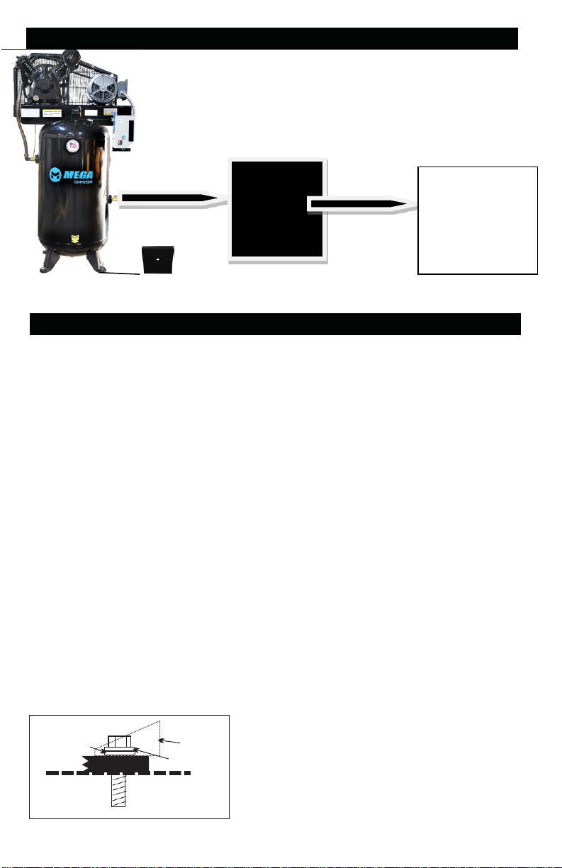
Flat
Washer
Floor
Vibration Pad
Compressor
(If Necessary)
Chart 1a
Lag Bolt
Air Regulator
Application
TYPICAL COMPRESSOR INSTALLATION
Air
Dryer
or filtration
Then into air
tools or
Air Filter
Porous element contained within a metal or
plastic housing attached to the compressor
cylinder head which removes impurity from the
intake air of the compressor.
Air Tank
Cylindrical component which contains the
compressed air.
Check Valve
Device which prevents compressed air from
flowing back from the air tank to the compressor pump.
Electric Motor
Device which provides the rotational force
necessary to operate the compressor pump.
Vibration Pads x4
GLOSSARY OF TERMS
Pressure Switch
Device which automatically controls the on/off
cycling of the compressor. It stops the
compressor when the cut-off pressure in
the tank is reached and starts the compressor
when the air pressure drops below the cut-in
pressure.
PSI (Pounds per Square Inch)
Measurement of the pressure exerted by the
force of air. The actual psi is measured by a
pressure gauge on the compressor.
Pump
Device which produces the compressed air
with a reciprocating piston contained within a
cylinder.
Safety Valve
Pressure Gauge
Device which shows the tank or regulated
pressure of the compressed air.
Leg
Shim
Device which prevents air pressure in the air
tank from rising over a predetermined limit.
Thermal Overload Switch
Device, integrated into the electric motor winding,
which automatically “shuts off” the compressor
if the temperature of the electric motor exceeds
a predetermined limit.
Page 8
Page 6
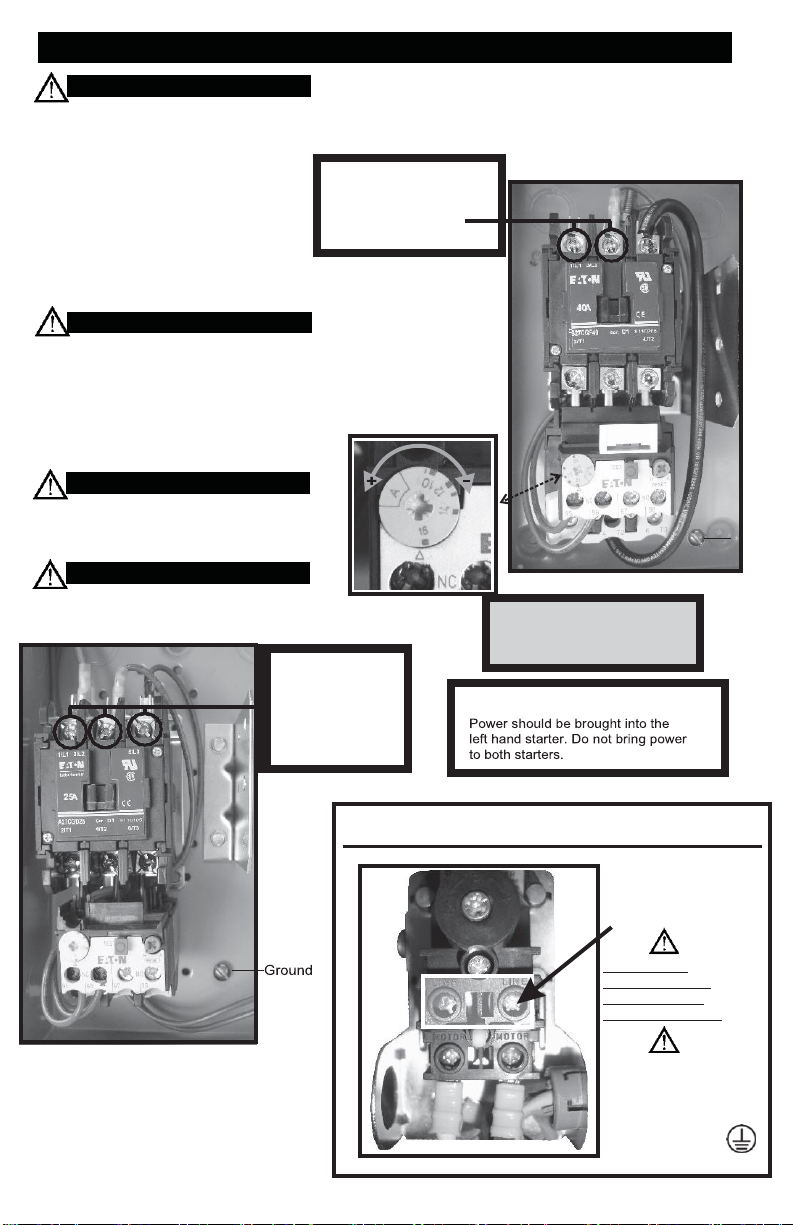
Three Phase
Incoming power
Magnetic Starter.
(Units with Magnetic Starters)
WARNING
CAUTION
DUPLEX
For Models Without Magnetic Starter
connections should be
WARNING
WARNING
WIRING
ALL ELECTRICAL WIRING SHOULD BE DONE
BY A QUALIFIED ELECTRICIAN
General Information
Adequate wiring and motor protection
should be provided for all stationary
compressors. Wiring used for other
machinery should not be used. A
qualified electrician familiar with local
electrical codes in your area should be
used. Size supply wiring per NEC (National
Electric Code) requirements.
To reduce the risk of electrical hazards, fire
hazards or damage to the compressor, use
proper circuit protection. Your compressor
is wired at the factory for operation using
the voltage shown. Connect the compressor
to a power source with the correct breaker
size.
Electrical connections must be properly
grounded. Ground connections should be
connected at the grounding screw.
Overheating, short circuiting and fire damage
will result from inadequate wiring.
Incoming power should
be connected to L1 and
L2 at the Top of the
Magnetic Starter.
Adjustment
should be
connected to
L1, L2 & L3 at
the Top of the
Overload
Single Phase
DO NOT MAKE CONNECTIONS
AT THE PRESSURE SWITCH
Ground
Incoming power
should be connected
to the posts
marked (LINE)
Do Not Make
Connections On
Prewired Posts
Marked (MOTOR)!
Electrical connections
must be properly
grounded. Ground
connected at a
grounding screw.
Page 9
Page 7
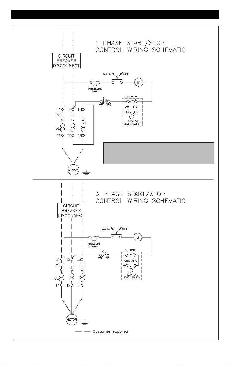
WIRING
Single and Three Phase
With Mag Starter
Page 10
Page 8
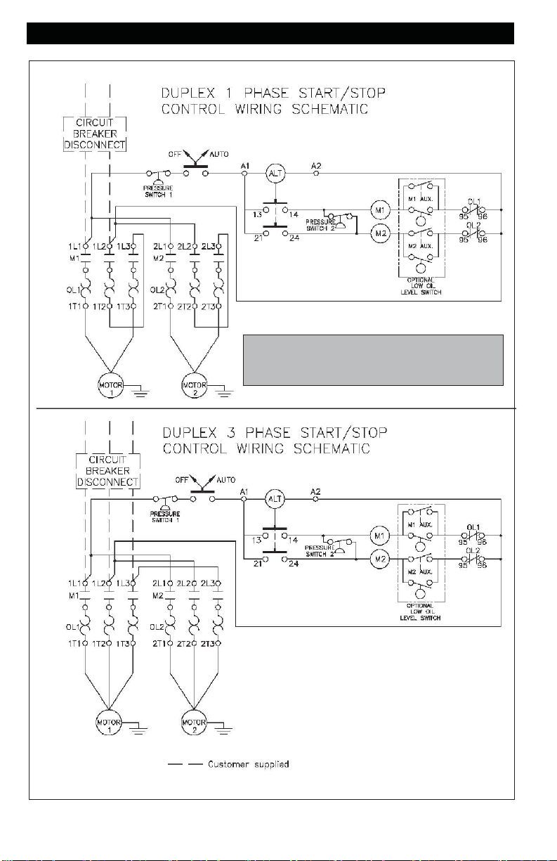
WIRING
Single and Three Phase
Duplex
Page 11
Page 9
STARTING THE COMPRESSOR
CAUTION
(Gas Drive Models)
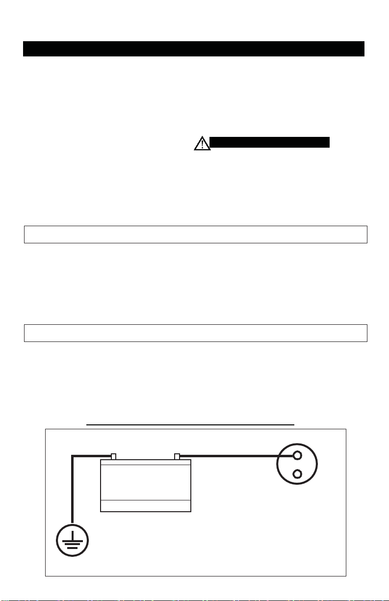
Battery Connection Instructions for Electric Start Engines
GROUND
Starter Solenoid
BATTERY
(12 Volt)
(+)
(-)
Prior to actually running the compressor,
check the following items:
Crankcase oil - Make sure the sight glass
shows ½ full or slightly above.
Make sure all rags, tools, oil, etc. are away
from the unit.
Open the air system to free it of any pressure.
Switch the compressor on for a few
revolutions to make sure the rotation is
correct. Correct rotation is clockwise
when facing the sight glass on the pump.
Operate the compressor for a few minutes
unloaded (air system open) then allow the
compressor to pump up. Make sure the
electrical pressure switch properly switches
off the compressor according to the setting
desired. 175 for Two Stage.
(135 psi - Single Stage or 165 psi - RCP-561VNS)
Make sure the pressure in the tank does
not exceed its rating. Single Stage units - 135 psi
Two Stage units at a maximum of 175 psi.
(165 for Model RCP-561VNS)
If the pressure gauge indicates a pressure that
is higher than these maximum pressures,
shut off compressor immediately and call
your distributor.
PLEASE REFER TO YOUR ENGINE OPERATION MANUAL FOR PROPER STARTING
INSTRUCTIONS.
GASOLINE DRIVEN COMPRESSORS ARE EQUIPPED WITH A COLD START
VALVE FOR LOADLESS STARTS.
NOTE: IN SOME INSTANCES, IT STILL
MAY BE NECESSARY LIFT THE TOGGLE ON THE UNLOADER/PILOT VALVE
TO RELIEVE THE HEAD PRESSURE. See Page 11
Note:Make sure to follow instructions carefully to avoid a short and possible damage
to the starter solenoid and/or battery.
1. Connect the positive (+) terminal on the battery to the starter solenoid.
2. Connect the negative (-) terminal on the battery to an engine mounting bolt or other
acceptable ground connection.
Always connect the positive(+) battery cable to the starter solenoid before connecting
the negative(-) battery cable.
NUMBER 2 WIRE OR LARGER IS REQUIRED
Page 12
Page 10
Cold Start Procedure (Gasoline Engine Units)
Warning: Do Not Operate Gasoline Engine
Units in an Enclosed Area
Release any remaining tank pressure by slowly opening the
manual drain valve.
Turn on the engine gasoline supply.
Put the choke in the “On” position
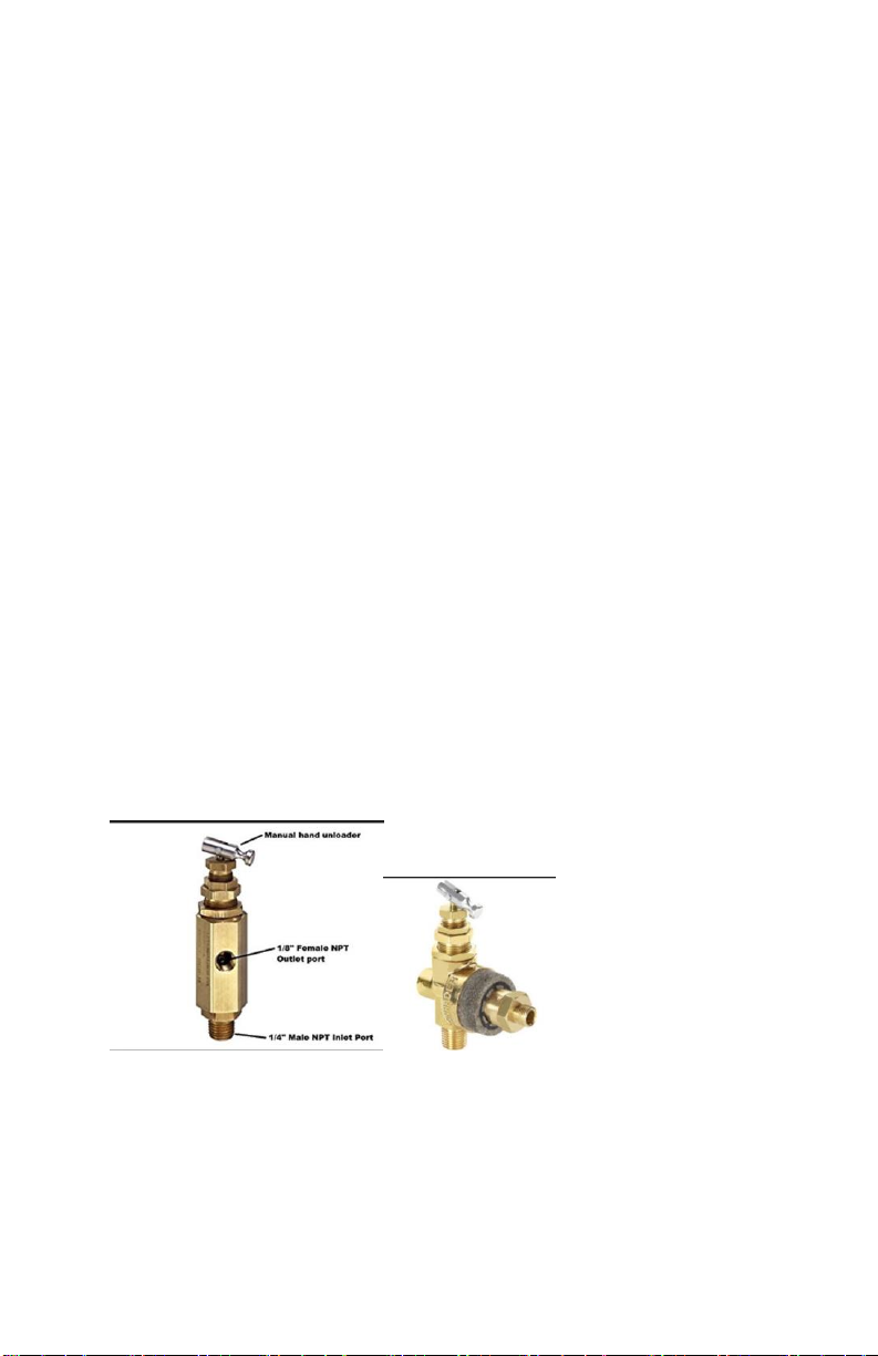
Close the service valve and put Unloader lever in the “unload”
(A)
position for Honda engine driven models.
Start the engine, release the choke, and allow the engine to
warm up for two to three minutes.
Return the unloader lever to the “load” (B) position for Honda
driven models. As shown Below for the Manual head
Unloader
Note: Turn the gasoline supply off before shutting down
the compressor.
Page 13
Page 11
TROUBLESHOOTING GUIDE
Low discharge pressure
1. Compressor too small for
application
2. Air leaks
3. Restricted intake air
4. Blown gasket(s)
5. Broken or misaligned valves
1. Reduce air demand or use a compressor
with more air capacity.
2. Listen for air leaks. Apply a soap solution
to all fittings and connections. Bubbles
will form at points of leakage. Tighten
or replace fittings or connections.
3. Clean or replace air filter.
4. Replace necessary gaskets.
5. Remove head and inspect for broken or
misaligned valves. Replace valves, if
necessary.
!
CAUTION
Install a new head gasket
each time head is removed
Excessive noise
“knocking”
1. Loose drive pulley or flywheel
2. Low on oil
3. Worn connecting rod or
connecting rod bearing
4. Noisy check valve
1. Tighten drive pulley or flywheel bolt.
2. Check for proper oil level. Low or dirty
oil may cause bearing damage.
3. Replace connecting rod and/or connecting
rod bearings.
4. Replace check valve.
!
DANGER
Do not remove check valve
with air pressure in tank
Excessive oil carryover
1. Worn piston rings
2. Restricted intake air
3. Too much oil in compressor
4. Incorrect oil viscosity
1. Replace with new piston rings.
2. Clean or replace air filter.
3. Drain oil to proper oil level.
4. Use a quality non-detergent 30 or 40wt
oil specified for each model (Page 4).
Water in tank and/or
discharge line
1. Normal. Amount of water will
increase as humidity in the
air increases.
1. Drain tank at least once per day.
2. Add an inline filter to reduce moisture in
the air line.
Will not run or motor
hums
1. Low voltage
2. Malfunctioning pressure switch
3. Malfunctioning check valve
1. Check voltage with volt meter across both
legs of incoming power. Check reset button
on motor.
2. Repair or replace pressure switch.
3. Replace check valve or pressure switch.
!
DANGER
Do not remove check valve
with air pressure in tank
Breaker or reset
repeatedly trips
1. Incorrect breaker size
2. Low voltage
3. Malfunctioning motor
4. Loose electrical connections
5. Malfunctioning pressure switch
6. Malfunctioning check valve
1. Make sure the breaker is sized properly.
See page 6 in this manual.
2. Check voltage with volt meter across both
legs of incoming power.
3. Replace motor.
4. Check all electrical connections.
5. Adjust or replace pressure switch.
6. Replace check valve.
!
DANGER
Do not remove check
valve
with air pressure in tank
Tank does not hold
pressure when not
running and shut off
valve is closed
1. Malfunctioning check valve
2. Loose fittings or connections
3. Crack or pin hole in tank
1. Replace check valve.
!
DANGER
Do not remove check valve
with air pressure in tank
2. Tighten or replace fittings or connections.
3. Replace tank. Do not attempt to repair tank.
Page 14

Page 12
TROUBLESHOOTING GUIDE (Continued)
Pressure switch unloader constantly
leaking air
1. Malfunctioning check valve
1. Replace check valve if unloader bleeds
constantly.
!
DANGER
Do not remove check valve
with air pressure in tank
Pressure switch not
unloading
1. Malfunctioning pressure
switch
1. Replace pressure switch if it does not release
air pressure briefly when unit shuts off.
Do not remove pressure
!
DANGER
switch with air pressure in
tank
Excessive vibration
1.
Improper installation
2.
Loose belts
3.
Misaligned flywheel or
drive pulley
1.
Make sure unit is mounted on a level surface
with vibration pads.
2.
Replace belts. Align and tighten properly.
3.
Align flywheel and drive pulley.
Overheating
1.
Compressor too small for
application
2.
Cooling surfaces dirty
3.
Improper cooling
1.
Reduce air demand or use a compressor
with more air capacity.
2.
Clean all cooling surfaces of dirt and dust.
3.
Install compressor in an area with adequate
cool dry air.
Page 15
Page 13
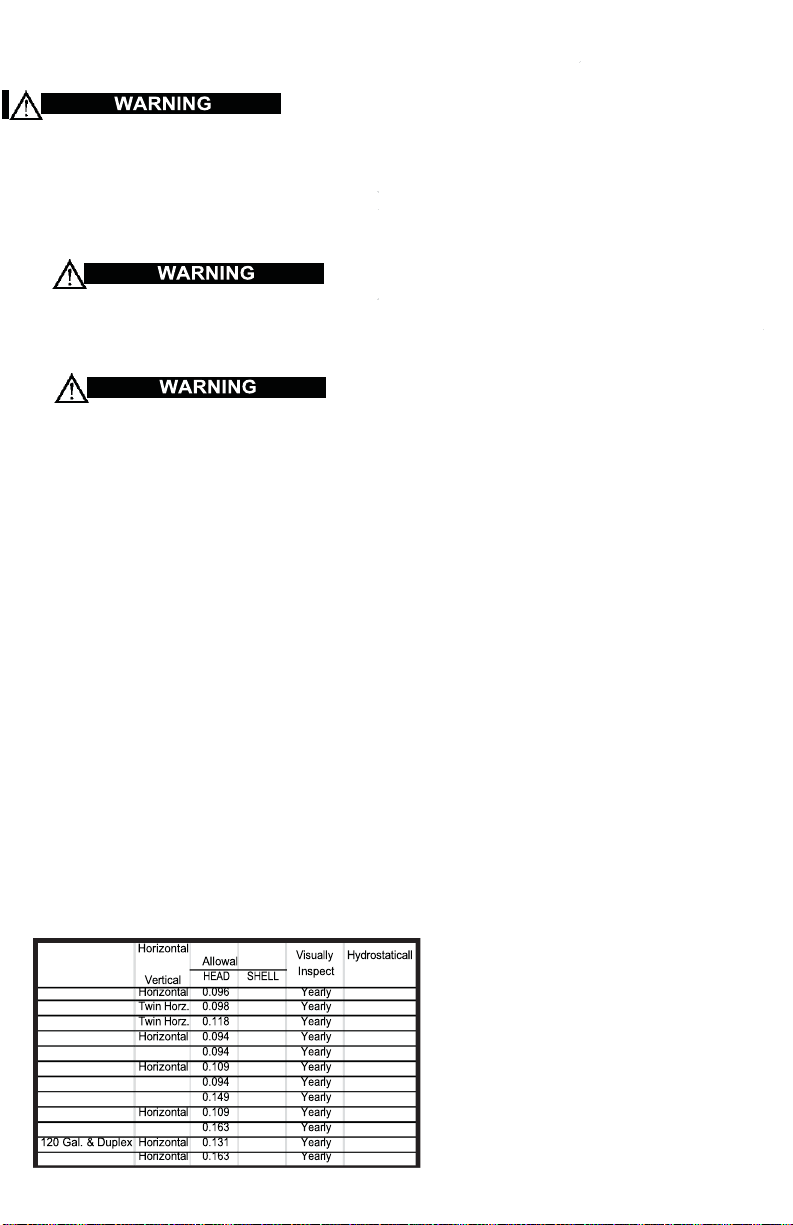
Tank Capacity
Mini
mum
le Wall
8 Gal.
0.094 10 Years
8 Gal.
0.098 10 Years
10 Gal.
0.118 10 Years
20 Gal.
0.094 10 Years
26 Gal.
Vertical
0.094 10 Years
30 Gal.
0.098 10 Years
60 Gal.
Vertical
0.094 10 Years
80 Gal.
Vertical
0.133 10 Years
80 Gal.
0.133 10 Years
120 Gal.
Vertical
0.199 10 Years
0.159 10 Years
200 Gal. Duplex
0.199 10 Years
Oil and moisture residue must be drained from the air receiver
daily or after each use. Accumulations of oil residue in the receiver
can be ignited by embers of carbon created by the heat of compression causing an explosion, damage to property and injury to personnel
Do not open a manual tank drain valve on any air tank containing
more than 30 PSIG of air pressure!
Never attempt to releive an air tank by removing a pipe plug or
any other system component!
Manually Draining An Air Tank:
Step 1)
Disconnect & lockout the compressor from the power source (elec
tric models) or disconnect the spark plug wire from the spark plug
(gas engine models).
Step 2)
Tank(s) subjected to freezing temperatures may contain ice. Store
the compressor in a heated area before attempting to drain mois
ture from the tank(s). Reduce the air pressure in the tank to 30
PSIG by pulling the pressure relief valve ring (refer to
Checking Pressure Relief Valves & Relieving System Pres
sure ).
Step 3)
Slowly open the drain valve and allow the moisture and air mixture
to drain from the tank.
Step 4)
Recommended Air Tank Inspection Intervals
Once the moisture has been completely drained, close the drain
valve.
Air Tank Inspection
or
Fig. 3-4,
y Inspect
The factory recommends that all
air tanks be inspected at scheduled inter vals. Refer to
Tank Inspection Intervals Table
relative information.
Recommended Air
for
Refer to federal, state or provincial,
or local codes for mandatory air tank
maintenance information.
Page 16

Warranty
Guarantee MegaPower Inc. warrants that all MegaCompressor®
compressors will be free of defects in material and workmanship for a period
of twelve months from the date of initial retail purchase, or eighteen months
from the date of manufacture, whichever may occur first. Should any failure
to conform to this warranty be reported to the company within said period,
the company shall, upon purchaser shipping the compressor to our plant
transportation prepaid, correct such nonconformity by suitable repair or, at
its option, furnish a replacement part F.O.B. our plant. MegaPower Inc,.
shall not be liable for any unauthorized repairs, replacements, adjustments
to the compressors, or the costs of labor performed by the purchaser. This
warranty is expressly in lieu of all other warranties expressed, implied or
statutory (including, but not limited to, warranties of merchantability and
fitness for purpose) and of any other obligations, and/or liabilities on the part
of MegaPower Inc,. MegaPower Inc neither assumes nor authorizes any
other person to assume for it any other obligations or liability in connection
with or with respect to any compressor. MegaPower Inc shall in no event be
liable neither for any consequential, incidental or special damages nor for
the improper selection of any compressor for a particular application.
MegaPower Inc is devoted to continual quality control and thorough
research of the products we build. It is our creed to give you, the user, all of
the experience and engineering available in the production of every piece of
equipment we produce. Our line covers the complete needs of today’s
varied air requirements. Rely on MegaCompressor® for all the newest and
finest features that are available for the modern compressor.
Page 17

 Loading...