

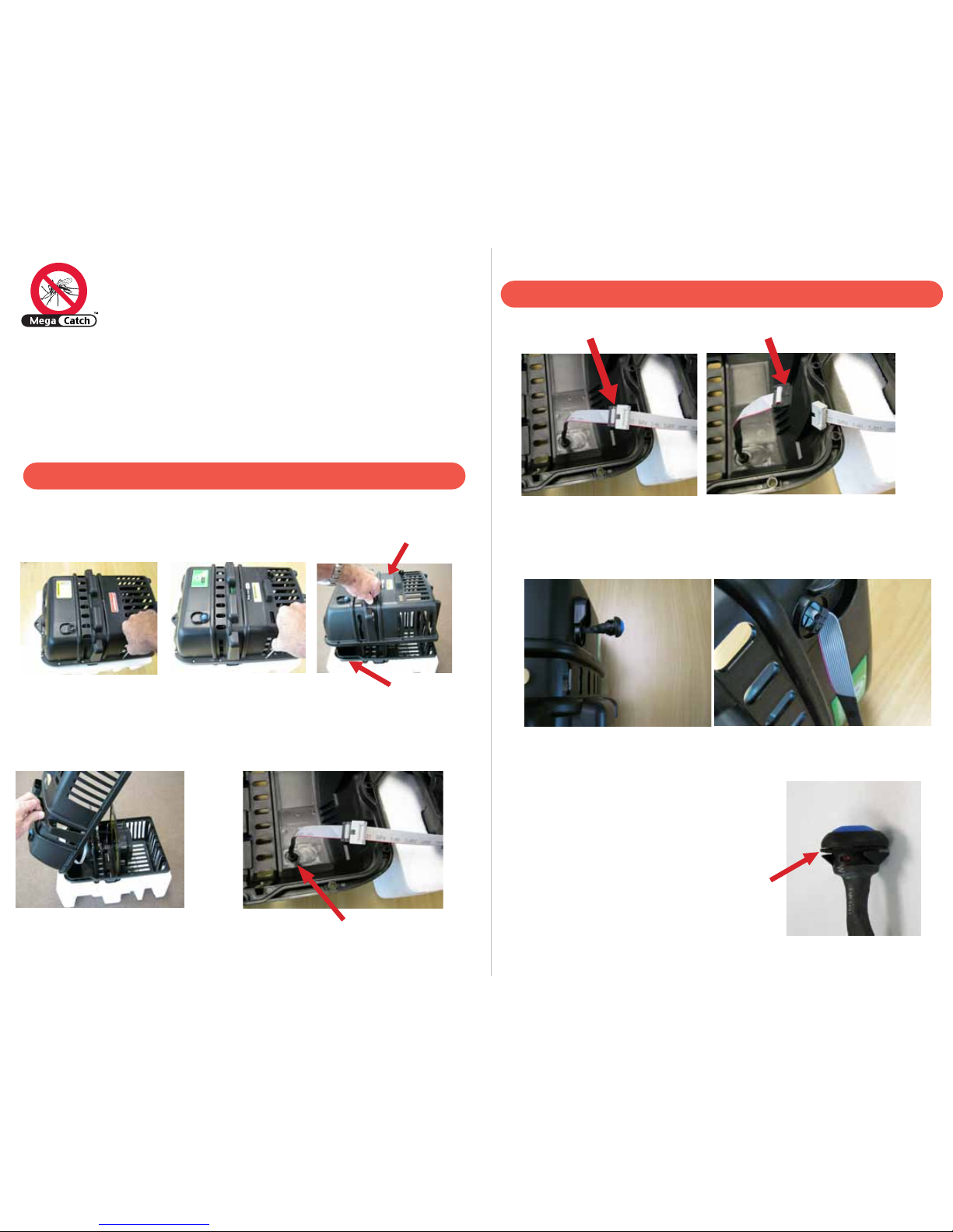
Step 1). Disconnect the black/grey ON/OFF switch ribbon connector (Fig 6 &
Fig 7)
Mega-Catch™ Mosquito Traps have a modular design that enables the user to
easily perform maintenance/repairs on the Trap without the costly charges
required to send the Trap to a service centre.
Please refer to the instructions below on how to correctly open the mosquito trap.
ENSURE POWER IS DISCONNECTED
To Open Your Mosquito Trap
Fig 1
Fig 4
Fig 3
Fig 2
Step 2). Remove the On/Off switch through the front of the unit by
exerting pressure on the switch from the inside of trap (Fig 8 & Fig 9).
Step 3). Replacement is the reverse of removal.
Take care when inserting connector and ribbon
cable through front of unit.
Ensure rubber backing washer in place (Fig 10).
Fig 7
Fig 6
Fig 9
Fig 8
Fig 10
To Replace the On/Off Switch
Fig 5
Place the Trap on a table or other suitable flat surface ensuring the ON/OFF switch
is facing downwards (Fig 1) remove 6 bolts. Turn Trap over (Fig 2) so that the
ON/OFF switch is now face up and remove 6 bolts.
Raise ‘Front Half’ of Trap (Fig 3) a couple of inches. Then ‘flip’ the ‘Front Half’ over
(Fig 4) as if it were hinged at the top. The ON/OFF switch is located in the ‘Front
Half’ of the Trap as shown (Fig 5).
‘Rear Half’
ON/OFF switch
‘Front Half’
REPLACEMENT INSTRUCTIONS
Pro 900 PREMIER
ON/OFF SWITCH
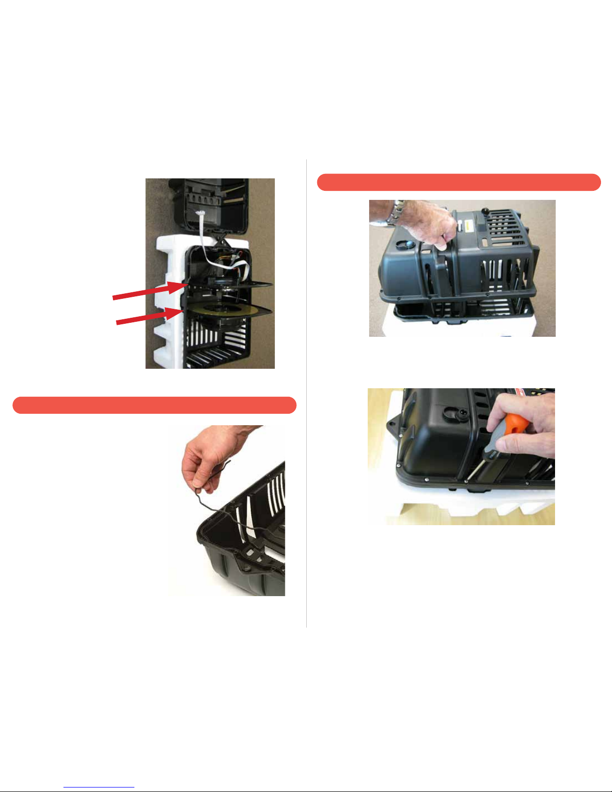
Fitted to the groove around the top inner
surface of the Trap is a rubber seal. This
seal pushes into place for weather
protection and should be reinstalled prior to
final assembly of the Trap. The seal is
formed to the shape of the Trap.
Removal / Reinstallation of Seal
Re-assembly of Trap
Step 4). Once all connections
are made, ensure all ‘Plates’ and
cables are correctly located
following the instructions as
detailed under ‘Maintenance
and Repair of Your Trap’ in the
Operation Manual.
‘Top Plate’
‘Bottom Plate’
The 12 screw holes should now be aligned for replacement of the screws and
nuts. Hold the nuts into the pre-formed hexagonal holes and carefully screw
in the screws.
Note: Do not overtighten the screws. This could cause the nuts to rotate and
damage the pre-formed hexagonal fittings in the plastic housing.
Connect power and test operation.
With the ‘Top Plate’ and ‘Bottom Plate’ in place in the ‘Rear Half’ of the Trap,
replace the ‘Front Half’ of the Trap (containing the ON/OFF switch) ensuring
that each ‘Plate’ slots into the locating ribs.
 Loading...