

Page 1
MULTITRUCK 400 – 600
Repair manual
Page 2

Contents
GROUP 1
Engine accessories
cooling fan
GROUP 3
Gearbox
Continuous variable transmission
IBC repair manual
GROUP 4
Front Axle
GROUP 5
Rear Axle
GROUP 6
Wheel
Handbrake
Brake
GROUP 7
Body shell
GROUP 8
Display features
- Tachymeter
- Fuel gauge
- Odometer
- Gearbox position
- Service
- Turning lights and hazard lights
- Indicator lights
- Pre-heating system
- Engine stop
Group 9
Paint
Page 3
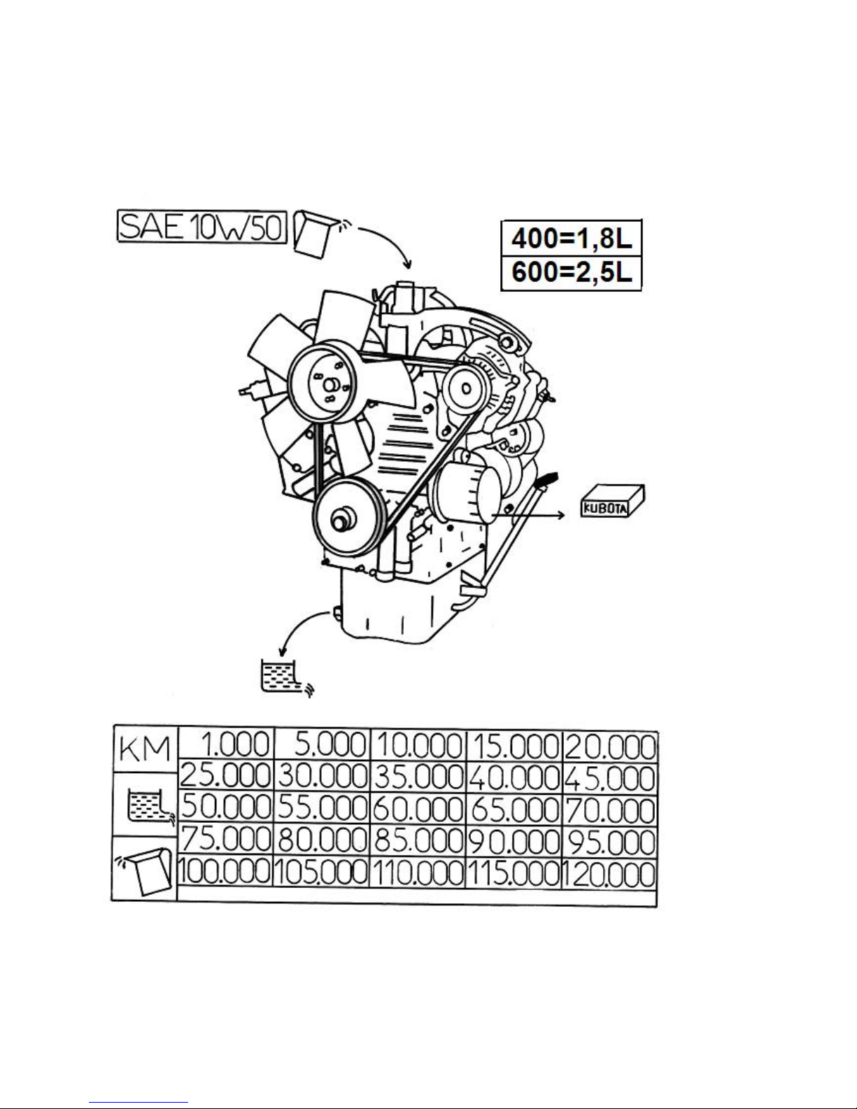
GROUP 1
Engine Oil
Page 4
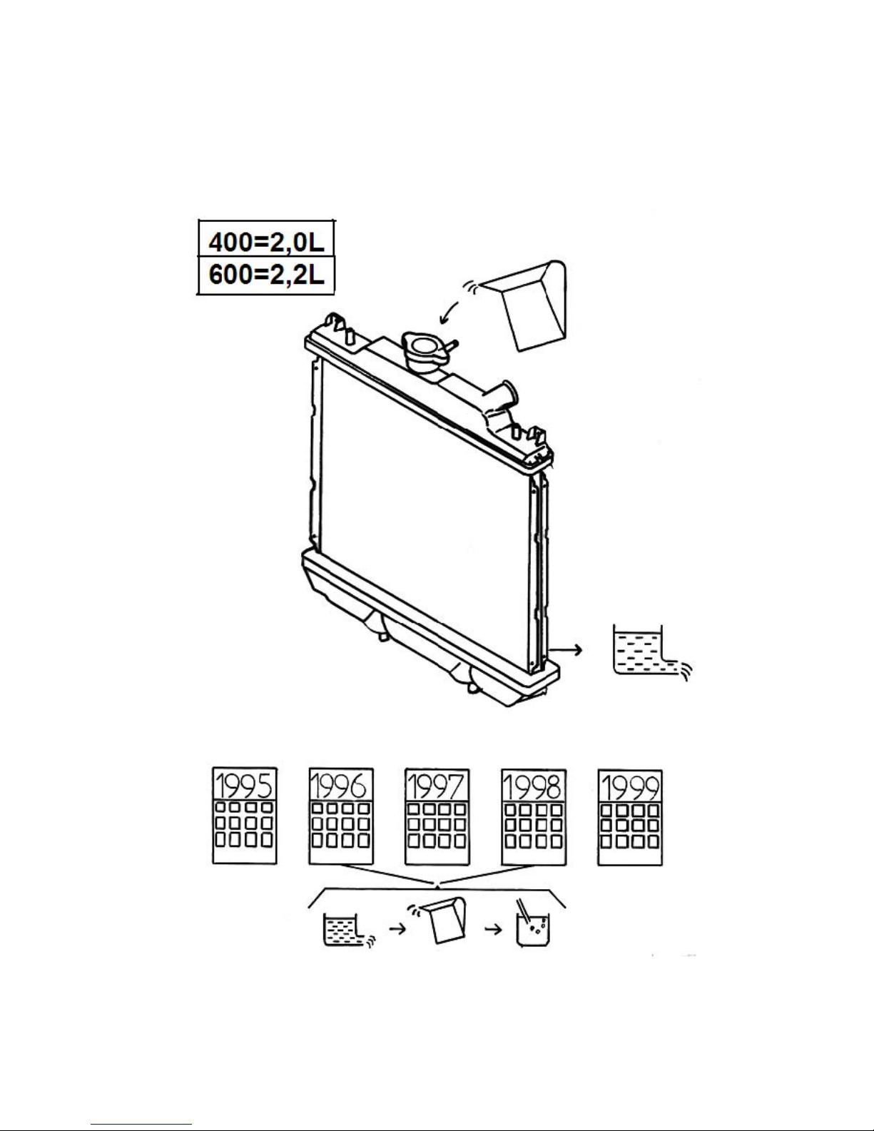
Cooling system
Page 5
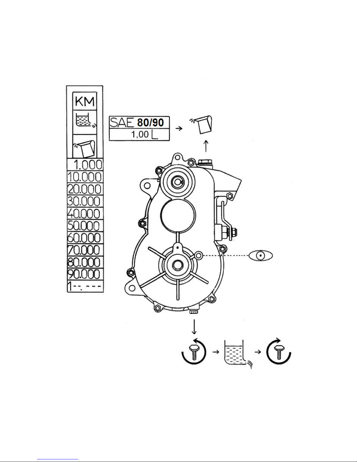
GROUP 3
Gearbox
Page 6
Continuous variable transmission
Page 7
CVT Service
Page 8
Maintenance Guide
Variable Speed Power
Transmission System
VSP 2000 / LP2
CVTech-IBC Inc.
300 Labonté Street
Drummondville, Quebec
Canada J2C 6X9
www.cvtech-ibc.com
Most recent update: 2004-01-13
Page 9

Table of Contents
Important Notice....................................................................................................3
Maintenance Frequency ........................................................................................3
Handling Tools You’ll Need.................................................................................4
Parts of the Transmission System .........................................................................5
Removing the Pulleys from the Vehicle ...............................................................6
Removing the Drive Pulley................................................................................6
Removing the Driven Pulley..............................................................................8
Inspecting the Drive Belt....................................................................................8
Disassembling and Reassembling the Pulleys ......................................................9
Disassembling the Drive Pulley.......................................................................10
Reassembling the Drive Pulley ........................................................................13
Disassembling the Driven Pulley.....................................................................15
Reassembling the Driven Pulley ......................................................................19
Reinstalling the Pulleys on the Vehicle ..............................................................21
2
Page 10

Important Notice
)
Only qualified personnel can perform maintenance and repair operations on the
variable speed transmission system.
L Means there is a risk of serious injury if the instructions are not followed as
¾
described.
¾
, Means that, when performing this step, there is a risk of damaging a part or of the
components malfunctioning.
¾ CVTech-IBC is held harmless of any and all liability as concerns damage or injury
resulting from the incorrect understanding of the text, improper use of the transmission
system, or improper use of the recommended tools.
¾ It is very important that you use the tightening torque indicated.
Maintenance Frequency
The transmission system does not require any lubrication. It is designed to work without
lubricants. Given this, you have to apply certain rules of cleanliness when handling the system
to avoid having any products come into contact with its components.
To increase the life of the transmission system, it is strongly recommended that you inspect
the following:
Description Inspection Maintenance Interval
Drive pulley
Stationary sheaf Visual at 10 000 km
Sliding sheaf Visual at 10 000 km
Assembled centrifuge
unit
Lower bearing Visual Replace at 10 000 km
Spring Visual at 10 000 km
Upper bearing Visual Replace at 10 000 km
Driven pulley
Stationary sheaf Visual at 10 000 km
Visual
General condition
Visual at 10 000 km
Visual
General condition
at 10 000 km
at 10 000 km
Sliding sheaf Visual at 10 000 km
Cam fittings Dimensional (see page 18) at 10 000 km
Spring Visual at 10 000 km
Drive belt
Visual
Dimensional (see page 8
3
at10 000 km
Page 11
Flathead screwdriver
b
p
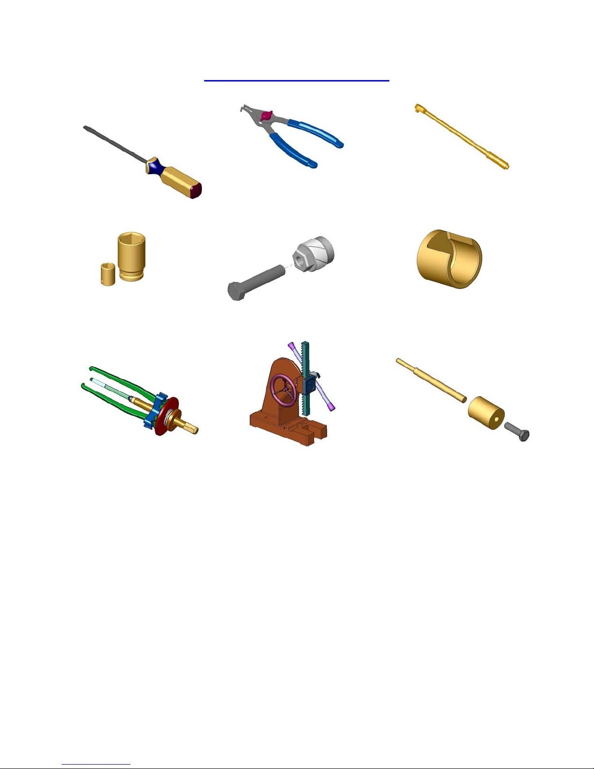
Handling Tools You’ll Need
Torque wrench
Pliers to remove
the locking ring
17mm and 30mm
ushings
Extractor
Driven pulley extractor
Pillar press or drill
ress
Dismantling tool
for the driven pulley
Drive pulley extractor,
20 mm or 0.75 inch thread
*** Important: Using impact tools is not recommended.***
4
Page 12
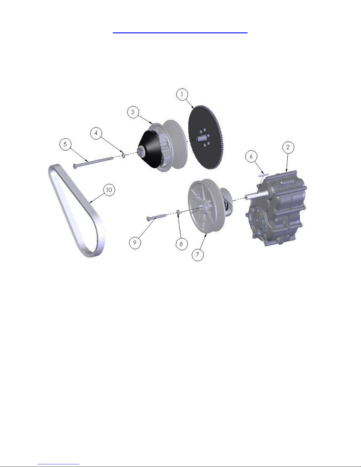
Parts of the Transmission System
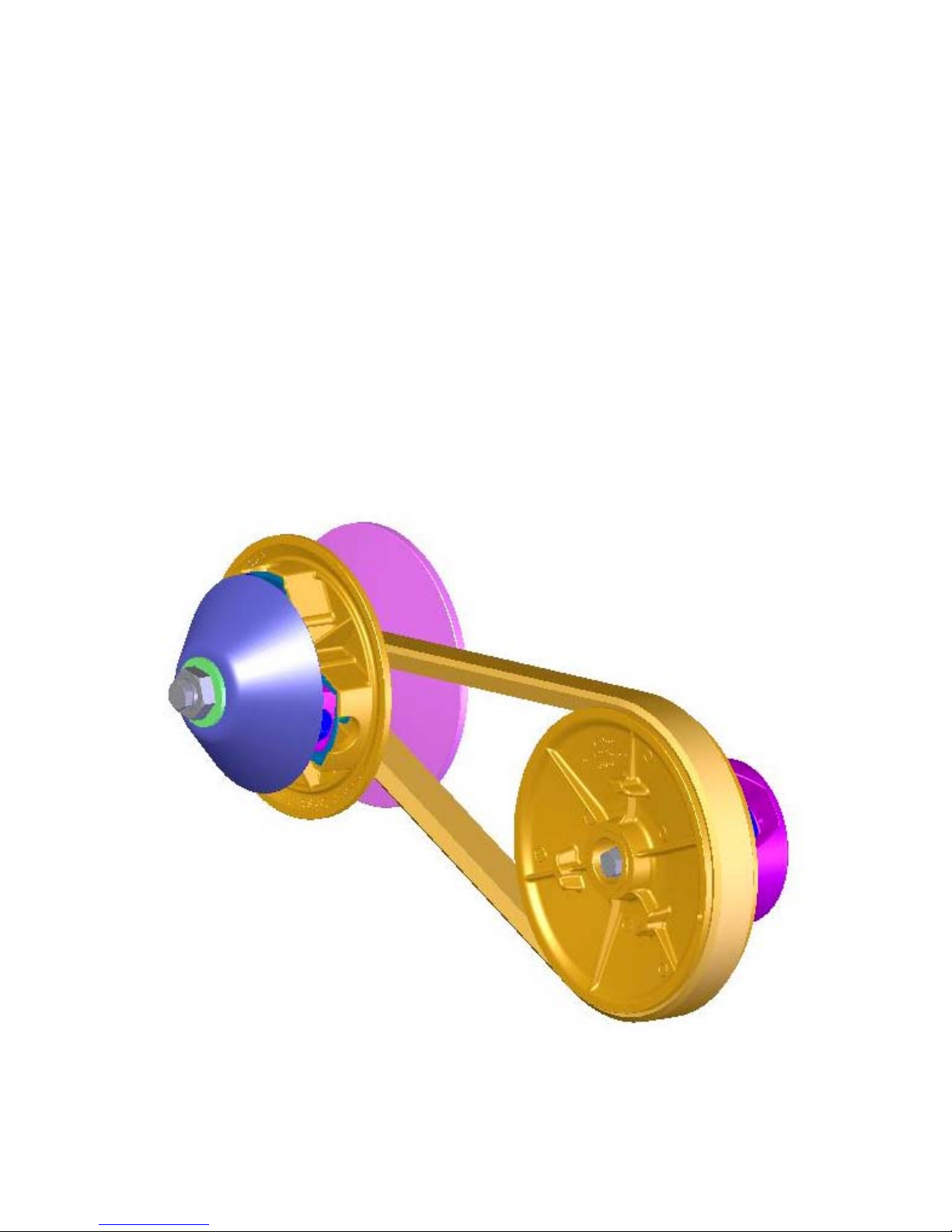
The transmission system is made up of three main parts: the Drive Pulley (3), the Driven
Pulley (7) and the Drive Belt (10).
1...Flywheel
2...Gearbox
3...Drive pulley
4...Lock washer
5...Hexagon bolt (retaining)
6...Pin
7...Driven pulley
8...Lock washer
9...Hexagon bolt (retaining)
10.Drive belt
5
Page 13
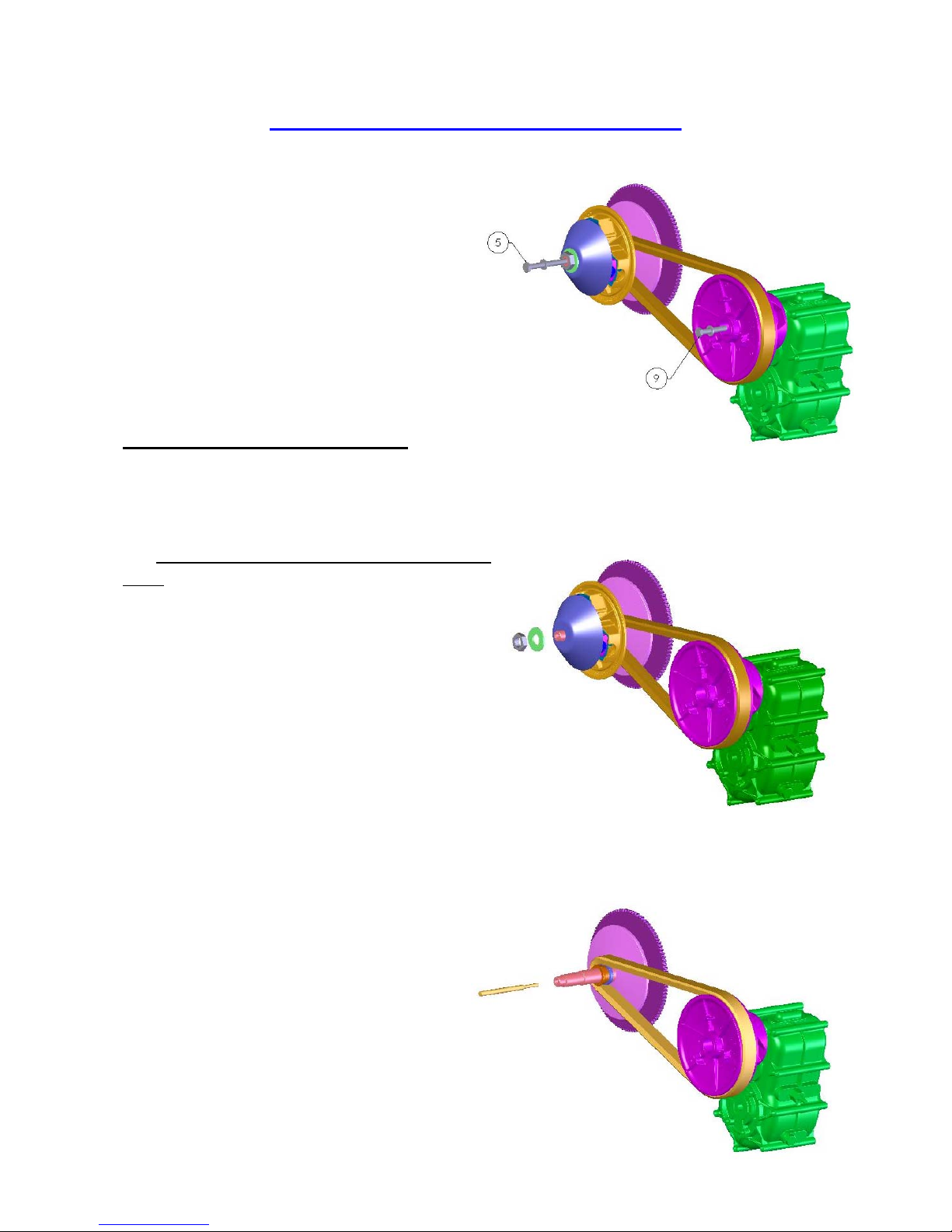
Removing the Pulleys from the Vehicle
Remove the bolt (5) from the drive pulley and
the bolt (9) from the driven pulley.
Removing the Drive Pulley
Remove the nut that holds the drive pulley in a closed position.
(use a 30mm bushing)
, Make sure you don’t drop the cap and the
units.
(It’s safer to remove the free parts, that is,
the parts that are no longer attached.)
Use an extractor that is appropriate for the threads at the end of the shaft (20 mm or ¾ inch).
Insert the extractor rod into the shaft of the
drive pulley.
6
Page 14
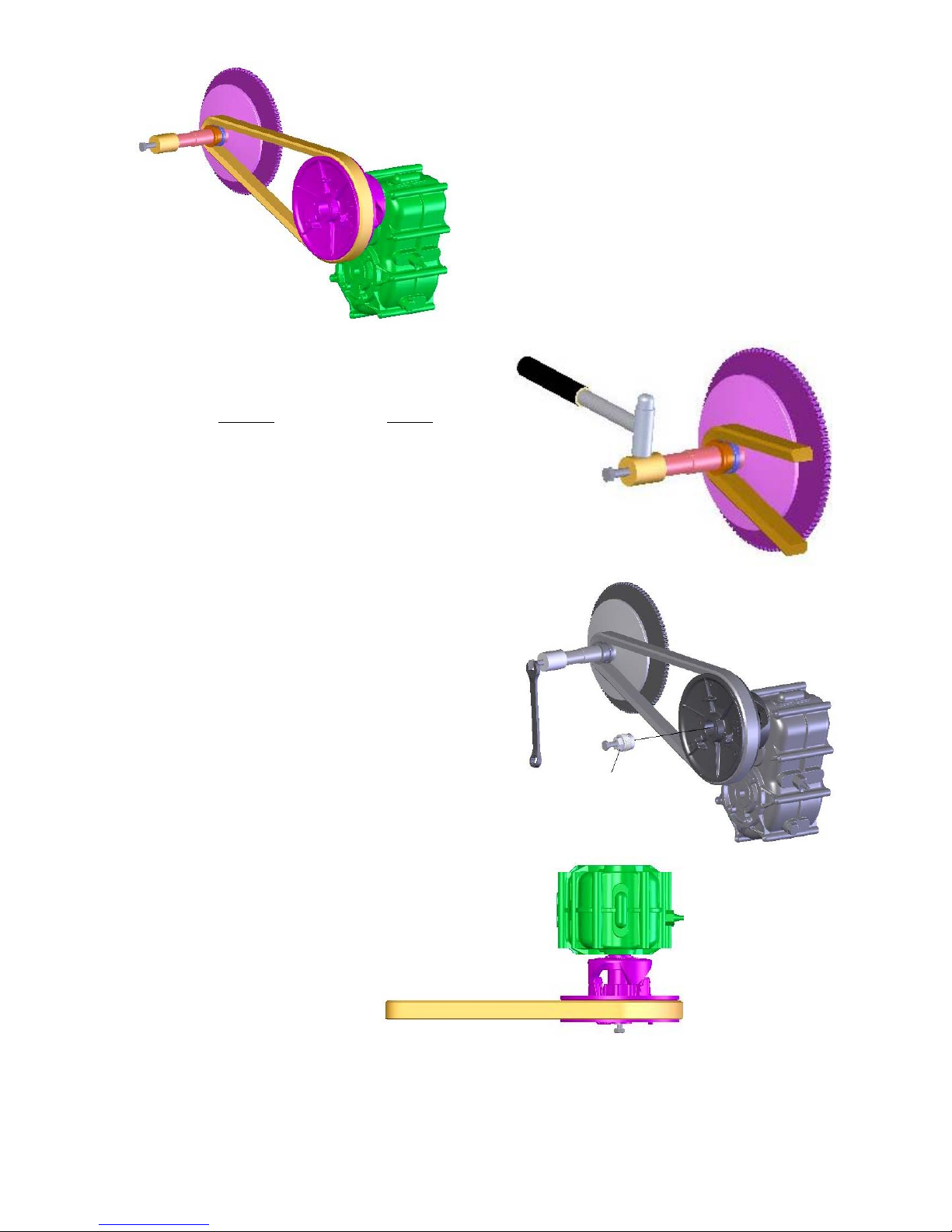
Sometimes, tapping the extractor gently with a
hammer can help free the shaft of the drive
pulley from the flywheel.
Bolt the extractor to the end of the shaft.
(Using pressure, turn one half turn).
Turn the bolt of the extractor until the pulley
pulls away from the shaft of the flywheel (1).
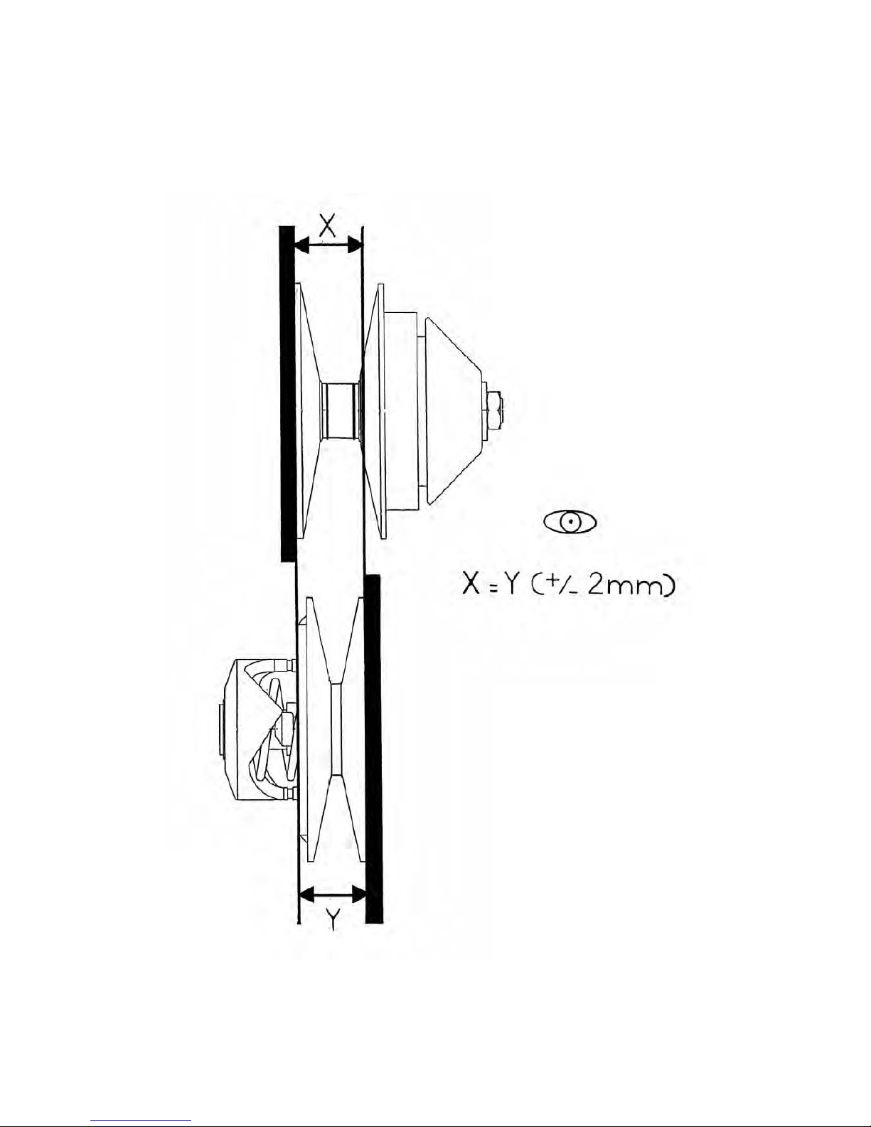
, Once you’ve removed the drive pulley, make sure
the drive belt can rotate in the same direction
as before you removed it.
Driven pulley
extractor
7
Page 15
Removing the Driven Pulley
The driven pulley can be removed manually but, in some cases, using the driven pulley
extractor can help.
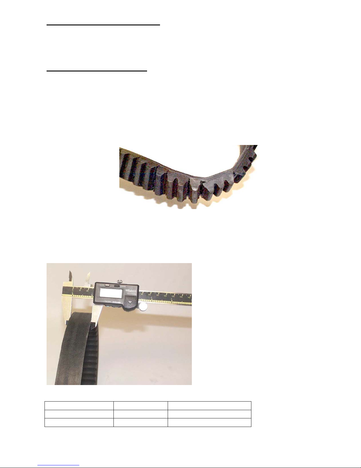
Inspecting the Drive Belt
L ,The drive belt has to be inspected to avoid damage that might cause
bodily harm and/or material damage.
• The drive belt must be replaced if you can see cracks in it when it’s turned inside out.
The drive belt has an original width that allows the transmission system to work properly.
It must be replaced according to the specifications in the table below:
Number starting with Original width Width at which to replace
B32-------- 29 mm 27mm
D32-------- 33 mm 31mm
8
Page 16
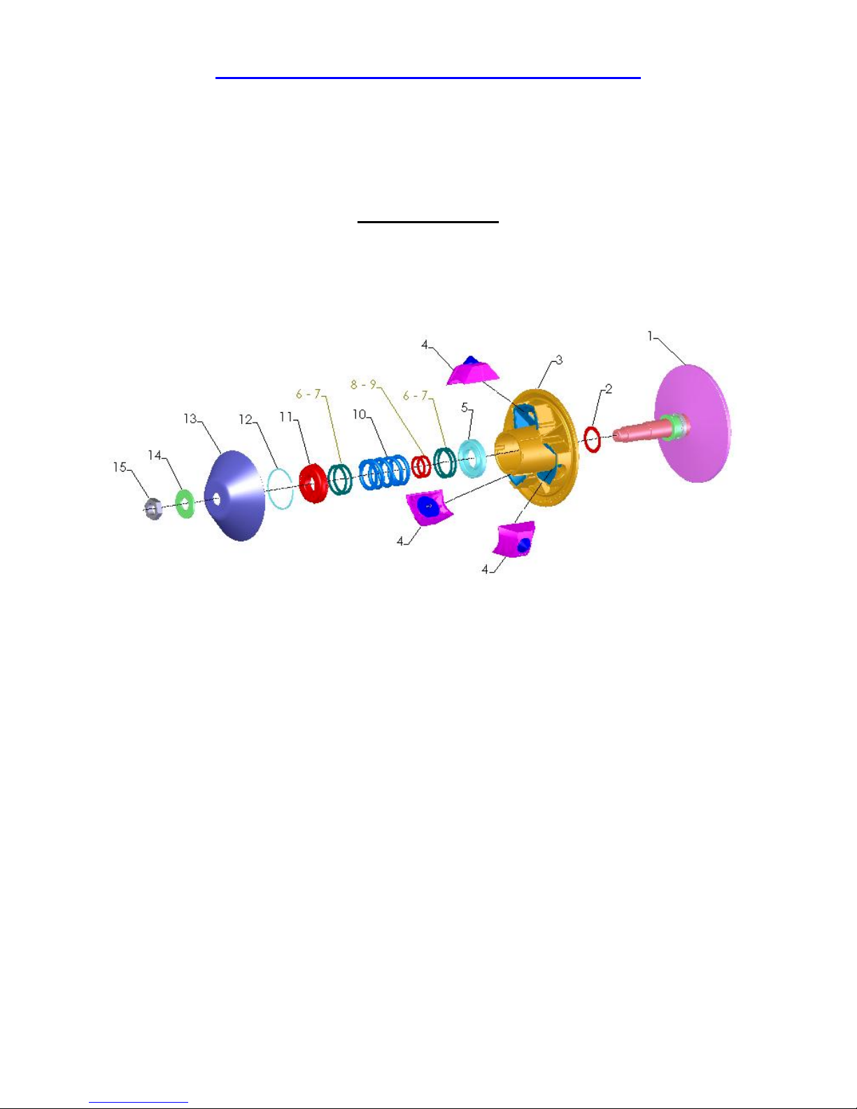
Disassembling and Reassembling the Pulleys
, When disassembling the pulleys, jot down the direction in which the drive belt rotates
to make sure it rotates in the same direction when it is reassembled.
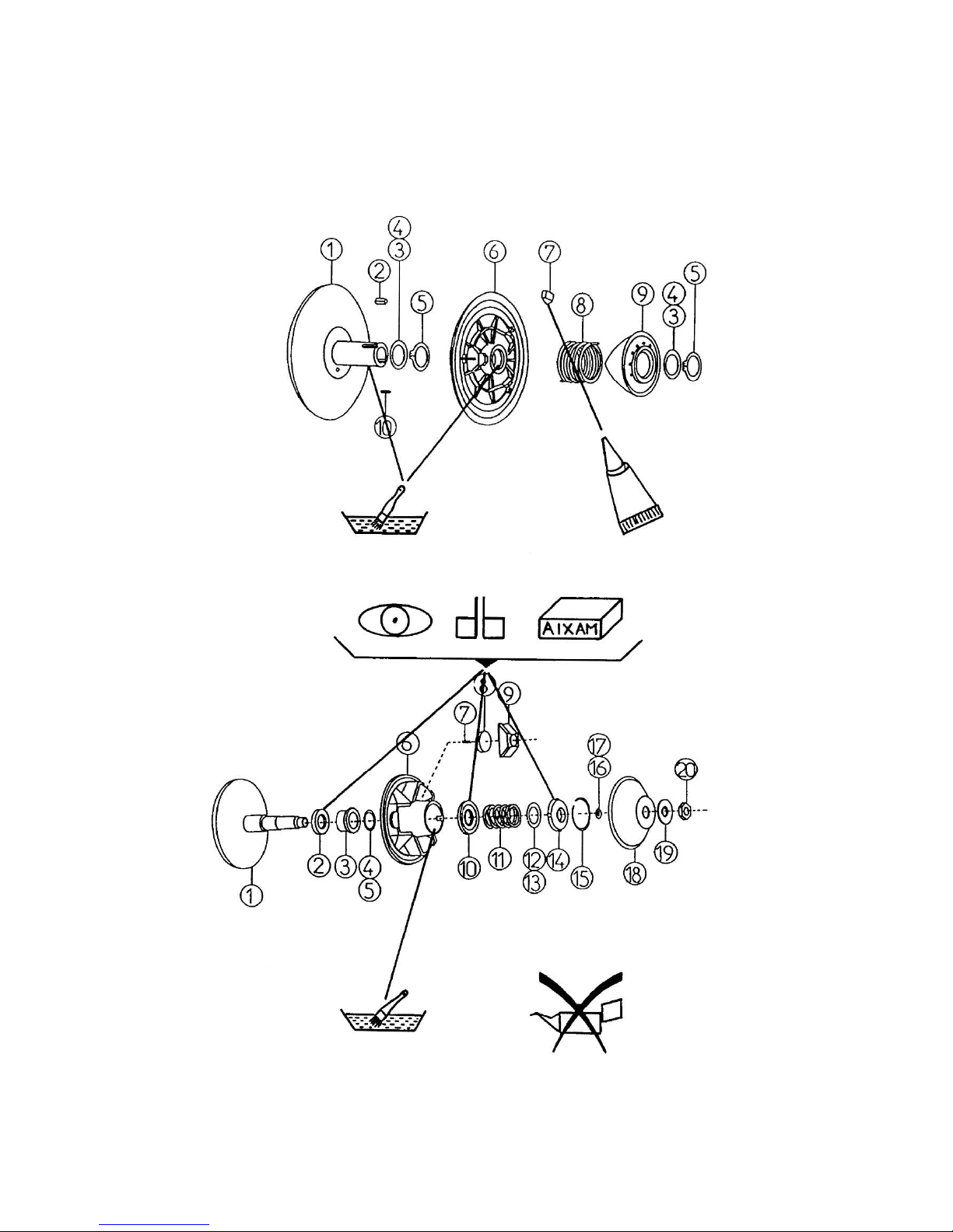
The Drive Pulley
1.... Stationary sheaf
2.... Spacing washer
3.... Sliding sheaf
4.... Assembled centrifuge unit
5.... Lower bearing
6.... Spacing washer (1.2mm)
7.... Spacing washer (0.68mm)
8.... Spacing washer (0.5mm)
9.... Spacing washer (1.0mm)
10.. Spring
11.. Upper bearing
12.. Retaining ring (washer)
13.. Cap
14.. Plate washer
15.. Nut
9
Page 17
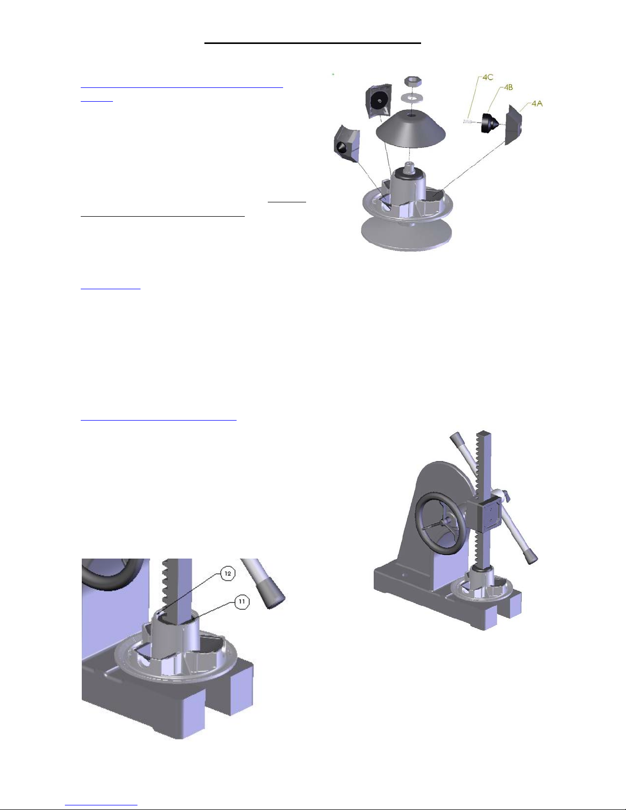
Disassembling the Drive Pulley
Disassembling the cap and the centrifuge
blocks
Remove the nut (15) and the washer (14).
This frees the cap and the centrifuge blocks.
L To make sure you don’t disturb the
balance of the pulley, mark the original
position of each centrifuge block so it can be
replaced in the same position when the
centrifuge is reassembled.
Inspection
• Damage to the units (4A)
• Condition of the anti-noise springs (4C) (on some models)
Disassembling the sliding sheaf
L Use a bench press (see illustration) or a drill press
to make sure the sliding sheaf doesn’t disassemble too
abruptly (it might jump apart like a spring).
Once you’ve removed the sliding sheaf from the shaft
of the stationary sheaf, position the stationary sheaf on
a press so you can lower the upper bearing (11).
Lower the upper bearing (11) so you can remove
the retaining ring (12) with a flathead
screwdriver.
10
Page 18
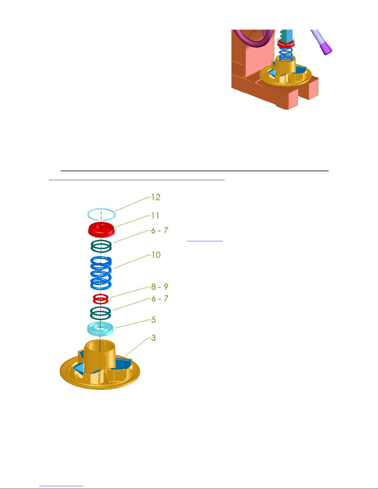
Slowly raise it again being careful not to let any of the parts
fall.
There may be several spacing washers inside the sliding
sheaf.
, Make sure you jot down the number of spacing washers (6-7) and (8-9) and their position
so that the original performance of the pulley is not altered.
For peak performance, make sure you clean the
sliding parts with a degreaser.
Inspection
• Wear damage to bearings 5 and 11
• Wear at the sliding sheaf’s working angle
• Wear damage to the spring (10)
11
Page 19
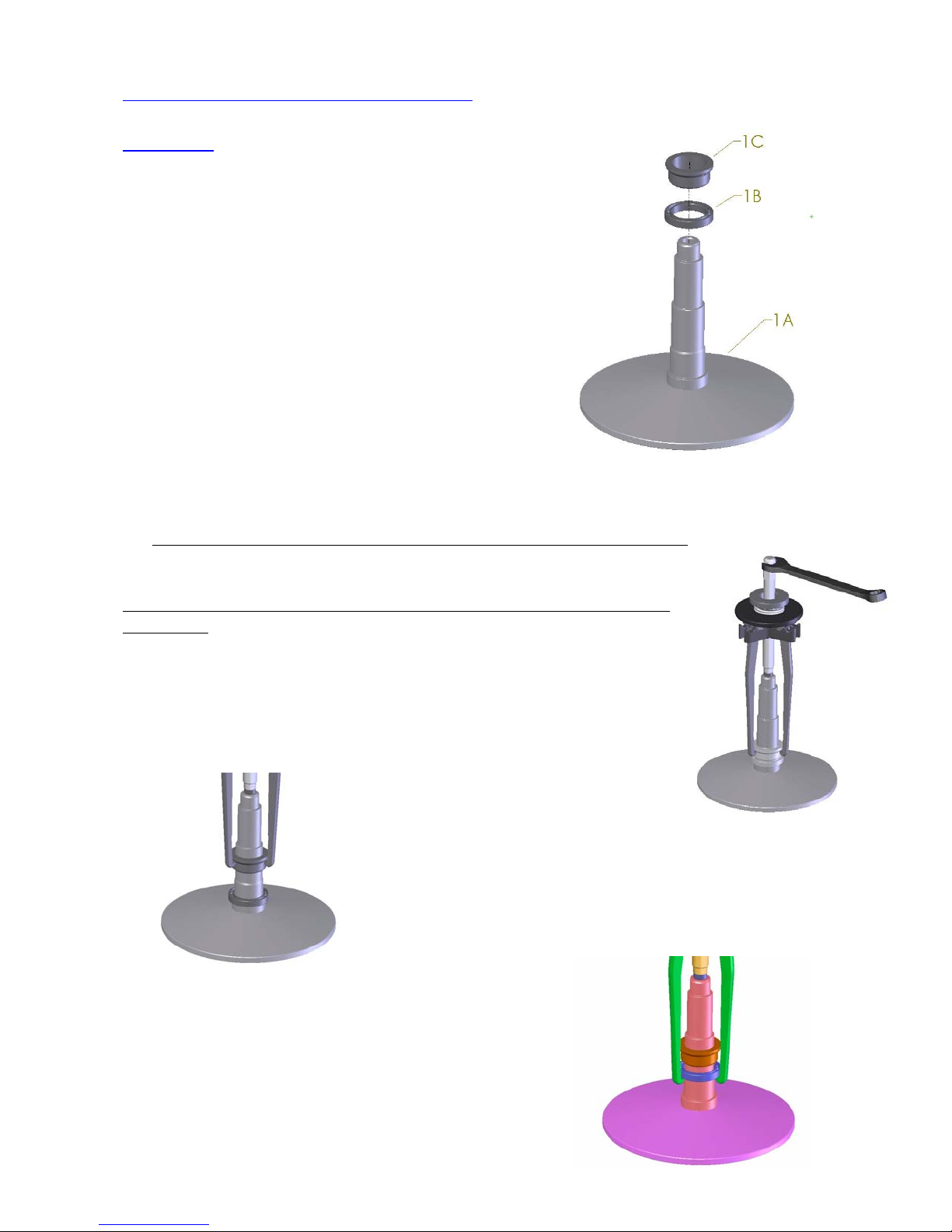
Disassembling the stationary sheaf (as needed)
Inspection
• Wear damage to the shaft (inside and out)
• Wear at the stationary sheaf’s working angle
• Replacing the bearing (1B), if necessary
1A Stationary sheaf
1B Bearing
1C Locking ring
, Before each part-removal step, make very sure you clean the shaft well.
Use an extractor so you won’t damage any of the parts that don’t have to
be replaced.
Removing the locking ring (1C)
Removing the bearing (1B)
12
Page 20
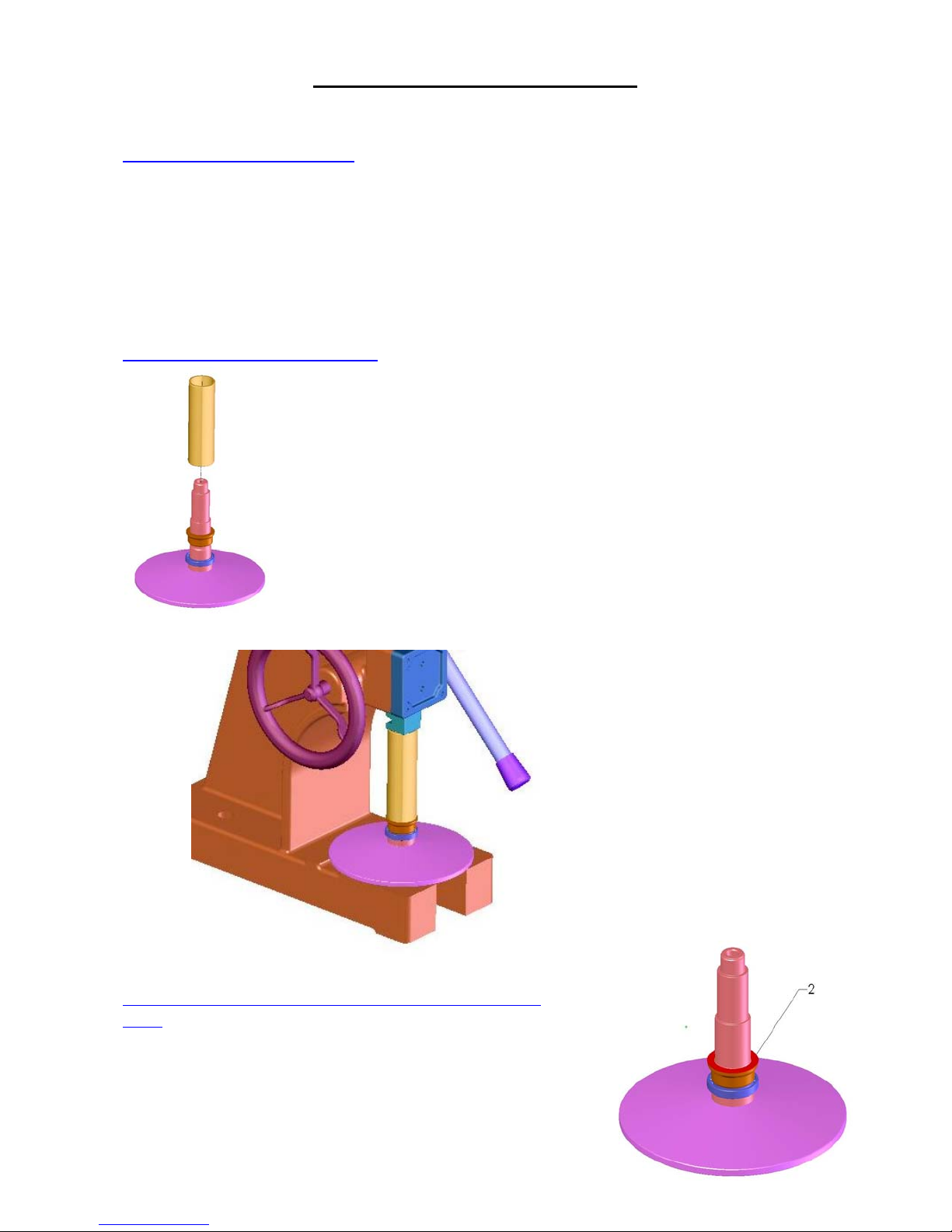
Reassembling the Drive Pulley
Reassembling the sliding sheaf
To reassemble the sliding sheaf, see the procedure “Disassembling the sliding sheaf” and
reverse the directions.
, Make sure you put the spacing washers back in their original positions.
Reassembling the stationary sheaf
Using a press and a tube (105mm long with an inner
diameter of 32mm), insert the bearing (1B).
Using the same tools, insert the locking ring (1C).
, Make sure the shoulder of the shaft, the bearing and the
locking ring make perfect contact with each other.
, Don’t use too much pressure with the press or you’ll
damage the components.
Mounting the sliding sheaf on the shaft of the stationary
sheaf
Before you mount the sliding sheaf (3) on the shaft of the
stationary sheaf (1), make sure you place the spacing washer
(2) on the shaft.
13
Page 21
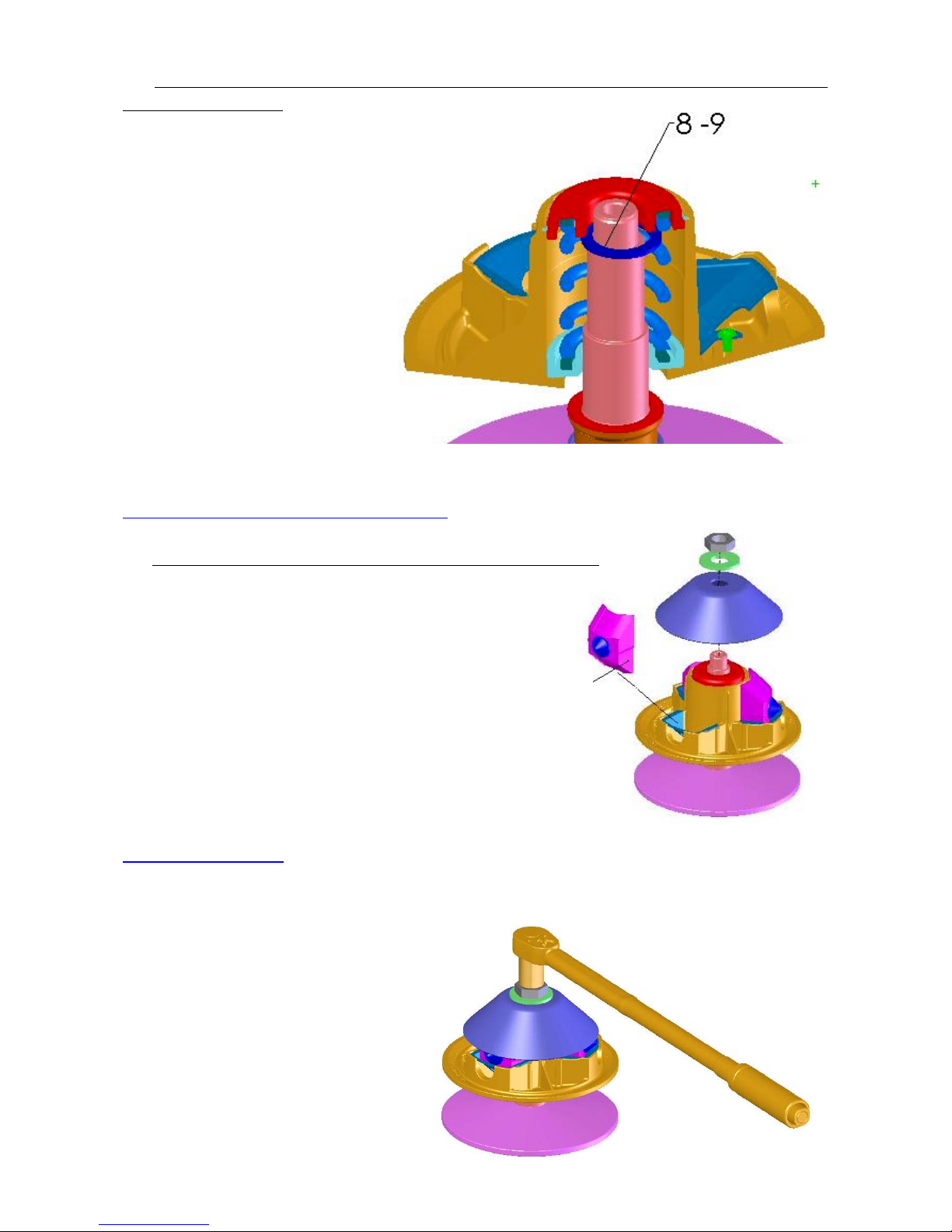
, When you mount the sliding sheaf (3), make sure you center the spacing washers (8-9)
properly on the shaft.
Mounting the cap and the centrifuge blocks
, Make sure you are mounting the centrifuge blocks correctly.
The narrow part of the block fits into the sliding sheaf.
Narrow side
Tightening the pulley
Use a torque wrench with a 30mm bushing to tighten the pulley.
, Use a tightening torque of 95 to
108 newton meters.
14
Page 22
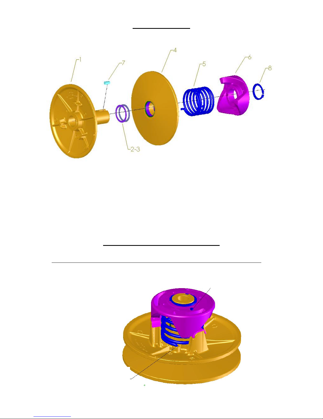
1.... Stationary sheaf
2.... Spacing washer (1.2mm)
3.... Spacing washer (0.68mm)
4.... Sliding sheaf
5.... Spring
6.... Cam
7.... Pin
8.... Retaining ring
The Driven Pulley
Disassembling the Driven Pulley
, Make sure you jot down the position of the spring on the sliding sheaf and the cam.
When you reassemble the pulley, the position of the spring must be the same as when
you disassembled it. This ensures that the performance of the pulley is not affected.
Position of the cam
Position of the
sliding sheaf
15
Page 23
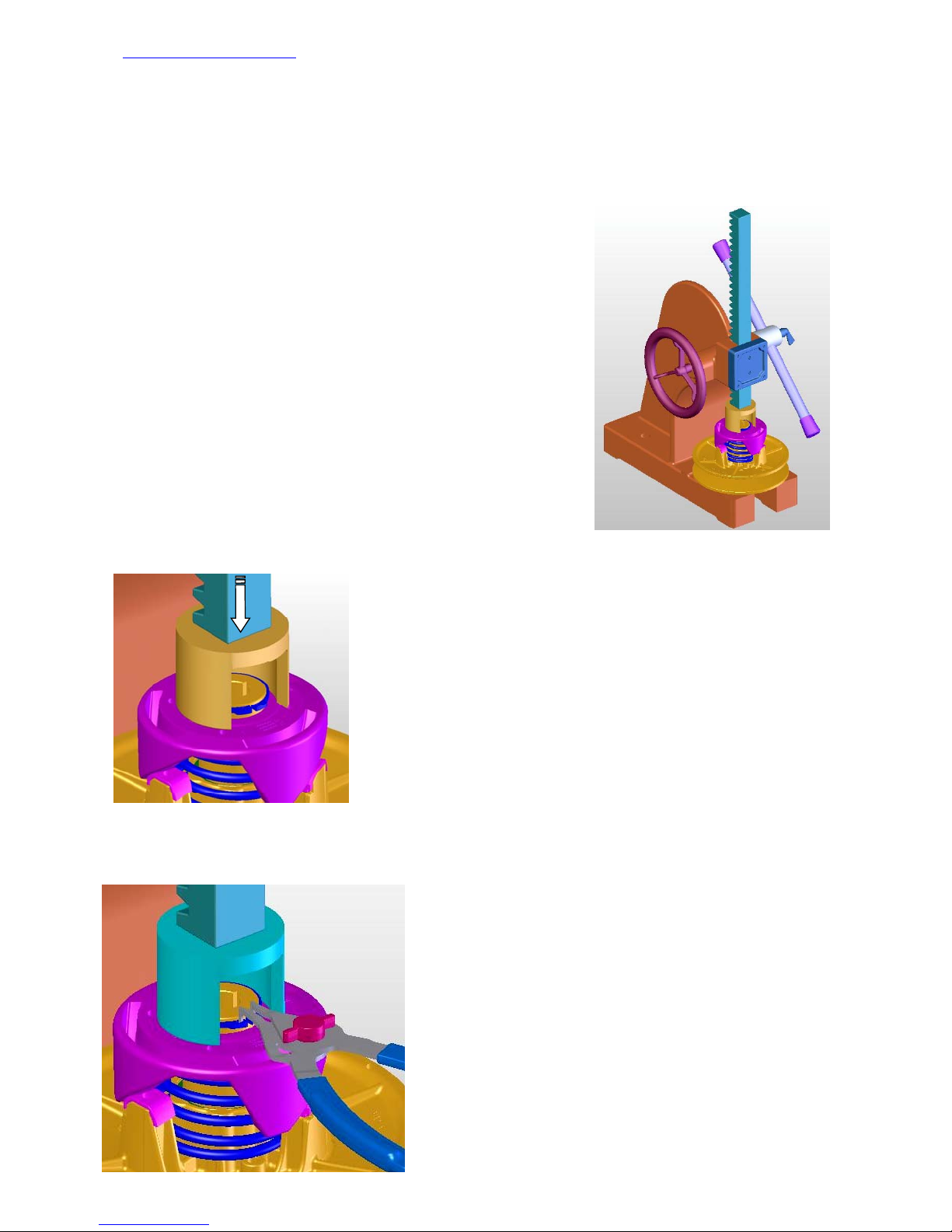
Disassembling the cam
L Be careful! A great deal of compression is used to mount the driven pulley. When you
disassemble it, it might jump up like a spring (spring effect).
To make sure you disassemble the driven pulley safely, use a press or a driven pulley
dismantling tool.
The pulley has to be blocked so it won’t turn. Also, it is
recommended that the pulley be stabilized on the press to
keep it from moving during the different disassembling
steps.
Push on the cam to free the retaining ring (maximum 2
or 3mm)
Remove the retaining ring with an appropriate pair of
pliers.
16
Page 24
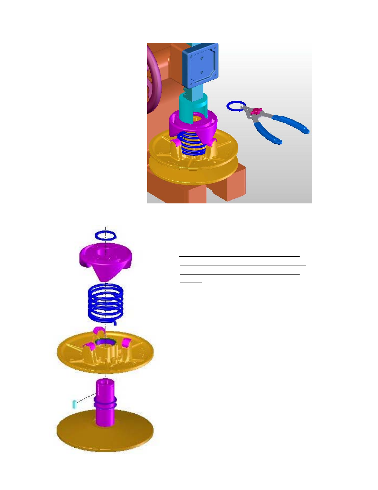
Carefully lift the cam to free it from the shaft.
,Jot down the number of spacing washers
between the two sheaves to ensure that the
original performance of the pulley is not
altered.
Inspection
• Wear damage to the cam
• Wear damage to the spring
• Visual inspection of the components
17
Page 25
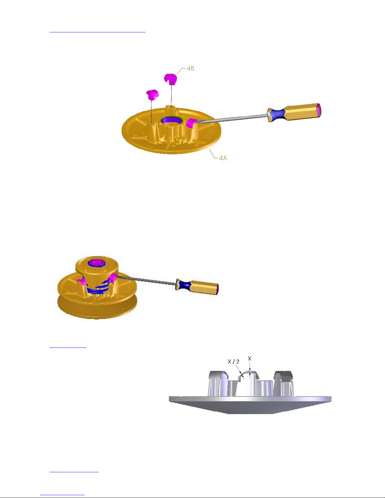
Disassembling the sliding sheaf
You can remove the cam fittings with a flathead screwdriver.
4A....Sliding sheaf
4B....Cam fitting
_______________________________________
You can also remove the cam fittings without disassembling the pulley.
• Making sure the stationary sheaf doesn’t move, twist the sliding sheaf.
• Use a flathead screwdriver to remove the shoes.
L Be careful not to get a finger jammed when handling the shoes.
You should use a pair of long nose pliers.
_______________________________________
Inspection
• If the cam fittings (4B) are worn by half
the original thickness (X) (see illustration),
replace them.
• Wear in the sheaf’s working angle (4A)
• Wear to the inside bearings of the sheaf
(do not replace unless the sheaf has wear damage)
For peak performance, make sure you clean the inside bearings with a degreaser.
Stationary sheaf
18
Page 26
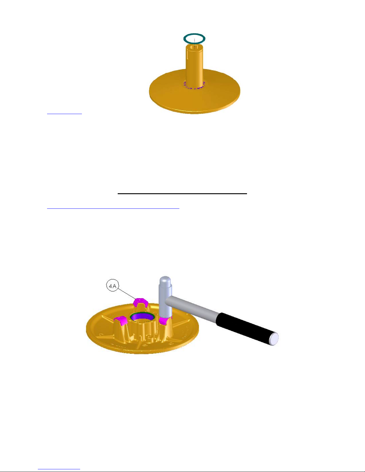
The stationary sheaf (1) cannot be disassembled without damaging the parts. All you can
do is inspect it.
Inspection
• Wear damage to the shaft (inside and out)
• Wear to the sheaf’s working angle
• Visual inspection
Reassembling the Driven Pulley
Mounting the cam fittings on the sliding sheaf
Use a hammer to mount the cam fittings (4A).
, Don’t be too rough with the hammer. You might damage the fittings.
19
Page 27
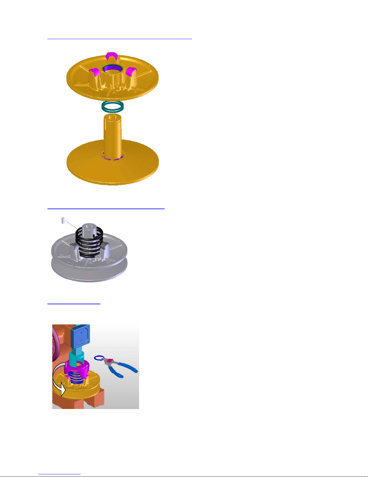
Mounting the sliding sheaf on the stationary sheaf
Mounting the spring on the sliding sheaf
, To make sure the pulley works properly,
remember to put back between the two
pulleys as many spacing washers as you
removed when you disassembled it.
, Place the spring in the sliding sheaf (4) in the same
position as when you disassembled it.
Place the pin (7) on the shaft of the stationary sheaf (1)
Mounting the cam
To mount the cam (6), use the disassembling procedure in reverse.
• Place the spring in the cam in the same position as when
you disassembled it.
• Lock the cam into position on the stationary sheaf (1)
and on the pin (7).
Turn the sliding sheaf (4) counter clockwise one third (1/3) of a turn.
• Lower the cam to lock the cam fittings in place (4B).
• Install the retaining ring (8).
• Keep the stationary sheaf and the cam (6) from moving.
20
Page 28
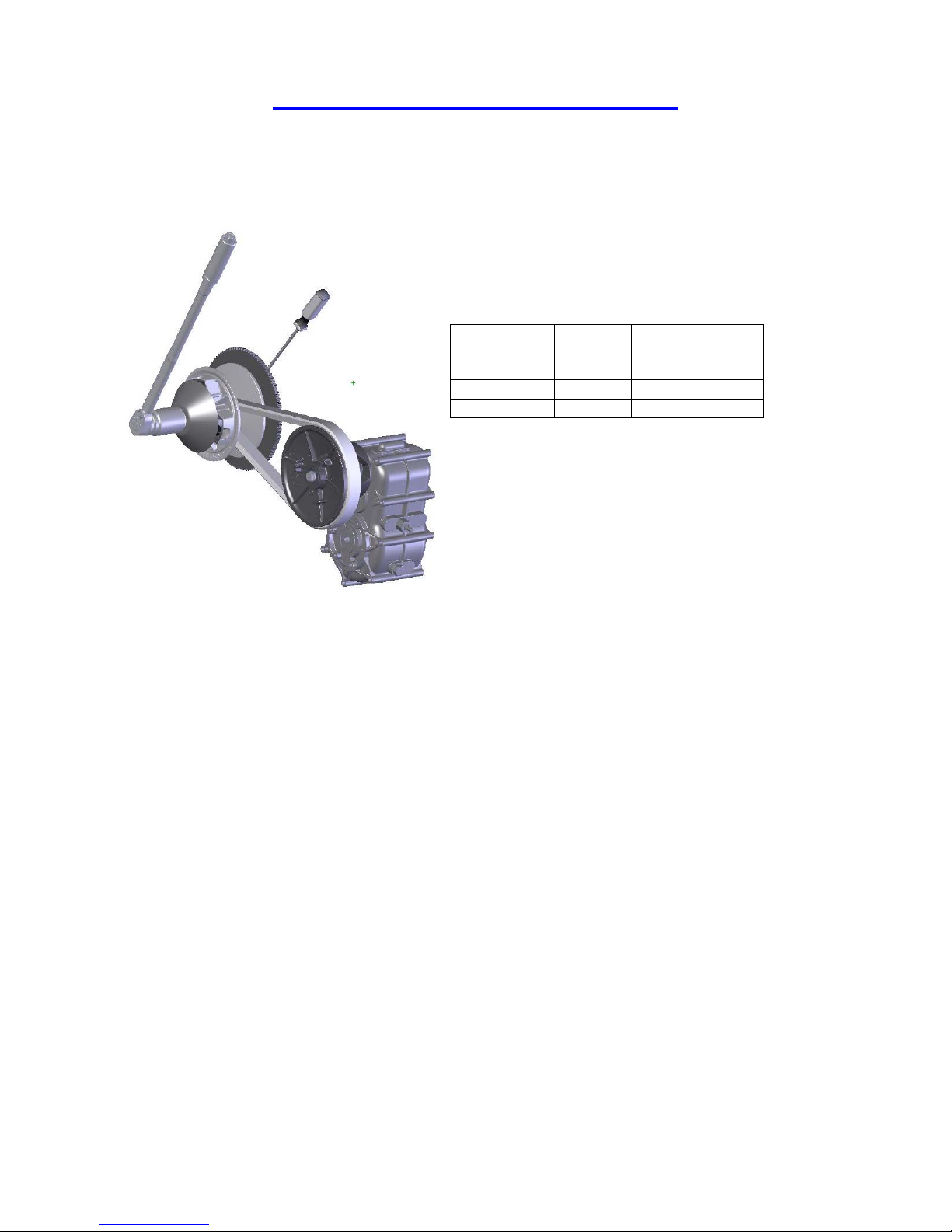
Reinstalling the Pulleys on the Vehicle
Once the pulleys and the drive belt are properly installed, use a torque wrench
(standard torque) to tighten the two bolts.
Minimum
diameter of
the bolt
8 mm 8.8 21 to 28
10 mm 8.8 42 to 54
Grade Standard torque
(newton meter)
To tighten the drive pulley, use a screwdriver or other tool to block the engine
from turning. Be careful not to damage any of the parts.
21
Page 29
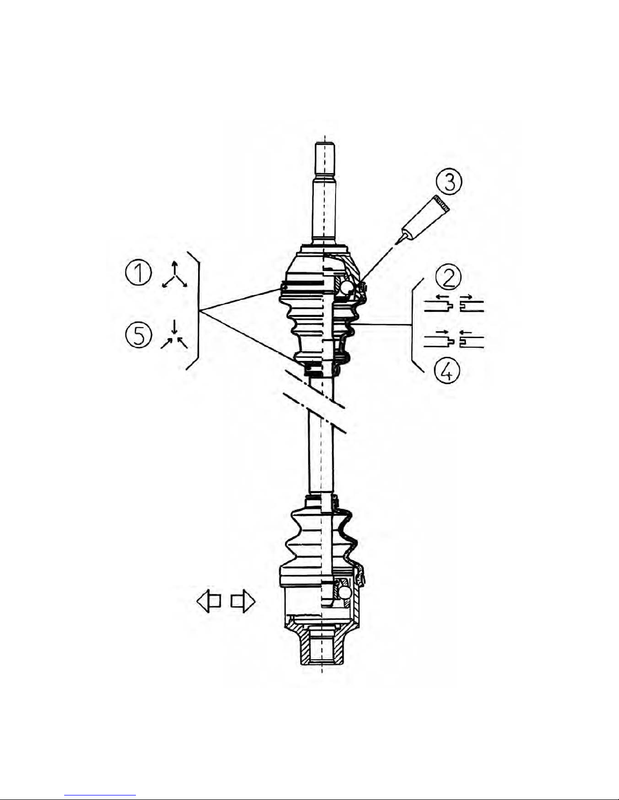
Drive line
Page 30
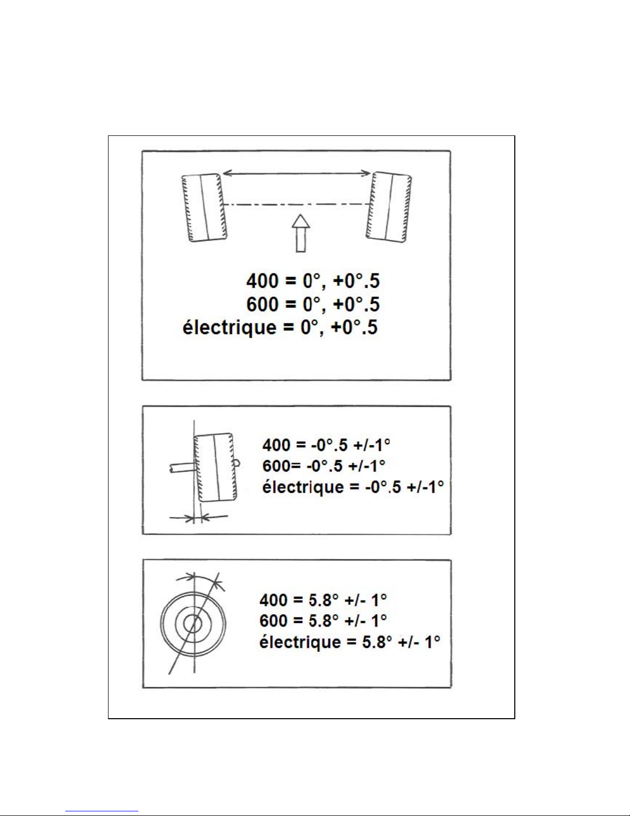
GROUPE 4
Front Axle
Page 31
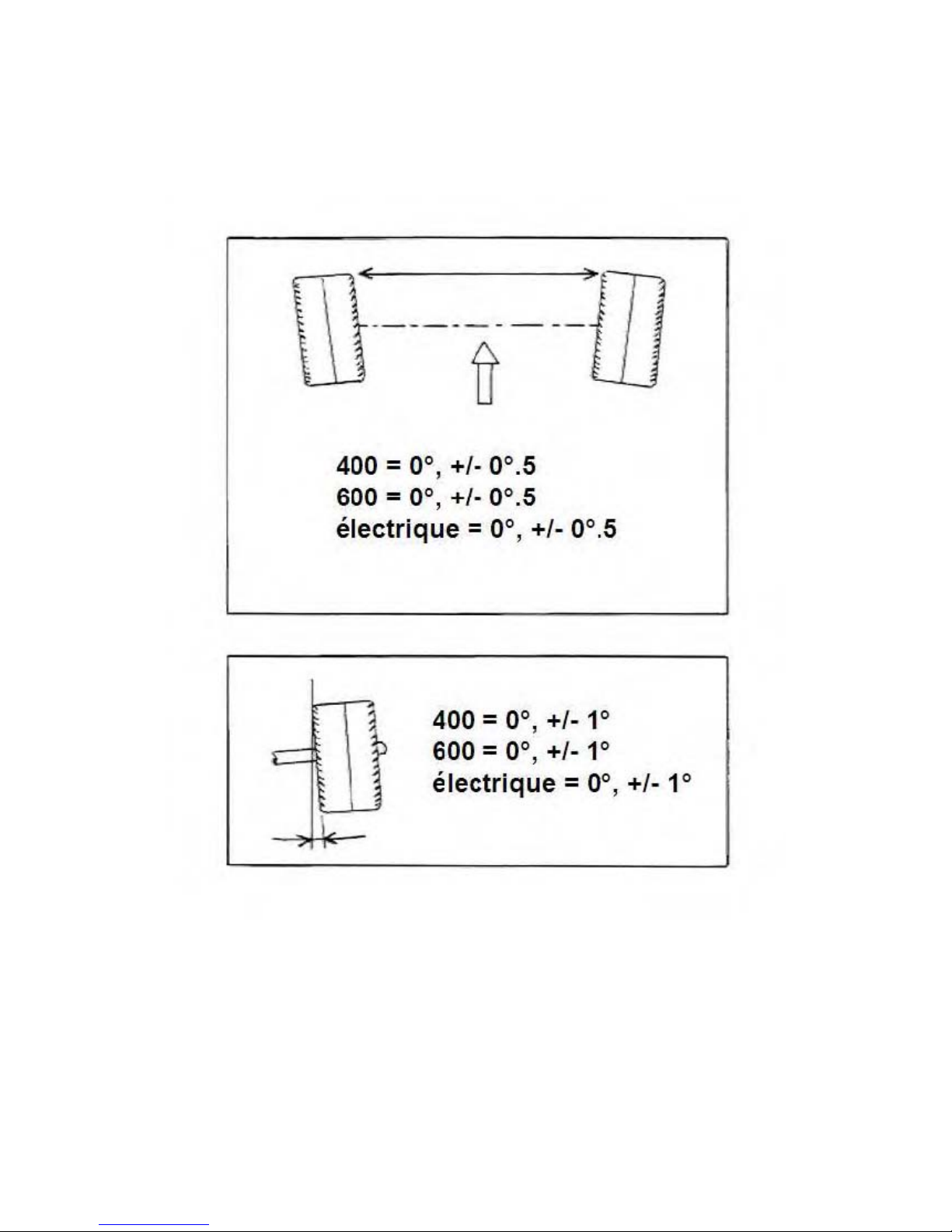
GROUPE 5
Rear Axle
Page 32
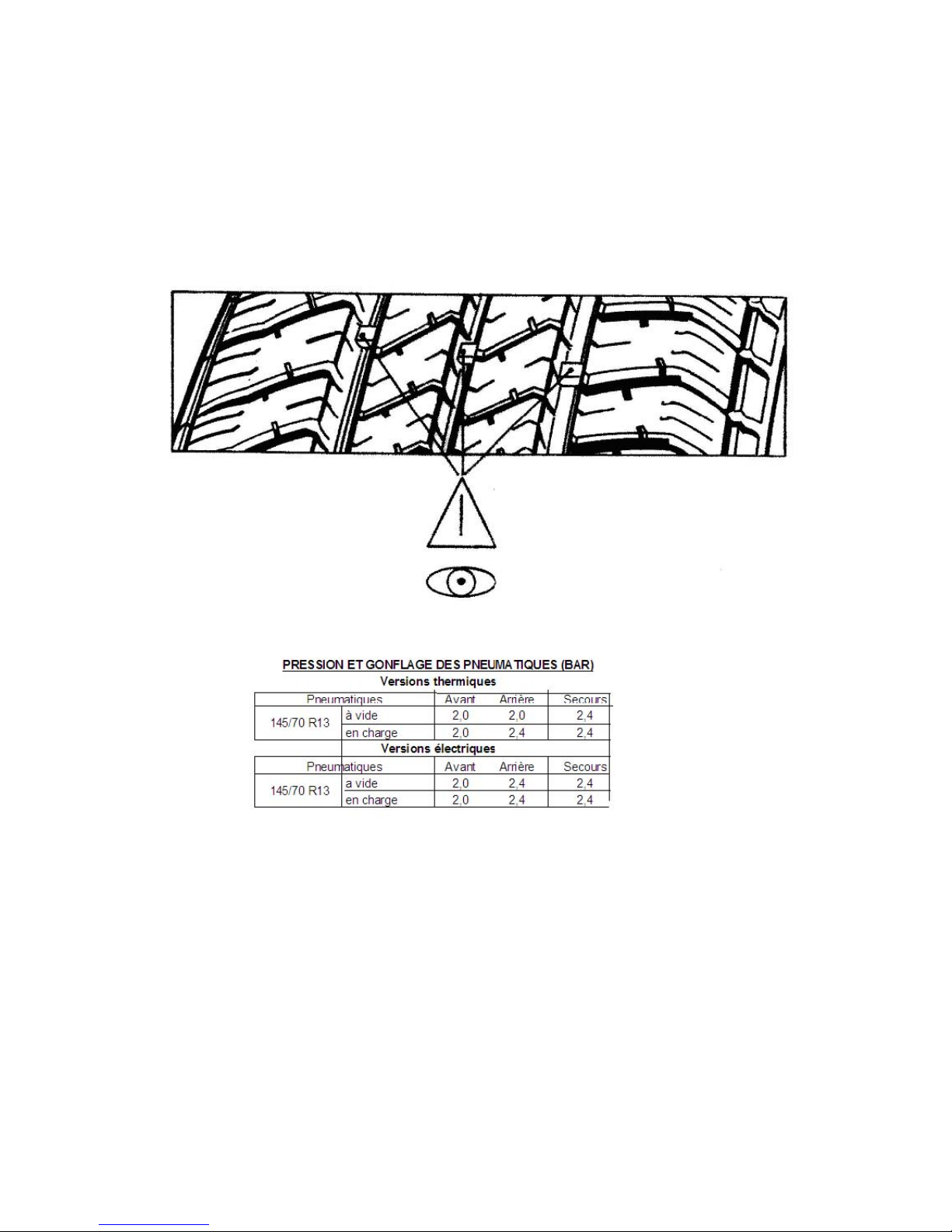
GROUPE 6
Wheel
Page 33
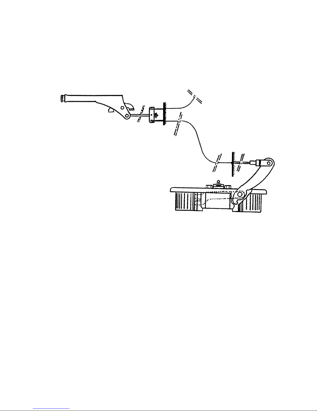
Handbrake
Page 34
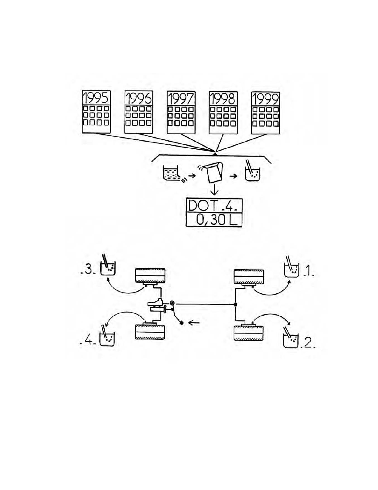
Brake
Page 35
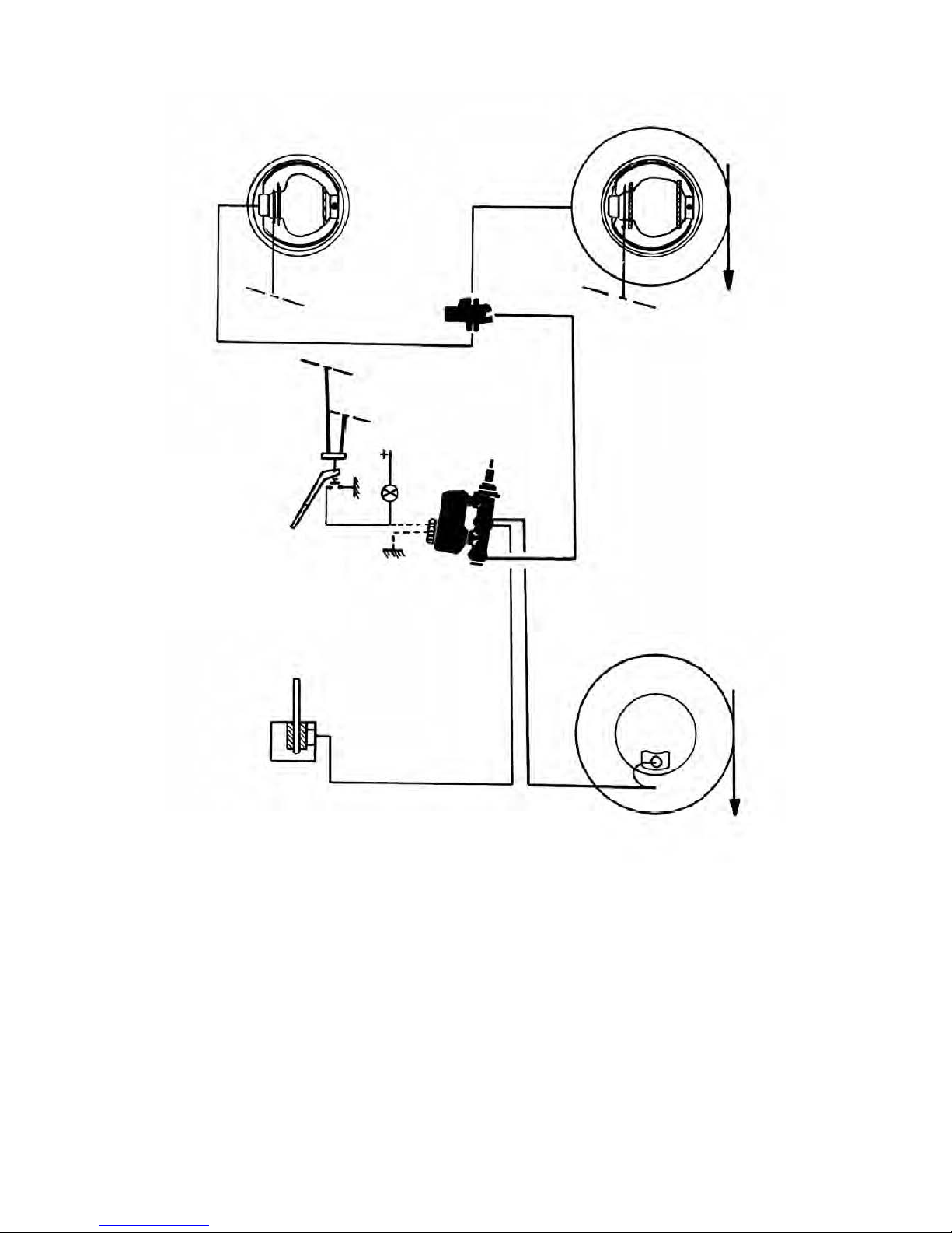
Page 36
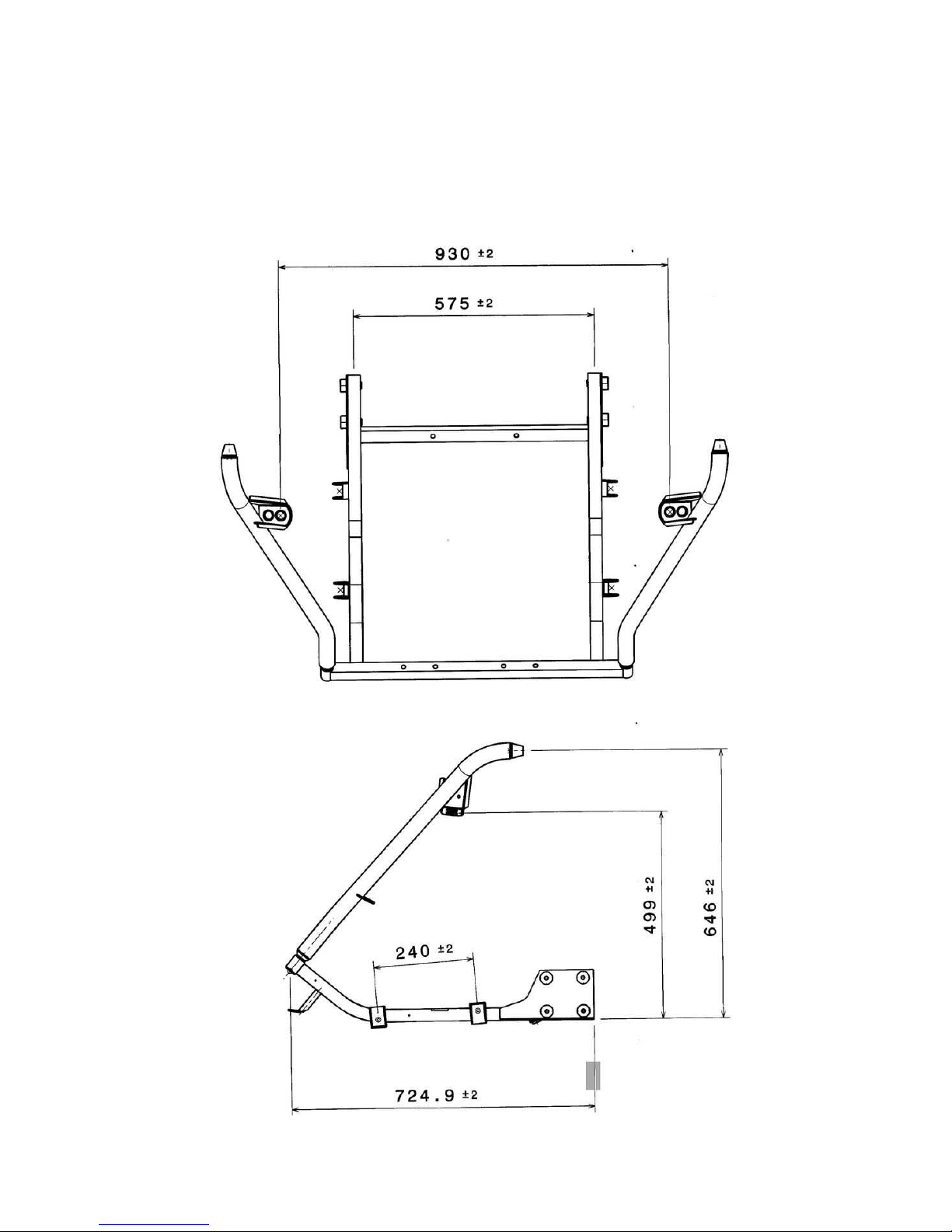
GROUP 7
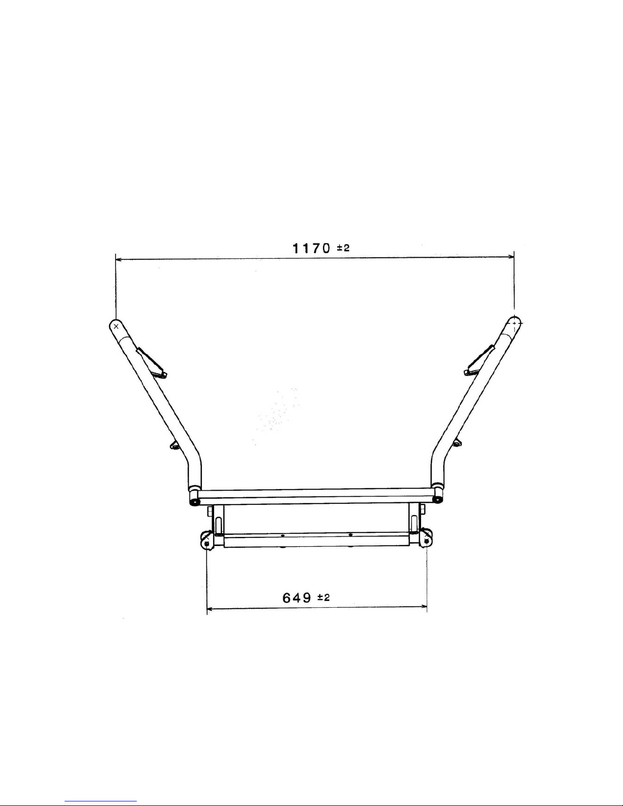
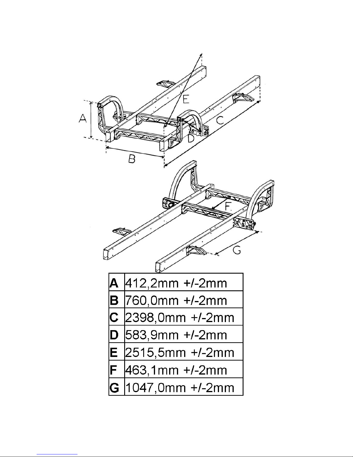
Body shell and sub frame
Page 37
Page 38
Page 39
GROUP 8
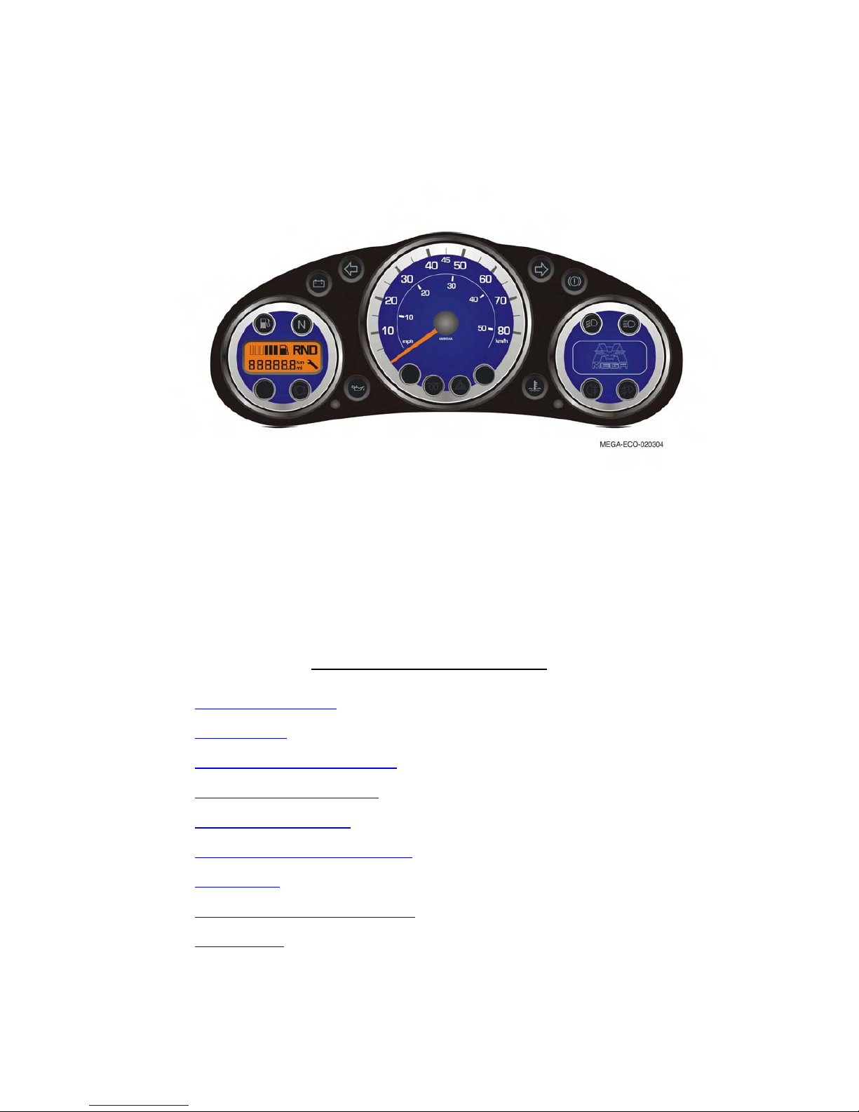
This display is only fitted on the Mega Multitruck (except Electric Vehicle).
You can read the reference AM8K06A under the needle.
Display functionality features
1) Analogical speedometer
2) LCD fuel gauge
3) LCD Odometer (daily and general)
4) Gearbox position LCD indicator
5) LCD Service indicator light
6) Turning light, hazard light and buzzer
7) Indicator lights
8) Pre heating system and indicator light
9) Stop managing
Page 40

1-Speedometer
The speed signal is delivered by a Hall Effect sensor fitted on the gearbox case.
The sensor sends 8 pulse per revolution.
The sensor is driven by the intermediary shaft of the gear box and the display convert the
electric signal to the needle control.
It’s a linear progression from 0 km/h to maximum speed.
Maximum speed shown for a L6e (QLeM) = 80 Km/h
Maximum speed shown for a L7e (QLoM) = 120 Km/h
When the ignition is off, the needle goes to 0 Km/h
2-Fuel gauge
Analogical signal from the tank sensor (potentiometric sensor)
The fuel level is displayed by a bar graph (6 bar) and a minimum indicator light.
Low level = Blinking of the last bar and lighting of the minimum indicator light.
3-ODOMETER (Daily and general)
The speed sensor gives the speed signal to the display; the display calculates the mileage for the
odometer according to the wheel diameter and gearbox ratio.
Odometer is a LCD display with 6 number and 1 decimal place et 1 point décimal.
Maximum value for the main odometer = 999 999 Km
Maximum value for the daily odometer = 999.9 Km
You can switch from the main odometer to the daily by a short push on the left button.
Reset the daily odometer by a long push on the left button when the daily odometer is displayed.
The speed unit is located at the right of the odometer.
To switch from Miles to Kilometre =
- Push on the left button
- Put the ignition ON
The Unit will automatically change. (Repeat this process to change again)
4-Gear box position indicator
It is managed by the two sensors on the gearshift lever.
Lever on the N position = N is displayed by the LCD and N indicator light is lighting
Lever on the D position = D is displayed by the LCD
Lever on the R position = R is displayed by the LCD
Page 41

5-Service management
How much distance has been covered since the last service. Calculated with the
odometer.
First service = 1000Km or 1 year
Normal service 5000Km or 1 year
When the ignition is on, you can see the distance to the next service during 5 second, it is
displayed instead of the odometer with a little symbol (key) .Afterward the odometer came back
and the key symbol disappear.
If the distance to the next service is less than 200 Km, the distance displayed will blink for 5
second and after the key symbol will stay on.
If the time to the next service is less than 20 days, the message “1 year” displayed will blink for 5
second and after the key symbol will stay on.
When the time to the next service is completely past, the message “1 year” is displayed for 5
second and the key symbol will stay on.
To reset the service management:
- Put the ignition on
- Push on the two buttons for 6 second until 10 second after the ignition is
on.
6-Turning lights and hazard lights
Turning lights management and right and left display indicator management. .
In good order: 100 blinking per minute.
With a broken bulb: 200 blinking per minute.
Turning lights are only available when the ignition is on, hazard light are always available.
The buzzer works with the hazard and turning lights.
The buzzer will also advise you if the lamps are on when you want to leave the vehicle:
- The ignition must be off
- The lamp must be on
- The door must be open
7-Indicator lights and hazard lights
Indicator lights managed by the display:
Low beam lamp
Hi beam lamp
Charging system defect
Low oil pressure
High cooling system temperature
Brake pad wear
Handbrake and low brake fluid level
Page 42

8-Pre-heating
When the ignition is on, the display managed the pre-heating system and the
pre-heating indicator light.
When the ignition is off, the pre-heating system and the indicator light are switching off by the
display.
The pre-heating time depends of the engine temperature, drive by a CTN sensor.
If the CTN sensor is unplugged, 0°c is taken to estimate the pre-heating time.
9-Engine Stop
When the ignition is switched off, the engine stop solenoid is fed for 8 seconds by a timing relay.
Page 43
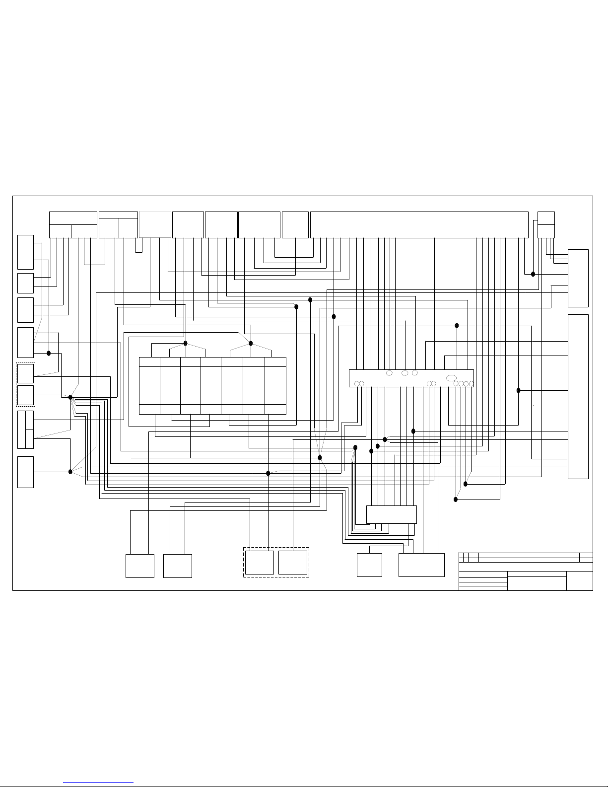
Client
G
1
06-11-06
Voir émail le 6 novembre 2006 Objet: EVO 8MD041
M3
M2
Dess par:Nouha Koubâa
Rév
Echelle:
Vérifiée par: Abdellatif Jardak
Ind
Date:
Réf: 8MD041
date
1:1
26-07-2006
Site web:www.sidilec.com.tn
Tél. 00 216 74 83 25 10 Fax. 00 216 74 83 25 10
ROUTE DE MAHDIA KM 10 3054 Sfax (Tunisie)
Objet de la modification
International
Sidilec
Origine
Essuie
glace
Eclairage
Plafonnier
4
1 53
2
C19
C28
E1
+ PER
C13A
C60-Anti
Brouillard
A B
C6 - Contacteur
point neutre
A B
C5 - Contacteur
feux de recul
Plan électrique PDB
E3
E4
E14
E13
C27
C36
+PER
EM2
Masse
E2
Feux de route
Feux de Croisement
Feux de position
Avertisseur
Clignotant droit
Clignotant gauche
a1 b1 b2 B2 B4 A5
Commodo feux
B3 B5 b3 a3 A2 A4 B1
Anti brouillard
M8
E7
E8
E5
E10
Masse
Cde lave glace
M1
+ PER
+ APC
Feux de route
Feux de Croisement
Feux de position
Clignotant droit
Clignotant gauche
Anti brouillard
warning
Masse
Capteur de porte
Frein à main+looked
Clignotant droit
Clignotant gauche
Code relai de préchauffage
Arrêt moteur
Jauge carburant
Masse carburant
Point neutre
Thermo contact
Charge alternateur
Plaquette de frein
Pression d'huile
Températeure d'eau
Capteur de vitesse masse
Alim capteur de vitesse
Capteur de vitesse signial
3 4 7 14 13 6 20 9 12 5 1 2 28 15 7 8 5 6
21 23 10 3 17 14 25 12 13 4 29 27 18 2
COMBINE DE BORD C37 C38
- Combiné de
bord
- Allume
cigare
- Auto radio
- Feux code,
position, route,
clignotant, anti
brouillard
- Avertisseur
sonore
- Plafonnier
- Dégivrage
ar
- Arrêt moteur
Préchauffage
- Ventilateur
chauffage
- Essuie glace
av et ar
- Feux de recul
-Combiné de
bord
- Relai de
Dégivrage ar
- Feux stop
- Relai de
préchauffage
- Alternateur
F3 (15A)
F2 (20A)
F1 (20A)F10 (20A)F9 (20A)F8 (15A)F7 (10A)
C19- S1 C19- S2 C19- S3 C19- S4 C18- S1 C18- S2 C18- S3
+ APC + APC + APC + APC + PER + PER
+ PER
C18- E3C18- E2
C18- E1
4 C19- E4
C19- E3
C19- E2C19- E1
Anti Buillard
Feux ar
Feux de recul
Masse
Frein à main
Masse carburant
Jauge carburant
Masse
1 9 3 8
C10 - warning
Eclairage
Masse
+PER
C11 - Allume
cigare
1 2
C12 - Allume
cigare
E6 E8 E5 E3 D2 D4 D3
C1- Interconnection Moteur/ Tableau de bord
+ APC
E12M
intermittant
vitesse1
vitesse2
B6 B5 B1 B2 B3 A6
C26- Commodo essuie glace
E9
EM1
Masse
Cde plafonnier
M5
C2 -
Exitation Dém
+ ACC
+ APC
Code Relai
Bougie
+ PER
+ PER
Code Relai
Bougie
Ventilateur vitesse 1
Ventilateur vitesse 2
Ventilateur vitesse 3
+ APC
Ventilateur vitesse 3
Ventilateur vitesse 2
Ventilateur vitesse 1
+ APC
Exitation Démarreur
Arrêt moteur
Capteur de vitesse signial
Alim capteur de vitesse
Capteur de vitesse masse
Températeure d'eau
Pression d'huile
Thermo contact
Clignotant droit
Charge alternateur
Plaquette de frein
Avertisseur
feux de Croisement
feux de Route
feux de Position
Clignotant gauche
Niveau looked
Cde lave glace
A3 A5 C6 C7 C8 C5 C9 C4 B8
A2 A6 A1 A7 B1 A9 B2 B4
B7 B6 B5 A8 B3
C24 - Interconnection Moteur / tableau de bord
C25-Bougie
de
Préchauffage
1 4 3 2
C9 - Inter ventilateur
C16-Relai arrêt
moteur
3 2 1 5 2 3 1 5
C15-Relai de
Préchauffage
3 2 1 5
C14-Relai de
demarrage
C21 - GR
1 2
Neiman
C22- NO
1 2
+Bat
+ APC
+ ACC
Masse
+ ACC
+PER
8 7 4
Batterie
C3 +
C6- Masse
chassis
C32
Connecteur
de porte
gauche
C31
Connecteur
de porte
gauche
C7- Allimentation
Auto radio
3 2 1
C8 - HP
6 5 4 3
C13-
Plafonnier
C29
HP G
C4
HP G
Page 44
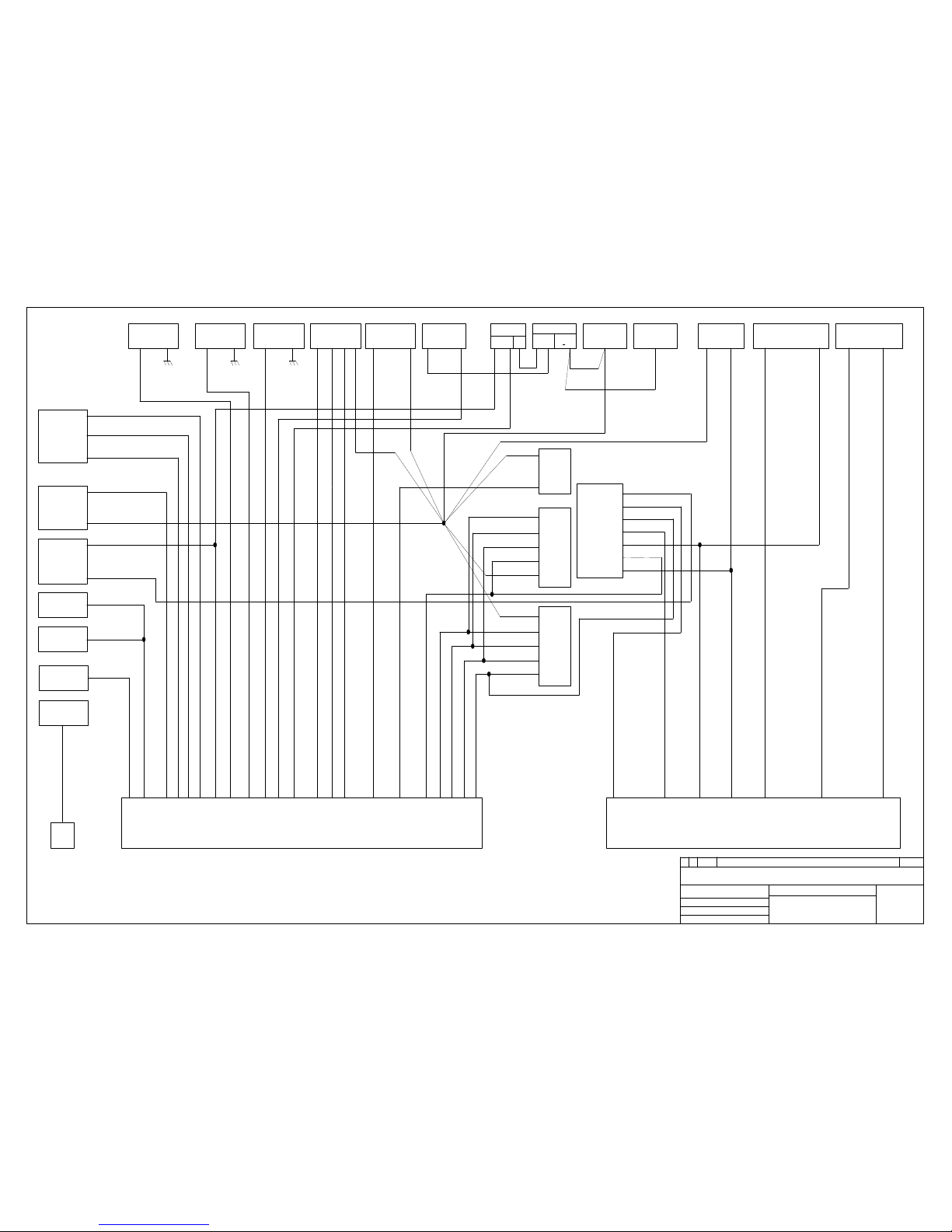
Plan électrique Fx MoT MW6
Origine
Sidilec
International
Objet de la modification
ROUTE DE MAHDIA KM 10 3054 Sfax (Tunisie)
Tél. 00 216 74 83 25 10 Fax. 00 216 74 83 25 10
Site web:www.sidilec.com.tn
26-07-2006
1:1
date
Réf: 8MD043
Date:
Ind
Vérifiée par: Abdellatif Jardak
Echelle:
Rév
Dess par:Nouha Koubâa
V
H
E9
E8
C31'
Reprise masse
7 Recul
3 Clignotant D
2 Masse
5 Anti brouillard
6 Clignotant G
1 Feu arriere
4 Stop
C30
Interconnexion
Faisceau moteur
Faisceau arrière
C30A
Option de recul
E3
E7
E4
E5
E6
Feux de route
Feux de croisement
C17
Feux AV
G
1 4 5 6 3
Masse
Feux de position
Clignotant av G
Masse
Clignotant av d
Feux de position
Feux de route
Feux de croisement
4 5 6 3 1
C13
Feux AV
D
C20 Niveau
looked
A
B
EPM
E2
Bougie de préchauffage
Ventilateur vitesse 3
Ventilateur vitesse 2
Clignotant av gauche
Feux de position
Feux de route
Feux de croisement
Clignotant av droit
Niveau looked
Pompe lave glace
Ventilateur vitesse 1
Charge Altemateur (TDB)
Exitation démarreur
Thermo contact (TDB)
Température d'eau(TDB)
Pression d'huile (TDB)
+APC
Allimentation capteur de vitesse (TDB)
Masse capteur de vitesse (TDB)
Signial capteur de vitesse (TDB)
Avertisseur sonore
Usure plaquette
Arrêt moteur
Feux arrières + éclairage plaques de police
Anti Brouillard
Masse
+ APC 5 Feu de recul + essuie glace ar
Frein à main (TDB)
Niveau carburant
Masse jauge
D2 E3 D3 D4 E5 E6 E8
Interconnexion Moteur / Tableau de bord
C 24 - Interconnexion Moteur / Tableau de bord
A2 A3 A5 A6 A7 A1 A8 A9 B1 B2 B3 B4 B5 B6 B7 B8 C4 C5 C6 C7 C8 C9
C10 - Arrêt
moteur
E1
Signial
Masse
Allimentation
C25
C8 - Bougie de
préchauffage
C15 - Usure
plaquette
C14 - Usure
plaquette
A
B
C18 Contacteur
stop
C16 Avertissement
sonore
B
A
1
3
2
C21 Capteur de
vitesse
C32- Jauge à carburant
2 32 1
C31- Contacteur frein à main
M2
C7- Masse
chassis
C23
C6
C22
A + B
Batterie
C5
1 2
Alternateur
Démarreur
C2 C1 1 2
C12- Pompe lave
glace
2 4 3 1
C11- Moteur
ventilateur
C9- Thermo
contact
C4- Température
d'eau
C3- Pression
d'huile
Page 45
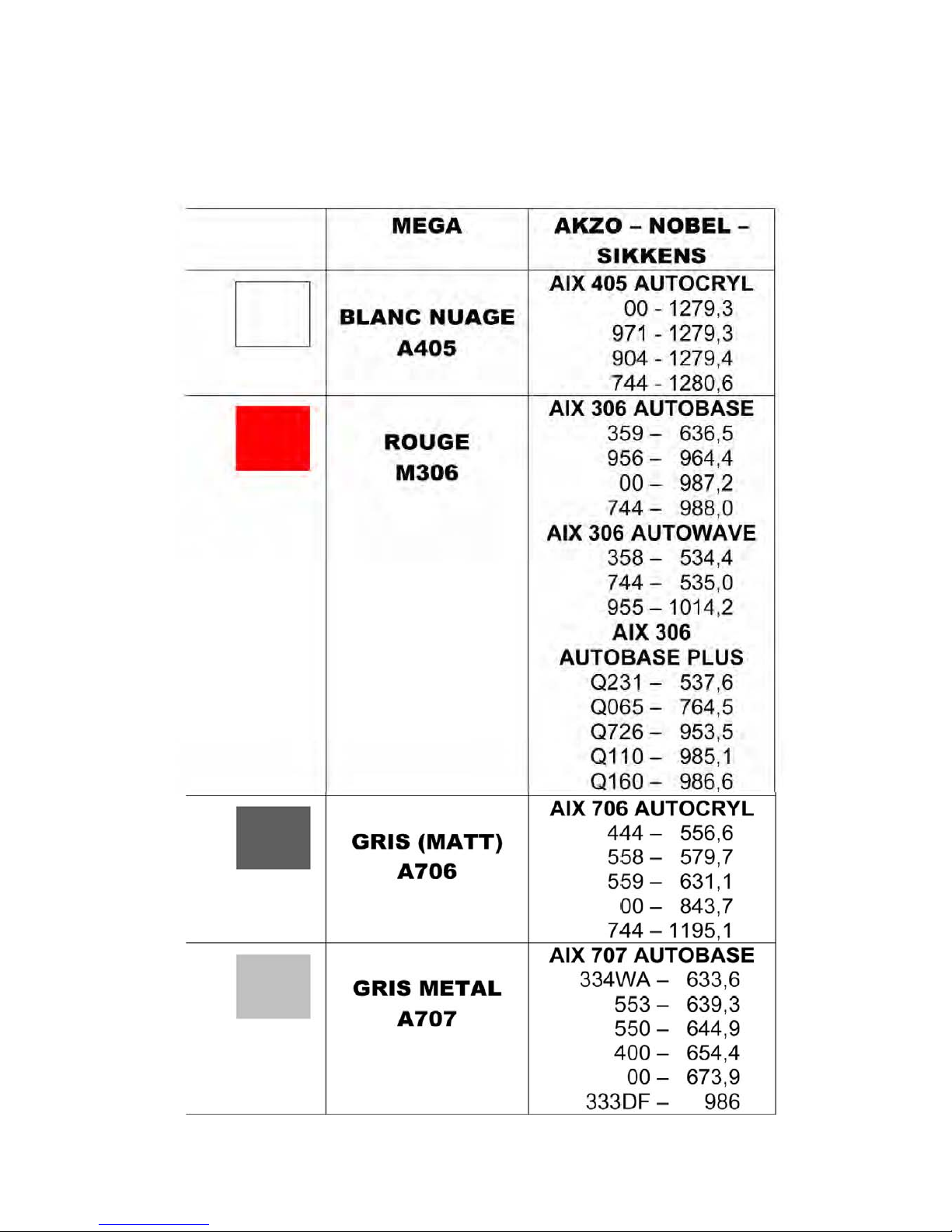
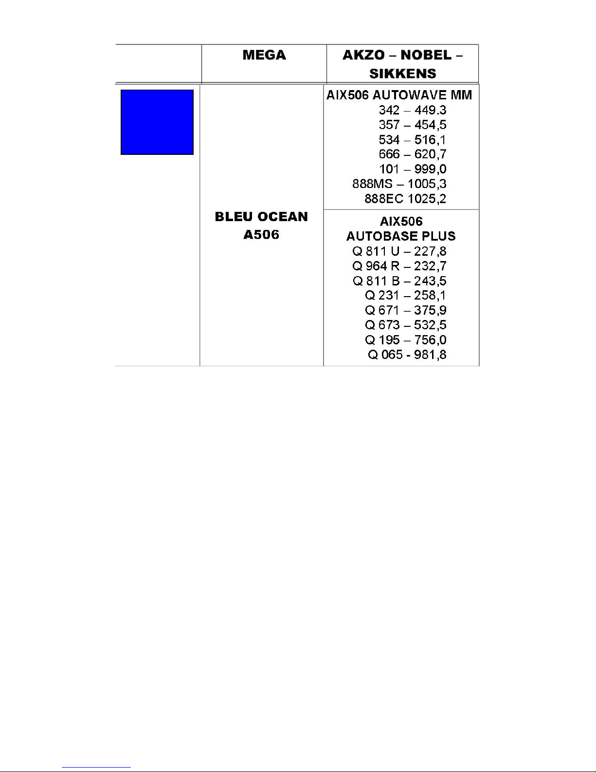
Group 9
Paint
Page 46
 Loading...