

Page 1
B ureau Veritas
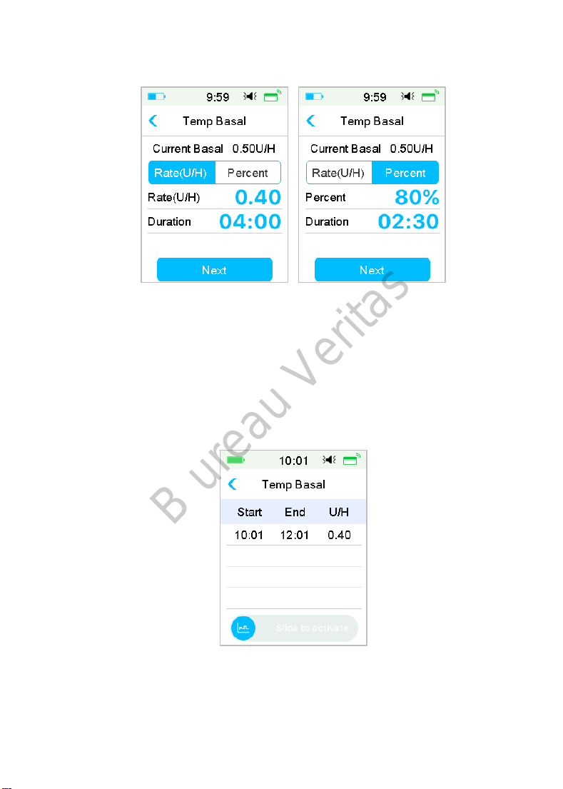
2. Select a temp basal type, temp rate or percent and duration, then
Tap Next to review the temporary basal rates set.
Note: If Percent is selected, you can set the temp basal rate, not exceeding the
Max Basal Rate, between 0 and 200% with an increment of 1%. If Rate (U/H) is
selected, you can set the temp basal between 0 and the Max Basal Rate with an
increment of 0.05 U/H.
Note: You can set the duration between 30 min and 24h with an increment of
30 min.
3. Make sure that the temp basal is correct in this Temp Basal Review, then
Slide to activate.
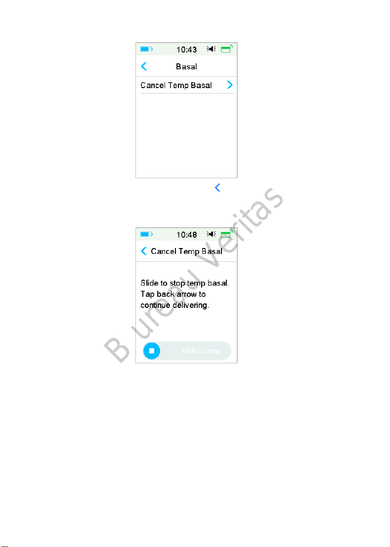
5.5.2 Cancel a Temp Basal
1. Go to the Cancel Temp Basal screen. Select Cancel Temp Basal.
135
Page 2
B ureau Veritas
Main Menu➔Basal➔Cancel Temp Basal
2. Slide to stop temp basal delivery, or tap to continue delivering.
Note: If you suspend insulin delivery while a temp basal rate is active, the temp
basal rate will be canceled.
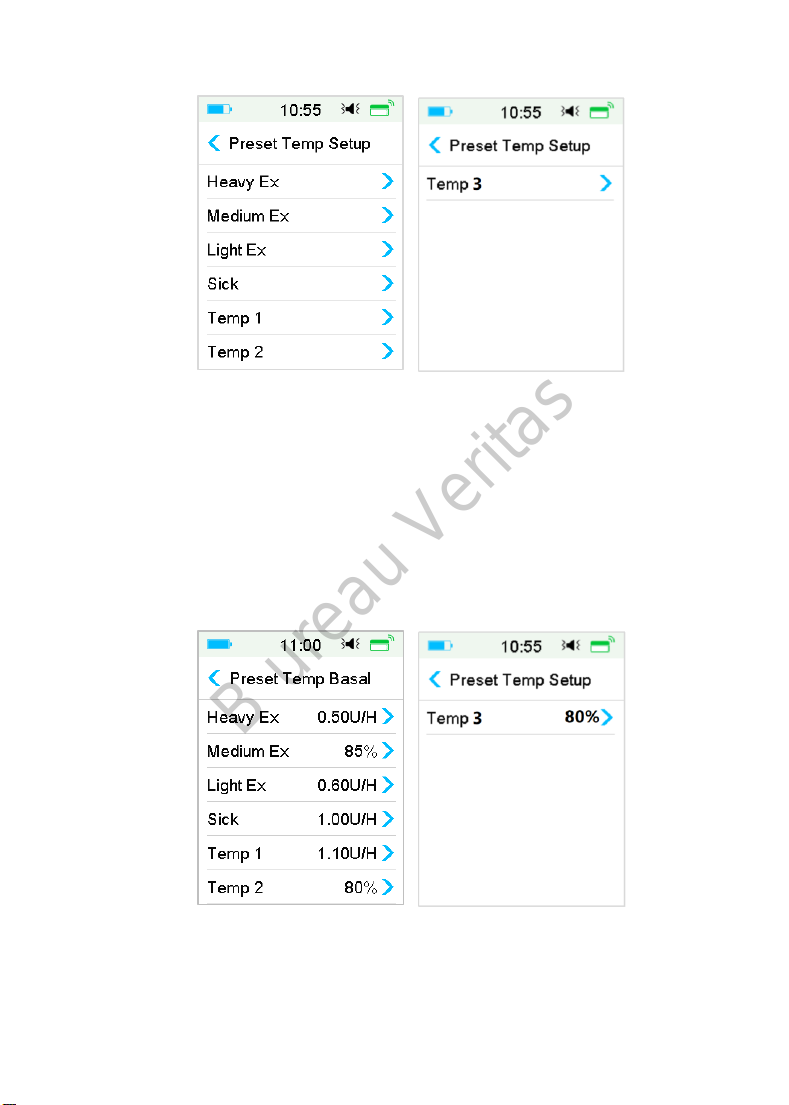
5.6 Preset Temp Basal
With the preset temp basal feature, you can program temp basal rates for
recurring short-term situations. You can set up to seven preset temp basal rates:
Heavy Ex, Medium Ex, Light Ex, Sick, Temp 1, and Temp 2 and Temp 3.
5.6.1 Preset Temp Basal Setup
1. Go to the Preset Temp Setup screen.
136
Page 3
B ureau Veritas
Main Menu➔Settings➔Insulin Pump➔Basal Setup➔Preset Temp Setup
2. Select a preset temp basal you want to edit. Choose the temp basal type
(rate or percent).
3. Set the duration and rate/percentage of the preset temp basal. Tap Save
to save settings.
5.6.2 Activate a Preset Temp Basal
You must set up a preset temp basal before you can activate it.
1. Go to the Preset Temp Basal screen.
Main Menu➔Basal➔Preset Temp Basal
The programmed preset temp basal types are displayed on this screen. If
you have not set up any preset temp basal rate, this screen shows No
Presets.
2. Select the preset temp basal you want to activate.
137
Page 4
B ureau Veritas
3. Confirm your preset temp basal settings.
4. Slide to activate.
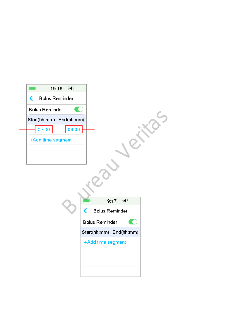
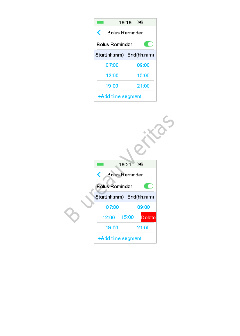
5.7 Reminder
5.7.1 Bolus Reminder
When you fail to deliver a Bolus at between time point A and time point B, you
will receive a Reminder at time point B.
1. Time Point A
1
You can add, delete, or review Reminders when the Bolus Reminder option is
turned on.
Go to the Bolus Reminder screen.
Main Menu➔Settings➔Reminders➔ Bolus Reminder
2
2. Time Point B
Add Reminder
Tap + Add time segment to add one Reminder, setting the start and end time.
138
Page 5
B ureau Veritas
Note:
(1) The end time should be at least 30 min later than the start time. You can
program up to four bolus Reminders.
(2) The Reminders will be saved automatically.
Delete Reminder
Slide from right to left on one segment, tap Delete to delete this segment.
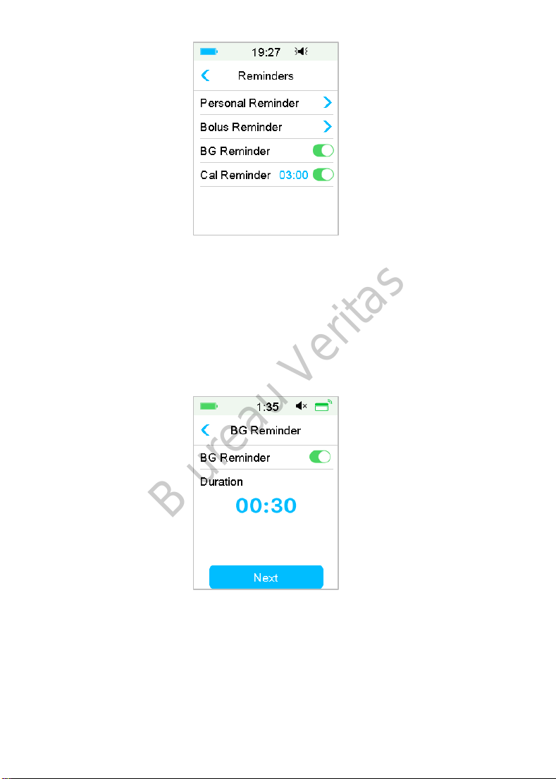
5.7.2 BG Reminder
After you deliver a bolus, you may want to check your BG. The BG Reminder is
an optional feature that reminds you to check your BG after a bolus.
Go to the BG Reminder Setup screen.
Main Menu ➔Settings➔Reminders➔BG Reminder
139
Page 6
B ureau Veritas
If you have BG Reminder turned on, the BG REMINDER DURATION screen
appears when you set Bolus.
It allows you to set the time before you are reminded to check your blood
glucose after a bolus.
The time ranges from 00:30 to 05:00 with an increment of 30 minutes. The
default time is 00:30.
You can also turn off the BG reminder after each bolus.
You can accept or modify the time before you are reminded.
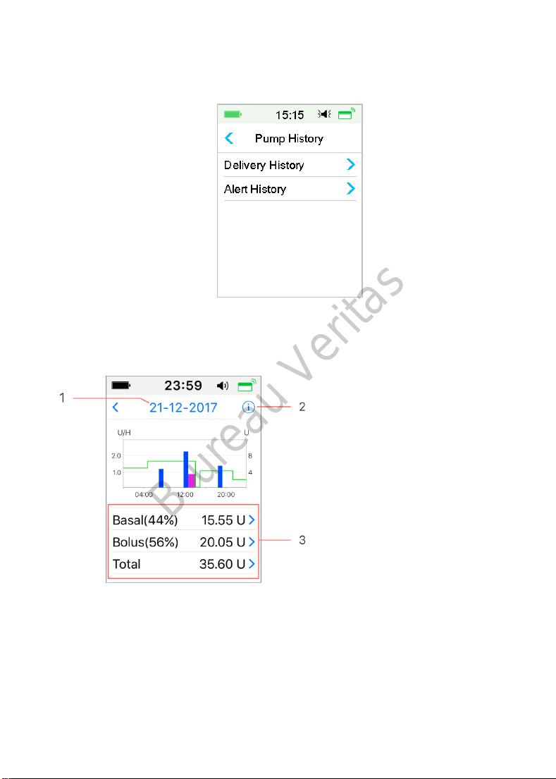
5.8 Pump History
5.8.1 Pump History
The Pump History displays the delivery history (bolus, basal and total daily
140
Page 7
B ureau Veritas
delivery history) and alert history (pump alerts and alarms).
Go to the Pump History screen.
Main Menu➔History➔Pump History
5.8.1.1 Delivery History
You can select one day to review its delivery graph. It displays the summary of
basal, bolus and total delivery for one day.
1. Tap the date to switch
between records of different
dates
2. Tap the info icon to
review legend meanings.
3. Tap the “Basal, Bolus,
Total “summary chart at the
bottom of Delivery History
screen to see details.
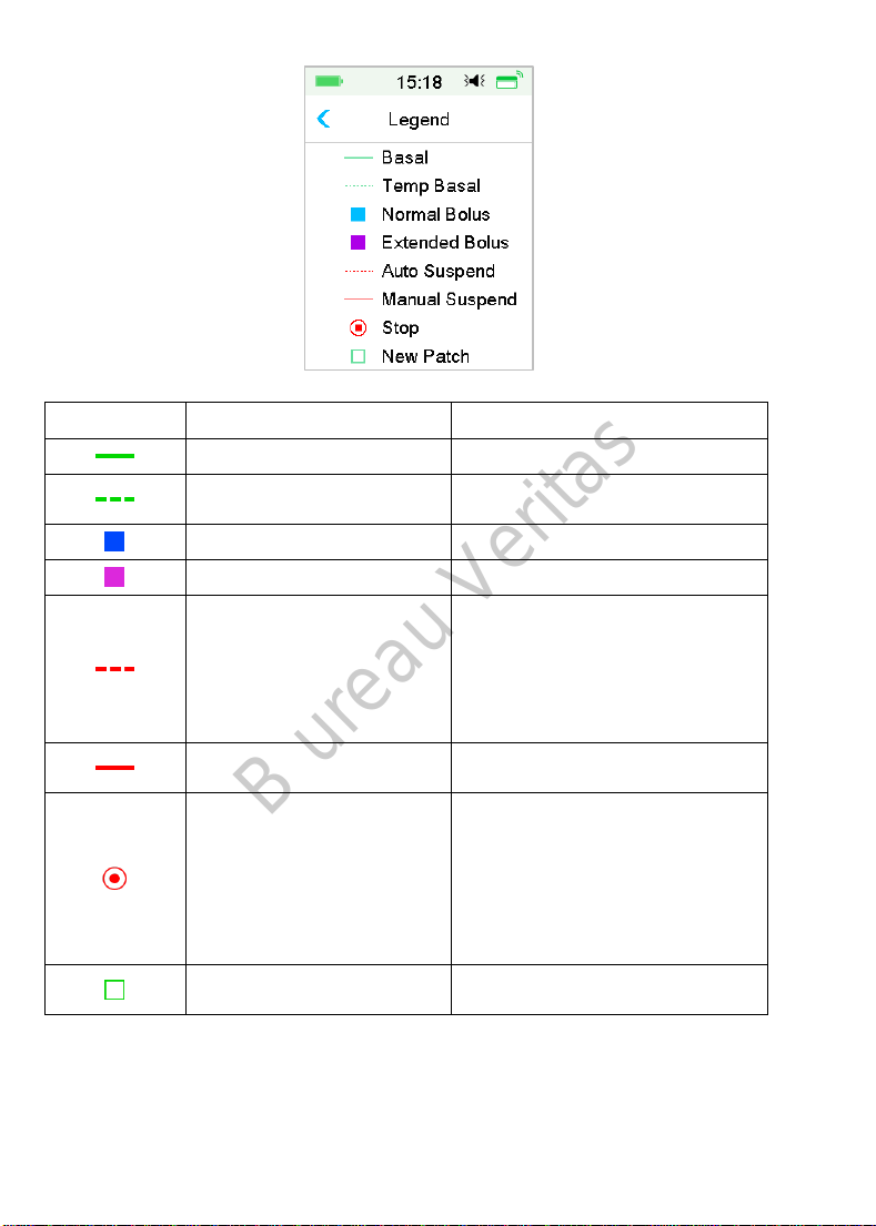
(1) The legend
141
Page 8
B ureau Veritas
Legend Abbreviation
Basal
Temp Basal
(2) Basal History
This screen displays most detailed Basal information.
Normal Bolus
Extended Bolus
Auto Suspend
Manual Suspend
Stop
New Patch
Significance
Basal Rate infusion curve
Temp Basal Rate infusion
curve
Normal Bolus delivery icon
Extended Bolus delivery icon
This tag appears when any of
the following alarms occurs:
AUTO OFF, PREDICTIVE LOW
SUSPEND, LOW SUSPEND,
EXCEEDS MAX TDD, EXCEEDS
MAX 1HR DELIVERY ALARM.
Manually suspend all insulin
delivery
Including deactivate patch,
discard patch, and alarms:
OCCLUSION DETECTED, PATCH
EXPIRED, PATCH ERROR,
PATCH BATT DEPLETED, PUMP
BASE ERROR, EMPTY
RESERVOIR.
When you activate a new
patch, this icon appears.
142
Page 9
B ureau Veritas
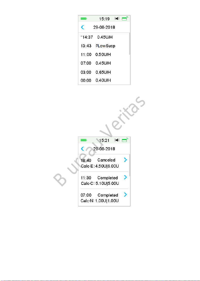
(3) Bolus history
The summary information includes:
⚫ The start time of this bolus;
⚫ Status of bolus: completed, canceled, delivering;
⚫ Bolus type;
⚫ Amount of bolus delivered |Amount of bolus programmed.
Bolus Type:
N: Normal Bolus
E: Extended Bolus
C: Combo Bolus
Normal: Normal Bolus by Manual Bolus
Extended: Extended Bolus by Manual Bolus
143
Page 10
B ureau Veritas
Combo: Combo Bolus by Manual Bolus
Calc-N: Normal Bolus by Bolus Calculator
Calc-E: Extended Bolus by Bolus Calculator
Calc-C: Combo Bolus by Bolus Calculator
Tap record line to view more detailed information. See Chapter “Advanced
Pump Features” for more information.
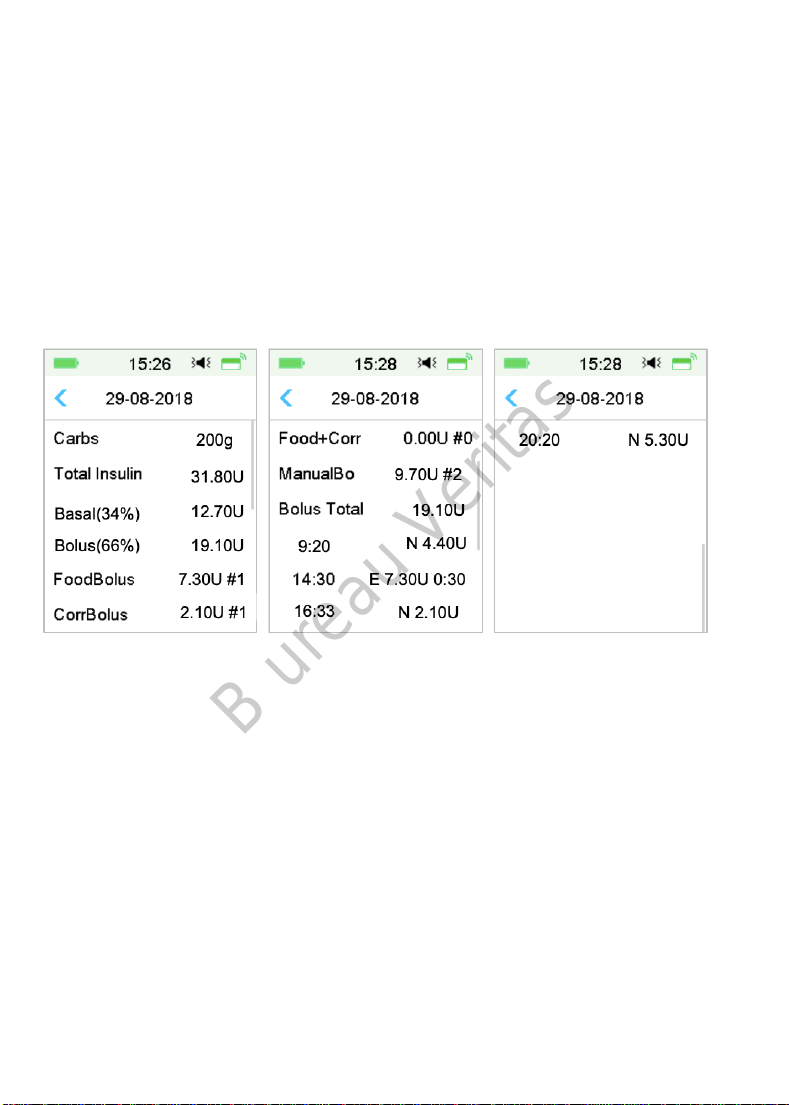
(4) Daily Totals
This screen displays most detailed Daily Totals information.
N represents Normal Bolus.
E represents Extended Bolus.
C represents Combo Bolus.
FoodBolus 7.30U #1 means that there is one food bolus doses in the
selected day with a total amount of 7.30U.
CorrBolus 2.10U #1 means that there is one correction bolus doses in the
selected day with a total amount of 2.10U.
Food+Corr 0.00U #0 means that there is no bolus dose that both covers
carbs and corrects glucose in the selected day.
ManualBo 9.70U #2 means that there are two manual bolus doses in the
selected day with a total amount of 9.70U.
144
Page 11
B ureau Veritas
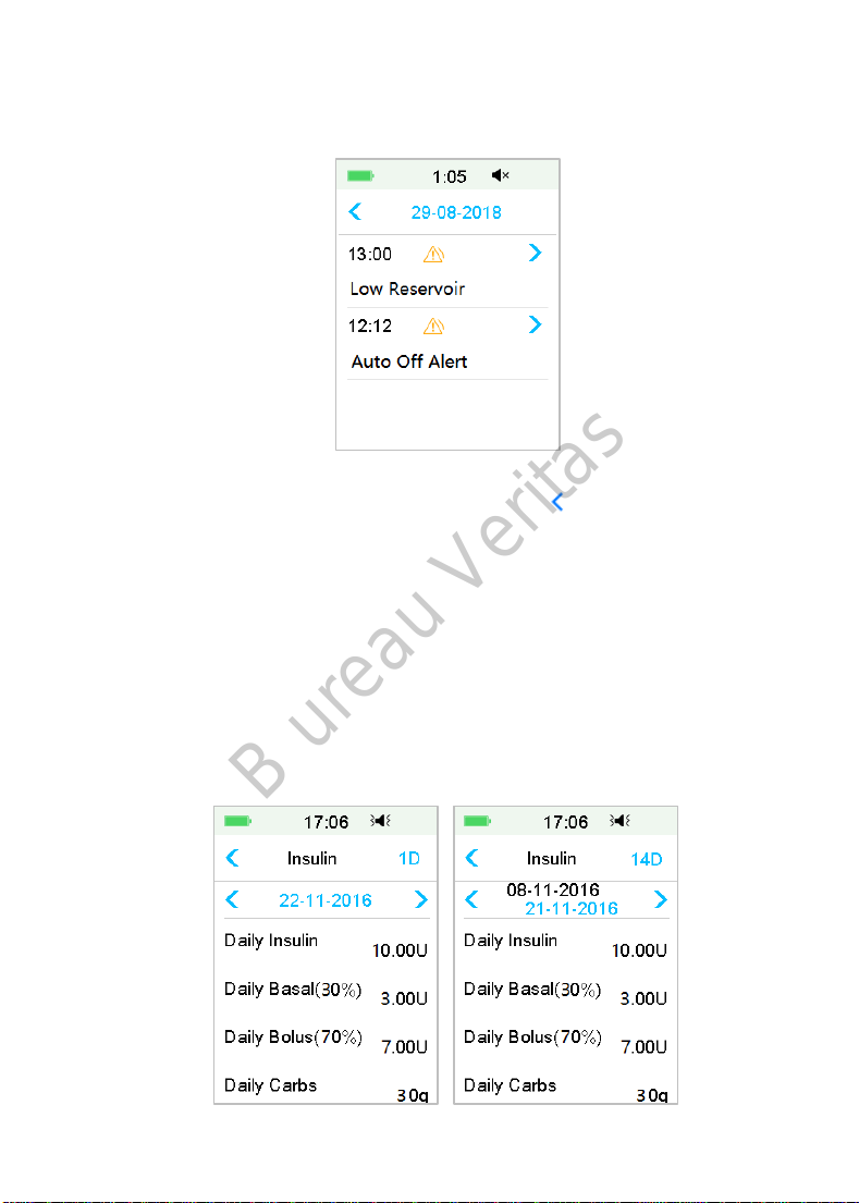
5.8.1.2 Alert History
Go to the pump Alert History screen.
Main Menu➔History➔Pump History➔Alert History
Tap the date to switch between records of different dates. Tap each Alert/Alarm
to view alert detail information. Tap to return to the previous menu.
See Section “Alert Icons” in Chapter “How to us the PDM” for more information
about how to address alarms and alerts and the meanings of different
alarm/alert icons.
5.8.2 Pump Summary History
5.8.2.1 Summary History: Insulin History
This screen displays the insulin delivery summary history.
Go to the Insulin History screen.
Main Menu➔History➔Summary History ➔Insulin History
145
Page 12
B ureau Veritas
Daily Insulin: Total daily dose of insulin delivered per day.
Daily Basal: Average daily dose and percentage of insulin delivered as Basal.
Daily Bolus: Average daily dose and percentage of insulin delivered as Bolus.
Daily Carbs: Average daily amount of carbs.
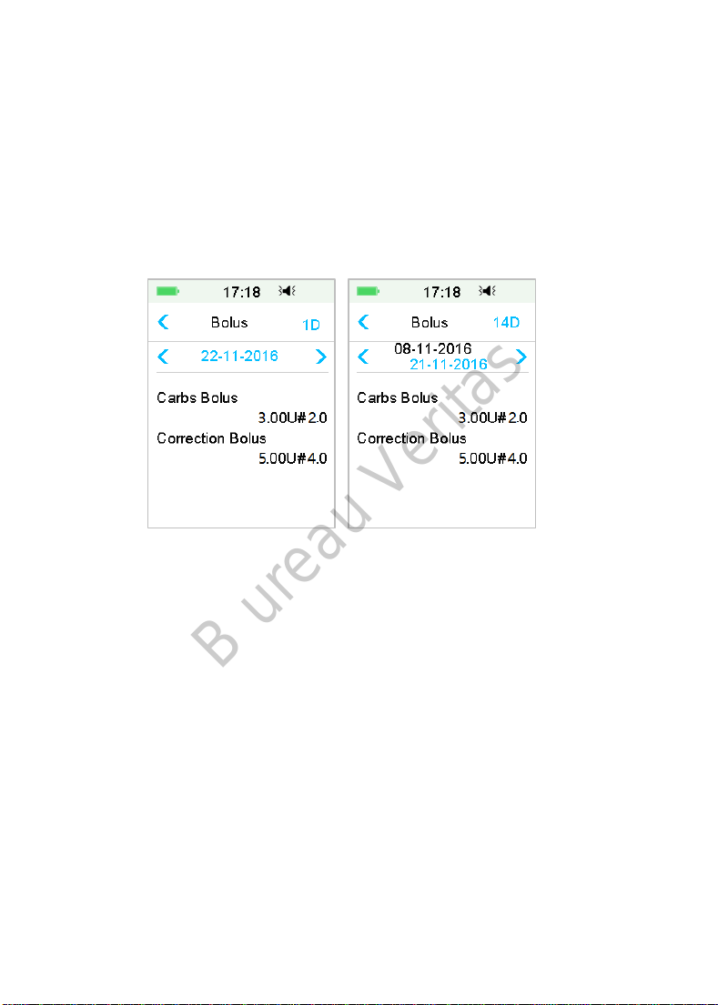
5.8.2.2 Summary History: Bolus History
This screen displays the Bolus summary history.
Main Menu➔History➔Summary History ➔Bolus History
Carbs Bolus Only: Average daily dose and the number of times of Food Bolus
only on the selected days.
BG Correction Only: Average daily dose and the number of times of BG
correction Bolus only on the selected days.
5.9 Troubleshooting Pump issues
Can I take a sauna with a Patch Pump on?
No.
Firstly, the operating temperature range for the Patch Pumps is +5°C ~ +40°C.
Secondly, if you take a sauna, insulin will be absorbed faster into your body, and
your blood glucose can fluctuate.
Can I dive with a Patch Pump on?
No.
146
Page 13

B ureau Veritas
Your Patch Pump is waterproof to a depth of 2.5 meters (8 feet) for up to 60
minutes (IPX8).
It means the maximum pressure the device can tolerate equals the pressure in
2.5m deep in STILL water instead of flowing water.
It is OK to take a shower or go swimming with the devices on, but if you go diving,
the water pressure may be too high for the devices.
I didn’t see an alert message, but it appeared in History.
If one of the following alerts happened, the PDM would beep/vibrate and
display a message first, and if you missed that alert, later when you checked the
PDM, the condition that triggered the alert had changed (for example, your
glucose level returned to the target range), then you wouldn't see any message
on the screen, you would only find it in History.
Alert Alert change
EXCEEDS MAX TDD After insulin delivery automatically starts
again, alert is switched to BASAL RESUMED.
EXCEEDS MAX 1HR DELIVERY After insulin delivery automatically starts
again, alert is switched to BASAL RESUMED.
If one of the following alerts happened, the PDM would beep/vibrate and
display a message first, and if you missed that alert, later when you checked the
PDM, the alert may have escalated to another alert/alarm, and you will ONLY
see the message of the escalated alert/alarm. The first alert will appear in
History.
Alert Alert escalation
LOW RESERVOIR EMPTY RESERVOIR
PATCH EXP ADVISORY PATCH EXP IN 1 HOUR, then PATCH EXPIRED
AUTO OFF ALERT AUTO OFF
Lights on the Patch Pump
Once you connect the pump base with a new Reservoir Patch, you will see the
indicator light flashing in the order of blue, green, yellow, and red. When you
are activating the new patch, you will see the green light flashing until the basal
pattern is activated.
A yellow (orange) light indicates an alert, while a red light indicates an alarm.
147
Page 14

B ureau Veritas
If the PDM is away from the Patch Pump, how will the basal rate be delivered?
The selected basal pattern is stored in the pump base, which means that even if
the PDM is away, the basal pattern will continue as planned.
Can I fill the patch with insulin when the patch is on body?
NO. NEVER DO THAT. Insulin can go directly into your body, which is very
dangerous.
No magnetic objects around when activating (priming)
When you are filling the Reservoir Patch, make sure that it is at least 30 cm (12
inches) from any magnetic objects, such as magnets, mobile phones, tablets,
other Reservoir Patches, TVs, refrigerators, and sound options. The Patch Pump
will detect the volume of insulin in the reservoir once it is filled, and if the Patch
Pump is in a magnetic field, the volume detected can be inaccurate.
148
Page 15

B ureau Veritas
149
Page 16

B ureau Veritas
150
Page 17
B ureau Veritas
6 How to use CGM system (Optional)
6.1 Glucose Alerts
Set your Low and High glucose alerts before using the sensor. See Section
“Glucose Alerts” in Chapter “How to use (P)LGS” for more information.
6.2 Change Sensor
Your Sensor gives glucose readings for up to fourteen days. When a Sensor
expires or fails, your Sensor session ends automatically, and PDM displays no
more glucose readings. You must remove the Sensor and disconnect the
Transmitter.
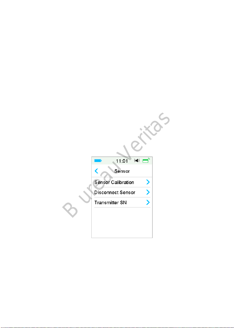
6.2.1 Disconnect Sensor from Your PDM
Go to Disconnect Sensor screen.
Main Menu➔Sensor➔Disconnect Sensor
Note: The Disconnect Sensor option is only available when a Sensor is currently
connected to the PDM.
151
Page 18
B ureau Veritas
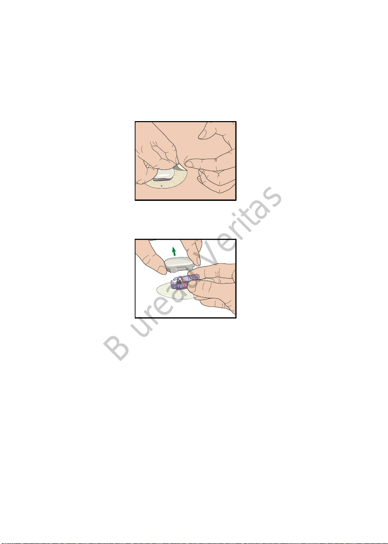
6.2.2 Remove the Current Sensor and Disconnect the
Transmitter
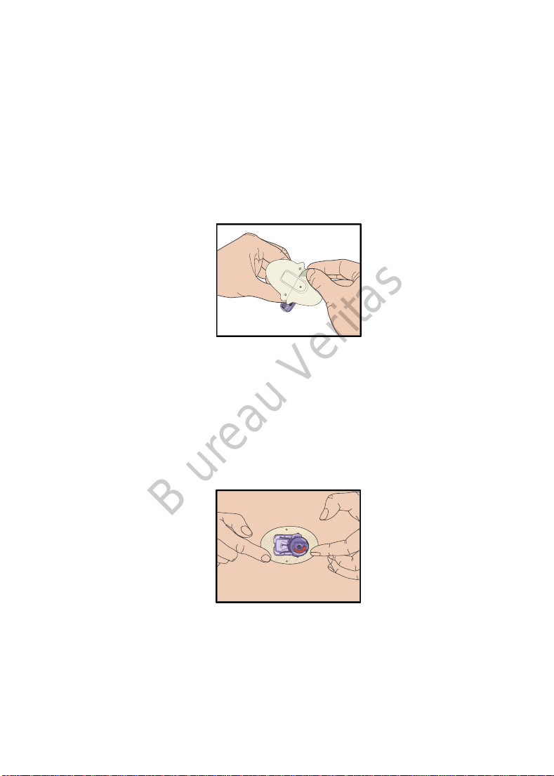
1. Gently peel the adhesive pad off your skin in one continuous movement
to remove the Sensor and Transmitter.
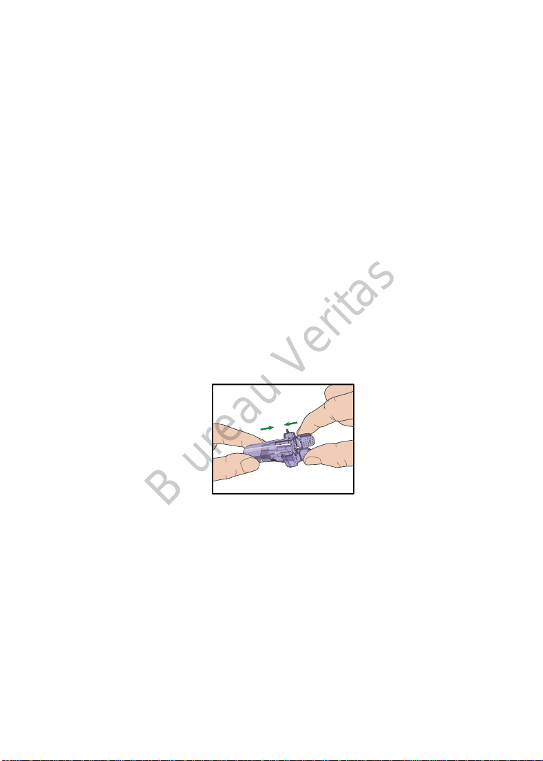
2. Pinch the ribbed release tabs on the sides of the Sensor support mount,
and gently pull the Transmitter away from the Sensor support mount.
3. Discard the Sensor support mount and reuse the Transmitter.
Note: Do Not discard your Transmitter. It is reusable and rechargeable.
Note: Make sure that you completely disconnect the Transmitter from the
Sensor when you do. Do NOT store the Transmitter connecting a Sensor or a
USB charging cable on which may kill the Transmitter battery.
6.2.3 Charge the Transmitter
The Transmitter is charged via a USB charging cable which is plugged into a USB
2.0/3.0 port or a power adapter with a rated voltage of DC 5V and a rated
current higher than DC 1000mA. The device with the USB port and the power
adapter must comply with EN 60950-1 or EN 60601-1.
152
Page 19
B ureau Veritas
The battery must be fully charged the first time you use the Transmitter, which
may take up to 2 hours. It is recommended to recharge the Transmitter after
each Sensor session. If a Transmitter is stored for two months, you must fully
charge the Transmitter battery to ensure it works properly.
The indicator light will flash when the Transmitter is being charged, and go off
when the Transmitter is fully charged.
Note: We recommend that your Transmitter is only charged by an intended and
qualified operator.
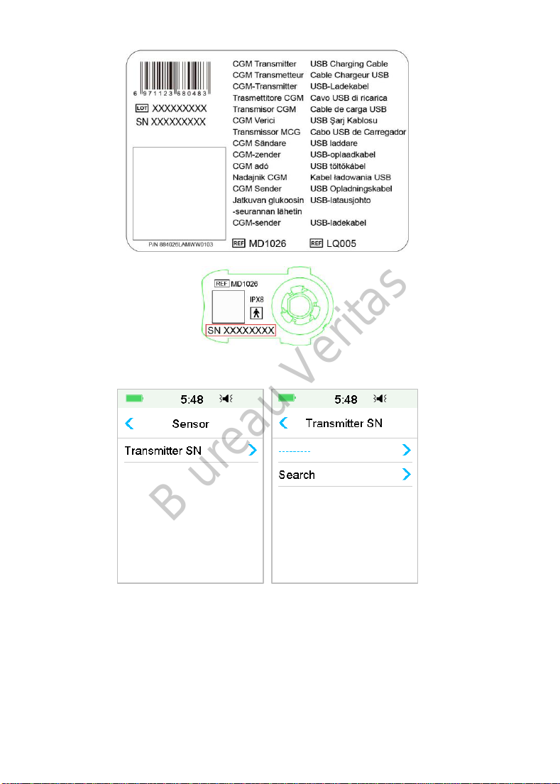
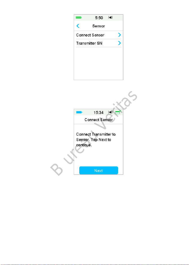
6.2.4 Add the Transmitter SN
Any time when you switch to a new Transmitter and/or a PDM you must add
the Transmitter SN.
Main Menu➔Sensor➔Transmitter SN
1. Tap Connect Sensor if you have set the Transmitter SN.
Note: Don’t forget to update the SN if you change to a new Transmitter.
Note: You can only change the Transmitter SN when there is no Sensor
connected.
You can find the Transmitter SN on the product box or on the back of the
Transmitter.
153
Page 20
B ureau Veritas
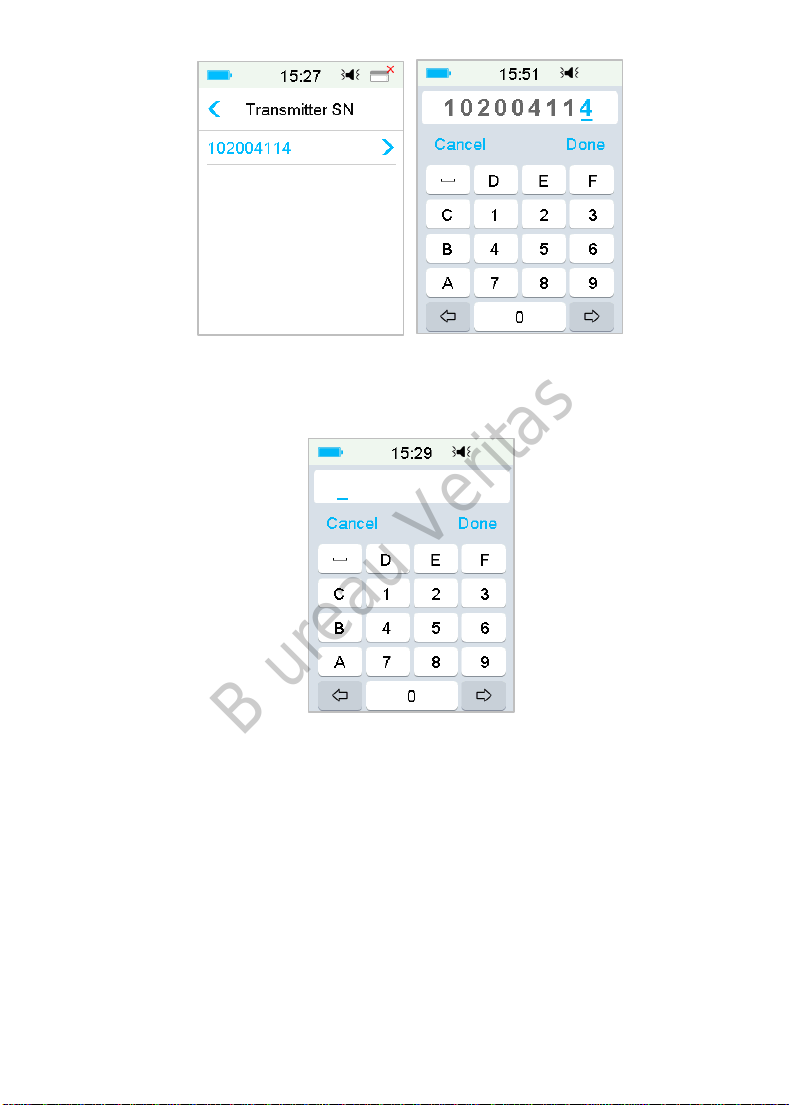
2. You can either enter SN manually or search for the SN if it is the first time you
enter the SN.
3. You can only enter SN manually if you want to update the SN.
154
Page 21
B ureau Veritas
Enter SN manually
Tap --------- or the existing Transmitter SN, you will see the following screen.
Then enter the SN to your PDM and press Done.
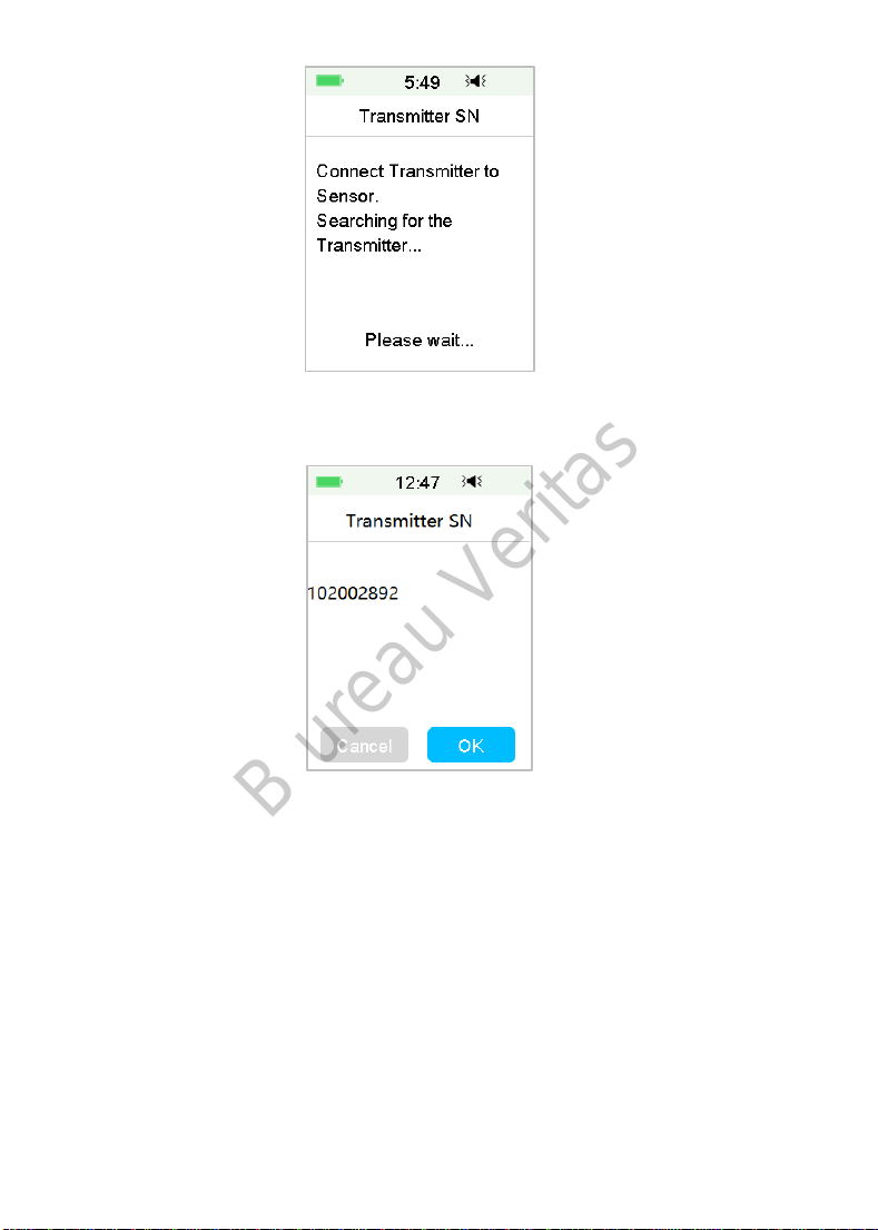
Search for the SN
If you select Search, make sure that your Transmitter is connected to a new
Sensor and move the PDM closer to your CGM before searching. See Section
“Insert a New Sensor” for more information.
If you tap Search in Sensor, you will see the following message when you search
for the SN.
155
Page 22
B ureau Veritas
If your PDM finds one Transmitter, the Transmitter SN appears on the screen.
Confirm it once it matches the SN printed on your Transmitter. If it is correct,
tap OK.
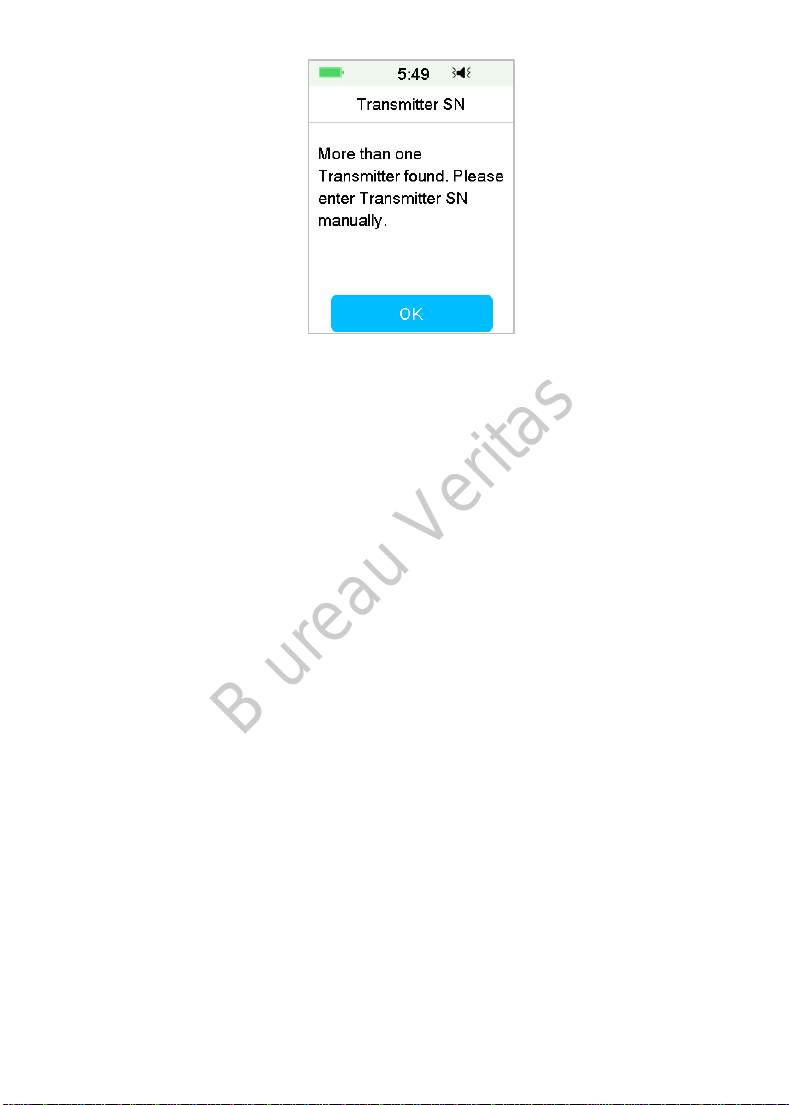
If your PDM finds multiple Transmitters, tap OK to go back to Sensor Menu,
then select “---------” to enter the SN manually.
156
Page 23
B ureau Veritas
If your PDM does not find a Transmitter, make sure that your Transmitter is
connected to a new Sensor, move the PDM closer to your CGM, and enter the
SN manually.
6.2.5 Insert a New Sensor
6.2.5.1 Select an Insertion Site
When choosing the location for the Sensor, consider the following:
That you can comfortably reach the Sensor.
That you apply the Sensor to a flat area of skin with adequate
subcutaneous fat.
That the area stays flat during normal daily activities without bending or
creasing.
When choosing the location for the Sensor, avoid the following:
Areas that are constrained by clothing, such as the belt line or waist.
Curved or rigid areas due to muscle or bone.
Areas that involve rigorous movement during exercise.
Areas of skin with scars, tattoos, or irritation.
5.0 cm (2 inches) around the navel.
Areas with excess hair.
Within 7.5 cm (3 inches) of an insulin pump infusion site or manual
injection site.
Shown here are the best body areas (shaded) for Sensor insertion.
157
Page 24

B ureau Veritas
Front Back Front Back
If you choose an insertion site on your abdomen (buttock for children), apply
the Sensor horizontally. If you choose an insertion site on your upper arm, apply
the Sensor vertically.
Have a rotation schedule for choosing a new site. Using the same site too often
might not allow the skin to heal and can possibly cause scarring or skin irritation.
6.2.5.2 Prepare the Insertion Site
1. Wash your hands thoroughly with soap and water and wait for them dry
up.
2. Wipe the selected insertion area with rubbing alcohol and wait for the area
to dry up. This may help prevent infection. Do NOT insert the Sensor until
the cleaned area is dry. This will make the Sensor adhesive stay on the skin
more firmly.
Warning: If the Sensor dislodges because the Sensor support adhesive fails to
adhere to the skin, you may get false or no readings. Improper site selection and
improper site preparation may result in poor adhesion.
6.2.5.3 Unpack the Glucose Sensor
Open the Sensor package by peeling off the paper on the back of the package.
Pay attention to the following:
Warning: Do NOT use a Sensor if its sterile package has been damaged or
opened, or the Sensor has expired, or the Sensor is damaged in any way.
Note: Wash your hands with soap and water and let them dry before opening
the Sensor package and handling the Sensor. After opening the package, avoid
touching any Sensor surface that will be in contact with the body, i.e., adhesive
158
Page 25
B ureau Veritas
surface. You may contaminate the insertion site and suffer an infection if you
have unclean hands while inserting the Sensor.
6.2.5.4 Remove the Protective Liner from the Sensor Support
Mount
Bend the two-piece protective liner slightly on the edge so you can see the seam
between the two pieces. Hold the inserter part of the Sensor, and try not to
touch the adhesive surface. Remove the liners from the Sensor support mount
one after another.
6.2.5.5 Locate the Sensor Support Mount
If you are inserting the Sensor on your abdomen or lower back, place the Sensor
horizontally on your skin.
If you are inserting the Sensor on your upper arm or thigh, place the Sensor
vertically on your skin.
Move your fingers around the adhesive pad to secure it to your skin.
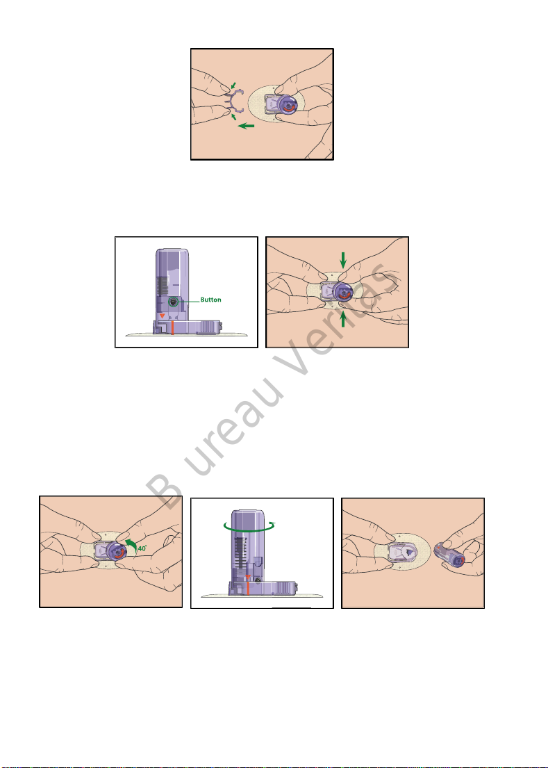
6.2.5.6 Remove the Safety Lock
Hold the Glucose Sensor with one hand. Firmly squeeze the two release tabs of
the safety lock with your thumb and index finger of the other hand, as you lift
the safety lock away from the inserter. Keep the safety lock, you will need it
later.
159
Page 26
B ureau Veritas
6.2.5.7 Insert the Sensor
Hold the inserter as shown below and press the two buttons at the same time.
You might feel a slight pinch as the Sensor is placed just under your skin.
6.2.5.8 Remove the Inserter
Pinch and hold the ribbed release tabs on the sides of the Sensor support mount
with one hand, twist the inserter about 40° in the direction (anticlockwise)
shown with the other hand, until the orange triangle marked on the inserter
lines up with the orange line on the Sensor support mount, and then lift the
inserter vertically away from the mount. Only the Sensor support mount will be
left on your body.
160
Page 27
B ureau Veritas
6.2.5.9 Check the Sensor Support Mount
Confirm that the Sensor support mount remains tightly adhered to your skin
by sliding your finger along the edges of the adhesive pad and examine for any
gaps in adhesion.
Warning: If bleeding occurs at the insertion site, do not attach the Transmitter
to the Sensor. Apply steady pressure using a sterile gauze or clean cloth for up
to 3 minutes. If bleeding stops, attach the Transmitter to the Sensor. If bleeding
continues, remove the Sensor, treat the site as necessary, and insert a new
Sensor at a different site.
Warning: Check the insertion site frequently for infection or inflammation
redness, swelling or pain. Remove the Sensor and seek professional medical
help if one of these conditions occurs.
6.2.5.10 Discard the Sensor Inserter Safely
Attach the safety lock on the inserter to cover its opening and conceal the
needle inside. Follow local waste disposal regulations when discarding the
inserter. We recommend discarding the Sensor inserter into a sharps container
or a puncture-proof container with a tight lid.
6.2.6 Attach Your Transmitter
Note: If you are changing Sensor, make sure that your Transmitter was
disconnected from the old Sensor at least one minute before being connected
to the new Sensor.
Before attaching the Transmitter to the Sensor, you must have the Transmitter
battery fully charged and the PDM set up.
Snap the Transmitter into the Sensor support mount until the two flexible arms
fit into the notches on the Transmitter. The indicator light will flash green after
161
Page 28
B ureau Veritas
successful connection, three times after properly connected and another six
times after successful system check.
Note: Make sure that you hear a click when you snap the Transmitter in place.
If it is not fully snapped in, electrical connection and waterproof can be
compromised, which can lead to inaccurate Sensor glucose readings.
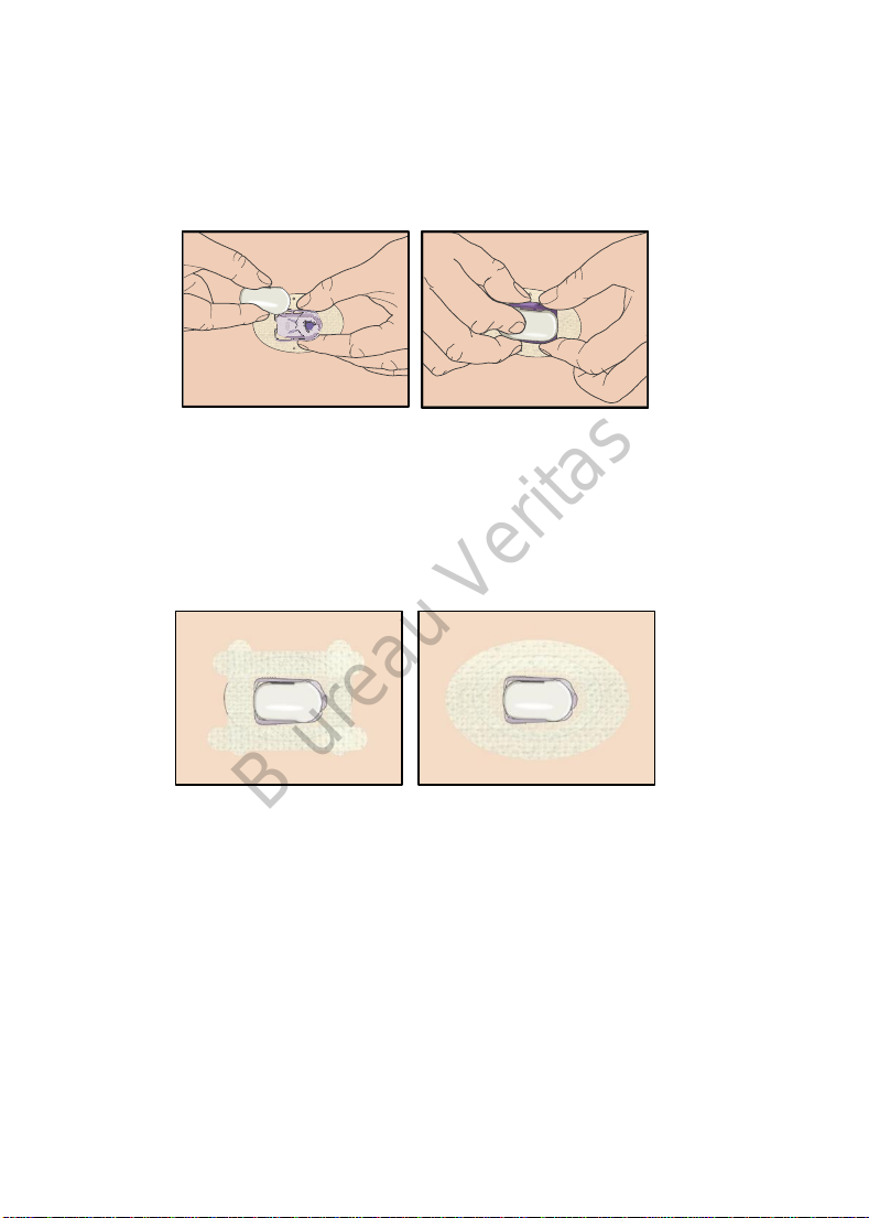
Tape the Sensor Support Mount (Optional)
The Sensor support mount should stay on your skin using its own adhesive. But,
if you find that the Sensor support mount is not adhering well during daily
activities, you can use medical tape for extra support. Only tape over the white
adhesive pad on all sides for even support. Do NOT tape over the Transmitter or
any of the plastic parts on the Sensor support mount.
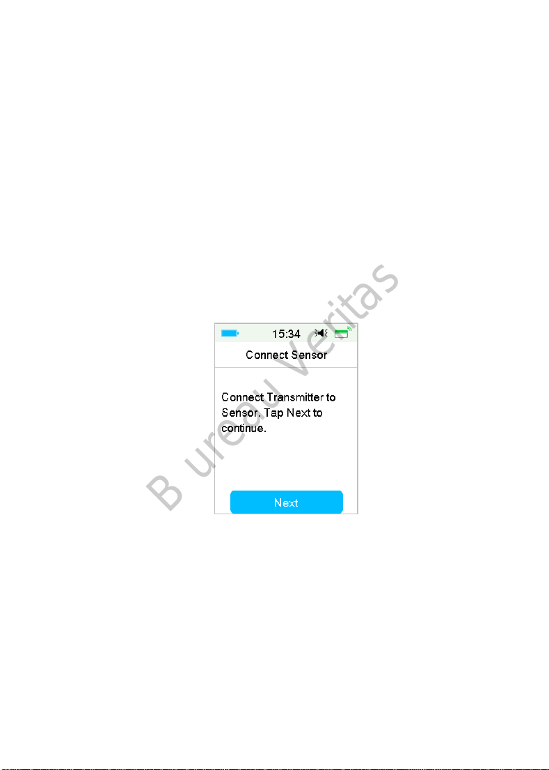
6.2.7 Connect Sensor to Your PDM
1. Go to Connect Sensor screen.
Main Menu➔Sensor➔Connect Sensor
162
Page 29
B ureau Veritas
Note: The Connect Sensor option is only available when no Sensor is currently
connected to the PDM.
2. Make sure that your Transmitter is connected to a Sensor and that your
Transmitter SN is found or entered, and then continue by tapping Next.
3. If the sensor is calibration-free, enter the sensor code on the sensor label
which is unique for each sensor. Once the sensor code is entered
successfully, the calibrations aren’t required.
Or, skip the sensor code input step and go to Connection screen. The
sensor need to be calibrated twice (once every 12 hours) on the first day
and then once every 24 hours since the second day.
4. When finished, the following screen appears.
163
Page 30
B ureau Veritas
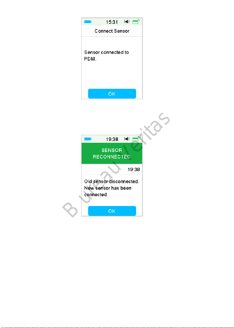
Note:
If you want to remove a Sensor before its expiration, disconnect it from your
PDM first before you connect a new Sensor. When you connect a new Sensor
directly, a “SENSOR RECONNECTED” message will appear on your PDM.
6.3 Calibrate Your Sensor
Each time the PDM prompts you with the message “METER BG NOW” or
“SENSOR CAL REMINDER”, you must enter a BG measurement to calibrate your
Sensor.
Go to the Sensor Calibration screen.
Main Menu➔Sensor➔Sensor Calibration
164
Page 31

B ureau Veritas
Note: If your sensor is not a calibration-free sensor, or you skip the sensor
code input step, you must calibrate your sensor at least twice (once every 12
hours) on the first day and then once every 24 hours since the second day. If
you have entered sensor code successfully, the system won’t require
calibration. But you can calibrate the sensor if you want.
Note: Calibration is unavailable under the following circumstances:
Sensor disconnected from the PDM
Sensor warm-up
Within 15 min after the alert SENSOR CAL ERROR
Poor RF communication between the Transmitter and the PDM
No Readings
6.3.1 Enter Your Meter BG
Here you can enter your present blood glucose measured by a finger prick
blood glucose meter.
1. Go to the Enter BG screen.
Main Menu➔Sensor➔Sensor Calibration
165
Page 32

B ureau Veritas
Note: Please enter the exact blood glucose value of a carefully performed
fingerstick displayed on your blood glucose meter within five minutes.
2. Tap Done to confirm your fingerstick, then tap Yes button to start
calibration.
3. When finished, the following screen appears.
166
Page 33

B ureau Veritas
6.3.2 Set Calibration Repeat
Go to the Cal Repeat screen.
Main Menu➔Settings➔CGM System➔Cal Repeat
After you receive and clear a “METER BG NOW” alert, PDM will repeat the
alert until you enter a new blood glucose measurement.
You can turn Cal Repeat on/off. If Cal Repeat is on, you can set the repeat time
of “METER BG NOW” alert from 5 min to 1h with an increment of 5 min.
6.3.3 Calibration Reminder
Calibration reminder enables you to get reminded a certain time before the
due time of next calibration.
1. Go to the Cal Reminder screen.
167
Page 34

B ureau Veritas
Main Menu➔Settings➔Reminders ➔Cal Reminder
2. You can turn Cal Reminder on/off.
Note: If Cal Reminder is on, you can set the time between 5 min and 6 h with
an increment of 5 min.
6.4 CGM System settings
Go to the CGM System screen.
Main Menu➔Settings➔CGM System
6.4.1 CGM Feature on/off
The CGM feature must be turned on to receive Sensor data.
1. Select CGM System in the Settings menu.
Main Menu➔Settings➔CGM System
168
Page 35

B ureau Veritas
2. You can turn on or off the CGM feature.
3. After you turn on the CGM System, the Transmitter SN menu appears.
6.4.2 Set the Transmitter SN
Tap Settings on the Main Menu to enter the Settings screen. Tap CGM System
to enter the CGM settings screen. Turn the CGM System feature on.
Tap Transmitter SN to add this Transmitter to your PDM. You can use your
PDM to search for your Transmitter (only for the first time), or you can enter
the SN printed on your Transmitter manually.
You can also enter your new Transmitter SN in CGM System menu. See “Add the
Transmitter SN” for more information.
169
Page 36

B ureau Veritas
6.4.3 Graph Range
You can set the time range of sensor graph in horizontal screen as 3, 6, 12, 24
hours. The default range is 12 hours.
6.4.4 Cal Repeat
See Section “Calibrate Your Sensor” in this chapter for more information.
6.4.5 Alert Silence
Go to the Alert Silence screen.
Main Menu➔Settings➔CGM System➔Alert Silence
Warning: Muting the alarms is not recommended when you are unable to
interact with your PDM (for instance, when you are asleep).
170
Page 37

B ureau Veritas
Interacting with your PDM includes activities such as pressing the power
button and checking the screen.
With the Alert Silence feature you can keep glucose alerts silent for a specified
time of 30 minutes to 24 hours.
There are five Alert Silence options:
Off— This means all glucose alerts are turned on: the PDM will beep or
vibrate if any Sensor alert occurs.
Low — The PDM will not beep or vibrate if a low alert (LOW GLUCOSE,
RAPID FALL or LOW PREDICTED) occurs during the specified time.
High — The PDM will not beep or vibrate if a high alert (HIGH GLUCOSE,
RAPID RISE or HIGH PREDICTED) occurs during the specified time.
High and Low — The PDM will not beep or vibrate if a high/low alert
(HIGH/LOW GLUCOSE, RAPID RISE/FALL, HIGH/LOW PREDICTED) occurs
during the specified time.
All — The PDM will not beep or vibrate if “LOST SENSOR”, “SENSOR CAL
REMINDER”, “METER BG NOW”, “SENSOR EXP IN 6 HOURS”, “SENSOR EXP
IN 2 HOURS”, “SENSOR EXP IN 30 MINS”, “SENSOR EXPIRED”, or any of
the high/low alert occurs during the specified time.
See “Status Bar Icons” and Chapter “Safety System and Alarms/Alerts” for
more information.
6.4.6 Sensor Expired
Go to the Sensor Expired screen.
Main Menu➔Settings➔CGM System➔Sensor Expired
171
Page 38

B ureau Veritas
For MD1026, the expiration date is fixed as 14 days.
In both settings, “SENSOR EXP IN 6 HOURS” alert, “SENSOR EXP IN 2 HOURS”
alert, “SENSOR EXP IN 30 MIN” and “SENSOR EXPIRED” alert will respectively
appear.
6.5 Sensor History
6.5.1 Sensor History
Your PDM stores detailed Sensor history to help you keep track of your glucose
readings and Sensor conditions.
Go to the Sensor History screen.
Main Menu➔History➔Sensor History
6.5.1.1 Data History
1. Select Data History in the Sensor History screen.
The Data History screen shows all of the Sensor sessions that have recently
occurred. Each line shows the Sensor session start date and duration
(day/hour/minute). For example, the record 28-08-2018 5/21/8 means the
Sensor was started on 28-08-2018 and has been used for 5 days 21 hours and 8
minutes.
172
Page 39

B ureau Veritas
2. Select a Sensor session and you will see the last day’s Sensor history data.
The Y-axis of the Sensor graph is featured by four values: 5, 10, 15, 20 mmol/L
(90, 180, 270, 360 mg/dL). The X-axis of the Sensor graph presents a period of
24 hours.
The Sensor graph can be switched to a landscape screen display. Long tap the
Sensor graph for 1 second and the display will turn horizontal.
Note:
⚫ Tap the Sensor graph and move the cursor to spot the glucose values. Use
the left and right arrow button to do fine adjustment for choosing the time.
The time interval between two values is 2 minutes.
⚫ The time a new Sensor is applied will be marked with a green square tag
“ ”. Readings during warm-up phase will not be displayed but marked as
“warm-up”.
173
Page 40

B ureau Veritas
⚫ Glucose value or special status will always be shown in the area below,
between the left and right arrow button. Special status includes: calibration
error (ERR), no readings (???), warm-up phase (Warm-up), Sensor glucose
is above 22.2 mmol/L or 400mg/dL (HIGH) and Sensor glucose is below 2.2
mmol/L or 40mg/dL (LOW).
⚫ After the warm-up phase, the values before the first calibration are marked
as “BG“.
⚫ When the Sensor calibration expires, the reading values will be underlined.
⚫ Calibration will be marked with a red dot “ ”.
⚫ In the landscape screen display, tap the Home Key to return to the Home
Screen.
⚫ In the following situations, you cannot enter landscape screen by long-
pressing the graph
⚫ when no Sensor is connected.
⚫ when the data is being recovered after reconnection.
3. Tap the date and you will see a list of dates within that session.
4. Select a date and you will see the 24-hour Sensor trend graph of that day.
6.5.1.2 Calibration History
Select Calibration History in the Sensor History screen. The Calibration
History screen displays the calibration history.
174
Page 41

B ureau Veritas
6.5.1.3 Alert History
Select Alert History in the Sensor History screen. The Alert History screen
shows you all of the Sensor alerts that have recently occurred.
Select an alert record to view the details. Tap to return to the previous
menu.
See Section “Alert Icons” and Chapter “Safety System and Alarms/Alerts” for
more information about how to address the alarms and alerts.
6.5.2 Summary History: Sensor History
This screen displays the SG readings summary history.
Go to Sensor History screen.
Main Menu➔History➔Summary History➔Sensor History
175
Page 42

B ureau Veritas
Average SG: Average SG readings of the selected days.
Time in target range: The percentage of the duration in which SG reading is in
the target range (3.9 - 10.0 mmol/L or 70 - 180 mg/dL).
Time above range: The percentage of the duration in which SG reading is above
the target range (10.0 mmol/L or 180 mg/dL).
Time below range: The percentage of the duration in which SG reading is below
the target range (3.9 mmol/L or 70 mg/dL).
6.6 Troubleshooting CGM issues
Can I take a sauna with the CGM System on?
No.
Firstly, the operating temperature range for the Transmitter is +5°C ~ +40°C.
Secondly, if you take a sauna, your blood glucose can fluctuate.
Can I dive with a Sensor on?
No.
Your Sensor (including the installed Transmitter) is waterproof to a depth of 2.5
meters (8 feet) for up to 60 minutes (IPX8).
It means the maximum pressure the device can tolerate equals the pressure in
2.5m deep in STILL water instead of flowing water.
It is OK to take a shower or go swimming with the devices on, but if you go diving,
the water pressure may be too high for the devices.
176
Page 43

B ureau Veritas
I didn’t see an alert message, but it appeared in History.
If one of the following alerts happened, the PDM would beep/vibrate and
display a message first, and if you missed that alert, later when you checked the
PDM, the condition that triggered the alert had changed (for example, your
glucose level returned to the target range), then you wouldn't see any message
on the screen, you would only find it in History.
1. LOW GLUCOSE
2. HIGH GLUCOSE
3. LOW PREDICTED
4. HIGH PREDICTED
5. RAPID RISE
6. RAPID FALL
7. ALERT SILENCE
8. SENSOR ERROR
9. BELOW 3.1 mmol/L (56 mg/dL)
10. LOST SENSOR
If the following alert happened, the PDM would beep/vibrate and display a
message first, and if you missed that alert, later when you checked the PDM,
the alert may have escalated to another alert/alarm, and you will ONLY see the
message of the escalated alert/alarm. The first alert will appear in History.
Alert Alert Escalation
SENSOR EXP IN 6 HOURS
SENSOR EXP IN 2 HOURS, then SENSOR
EXP IN 30 MIN, at last SENSOR EXPIRED
Charging the Transmitter
We recommend that you charge the Transmitter after each Sensor session, or
make sure that at least 1 minute has passed before you attach the Transmitter
to a new Sensor.
Green lights after installing the Transmitter
After you install the Transmitter, the green light on the Transmitter will flash 3
times immediately indicating that the Transmitter is properly connected with
the Sensor, and flash another 6 times within one minute indicating that the
system check has completed.
177
Page 44

B ureau Veritas
Some Sensor readings missing on the Sensor Trend Screen
If the PDM is too far away from the Transmitter, or the Bluetooth
communication between the Transmitter and the PDM is temporarily
interrupted, some Sensor readings might be missing in the Sensor Trend Graph
screen.
Solution: Move the PDM close to the Transmitter, and wait for a while. The data
will be recovered automatically.
What to do when a “Lost Sensor” alert happens
Move the PDM closer. If the PDM cannot connect with the Transmitter in 10
minutes, keep the Sensor in, disconnect the Sensor from the PDM menu, and
connect again.
178
Page 45

B ureau Veritas
179
Page 46

B ureau Veritas
180
Page 47

B ureau Veritas
7 How to use (P)LGS (Optional)
7.1 (P)LGS settings
The Glucose Alerts and Low Glucose Suspend/Predictive Low Glucose Suspend
(Low Suspend/ Pre Low Suspend) functions are included under the EasyLoop
Menu. The (Pre) Low Suspend function is available when CGM and Insulin Pump
systems are both online. The glucose limits for alerts of Low Suspend and Pre
Low Suspend are the same.
Tap EasyLoop on the Home Menu Screen to enter the EasyLoop screen.
7.1.1 Glucose Alerts
When the glucose alerts feature is turned on, the system can send you glucose
alerts including High/Low Glucose, High/Low Predicted and Rate Alerts.
Main Menu➔EasyLoop➔Glucose Alerts
181
Page 48

B ureau Veritas
1. You can turn on or off the Glucose Alerts.
2. Tap to save the settings.
7.1.1.1 High/Low Limits
You need to set the high and low Glucose Limits recommended by your
healthcare provider after you turn the glucose alerts On. Your recommended
glucose limits may vary throughout the day, you can set up to eight pairs for
different time periods.
Go to the Glucose Limits screen.
Main menu➔EasyLoop➔Glucose Alerts➔Glucose Limits
182
Page 49

B ureau Veritas
1. Add segments
The starting time of the first segment is fixed to be 00:00 or 12:00A.
Add time segments by choosing from 00:30-23:30 or 12:30A-11:30P, with an
increment of 00:30.
You will be reminded if the time segment to be set already exists. When the
time segments are successfully set, they will be listed chronologically.
If you only set one segment, the glucose limits of this segment will be applied
for 24 hours.
You can set up to 8 segments with the Low and High limits for each during real-
time monitoring.
Note:
⚫ In the time segments, only the segment starting from 0:00 cannot be
deleted. You can always edit the input in each segment. The Low Limit
183
Page 50

B ureau Veritas
rage is 2.8-5.0mmol/L (50-90 mg/dL), the High Limit range is 5.5-
22.2mmol/L (100-400 mg/dL), both with an increment of 0.1mmol/L
(1mg/dL). The High Limit value is always larger than the Low Limit value.
⚫ In the first segment, the default Low Limit is 4.4mmol/L, the default
High Limit is 13.3mmol/L.
2. Delete Segments
Slide from right to left on one segment, tap Delete to delete this segment.
3. Tap to save the settings.
7.1.1.2 Predictive Alerts
The predictive alerts calculate when you are going to reach your Low or High
Glucose Limits, and then send you an alert before you reach those limits. A
predictive alert informs you that if your Sensor glucose keeps falling or rising at
the current rate, you will reach your Glucose Limit in the number of minutes you
set before.
Go to the Predictive Alerts screen.
Main menu➔EasyLoop➔Glucose Alerts ➔Predictive Alerts
1. You can tap to turn on/off the Predictive Alerts
184
Page 51

B ureau Veritas
2. Tap the blue plus/ minus sign to set the predictive alert time. You will be
reminded of a predicted high or low glucose value some time (the predictive
alert time) in advance.
Note: You can set the time between 5 min and 30 min with an increment of 5
min.
3. Tap to save the settings.
7.1.1.3 Rate Alerts
There are two types of rate alerts:
Rapid Fall for Sensor glucose decreasing at or faster than your pre-selected
rate
Rapid Rise for Sensor glucose increasing at or faster than your pre-selected
rate
Go to the Rate Alerts screen.
Main menu➔EasyLoop➔Glucose Alerts ➔Rate Alerts
185
Page 52

B ureau Veritas
Go to the Rise screen.
1. You can tap to turn on/off the Rise Alerts.
2. You can choose a relative mild or an acute rising rate. See Section “Sensor
Status” for more information.
186
Page 53

B ureau Veritas
3. You can also set the rate between 0.065 mmol/L/min and 0.275 mmol/L/min
(1.1 mg/dL/min and 5.0 mg/dL/min) with an increment of 0.005 mmol/L/min
(0.1 mg/dL/min).
Tap the blue plus/minus sign to set the rise alert. You will be reminded when
your SG is rising rapidly.
4. Tap to save the settings.
Go to the Fall screen.
1. You can tap to turn on/off the Fall Alerts.
2. You can choose a relative mild or an acute falling rate. See Section “Sensor
Status” for more information.
187
Page 54

B ureau Veritas
You also can set the custom rate between 0.065 mmol/L/min and 0.275
mmol/L/min (1.1 mg/dL/min and 5.0 mg/dL/min) with an increment of 0.005
mmol/L/min (0.1 mg/dL/min).
Tap the blue rate value to set the fall alert time. You will be reminded when
your SG is falling rapidly.
3. Tap to save the settings.
7.1.1.4 Repeat
You can set the amount of time between alerts after the first alert. After you
receive and clear “HIGH/LOW GLUCOSE”, “RAPID RISE/FALL” or “HIGH/LOW
PREDICTED”, the alert will repeat in accordance with your settings until the
condition that caused the alert is resolved.
188
Page 55

B ureau Veritas
Note: You can turn on or off alert.
Note: You can set the Repeat time between 5 min and 3h with an increment of
5 min.
7.1.2 (Pre) Low Suspend
Go to the Low Suspend screen.
Main menu➔EasyLoop➔(Pre) Low Suspend
Note: If you turn the Low Suspend on, the Predictive Low Suspend feature will
appear.
7.1.2.1 Low Suspend
The Low Glucose Suspend feature is only available when both a Patch Pump and
a Glucose Sensor are in use. The factory setting for this feature is off. If you turn
it on, your PDM will automatically suspend insulin delivery and give an alarm
189
Page 56

B ureau Veritas
when your Sensor glucose is at or below the low suspend limit, and resume basal
insulin when the risk of low glucose no longer exits. This feature can be used as
a safe guard against excessive insulin delivery. You may choose to program this
feature based on the lowest acceptable Sensor glucose. Discuss what settings
are best for you with your healthcare provider.
Note: The low suspend limit between 2.8 mmol/L and 5.0 mmol/L (50 mg/dL
and 80 mg/dL) based on the Glucose Low Limit settings. See Section “High/Low
Limits” for more information.
Triggering Conditions for Low Suspend
The Sensor glucose value is at or below the low suspend limit.
Time of Suspension
Once Low Suspend is triggered, the period of suspension will last for at least 30
minutes unless you manually resume basal insulin. The maximum suspension
time is 2 hours. After 2 hours of suspension, basal insulin will be resumed
unconditionally.
Triggering Conditions for Automatic Resumption of Basal (from 30 min to 2 h
after suspension)
Both of the following two conditions must be met for the system to resume
basal insulin automatically.
◼ The Sensor glucose value is at least 0.8 mmol/L (15 mg/dL) higher than the
low suspend limit.
◼ The Sensor glucose value is predicted to be at least 1.7 mmol/L (30 mg/dL)
higher than the low suspend limit in half an hour.
Alarm Response
If the Low Suspend alarm is not cleared within 10 minutes, a siren will sound
with the following Reminder.
190
Page 57

B ureau Veritas
If the Low Suspend alarm is not cleared during suspension and insulin is resumed
within 2 hours, the following Reminder will appear.
If the Low Suspend alarm is not cleared during suspension and insulin is
automatically resumed after 2 hours, the siren will continue, and the following
emergency message will appear.
191
Page 58

B ureau Veritas
If the Low Suspend alarm is cleared during suspension, a Reminder will appear
when insulin is automatically resumed.
For information on when the Low Suspend feature is unavailable, refer to
“Predictive Low Suspend”.
7.1.2.2 Predictive Low Suspend
The Predictive Low Glucose Suspend feature is available only when the Low
Suspend feature is turned on and available. The factory setting for the Predictive
Low Suspend feature is turned off. If you turn it on, your PDM will automatically
suspend insulin delivery and give an alarm when your Sensor glucose is
predicted to reach the low suspend limit in a set period of time, and resume
basal insulin when the risk of low glucose no longer exits. This feature can be
used as a safeguard against excessive insulin delivery. Discuss what settings are
best for you with your healthcare provider.
Go to Pre Low Suspend screen.
192
Page 59

B ureau Veritas
Main Menu➔EasyLoop➔(Pre) Low Suspend
Note: You can set the Time before Low between 5 min and 40 min with an
increment of 5 min. The factory default is 30 min.
Triggering Conditions for Predictive Low Suspend (from 30 min to 2 h after
suspension)
Both of the following two conditions must be met to start Predictive Low
Suspend.
◼ The Sensor glucose value is at or within 3.9 mmol/L (70 mg/dL) above the
low suspend limit.
◼ The Sensor glucose value is predicted to fall at or within 0.8 mmol/L (15
mg/dL) above the low suspend limit in the set period of time and the rate
of glucose change is negative.
Time of Suspension
Once Predictive Low Suspend is triggered, the period of suspension will last for
at least 30 minutes unless you manually resume basal insulin. The maximum
suspension time is 2 hours. After 2 hours of suspension, basal insulin will be
resumed unconditionally.
Triggering Conditions for Automatic Resumption of Basal
Both of the following two conditions must be met for the system to resume
basal insulin automatically.
◼ The Sensor glucose value is at least 0.8 mmol/L (15 mg/dL) higher than the
low suspend limit.
193
Page 60

B ureau Veritas
◼ The Sensor glucose value is predicted to be at least 1.7 mmol/L(30 mg/dL)
higher than the low suspend limit in half an hour.
Reminder of Resumption
Whether a Predictive Low Suspend alert is cleared or not, the same Reminder
will appear when insulin is automatically resumed.
When the Low Suspend Feature and Predictive Low Suspend feature are
Unavailable
After insulin delivery is resumed from Low Suspend or Predictive Low Suspend,
the Low Suspend feature and Predictive Low Suspend feature will be
unavailable for 30 minutes.
7.2 Summary History: Low Suspend History
Go to Low Suspend History screen.
Main Menu➔History➔Summary History➔Low Suspend History
194
Page 61

B ureau Veritas
This screen displays the (Pre) Low Suspend summary history.
# of LGS: Average daily number of Suspend due to LGS.
# of PLGS: Average daily number of Suspend due to PLGS.
Time in suspend: Average daily duration suspended due to LGS or PLGS.
7.3 Troubleshooting Low Suspend issues
I didn’t see an alert message, but it appeared in History.
If one of the following alerts happened, the PDM would beep/vibrate and
display a message first, and if you missed that alert, later when you checked the
PDM, the condition that triggered the alert had changed (for example, your
glucose level returned to the target range), then you wouldn't see any message
on the screen, you would only find it in History.
Alert Alert change
LOW SUSPEND After insulin delivery automatically starts again, alert is
switched to BASAL RESUMED.
PRE LOW
SUSPEND
After insulin delivery automatically starts again, alert is
switched to BASAL RESUMED.
195
Page 62

B ureau Veritas
196
Page 63

B ureau Veritas
8 Safety System and Alarms/Alerts
8.1 Safety System
Your A7+ TouchCare® System automatically performs a series of safety checks.
The PDM sounds an alert or alarm and displays an on-screen message to let you
know of an abnormal condition.
If you have more than one notification, you need to clear the first notification
to see the next one.
Your alarm settings and alarm/alert history of the last 90 days are stored in the
PDM even if the battery is depleted and will be restored once the PDM is
properly charged. When the PDM battery is empty, new alarm/alert might not
be successfully recorded.
Note: Do NOT set alarm (time point, limit value etc.) beyond the thresholds or
in a way that makes the safety system useless. Talk with your healthcare
provider to see which settings are best for you.
Note: Your PDM and Pump consumes battery power when notifying you of
alerts, alarms, and reminders. If you do not acknowledge a notification, the PDM
battery power drops fast as the notifications repeat and progress. This will result
in reduced battery life and the “CHARGE PDM NOW/PATCH BATT DEPLETED”
Alarm or “PDM BATTERY LOW/PATCH BATTERY LOW” alert will appear sooner
than expected.
8.2 Safety Checks
A single fault condition will cause the pump to suspend insulin delivery.
Maximum infusion with a single fault condition is 0.05U.
8.3 Alarms
Alarms are triggered by serious or potentially serious conditions. You must
respond to the alarm by taking appropriate action in order to clear the alarm
condition.
For example:
197
Page 64

B ureau Veritas
When Alarm “PATCH EXPIRED” occurs, the Lock Screen and Alarm screen
display the following screen.
Alarm on the Lock Screen Alarm on the unlocked screen
If it is a high priority alarm, the PDM will display an alarm message with
instructions and icon (a red triangle with three exclamation marks) in Alarm
screen.
If it is a medium priority alarm, the PDM will display an alarm message with
instructions and icon (a red triangle with two exclamation marks) in Alarm
screen.
PDM Alarms in different audio modes:
Audio Mode medium priority alarm
Audio PDM emits ten beeps every twenty seconds.
Vibrate
Audio and Vibrate
Audio off /
Vibrate off
PDM emits one-pulse vibration every twenty
seconds
PDM emits three beeps and one-pulse
vibration every twenty seconds
PDM emits one-pulse vibration every twenty
seconds
198
Page 65

B ureau Veritas
Patch Pump Alarms of different priorities in different audio modes:
Audio Mode high priority alarm
Audio
Vibrate
Audio and
Vibrate
Audio off /
Vibrate off
Audio Mode
Audio
Vibrate
Audio and
Vibrate
Audio off
/Vibrate off
PDM emits ten beeps
every ten seconds.
PDM emits one-pulse
vibration every ten
seconds
PDM emits ten beeps and
one-pulse vibration every
ten seconds
PDM emits ten beeps
every ten seconds
high priority alarm medium priority alarm
Patch Pump emits three
beeps every one minute.
Patch Pump emits threepulse vibration every one
minute.
Patch Pump emits three
beeps and three-pulse
vibration every one
minute.
Patch Pump emits threepulse vibration every one
minute.
medium priority alarm
PDM emits ten beeps
every twenty seconds.
PDM emits one-pulse
vibration every twenty
seconds
PDM emits three beeps
and one-pulse vibration
every twenty seconds
PDM emits one-pulse
vibration every twenty
seconds
Patch Pump emits three
beeps every one minute.
Patch Pump emits threepulse vibration every one
minute.
Patch Pump emits three
beeps and three-pulse
vibration every one
minute.
Patch Pump emits threepulse vibration every one
minute.
199
Page 66

B ureau Veritas
Alarm sound wave:
Icon Sound wave Significance
PDM emits ten
beeps/vibrations each time.
PDM emits Three
beeps/vibrations each time.
Patch Pump emits Three
beeps/vibrations each time.
Patch Pump emits Three
beeps/vibrations each time.
8.3.1 PDM Alarms
If a PDM alarm is not cleared within 10 minutes, your PDM will make a siren
sound until the alarm is cleared.
PDM Message Priority Reason Actions to Take
Tap to clear it.
PDM ERROR
Remove device.
Call customer
support.
PDM ERROR
The PDM has
restarted. Change
patch.
CHARGE PDM
NOW
Charge PDM now.
A PDM error is
detected.
A PDM software
error is detected
and the PDM has
restarted, but no
settings have
been changed.
The PDM battery
is depleted.
Remove Pump and
Sensor.
Contact customer
support immediately.
Check blood glucose.
Tap to clear it.
Remove the Patch
Pump and change a
Reservoir Patch.
If the problem occurs
repeatedly, please
contact customer
support.
Tap to clear it.
Charge PDM battery.
200
Page 67

B ureau Veritas
8.3.2 Pump Alarms
When a Pump alarm occurs:
Indicator light: The indicator light on the pump flashes red once per second until
the alarm is cleared.
Note: If a Pump alarm is not cleared within 10 minutes, both your PDM and
Patch Pump will make a siren sound until the alarm is cleared.
The following table lists high priority alarm messages.
PDM Message Priority Reason Actions to Take
OCCLUSION
DETECTED
Delivery
stopped. Change
Patch now.
Pump occlusion
is detected.
Tap to clear it.
Change Patch.
Check blood glucose.
PATCH ERROR
Delivery
stopped. Change
Patch now.
PUMP BASE
ERROR
Remove Pump.
Call customer
support.
The following table lists medium priority alarm messages.
PDM Message Priority Reason Actions to Take
AUTO OFF
Delivery
suspended. No
status received.
A Reservoir
Patch error is
detected.
A Pump Base
error is detected.
The PDM has not
received a pump
status during the
time limit set.
Tap to clear it.
Change Patch.
Check blood glucose.
Tap to clear it.
Remove Pump.
Contact customer
support immediately.
Check blood glucose.
Tap to clear it.
Resume basal delivery.
Check blood glucose
and treat it as
necessary.
Check Pump history.
201
Page 68

B ureau Veritas
PDM Message Priority Reason Actions to Take
PATCH EXPIRED
Delivery will
stop. Change
Patch now.
PATCH BATT
DEPLETED
Delivery
stopped. Change
Patch now.
EXCEEDS MAX
TDD
Exceeds max
TDD. Delivery
stopped.
EXCEEDS MAX
1HR DELIVERY
Exceeds 1 hour
max. Delivery
stopped.
EMPTY
RESERVOIR
Delivery
stopped. Change
Patch now.
LOW SUSPEND
Low glucose
suspend
activated.
The current
Reservoir Patch
has reached the
end of its 3-day
operating life.
The Reservoir
Patch battery is
depleted.
You have
attempted to
deliver more
insulin than
expected based
on your Daily
Max setting.
You have
attempted to
deliver more
insulin than
expected based
on your Hour
Max setting.
There is no
insulin in the
reservoir.
The last Sensor
glucose reading
is at or below the
Low Glucose
Suspend Limit
set.
Tap to clear it.
Change Patch.
Check blood glucose.
Tap to clear it.
Change Patch.
Check blood glucose.
Tap to clear it.
Check blood glucose.
Resume basal delivery.
Check bolus history and
reevaluate your need
for insulin.
Continue to monitor
blood glucose.
Tap to clear it.
Check blood glucose.
Resume basal delivery.
Check bolus history and
reevaluate your need
for insulin.
Continue to monitor
blood glucose.
Tap to clear it.
Change Patch.
Check blood glucose.
Tap to clear it.
Check blood glucose
and treat it as
necessary.
202
Page 69

B ureau Veritas
If the following alarm is not cleared within 10 minutes, only your PDM will
make a siren sound until the alarm is cleared.
PDM Message Priority Reason Actions to Take
PUMP OUT OF
RANGE
Low Suspend
failed. Move
PDM close to
Pump.
Pre Suspend
failed. Move
PDM close to
Pump.
Low Suspend or
Predictive Low
Suspend failed
because the
PDM had lost
communication
with the Patch
Pump.
Tap to clear it.
Move PDM close to
Pump.
8.4 Alerts
Alerts are triggered by conditions that may require your attention. Alerts are
less serious than alarms. You must respond to an alert by pressing buttons
and/or taking actions.
For example:
When Alert “PATCH BATTERY LOW” occurs, the Lock Screen and Alert screen
display the following screen.
Alert in Lock Screen Alert after unlock in Alert screen
203
Page 70

B ureau Veritas
The PDM displays an alert message with instructions and icon (an empty
triangle with exclamation mark) in Alert screen.
CGM Alerts and PDM Alerts in different audio modes:
Audio Mode Alert
Audio PDM emits two beeps every three minutes.
Vibrate PDM emits one-pulse vibration every three minutes.
Audio and
Vibrate
Audio off
/Vibrate off
Patch Pump Alerts in different audio modes:
Audio Mode Alert
Audio PDM emits two beeps every three minutes.
Vibrate
Audio and Vibrate
Audio off /Vibrate off no beeping, no vibration
Audio Mode Alert
Audio
Vibrate
Audio and Vibrate
Audio off /Vibrate off
PDM emits two beeps and one-pulse vibration every
three minutes.
no beeping, no vibration
PDM emits one-pulse vibration every three
minutes.
PDM emits two beeps and one-pulse vibration
every three minutes.
Patch Pump emits three beeps every three
minutes.
Patch Pump emits three-pulse vibration every
three minutes.
Patch Pump emits three beeps and threepulse vibration every three minutes.
Patch Pump emits three-pulse vibration every
three minutes.
204
Page 71

B ureau Veritas
The sound wave of every alert beep:
Icon Sound wave Significance
Your PDM emits two beeps
every time.
8.4.1 PDM Alerts
The following table lists alert messages for PDM.
PDM Message Priority Reason Actions to Take
PDM BATTERY
LOW
Low PDM battery.
Charge battery
soon.
The PDM battery
is low.
Tap to clear it.
Charge PDM
battery soon.
8.4.2 Pump Alerts
When a Pump alert occurs:
Indicator light: The indicator light on the Patch Pump flashes yellow once every
two seconds until the alert is cleared.
The following table lists alert messages for Patch Pump.
PDM Message
END OF SUSPEND
Delivery suspended
at [].
LOW RESERVOIR
[] remaining.
Change Patch.
AUTO OFF ALERT
Delivery stops if
not cleared in 15
min.
Priority Reason Actions to Take
Insulin delivery
has been
suspended for
more than 15
minutes.
The insulin level in
the Reservoir
Patch has reached
the set low limit.
The PDM did not
receive a Pump
status during the
time limit set.
205
Tap to clear it.
Resume basal
delivery.
Tap to clear it.
Change Patch soon.
Tap to clear it.
Check blood
glucose.
Check Pump
history.
Page 72

B ureau Veritas
PDM Message
PATCH EXP
ADVISORY
Patch expiration in
[] hours.
PATCH EXP IN 1
HOUR
Patch expiration in
1h. Change Patch
soon.
PATCH BATTERY
LOW
No bolus allowed.
Change Patch soon.
PRE LOW SUSPEND
Delivery
suspended.
Predictive low
glucose.
The response mode of the following alert is same as PDM alert.
PDM Message
PUMP RESTARTED
Patch changed? For
help call the CC.
Priority Reason Actions to Take
The Reservoir
Priority Reason Actions to Take
Patch will expire
within the set time
limit.
The Reservoir
Patch will expire in
less than 1 hour.
The Patch battery
is running low. No
bolus can be
delivered. Basal
delivery can only
last about 30
minutes.
The Sensor
glucose may reach
the Low Glucose
Suspend Limit in
the length of time
set.
Pump restarted
without Patch
deactivation.
Tap to clear it.
Change Patch soon.
Tap to clear it.
Change Patch soon.
Tap to clear it.
Change Reservoir
Patch soon.
Tap to clear it.
Check blood
glucose and treat it
as necessary.
Tap to clear it.
Check if a new
Patch is connected,
and follow the
instructions in this
User Guide.
Call customer
support if you have
any questions.
8.4.3 CGM Alerts
If you set audio option to Audio off/Vibrate off, your PDM will neither beep nor
vibrate for all CGM alerts, except:
206
Page 73

B ureau Veritas
When “BELOW 3.1 mmol/L(BELOW 56 mg/dL)” occurs, your PDM emits threepulse vibration every three minutes. If not cleared within 9 minutes, your PDM
will make a siren sound until the alert is cleared.
When “TRANSMITTER ERROR”, “CHARGE TRANSMITTER”, “SENSOR EXPIRED”,
or “SENSOR FAILURE” occurs, your PDM emits three-pulse vibration every three
minutes.
The following table lists alert messages for CGM.
PDM Message Priority Reason Actions to Take
TRANSMITTER
BATTERY LOW
Charge Transmitter
soon.
CHARGE
TRANSMITTER
Charge Transmitter
now.
TRANSMITTER ERROR
Call customer
support.
NO READINGS
Check or change
Sensor.
SENSOR EXPIRED
Sensor session
ended. Change
Sensor.
SENSOR FAILURE
Sensor session
ended. Change
Sensor.
The Transmitter
battery is close
to running out
of power.
The Transmitter
battery is
depleted.
(MD1026)
A Transmitter
error is
detected.
The Sensor
signals are
abnormal.
The current
Sensor has
reached its 14day operating
life.
The Sensor is
not functioning
properly.
Tap to clear it.
Charge Transmitter
soon.
Tap to clear it.
Charge
Transmitter.
Tap to clear it.
Call customer
support.
Tap to clear it.
Check if the Sensor
gets bumped or
dislodged, make
sure that the
Sensor is inserted
correctly or change
Sensor.
Tap to clear it.
Change Sensor.
Tap to clear it.
Change Sensor.
207
Page 74

B ureau Veritas
PDM Message Priority Reason Actions to Take
METER BG NOW
Enter a new meter BG
for calibration or tap
OK to clear the alert.
SENSOR CAL ERROR
Enter a meter BG
after 15 minutes.
LOW GLUCOSE
Glucose level below
Low Limit.
HIGH GLUCOSE
Glucose level above
High Limit.
LOW PREDICTED
Glucose may reach
Low Limit in [ ] min.
HIGH PREDICTED
Glucose may reach
High Limit in [ ] min.
A meter BG is
needed
immediately to
calibrate the
Sensor.
The Sensor
hasn't been
calibrated
properly.
The last Sensor
glucose reading
is at or below
the Low
Glucose Limit.
The last Sensor
glucose reading
is at or above
the High
Glucose Limit.
The Sensor
glucose may
reach Low
Glucose Limit in
the length of
time.
The Sensor
glucose may
reach High
Glucose Limit in
the length of
time.
Tap to clear it.
Enter new meter
BG for calibration
or tap OK to clear
the alert.
Tap to clear it.
Enter meter BG
after 15 minutes.
Tap to clear it.
Check blood
glucose and treat it
as necessary.
Continue to
monitor blood
glucose.
Tap to clear it.
Check blood
glucose and treat it
as necessary.
Continue to
monitor blood
glucose.
Tap to clear it.
Check blood
glucose and treat it
as necessary.
Continue to
monitor blood
glucose.
Tap to clear it.
Check blood
glucose and treat it
as necessary.
Continue to
monitor blood
glucose.
208
Page 75

B ureau Veritas
PDM Message Priority Reason Actions to Take
Tap to clear it.
RAPID RISE
Sensor glucose is
rising rapidly.
RAPID FALL
Sensor glucose is
falling rapidly.
BELOW 3.1 mmol/L
Sensor glucose below
3.1 mmol/L.
(BELOW 56 mg/dL
Sensor glucose below
56 mg/dL.)
SENSOR EXP IN 6
HOURS
Change Sensor in 6
hours.
SENSOR EXP IN 2
HOURS
Change Sensor in 2
hours.
SENSOR EXP IN 30
MIN
Change Sensor in 30
minutes.
The Sensor
glucose is rising
at a rate that is
faster than the
set Rise limit.
The Sensor
glucose is falling
at a rate that is
faster than the
set Fall limit.
The last Sensor
glucose reading
is at or below
3.1 mmol/L.
(The last Sensor
glucose reading
is at or below
56 mg/dL.)
The current
Sensor session
has 6 hours left
until its period
ends.
The current
Sensor session
has 2 hours left
until its period
ends.
The current
Sensor session
has 30 minutes
left until its
period ends.
Monitor trend and
glucose level.
Follow instructions
from your
healthcare
provider.
Tap to clear it.
Monitor trend and
glucose level.
Follow instructions
from your
healthcare
provider.
Tap to clear it.
Check blood
glucose and treat it
as necessary.
Continue to
monitor blood
glucose.
Tap to clear it.
Change Sensor in 6
hours.
Tap to clear it.
Change Sensor in 2
hours.
Tap to clear it.
Change Sensor in
30 minutes.
209
Page 76

B ureau Veritas
PDM Message Priority Reason Actions to Take
The PDM has
LOST SENSOR
Move PDM close to
Transmitter.
If Alert Silence is turned on, the PDM gives no beep or vibration when an alert
occurs. The ALERT SILENCE message will be displayed on your PDM screen
instead, and you can check the alert in Sensor alert history. See Chapter “How
to use CGM system” for more information.
PDM Message Priority Reason Actions to Take
ALERT SILENCE
Alerts have
occurred. Check
Sensor history.
Note:
If the Audio is on and the Alert Silence is off, the audio off icon will not appear
in the top right corner of this screen.
not received a
signal from the
Transmitter for
10 minutes.
Sensor alerts have
occurred during
silence mode.
Tap to clear it.
Move PDM close to
Transmitter.
Tap to clear it.
Check the Sensor
Alert History.
Take action based
on the alert
occurred.
If the Audio and Alert Silence are on, the temporary audio off icon” ”will
appear in the top right corner of this screen.
210
Page 77

B ureau Veritas
If the Audio is off, the audio off icon” ”will appear in the top right corner of
this screen.
8.5 Reminding messages
Reminding messages are automatically displayed to remind you of a condition,
function or event. Reminding messages include the notifications you get after
setting reminders and the low-priority reminding notifications. A Message
requires you to press buttons to clear it and/or to take action if necessary.
For example:
When Message “BASAL RESUMED” occurs, the Lock Screen and Message screen
display the following screen.
211
Page 78

B ureau Veritas
Message in Lock Screen Message after unlock in Alert screen
Audio/vibration: Your PDM emits two beep and/or one vibration every three
minutes, three times in total.
8.5.1 PDM reminding messages
Condition PDM Message Reason
CHECK
SETTINGS
ALARM
CLOCK
HIGH BG
LOW BG Treat low BG. Monitor BG.
Check all settings.
Alarm Clock.
Treat high BG. Monitor
BG.
An error might have occurred to
your settings.
An alarm clock is set at this
time.
The blood glucose entered is
higher than 13.9 mmol/L (250
mg/dL).
The blood glucose entered is
lower than 3.9 mmol/L (70
mg/dL).
8.5.2 Pump reminding messages
Condition PDM Message Reason
BG Reminder is turned on to
CHECK BG Check your BG.
BOLUS
REMINDER
Bolus is not delivered in
specified period.
remind you to check meter BG
after a bolus.
Bolus Reminder is turned on to
remind you to deliver a bolus
within a specific period.
212
Page 79

B ureau Veritas
Condition PDM Message Reason
ACTIVE
BASAL
EMPTY
BASAL
RESUMED
Your active Basal is 0.00
U/H.
Check BG. [ ] Basal active.
The selected basal rate or
temp basal rate is 0.00 U/H.
The previously suspended
basal rate is automatically
resumed.
8.5.3 CGM reminding messages
Condition PDM Message
SENSOR CAL
REMINDER
SENSOR CAL
FAILED
Enter a new meter BG for
CAL by [ ].
Sensor calibration failed.
Please retry to calibrate
later.
A meter BG must be entered
by the time shown to calibrate
Sensor.
A meter BG is needed a few
minutes later to calibrate the
Sensor.
Reason
SENSOR
RECONNECT
ED
Old sensor disconnected.
New sensor has been
connected.
213
The old sensor is disconnected
and a new sensor is directly
connected.
Page 80

B ureau Veritas
214
Page 81

B ureau Veritas
9 Manufacturer’s Declaration
9.1 Electromagnetic Emissions
Emissions Test Compliance
RF emissions
EN 60601-1-2:2007+AC:2010, IEC 60601-1-2:2007, CISPR
11:2009+A1:2010 and IEC 60601-1-2:2014
RF emissions
EN 60601-1-2:2007+AC:2010, IEC 60601-1-2:2007, CISPR
11:2009+A1:2010 and IEC 60601-1-2:2014
9.2 Electromagnetic Immunity
Group 1
Class B
Immunity Test IEC 60601 Test
Level
The A7+ TouchCare® System is intended for use in the electromagnetic
environment specified below. The customer or user of the A7+
TouchCare® System should assure that it is used in such an
electromagnetic environment.
Electrostatic
Discharge IEC
61000-4-2
Power Port,
Signal and
Iterconnecting
Cable
±2kV, ±4kV,
±8kV contact
discharge
±2kV,±4kV,±8k
V, ±15kV air
discharge
Table 5 of IEC
60601-1:2014
±2Kv, 100Hz,
Compliance
Level
±2kV, ±4kV,
±8kV
contact
discharge
±2kV,±4kV,
±8kV,
±15kV air
discharge
During the
test, the
EUT can
Electromagnetic
Environment
For home healthcare
environment and
professional healthcare
facility environment
The network power
supply should have the
quality used in a typical
215
Page 82

B ureau Veritas
Immunity Test IEC 60601 Test
Level
The A7+ TouchCare® System is intended for use in the electromagnetic
environment specified below. The customer or user of the A7+
TouchCare® System should assure that it is used in such an
electromagnetic environment.
IEC 61000-44:2012
Surge
IEC 61000-45:2005
GB/T 17626.11
Votage dips and
interruptions to
AC Power Port
IEC 61000-411:2014
Power
Frequency
for AC power
port
±0.5kV, ±1kV
(different
mode)
±0.5kV, ±1kV,
±2kV
(common
mode)
0%UT;0.5T
(0°, 45°,
90°, 135°,
180°,
225°, 270°
and 315°)
0%UT;1T(0°)
70%UT
20T(0°);
0%UT
250T(0°)
Table 4 of IEC
60601-12:2014 30A/m,
;
;
Compliance
Level
operate as
intended
During the
test, the
EUT can
operate as
intended
0.5T(10ms);
1T (20ms);
25T(500ms)
;
250T(5s)
30A/m Suitable for most
Electromagnetic
Environment
commercial or hospital
environment.
The network power
supply should have the
quality used in a typical
commercial or hospital
environment.
The network power
supply should have the
quality used in a typical
commercial or hospital
environment. If the A7+
user needs continuous
operation during a
power outage, it is
recommended that the
A7+ be powered by an
uninterruptible power
supply or battery.
environments, if there is
no industrial magnetic
216
Page 83

B ureau Veritas
Immunity Test IEC 60601 Test
Level
The A7+ TouchCare® System is intended for use in the electromagnetic
environment specified below. The customer or user of the A7+
TouchCare® System should assure that it is used in such an
electromagnetic environment.
magnetic fields
IEC 61000-4-8
Proximity fields
from RF
wireless
communication
equipment
IEC 61000-43:2006+A1+A2
RF
electromagnetic
field immunity
test
IEC 61000-43:2006+A1+A2
50HZ and
60HZ
Table 9 of IEC
60601-12:2014
IEC 61000-43:2006+A1+A2
10V/m (for
home
healthcare
environment
and
professional
healthcare
facility
environment)
80 MHz~2.7
GHz
Compliance
Level
During the
test, the
EUT can
operate as
intended
10V/m (for
home
healthcare
environme
nt)
3V/m (for
professiona
l healthcare
facility
environme
nt)
80
MHz~2.7
GHz
Electromagnetic
Environment
equipment nearby, the
magnetic field strength
will not exceed 400A/m
Recommended
separation distance
d = [12/E1] P
80 MHz to 800 MHz
d = [23/E1] P
800 MHz to 6 GHz
Where P is the maximum
output power rating of
the transmitter in watts
(W) according to the
transmitter
manufacturer and d is
there commended
separation distance
in meters (m).
Field strengths from
fixed RF transmitters, as
determined by
an electromagnetic site
survey, should be less
than the compliance
217
Page 84

B ureau Veritas
Immunity Test IEC 60601 Test
Level
The A7+ TouchCare® System is intended for use in the electromagnetic
environment specified below. The customer or user of the A7+
TouchCare® System should assure that it is used in such an
electromagnetic environment.
Note: UT means to the AC network voltage before the test voltage is
applied.
Note: At 80 MHz and 800 MHz, the higher frequency range applies.
Note: These guidelines may not apply in all situations. Electromagnetic
propagation is affected by absorption, and reflection from structures,
objects and people.
Note: The table is per IEC (EN) 60601-1-2 Edition 3.
Field strengths
A. Field strengths from fixed transmitters, such as base stations for radio
(cellular/cordless) telephones and land mobile radios, amateur radio, AM and
FM radio broadcasts and TV broadcast cannot be predicted theoretically with
accuracy. To assess the electromagnetic environment due to fixed RF
transmitters, an electromagnetic site survey should be considered. If the
measured field strength in the location in which the A7+ TouchCare® System is
used exceeds the applicable RF compliance level above, the A7+ TouchCare®
Compliance
Level
Electromagnetic
Environment
level in each frequency
range.
Interference may occur
in the vicinity of
equipment marked with
the following symbol:
218
Page 85

B ureau Veritas
System should be observed to verify normal operation. If abnormal
performance is observed, additional measures may be necessary, such as reorienting or relocating the A7+ TouchCare® System.
B. Over the frequency range 150 kHz to 80 MHz, field strengths should be less
than 10 V/m.
Electrostatic discharge
Although your A7+ TouchCare® System is designed to be unaffected by typical
levels of electrostatic discharge (ESD), very high levels of ESD can result in
reset of the A7+ TouchCare® System. If PDM restarts, please verify the PDM
settings to ensure all settings are set to the desired values. If Pump Restarted
occurs, please change a new patch. If CGM restarts, please recharge the
transmitter and change a new sensor.
For more information on changing a new patch, see Chapter “How to use Patch
Pump”.
For more information on changing a new sensor, see Chapter “How to use CGM
system (Optional)”.
For more information on re-entering your PDM settings, see Section “Settings”
in Chapter “How to use the PDM”.
If you are unable to re-enter your PDM settings, change a new patch or sensor,
or otherwise believe there is a problem with your device, contact your local
representative.
219
Page 86

P2.1d =
P2.1d =
P3.2d=
B ureau Veritas
Recommended separation distances between portable and mobile RF
communications equipment and the A7+ TouchCare® System
The A7+ TouchCare® System is intended for use in an electromagnetic
environment in which radiated RF disturbances are controlled. The
customer or user of the A7+ TouchCare® System can help prevent
electromagnetic interference by maintaining a minimum distance between
portable and mobile RF communications equipment (transmitters) and the
A7+ TouchCare® System as recommended below, according to the
maximum output power of the communications equipment.
Rated
maximum
output
power of
transmitter
(W)
0.01 0.12 0.12 0.23
0.1 0.38 0.38 0.73
1 1.2 1.2 2.3
10 3.8 3.8 7.3
100 12 12 23
For transmitters rated at a maximum output power not listed above, the
recommended separation distance d in meters (m) can be estimated using
the equation applicable to the frequency of the transmitter, where p is the
maximum output power rating of the transmitter in watts (W) according to
the transmitter manufacturer.
Note: At 80 MHz and 800 MHz, the separation distance for the higher
frequency range applies.
Note: These guidelines may not apply in all situations. Electromagnetic
propagation is affected by absorption and reflection from structures, objects
and people.
Separation distance according to the frequency of
transmitter (m)
150 kHz~80 MHz
80 MHz~800 MHz
800 MHz~2.5 GHz
Warning:
1. EMC (Electromagnetic Compatibility) information in this guide should be
referred before installing and using the A7+ TouchCare® System.
2. The A7+ TouchCare® System is not designed to be used in an environment
with high voltage, high-intensity magnetic field, where the intensity of EM
DISTURBANCES is high.
3. Portable RF Communications equipment should be used no closer than 30 cm
(12 inches) to any part of the Medtrum products. Otherwise, degradation of the
performance of this equipment could result.
220
Page 87

B ureau Veritas
4. It should be avoided to use this equipment adjacent to or stacked with other
medical equipment, because it could result in improper operation. If such use is
necessary, this equipment and the other medical equipment should be
observed to verify that they are operating normally.
5. Other cables and accessories may negatively affect EMC performance.
221
Page 88

B ureau Veritas
222
Page 89

LOT
REF
STERILEEO
STERILE R
SN
0197
B ureau Veritas
10 Appendix I: Symbols and Icons
10.1 Product Label Symbols
Symbol Meaning Symbol Meaning
Do NOT use if
Lot number
package is
damaged
Reference
number
Manufacturer
Use by: (yyyymm-dd)
Caution: See
Instructions for
use
Storage
temperature
Do NOT reuse
CE mark by
notified body
Waste Electrical
and Electronic
Equipment
IPX8
Sterilized using
ethylene oxide
Sterilized using
radiation
Follow instructions
for use
Radio
communication
Waterproof to 2.5
m for 1 hour
Device serial
number
Type BF
equipment
(Protection from
electrical shock)
Authorized
representative in
the European
Community
223
Page 90

B ureau Veritas
Symbol Meaning Symbol Meaning
Protection
Against Insertion
IP22
of Large
Objections and
Dripping Water
IEC 60529
10.2 PDM Icons
Icon Meaning Icon Meaning
High priority
alarm
Alert
Audio
temporary off
Pump RF signal
Charging
00:00 a
Medium priority
alarm
Audio off
Time
Battery
Charged
224
Page 91

B ureau Veritas
225
Page 92

B ureau Veritas
226
Page 93

B ureau Veritas
11 Appendix II: Technical Information
11.1 PDM Specifications
Model: FM-018
Size: 76.2 x 48.4 x 9.375mm
Weight: 42.4 g
Screen: 2.4 in
Operating Temperature Range: +5°C ~ +40°C
Operating Relative Humidity Range: 20%~ 90%RH
Operating Atmospheric Pressure: 700~1060 hPa
Storage Temperature Range: -10°C ~ +55°C
Storage Relative Humidity Range: 20%~ 90%RH
Storage Atmospheric Pressure: 700~1060 hPa
Classification: Internally powered, Continuous operation
Battery: Built-in 3.8 V polymer lithium ion battery
Power: 5.0VDC, 1.0A
Battery Life: Approximately 1 week once fully charged.
Data Storage: Automatically stores the previous 90 days’ data
Wireless Communication Distance: 10 m with the Transmitter, 4 m with the
insulin pump
Alarm Type: Visual, audible and vibratory
Volume: 52.3 dB(A) measured from 1 m distance
Limited Warranty: 4 years
Dust-proof and Waterproof Rating: IP22
11.2 Patch Pump Specifications
Model:
Pump Base: JN-022
Reservoir Patch: MD-JN-011
Size: 56.5mm x 33.3mm x 13.3 mm
Weight: 21.5 g (without insulin)
Operating Temperature Range: +5 °C ~ +40 °C
Operating Relative Humidity Range: 20%~90%RH
Operating Atmospheric Pressure: 700~1060 hPa
227
Page 94

B ureau Veritas
Storage Temperature Range: -10°C ~ +55°C
Storage Relative Humidity Range: 20%~90%RH
Storage Atmospheric Pressure: 700~1060 hPa
Classification: Internally powered, Type BF applied parts, Continuous
operation
Battery: Powered by two button batteries (1.5 V)
Wireless Communication Distance: 4 m
Waterproof Rating: IPX8 (2.5 m, 60 min)
Limited Warranty of Pump Base: 1 year
Shelf Life of Reservoir Patch: 2 years
Sterilization Method of Reservoir Patch: By EO gas
Reservoir Volume: 200 U (2 mL) (1 U=10 μL)
Insulin Type Used: U-100
Basal Rate Range: 0.00~ 25 U/h (increment: 0.05 U/h)
Bolus Range: 0.05 ~ 30 U (increment: 0.05 U)
Bolus Delivery Rate: 0.05 U/2 s
Maximum Infusion Pressure and Occlusion Pressure Threshold: 15 psi
Maximum Time to Occlusion Alarm:
Basal Delivery (0.1 U/h): < 30 h
Basal Delivery (1 U/h): < 3 h
Bolus Delivery (3 U at 1.5 U/min): < 120 s
Bolus Volume after Occlusion Release: < 3 U
Delivery Accuracy:
Basal: +/- 5% (at rates: 0.1~ 25 U/h)
Bolus: +/- 5% (for all set values: 0.05 ~ 30 U)
Accuracy Test Results (test cycle: 29 H, delivery rate: 1.0 U/H, average error:
0.40%):
228
Page 95

B ureau Veritas
Note: The Patch Pump may not be able to achieve the above measurement
accuracy under certain circumstances such as vigorous exercise, or abnormal
operating conditions.
229
Page 96

B ureau Veritas
230
Page 97

B ureau Veritas
11.3 Transmitter Specifications
Model: MD1026
Size: 36.1 mm x 19.4 mm x 7.2 mm
Weight: 3.57 g
Operating Temperature Range: +5°C ~+40°C
Operating Relative Humidity Range: 20%~90%RH
Operating Atmospheric Pressure: 700~1060 hPa
Storage Temperature Range: -10°C~+55°C
Storage Relative Humidity Range: 20%~90%RH
Storage Atmospheric Pressure: 700~1060 hPa
Battery: Built-in 3.7 V polymer lithium ion battery
Waterproof Rating: IPX8 (2.5 m, 60 min)
Classification: Type BF equipment, Continuous operation
Data Storage: Automatically stores the previous 14 days’ data
Wireless Communication Distance: 10 m
Limited Warranty: 1 year
11.4 Glucose Sensor Specifications
Model: MD3026
Storage Temperature Range: +2°C~+30°C
Storage Relative Humidity Range: 20%~90%RH
Storage Atmospheric Pressure: 700~1060 hPa
Glucose Range: 2.2~22.2mmol/L (40~400mg/dL)
SterilizationMethod: By radiation
Sensor Life: Up to 14 days
11.5 CGM System Accuracy
A multi-center, randomized clinic study is designed to determine the Sensor
accuracy in adults with Type 1 or Type 2 diabetes. In-clinic testing consisted of
frequent venous blood sample testing (by Yellow Springs Instrument 2300 STAT
Plus™ Glucose Analyzer, YSI) on a random day in the Sensor life. The accuracy
is based on the percentage of CGM glucose readings that are within ± 20%, 30%
or 40% of YSI values at glucose values at or above (>=) 100 mg/dL (5.6
231
Page 98

B ureau Veritas
mmol/L), or within ±20 mg/dL (1.1 mmol/l), 30 mg/dL (1.7 mmol/L) or 40 mg/dL
(2.2 mmol/L) of YSI values at glucose values below (<) 100 mg/dL (5.6 mmol/L).
Table. Percentage of CGM Glucose Readings within ±20%/20 mg/dL , ±30%/30
mg/dL, or ±40%/40 mg/dL of the YSI; Calibrating every 12 hours, Abdomen
insertion site.
Number of
Matched Pairs
CGM-YSI
1678 91% 97% 99%
±20%/20 mg/dL ±30%/30 mg/dL
±40%/40
mg/dL
232
Page 99

B ureau Veritas
233
Page 100

B ureau Veritas
234
 Loading...