

NIM-Response® 2.0
Patient Simulator
USER’S GUIDE
NIM Help line
1-800-874-5797
For Questions and Service
Copyright (c) 2003 Medtronic Xomed, Inc.
All Rights Reserved
Made in U.S.A.

MEDTRONIC XOMED, Inc.
6743 Southpoint Drive North
Jacksonville, FL 32216-0980 USA
www.xomed.com
O
MDD 93/42/EEC
Authorized Representative (for EC regulatory matters)
Medtronic B.V.
Earl Bakkenstraat 10
6422 PJ Heerlen
The Netherlands
Tel.: +31 (0)45 5668000
Fax: +31 (0)45 566 8668
A CAUTION
U.S. Federal law restricts this device to sale by or on the order of a licensed medical practitioner.
™ are trademarks and ® are registered marks of Medtronic Xomed, Inc.
2 15

T ABLE OF CONTENTS
LIMITED WARRANTY ............................................................................................4
CUSTOMER SERVICE ............................................................................................ 5
SYMBOLS ................................................................................................................ 5
INTRODUCTION ..................................................................................................... 6
INTENDED USE ...................................................................................................... 6
INDICATIONS .......................................................................................................... 6
CONTRAINDICATIONS .......................................................................................... 6
SYSTEM DESCRIPTION ......................................................................................... 7
NIM-Response® 2.0 PATIENT SIMULATOR ........................................................... 7
NIM-Response® 2.0 PATIENT INTERFACE CONNECTION ..................................7
SYSTEM SETUP ......................................................................................................8
SIMULATOR SETUP ............................................................................................... 8
CONNECTING TO THE NIM-Response® 2.0 ......................................................... 9
SYSTEM ASSESSMENT ......................................................................................... 10
CONFIRMING ELECTRODES ................................................................................ 10
ELECTRODE LEAD OFF ........................................................................................ 11
STIMULATION .........................................................................................................12
MECHANICAL STIMULATION .............................................................................. 12
EMG STIMULATING AND TONES ........................................................................13
BASELINE TEST ...................................................................................................... 13
CLEANING ............................................................................................................... 14
TROUBLESHOOTING ............................................................................................. 14
Page #
314

t
d
LIMITED WARRANTY
t
d
A. This LIMITED WARRANTY provides assurance for the customer who purchases a NIM-Response® 2.0
Patient Simulator (hereinafter the “Product”) that should the Product fail to function to Medtronic
Xomed’s published specifications during the term of this LIMITED WARRANTY (one year from the date
of shipment), Medtronic Xomed will either replace, repair, or issue a credit (adjusted to reflect the age of
the Product) for the Product or any portion thereof. This LIMITED WARRANTY is extended only to the
buyer purchasing the Product directly from Medtronic Xomed or from its affiliate or its authorized
distributor or representative.
B. To qualify for this LIMITED WARRANTY, the following conditions must be met:
(1) The Product must be used on or before its “Use By” or “Use Before” date, if applicable.
(2) The Product must be used in accordance with its labeling and may not be altered or subjected to
misuse, abuse, accident or improper handling.
(3) Medtronic Xomed must be notified in writing within thirty (30) days following discovery of a
defect.
(4) The Product must be returned to Medtronic Xomed within thirty (30) days of Medtronic Xomed
receiving notice as provided for in (3) above.
(5) Upon examination of the Product by Medtronic Xomed, Medtronic Xomed shall have determined
that: (i) the Product was not repaired or altered by anyone other than Medtronic Xomed or its
authorized representative, (ii) the Product was not operated under conditions other than normal use,
and (iii) the prescribed periodic maintenance and services have been performed on the Product.
C. This LIMITED WARRANTY is limited to its express terms. THIS LIMITED WARRANTY IS IN LIEU
OF ALL OTHER WARRANTIES, EXPRESSED OR IMPLIED WHETHER STATUTORY OR
OTHERWISE, INCLUDING ANY IMPLIED WARRANTY OF MERCHANTABILITY OR FITNESS
FOR A PARTICULAR PURPOSE. In no event shall Medtronic Xomed be liable for any consequential,
incidental, prospective or other similar damage resulting from a defect, failure, or malfunction of the
Product, whether a claim for such damage is based upon the warranty, contract, negligence or otherwise.
D. The exclusions and limitations set out above are not intended to, and should not be construed so as to,
contravene mandatory provisions of applicable law. Users may benefit from statutory warranty rights
under legislation governing the sale of consumer goods. If any part or term of this LIMITED
WARRANTY is held by any court of competent jurisdiction to be illegal, unenforceable, or in conflict
with applicable law, the validity of the remaining portion of the LIMITED WARRANTY shall not be
affected, and all rights and obligations shall be construed and enforced as if this LIMITED WARRANTY
did not contain the particular part or term held to be invalid.
CAUTION
Applicable law may restrict the sale, distribution or use of this device to, by or on the order of a licensed
medical practitioner.
RETURNS AND/OR REPAIRS
Medtronic Xomed Customer Service
800-872-9877
904-296-6448 (FAX)
Monday – Friday
8:00 AM – 5:00 PM E.S.T.
www.xomed.com
Note: When contacting our Customer Service and Technical Support, please have:
• Product Number
• Product Serial Number
• Date of Purchase
• Nature of Inquiry Available.
A PRECAUTIONS
To avoid cross contamination and ensure aseptic technique, use of the Patient Simulator is not recommended
for use in a clinical setting.
4 13

CUSTOMER SERVICE
U.S. CUSTOMER SERVICE
General customer service and technical support are available toll-free:
800-874-5797 or 904-296-9600
Monday-Friday 8:00 AM – 6:00 PM E.S.T.
www.xomed.com
MICROELECTRONICS REPAIR
Technical Support:
800-872-9877 904-296-6448 (FAX)
Monday – Friday 8:00 AM – 5:00 PM E.S.T.
www.xomed.com
Return Address:
Medtronic Xomed, Inc.
6743 Southpoint Drive North
Jacksonville, FL 32216-0980 USA
Attn.: Repair Department
INTERNATIONAL SER VICE
International customers should contact their local Medtronic Xomed office:
AUSTRALIA: 61-2-9879-5999
CANADA: 905-826-6020
FRANCE : 33-4-7067-9800
U.K.: 44-1454-619555
GERMANY: 49-89-32140060
THE NETHERLANDS: 31-40-2333888
BELGIUM: 32-2-4560900
or their local distributor.
THE NIM-Response® 2.0 HELPLINE
Should you need immediate help with a technical question or guidance through the appropriate protocol, just
call the NIM-Response® 2.0 Help Line at 1-800-874-5797.
NOTE:
When contacting our Customer Service and Technical Support, please have the appropriate product number,
product serial number, date of purchase, and nature of inquiry available.
Product Number
Serial Number
Date of Purchase
SYMBOLS
A Attention, See Instructions For Use
C Catalog Number
N Serial Number
D Date Of Manufacture
B Lot Number
O CE Mark
512

INTRODUCTION
g
eece
p
The Medtronic Xomed NIM-Response® 2.0 Patient Simulator provides for test of the NIM-Response® 2.0 system
without the usual need for patient interaction. The NIM-Response® 2.0 Patient Simulator facilitates test of some of
the features that the NIM-Response® 2.0 offers for patient care. In addition, the NIM-Response® 2.0 Patient Simulator is a convenient means of testing various aspects of instrument operability prior to patient application.
The NIM-Response® 2.0 Simulator is capable of demonstrating the following features:
• Recording electrode off condition
• Electrode impedances and difference condition
• Stimulus Presentation
This manual should be used in conjunction with the NIM-Response® 2.0 User’s Guide. Refer to the User’s
Guide for complete NIM-Response® 2.0 operating instructions.
Stimulus: Set and Measure
°
Event Threshold
°
INTENDED USE
The Patient Simulator is intended for use in troubleshooting and demonstrating the operation of the NIM-Response® 2.0. It is primarily intended to serve as a “patient” for the NIM-Response® 2.0, and can be used to demonstrate the normal operation of the NIM-Response® 2.0 as well as demonstrating a lead-off condition, stimulation
and mechanical response.
INDICATIONS
The Patient Simulator is intended for use as a training and troubleshooting aid in a non-clinical setting.
CONTRAINDICATIONS
None are known.
6 11

N
SYSTEM DESCRIPTION
This section describes the NIM-Response® 2.0 Patient Simulator and pertinent components of the NIM-Response
2.0 system used during a test. These include the NIM-Response® 2.0 Patient Simulator device, the NIM-Response
2.0 Patient Interface and the Touch Screen.
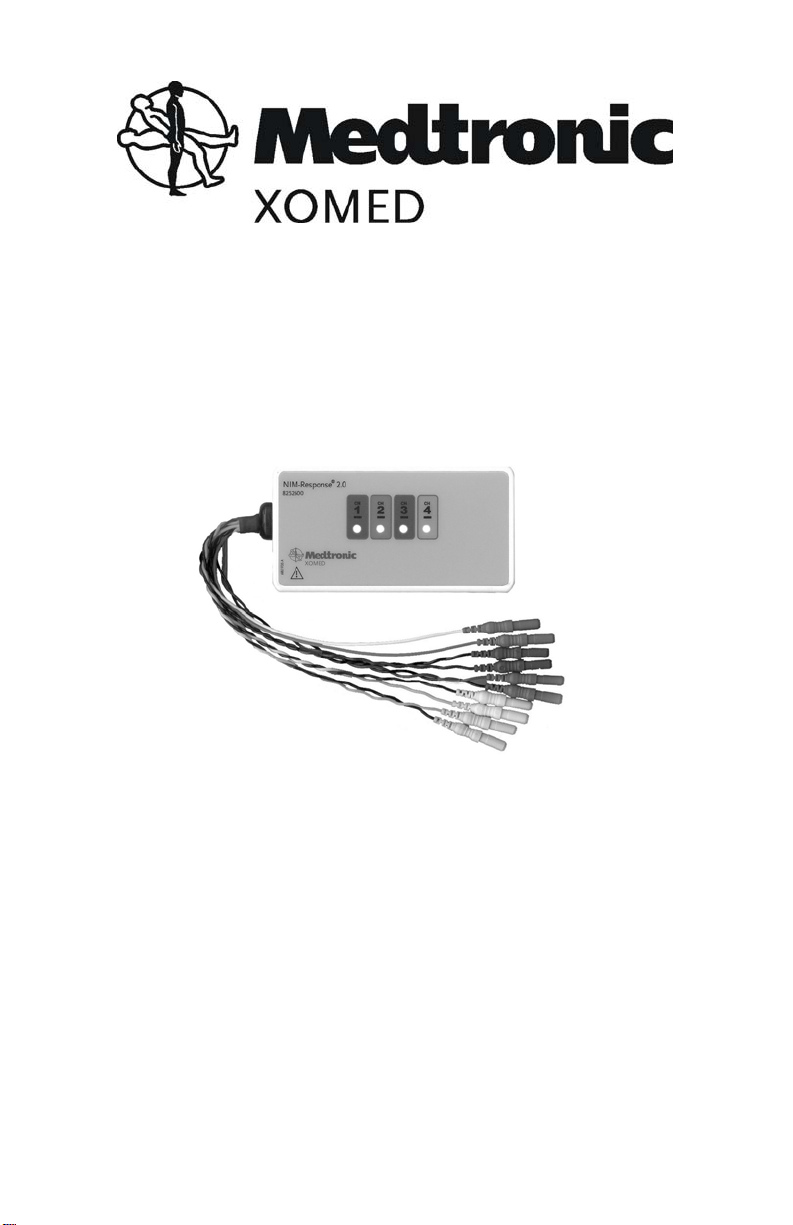
NIM-Response® 2.0 PATIENT SIMULATOR
Colored wires and connectors protrude from the end of the simulator. These cables connect to the corresponding
jacks on the NIM-Response® 2.0 Patient Interface.
On the NIM-Response® 2.0 Patient Simulator, there is one stimulation contact each, for Ch 1 through Ch 4. These
contacts are the points for activating individual circuits. A monopolar stimulator probe instrument (connected to
STIM1 - (negative)) is recommended for use during testing to stimulate the channel circuits.
NIM-Response® 2.0 P ATIENT INTERFACE CONNECTION
The NIM-Response® 2.0 Patient Interface and cable are the link between the NIM-Response® 2.0 and the NIMResponse® 2.0 Patient Simulator.
Positive Electrodes (colored
®
®
Fig 3
egative Electrodes (black
The colored Simulator cables are connected to the corresponding Patient Interface jacks as described in the Setup section of this manual. Refer to the NIM-Response® 2.0 User’s Guide for further details on operating the
NIM-Response® 2.0 Patient Interface and its features.
NIM-Response® 2.0
Fig 6
NIM-Response® 2.0
Fig 7
710

SYSTEM SETUP
N
®
SIMULA T OR SETUP
Simulator use requires prior setup of the NIM-Response® 2.0 unit as described in the NIM-Response® 2.0
User’s Guide. Be sure to follow all pertinent cautions, warnings, and operating instructions found in each
section of the User’s Guide.
Follow these steps to set up the system for Simulator use:
1. Connect all channel jumper cables from the simulator to the corresponding Patient Interface (Colored
connectors with colored wire to POSITIVE jacks, colored connectors with black wires to NEGATIVE
jacks).
2. Connect the red connector with white wire to the Stim 1 positive (+) jack on the Patient Interface.
3. Connect the green connector with green wire to the ground jack on the Patient Interface.
4. Connect a Monopolar stimulator to the Stim 1 negative (black) jack on the Patient Interface.
PATIENT SIMULATOR
PATIENT INTERFACE
Fig 4
Connector
Color
Blue Blue 1 Patient Interface Positive
Blue Black 1 Patient Interface Negative
Red Red 2 Patient Interface Positive
Red Black 2 Patient Interface Negative
Purple Purple 3 Patient Interface Positive
Purple Black 3 Patient Interface Negative
Orange Orange 4 Patient Interface Positive
Orange Black 4 Patient Interface Negative
Red White N/A Patient Interface Stim 1 +
Green Green N/A Patient Interface Ground
Wire Color Channel # Connects To
Wiring Referen ce
8 9

CONNECTING TO THE NIM-Response® 2.0 (FRONT AND REAR PANEL)
N
A
D
F
B
IM-Response® 2.0
C
E
G
Fig 5
A. TOUCH SCREEN displays EMG waveforms and controls many functions of the monitor.
B. SPEAKER provides audio alarms, acoustic EMG monitoring, and voice prompts.
C. SOFTWARE Version installed.
D. CURRENT date.
E. POWER CONNECTOR
F. PATIENT INTERFACE CONNECTOR
G. ON/OFF POWER SWITCH
1. Connect the “Patient Interface” to connector “F” on the back of the NIM-Response® 2.0.
2. Connect the “AC Power Cord” to connector “E”.
JACKSONVILLE,
FL

N
(
g
SYSTEM ASSESSMENT
CONFIRMING ELECTRODES
This check confirms that all electrode circuits are connected and functioning properly.
1. Turn on the “Power Switch”.
• The NIM-Response® 2.0
TOUCH THE SCREEN AT THIS TIME.
This process takes about 40 seconds.
2. The first touch screen to open will be the “Select Quick Setup” screen (see fig 6).
3. The next screen to open will be the “EMG Monitoring” screen (see fig 7).
°
• DO NOT TOUCH THE SCREEN AT THIS TIME.
• This default screen will turn off after about 40 seconds.
will perform a series of self test during the “Boot Up” process DO NOT
4. Press
° The monitoring screen will close and the electrodes screen will open.

Impedance
On/Off
indicator
Difference
Warning
Fig 8
Electrode
Select
3. Electrodes screen opens (fig 8). - At this display confirm:
• All channels are ON.
• All channels have “Subdermal Electrode” selected.
• Positive and negative impedance of all 4 channels is 5.0 kΩ ± 0.3 kΩ or 5.6 kΩ ± 0.3 kΩ.
• The difference in their values is 0.5 kΩ ± 0.3 kΩ.
• The impedance of the Ground is 10.0 kΩ ± 0.6 kΩ.
• The impedance of the Stimulus Return is 29.0 kΩ ± 4.0 kΩ.
• Warning “Monitoring is Disabled” is on and flashing.
There are ON/OFF indicators in the upper right of each channel button. ON = GREEN.
°
NIM-Response® 2.0
Impedance
Ground
Stimulus
Return
ELECTRODE LEAD OFF
This test simulates what happens when contact with an electrode is lost. (See fig 9)
Fig 9
NIM-Response® 2.0
1. Press .
2. Disconnect either lead from Channel 1(fig 9).
• Electrodes screen will close and EMG Monitoring screen will open.
• The touch screen displays a flashing Channel 1.
• The touch screen displays a Warning in the center of the screen.
• After 20 to 30 seconds, the NIM-Response® 2.0 sounds the “Bleedle” alarm (a three-note alarm “BLEEdle DEET”) and enunciates “Check Electrodes”.

3. The Electrodes Screen opens (fig 10).
N
Fig 10
NIM-Response® 2.0
• The touch screen (fig 10) displays a flashing Channel 1.
• The touch screen displays a flashing Warning.
• Channel 1 will display “Off” for “Impedance” and “- - - - -” for “Difference”.
• The Bleedle Alarm sounds every twenty (20) seconds.
4. Reconnect the Channel 1 lead.
• Confirm: the NIM-Response® 2.0 returns to normal operation.
5. Repeat the test for Channels 2 through 4.
STIMULATION
MECHANICAL STIMULATION
The positive and negative jumper cables for Channels 1 through 4 are sensitive to touch (Mechanical
Stimulation) and will generate EMG and coded tone responses when manipulated. These simulated responses
appear as spontaneous burst-like responses in both the audio and visual signals.
1. Press
.
2. EMG Monitoring Screen will
open.
3. Lightly tap the jumper
cables.
• Observe:
You should hear single beep
°
alarms at each channel tapped.
Alarm tones change at each
°
channel.
You should see sharp (spike like)
°
waveforms on the screen.
Tapping multiple cables will
°
produce multiple alarms and
waveforms. (see fig 11)
IM-Response® 2.0
Fig 11

EMG STIMULATING AND TONES
t
d
tnd
1. Increase EMG Stim to 1.0 mA (see fig 12).
a. In the upper right of the screen, press the EMG Stim (0.0 mA) button.
b. This will open a dropdown menu consisting of five buttons, four
s
1
arrow and one zero.
c. Press the SMALL up arrow until 1.0 mA is displayed on the EMG
Stim button.
d. Buttons will turn off after a few seconds.
2. Touch and hold the stimulating probe to channel 1 of the Patient Simulator.
• Observe: (see fig 13)
Waveform on channel 1.
°
Stimulus tone sounds (repeating beep).
°
Raw EMG can be heard (a popping sound accompanying the
°
stimulus tone).
mA Measured is 1.0 mA ± 0.02 mA or 5% of applied mA.
3. While maintaining contact with the simulator, increase the Event Threshold (see fig 14, use large up
°
arrow) until the stimulus pulse no longer triggers a tone.
• Note that the raw EMG can still be heard (a popping sound).
4. Remove probe. Note that waveform remained on screen (if not check Event Thresholds button’s on/off
indicator is green).
5. Repeat for remaining channels.
2
Fig 12
n
Fig 13
BASELINE TEST
1. Decrease Event Threshold to 20μV
(see fig 14).
a. In the upper right of the screen, press the Event Threshold
button.
b. This will open a dropdown menu consisting of four arrow
buttons.
c. Press the LARGE down arrow until 20 μV is displayed on the
Event Threshold button.
d. Buttons will turn off after a few seconds.
At this point, the monitor will be picking up large amounts
of electronic noise causing multiple event tones to sound.
It is also helpful to hold the channel 1 electrode between
two fingers.
2. Press (on/off indicator turns green).
• Observe continuous event alarms sounding for 20-30 seconds.
• After 20-30 seconds, Baseline Increase is announced.
• Baseline activity is displayed on the screen.
NOTE: Vary the Audio and other settings used in this test to become more familiar with the NIM.
NIM-Response® 2.0
s
Fig 14

CLEANING
• The Patient Simulator enclosure is not waterproof. DO NOT immerse the Patient Simulator.
• DO NOT attempt to sterilize the Patient Simulator.
• Dampen a soft cloth with disinfectant or mild detergent and water.
• Thoroughly wipe the Patient Simulator and cables, removing all visible debris.
• Allow the Patient Simulator to thoroughly air dry before storing.
NOTE: Cloth must not be dripping wet.
°
TROUBLESHOOTING
Should you encounter any difficulty eliciting simulated responses from the NIM-Response® 2.0 PATIENT
SIMULATOR, check the following:
• Verify that Stimulus Measured is approximately the same as Stimulus Intensity.
• Make sure the jumper cables are connected correspondingly between the SIMULATOR and
PATIENT INTERFACE.
• Adjust the EVENT THRESHOLD setting on the NIM-Response® 2.0.
• Adjust the STIMULUS intensity on the NIM-Response® 2.0 for adequate output.
• Clean the stimulator contacts of debris.
• Check the integrity of the stimulator or stimulus-dissection instrument and its connecting cable.
• Check for blown fuse in NIM-Response® 2.0 Patient Interface and replace with proper valued fuse
(shown near fuse box).
• Check for proper closure of fuse holder in the NIM-Response® 2.0 Patient Interface.


Medtronic Xomed, Inc.
6743 Southpoint Drive North
Jacksonville, Florida 32216-0908 U.S.A.
www.xomed.com
68E3792 Rev A 10/03
16
 Loading...