

Page 1
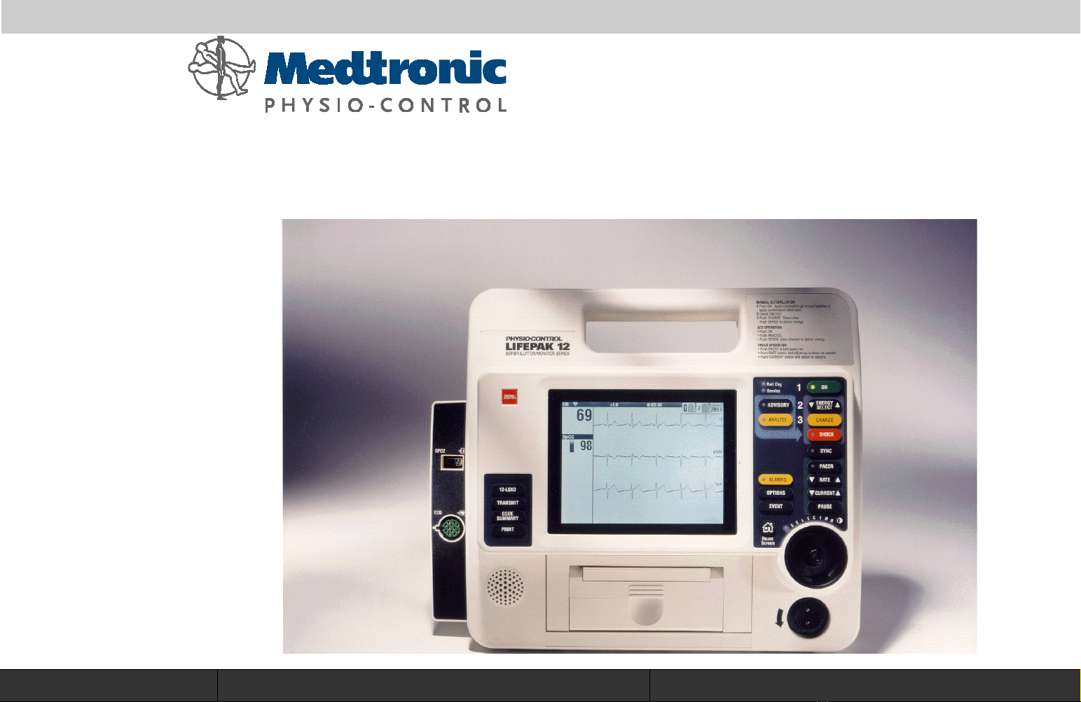
LIFEPAK
12
defibrillator/monitor series
®
Service Manual
Click Here for Table of Contents Click Here for Navigation Help
Page 2

LIFEPAK 12 defibrillator/monitor series Table of Contents
Click a Topic
Preface
Modes of
Operation
Preventive
Maintenance
Safety
Performance
Inspection
Battery
Maintenance
Device
Description
Instrument
Calibration
Replacement
Procedures
Operating
Instructions
Troubleshooting
Parts Lists and
Assembly
Diagrams
Index
2
Title Page
Back
Index Next Page
Page 3

LIFEPAK 12 defibrillator/monitor series Section Contents
Preface
This Service Manual describes how to maintain, test, troubleshoot, and repair
the LIFEPAK 12 defibrillator/monitor. A separate publication, the LIFEPAK 12
defibrillator/monitor series Operating Instructions, is for use by physicians,
clinicians, and emergency care providers. The Operating Instructions provide
step-by-step instructions as well as operator-level testing and maintenance.
Note:
message, or screen overlay appears as small caps. For example,
control and
This section covers the following topics:
Hyperlinks appear in Blue Text. Text that indicates a control, menu,
ADVISORY
SETUP
Menu.
Trademarks
Service Personnel Qualifications
Contacting Medtronic Physio-Control
Responsibility for Information
Device Tracking
Service Information
Recycling Information
Warranty
Configuration Information
Glossary
3
Previous Page Table of Contents
Acronyms
Back
Index Next Page
Page 4

LIFEPAK 12 defibrillator/monitor series Preface
Trademarks
PHYSIO-CONTROL, LIFEPAK, FASTPAK, and DERMA JEL are registered trademarks of
Medtronic Physio-Control Corp.
QUIK-COMBO, CODE SUMMARY, CODE-STAT Suite, QUIK-VIEW, DATA TRANSFER,
REDI-PAK, FAST-PATCH, PARTSLINE, Shock Advisory System, and the Medtronic
Physio-Control 3D Biphasic technology trademark are trademarks of Medtronic
Physio-Control Corp.
Medtronic is a registered trademark of Medtronic, Inc.
MICROSOFT and WINDOWS are registered trademarks of Microsoft Corporation in the US
and/or other countries.
Pentium is a trademark of Intel Corporation.
Adobe and Acrobat are trademarks of Adobe Systems Incorporated.
12SL and Muse CV are trademarks of Marquette Medical Systems.
Oridion is a protected trademark and Microstream and FilterLine are trademarks of Oridion
Medical Ltd.
C-LOCK is a registered trademark of Nellcor Puritan Bennett.
Tektronix is a registered trademark of Tektronix Incorporated.
BIO-TEK is a registered trademark of Bio-Tek Instruments, Inc. QED is a trademark of BioTek Instruments, Inc.
Black Box is a registered trademark of Black Box Corporation.
3Com and Megahertz are registered trademarks of 3Com Corporation.
Motorola is a registered trademark of Motorola, Inc.
PC Card is a trademark of the Personal Computer Memory Card International Association.
Duracell is a registered trademark of Duracell, a wholly-owned subsidiary of The Gillette Co.
Specifications are subject to change without notice.
© 1998–2001 Medtronic Physio-Control Corp. All rights reserved.
4
PN 3010013-015
Previous Page Table of Contents Section Contents
Back
Index Next Page
Page 5

LIFEPAK 12 defibrillator/monitor series Preface
Service Personnel Qualifications
Technicians who service the device must be properly qualified and thoroughly
familiar with the operation of the LIFEPAK 12 defibrillator/monitor. Technicians
must meet at least one of the following requirements (or the equivalent):
■
Associate of Applied Science, with an emphasis in biomedical electronics
■
Certificate of Technical Training, with an emphasis in biomedical electronics
■
Equivalent biomedical electronics experience
5
Previous Page Table of Contents Section Contents
Back
Index Next Page
Page 6

LIFEPAK 12 defibrillator/monitor series Preface
Contacting Medtronic Physio-Control
Medtronic Physio-Control
11811 Willows Road Northeast
Post Office Box 97006
Redmond, WA 98073-9706 USA
Telephone: 1.425.867.4000
Toll Free (USA only): 1.800.442.1142
Fax: 1.425.867.4121
Internet: www.physiocontrol.com
www.medtronic.com
Europe
Medtronic Physio-Control
Rte. Du Molliau 31
1131 Tolochenaz
Switzerland
Telephone: 41.21.802.7000
Fax: 41.21.802.7900
6
Previous Page Table of Contents Section Contents
Back
Index Next Page
Page 7

LIFEPAK 12 defibrillator/monitor series Preface
Responsibility for Information
This Service Manual describes the methods required to maintain, test, and
repair the LIFEPAK 12 defibrillator/monitor. This manual does not cover
operation of the LIFEPAK 12 defibrillator/monitor. Qualified service personnel
must consult both the LIFEPAK 12 defibrillator/monitor series Operating
Instructions and the LIFEPAK 12 defibrillator/monitor series Service Manual to
obtain a complete understanding of the use and maintenance of the device.
It is the responsibility of our customers to ensure that the appropriate person(s)
within their organization have access to the information in this Service Manual,
including any warnings and cautions used throughout the LIFEPAK 12
defibrillator/monitor series Service Manual.
7
Previous Page Table of Contents Section Contents
Back
Index Next Page
Page 8

LIFEPAK 12 defibrillator/monitor series Preface
Device Tracking
USA only, including US government-owned devices:
The Food and Drug Administration requires defibrillator manufacturers and
distributors to track the location of defibrillators. If your defibrillator has been
sold, donated, lost, stolen, exported, or destroyed, or if it was not obtained
directly from Medtronic Physio-Control, please notify Medtronic Physio-Control
at 1.800.442.1142, extension 4530.
General information related to device tracking:
It is important to maintain accurate records of defibrillator location within your
facility or system. Maintenance of such records eases the process of locating
defibrillators should it be necessary to modify them. Defibrillators should be
tracked by both the manufacturer’s part and serial number. Internal asset or
tracking numbers may also be useful in maintaining adequate control of
defibrillators.
8
Previous Page Table of Contents Section Contents
Back
Index Next Page
Page 9

LIFEPAK 12 defibrillator/monitor series Preface
Service Information
Before attempting to clean or repair any assembly in this device, the technician
should be familiar with the information provided in the Preventive Maintenance
section.
A qualified technician should inspect any defibrillator that has been dropped,
damaged, or abused to verify that the device is operating within performance
standards listed in the Performance Inspection Procedure (PIP), and that the
leakage current values are acceptable.
Replacement procedures for the LIFEPAK 12 defibrillator/monitor are limited to
those items accessible at the final assembly level. Replacements and
adjustments must be made by service personnel qualified by appropriate
training and experience. Replacements at the final assembly level simplify repair
and servicing procedures, and help ensure correct device operation and
calibration.
To obtain Medtronic Physio-Control service and maintenance for your
LIFEPAK 12 defibrillator/monitor, contact your local service or sales
representative. In the USA, call Medtronic Physio-Control Technical Services at
1.800.442.1142. Outside the USA, contact your local Medtronic Physio-Control
representative.
9
Previous Page Table of Contents Section Contents
Back
Index Next Page
Page 10

LIFEPAK 12 defibrillator/monitor series Preface
Recycling Information
Recycle the device at the end of its useful life.
■
Recycling Assistance – The device should be recycled according to national
and local regulations. Contact your local Medtronic Physio-Control
representative for assistance.
■
Preparation – The device should be clean and contaminant-free prior to
being recycled.
■
Recycling of Disposable Electrodes – After using disposable electrodes,
follow your local clinical procedures for recycling.
■
Recycling of Batteries – The device uses rechargeable FASTPAK,
FASTPAK 2 NiCd (Nickel-Cadmium) and LIFEPAK NiCd, and LIFEPAK SLA
(sealed lead-acid) batteries. Follow local guidelines and instructions given in
this Service Manual for discarding/recycling batteries.
■
Packaging – Save or recycle packaging materials.
10
Previous Page Table of Contents Section Contents
Back
Index Next Page
Page 11

LIFEPAK 12 defibrillator/monitor series Preface
Warranty
Refer to the Warranty statement included in the Operating Instructions –
Maintaining the Equipment.
11
Previous Page Table of Contents Section Contents
Back
Index Next Page
Page 12

LIFEPAK 12 defibrillator/monitor series Preface
Configuration Information
This Service Manual covers existing LIFEPAK 12 defibrillator/monitor series
devices and options through the following revisions:
■
LIFEPAK 12 Monophasic Basic Device with ECG
■
LIFEPAK 12 Biphasic Basic Device with ECG
■
Pacing Option
■
SpO2 Option
■
12-Lead Option
■
NIBP Monitor Option
■
EtCO2 Option
■
Fax/Data Communication Option
■
ElectroLuminescent (EL) Display Option
■
Invasive Pressure Option
■
Vital Signs Trending Option
12
Previous Page Table of Contents Section Contents
Back
Index Next Page
Page 13

LIFEPAK 12 defibrillator/monitor series Preface
Glossary Page 1 of 3
The following are definitions of terms used throughout this Service Manual.
■
Automated External Defibrillator (AED) — The LIFEPAK 12 defibrillator/
monitor uses an ECG analysis Shock Advisory System (SAS) to advise the
device operator if it detects a shockable or nonshockable rhythm. For more
information about CPSS and SAS, see
Operating Instructions – Shock
the
Advisory System
■
Biphasic — Property of the shock waveform generated by the LIFEPAK 12
biphasic defibrillator/monitor. The biphasic waveform is characterized by a
positive current phase followed by a reverse current phase of shorter
duration and decreased magnitude. The waveform pulse characteristic is
biphasic truncated exponential (BTE).
■
CODE SUMMARY™ Report — A summary report that includes the ECG
segments associated with key events such as analysis or shock. See the
Operating Instructions — Data Management for a sample CODE
SUMMARY Report.
13
.
Previous Page Table of Contents Section Contents
Back
Index Next Page
Page 14

LIFEPAK 12 defibrillator/monitor series Preface
Glossary Page 2 of 3
■
Continuous Patient Surveillance System (CPSS) — A feature that monitors
the patient ECG in
LEADS
PADDLES
or
for a potentially shockable rhythm.
CPSS is active when the front panel
VF/VT ALARM
the
is selected after pressing the
ADVISORY
indicator is on (AED Mode) or
ALARMS
control (Manual Mode).
The CPSS operates in conjunction with the Shock Advisory System (SAS).
For more information about CPSS and SAS, see
Instructions — Shock Advisory System
■
Edmark — Property of the shock waveform generated by the LIFEPAK 12
.
Operating
the
Monophasic defibrillator/monitor. The Edmark pulse characteristic is
monophasic damped sinusoid (MDS) per AAMI DF2-1989 3.2.1.5.1.
■
End-Tidal Carbon Dioxide (EtCO2) — A noninvasive capnometer that
monitors EtCO2, FiCO2, and respiration rate.
■
Event Log Summary — A report summarizing important events for a
particular patient record; part of the CODE SUMMARY Report.
■
FAST-PATCH™ disposable defibrillation/ECG electrodes — An electrode
system that allows delivery of defibrillation therapy to the patient.
■
Monophasic — See Edmark.
■
Noninvasive Blood Pressure (NIBP) — An optional meter that checks
systolic, diastolic, and mean arterial blood pressure, along with pulse rate.
■
QUIK-COMBO™ pacing/defibrillation/ECG electrodes — An electrode
14
Previous Page Table of Contents Section Contents
system that allows delivery of pacing and defibrillation therapy to the patient.
Back
Index Next Page
Page 15

LIFEPAK 12 defibrillator/monitor series Preface
Glossary Page 3 of 3
■
QUIK-COMBO patient simulator — A combination lead tester/patient cardiac
rhythm simulator. The simulator is designed for use in training clinical
personnel in the operation of the LIFEPAK 12 defibrillator/monitor.
■
REDI-PAK™ preconnect system — A variant of the QUIK-COMBO pacing/
defibrillation/ECG electrodes system. The system allows QUIK-COMBO
pacing/defibrillation/ECG electrode cable connection without removing the
electrodes from their air-tight sealed pouch until needed.
■
Shock Advisory System (SAS) — A computerized ECG analysis system for
use in the detection of a shockable rhythm. For more information about
CPSS and SAS, see
System
■
SpO2 — A noninvasive pulse oximeter that checks the saturation of oxygen
.
Operating Instructions — Shock Advisory
the
in arterial blood.
■
Test Load — A device that provides an external defibrillation test load for the
defibrillator/monitor. The test load connects to the patient connector on the
device.
15
Previous Page Table of Contents Section Contents
Back
Index Next Page
Page 16

LIFEPAK 12 defibrillator/monitor series Preface
Acronyms Page 1 of 4
The following is a list of acronyms and abbreviations used in this manual.
Term Description
AAMI Association for the Advancement of Medical Instrumentation
ADC Analog-to-Digital Conversion
AED Automated External Defibrillator
A/H Amp/Hours: A measure of battery capacity
AHA American Heart Association
AMI Acute Myocardial Infarction
ANSI American National Standards Institute
ASIC Application-Specific Integrated Circuit
BTE Biphasic Truncated Exponential
BF Electrically isolated, external body connection
BPM Beats Per Minute
CF Electrically isolated, direct cardiac connection
CPR Cardiopulmonary Resuscitation
CPU Central Processing Unit
CPSS Continuous Patient Surveillance System
DDE Disposable Defibrillation Electrodes
16
Previous Page Table of Contents Section Contents
DSP Digital Signal Processor
Back
Index Next Page
Page 17

LIFEPAK 12 defibrillator/monitor series Preface
Acronyms Page 2 of 4
.
Term Description
DUART Dual Universal Asynchronous Receiver/Transmitter
DMM Digital Multimeter
ECG Electrocardiogram
EMS Emergency Medical Service
ESCC Energy Storage Capacitor Charger
ESD Electrostatic Discharge
ESU Electrosurgical Unit
EtCO2 End-Tidal Carbon Dioxide
FiCO2 Inspired Carbon Dioxide
HR Heart Rate
IEC International Electrical Commission
IP Invasive Pressure
LCD Liquid Crystal Display
LED Light Emitting Diode
MDS Monophasic Damped Sinusoidal
MMHg Millimeters of Mercury
NIBP Noninvasive Blood Pressure
17
Previous Page Table of Contents Section Contents
NiCd Nickel-Cadmium (battery)
Back
Index Next Page
Page 18

LIFEPAK 12 defibrillator/monitor series Preface
Acronyms Page 3 of 4
Term Description
NHAAP National Heart Attack Alert Program
NSR Normal Sinus Rhythm
OEM Original Equipment Manufacturer
RR Respiration Rate
PC Personal Computer
PCB Printed Circuit Board
PCMCIA Personal Computer Memory Card International Association
PIP Performance Inspection Procedure
PPM Pulses Per Minute
QRS Refers to portions of the ECG waveform
RISC Reduced Instruction Set Computer
RTC/
NVRAM
RTS Radio Transparent System
SAS Shock Advisory System
SLA Sealed Lead-Acid (battery)
SpO2 Pulse Oximeter reading (saturation of oxygen in arterial blood)
18
Previous Page Table of Contents Section Contents
SSD Static-Sensitive Device
Real Time Clock/Non-Volatile Random-Access Memory
Back
Index Next Page
Page 19
LIFEPAK 12 defibrillator/monitor series Preface
Acronyms Page 4 of 4
Term Description
TCP Test and Calibration Procedure
UUT Unit Under Test
VF Ventricular Fibrillation
VT Ventricular Tachycardia
µA MicroAmpere
19
Previous Page Table of Contents Section Contents
Back
Index Next Page
Page 20

LIFEPAK 12 defibrillator/monitor series Section Contents
Safety
The Safety section describes the general safety conventions, terms, and
symbols used in this Service Manual or on the LIFEPAK 12 defibrillator/monitor
front and rear panels. This information is intended to alert service personnel to
recommended precautions in the care, use, and handling of this specialized
medical device.
Terms
General Warnings and Cautions
Symbols
20
Previous Page Table of Contents
Back
Index Next Page
Page 21

LIFEPAK 12 defibrillator/monitor series Safety
Ter ms
The following terms are used in this Service Manual or on the various
configurations of the LIFEPAK 12 defibrillator/monitor. Familiarize yourself with
their definitions and significance.
Danger: Immediate hazards that will result in serious personal injury or death.
Warning: Hazards or unsafe practices that could result in serious personal injury
or death.
Caution: Hazards or unsafe practices that could result in device or property
damage.
Note:
operation; additional information or explanation concerning the subject under
discussion.
21
Previous Page Table of Contents Section Contents
Points of particular interest for more efficient or convenient device
Back
Index Next Page
Page 22

LIFEPAK 12 defibrillator/monitor series Safety
General Warnings and Cautions Page 1 of 2
The following are general warnings and cautions. Keep these warnings and
cautions in mind when working with the LIFEPAK 12 defibrillator/monitor. More
specific warnings and cautions appear throughout this Service Manual and the
LIFEPAK 12 defibrillator/monitor Operating Instructions.
WARNINGS!
Possible fire or explosion. Do not service this device in the presence of
flammable gases, anesthetics, or oxygen sources.
Shock or fire hazard. Do not immerse any portion of this device in water or
other fluids. Avoid spilling any fluids on the device or accessories. If the
device is ever immersed in water or other fluids, remove the batteries and
disconnect input power source from any attached AC or DC Power Adapter
until the device can be serviced.
Patient hazard. Do not mount the device directly above patient. Place the
device in a location where it cannot harm the patient should it fall from its
shelf or other mount.
Shock or fire hazard. Equipment or accessories improperly interconnected
to each other can be a source of ignition or cause a shock. Make sure that
all equipment is interconnected safely.
22
Previous Page Table of Contents Section Contents
Back
Index Next Page
Page 23

LIFEPAK 12 defibrillator/monitor series Safety
General Warnings and Cautions Page 2 of 2
WARNING!
Shock hazard. Servicing of this device must be performed by properly
trained individuals. This device may retain potentially lethal charges
accessible inside the device at any time–even when off. Follow procedures
carefully for discharging the A15 Energy Storage Capacitor and the Pacing
Capacitor on the A04 Therapy PCB.
CAUTIONS!
Possible equipment damage. This device may be damaged by mechanical
or physical abuse such as immersion in water or dropping. If the device
has been abused, remove it from use and contact qualified service
personnel.
Possible device damage. To help prevent component damage, do not
mount the device near vibration sources such as engine struts or landing
gear.
23
Previous Page Table of Contents Section Contents
Back
Index Next Page
Page 24
LIFEPAK 12 defibrillator/monitor series Safety
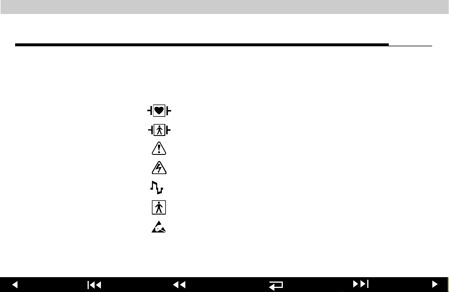
Symbols Page 1 of 7
The following list includes symbols that may be used in this Service
Manual or on various configurations of the LIFEPAK 12 defibrillator/monitor
and accessories. Some symbols may not be relevant to your device or used in
every country.
Defibrillation-proof type CF terminal
Defibrillation protected, type BF patient connection
Attention, consult accompanying documents
Warning, high voltage
Biphasic defibrillation shock
Type BF patient connection
Static-sensitive device (SSD)
24
Previous Page Table of Contents Section Contents
Back
Index Next Page
Page 25
LIFEPAK 12 defibrillator/monitor series Safety
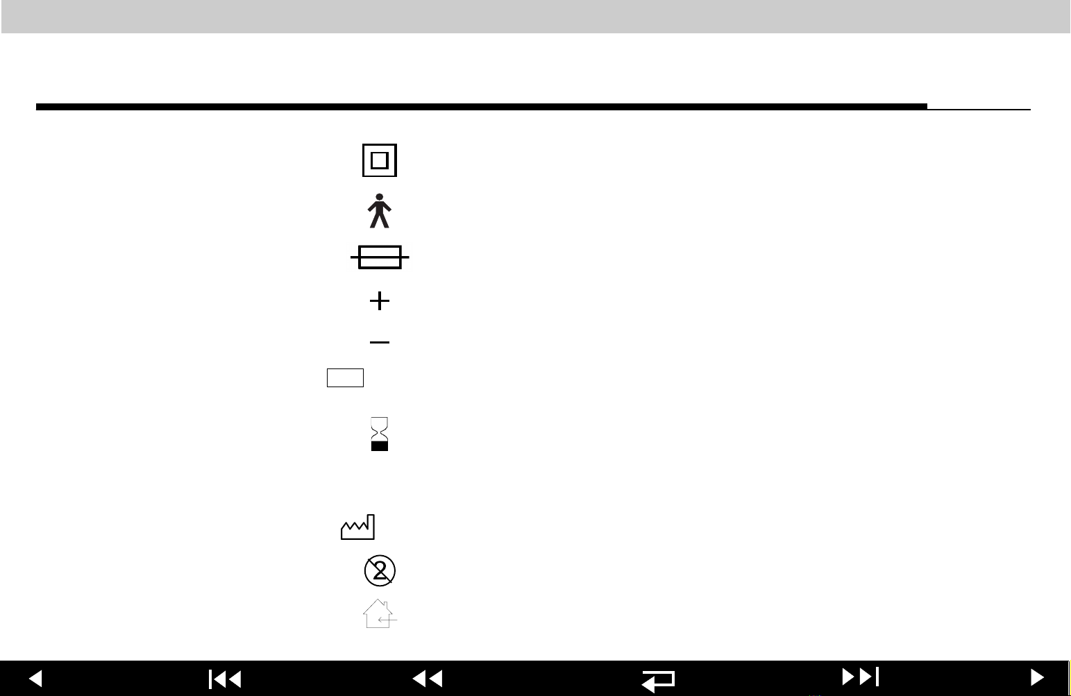
Symbols Page 2 of 7
Safety Class II equipment (reinforced insulation)
Type B equipment
Fuse
Positive terminal
Negative terminal
YYWW
LOT
Lot number (batch code)
Use by expiration date
REF
YYYY
Reorder number (catalog number)
Date of manufacture
Single use only
25
Previous Page Table of Contents Section Contents
Indoor use only
Back
Index Next Page
Page 26
LIFEPAK 12 defibrillator/monitor series Safety
Symbols Page 3 of 7
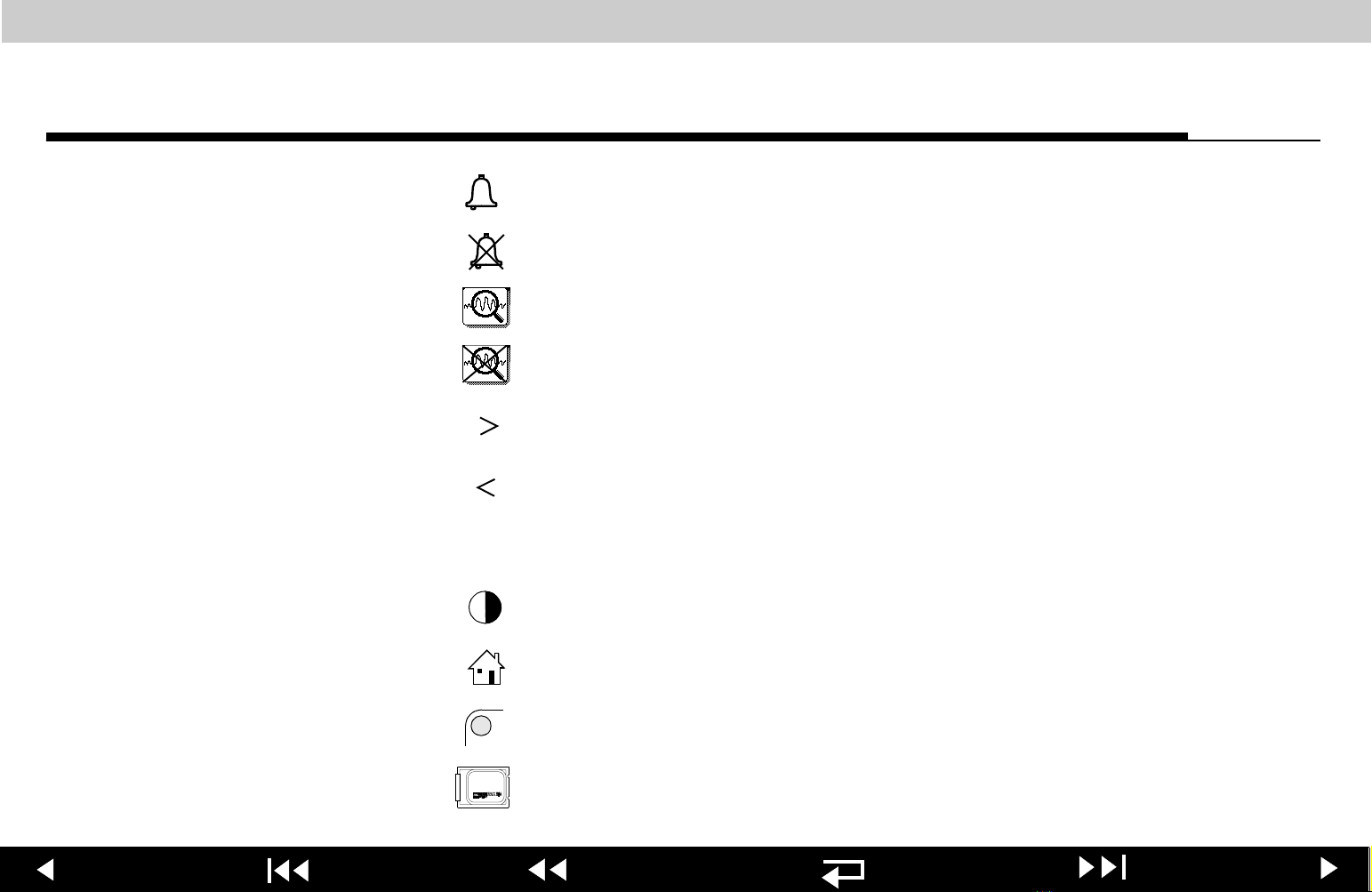
Alarm on
Alarm off
VT alarm on
VF/
VF/
VT alarm silenced or suspended
Greater than
Less than
J
Joules
LCD Contrast control
Home screen button
Selector indicator
26
Previous Page Table of Contents Section Contents
LIFEPAK SLA battery
Back
Index Next Page
Page 27
LIFEPAK 12 defibrillator/monitor series Safety
Symbols Page 4 of 7
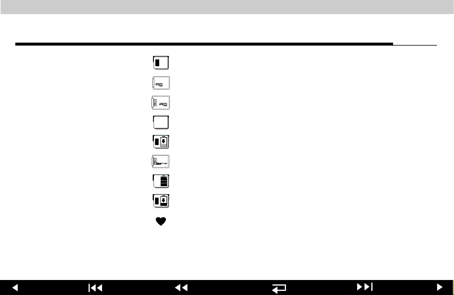
1
FASTPAK or LIFEPAK SLA battery in well 1, in use
FASTPAK battery
FASTPAK 2 battery
2
1
FASTPAK or LIFEPAK SLA battery in well 2, not in use
FASTPAK or LIFEPAK SLA battery in well, discharged
LIFEPAK NiCd battery
2
2
1
LIFEPAK NiCd battery in well, fully charged, not in use
LIFEPAK NiCd battery in well, discharged
Heart rate/pulse rate indicator
27
Previous Page Table of Contents Section Contents
Back
Index Next Page
Page 28
LIFEPAK 12 defibrillator/monitor series Safety
Symbols Page 5 of 7
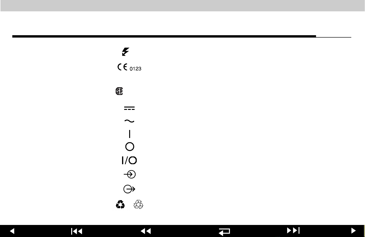
(x)
NRTL/C
Shock count (x) on screen
Marking of conformity according to the Medical Device
Directive 93/42/EEC by notified body TÜV Product Service
GmbH
Canadian Standards Association certification for United
States (Nationally Recognized Test Laboratory) and Canada
DC voltage
AC voltage
On (power: connection to the AC mains)
Off (power: disconnection from the AC mains)
Power on/off
[signal] Input
[signal] Output
or
28
Previous Page Table of Contents Section Contents
Recycle this product
Back
Index Next Page
Page 29
LIFEPAK 12 defibrillator/monitor series Safety
Symbols Page 6 of 7
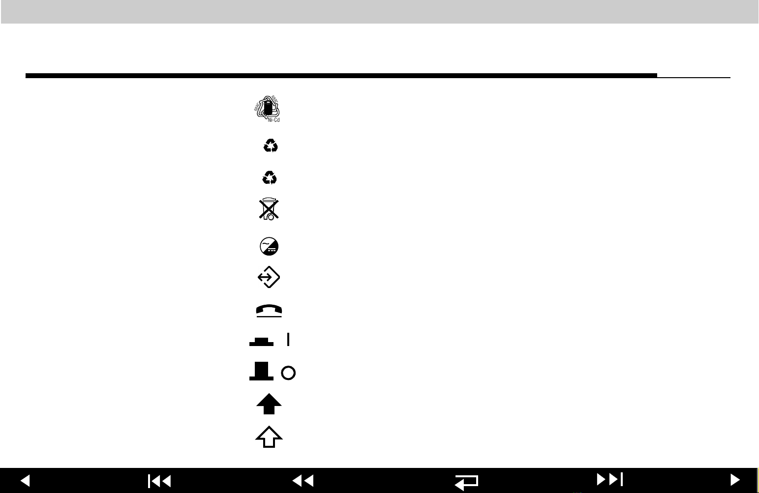
Recycle NiCd battery
NiCd
Recycle Nickel Cadmium battery
Pb
Recycle Lead-acid battery
See instructions for recycling instructions
See instructions for disposal procedure
AC to DC adapter
System connector
Telephone line connector
Switch on
Switch off
Pace arrow, noninvasive pacing
29
Previous Page Table of Contents Section Contents
Pace arrow, internal pacing
Back
Index Next Page
Page 30
LIFEPAK 12 defibrillator/monitor series Safety
Symbols Page 7 of 7
R-wave sense marker
Event marker
CO2 exhaust
CO2
Chassis ground
Recognized component mark for Canada and the United
States
LIFEPAK 12 to LIFEPAK 12 cable
!USA
30
Previous Page Table of Contents Section Contents
For USA audiences only
Back
Index Next Page
Page 31

LIFEPAK 12 defibrillator/monitor series Section Contents
Device
Description
This section describes how the LIFEPAK 12 defibrillator/monitor works. Topics
include input signals, assembly functions, and device outputs. This section also
provides a description of the physical characteristics and functionality of the
LIFEPAK 12 defibrillator/monitor.
Introduction
Physical Description and Features
Ordering Devices, Supplies, and Accessories
System Context Diagram
Functional Description
31
Previous Page Table of Contents
Back
Index Next Page
Page 32

LIFEPAK 12 defibrillator/monitor series Device Description
Introduction Page 1 of 5
About the Device
Energy Waveforms
Energy Delivery
The LIFEPAK 12 defibrillator/monitor is a complete acute cardiac care response
system with both manual and semi-automatic defibrillation operation. When
clinically indicated, the LIFEPAK 12 defibrillator/monitor allows the operator to
deliver a brief, high-energy pulse of electricity to the heart of the patient.
Operators may pre-configure the device to reduce complexity during normal
operation. Built-in service features include self-calibration and testing.
The LIFEPAK 12 defibrillator/monitor series includes two distinct versions
characterized by different defibrillator waveform technologies: monophasic and
biphasic. The Monophasic (Edmark) device generates a monophasic damped
sinusoidal (MDS) shock pulse, while the Biphasic device generates a biphasic
truncated exponential (BTE) shock pulse for defibrillation.
The LIFEPAK 12 defibrillator/monitor standard method of energy delivery is
through self-adhesive QUIK-COMBO pacing/defibrillation/ECG electrodes.
When using these disposable defibrillation electrodes (DDEs), internal circuitry
continuously measures the impedance between the electrodes and allows
defibrillation only when the defibrillation electrodes are attached to the patient.
The user may select from a variety of optional accessories for energy delivery
(for example, standard hard paddles or internal paddles).
32
Previous Page Table of Contents Section Contents
Back
Index Next Page
Page 33

LIFEPAK 12 defibrillator/monitor series Device Description
Introduction Page 2 of 5
Manual Mode Operation
Advisory Mode
Operation
In Manual Mode (
manually select an energy level, initiate a charge sequence, and apply energy in
either direct or synchronized modes. When the operator selects the
from the
monitors the patient’s ECG for a shockable rhythm. A suspect rhythm alerts the
operator with a priority tone and screen overlay. The operator can then follow
locally established guidelines for the administration of defibrillation therapy.
In the Advisory Mode (
monitor the patient’s ECG for a shockable rhythm. A suspect rhythm alerts the
operator with a priority tone and screen overlay. The operator may continue by
pressing the
analyze the ECG rhythm and make recommendations. The operator can then
follow locally established guidelines for the administration of defibrillation
therapy. For more information about CPSS and SAS, see the Operating
Instructions, Appendix D
ALARMS
ANALYZE
ADVISORY
Menu, the Continuous Patient Surveillance System (CPSS)
control, which allows the Shock Advisory System (SAS) to
indicator off), the device allows the operator to
ADVISORY
.
indicator on), the device uses the CPSS to
VF/VT ALARM
33
Previous Page Table of Contents Section Contents
Back
Index Next Page
Page 34

LIFEPAK 12 defibrillator/monitor series Device Description
Introduction Page 3 of 5
Device Primary
Functions
The device has six primary functions:
■
Defibrillation
– Manual or semi-automatic (AED) defibrillation
– Leads off detection for therapy and ECG electrodes
– Synchronized Cardioversion
■
Noninvasive Pacing
– Demand and Nondemand modes of operation
■
Capture Patient Information
– Stores both patient and device data at each event
– Real-time clock provides time stamps for events
– Provides operator review of stored events for printout or transmission
■
Patient Signal Monitoring
– ECG monitoring–displays up to three ECG waveforms at once
– Pulse Oximetry (SpO2) monitoring, continuous display
– Heart rate monitoring, continuous display
– Noninvasive blood pressure (NIBP) monitoring, continuous display
– Invasive pressure (IP) monitoring, continuous display
– Capnography (EtCO2 and RR) monitoring, continuous display
– Waveforms display pace and sense markers
34
Previous Page Table of Contents Section Contents
– Ventricular Fibrillation/Ventricular Tachycardia monitoring and alarm
Back
Index Next Page
Page 35

LIFEPAK 12 defibrillator/monitor series Device Description
Introduction Page 4 of 5
■
Device Primary
Capture and Analyze 12-lead ECG
Functions (continued)
– Captures up to 45 minutes of continuous ECG data
– Continuous printing of ECG data
– Transmit ECG data to a remote site
– Acquire and analyze 12-lead data
■
Manage Alarms and Warnings
– Places alarm limits on patient monitoring parameters
– Automatic alarm limit reset at operator request
– Activates or disables alarms and stores alarm events
– Silence alarms for up to 15 minutes
– Visual indicators and audible tones in alarm conditions
Service features include calibration and diagnostic functions.
35
Previous Page Table of Contents Section Contents
Back
Index Next Page
Page 36

LIFEPAK 12 defibrillator/monitor series Device Description
Introduction Page 5 of 5
Assemblies
36
The LIFEPAK 12 defibrillator/monitor consists of a two-piece case assembly that
encloses the following printed circuit boards (when fully configured with options):
1. A01 System PCB
2. A02 Memory PCB
3. A03 Power PCB
4. A04 (Edmark) / A04 (Biphasic)
Therapy PCB
5. A05 Interface PCB
6. A06 OEM PCB
... and the following subassemblies:
1. A09 Small Keypad
2. A10 Large Keypad
3. A11 (LCD) / A11 (EL) Display
Assembly
4. A12 Printer Assembly
5. A13 Transfer Relay Assembly
In addition, there are two battery wells, W10 Battery Pins (4x), W07 ECG
Connector Cable, W08 System Connector Cable, W09 Auxiliary Connector
Cable, W11 Therapy Connector Cable, W22 SpO2 Connector Cable, W15
Selector Assembly, W17 Speaker Assembly, C15 Pacing Capacitor, and
associated labels, wiring, and hardware. See the Interconnect Drawing—
Edmark or Interconnect Drawing—Biphasic.
7. A07 Contact PCB
8. A08 Backlight PCB (LCD)
9. A16 SpO2 Module
10. A21 NIBP Module
11. A22 Biphasic PCB (Biphasic)
12. A23 EtCO2 Module
6. A14 Waveshaping Inductor
(Edmark) / A14 Inductive
Resistor (Biphasic)
7. A15 (Edmark) / A15 (Biphasic)
Energy Storage Capacitor
8. A17 Interconnect Bracket
Previous Page Table of Contents Section Contents
Back
Index Next Page
Page 37

LIFEPAK 12 defibrillator/monitor series Device Description
Physical Description and Features Page 1 of 12
Front Panel
For information about any controls, indicators, or connectors, click on a number.
37 35
36
323334
31
1
30
2
Batt Chg
Service
CO2
ADVISORY
ANALYZE CHARGE
3
4
5
6
SpO2
NIBP
ECG
12-LEAD
TRANSMIT
CODE
SUMMARY
PRINT
Home
Screen
NIBP
ALARMS
OPTIONS
ON
ENERGY
SELECT
SHOCK
SIZELEAD
SYNC
PACER
RATE
CURRENT
PAUS EEVENT
7
8
9
29
28
27
26
25
24
23
22
10
21
11
12
13
37
14
Previous Page Table of Contents Section Contents
15
16
Back
191817
Index Next Page
20
Page 38

LIFEPAK 12 defibrillator/monitor series Device Description
Physical Description and Features Page 2 of 12
Number Description
1 CO2 Connector (optional) — Intake port for the EtCO2 monitor.
This is a device that continuously measures the amount of CO2
during each breath and reports the amount present at the end of
exhalation (EtCO2).
2 SpO2 Connector (optional) — Connection point for the pulse
oximeter. This is a noninvasive device that checks the saturation
of oxygen in arterial blood. SpO2 is used for monitoring patients
who are at risk of developing hypoxemia.
3
12-LEAD
control (optional) — Press to initiate the acquisition,
analysis, storage, and printing of a 12-lead ECG report.
4
TRANSMIT
control — Press to transmit ECG episode records to
another location through a direct, landline telephone or cellular
telephone connection.
5 NIBP Connector (optional) — Port for connection to the blood
pressure cuff. This measures the blood pressure of the adult or
pediatric patient.
38
Previous Page Table of Contents Section Contents
Back
Index Next Page
Page 39

LIFEPAK 12 defibrillator/monitor series Device Description
Physical Description and Features Page 3 of 12
Number Description
6
CODE
control — Press to print a summary of the current
SUMMARY
patient conditions, including patient name, critical event record,
and ECG waveforms.
7
PRINT
control — Press to print a continuous ECG stripchart.
Press again to stop printing.
8 ECG Connector — Connection point for the electrically isolated
ECG patient cable. Cable configurations include the 12-lead main
cable, with limb lead and precordial lead attachments, and the
3-lead cable.
9 P1 Connector — Connection point for the invasive pressure
cables. This device invasively measures arterial blood pressures,
central venous pressure (CVP), or intracranial pressure.
10 P2 Connector — Connection point for the invasive pressure
cables. This device invasively measures arterial blood pressures,
central venous pressure (CVP), or intracranial pressure.
11 Speaker — Provides audio voice prompts and alert tones.
39
Previous Page Table of Contents Section Contents
Back
Index Next Page
Page 40

LIFEPAK 12 defibrillator/monitor series Device Description
Physical Description and Features Page 4 of 12
Number Description
12 Printer — Prints ECG waveforms,
related topics. The 50 mm printer is standard and the 100 mm
printer is optional, except for devices with the 12-lead ECG option
or EtCO2 option, where the 100 mm printer is standard.
13
14
NIBP
ALARMS
control and indicator — Press to display the
overlay. The choices are:
ALARM
control — Press to initiate blood pressure measurement.
QUICK SET, LIMITS, SILENCE
. The indicator lights steady when setting alarms and flashes
when an alarm condition exists.
15
16
OPTIONS
control — Press to display the
choices are:
PATIENT
demand or non-demand pacing,
for stored patient reports,
response, and a
EVENT
control — Press to display the
for entering patient data,
DATE/TIME, ALARM VOLUME, REPORTS
PRINTER
USER TEST
.
event choice is appended as an Event on the patient report, along
CODE SUMMARY
OPTIONS
Reports, and
, and
overlay. The
PACING
to set
ALARMS
VF/VT
to set the printer frequency
EVENTS
overlay. Your
40
Previous Page Table of Contents Section Contents
with a date/time stamp.
Back
Index Next Page
Page 41

LIFEPAK 12 defibrillator/monitor series Device Description
Physical Description and Features Page 5 of 12
Number Description
17
Home Screen control — Press to return to the home screen of
the particular option or feature you are configuring. Pressing this
control does not take you to a specific screen; instead, it returns to
the home screen for the mode or event you are configuring.
18
Selector indicator — Lights when the Selector is active.
19 Therapy Connector — Connection point for the following:
■
QUIK-COMBO electrodes (standard)
■
FAST-PATCH electrodes (with optional cable)
■
Standard adult external paddles (optional)
■
Internal paddles with discharge control (optional)
■
External sterilizable paddles (optional)
■
Pediatric paddles (clip onto adult external paddles)
■
Posterior paddle (clips onto adult external APEX paddle)
■
Devices such as a test load or patient simulator
20
Selector — When active, turn (either direction) to make
choices from the menu or overlay shown on the screen. The
Selector indicator will illuminate your selection. Press to enter your
41
Previous Page Table of Contents Section Contents
choice.
Back
Index Next Page
Page 42

LIFEPAK 12 defibrillator/monitor series Device Description
Physical Description and Features Page 6 of 12
Number Description
21
22
23
24
Screen contrast control (LCD only) — Press to adjust the
display screen contrast. After pressing, rotate the Selector to
select the desired contrast, then enter by pushing the Selector.
PAUSE
control (optional) — Press and hold to reduce the
selected pacing rate to 25% of the original rate. The selected
pacing current remains the same. Release to resume the selected
pacing rate. When in Pause, a message is displayed at the bottom
of the display screen.
CURRENT
control (optional) — Press to display the
PACING
overlay.
Press the up-arrow or down-arrow portion of the control to adjust
pacing current in 10 mA increments, or rotate the Selector to
change the current in 5 mA increments.
RATE
control (optional) — Press to display the
PACING
overlay.
Press the up-arrow or down-arrow portion of the control to adjust
pacing rate in 10 ppm (pulses per minute) increments, or rotate the
Selector to change the rate in 5 ppm increments.
42
Previous Page Table of Contents Section Contents
Back
Index Next Page
Page 43

LIFEPAK 12 defibrillator/monitor series Device Description
Physical Description and Features Page 7 of 12
Number Description
25
26
27
PAC ER
control and indicator (optional) — Press to activate
pacing and light the indicator. You must be in Manual Mode and
have QUIK-COMBO leads attached or the indicator will not light.
Pressing this control trips the device out of the Defibrillation Mode,
terminates synchronized cardioversion, and dumps any energy
stored on the defibrillation capacitor.
SYNC
cardioversion and light the indicator. You must be in
to use
detected QRS complex. Press again to deactivate
SHOCK
control and indicator — Press to activate synchronized
Manual Mode
SYNC
. When synchronized, the indicator flashes with each
SYNC
.
control and indicator — Press to deliver energy in either
Advisory Mode or Manual Mode. The indicator flashes when the
device is fully charged. Operation with hard paddles is similar,
except you use the shock buttons on the paddles to deliver
energy.
43
Previous Page Table of Contents Section Contents
Back
Index Next Page
Page 44

LIFEPAK 12 defibrillator/monitor series Device Description
Physical Description and Features Page 8 of 12
Number Description
28
29
30
31
CHARGE
control — Press to start a charge sequence. You must
be in Manual Mode and have QUIK-COMBO leads or hard
paddles attached. When operating with hard paddles, use the
charge button on the paddles. If you are pacing, pressing this
control trips the device out of Pacing Mode.
ENERGY
SELECT
control — Press to select an energy level. You must be
in Manual Mode to use this control. There are multiple selectable
energy levels between 2 J and 360 J, with internal paddles limited
to 50 J maximum.
ON
control and indicator — Press to turn the LIFEPAK 12
defibrillator/monitor on and off. The indicator is illuminated when
the device is turned on.
Batt Chg
indicator — Lights when the device is powered by an AC
Power Adapter or DC Power Adapter and at least one battery is
installed in the device and charging.
44
Previous Page Table of Contents Section Contents
Back
Index Next Page
Page 45

LIFEPAK 12 defibrillator/monitor series Device Description
Physical Description and Features Page 9 of 12
Number Description
32
Service
indicator — Lights when service error codes are written
into the error log (accessed through the Service Mode). See
Troubleshooting for information about the error codes.
33
ADVISORY
control and indicator — Press to switch between
Manual Mode (indicator off) and Advisory Mode (indicator on). In
Advisory Mode, the Continuous Patient Surveillance System
(CPSS) monitors the patient’s ECG for a potentially shockable
rhythm.
34
ANALYZE
control and indicator — Press to activate the Shock
Advisory System (SAS) in Advisory Mode, which analyzes the
patient’s ECG for a potentially shockable rhythm. The indicator
lights when SAS is active.
35
36
LEAD
control — Press to select ECG lead for lead set.
SIZE
control — Press to select ECG lead size.
37 Display screen — The ElectroLuminescent (EL) or Liquid Crystal
Display (LCD) screen displays operating messages, waveforms,
45
Previous Page Table of Contents Section Contents
status messages, setup screens, and so forth.
Back
Index Next Page
Page 46

LIFEPAK 12 defibrillator/monitor series Device Description
Physical Description and Features Page 10 of 12
Back Panel
38
39
2
44
Oximetr y covere d under
the fol lowi ng pat ents
held by
Nellcor Puritan Bennett
Incorporated:
U.S. Pa tent s
4,621,643, 4,700,708,
4,770,179, 4,869,254,
4,653,498, 4,911,167,
4,928,692, 4,934,372,
5,078,136, 5,368,224
and forei gn equiv alents.
1
LIFEPAK 12
NRTL/C 0123
IPX4
PN ________________ _______________ ______
VLP12-02-123456
SN __________________ ___________________
7244431
120 2.1/200 50-60
____________________ ___________________ _
V A/W Hz
Patents Pending
MEDTRONIC PHYSIO-CONTROL CORP.
Redmond, Washington
Made in U.S.A
43
42
1998
41
40
46
Previous Page Table of Contents Section Contents
Back
Index Next Page
Page 47

LIFEPAK 12 defibrillator/monitor series Device Description
Physical Description and Features Page 11 of 12
Back Panel
Number Description
38 CO2 Exhaust Port (optional) — Vents gasses from CO2 monitor.
39 Battery compartments — Accommodate two removable battery
paks that provide power for the LIFEPAK 12 defibrillator/monitor.
40 Auxiliary Connector — Connection point for an AC Power Adapter
or DC Power Adapter.
41 System Connector — Connection point for a modem or computer
for transmitting patient reports, and for an ECG analog output.
You can also connect to another LIFEPAK 12 defibrillator/monitor
for exchanging setup configuration data.
42 Modem Door — Cover for a PC Card modem or other PC Card
accessory.
43 Standard paddle wells — Storage area for a set of standard
paddles.
44 Gurney Hooks — To mount the defibrillator monitor from a gurney
rail.
47
Previous Page Table of Contents Section Contents
Back
Index Next Page
Page 48

LIFEPAK 12 defibrillator/monitor series Device Description
Physical Description and Features Page 12 of 12
What Is Shipped with a
Basic Device
A basic device includes the components shown below. For additional information
about components, see Accessories, Supplies, and Training Tools in the
LIFEPAK 12 defibrillator/monitor Operating Instructions – Maintaining the
Equipment.
Device
3-lead ECG
cable
QUIK-COMBO
therapy cable
(3-pack) ECG
electrodes
QUIK-COMBO
electrodes
(3) Rolls 50 mm
printer paper
Operating
Instructions
48
Previous Page Table of Contents Section Contents
Back
Index Next Page
Page 49

LIFEPAK 12 defibrillator/monitor series Device Description
Devices, Options, Supplies, and Accessories Page 1 of 10
The following table, provided for reference, summarizes optional configurations, supplies, and accessories that are
available. For part numbers and up-to-date ordering information, see the latest operating instructions.
Item Description Reference
LIFEPAK12 defibrillator/monitor
Basic Device Device with 50 mm Printer. Includes:
■
3-lead ECG cable
■
3-pack LIFE-PATCH® ECG electrodes
■
QUIK-COMBO therapy cable
■
Two sets QUIK-COMBO electrodes
■
Therapy Electrode operating instructions
■
Device operating instructions
■
3 rolls of 50 mm printer paper
Language
English
French
German
Spanish
Swedish
49
Italian
Finnish
Dutch
Polish
Portuguese
Danish
Norwegian
Korean
LIFEPAK 12
FAST-PATCH therapy cable
®
and FAST-PATCH
PLUS
pacing/defibrillation/ECG
electrodes or Standard Hard
Paddles can be purchased
instead of QUIK COMBO cable
and electrodes
Specify language
Previous Page Table of Contents Section Contents
Back
Index Next Page
Page 50

LIFEPAK 12 defibrillator/monitor series Device Description
Ordering Devices, Supplies, and Accessories Page 2 of 10
Item Description
Optional Features
Pacing Upgradable in the field
Accessories:
■
QUIK-COMBO Therapy Cable
SpO2 Upgradable in the field
Accessories:
■
Nellcor SpO2 Sensors
■
SpO2 Sensor Extender Cable
EtCO2 Upgradable in the field
Accessories:
■
Airway Adapter
■
FilterLine
■
Nasal FilterLine
NIBP Upgradable in the field
Accessories:
■
Reusable blood pressure cuff
■
Disposable blood pressure cuff
50
Previous Page Table of Contents Section Contents
Back
Index Next Page
Page 51

LIFEPAK 12 defibrillator/monitor series Device Description
Ordering Devices, Supplies, and Accessories Page 3 of 10
Item Description
Optional Features
IP Upgradable in the field
Accessories:
See Operating Instructions for IP
accessories.
12-Lead ECG Upgradable in the field. Includes:
■
Main trunk cable
■
4-wire limb lead attachment
■
5-wire precordial lead attachment
■
Two 3-pack LIFE-PATCH ECG electrodes
■
One 4-pack LIFE-PATCH ECG electrodes
■
12-Lead quick reference card
■
100 mm printer instead of 50 mm printer
■
Two rolls of 100 mm printer paper
Electroluminescent (EL)
Display
Upgradable in the field
High-Visibility display option for in hospital
applications.
100 mm Printer upgrade Upgradeable in the field
51
Previous Page Table of Contents Section Contents
Adds multi-channel recording capability.
Back
Index Next Page
Page 52

LIFEPAK 12 defibrillator/monitor series Device Description
Ordering Devices, Supplies, and Accessories Page 4 of 10
Item Description
Optional Therapy Delivery
FAST-PATCH therapy cable Optional
Standard Paddles (can be
purchased instead of QUIKCOMBO cable and
electrodes)
Pediatric Paddle Adapter
(attach to Standard Paddles)
Posterior Paddle Adapter
(attach to Standard Paddles)
External Sterilizable Paddles
(attach to Standard Paddles)
Invasive Pressure Invasive Pressure Cable
52
Pair
Two required
Each
Pair
Invasive Pressure Transducer
See Operating Instructions.
Previous Page Table of Contents Section Contents
Back
Index Next Page
Page 53

LIFEPAK 12 defibrillator/monitor series Device Description
Ordering Devices, Supplies, and Accessories Page 5 of 10
Item Description
Electrodes
QUIK-COMBO EDGE System
Multifunctional Electrodes
FAST-PATCH PLUS pacing/
defibrillation/ECG Electrodes
LIFE-PATCH ECG Electrodes
(for monitoring only)
Internal Paddle Handles and
Cable
■
Standard — one pair
■
REDI-PAK™ preconnect system — one
pair
■
Radio Transparent System (RTS) — one
pair
■
RTS, Pediatric — one pair
■
Long Lead Wire Electrodes — one pair
One pair
Sets of 3 or 4
One pair (with discharge control)
53
Previous Page Table of Contents Section Contents
Back
Index Next Page
Page 54

LIFEPAK 12 defibrillator/monitor series Device Description
Ordering Devices, Supplies, and Accessories Page 6 of 10
Item Description
Power Options
Batteries (two per device)
Battery Support System
Power Adapters
■
FASTPAK NiCd
■
FASTPAK 2 NiCd (with fuel gauge)
■
LIFEPAK NiCd (with fuel gauge)
■
LIFEPAK SLA
■
Battery Support System 2 (BSS 2) —
includes power cord and operating
instructions
■
(Required for FASTPAK, FASTPAK 2 and
LIFEPAK NiCd batteries)
■
BSS 2 Wall Mount Bracket (optional)
■
AC Power Adapter (includes power cord
and built-in output cable)
■
DC Power Adapter — 12 Volt (includes
built-in output cable)
■
Extension Output Cable for AC/DC Power
Adapters
54
Previous Page Table of Contents Section Contents
Back
Index Next Page
Page 55

LIFEPAK 12 defibrillator/monitor series Device Description
Ordering Devices, Supplies, and Accessories Page 7 of 10
Item Description
Data Management and Communications
■
Modems
Internal PC Card modem, 55.6k
(PC Card and cable)
■
Modem Door Assembly
(required for Internal PC Card modem)
■
External Modem (requires an External
Modem Adapter Cable)
■
External Modem Adapter Cable — 6 feet
■
External Modem Adapter Cable — 10 feet
Cables
■
Device-to-PC Serial Port Interface Cable
(connect to a serial port on a PC or other
equipment)
■
Device-to-Device (used to transfer a
setup configuration between devices)
■
Analog ECG Output Cable (used to
monitor ECG waveforms on external
equipment)
■
PC Software
55
Previous Page Table of Contents Section Contents
CODE-STAT Suite data management
system for PCs
Back
Index Next Page
Page 56

LIFEPAK 12 defibrillator/monitor series Device Description
Ordering Devices, Supplies, and Accessories Page 8 of 10
Item Description
Training Tools
FAST-PATCH
QUIK-COMBO
Te st e rs
■
Patient Simulator — with FAST-PATCH
Posts (used with FAST-PATCH Therapy
Cable)
■
FAST-PATCH Training Electrodes — one
pair (used with FAST-PATCH Therapy
Cable)
■
FAST-PATCH Training Electrode Cable
■
Patient Simulator, QUIK-COMBO, 3-Lead
■
Patient Simulator, QUIK-COMBO,
12-Lead (used with 12-Lead ECG feature)
■
QUIK-COMBO Training Electrodes - one
pair
■
QUIK-COMBO Training Electrode Cable
■
QUIK-COMBO Test Post Adapter (use
with Patient Simulator with FAST PATCH
Posts)
■
Defibrillation Checker
■
Test Load — for use with QUIK-COMBO
56
Previous Page Table of Contents Section Contents
therapy cable only
Back
Index Next Page
Page 57

LIFEPAK 12 defibrillator/monitor series Device Description
Ordering Devices, Supplies, and Accessories Page 9 of 10
Item Description
Technical Manuals
Operating Instructions
■
Printed, one included per device, no
charge
■
Service Manual
CD-ROM, one included per order, no
charge (Printed version optional)
Carrying Bags
Carrying Bags
■
Basic Carrying Bag — device only
(includes shoulder strap and right pouch)
■
Basic Carrying Bag — device with AC or
DC Power Adapter (includes shoulder
strap and right pouch)
■
Left Pouch (requires Basic Carrying Bag)
■
Top Pouch (requires Basic Carrying Bag)
■
Back Pouch — Small (requires Basic
Carrying Bag)
■
Back Pouch — Large (requires Basic
Carrying Bag)
■
57
Front Cover (requires Basic Carrying Bag)
Previous Page Table of Contents Section Contents
Back
Index Next Page
Page 58

LIFEPAK 12 defibrillator/monitor series Device Description
Ordering Devices, Supplies, and Accessories Page 10 of 10
Item Description
Supplies
Printer Paper
DERMA JEL
■
50 mm Printer Paper — Box of 3 rolls (for
products with 50 mm printer)
■
100 mm Printer Paper — Box of 2 rolls
(for products with 100 mm printer)
■
Use with Hard Paddles
58
Previous Page Table of Contents Section Contents
Back
Index Next Page
Page 59

LIFEPAK 12 defibrillator/monitor series Device Description
System Context Diagram Page 1 of 3
Front of Device
NIBP Tubing
Finger
Sensor
DS100A
3-pack ECG
electrodes
59
CO2 Tubing
SpO2 Cable
3-Lead
ECG Cable
Precordial Lead
Attachment
The system context diagram shows you how the device connects with external
equipment, including accessories, batteries, and auxiliary power devices.
Batt
12-Lead
ECG Cable
CO2
SpO2
NIBP
ECG
IP1
IP2
Main
Cable
12-
TRANS
CODE
SUMM
PRINT
Limb Lead
Attachment
QUIK-COMBO
Electrodes
ON
Serv
ENER
ADVIS
SELE
CHARG
SHO
LEAD SIZE
SY
NIBP
PAC
RAT
ALARM
CURRE
OPTIO
PAUSE
EVENT
Hom
Scre
Printer
Paper
QUIK-COMBO
Therapy Cable
(QUIK-COMBO
Electrodes)
QUIK-COMBO
Therapy Cable
( FA ST-PAT C H
Electrodes)
Adapter
Cable
Standard
Paddles
FAST-PATCH
Electrodes
Previous Page Table of Contents Section Contents
Back
Index Next Page
Page 60

LIFEPAK 12 defibrillator/monitor series Device Description
System Context Diagram Page 2 of 3
Front of Device—continued
Refer to the
defibrillator/monitor Operating
Instructions — Maintaining the
Equipment for a complete listing
of invasive pressure accessories
LIFEPAK 12
The system context diagram shows you how the device connects with invasive
pressure devices.
Invasive Pressure
Adapter Cable
Invasive Pressure
Transducers
60
Previous Page Table of Contents Section Contents
Back
Index Next Page
Page 61

LIFEPAK 12 defibrillator/monitor series Device Description
System Context Diagram Page 3 of 3
Back of Device
Remove PC
CO2 Exhaust
Card cover
Motorola
Cellphone
PC Card
Two Batteries:
2
1
MONTANA
LINE
FASTPAK,
FASTPAK 2,
PHONE
LIFEPAK NiCd,
or
LIFEPAK SLA
Direct Connection
Analog ECG
Extension Cable
Output Cable
External Modem
1 2
AC Power Adapter - 110/230V AC Input
Battery Support System 2
FASTPAK batteries
FASTPAK 2 batteries
61
LIFEPAK SLA batteries
LIFEPAK NiCd batteries
DC Power Adapter - 12V DC Input
1 2
Direct Connection
Previous Page Table of Contents Section Contents
Back
Index Next Page
Page 62

LIFEPAK 12 defibrillator/monitor series Device Description
Functional Description Page 1 of 21
The LIFEPAK 12 defibrillator/monitor series is a platform medical device capable
of combining a variety of therapeutic and monitoring features. In addition to
manual defibrillation, semi-automatic defibrillation, and noninvasive pacing, the
LIFEPAK 12 defibrillator/monitor offers optional oximetry, invasive pressure,
noninvasive blood pressure, CO2, and 12-lead ECG monitoring. A key feature of
the LIFEPAK 12 defibrillator/monitor is its ability to be upgraded as the needs of
the customer change or as new monitoring modes become available. This
portable device may be powered from any of three battery types or optional AC
or DC Power Adapters.
The following functional description is intended to provide service personnel with
a basic understanding of the LIFEPAK 12 defibrillator/monitor design. Its
purpose is to assist the qualified technician in troubleshooting to the
subassembly level. Troubleshooting below the subassembly level outside the
factory is not recommended, nor is it within the scope of this Service Manual to
provide the detail necessary to support such repairs.
Refer to the LIFEPAK 12 defibrillator/monitor System Block Diagram when
necessary as you review the following description.
62
Previous Page Table of Contents Section Contents
Back
Index Next Page
Page 63

LIFEPAK 12 defibrillator/monitor series Device Description
Functional Description Page 2 of 21
The System Block Diagram is linked to the corresponding descriptive text.
63
Batt #1
A07 Contact
Batt #2
W09 Aux.
Connector
A15 Defib.
A17 Interconnect
A13 Trans.
Connector
W28 EtCO2
A14
Inductor
Capacitor
Relay
W11
Therapy
A03 Power PCB
Power
Switching
W22 SpO2
Connector
Connector
Defibrillator
Processor
A04 Therapy PCB
Dump
Control
ESCC
Relay
Control
On/Off
Control
Power
Processor
A16 SpO2
Module
A23 EtCO2
Module
Paddles/
Pacer
Processor
Impedance
Sense
Paddles
ECG
Pacemaker
A01 System PCB
Power
Supplies
A06 OEM
PCB
A21 NIBP
Module
IP
Front
End
W33 IP1
Connector
W33 IP2
Connector
ASIC
A02
Memory
PCB
ECG Front
End
Printer
Controller
Display
Controller
Combined
Audio
Output
PCMCIA
Slot
Controller
RTC/
NVRAM
System
Connector
Interface
RISC CPU
A05 Interface PCB
Backlight
Control
LED driver
Row Driver
Column
Receiver
Audio
Amplifier
W07 ECG
Connector
A12
Printer
A11 Display
A08
Backlight
A10 Large
Keypad
A09 Small
Keypad
W15
Selector
W17
Speaker
W14 PC
Card Slot
W08 Sys.
Connector
Previous Page Table of Contents Section Contents
Back
Index Next Page
Page 64

LIFEPAK 12 defibrillator/monitor series Device Description
Functional Description Page 3 of 21
A01 System PCB
The A01 System PCB integrates and controls all functions of the LIFEPAK 12
defibrillator/monitor. There are two primary components: A 32-bit Reduced
Instruction Set Computer (RISC processor), which functions as the central
processing unit (CPU) for intensive number processing tasks, and an
Application-Specific Integrated Circuit (ASIC), which operates as the
interface between the CPU and all other device therapeutic, monitoring, data
management, and display sub-systems.
The following discussion identifies major sub-systems of the A01 System PCB
and their basic functions.
■
Power Supplies — The A01 System PCB uses SW_VB (Switched Battery
Voltage) from the A03 Power PCB (via the A04 Therapy PCB) to originate
four power supplies for use throughout the device as follows:
– +5 V logic power for use on the A01 System PCB within the PCMCIA,
DUART, RTC, ASIC, and Audio sub-systems and the A04 Therapy PCB.
– +3.3 V logic power for use on the A01 System PCB within the RISC
CPU, DSP, Main Memory, and ASIC sub-systems.
– ±12 V analog power for use on the A01 System PCB, A04 Therapy PCB,
and for A11 LCD Assembly contrast.
64
Previous Page Table of Contents Section Contents
– +24 V power for use in the A01 System PCB Printer sub-system.
Back
Index Next Page
Page 65

LIFEPAK 12 defibrillator/monitor series Device Description
Functional Description Page 4 of 21
■
A01 System PCB
ECG Front End — The LIFEPAK 12 defibrillator/monitor simultaneously
(continued)
captures inputs from up to 10 independent patient connected leads for use in
the interpretive 12-lead algorithm and basic ECG waveform display. The
ECG Front End performs the functions of patient isolation, electrostatic
discharge and defibrillation protection, lead selection, baseline DC restore,
bandwidth filtering, internal pacemaker detection, and ECG sampling via
analog-to-digital conversion (ADC). Results from the ADC process pass
across the isolation barrier to the A01 System PCB Digital Signal Processor
(DSP) for filtering and signal conditioning before use by the RISC CPU. ECG
input is through the parameter bezel W07 ECG Connector Cable.
■
IP Front End — The Invasive Pressure (IP) circuitry processes the input
signal from a disposable IP transducer through the IP input connectors on
the LIFEPAK 12 defibrillator/monitor parameter bezel. Two input connectors
are provided for simultaneous monitoring of two IP channels. The W33
Invasive Pressure Harness provides the connection from the parameter
bezel to the A01 System PCB assembly, where the IP preamplifier circuitry
is located.
The IP preamplifier is isolated from the AC power ground by the ECG
preamplifier iso-barrier. The transducer drive circuitry supplies a positive
2.5 V and a negative 2.5 V excitation voltage to the resistive bridge-type
65
Previous Page Table of Contents Section Contents
transducer. The output signal from the transducer is conditioned by a
Back
Index Next Page
Page 66

LIFEPAK 12 defibrillator/monitor series Device Description
Functional Description Page 5 of 21
A01 System PCB
(continued)
low-pass filter at the input of an instrumentation amplifier, which amplifies
the signal approximately 400 times. The signal is then multiplexed to the A-D
converter, digitized, and then sent serially across the iso-barrier for DSP
processing and display.
■
Printer Controller — The LIFEPAK 12 defibrillator/monitor uses either a
50 millimeter (mm) or 100 mm thermal array printer. In either case, the A01
System PCB Printer Controller governs motor speed, adjusts print strobe
pulse width, senses paper presence and door closure, senses printhead
temperature, and provides the data to be printed. Printer fonts are stored in
memory devices located on the A01 System PCB.
■
PCMCIA Slot Controller — The LIFEPAK 12 defibrillator/monitor uses a PC
Card (PCMCIA) modem for data transmission to external data management
programs. All internal data exchange between the PC Card and the device is
handled by the A01 System PCB PCMCIA Controller.
66
Previous Page Table of Contents Section Contents
Back
Index Next Page
Page 67

LIFEPAK 12 defibrillator/monitor series Device Description
Functional Description Page 6 of 21
A01 System PCB
(continued)
■
Real Time Clock/Non-Volatile RAM (RTC/NVRAM)
maintains the date and time (year 2000 compatible), and provides storage
for instrument user setups, device manufacturing configuration (a Medtronic
Physio-Control proprietary file), and calibration data. The RTC/NVRAM is
powered by a lithium coin cell battery.
■
System Connector Interface — The LIFEPAK 12 defibrillator/monitor may
be connected to external devices for the purposes of analog ECG signal
output, data transmission, factory test, Medtronic Physio-Control field
service data collection, and device configuration during field upgrade.
Except for analog ECG signals, all data communications at the system
connector are at RS-232 levels.
The analog ECG signal output path consists of A01 System PCB
components including a digital-to-analog converter (DAC), low-pass filter,
and electrostatic discharge protection.
The digital communications output path consists of two components: a dual
universal asynchronous receiver/transmitter (DUART); and a level-shifter for
— The RTC/NVRAM
the purposes of converting device internal logic levels to RS-232 levels.
67
Previous Page Table of Contents Section Contents
Back
Index Next Page
Page 68

LIFEPAK 12 defibrillator/monitor series Device Description
Functional Description Page 7 of 21
■
A01 System PCB
Display Controller (LCD Devices Only) — Data for display on the device
(continued)
A02 Memory PCB
A11 LCD Assembly originates from the A01 System PCB Display Controller
made up of a portion of the ASIC and dedicated data driver/buffers. Display
Controller hardware includes video RAM and LCD contrast control. Screen
fonts are stored in memory devices located on the A01 System PCB.
■
Combined Audio Output — Originates from either the A01 System PCB
ASIC or a PCMCIA card installed in the card slot. System audio (voice
prompts and alarm tones) from the ASIC returns to analog form in a A01
System PCB DAC. System audio combined with PCMCIA card audio is
filtered and routed to the A05 Interface PCB Audio Amplifier for application
to the W17 Speaker Assembly. Voice prompts are stored in memory devices
located on the A01 System PCB.
LIFEPAK 12 defibrillator/monitor main operating system software and patient
data management files are stored in flash (EEPROM) memory devices located
on the A02 Memory PCB.
68
Previous Page Table of Contents Section Contents
Back
Index Next Page
Page 69

LIFEPAK 12 defibrillator/monitor series Device Description
Functional Description Page 8 of 21
A03 Power PCB
The A03 Power PCB manages application of power to the LIFEPAK 12
defibrillator/monitor from available sources (either of the two batteries or an
attached power adapter). Additional functions include power on/off control,
“smart” battery communication, routing of battery charge currents, battery
voltage measurement, over-current protection fusing, and serial communication
of power status to the A01 System PCB.
A03 Power PCB operation centers around a power processor, which detects the
presence of available power sources, selects a power source for use by the
device, monitors their status (e.g., low battery, replace battery, removal from the
device, etc.), and applies charging currents from an attached power adapter to
the batteries.
When the LIFEPAK 12 defibrillator/monitor is off, closure of the device
control activates A03 Power PCB circuitry to alert the Power processor, which
chooses the appropriate source to originate SW_VB (Switched Battery Voltage)
power. SW_VB is then routed, in turn, to the A04 Therapy PCB and A01 System
PCB for use, as is, and for further processing into system power supply voltages.
POWER
Closure of the
triggers an orderly device shutdown prior to turning off SW_VB.
69
Previous Page Table of Contents Section Contents
POWER
control when the LIFEPAK 12 defibrillator/monitor is on
Back
Index Next Page
Page 70

LIFEPAK 12 defibrillator/monitor series Device Description
Functional Description Page 9 of 21
A04 Therapy PCB
The A04 Therapy PCB maintains the patient interface for therapeutic purposes.
In addition to developing defibrillation and noninvasive pacing energies, the A04
Therapy PCB ensures safe delivery of those energies, captures
and monitors attachment of the QUIK-COMBO electrodes.
The following discussion identifies major sub-systems of the A04 Therapy PCB
and their basic functions.
■
Defibrillator Processor — The Defibrillator Processor manages operation
of the defibrillator energy storage and delivery functions using serial inputs
from the A01 System PCB ASIC, hardware inputs from external paddles,
and inputs from other A04 Therapy PCB circuitry. Status of the defibrillator
sub-system is reported serially to the A01 System PCB ASIC.
■
Energy Storage Capacitor Charger (ESCC)
Defibrillator Processor, the ESCC converts COM_VB (Common Battery
Voltage) to high-voltage for application to the Energy Storage Capacitor.
Circuitry within the ESCC performs comparisons between stored energy and
target energy to limit charging to the value selected by the user. Additional
— Under control of the
PADDLES ECG
,
circuits compensate the ESCC for low battery voltage, provide over-voltage
protection, and send divided capacitor high voltages to separate safety
monitoring and energy display circuits.
70
Previous Page Table of Contents Section Contents
Back
Index Next Page
Page 71

LIFEPAK 12 defibrillator/monitor series Device Description
Functional Description Page 10 of 21
■
A04 Therapy PCB
Transfer Relay Control — To enable the transfer of defibrillation energy,
(continued)
the A04 Therapy PCB integrates control signals from the
external paddles discharge controls), Defibrillator Processor, ESCC, and the
A01 System PCB ASIC. The transfer relay will only be activated to deliver
energy to the defibrillation electrodes when all conditions are satisfied in
each system component.
■
Dump Relay Control — A fail-safe system used to safely dissipate
defibrillation energies from the Energy Storage Capacitor under a number of
circumstances, e.g., change of energy selection, when power is removed,
pacing is activated, QUIK-COMBO leads off, etc. With the exception of
power removal, the Dump Relay Control system functions under the control
of the System and/or Defibrillator processors.
■
QUIK-COMBO Leads Off (Impedance Sense/Motion Detection) — The
LIFEPAK 12 defibrillator/monitor activates leads off/motion detection when
using QUIK-COMBO electrodes. For the purposes of this discussion,
consider the leads off/motion detector and patient system as a simple
voltage divider.
SHOCK
control (or
71
Previous Page Table of Contents Section Contents
Back
Index Next Page
Page 72

LIFEPAK 12 defibrillator/monitor series Device Description
Functional Description Page 11 of 21
A04 Therapy PCB
(continued)
Leads off/motion detection relies on two key characteristics: leads off/motion
Ω)
detector output impedance is relatively high (greater than 125 k
patient impedance is relatively low (typically less than 300
these characteristics the device injects an AC impedance drive signal
through the QUIK-COMBO electrodes into the relatively low patient
impedance and monitors the voltage drop across the patient. Minute
perturbations sensed in the low-amplitude signal developed across the
patient represent motion; gross changes in the sensed signal indicate
electrode disconnection.
■
Paddles/QUIK-COMBO ECG Preamplifier — The ECG Paddles/
QUIK-COMBO ECG Preamplifier performs the functions of patient isolation,
electrostatic discharge and defibrillation protection, baseline DC restore,
bandwidth filtering, internal pacemaker detection, and ECG sampling via
analog-to-digital conversion (ADC). Results from the ADC process are fed to
the Paddles/Pacer Processor.
Ω
). To exploit
, and
72
Previous Page Table of Contents Section Contents
Back
Index Next Page
Page 73

LIFEPAK 12 defibrillator/monitor series Device Description
Functional Description Page 12 of 21
■
A04 Therapy PCB
Paddles/Pacer Processor — The Paddles/Pacer Processor controls all
(continued)
facets of noninvasive pacemaker operation and paddles ECG signal
acquisition. Inputs received serially from the A01 System PCB ASIC are
translated into controls to enable Noninvasive Pacemaker delivery of
properly timed pacing impulses at the desired current. Analog ECG from the
Paddles/QUIK-COMBO ECG Preamplifier is processed for local use and for
transfer across the isolation barrier to the A01 System PCB DSP and onto
the A01 System PCB ASIC.
■
Noninvasive Pacemaker — The A04 Therapy PCB Noninvasive
Pacemaker sub-system develops isolated, adjustable current, 20 millisecond
(nominal), trapezoidal transchest pacing impulses. Major components of the
Noninvasive Pacemaker include the Paddles/Pacer Processor, isolated lowand high-voltage power supplies, safety monitors, output current, pulse
width, and pulse shape controls. Controls for, and status of, the Noninvasive
Pacemaker pass serially between the Paddles/Pacer Processor and the A01
System PCB ASIC.
73
Previous Page Table of Contents Section Contents
Back
Index Next Page
Page 74

LIFEPAK 12 defibrillator/monitor series Device Description
Functional Description Page 13 of 21
A04 Therapy PCB
(Biphasic Devices Only)
A05 Interface PCB
A terminal assembly used to interconnect the A13 Transfer Relay Assembly,
A14 Waveshaping Inductor, and A15 Energy Storage Capacitor. The bracket
itself is strapped to the A15 Energy Storage Capacitor with a large cable tie.
The A05 Interface PCB is primarily a signal collector/distributor used to simplify
the routing of cables between the front and rear halves of the LIFEPAK 12
defibrillator/monitor. The majority of signals from the device rear half are
consolidated into the W04 System PCB/Interface PCB Cable and passed to the
A05 Interface PCB for further distribution to front half components, e.g., A09
Small Keypad, A10 Large Keypad, A11 Display Assembly, and A12 Printer
Assembly. The following active circuits reside upon the A05 Interface PCB:
■
Audio Amplifier — Combined Audio Output signals receive final
amplification in the A05 Interface PCB Audio Amplifier prior to application to
the W17 Speaker Assembly.
■
LED Driver — Most device LEDs (located on the A10 Large Keypad)
receive their drive from a serial-to-parallel converter located on the A05
Interface PCB. The
SERVICE
LED drive originates from the A01 System PCB
ASIC. The
PCB Power Processor.
74
Previous Page Table of Contents Section Contents
CHARGE
and
POWER
LEDs receive their drive from the A03 Power
Back
Index Next Page
Page 75

LIFEPAK 12 defibrillator/monitor series Device Description
Functional Description Page 14 of 21
■
A05 Interface PCB
Keypad Row Driver — The A01 System PCB ASIC reads device control
(continued)
keys using a row and column address scheme, i.e., each key resides at a
unique row and column address. Data from the ASIC shifts serially into the
A05 Interface PCB Keypad Row Driver (a serial-to-parallel converter) for
application to key rows in the A09 Small Keypad and A10 Large Keypad. A
key closure enables row drive for a unique key to be sensed at the Keypad
Column Receiver.
■
Keypad Column Receiver — The A01 System PCB ASIC reads key
closures serially from the Interface Keypad Column Receiver (a parallel-toserial converter). In practice, closure of a device key passes Row Drive for
that key to one, and only one, Column Receiver input.
■
LCD Backlight Control (LCD Devices Only) — The A05 Interface PCB
applies filtered SW_VB to the A08 Backlight PCB when it receives an enable
(LCD_BL_ON) from the A01 System PCB Display Controller. A separate
backlight power supply is mounted on a metal bracket in the front case.
75
Previous Page Table of Contents Section Contents
Back
Index Next Page
Page 76

LIFEPAK 12 defibrillator/monitor series Device Description
Functional Description Page 15 of 21
A06 OEM PCB
A07 Contact PCB
A08 Backlight PCB
(LCD Devices Only)
A PCB used to integrate monitoring modes supplied to Medtronic Physio-Control
by third parties, i.e., Original Equipment Manufacturers (OEM), into the
LIFEPAK 12 defibrillator/monitor system architecture. The A06 OEM PCB
provides isolated power supplies, safety isolation, transient protection, and
signal interface adapters to support hosted OEM modules.
Note:
installed.
Interfaces the LIFEPAK SLA (Sealed Lead Acid) battery edge connector with the
LIFEPAK 12 defibrillator/monitor. The signals associated with the edge
connector, clock, data, and detect, are not currently used by the device.
A printed circuit board that contains the circuitry to light the A11 LCD Assembly
screen. The contrast adjustment is through a programmable power supply on
the A01 System PCB.
The A06 OEM PCB is not installed unless one or more options are
76
Previous Page Table of Contents Section Contents
Back
Index Next Page
Page 77

LIFEPAK 12 defibrillator/monitor series Device Description
Functional Description Page 16 of 21
A09 Small Keypad/
A10 Large Keypad
Common device controls (those not available using the Selector) are made
through either the A09 Small Keypad and A10 Large Keypad. The number of
keys on these keypads varies depending upon the features installed in a specific
device. All keys with the exception of
User Controls section of the A01 System PCB ASIC.
■
■
POWER
The
needed to activate and deactivate the device without ASIC interaction.
Closures of the
Control block.
SHOCK
The
fail-safe design, thus preventing inappropriate activation under conditions of
CPU run-away. Operator-initiated closures of the
in two places: the A01 System PCB ASIC and the A04 Therapy PCB
Defibrillator Processor. The ultimate shock decision rests with both the ASIC
and Defibrillator Processor being in agreement that it is appropriate to
deliver defibrillation energy.
control remains separate from the addressed keys because it is
POWER
control remains separate from the addressed keys as a matter of
control are applied to the A03 Power PCB On/Off
POWER
and
SHOCK
SHOCK
are addressed by the
control are applied
A11 LCD Assembly
(Alternative to A11 EL
Display Assembly)
77
Previous Page Table of Contents Section Contents
A backlit 640 × 480 pixel LCD that displays the primary ECG waveforms (and
secondary waveforms in devices with 100 mm printers) and text messages.
Back
Index Next Page
Page 78

LIFEPAK 12 defibrillator/monitor series Device Description
Functional Description Page 17 of 21
A11 EL Display
Assembly (Alternative
to A11 LCD Assembly)
A12 Printer Assembly
A13 Transfer Relay
A14 Waveshaping
Inductor (Edmark
Devices Only)
A14 Inductive Resistor
A high-resolution electroluminescent (EL) display for use in environments with
bright or variable ambient light and the requirement for a wide range of viewing
angles.
The LIFEPAK 12 defibrillator/monitor uses one of two printers: the 50mm printer
is used whenever the 12-lead ECG monitoring capability is absent; the 100mm
printer is installed to support 12-lead ECG monitoring.
A gas-filled, high-voltage relay mounted in the rear case that routes current from
the A15 Energy Storage Capacitor (via the A14 Waveshaping Inductor) through
the W11 Therapy Connector Cable to the patient. Activation of the A13 Transfer
Relay is governed by the A04 Therapy PCB Transfer Relay Control block.
An inductor used to modify the A15 Energy Storage Capacitor waveform into the
Edmark defibrillation waveform. Terminals connect with the A17 Interconnect
Bracket.
A resistor that conditions the Energy Storage Capacitor output for the wave
(Biphasic Devices Only)
78
Previous Page Table of Contents Section Contents
generator/regulator circuit on the biphasic board.
Back
Index Next Page
Page 79

LIFEPAK 12 defibrillator/monitor series Device Description
Functional Description Page 18 of 21
A15 Energy Storage
Capacitor (Edmark
Devices Only)
A15 Energy Storage
Capacitor (Biphasic
Devices Only)
A16 SpO2 Module
A17 Interconnect
Bracket
A metallized film capacitor used for energy storage. The capacitance of the A15
Energy Storage Capacitor is calculated when you run the TCP – Defibrillation
Calibration procedure and the value is displayed as part of the Service/Status/
Device Log screen. The nominal value is 50 µF.
A metallized film capacitor used for energy storage. The capacitance of the A15
Energy Storage Capacitor is calculated when you run the TCP – Defibrillation
Calibration procedure and the value is displayed as part of the Service/Status/
Device Log screen. The nominal value is 195 µF.
An OEM MP-205 oximetry module is supplied by Nellcor Puritan Bennett. This
patented module performs all functions related to oxygen saturation
measurement, including sensor drive. Measurement results pass serially via the
A06 OEM PCB to the A01 System PCB ASIC for display.
A terminal assembly used to interconnect the A13 Transfer Relay Assembly,
A14 Waveshaping Inductor, and A15 Energy Storage Capacitor. The bracket
itself is strapped to the A15 Energy Storage Capacitor with a large cable tie.
79
Previous Page Table of Contents Section Contents
Back
Index Next Page
Page 80

LIFEPAK 12 defibrillator/monitor series Device Description
Functional Description Page 19 of 21
A21 NIBP Module
A22 Biphasic PCB
(Biphasic Devices Only)
A23 EtCO2 Module
W07 ECG Connector
Cable
W08 System Connector
An OEM NIBP monitor is supplied by CAS Medical Systems. This module
performs blood pressure monitoring, determining systolic and diastolic pressures
and pulse rate. Measurement results pass serially via the A06 OEM PCB to the
A01 System PCB ASIC for display. Readings may be taken one time or on a
recurring interval.
A circuit board that generates the biphasic waveform.
An OEM capnometry module is supplied by Oridion Medical Ltd. This module
continuously monitors end tidal carbon dioxide (EtCO2) and respiratory rate.
Measurement results pass serially via the A06 OEM PCB to the A01 System
PCB ASIC for display.
A front panel connector used for attaching a 3-lead or 12-lead ECG cable. Signal
processing takes place on the A01 System PCB
circuitry.
A rear panel connection used for the exchange of digital information with an
ECG Front End processing
Cable
80
external modem, personal computer, factory test systems, or Medtronic PhysioControl field service test systems. The system connector also supplies a realtime analog ECG signal for use in basic central monitoring or telemetry systems.
Previous Page Table of Contents Section Contents
Back
Index Next Page
Page 81

LIFEPAK 12 defibrillator/monitor series Device Description
Functional Description Page 20 of 21
W09 Auxiliary
Connector Cable
W11 Therapy
Connector Cable
W15 Selector Assembly
A rear panel access port used for connection of AC or DC Power Adapters.
A patient connection port used for delivery of either defibrillation or pacing
therapeutic energies. The therapy connector allows attachment of all available
electrode accessories, including QUIK-COMBO pacing/defibrillation/ECG
electrodes, adult external paddles, and internal paddles with discharge control.
Note:
attachments connect to the device via accessories mentioned above.
The LIFEPAK 12 defibrillator/monitor uses varying jumper configurations within
attached accessories to determine the type of accessory connected.
Discriminator circuitry within the A04 Therapy PCB Defibrillator Processor
sub-system decodes the accessory jumper configurations.
A rotary optical pulse-code modulator used to navigate through and select
specific items from the LIFEPAK 12 defibrillator/monitor menu system. Detent
points within the Selector provide tactile feedback to the user. When the desired
item has been highlighted on the display, the user pushes the Selector knob to
Some therapeutic accessories such as pediatric or posterior paddle
enter their selection. The Selector forms part of the User Controls and Indicators
block. Pulses derived from the W15 Selector Assembly pass serially to the User
81
Previous Page Table of Contents Section Contents
Controls portion of A01 System PCB ASIC.
Back
Index Next Page
Page 82

LIFEPAK 12 defibrillator/monitor series Device Description
Functional Description Page 21 of 21
W17 Speaker
Assembly
W22 SpO2 Connector
Cable
W28 CO2 Connector
Assembly
W33 IP Connector
Cable
Used to annunciate device warnings, alarms, tones, and in Advisory Mode, voice
prompts. Drive for the W17 Speaker Assembly originates in the A01 System
PCB Combined Audio Output block. Final amplification occurs in the A05
Interface PCB Audio Amplifier.
A front panel connector on the parameter bezel used for attaching a NELLCOR
SpO2 (Oximeter) sensor.
A front panel connector used for attaching a CO2 Filterline. Signal processing
takes place on the CO2 module.
A front panel connector used for attaching invasive pressure transducers.
82
Previous Page Table of Contents Section Contents
Back
Index Next Page
Page 83

LIFEPAK 12 defibrillator/monitor series
Operating
Instructions
The LIFEPAK 12 defibrillator/monitor series Operating Instructions familiarize
the operator with basic device functions and identify controls, indicators, and
connectors. Qualified service personnel must consult both
defibrillator/monitor series Operating Instructions an
complete understanding of the use and maintenance of the device.
d this Service Manual for a
the LIFEPAK 12
WARNINGS!
Possible improper device performance. Use only Medtronic Physio-
Control QUIK-COMBO or FAST-PATCH electrodes and batteries described
in this Service Manual. Substitution of non-Medtronic Physio-Control
electrodes or batteries may cause the device to operate improperly.
Possible defibrillator shutdown. Always have access to spare, fully
charged, properly maintained batteries. Immediately replace a battery
when the device displays a depleted battery icon or when a
REPLACE BATTERY
Possible loss of power during patient care. Using improperly maintained
batteries to power the LIFEPAK 12 defibrillator/monitor may cause
warning message appears.
LOW BATTERY
or
premature power loss. Use the Battery Support System 2 (FASTPAK,
FASTPAK 2, LIFEPAK NiCd, or LIFEPAK SLA batteries) to maintain and
charge your device batteries.
83
Previous Page Table of Contents
Back
Index Next Page
Page 84

LIFEPAK 12 defibrillator/monitor series
Operating Instructions Page 1 of 4
Use the following links to the LIFEPAK 12 defibrillator/monitor series Operating
Instructions for operating procedures and related information.
■
Preface
– About Automated External Defibrillation
– About Defibrillation Therapy
– About Noninvasive Pacing
– About 12-lead Electrocardiography
– About SpO2 Monitoring
– About NIBP Monitoring
– About EtCO2 Monitoring
– About IP Monitoring
– Text Conventions
■
Safety Information
– Te r ms
– General Warnings and Cautions
– Symbols
– Declaration of Conformity
84
Previous Page Table of Contents
Back
Index Next Page
Page 85

LIFEPAK 12 defibrillator/monitor series
Operating Instructions Page 2 of 4
■
Basic Orientation
– Introduction
– Unpacking and Inspecting
– Controls, Indicators, and Connectors
– Connecting to Power
■
Monitoring
– Monitoring the ECG
– Acquiring a 12-lead ECG
– Monitoring SpO2
– Monitoring EtCO2
– Monitoring NIBP
– Monitoring IP
■
Therapy
– General Therapy Warnings and Cautions
– Therapy Electrode and Standard Paddle Placement
– Automated External Defibrillation
– Manual Defibrillation
– Noninvasive Pacing
85
Previous Page Table of Contents
Back
Index Next Page
Page 86

LIFEPAK 12 defibrillator/monitor series
Operating Instructions Page 3 of 4
■
Paddle Accessory Options
– Therapy Electrodes
– Pediatric Paddles
– Posterior Defibrillation Paddle
– External Sterilizable Paddles
– Internal Handles with Discharge Control
– Sterilization Guidelines
■
Data Management
– Overview of Data Storage and Retrieval
– Retrieving CODE SUMMARY Critical Event Record
– Patient Record
– Equipment Connections for Data Transmission
■
AC and DC Power Adapters
– Basic Orientation
– Using the AC or DC Power Adapters
– General Maintenance
86
Previous Page Table of Contents
Back
Index Next Page
Page 87

LIFEPAK 12 defibrillator/monitor series
Operating Instructions Page 4 of 4
■
Maintaining the Equipment
– General Maintenance and Testing
– Battery Maintenance
– General Troubleshooting Tips
– Service and Repair
– Product Recycling Information
– Warranty
– Accessories, Supplies, and Training Tools
■
Defining Setup Options
– Setup Options
– Entering Setup Options
– Setup Menus
– Entering Telephone Number and Prefix Characters
– Entering Initialization Strings
■
Appendix A Specifications and Performance Characteristics
■
Appendix B Screen Messages
■
Appendix C Operator’s Checklist
■
Appendix D Shock Advisory System
■
Appendix E Inservice Mode
■
Appendix F International Transmit Connections
87
Previous Page Table of Contents
Back
Index Next Page
Page 88

LIFEPAK 12 defibrillator/monitor series Section Contents
Modes of
Operation
When the LIFEPAK 12 defibrillator/monitor is on, it is always in one of five Modes
of Operation. Choose from the following links to learn more about a particular
operating mode.
Manual Mode
Automated External Defibrillator (AED) Mode
Setup Mode
Inservice Mode
Service Mode
88
Previous Page Table of Contents
Back
Index Next Page
Page 89

LIFEPAK 12 defibrillator/monitor series Modes of Operation
Manual Mode
About Manual Mode
and Entering Manual
To enter Manual Mode, turn on the device and observe the
ADVISORY
the
on, then press the
indicator is off, you are in Manual Mode. If the
ADVISORY
control to enter Manual Mode. The factory default
ADVISORY
ADVISORY
indicator. If
indicator is
Mode
response allows you direct access to Manual Mode. Other responses are: to
confirm your action; to enter a Manual Mode passcode; or to deny Manual Mode
access altogether (restricted). The response choice is selected in the Manual
Mode portion of the Setup Mode
Mode/Response When Turned On Response Description
Manual/Direct (default) Turn on in Manual; direct access between Advisory and Manual Modes
AED/Direct Turn on in AED; direct access between Advisory and Manual Modes
AED/Confirm Once Turn on in AED; operator confirms Manual Mode selection once
AED/Confirm Always Turn on in AED; operator confirms Manual Mode selection every time
AED/Passcode Once Turn on in AED; operator enters Manual Mode passcode once
.
AED/Passcode Always Turn on in AED; operator enters Manual Mode passcode every time
AED/Restricted Turn on in AED; no access to Manual Mode
89
Previous Page Table of Contents Section Contents
Back
Index Next Page
Page 90

LIFEPAK 12 defibrillator/monitor series Modes of Operation
Automated External Defibrillator (AED) Mode
About AED Mode
To enter Automated External Defibrillator (AED) Mode, turn on the device and
observe the
Mode.
If the
There are no restrictions when going from Manual Mode to AED Mode.
To continue, see the Operating Instructions — Therapy
ADVISORY
ADVISORY
indicator is off, press the
indicator. If the
ADVISORY
ADVISORY
indicator is on, you are in AED
control to enter AED Mode.
90
Previous Page Table of Contents Section Contents
Back
Index Next Page
Page 91

LIFEPAK 12 defibrillator/monitor series Modes of Operation
Setup Mode Page 1 of 4
About Setup Mode
Saving the Setup
Configuration
The operating defaults for the device are configured while you are in Setup
Mode. Options include general characteristics, Manual Mode and AED Mode
operating characteristics, alarms setup, transmission sites, time-of-day clock,
and many other items. After the setup is complete, turn off the device, which
saves the configuration. The next time the device is turned on, the operating
defaults you selected are active.
The information that follows, with references to the Operating Instructions, shows
you the options available in the Setup Mode. There is also a Factory Reset
option that resets the device to the factory default settings, except for
transmission sites, output ports, initialization strings, and the maintenance
interval, which remain unchanged.
If the owner of the device has a setup configuration that cannot be disturbed, you
have two choices to preserve this setup. The first method is to print the setup
configuration. When service is complete, you can verify the setup and then
manually reset the configuration.
91
Previous Page Table of Contents Section Contents
Back
Index Next Page
Page 92

LIFEPAK 12 defibrillator/monitor series Modes of Operation
Setup Mode Page 2 of 4
The second method is to send the setup configuration to another LIFEPAK 12
defibrillator/monitor. After service is complete, transfer the configuration back to
the device.
Note:
requires that the software in the device being used for storage of configuration
information is of the same revision. Otherwise potentially unexpected results
may occur once the configuration has been restored to the repaired device.
Note:
are of different energy configurations (not both Edmark or both biphasic), the
configuration information for default energy must be verified and, if required,
restored manually.
Saving the configuration with the Transfer and Save Setup Procedure
When using the Transfer and Save Setup Procedure, if the two devices
92
Previous Page Table of Contents Section Contents
Back
Index Next Page
Page 93

LIFEPAK 12 defibrillator/monitor series Modes of Operation
Setup Mode Page 3 of 4
Entering Setup Mode
To enter Setup Mode:
1. Hold down both the
Continue holding until the
OPTIONS
SETUP PASSCODE
and
EVENT
keys, then turn on the device.
screen overlay appears.
Setup
Enter Passcode
000
0
2. The factory default is 0000; the reserved technician passcode is 5433. To
enter the passcode, rotate the Selector to select a digit, then press the
Selector to continue. After the last digit is entered, the
SETUP
menu appears.
93
Previous Page Table of Contents Section Contents
Back
Index Next Page
Page 94

LIFEPAK 12 defibrillator/monitor series Modes of Operation
Setup Mode Page 4 of 4
Entering Setup Mode
(continued)
3. Rotate the Selector to select a setup category, then press the Selector to
display the category overlay.
Setup
General...
Manual Mode...
Advisory Mode...
Pacing...
Monitoring...
12-Lead...
Events...
Alarms...
4. To print the current device setup configuration, select
send the setup configuration to another device, select
Printer...
Transmission...
Clock...
Reset Defaults...
Print Defaults
Send Config...
Set Passcode...
Service...
PRINT DEFAULTS
SEND CONFIG..
. To
..
5. To enter Service Mode, continue to Entering Service Mode.
6. To continue, see Defining Setup Options in the Operating Instructions.
94
Previous Page Table of Contents Section Contents
Back
Index Next Page
Page 95

LIFEPAK 12 defibrillator/monitor series Modes of Operation
Inservice Mode
About Inservice Mode
Entering Inservice
Mode
Inservice Mode allows you to practice or demonstrate the monitoring functions of
the LIFEPAK 12 defibrillator/monitor. This includes:
■
ECG lead selection
■
SpO2
■
EtCO2
■
NIBP
■
IP 1
■
IP 2
■
Trend
■
Alarms
■
Events
To enter Inservice Mode:
1. Remove all front panel cables from the device (Therapy, ECG, and so on).
You cannot enter Inservice Mode if any front panel cable is attached.
2. Hold down both the
EVENT
and
HOME SCREEN
keys, then turn on the device.
Continue holding until the Inservice Mode message appears at the bottom of
the display screen.
95
Previous Page Table of Contents Section Contents
3. To continue, see the Operating Instructions — Inservice Mode
Back
Index Next Page
.
Page 96

LIFEPAK 12 defibrillator/monitor series Modes of Operation
Service Mode Page 1 of 4
About Service Mode
The Service Mode functions allow qualified service personnel to:
■
Perform device calibration routines:
– Defibrillation calibration
– Pacing calibration
– Printer calibration
– CO2 calibration
– NIBP calibration
– Invasive Pressure
■
Perform device tests:
– Buttons test
– Contrast test
– Pixels test
– Printer test
– Voice/Tone test
■
View the device status registers:
– Device Log status
– Error Log status
– Counters status
– Clear Memory
■
Set the Service Mode Passcode
96
Previous Page Table of Contents Section Contents
■
Set the Maintenance Prompt Interval
Back
Index Next Page
Page 97

LIFEPAK 12 defibrillator/monitor series Modes of Operation
Service Mode Page 2 of 4
Entering Service Mode
To enter Service Mode:
1. Hold down both the
Continue holding until the
OPTIONS
SETUP
and
EVENT
Passcode screen overlay appears.
keys, then turn on the device.
Setup
Enter Passcode
000
0
2. The factory default is 0000; the reserved technician passcode is 5433. To
enter the passcode, rotate the Selector to select a digit, then press the
Selector to continue. After the last digit is entered, the
SETUP
menu appears.
97
Previous Page Table of Contents Section Contents
Back
Index Next Page
Page 98

LIFEPAK 12 defibrillator/monitor series Modes of Operation
Service Mode Page 3 of 4
Entering Service Mode
(continued)
3. Rotate the Selector to select
Selector. The
SERVICE
Passcode screen overlay appears.
SERVICE
on the
SETUP
menu, then press the
Service
Enter Passcode
000
0
4. The factory default is 0000; the reserved technician passcode is 5433. To
enter the passcode, rotate the Selector to select a digit, then press the
Selector to continue. After the last digit is entered, the
appears.
SERVICE
menu
98
Previous Page Table of Contents Section Contents
Back
Index Next Page
Page 99

LIFEPAK 12 defibrillator/monitor series Modes of Operation
Service Mode Page 4 of 4
Entering Service Mode
(continued)
5. Rotate the Selector to select a service category, then press the Selector to
display the category overlay.
Service
Calibration...
Tests...
Status...
Set Passcode...
Maint Prompt...
Setup
Calibration — See Test and Calibration Procedures (TCP)
Tests — See Performance Inspection Procedures (PIP)
Status — See Troubleshooting
Set Passcode — Allows the user to set a Service Mode passcode
99
Previous Page Table of Contents Section Contents
Maint Prompt — See Preventive Maintenance
Back
Index Next Page
Page 100

LIFEPAK 12 defibrillator/monitor series Section Contents
Performance
Inspection
Procedures
The Performance Inspection Procedures (PIP) are a set of manual test
procedures used for an operational closed-case evaluation of the LIFEPAK 12
defibrillator/monitor. This section describes the test procedures you will perform
to determine if the LIFEPAK 12 defibrillator/monitor is operating within the
required specifications. Investigate and correct any malfunctions or out-oftolerance conditions detected during the PIP.
The PIP comprises safety and performance tests recommended by AHA/ASHE
(American Hospital Association/American Society for Hospital Engineering)
Maintenance Management for Medical Equipment and International
Electrotechnical Commission (IEC) Technical Report 1288-2, Maintenance of
Cardiac Defibrillators-Monitors.
Perform the PIP as part of a regularly scheduled preventive maintenance
routine. Also, perform the PIP after any repair, replacement, or calibration
procedure. Print the PIP Checklist to record the test results. Also refer to the
Operator Checklist for additional items.
PIP – Scope and Applicability
100
PIP – Resource Requirements
PIP – Test Equipment Requirements
PIP – Instructions
PIP – Summary of Leakage Current Specifications
Previous Page Table of Contents
Back
Index Next Page
 Loading...