

Page 1

Vital Sync™
Virtual Patient Monitoring Platform and Informatics Manager
Installation Instructions
Page 2

Medtronic, Medtronic with rising man logo, and Medtronic logo are trademarks of Medtronic. Third-party trademarks (“TM*”) belong
to their respective owners. The following list includes trademarks or registered trademarks of a Medtronic entity in the United States
and/or in other countries.
BIS™, Capnostream™, INVOS™, Nellcor™, Newport™, OxiMax™, Puritan Bennett™, Vital Sync™
U.S. patents: www.medtronic.com/patents
Page 3

Symbols
Federal law restricts this device to sale by or on the order of a physician
Consult instructions for use
Manufacturer
3
Page 4

Contents
1 Introduction . . . . . . . . . . . . . . . . . . . . . . . . . . . . . . . . . . . . . . . . . . . . . . . . . . . . . . . . . . . . . . . . . 9
1.1 Overview . . . . . . . . . . . . . . . . . . . . . . . . . . . . . . . . . . . . . . . . . . . . . . . . . . . . . . . . . . . . . . . . . . . . . . 9
1.2 Conventions . . . . . . . . . . . . . . . . . . . . . . . . . . . . . . . . . . . . . . . . . . . . . . . . . . . . . . . . . . . . . . . . . . . 9
1.3 Applicable Version . . . . . . . . . . . . . . . . . . . . . . . . . . . . . . . . . . . . . . . . . . . . . . . . . . . . . . . . . . . . . . 9
1.4 Safety Information . . . . . . . . . . . . . . . . . . . . . . . . . . . . . . . . . . . . . . . . . . . . . . . . . . . . . . . . . . . . . . 9
1.5 Obtaining Technical Assistance . . . . . . . . . . . . . . . . . . . . . . . . . . . . . . . . . . . . . . . . . . . . . . . . . . 11
1.6 Warranty Information . . . . . . . . . . . . . . . . . . . . . . . . . . . . . . . . . . . . . . . . . . . . . . . . . . . . . . . . . . . 11
1.7 Licensing Information . . . . . . . . . . . . . . . . . . . . . . . . . . . . . . . . . . . . . . . . . . . . . . . . . . . . . . . . . . 11
1.8 HIPAA Disclaimer . . . . . . . . . . . . . . . . . . . . . . . . . . . . . . . . . . . . . . . . . . . . . . . . . . . . . . . . . . . . . . 12
2 Product and Installation Overview . . . . . . . . . . . . . . . . . . . . . . . . . . . . . . . . . . . . . . . . . . . . . 13
2.1 Overview . . . . . . . . . . . . . . . . . . . . . . . . . . . . . . . . . . . . . . . . . . . . . . . . . . . . . . . . . . . . . . . . . . . . . 13
2.2 Prerequisites . . . . . . . . . . . . . . . . . . . . . . . . . . . . . . . . . . . . . . . . . . . . . . . . . . . . . . . . . . . . . . . . . 13
2.3 Installation Process . . . . . . . . . . . . . . . . . . . . . . . . . . . . . . . . . . . . . . . . . . . . . . . . . . . . . . . . . . . . 15
2.4 Upgrade Installation . . . . . . . . . . . . . . . . . . . . . . . . . . . . . . . . . . . . . . . . . . . . . . . . . . . . . . . . . . . . 16
2.5 Security Requirements and Recommendations . . . . . . . . . . . . . . . . . . . . . . . . . . . . . . . . . . . . . 17
3 Supporting Software . . . . . . . . . . . . . . . . . . . . . . . . . . . . . . . . . . . . . . . . . . . . . . . . . . . . . . . . 21
3.1 Overview . . . . . . . . . . . . . . . . . . . . . . . . . . . . . . . . . . . . . . . . . . . . . . . . . . . . . . . . . . . . . . . . . . . . . 21
3.2 Operating System Updates . . . . . . . . . . . . . . . . . . . . . . . . . . . . . . . . . . . . . . . . . . . . . . . . . . . . . . 21
3.3 Add IIS Role Services . . . . . . . . . . . . . . . . . . . . . . . . . . . . . . . . . . . . . . . . . . . . . . . . . . . . . . . . . . 21
3.4 Install Message Queuing . . . . . . . . . . . . . . . . . . . . . . . . . . . . . . . . . . . . . . . . . . . . . . . . . . . . . . . . 28
3.5 Configure IIS to Use HTTPS . . . . . . . . . . . . . . . . . . . . . . . . . . . . . . . . . . . . . . . . . . . . . . . . . . . . . 29
3.6 Configure the IIS Application Pool . . . . . . . . . . . . . . . . . . . . . . . . . . . . . . . . . . . . . . . . . . . . . . . . 29
3.7 Install the Database Server . . . . . . . . . . . . . . . . . . . . . . . . . . . . . . . . . . . . . . . . . . . . . . . . . . . . . . 31
3.8 Distributor Configuration . . . . . . . . . . . . . . . . . . . . . . . . . . . . . . . . . . . . . . . . . . . . . . . . . . . . . . . . 42
3.9 Enable Remote Connection . . . . . . . . . . . . . . . . . . . . . . . . . . . . . . . . . . . . . . . . . . . . . . . . . . . . . 48
4 Installing Software Components . . . . . . . . . . . . . . . . . . . . . . . . . . . . . . . . . . . . . . . . . . . . . . 55
4.1 Overview . . . . . . . . . . . . . . . . . . . . . . . . . . . . . . . . . . . . . . . . . . . . . . . . . . . . . . . . . . . . . . . . . . . . . 55
4.2 Installation . . . . . . . . . . . . . . . . . . . . . . . . . . . . . . . . . . . . . . . . . . . . . . . . . . . . . . . . . . . . . . . . . . . 55
5 Additional Configuration . . . . . . . . . . . . . . . . . . . . . . . . . . . . . . . . . . . . . . . . . . . . . . . . . . . . . 75
5.1 Overview . . . . . . . . . . . . . . . . . . . . . . . . . . . . . . . . . . . . . . . . . . . . . . . . . . . . . . . . . . . . . . . . . . . . . 75
5.2 Database Agent Startup . . . . . . . . . . . . . . . . . . . . . . . . . . . . . . . . . . . . . . . . . . . . . . . . . . . . . . . . 75
5.3 Firewall Configuration . . . . . . . . . . . . . . . . . . . . . . . . . . . . . . . . . . . . . . . . . . . . . . . . . . . . . . . . . . 80
5.4 Time Synchronization . . . . . . . . . . . . . . . . . . . . . . . . . . . . . . . . . . . . . . . . . . . . . . . . . . . . . . . . . . 81
5.5 HTTPS and SSL Configuration . . . . . . . . . . . . . . . . . . . . . . . . . . . . . . . . . . . . . . . . . . . . . . . . . . . 81
5.6 Distributed Deployment . . . . . . . . . . . . . . . . . . . . . . . . . . . . . . . . . . . . . . . . . . . . . . . . . . . . . . . . . 83
5.7 Data Warehouse Cleansing . . . . . . . . . . . . . . . . . . . . . . . . . . . . . . . . . . . . . . . . . . . . . . . . . . . . . 92
5.8 Applet Manager Configuration . . . . . . . . . . . . . . . . . . . . . . . . . . . . . . . . . . . . . . . . . . . . . . . . . . . 92
6 Connectivity to External Systems . . . . . . . . . . . . . . . . . . . . . . . . . . . . . . . . . . . . . . . . . . . . . 95
6.1 Overview . . . . . . . . . . . . . . . . . . . . . . . . . . . . . . . . . . . . . . . . . . . . . . . . . . . . . . . . . . . . . . . . . . . . . 95
6.2 Vital Sync HL7 Reporter Service . . . . . . . . . . . . . . . . . . . . . . . . . . . . . . . . . . . . . . . . . . . . . . . . . 95
6.3 Vital Sync ADT In Adapter Service . . . . . . . . . . . . . . . . . . . . . . . . . . . . . . . . . . . . . . . . . . . . . . . . 97
4
Page 5

6.4 Vital Sync Alarm Reporter Service . . . . . . . . . . . . . . . . . . . . . . . . . . . . . . . . . . . . . . . . . . . . . . . . 98
6.5 LDAP Integration . . . . . . . . . . . . . . . . . . . . . . . . . . . . . . . . . . . . . . . . . . . . . . . . . . . . . . . . . . . . . 103
6.6 AD Integration . . . . . . . . . . . . . . . . . . . . . . . . . . . . . . . . . . . . . . . . . . . . . . . . . . . . . . . . . . . . . . . 104
6.7 Gateway Configuration . . . . . . . . . . . . . . . . . . . . . . . . . . . . . . . . . . . . . . . . . . . . . . . . . . . . . . . . 105
6.8 Multiparameter Monitor Configuration . . . . . . . . . . . . . . . . . . . . . . . . . . . . . . . . . . . . . . . . . . . . 107
Figures
Figure 1. Server Manager . . . . . . . . . . . . . . . . . . . . . . . . . . . . . . . . . . . . . . . . . . . . . . . . . . . . . . . . . 22
Figure 2. IIS Add Roles and Features Wizard—Start Page . . . . . . . . . . . . . . . . . . . . . . . . . . . . . . . 22
Figure 3. IIS Add Roles and Features Wizard—Installation Type Page . . . . . . . . . . . . . . . . . . . . . 23
Figure 4. IIS Add Roles and Features Wizard—Destination Server Selection Page . . . . . . . . . . . 23
Figure 5. IIS Add Roles and Features Wizard—Select Server Roles Page . . . . . . . . . . . . . . . . . . 24
Figure 6. IIS Add Roles and Features Wizard—Add Required Features Page . . . . . . . . . . . . . . . 24
Figure 7. IIS Add Roles and Features Wizard—Select Features Page . . . . . . . . . . . . . . . . . . . . . . 25
Figure 8. IIS Add Roles and Features Wizard—Select Features Page (.NET Framework 4.6 fields
shown) . . . . . . . . . . . . . . . . . . . . . . . . . . . . . . . . . . . . . . . . . . . . . . . . . . . . . . . . . . . . . . . . . . . . . . . . . 25
Figure 9. IIS Add Roles and Features Wizard—Web Server Role (IIS) Page . . . . . . . . . . . . . . . . . 26
Figure 10. IIS Add Roles and Features Wizard—Select Role Services Page (common HTTP and
health/diagnostics options) . . . . . . . . . . . . . . . . . . . . . . . . . . . . . . . . . . . . . . . . . . . . . . . . . . . . . . . . . 26
Figure 11. IIS Add Roles and Features Wizard—Select Role Services Page (performance and security
options) . . . . . . . . . . . . . . . . . . . . . . . . . . . . . . . . . . . . . . . . . . . . . . . . . . . . . . . . . . . . . . . . . . . . . . . . . 27
Figure 12. IIS Add Roles and Features Wizard—Select Role Services Page (application development
options) . . . . . . . . . . . . . . . . . . . . . . . . . . . . . . . . . . . . . . . . . . . . . . . . . . . . . . . . . . . . . . . . . . . . . . . . . 27
Figure 13. IIS Add Roles and Features Wizard—Confirmation Page . . . . . . . . . . . . . . . . . . . . . . . 28
Figure 14. Internet Information Services (IIS) Manager (application pools shown) . . . . . . . . . . . . 29
Figure 15. Edit Application Pools (Advanced Settings dialog) . . . . . . . . . . . . . . . . . . . . . . . . . . . . 30
Figure 16. Application Pool Identity Dialog . . . . . . . . . . . . . . . . . . . . . . . . . . . . . . . . . . . . . . . . . . . . 30
Figure 17. Set Credentials Dialog . . . . . . . . . . . . . . . . . . . . . . . . . . . . . . . . . . . . . . . . . . . . . . . . . . . 30
Figure 18. Microsoft™* SQL Server™* Installation Center . . . . . . . . . . . . . . . . . . . . . . . . . . . . . . . 32
Figure 19. Microsoft™* SQL Server™* Setup Wizard—Product Key . . . . . . . . . . . . . . . . . . . . . . . 32
Figure 20. Microsoft™* SQL Server™* Setup Wizard—License Terms . . . . . . . . . . . . . . . . . . . . . 33
Figure 21. Microsoft™* SQL Server™* Setup Wizard—Microsoft™* Update . . . . . . . . . . . . . . . . 34
Figure 22. Microsoft™* SQL Server™* Setup Wizard—Install Setup Files (details shown) . . . . . 34
Figure 23. Microsoft™* SQL Server™* Setup Wizard—Install Rules . . . . . . . . . . . . . . . . . . . . . . . 35
Figure 24. Microsoft™* SQL Server™* Setup Wizard—Feature Selection . . . . . . . . . . . . . . . . . . 36
Figure 25. Microsoft™* SQL Server™* Setup Wizard—Feature Rules . . . . . . . . . . . . . . . . . . . . . 36
Figure 26. Microsoft™* SQL Server™* Setup Wizard—Instance Configuration . . . . . . . . . . . . . . 37
Figure 27. Microsoft™* SQL Server™* Setup Wizard—Server Configuration . . . . . . . . . . . . . . . 38
Figure 28. Microsoft™* SQL Server™* Setup Wizard—Database Engine Configuration . . . . . . 38
Figure 29. Microsoft™* SQL Server™* Setup Wizard—Database Engine Configuration (administrator
added) . . . . . . . . . . . . . . . . . . . . . . . . . . . . . . . . . . . . . . . . . . . . . . . . . . . . . . . . . . . . . . . . . . . . . . . . . . 39
Figure 30. Microsoft™* SQL Server™* Setup Wizard—Feature Configuration Rules . . . . . . . . . 39
Figure 31. Microsoft™* SQL Server™* Setup Wizard—Ready to Install . . . . . . . . . . . . . . . . . . . . 40
Figure 32. Microsoft™* SQL Server™* Setup Wizard—Finish . . . . . . . . . . . . . . . . . . . . . . . . . . . . 40
5
Page 6

Figure 33. Microsoft™* SQL Server™* Management Studio Object Explorer (server context
menu) . . . . . . . . . . . . . . . . . . . . . . . . . . . . . . . . . . . . . . . . . . . . . . . . . . . . . . . . . . . . . . . . . . . . . . . . . . 41
Figure 34. Database Server Properties Dialog (Memory page) . . . . . . . . . . . . . . . . . . . . . . . . . . . 42
Figure 35. Microsoft™* SQL Server™* Management Studio (Replication folder context
menu) . . . . . . . . . . . . . . . . . . . . . . . . . . . . . . . . . . . . . . . . . . . . . . . . . . . . . . . . . . . . . . . . . . . . . . . . . . 43
Figure 36. Configure Distribution Wizard—Start . . . . . . . . . . . . . . . . . . . . . . . . . . . . . . . . . . . . . . . 43
Figure 37. Configure Distribution Wizard—Distributor . . . . . . . . . . . . . . . . . . . . . . . . . . . . . . . . . . . 44
Figure 38. Configure Distribution Wizard—Snapshot Folder . . . . . . . . . . . . . . . . . . . . . . . . . . . . . . 44
Figure 39. Configure Distribution Wizard—Distribution Database . . . . . . . . . . . . . . . . . . . . . . . . . 45
Figure 40. Configure Distribution Wizard—Publishers . . . . . . . . . . . . . . . . . . . . . . . . . . . . . . . . . . . 45
Figure 41. Configure Distribution Wizard—Wizard Actions . . . . . . . . . . . . . . . . . . . . . . . . . . . . . . . 46
Figure 42. Configure Distribution Wizard—Complete . . . . . . . . . . . . . . . . . . . . . . . . . . . . . . . . . . . 46
Figure 43. Configure Distribution Wizard—Finish . . . . . . . . . . . . . . . . . . . . . . . . . . . . . . . . . . . . . . 47
Figure 44. Microsoft™* SQL Server™* Management Studio Object Explorer (new database
shown) . . . . . . . . . . . . . . . . . . . . . . . . . . . . . . . . . . . . . . . . . . . . . . . . . . . . . . . . . . . . . . . . . . . . . . . . . 48
Figure 45. Microsoft™* SQL Server™* Configuration Manager—SQL Server Browser Context
Menu . . . . . . . . . . . . . . . . . . . . . . . . . . . . . . . . . . . . . . . . . . . . . . . . . . . . . . . . . . . . . . . . . . . . . . . . . . . 49
Figure 46. Microsoft™* SQL Server™* Configuration Manager—SQL Server Browser Properties
Dialog . . . . . . . . . . . . . . . . . . . . . . . . . . . . . . . . . . . . . . . . . . . . . . . . . . . . . . . . . . . . . . . . . . . . . . . . . . 49
Figure 47. Microsoft™* SQL Server™* Configuration Manager—TCP/IP Properties Dialog . . . . 50
Figure 48. Microsoft™* SQL Server™* Configuration Manager—Named Pipes Properties
Dialog . . . . . . . . . . . . . . . . . . . . . . . . . . . . . . . . . . . . . . . . . . . . . . . . . . . . . . . . . . . . . . . . . . . . . . . . . . 51
Figure 49. Microsoft™* SQL Server™* Configuration Manager—Native Client 11.0 (32-Bit) Client
Protocols . . . . . . . . . . . . . . . . . . . . . . . . . . . . . . . . . . . . . . . . . . . . . . . . . . . . . . . . . . . . . . . . . . . . . . . . 51
Figure 50. Microsoft™* SQL Server™* Configuration Manager—Native Client 11.0 Client
Protocols . . . . . . . . . . . . . . . . . . . . . . . . . . . . . . . . . . . . . . . . . . . . . . . . . . . . . . . . . . . . . . . . . . . . . . . . 52
Figure 51. Microsoft™* SQL Server™* Configuration Manager—SQL Server Browser Start . . . 52
Figure 52. Microsoft™* SQL Server™* Configuration Manager—SQL Server Restart . . . . . . . . 53
Figure 53. Microsoft™* SQL Server™* Configuration Manager—SQL Server Agent Restart . . . 53
Figure 54. Informatics Installation Wizard—Welcome Page . . . . . . . . . . . . . . . . . . . . . . . . . . . . . . 57
Figure 55. Informatics Installation Wizard—Feature License Information Page . . . . . . . . . . . . . . . 57
Figure 56. Informatics Installation Wizard—Destination Location Page . . . . . . . . . . . . . . . . . . . . . 58
Figure 57. Informatics Installation Wizard—Select Features Page . . . . . . . . . . . . . . . . . . . . . . . . . 58
Figure 58. Informatics Installation Wizard—Language Options Page . . . . . . . . . . . . . . . . . . . . . . . 59
Figure 59. Informatics Installation Wizard—Administrator Password Page . . . . . . . . . . . . . . . . . . 60
Figure 60. Informatics Installation Wizard—Nurse Station Account Creation Page . . . . . . . . . . . . 61
Figure 61. Informatics Installation Wizard—Bedside Monitoring Station Account Creation
Page . . . . . . . . . . . . . . . . . . . . . . . . . . . . . . . . . . . . . . . . . . . . . . . . . . . . . . . . . . . . . . . . . . . . . . . . . . . 62
Figure 62. Informatics Installation Wizard—Failover Log File Page . . . . . . . . . . . . . . . . . . . . . . . . 63
Figure 63. Informatics Installation Wizard—Primary (Informatics) Database Information Page . . 63
Figure 64. Informatics Installation Wizard—Primary (Informatics) Logon Information Page . . . . . 64
Figure 65. Informatics Installation Wizard—Database Overwrite Warning Dialog . . . . . . . . . . . . . 65
Figure 66. Informatics Installation Wizard—Replication (InformaticsDataWarehouse) and DataMart
Page . . . . . . . . . . . . . . . . . . . . . . . . . . . . . . . . . . . . . . . . . . . . . . . . . . . . . . . . . . . . . . . . . . . . . . . . . . . 65
6
Page 7

Figure 67. Informatics Installation Wizard—Replication (InformaticsDataWarehouse) and DataMart
Logon Information Page . . . . . . . . . . . . . . . . . . . . . . . . . . . . . . . . . . . . . . . . . . . . . . . . . . . . . . . . . . . . 66
Figure 68. Informatics Installation Wizard—Enable Replication Page . . . . . . . . . . . . . . . . . . . . . . 67
Figure 69. Informatics Installation Wizard—Distribution Database Page . . . . . . . . . . . . . . . . . . . . 67
Figure 70. Informatics Installation Wizard—User Manual Location Page . . . . . . . . . . . . . . . . . . . . 68
Figure 71. Informatics Installation Wizard—Report Server URL Page . . . . . . . . . . . . . . . . . . . . . . 68
Figure 72. Informatics Installation Wizard—Alarm Reporter Email Settings Page . . . . . . . . . . . . . 69
Figure 73. Informatics Installation Wizard—Alarm Reporter SMS Settings Page . . . . . . . . . . . . . 70
Figure 74. Informatics Installation Wizard—Installation Summary Page . . . . . . . . . . . . . . . . . . . . 71
Figure 75. Informatics Installation Wizard—Previous Installation Dialog . . . . . . . . . . . . . . . . . . . . 71
Figure 76. Informatics Installation Wizard—Confirmation Page . . . . . . . . . . . . . . . . . . . . . . . . . . . 72
Figure 77. Informatics Installation Wizard—Data Collection Service Start Dialog . . . . . . . . . . . . . 72
Figure 78. Informatics Installation Wizard—Finish Page . . . . . . . . . . . . . . . . . . . . . . . . . . . . . . . . . 73
Figure 79. Microsoft™* SQL Server™* Management Studio (Informatics Replication publication
shown) . . . . . . . . . . . . . . . . . . . . . . . . . . . . . . . . . . . . . . . . . . . . . . . . . . . . . . . . . . . . . . . . . . . . . . . . . 76
Figure 80. Microsoft™* SQL Server™* Management Studio—SQL Server Agent Start . . . . . . . 76
Figure 81. Microsoft™* SQL Server™* Management Studio (Job Activity Monitor icon
present) . . . . . . . . . . . . . . . . . . . . . . . . . . . . . . . . . . . . . . . . . . . . . . . . . . . . . . . . . . . . . . . . . . . . . . . . . 77
Figure 82. Microsoft™* SQL Server™* Management Studio—Replication Monitor Launch . . . . 78
Figure 83. Replication Monitor Screen . . . . . . . . . . . . . . . . . . . . . . . . . . . . . . . . . . . . . . . . . . . . . . . 78
Figure 84. Replication Monitor Screen (Agents Tab)—Snapshot Agent Start . . . . . . . . . . . . . . . . 79
Figure 85. Replication Monitor Screen (Agents Tab) (Snapshot Agent running) . . . . . . . . . . . . . . 79
Figure 86. New Subscription Wizard—Start Page . . . . . . . . . . . . . . . . . . . . . . . . . . . . . . . . . . . . . . 85
Figure 87. New Subscription Wizard—Publication Page . . . . . . . . . . . . . . . . . . . . . . . . . . . . . . . . . 85
Figure 88. New Subscription Wizard—Distribution Agent Location Page . . . . . . . . . . . . . . . . . . . 86
Figure 89. New Subscription Wizard—Subscribers Page . . . . . . . . . . . . . . . . . . . . . . . . . . . . . . . . 86
Figure 90. Connection Dialog (for Data Warehouse server) . . . . . . . . . . . . . . . . . . . . . . . . . . . . . . 87
Figure 91. New Subscription Wizard—Distribution Agent Security Page . . . . . . . . . . . . . . . . . . . . 87
Figure 92. Distribution Agent Security Dialog (account fields) . . . . . . . . . . . . . . . . . . . . . . . . . . . . 88
Figure 93. New Subscription Wizard—Synchronization Schedule Page . . . . . . . . . . . . . . . . . . . . 89
Figure 94. New Subscription Wizard—Initialize Subscriptions Page . . . . . . . . . . . . . . . . . . . . . . . 89
Figure 95. New Subscription Wizard—Wizard Actions Page . . . . . . . . . . . . . . . . . . . . . . . . . . . . . 90
Figure 96. New Subscription Wizard—Confirmation Page . . . . . . . . . . . . . . . . . . . . . . . . . . . . . . . 90
Figure 97. New Subscription Wizard—Finish Page . . . . . . . . . . . . . . . . . . . . . . . . . . . . . . . . . . . . . 91
Figure 98. Microsoft™* SQL Server™* Management Studio Object Explorer (Data Warehouse report
server shown) . . . . . . . . . . . . . . . . . . . . . . . . . . . . . . . . . . . . . . . . . . . . . . . . . . . . . . . . . . . . . . . . . . . . 91
Figure 99. Replication Monitor Screen (Agents Tab) (Snapshot Agent shown) . . . . . . . . . . . . . . . 92
7
Page 8

8
Page 9

1 Introduction
1.1 Overview
This manual provides information on installation and setup of Vital Sync virtual patient monitoring
platform and informatics manager software components, as well as other software required for their
installation and use, including prerequisites, installation procedures, and configuration details.
Note: Before installation, carefully read this manual, any necessary system documentation, and
precautionary information and specifications
• Section 1.2, Conventions • Section 1.6, Warranty Information
• Section 1.3, Applicable Version • Section 1.7, Licensing Information
• Section 1.4, Safety Information • Section 1.8, HIPAA Disclaimer
• Section 1.5, Obtaining Technical Assistance
1.2 Conventions
Text and terminology conventions used in this manual include the following:
• Warnings alert users to potential serious outcomes (death, injury, or adverse events) to the patient,
user, or environment.
• Cautions alert users to exercise appropriate care for safe and effective use of the product.
• Notes provide additional guidelines or information.
• Button names, menu options, and field names generally appear in boldface text.
• The term “click” refers to the action activating buttons and menus in an application’s user interface.
If using a touchscreen monitor or mobile device, substitute “touch” for “click” where it appears in the
text.
• The terms “platform”, “components”, “software”, and “software components” generally refer to part
or all of the Vital Sync virtual patient monitoring platform, the Vital Sync informatics manager, or
both.
1.3 Applicable Version
This manual applies to installing version 3.0 of the Vital Sync virtual patient monitoring platform and
informatics manager. Version information for supporting software is indicated in other sections of this
manual.
1.4 Safety Information
This section contains generally applicable safety information for this product.
1.4.1 Warnings
• Warning: The Vital Sync Virtual Patient Monitoring Platform and Informatics Manager is intended
to supplement and not to replace any part of the facility’s monitoring. Do not rely on the Vital Sync
Virtual Patient Monitoring Platform and Informatics Manager as the sole source of alarms. In order
to assure a timely response to device alarms, a clinician (not necessarily the clinician viewing data
in the platform) must be within visual and/or audible range of the alarming device. In order to provide
medical intervention, a clinician must interact with the device at the bedside.
• Warning: The platform is intended only as an adjunct in patient assessment. It must be used in
conjunction with clinical signs and symptoms and periodic patient observations.
9
Page 10

• Warning: The dedicated bedside display unit is designed for use in conjunction with the Vital Sync
Virtual Patient Monitoring Platform and Informatics Manager. Do not rely on the dedicated bedside
display unit as a primary source of alarms.
• Warning: Always follow the facility’s established patient safety protocols when using the Vital Sync
Virtual Patient Monitoring Platform and Informatics Manager.
• Warning: The alarm rule functionality within the software is intended to supplement and not replace
any part of the facility’s monitoring. Do not rely on the platform as the sole source of alarms.
• Warning: Alarm rules should adhere to facility policy, procedures, and alarm management
protocols. This alarm management protocol should address alarm safety and the potential impact
of alarm fatigue in all patient care areas within the facility.
• Warning: Alarm priority normalization and ranking functionality within the software is intended to
supplement and not replace any part of the facility’s monitoring. Do not rely on the platform as the
sole source of alarms.
• Warning: The default alarm priority is determined by the connected device, and cannot be changed
on the device itself. The same alarm condition may be reported with a different priority on different
device models. Carefully review the Alarm Normalization Report for default alarm priorities for each
connected device model.
• Warning: Alarm priorities in the software should not be set to be lower than those on the actual
device. Use caution if changing the priority of a device alarm in the software to a different level than
is indicated on the actual device, especially for devices that are life-sustaining.
• Warning: Alarms from connected devices should not be set as notifications in the platform,
especially for devices that are life-sustaining. Because notifications do not audibly annunciate,
setting an alarm as a notification may cause users to not respond or delay in responding to a
clinically significant event.
• Warning: Notifications from connected devices should not be set as alarms in the platform,
especially for events not requiring clinical intervention. Setting a notification as an alarm may create
nuisance audible alerts that are not clinically significant.
• Warning: If using audible alerts, ensure the sound volume of the PC or mobile device on which the
software is used is sufficient for alerts to be heard and recognized.
• Warning: It is possible for the platform’s audible alert tone to be confused with audible alarm tones
from connected devices when in close physical proximity. Users should carefully attend to all
audible indicators when within audible range of connected devices.
• Warning: When setting alarm rules and priorities in the software for any device, consult the
operator’s manual for the device in question for default priority levels of device alarms, and for a
description of each device alarm. Obtain a detailed understanding of the patient or device
conditions that trigger any alarm before creating an alarm rule or adjusting the alarm’s priority in the
software.
• Warning: Medtronic does not assume any responsibility for accuracy, reliability, or clinical
relevance of user-designed derived parameter algorithms.
1.4.2 Cautions
• Caution: Federal law restricts this device to sale by or on the order of a physician.
• Caution: Do not set alarm limits to extreme values that render the monitoring system useless.
Ensure alarm limits are appropriate for each patient.
• Caution: Connected devices report data to the platform periodically, not continuously. Because of
this, as well as delays caused by network bandwidth or hardware limitations or network loading, the
true duration of any device alarm will be longer than the delay set in this screen for that alarm.
Carefully consider these factors when choosing delay settings, and use the shortest delay settings
10
Page 11

that are practical to reduce nuisance alarms, to avoid undue delay in response to events actually
requiring direct clinical intervention.
• Caution: Loss of patient privacy may occur if using the software on unsecured or unencrypted
networks. Always adhere to facility patient privacy practices and procedures to ensure security of
patient data on the facility’s network.
• Caution: For the most accurate interpretation of data and alerts from the Vital Sync software, the
intended user (operator) position is less than 4 meters from the display screen and audio speakers.
1.4.3 Notes
• Note: Some smartphones and tablets do not support the sounding of audible alerts from the
platform. Make sure to test audible alert capability.
• Note: Audible alerts only sound to indicate alarms on devices linked to patients. Audible alerts do
not sound for notifications.
• Note: The platform has been verified on systems using Microsoft™* Windows™* and
Windows™*-based software. User experience may vary with other operating systems and
hardware and software configurations.
1.5 Obtaining Technical Assistance
1.5.1 Technical Services
For technical information and assistance if unable to correct a problem while using the software, contact
a local Medtronic representative, or contact Medtronic Technical Services directly.
Medtronic Technical Services
15 Hampshire Street
Mansfield, MA 02048 USA
1 800 497 4968, or 1 925 463 4635, or contact a local Medtronic representative
HIMSupport@Medtronic.com
When calling Medtronic or a local Medtronic representative, provide the software version number, build
number, date of build, and GTIN (Global Trade Item Number), shown on the About screen.
1.5.2 Related Documents
Before installing, carefully read this manual as well as installation documentation for the supporting
software. This information is essential for understanding the installation process and information shown
during installation.
1.6 Warranty Information
The information contained in this document is subject to change without notice. Medtronic makes no
warranty of any kind with regard to this material, including, but not limited to, the implied warranties or
merchantability and fitness for a particular purpose. Medtronic shall not be liable for errors contained
herein or for incidental or consequential damages in connection with the furnishing, performance, or use
of this material.
1.7 Licensing Information
For more details regarding software licenses, refer to the following sections.
11
Page 12

1.7.1 Vital Sync and Third Party Software
Licenses obtained from Medtronic for use of the Vital Sync virtual patient monitoring platform (including
the informatics manager) do not include licenses for any third party software, including software
identified elsewhere in this manual. (Refer to Section 2.2, Prerequisites, page 13; Section 2.2.2,
Recommended Configuration, page 14; Chapter 3; and Chapter 5.)
Users must obtain their own licenses for the downloading and use of such third party software.
1.7.2 Open Source Software Disclosure
This section identifies the open source software that may be separately called, executed, linked,
affiliated, or otherwise utilized by this Vital Sync software product.
Such open source software is licensed to users subject to the terms and conditions of the separate
software license agreement for such open source software.
Use of the open source software by users of the Vital Sync virtual patient monitoring platform and
informatics manager shall be governed entirely by the terms and conditions of such license.
Obtain the source or object code and applicable license for any open source software at the following
sites:
• NCalc—https://www.nuget.org/packages/ncalc/
• RestSharp—http://restsharp.org/
• Ninject—https://www.nuget.org/packages/Ninject/4.00-beta-0134
• NHibernate—http://nhibernate.info/
• NLog—https://www.nuget.org/packages/NLog/4.3.7
• Newtonsoft.Json—https://www.nuget.org/packages/Newtonsoft.Json/
• Swashbuckle Core—https://www.nuget.org/packages/Swashbuckle.Core/5.6.0
• D3—https://d3js.org/
• Spin.js—https://spin.js.org/
• Foundation—http://foundation.zurb.com
• JQuery—http://jquery.com
• JQuery blockUI—http://malsup.com/jquery/block/
• JQuery DateTimePicker—https://github.com/xdan/datetimepicker
• JQuery Tools—https://jquerytools.github.io/
• JQuery UI—http://jqueryui.com
• JQuery UI Touch Punch—http://touchpunch.furf.com
• JQuery Validation—https://jqueryvalidation.org/
• MvcPaging—https://www.nuget.org/packages/MvcPaging/
1.8 HIPAA Disclaimer
The Vital Sync Virtual Patient Monitoring Platform and Informatics Manager is a software application
used in conjunction with electronic medical devices within the customer’s secure health information
system. Healthcare providers using the software are expected to take appropriate security measures to
protect the confidentiality of all data created, stored or transmitted on their systems. See Section 2.5,
Security Requirements and Recommendations, page 17.
Although the software contains certain features to assist users in the users’ steps to protect their data,
Medtronic cannot provide any assurance that the user’s use of the software will comply with HIPAA
regulations or be otherwise in compliance with the customer’s obligations as a covered entity.
12
Page 13

2 Product and Installation Overview
2.1 Overview
This chapter describes the requirements and general process for installation and configuration of
Vital Sync virtual patient monitoring platform and informatics manager software components, as well as
for supporting software.
• Section 2.2, Prerequisites • Section 2.4, Upgrade Installation
• Section 2.3, Installation Process • Section 2.5, Security Recommendations
2.2 Prerequisites
In order to install and use software components, the systems in question must meet certain hardware
and operating system requirements, and must also have other supporting software installed and
configured. Instructions for installation and setup of some supporting software are included in this
manual.
Note: To install software, administrative rights are required on the destination system or systems.
2.2.1 Minimum Requirements
See Table 1, Table 2, and Table 3 for minimum hardware and software requirements.
Table 1. Minimum Hardware Requirements (physical server)
Requirement Server with components installed Central monitoring station desk-
top
CPU 3.1 GHz, 8M cache, 5 GT/s QPI, 4
core
RAM 16 GB 4 GB
Hard drive capacity 500 GB 50 GB
External storage External tape or other customer-
sourced backup for data archive
Network 100/1000 Mbps Ethernet
Wireless network Bandwidth (Kbps) equal to 5.7X+270Y
(X=number of active devices; Y=number of active display devices)
Other hardware Uninterruptible power supply Touch-enabled display with
Table 2. Minimum Hardware Requirements (virtual machine)
Requirement Database server Web / data collector server
CPU 2.6 GHz 6 VCPU 2.6 GHz 6 VCPU
RAM 16 GB 8 GB
Hard drive capacity 580 GB (minimum 4 drives) 80 GB
External storage External tape or other customer-
sourced backup for data archive
Network 100/1000 Mbps Ethernet
Wireless network Bandwidth (Kbps) equal to 5.7X+270Y
1–1.65 GHz, dual core
None
1920×1080 resolution
Video card compatible with touchenabled display
Speakers (monitor-mounted or external)
None
13
Page 14

Table 2. Minimum Hardware Requirements (virtual machine) (continued)
Requirement Database server Web / data collector server
(X=number of active devices; Y=number of active display devices)
Table 3. Minimum Software Requirements
Requirement Server with components installed Central monitoring station desk-
top
Operating system Microsoft™* Windows™* Server
2016 Standard with all current
updates
Database software Microsoft™* SQL Server™* 2016
Standard Edition with Service Pack 1
(required only on the server hosting
the database component)
Supporting software Microsoft™* Web Deploy 3.0
Internet Information Services (IIS) 8.0
Microsoft™* .NET Framework 4.6.2
Note: Specific deployments may have higher minimum requirements than those listed here. Consult
with the Medtronic Solution Delivery Team for more information.
Microsoft™* Windows™* 10 Professional (64-bit)
None
Microsoft™* Internet Explorer 11
Adobe™* Reader™* DC
2.2.2 Recommended Configuration
Note: While all components can be installed on a single system, Medtronic recommends that the
Informatics Web and Database components should be installed on separate systems, especially if a
large number of users will be accessing and using the software, or if a large number of patients and
devices will be connected and monitored.
Note: The Data Collection Service, Applet Manager Service (if used), and Informatics Web
components should be installed on a server separate from the Database component, so that
resource-intensive functions requiring database access (such as reporting) will not interfere with
ongoing clinical operations. Refer to Section 5.6, Distributed Deployment, page 83 for more
information.
See Table 4 for recommended software.
Table 4. Recommended Software
Requirement Servers with components instal-
led
Operating system Microsoft™* Windows™* Server
2019 Standard with all current
updates
Database software Microsoft™* SQL Server™* 2019
Standard Edition with all current
updates (required only on the server
hosting the database component)
Supporting software Microsoft™* Web Deploy 3.0
Internet Information Services (IIS)
10.0
Microsoft™* .NET Framework 4.6.2
Central monitoring station desktop
Microsoft™* Windows™* 10 Professional (64-bit)
None
Microsoft™* Edge™* (version 89) or
Google™* Chrome™* (version 89)
Adobe™* Reader™* DC
14
Page 15

For best results when using Web browsers to access the software and perform program functions,
ensure that the display resolution is set to at least 1024 x 768 (1920 x 1080 for a central monitoring
station).
Note: To maximize performance, and for best connectivity with remote devices, Medtronic
recommends that the Vital Sync virtual patient monitoring platform and informatics manager, its
necessary supporting software, and related applications (such as the Vital Sync early warning score
application) should be the only applications running on the systems on which they are installed.
Note: Some smartphones and tablets do not support the sounding of audible alerts from the platform.
Make sure to test audible alert capability.
2.2.3 Device-Specific Configuration
Facilities using compatible Welch Allyn™* multiparameter monitors use Welch Allyn™* Network
Connectivity Engine™* software to enable communication with the Vital Sync software.
The Welch Allyn™* software requires a physical server deployment. See Table 5 for details.
Table 5. Welch Allyn™* Server Requirements
Requirement Details
CPU 3.1 GHz, 4 core
RAM 8 GB
Hard drive capacity 100 GB (after installation of gateway software)
Network 1000 Mbps Ethernet
Operating system Microsoft™* Windows™* Server 2012 R2 Stand-
ard (x64)
Supporting software Welch Allyn™* CDIS-NCE Gateway suite
2.3 Installation Process
Note: Licenses obtained from Medtronic for installation and use of the Vital Sync virtual patient
monitoring platform (including the informatics manager) do not include licenses for any third party
software identified in this chapter. Users must obtain their own licenses for the downloading and use of
such third party software.
For a first-time installation of the software, the process includes the following steps:
• Ensure applicable supported updates for Microsoft™* Windows™* Server have been downloaded
and installed, as described in the release notes.
• Add IIS role services and (if necessary) message queuing. Refer to Section 3.3, Add IIS Role
Services, page 21 and Section 3.4, Install Message Queuing, page 28.
• Configure IIS to use HTTPS, and configure the default IIS application pool. Refer to Section 3.5,
Configure IIS to Use HTTPS, page 29 and Section 3.6, Configure the IIS Application Pool,
page 29.
• Install and configure Microsoft™* SQL Server™*. Refer to Section 3.7, Install the Database Server,
page 31 and Section 3.8, Distributor Configuration, page 42. Versions of the software from 2016
and later do not include Microsoft™* SQL Server™* Management Tools in the same installer
package; if needed, install these separately.
• Set up database connectivity for remote users. Refer to Section 3.9, Enable Remote Connection,
page 48.
• Install Vital Sync software components. Refer to Chapter 4.
15
Page 16

• If needed to enable HL7 message and/or alarm message availability for external systems, configure
the Vital Sync HL7 Reporter Service, Vital Sync ADT In Adapter Service, and Vital Sync Alarm
Reporter Service. Refer to Chapter 6.
• If needed, perform LDAP and active directory server integration. Refer to Section 6.5, LDAP
Integration, page 103 and Section 6.6, AD Integration, page 104.
• If using a Lantronix™* gateway with the Vital Sync software, enable and configure unique device
identification. Refer to Section 6.7, Gateway Configuration, page 105.
• Start database agents running to fully enable replication. Refer to Section 5.2, Database Agent
Startup, page 75.
• Confirm that firewall ports are properly configured to allow the software to communicate with the
network and with devices to be monitored. Refer to Section 5.3, Firewall Configuration, page 80.
• Perform date and time synchronization on all systems. Refer to Section 5.4, Time Synchronization,
page 81.
• If needed, configure reporting to connect to the Data Warehouse server. Refer to Section 5.6.3,
Reporting Configuration, page 83.
• For a multi-system deployment, perform additional configuration procedures as needed. For an
example of such a deployment, refer to Section 5.6, Distributed Deployment, page 83.
• If using a central monitoring station or Welch Allyn™* multiparameter monitors, perform appropriate
hardware setup. Consult with the Medtronic Solution Delivery Team for assistance.
During setup and installation, confirm that appropriate steps are taken to ensure cybersecurity. See
Section 2.5 for more information, or consult with facility IT personnel or the Medtronic Solution Delivery
Team for assistance.
2.4 Upgrade Installation
To upgrade from a previous version of the Vital Sync virtual patient monitoring platform and informatics
manager, the process includes the following steps:
• Before installing any software, make backups of all application database files created with the
previous installation of the software, and save the backups in a safe location. The backup process
prevents data loss in the event that problems occur during installation of the current version of the
software.
• Ensure supporting software is already installed on all systems to be used with the upgraded version,
as described in Chapter 3. Additional installation of supporting software should not be necessary
unless the deployment configuration has changed from that used for the previous version of the
software.
• Install Vital Sync software components. Refer to Chapter 4.
• If needed, perform additional configuration procedures as described in Chapter 5 and Chapter 6.
Additional steps necessary will vary depending on deployment.
During setup and installation, confirm that appropriate steps are taken to ensure cybersecurity. See
Section 2.5 for more information, or consult with facility IT personnel or the Medtronic Solution Delivery
Team for assistance.
For upgrades to existing installations of the Vital Sync virtual patient monitoring platform and informatics
manager, supported upgrade paths directly to version 3.0 depend on the version of Microsoft™*
Windows™* Server that is in use. See Table 6.
16
Page 17

Table 6. Supported Software Upgrade Paths
Platform installation Upgrade path
(Windows™* Server 2016)
v2.6.4 (including patches) v2.6.4 to v3.0.0
v2.7.0 v2.7.0 to v3.0.0
v2.8.0 v2.8.0 to v3.0.0
v2.9.0 v2.9.0 to v3.0.0
v2.10.0 v2.10.0 to v3.0.0
• Note: Upgrade paths apply to single-PC and distributed (four-PC) installations.
• Note: Windows™* Server 2019 is not supported for use with versions of the platform previous to
v3.0.0. Upgrading to Windows™* Server 2019 will require an upgrade of the Vital Sync software to
v3.0.0.
• Note: If upgrading from v2.5.x, to avoid potential database problems, first upgrade to v2.6.4, then
upgrade to v3.0.0.
• Note: If upgrading from a version of the software previous to v2.5.x, uninstall the older version
before installing the current version. Consult the Medtronic Solution Delivery Team for more
information.
• Note: Vital Sync RSS installations are not supported in v3.0.0, and will not be upgraded.
(Windows™* Server 2019)
Not applicable (not implemented
on Windows™* Server 2019)
Upgrade path
2.5 Security Requirements and Recommendations
Cybersecurity risks from using the Vital Sync software have been addressed using a combination of
application logic, installation configuration, and particular software and hardware settings. However,
using the Vital Sync software does carry some residual risk.
The potential adverse events associated with the residual cybersecurity risks in the Vital Sync software
include, but are not limited to, the following:
1. Delay of treatment due to loss of Vital Sync software availability or Vital Sync software data
integrity
2. Misdiagnosis due to loss of Vital Sync software data integrity
3. Loss of patient privacy
2.5.1 Required Actions
The following actions are required during installation and software configuration to reduce cybersecurity
risks to an acceptable and controlled level:
1. Configure Microsoft™* Windows™* Server to disable weak ciphers. For details, see the following
document:
https://docs.microsoft.com/en-us/windows-server/identity/ad-fs/operations/manage-ssl-protoc
ols-in-ad-fs
2. Configure Microsoft™* Windows™* Server to enforce NLA authentication for RDP, to reduce the
possibility of exploiting the RDP protocol.
3. Configure Microsoft™* Windows™* Server to disable TCP global timestamps on Vital Sync
servers.
4. Configure Internet Information Services (IIS) to disable the default IIS home page.
5. Configure IIS to prevent cross-site-scripting attacks.
6. After installation, disable unused Data Collection Service protocol handler listeners to limit the
number of open ports.
17
Page 18

7. Disable password caching for browsers used to access the Vital Sync software.
8. Configure Microsoft™* SQL Server™* to enable TDE encryption of the MDF file.
9. Disable TLS 1.0 and 1.1, and use TLS 1.2 instead, to protect communication to and from
Microsoft™* SQL Server™*.
10. Configure Microsoft™* SQL Server™* to use a signed certificate for encryption, and configure
client servers to trust the signed certificate.
11. Configure IIS to require SSL using signed certificates, to force clients to connect using HTTPS.
Utilize TLS 1.2, and disable weaker encryption protocols and ciphers.
12. Encrypt Vital Sync service and IIS application configuration files (including connection string files)
to prevent unauthorized viewing or modification.
13. Configure the Vital Sync client to always use HTTPS to connect to the InformaticsWeb application.
See Section 5.5.
Consult with the Medtronic Solution Delivery Team and with facility IT personnel for assistance.
2.5.2 Recommended Actions
Medtronic recommends additional practices and procedures to reduce cybersecurity risks to an
acceptable and controlled level. Consult with the Medtronic Solution Delivery Team and with facility IT
personnel for assistance.
2.5.2.1 Network Configuration
• All medical devices should exist on the same domain.
• Use whitelisting with regard to communication controls across the facility network. Use blacklisting
to block unwanted sites.
• Wireless communication should be encrypted where possible.
• Analysis of the overall security configuration of the network should be current.
• Use appropriate third party software to monitor the facility network for suspicious or unauthorized
use.
2.5.2.2 Vital Sync Servers and Operating Systems
• The user is responsible for maintaining the operating system software with all current patches and
upgrades. Medtronic recommends that the operating system server is appropriately configured to
optimize cybersecurity.
• The user is responsible for maintaining certain other software components with all current patches
and upgrades. Medtronic recommends that these components are appropriately configured to
optimize cybersecurity.
• If possible, control physical access to the Vital Sync servers and hard drives at the facility.
• Deploy antivirus software on Vital Sync servers.
• Deploy firewall software and configure it to only accept connections from a specific list of IP
addresses on Vital Sync servers to specific ports.
• Use appropriate third party security products designed to monitor files or folders for access and
modifications and alert security personnel if warranted.
• Make critical BIOS updates according to server vendor hardware and security patch
recommendations.
• Change BIOS and system configuration to disable USB ports on systems where the Vital Sync
software is installed.
• Configure operating systems on servers to limit user access to the operating system control panel.
• Enable SSH or TLS tunneling.
18
Page 19

• Configure Windows™* Remote Desktop Connection to use TLS 1.2 encryption.
• Disable SMB version 1. Enable SMB signing to reduce the possibility of exploiting the SMB
protocol.
• Use file structure or disk encryption to protect files on Vital Sync servers.
• Service accounts should use the domain account that is given access to the service, and should not
have an administrative role, in order to prevent service dumps containing sensitive information.
• Configure user accounts to lock after multiple subsequent failed login attempts, to prevent brute
force attacks.
• Utilize active directory authentication and authorization.
• Do not configure Web browsers to automatically save authentication credentials.
• Disable web page caching in Web browsers used to access the Vital Sync software.
2.5.2.3 Platform Installer
For security considerations related to the installer, see Section 4.2.2, Security Considerations,
page 55. Other recommendations are included within the installation procedure.
2.5.2.4 Database Server Software
• The user is responsible for maintaining the Microsoft™* SQL Server™* software with all current
patches and upgrades. Medtronic recommends that servers on which Microsoft™* SQL Server™*
is installed are appropriately configured to optimize cybersecurity.
• Create and use a new custom account to connect to the database, instead of using the default
network service role.
• If possible, use Windows™* authentication instead of mixed mode authentication for Microsoft™*
SQL Server™*. For example terminology, see the following document:
https://docs.microsoft.com/en-us/dotnet/framework/data/adonet/sql/authentication-in-sql-server
• Encrypt physical database files using TDE to protect data at rest.
2.5.2.5 Vital Sync Services, IIS Applications, and Device Configuration
• Install the Data Collection, Alarm Reporter, and Applet Manager services on the system where
MSMQ is configured.
• Configure MSMQ per active directory user account. It is possible to configure and limit the Data
Collection, Applet Manager, and Alarm Reporter services with a Microsoft™* Windows™* domains
account with permissions for the MSMQ system. The Data Collection and Applet Manager services
should have write permissions; the Alarm Reporter service should have read permission.
• Deploy ECDHE or use a 2048-bit or stronger Diffie-Hellman group.
• Configure IIS to use HTTPS. See Section 3.5.
• Configure IIS to send the Strict-Transport-Security response header with value
“max-age=31536000;”.
• Configure HTTP response headers to nosniff for X-Content-Type-Options in the IIS Admin
Console.
• Configure IIS to disable the X-Powered-By and X-AspNet-Version headers.
• During platform installation, set the Alarm Reporter email plugin to use SSL to encrypt
communications between the Alarm Reporter and the external SMTP server. (If using SSL, also
configure the operating system to use TLS 1.2.)
• Configure the ADT In Adapter Service to only accept connections from a single, specific IP address.
(It will then reject connections from any other IP address.)
19
Page 20

• Data Collection Service raw protocol handler data file logging is disabled by default. This function
should only be enabled temporarily if needed for debugging purposes.
• Configure the DeviceData and InformaticsWeb applications to use HTTPS. See Section 5.5.
• The Device Data Service only needs to be running during Vital Sync software installation. It can be
stopped when installation is complete.
• Vital Sync software users should follow secure password guidelines when creating passwords, to
reduce the likelihood of a brute force attack guessing a password.
• Configure any device that does not show its serial number by default in the Vital Sync software to use
an inventory tag, to reduce visibility of that device’s IP address in the platform user interface. See the
reference manual for more information.
20
Page 21

3 Supporting Software
3.1 Overview
This chapter provides details on installing and configuring supporting software required before installing
Vital Sync virtual patient monitoring platform and informatics manager software components.
• Note: Licenses obtained from Medtronic for installation and use of the Vital Sync virtual patient
monitoring platform (including the informatics manager) do not include licenses for any third party
software identified in this chapter. Users must obtain their own licenses for the downloading and use
of such third party software.
• Note: To install and configure software, administrative rights are required on destination systems.
• Note: Setup and configuration procedures in this chapter are to support the Vital Sync virtual patient
monitoring platform and informatics manager software.
The primary task is the installation of Microsoft™* SQL Server™* on the system where certain specific
Vital Sync software components will reside.
At certain points, the following steps are also required to allow systems and software components to
communicate and properly exchange information:
• Adding Microsoft™* Windows™* Server Internet Information Services (IIS) roles and configuring
the default application
• Configuring the database servers to allow replication
• Enabling remote connection to the database servers
• Section 3.2, Operating System Updates
• Section 3.3, Add IIS Role Services • Section 3.7, Install the Database Server
• Section 3.4, Install Message Queuing • Section 3.8, Distributor Configuration
• Section 3.5, Configure IIS to use HTTPS • Section 3.9, Enable Remote Connection
• Section 3.6, Configure the IIS Application Pool
3.2 Operating System Updates
Before performing any procedures detailed in this manual, ensure supported Microsoft™* Windows™*
service packs and updates have been downloaded to and installed on the affected system or systems.
Reference the release notes for this version of the software for more information.
3.3 Add IIS Role Services
After ensuring that supported operating system updates and service packs are installed, add IIS role
services.
The Add Roles wizard shows a series of screens for selection of options. If changes are required to
selections already made, click Back to go back to the previous screen, then make the change.
In any screen, if needed, click Cancel to stop configuration and exit the wizard.
Note: Add IIS role services to the same system where the Data Collection Service and Informatics Web
components are to be installed. (Refer to Section 5.6, Distributed Deployment, page 83 for details on
installation in a distributed environment.)
Note: This manual shows screen captures for adding IIS role services using version 10.0 of IIS. Version
8.0 of IIS is also supported. The procedure does not differ significantly between the two versions. If
encountering problems during or after adding IIS role services, contact the Medtronic Solution Delivery
Team.
To add IIS role services:
21
Page 22
1. From the Start menu, select Administrative Tools.
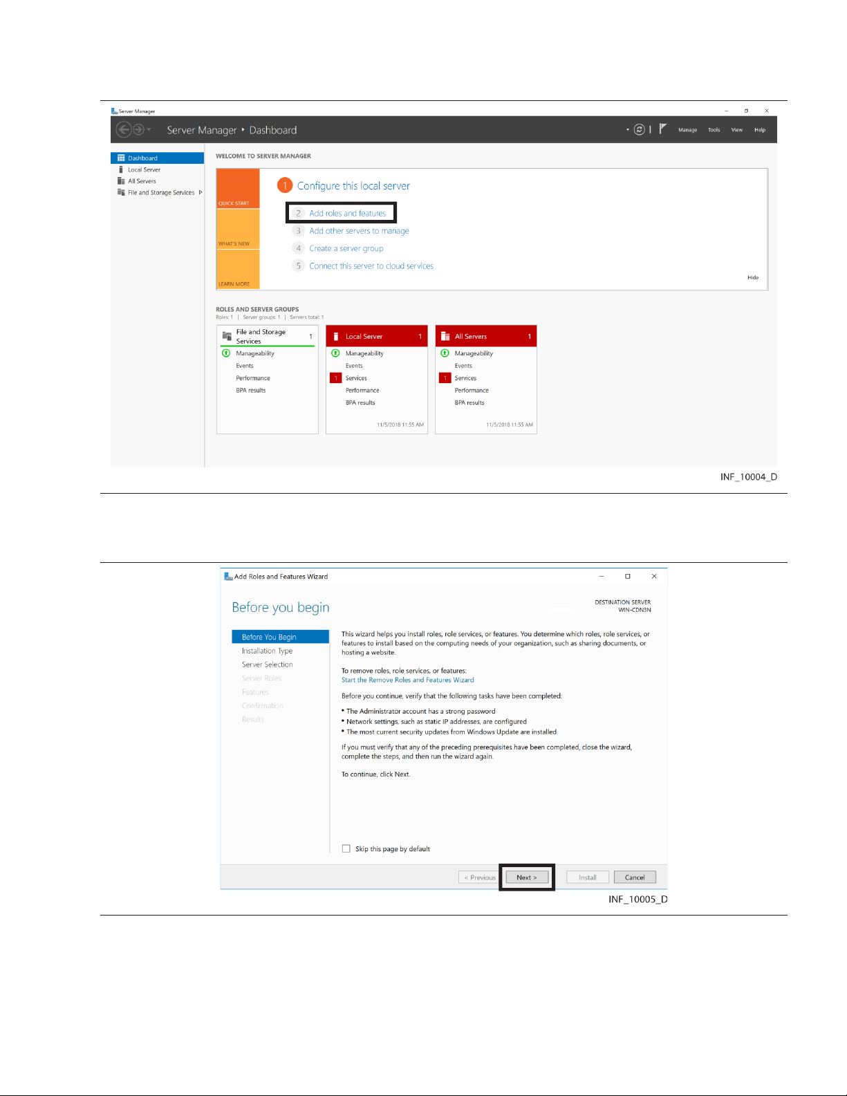
2. Open the Server Manager. Figure 1. Server Manager
3. In the Dashboard pane, click on Add Roles and Features to start the Add Roles and Features
wizard.
Figure 2. IIS Add Roles and Features Wizard—Start Page
4. Verify that tasks listed on the page have been completed, then click Next to access the Installation
Type page.
22
Page 23
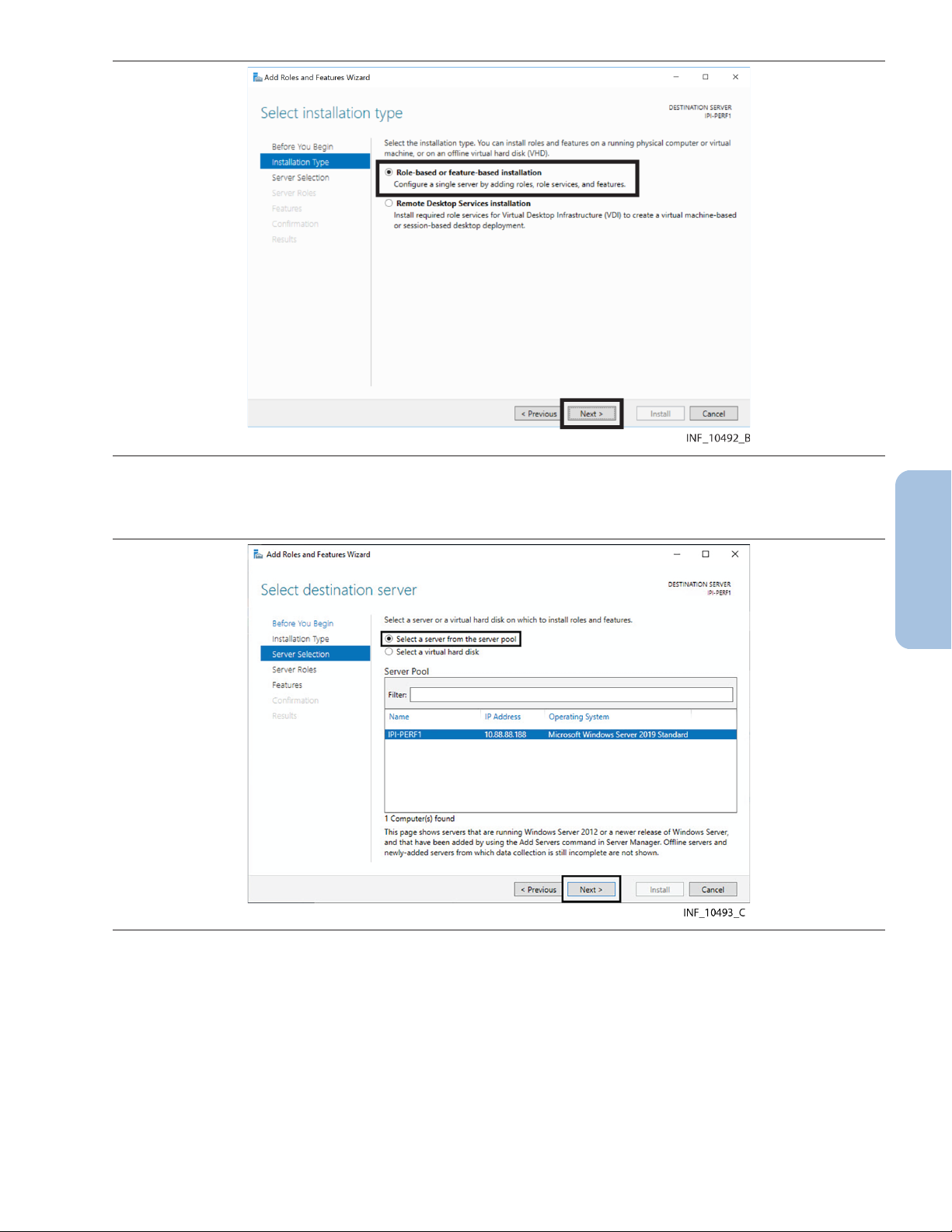
Figure 3. IIS Add Roles and Features Wizard—Installation Type Page
5. Click the Role-based or feature-based installation radio button if it is not already selected.
6. Click Next to access the Destination Server Selection page. Figure 4. IIS Add Roles and Features Wizard—Destination Server Selection Page
7. Click the Select a server from the server pool radio button if it is not already selected.
8. In the Server Pool pane, find the desired server and click on it to select it.
9. Click Next to access the Select Server Roles page.
23
Page 24
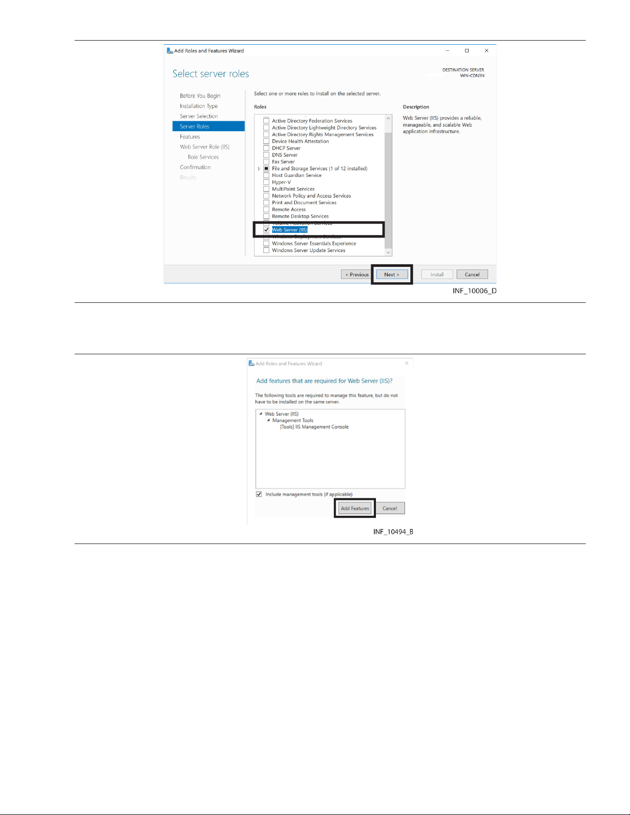
Figure 5. IIS Add Roles and Features Wizard—Select Server Roles Page
10. Check the Web Server (IIS) check box, then click Next to access the Add Required Features
page.
Figure 6. IIS Add Roles and Features Wizard—Add Required Features Page
11. Ensure that the Include management tools check box is checked, then click Add Features to
access the Select Features page.
24
Page 25
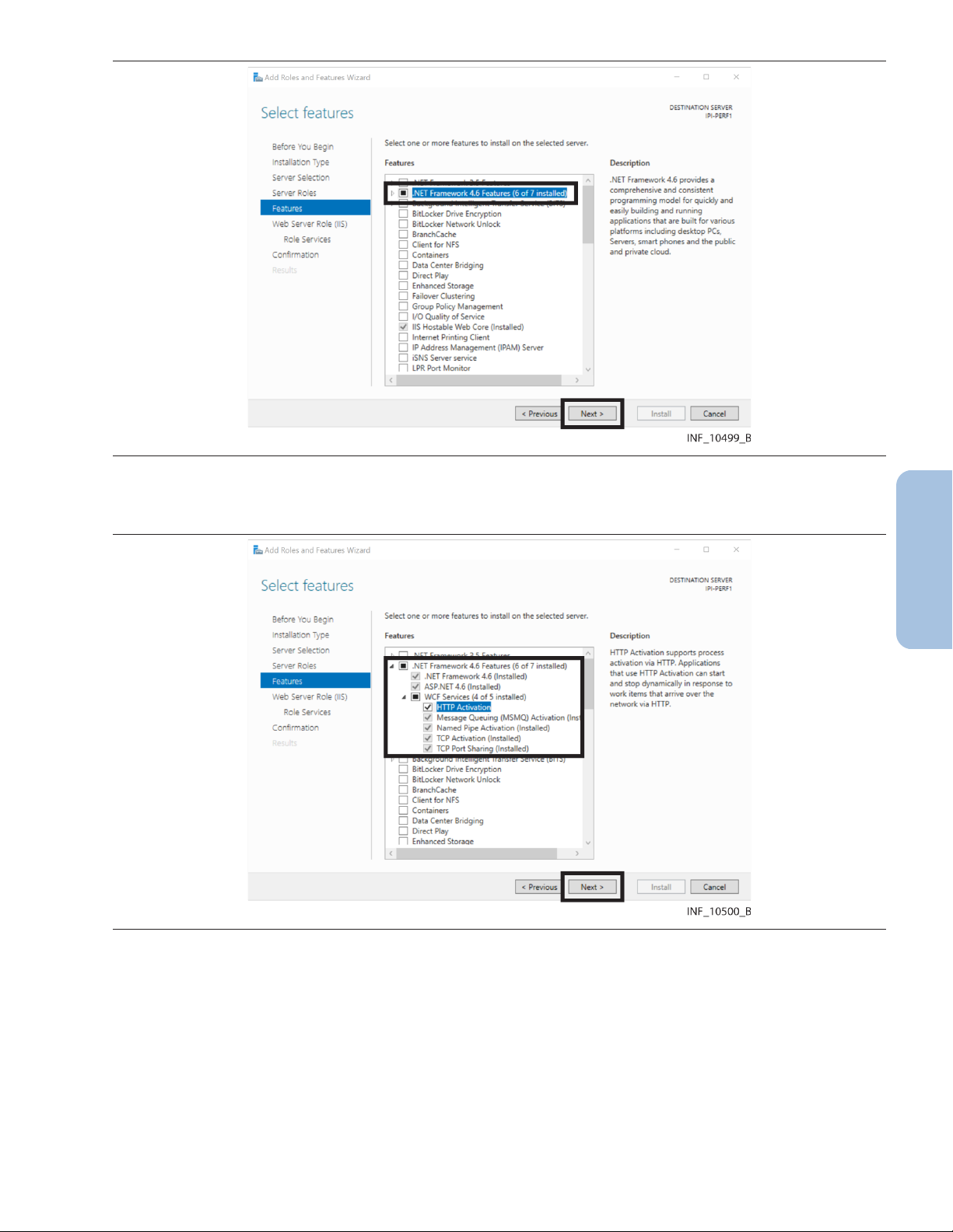
Figure 7. IIS Add Roles and Features Wizard—Select Features Page
12. Click the triangle next to the .NET Framework 4.6 Features check box to show available options
Figure 8. IIS Add Roles and Features Wizard—Select Features Page (.NET Framework 4.6 fields
shown)
13. Click the triangle next to the WCF Services check box to show available options.
14. Make selections as shown in Figure 8, then click Next to access the Web Server Role (IIS) page.
25
Page 26
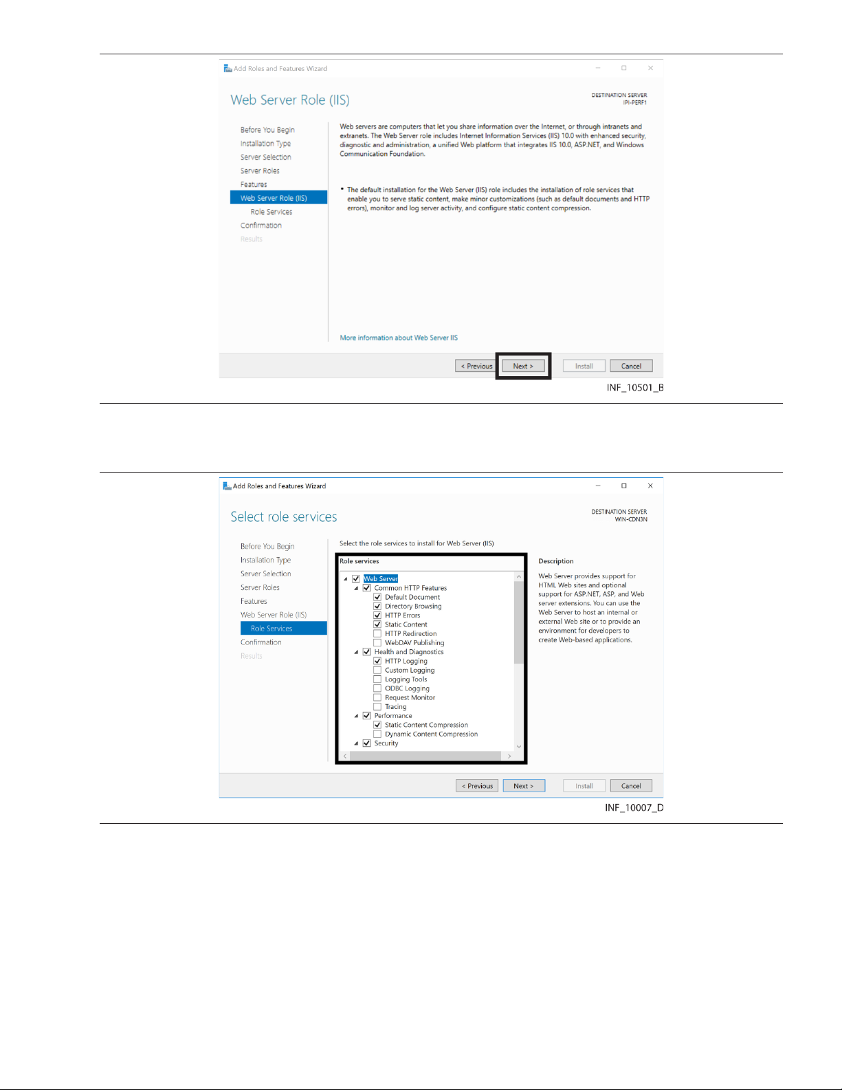
Figure 9. IIS Add Roles and Features Wizard—Web Server Role (IIS) Page
15. If needed, review the text on the page, then click Next to access the Select Role Services page.
Figure 10. IIS Add Roles and Features Wizard—Select Role Services Page (common HTTP and
health/diagnostics options)
16. Make selections in the role services fields as shown in Figure 10, then scroll down in the pane.
26
Page 27
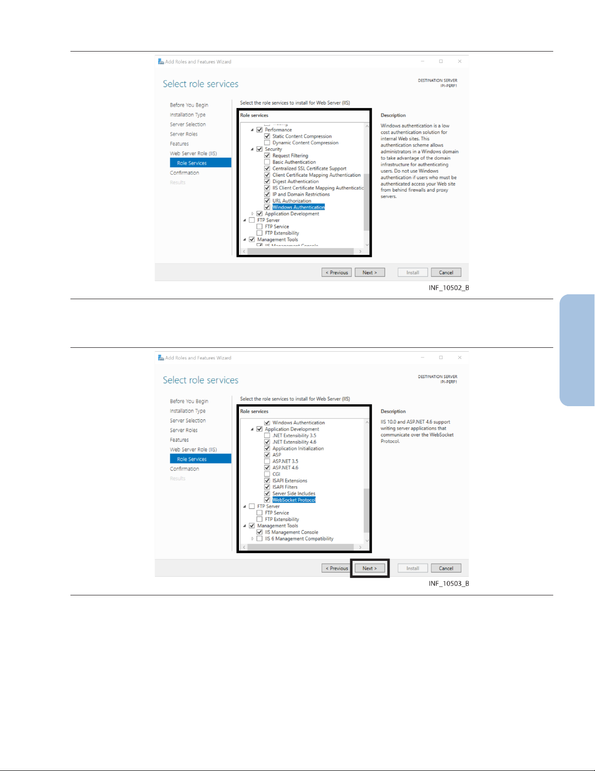
Figure 11. IIS Add Roles and Features Wizard—Select Role Services Page (performance and security options)
17. Make selections in the role services fields as shown in Figure 11, then scroll down in the pane.
Figure 12. IIS Add Roles and Features Wizard—Select Role Services Page (application
development options)
18. Make additional selections in the role services fields as shown in Figure 12, page 27, then click
Next to access the confirmation page.
27
Page 28
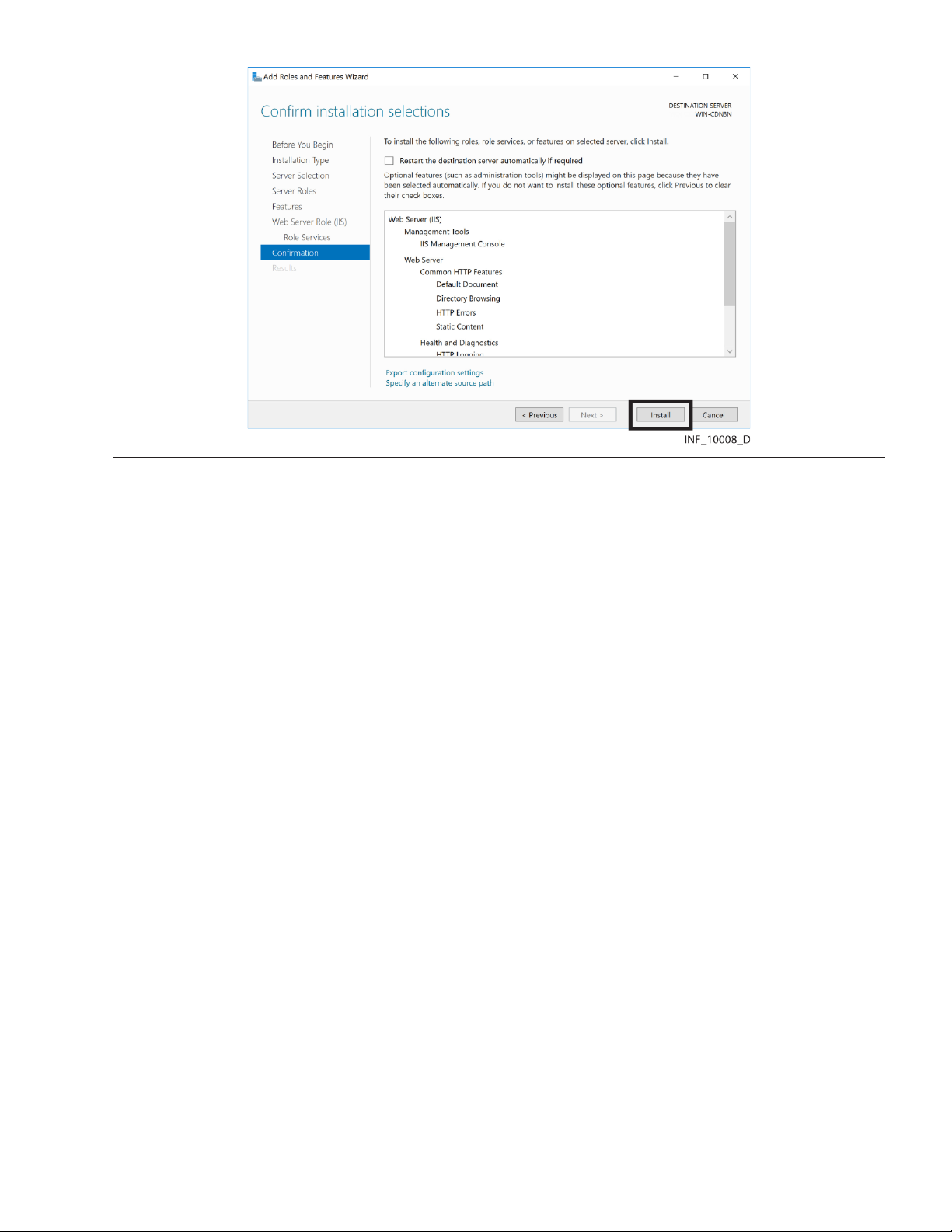
Figure 13. IIS Add Roles and Features Wizard—Confirmation Page
19. If desired, scroll down to view installation selections, then click Install. (Click Cancel to stop
installation.)
20. The results screen indicates whether the installation was successful, and lists role services
installed. If desired, click the Print, e-mail, or save link to print, email or save the installation
report, then click Close to exit the wizard.
Note: If installation is unsuccessful, problems that occurred will be shown in the results screen. Resolve
the problems and repeat the procedure for adding IIS role services before continuing with the other
procedures in this chapter.
3.4 Install Message Queuing
After adding IIS role services, add the Microsoft™* Message Queuing feature. For details on
installation, reference the technical document Installing and Managing Message Queuing, available
online at the following URL:
https://docs.microsoft.com/en-us/previous-versions/windows/it-pro/windows-server-2008-R2-and-20
08/cc771474(v=ws.11)
• Note: Installing message queuing is only necessary if configuring the Vital Sync Alarms Reporter
Service. See Section 6.4.3, MSMQ Queue Configuration, page 99 for details.
• Note: Install message queuing on the same systems where IIS role services were just added. (Refer
to Section 5.6, Distributed Deployment, page 83 for details on installation in a distributed
environment.)
• Note: Install the Data Collection, Alarm Reporter, and Applet Manager services on the system
where MSMQ is configured.
• Note: Configure MSMQ per active directory user account. It is possible to configure and limit the
Data Collection, Applet Manager, and Alarm Reporter services with a Microsoft™* Windows™*
domains account with permissions for the MSMQ system. The Data Collection and Applet Manager
services should have write permissions; the Alarm Reporter service should have read permission.
28
Page 29
3.5 Configure IIS to Use HTTPS
After adding IIS role services, configure IIS to use HTTPS. For details, reference the technical document
How To Set Up an HTTPS Service in IIS, available online at the following URL:
https://support.microsoft.com/en-us/help/324069/how-to-set-up-an-https-service-in-iis
Other configuration to enable use of HTTPS and SSL is also required. See Section 5.5.
3.6 Configure the IIS Application Pool
After adding IIS role services, update the default Microsoft™* Windows™* Server Internet Information
Services (IIS) application pool to ensure that the Informatics Web component (when installed) will have
appropriate authority to run reports.
Note: Configure the IIS application pool on the same systems where IIS role services are installed.
Note: This manual shows screen captures for application pool configuration using version 10.0 of IIS.
Version 8.0 of IIS is also supported. The procedure does not differ significantly between the two
versions. If encountering problems during or after configuration, contact the Medtronic Solution
Delivery Team.
To configure the IIS application pool:
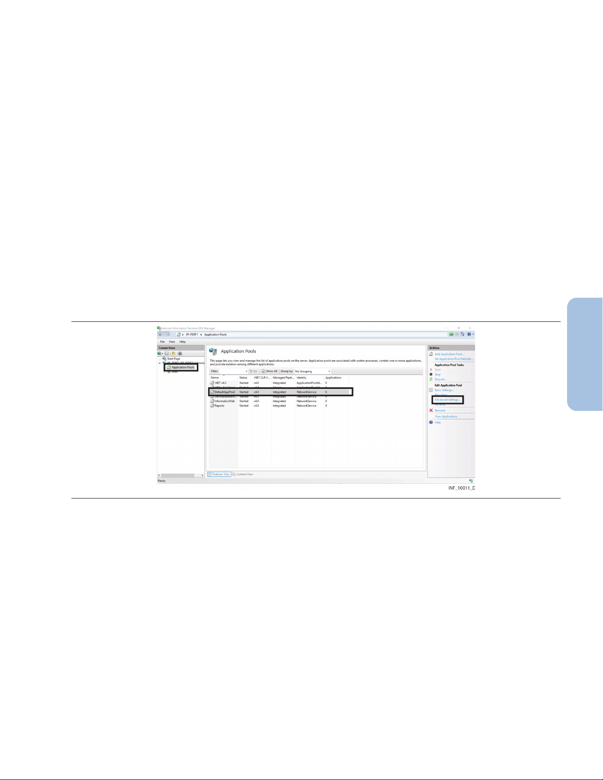
1. Open the IIS Manager. Figure 14. Internet Information Services (IIS) Manager (application pools shown)
2. Click Application Pools in the far left pane.
3. Click on DefaultAppPool to select it, then click Advanced Settings under Edit Application
Pool in the far right pane to open the Advanced Settings dialog.
29
Page 30
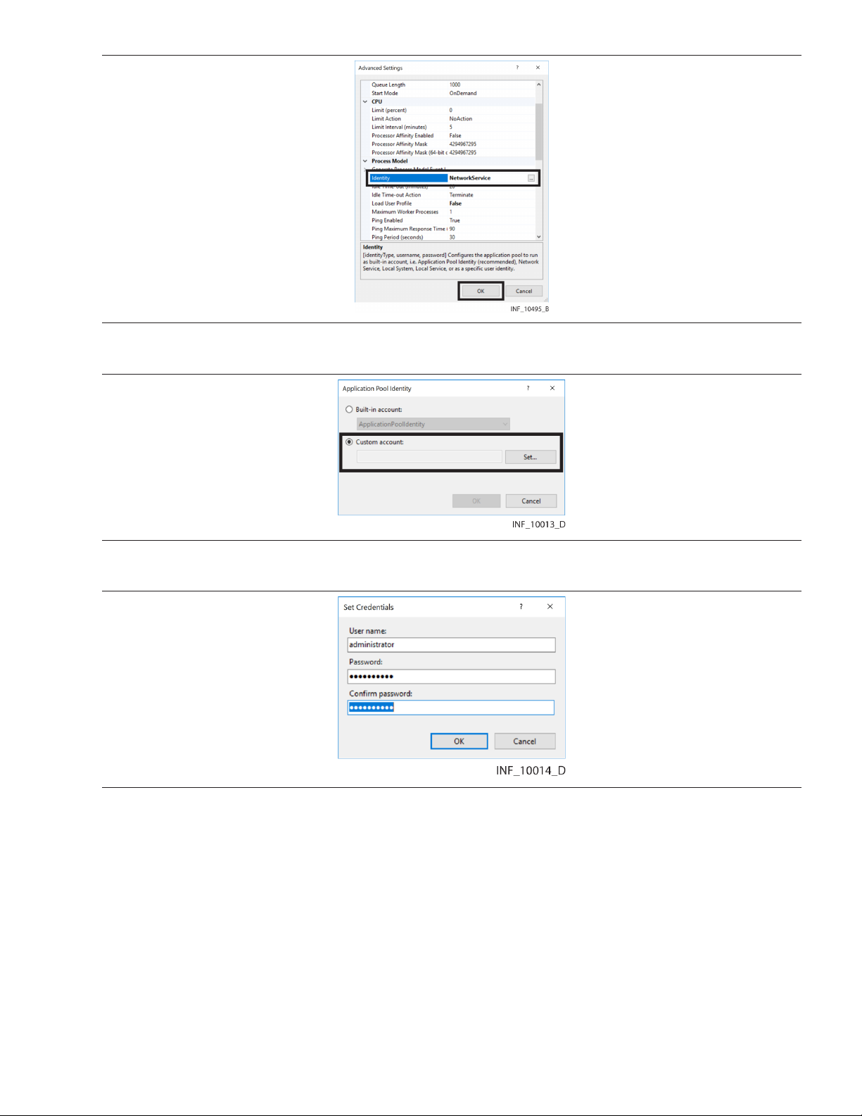
Figure 15. Edit Application Pools (Advanced Settings dialog)
4. In the Identity field, click the ... button to open the Application Pool Identity dialog. Figure 16. Application Pool Identity Dialog
5. Click the Custom account radio button, then click Set to open the Set Credentials dialog. Figure 17. Set Credentials Dialog
6. User name—Enter the user name for an appropriate administrative user with authority to run
reports. Often, the same user will also be set up as the administrator when Microsoft™* SQL
Server™* is installed. Refer to Section 3.7, Install the Database Server, page 31.
7. Password—Enter the password for the specified administrative user.
8. Confirm password—Enter the password just entered in the Password field.
9. Click OK to save and return to the Application Pool Identity dialog.
10. Click OK to save application pool identity settings and return to the Advanced Settings dialog.
11. Click OK to save advanced settings for the default application pool and return to the IIS Manager.
12. Exit the IIS Manager.
30
Page 31

3.7 Install the Database Server
After configuring the IIS application pool, install and configure the database server software.
The installation wizard shows a series of screens for selection of application options. If needing to
change a selection already made, click Back to go back to the previous screen, then make the change.
In any screen, if needed, click Cancel to stop the installation and exit the wizard.
Note: Install the database server software on the system where the Database component is to be
installed. If using a distributed deployment with separate Online Transaction Processing (OLTP) and
Data Warehouse systems, install the database server software on both systems.
To access the installation program:
1. Find and right-click on the icon for the computer on the desktop, then click Explore, or navigate to
the computer in Windows Explorer™*.
2. Double-click on the directory containing the installation files to open the directory.
3. Find Setup.exe.
Note: Refer to Section 5.6, Distributed Deployment, page 83 for details on additional installation and
setup steps for distributing database operations across multiple systems.
Note: This manual shows the installer for Microsoft™* SQL Server™* 2019. Microsoft™* SQL
Server™* 2016 is also supported. The installation procedure for Microsoft™* SQL Server™* 2016
does not differ significantly; refer to its installation documentation for more detailed information. If
encountering problems during or after installing Microsoft™* SQL Server™*, contact the Medtronic
Solution Delivery Team.
To install Microsoft™* SQL Server™*:
1. Double-click Setup.exe to run the installer.
2. If a user account control dialog appears asking for confirmation that changes should be made to
this computer, click Yes to continue. The Installation Center screen will appear.
3. Click Installation in the left panel to show available installation options.
31
Page 32

Figure 18. Microsoft™* SQL Server™* Installation Center
4. Click New SQL Server stand-alone installation or add features to an existing installation
to open the setup wizard and access the Product Key page.
Figure 19. Microsoft™* SQL Server™* Setup Wizard—Product Key
5. Click the Enter the product key radio button to access the product key field, then (if needed)
enter the 25-character product key provided with Microsoft™* SQL Server™*. Click Next to
proceed to the License Terms page.
Note: If the software was downloaded directly from the manufacturer, the product key may
automatically appear on this page.
32
Page 33

Figure 20. Microsoft™* SQL Server™* Setup Wizard—License Terms
6. End-user license agreement (EULA) terms are shown in the License Terms page. If desired, click
Copy to copy the EULA text to the clipboard; click Print to print the EULA.
7. To continue with the installation, click the I accept the license terms check box (and the Send
feature usage data check box if desired), then click Next to proceed.
8. The installer will check for problems that could arise from installing support files.
If problems are found, a screen will appear allowing review of items checked. Click Show Details
to view the list; click Hide Details to hide the list. Resolve any problems found, then click Re-run.
Note: Users must resolve the underlying cause of any operation indicated as having failed before
the installation can proceed. Users should check the underlying cause of any operation indicated
as having a warning, but operations with warnings do not prevent the installation from continuing.
If no problems are found, the Microsoft™* Update page will appear.
33
Page 34

Figure 21. Microsoft™* SQL Server™* Setup Wizard—Microsoft™* Update
9. If needed, click in the Use Microsoft Update to check for updates box to check it, then click
Next. The installer will check for updates, and will automatically download and extract the updates
if any are available.
10. When the update check is complete, the wizard will proceed to the Product Updates page. If
updates are available, a list of the updates downloaded appears on the screen, including links to
a document showing more information about each update. If no updates are currently available,
a message indicating this will appear. In either case, click Next to proceed to the Install Setup Files
page.
Figure 22. Microsoft™* SQL Server™* Setup Wizard—Install Setup Files (details shown)
11. The installer will automatically install setup files. The status of this operation and the product
update operations are shown in the middle of the page.
34
Page 35

12. When finished installing setup files, the wizard will proceed to the Install Rules screen and will
automatically check for problems that could arise from installing support files. A progress bar
shows the level of completion of the check.
Figure 23. Microsoft™* SQL Server™* Setup Wizard—Install Rules
Click Show Details to view a list of items checked; click Hide Details to hide the list. If the check
indicates problems, resolve them, then click Re-run.
Note: Users must resolve the underlying cause of any operation indicated as having failed before
the installation can proceed. Users should check the underlying cause of any operation indicated
as having a warning, but operations with warnings do not prevent the installation from continuing.
13. After resolving any problems, or if no problems occur, click Next to proceed to the Feature
Selection page.
35
Page 36

Figure 24. Microsoft™* SQL Server™* Setup Wizard—Feature Selection
14. Make selections in the Instance Features and Shared Features check boxes as shown, then
click Next to proceed to the Feature Rules page.
Figure 25. Microsoft™* SQL Server™* Setup Wizard—Feature Rules
Note: If installing database components on a machine without SQL command, a dialog will
appear indicating that Microsoft™* Command Line Utilities for SQL Server (also known as the
SQLCMD utility) is required. Install the most current version of this software before proceeding
with installation of database components.
36
Page 37

15. The installer will again check for problems that could interfere with installation. A progress bar
shows the level of completion of the check. Click Show Details to view a list of items checked;
click Hide Details to hide the list.
If the check indicates problems, resolve them, then click Re-run.
Note: Users must resolve the underlying cause of any operation indicated as having failed before
the installation can proceed. Users should check the underlying cause of any operation indicated
as having a warning, but operations with warnings do not prevent the installation from continuing.
16. After resolving any problems, click Next to proceed to the Instance Configuration page. Figure 26. Microsoft™* SQL Server™* Setup Wizard—Instance Configuration
17. If no SQL server instances exist on the system, click the Default Instance radio button.
Otherwise, click the Named Instance radio button and enter a name for the new instance. When
ready to continue, click Next to proceed to the Server Configuration page.
37
Page 38

Figure 27. Microsoft™* SQL Server™* Setup Wizard—Server Configuration
18. On the Service Accounts tab, ensure NT Service\SQLSERVERAGENT appears in the Account
Name column for SQL Server Agent, and NT Service\MSSQLSERVER appears in the Account
Name column for SQL Server Database Engine.
19. In the Startup Type column, make selections from the appropriate drop-down boxes as shown in
Figure 27.
20. Click Next to proceed to the Database Engine Configuration page. Figure 28. Microsoft™* SQL Server™* Setup Wizard—Database Engine Configuration
21. On the Account Provisioning tab, in the Authentication Mode area, click the Mixed mode radio
button.
22. Enter the desired authentication password in the Enter password and Confirm password
fields.
38
Page 39

23. Below the Specify SQL Server Administrators pane, click Add Current User to add the current
user as an administrator for this SQL server instance. The username of the current user will appear
in the pane.
Figure 29. Microsoft™* SQL Server™* Setup Wizard—Database Engine Configuration (administrator added)
24. Click Next to proceed to the Feature Configuration Rules page. Figure 30. Microsoft™* SQL Server™* Setup Wizard—Feature Configuration Rules
25. The installer will once again check for any problems that could interfere with installation. A
progress bar shows the level of completion of the check. Click Show Details to view a list of items
checked; click Hide Details to hide the list.
If the check indicates problems, resolve them, then click Re-run.
39
Page 40

Note: Users must resolve the underlying cause of any operation indicated as having failed before
the installation can proceed. Users should check the underlying cause of any operation indicated
as having a warning, but operations with warnings do not prevent the installation from continuing.
26. After resolving any problems, click Next to proceed to the Ready to Install page. Figure 31. Microsoft™* SQL Server™* Setup Wizard—Ready to Install
27. The Ready to Install page shows all software components to be installed on the destination
machine. Review the list if desired, then click Install.
28. Once the installer has finished, the finish page will appear.
Figure 32. Microsoft™* SQL Server™* Setup Wizard—Finish
Note: If no problems occurred during installation, a message indicating successful installation
(denoted by a green check mark) will appear. If any problem occurred, a descriptive message
(denoted by a red octagon) will appear.
40
Page 41

29. After reviewing installation information, click Close to exit the installation wizard. (If problems
occurred during installation, resolve them, then repeat this procedure until installation is
successful.)
Note: The remainder of this procedure assumes that Microsoft™* SQL Server™* Management
Studio is installed. If that application is not present, install it before continuing.
30. In the Object Explorer in Microsoft™* SQL Server™* Management Studio, find the SQL database
server just installed.
Figure 33. Microsoft™* SQL Server™* Management Studio Object Explorer (server context menu)
31. Right-click on the server name to open a context menu, then select Properties to open the
Properties dialog box.
32. Click on Memory to show the Memory options page.
41
Page 42

Figure 34. Database Server Properties Dialog (Memory page)
33. Set the Minimum server memory value to 5000, and set the Maximum server memory value
to 10000.
34. Click OK to exit the dialog.
35. Restart the system before continuing with the additional application installation and configuration
procedures detailed in this manual.
3.8 Distributor Configuration
After installing the database server software, configure the database server as a distributor to enable
and support replication.
The configuration wizard shows a series of screens for selection of application options. If changes are
required to selections already made, click Back to go back to the previous screen, then make the
change.
In any screen, if needed, click Cancel to stop configuration and exit the wizard.
• Note: The default configuration selections indicated here are recommended. If different selections
are required, consult with the Medtronic Solution Delivery Team.
• Note: The procedure shown in this section assumes that Microsoft™* SQL Server™* 2019 is
installed. If Microsoft™* SQL Server™* 2016 is installed, the procedure does not differ significantly.
If encountering problems, consult with the Medtronic Solution Delivery Team.
• Note: Server names shown in this section are for illustrative purposes only; actual server names will
vary.
To configure the database server as a distributor:
1. In the Object Explorer in Microsoft™* SQL Server™* Management Studio, find the SQL database
server installed for use with the Vital Sync software.
42
Page 43

Figure 35. Microsoft™* SQL Server™* Management Studio (Replication folder context menu)
2. Right-click on the Replication folder icon to open a context menu, then select Configure
Distribution to launch the Configure Distribution wizard. Figure 36. Configure Distribution Wizard—Start
3. Click Next to proceed to the Distributor page.
43
Page 44

Figure 37. Configure Distribution Wizard—Distributor
4. Make sure the top radio button (indicating that this server will act as its own distributor) is selected,
then click Next to proceed to the SQL Snapshot Folder page.
Figure 38. Configure Distribution Wizard—Snapshot Folder
5. Click Next to accept the default path for the snapshot folder and proceed to the Distribution
Database page.
44
Page 45

Figure 39. Configure Distribution Wizard—Distribution Database
6. Click Next to accept the default distribution database name and default paths for the database
and database log files, and proceed to the Publishers page.
Figure 40. Configure Distribution Wizard—Publishers
7. Make sure the check box next to the database just installed is checked, then click Next to proceed
to the Wizard Actions page.
45
Page 46

Figure 41. Configure Distribution Wizard—Wizard Actions
8. Make sure the Configure distribution check box is checked, then click Next to proceed. Figure 42. Configure Distribution Wizard—Complete
9. Review selections, then click Finish to configure distribution.
46
Page 47

Figure 43. Configure Distribution Wizard—Finish
10. A screen indicating progress will appear; green check marks indicate success of each operation.
If any problems occur during configuration, click Report to view details, then resolve any issues
and rerun the wizard.
11. If no problems occur, or once problems are resolved and rerunning the wizard indicates success
for all configuration operations, click Close to exit the wizard.
Note: If configuration is unsuccessful, it is possible the SQL Server Agent is not set to automatically
launch. Check the status of the SQL Server Agent in the SQL Server Configuration Manager; ensure
that the agent is running and set to Automatic. Refer to Section 3.9, Enable Remote Connection,
page 48 for access details.
On completion of distributor configuration, a new database icon will be visible in the System Databases
list in the Microsoft™* SQL Server™* Management Studio Object Explorer. This icon will have the name
selected in the distribution database setup screen (refer to Step 6 of this procedure).
47
Page 48

Figure 44. Microsoft™* SQL Server™* Management Studio Object Explorer (new database shown)
3.9 Enable Remote Connection
After installing all supporting software and application components, adjust the database configuration
to enable remote users to connect to the database.
Note: Only perform the steps listed in this section if application components are installed on multiple
systems. If using a distributed deployment with separate Online Transaction Processing (OLTP) and
Data Warehouse systems, perform the steps in this section on both systems.
Note: The procedure shown in this section assumes that Microsoft™* SQL Server™* 2019 is installed.
If Microsoft™* SQL Server™* 2016 is installed, the procedure does not differ significantly. If
encountering problems, consult with the Medtronic Solution Delivery Team.
To enable remote connection:
1. Launch the SQL Server Configuration Manager.
2. In the left pane, click on SQL Server Services.
3. Right-click on SQL Server Browser (listed in the right pane) to open a context menu.
48
Page 49

Figure 45. Microsoft™* SQL Server™* Configuration Manager—SQL Server Browser Context Menu
4. Select Properties to open the Properties dialog.
Figure 46. Microsoft™* SQL Server™* Configuration Manager—SQL Server Browser
Properties Dialog
5. Click on the Service tab to access it.
6. Click on the drop-down box next to Start Mode and select Automatic.
49
Page 50

7. Click OK to exit the Properties window and return to the SQL Server Configuration Manager
window. In the right pane, the value in the State column for the SQL Server Browser should be
Running.
8. In the left pane, click on the triangle next to the SQL Server Network Configuration icon to
expand the directory, then click on Protocols for MSSQLSERVER (or the server and instance
name selected for the database during installation, if different) to show protocols in the right pane.
9. Check the value in the Status column in the right pane for the TCP/IP protocol. If not set to
Enabled, right-click on TCP/IP to open a context menu.
10. Select Properties to open the Properties dialog. Figure 47. Microsoft™* SQL Server™* Configuration Manager—TCP/IP Properties Dialog
11. Click on the drop-down box next to Enabled and select Yes.
12. Click OK to return to the SQL Server Configuration Manager window.
13. Check the value in the Status column in the right pane for the Named Pipes protocol. If not set to
Enabled, right-click on Named Pipes to open a context menu.
14. Select Properties to open the Properties dialog.
50
Page 51

Figure 48. Microsoft™* SQL Server™* Configuration Manager—Named Pipes Properties Dialog
15. Click on the drop-down box next to Enabled and select Yes.
16. Click OK to return to the SQL Server Configuration Manager window.
17. In the left pane, if needed, click to the left of the SQL Native Client 11.0 Configuration (32bit)
icon to expand the directory, then click on Client Protocols to show protocols in the right pane.
Figure 49. Microsoft™* SQL Server™* Configuration Manager—Native Client 11.0 (32-Bit) Client Protocols
18. Ensure the value in the Enabled column both for TCP/IP and for Named Pipes is Enabled. If not,
apply Step 9 through Step 15 of this procedure as needed to change affected items.
51
Page 52

19. A warning dialog will appear indicating that the client protocol changes will be saved, but will not
take effect until affected services are restarted. Click OK to save changes and return to the SQL
Services Configuration Manager window.
20. In the left pane, if needed, click to the left of the SQL Native Client 11.0 Configuration icon to
expand the directory, then click on Client Protocols to show protocols in the right pane.
Figure 50. Microsoft™* SQL Server™* Configuration Manager—Native Client 11.0 Client Protocols
21. Ensure the value in the Enabled column both for TCP/IP and for Named Pipes is Enabled. If not,
apply Step 9 through Step 15 of this procedure as needed to change affected items.
22. A warning dialog will appear indicating that the client protocol changes will be saved, but will not
take effect until affected services are restarted. Click OK to save changes and return to the SQL
Services Configuration Manager window.
23. In the left pane, click on SQL Server Services.
24. In the right pane, the value in the State column for the SQL Server Browser should be Stopped.
Right-click on SQL Server Browser to open a context menu.
Figure 51. Microsoft™* SQL Server™* Configuration Manager—SQL Server Browser Start
25. Select Start to start the SQL Server Browser running.
26. Right-click on SQL Server (MSSQLSERVER) (or the server and instance name selected during
installation, if different) to open a context menu.
52
Page 53

Figure 52. Microsoft™* SQL Server™* Configuration Manager—SQL Server Restart
27. Select Restart to restart the SQL server service, with the configuration changes made.
28. Right-click on SQL Server Agent (MSSQLSERVER) (or the server and instance name selected
for the database during installation, if different) to open a context menu.
Figure 53. Microsoft™* SQL Server™* Configuration Manager—SQL Server Agent Restart
29. Select Restart to restart the SQL server agent, with the configuration changes made.
53
Page 54

54
Page 55

4 Installing Software Components
4.1 Overview
This chapter provides information on installation of components of the Vital Sync virtual patient
monitoring platform and informatics manager software.
• Note: While all components can be installed on a single system, Medtronic recommends
that the Informatics Web and Database components should be installed on separate
systems, especially if a large number of users will access and use the software, or if a large number
of patients and devices will be connected and monitored. Reference hardware and software
configurations in Chapter 2, or consult with the Medtronic Solution Delivery Team or with facility IT
personnel for more information.
• Note: If upgrading from a previous version, make backups of all database files before installing the
current version of the software.
• Note: If upgrading from a version of the software previous to v2.5.x, uninstall the older version
before installing the current version. Consult the Medtronic Solution Delivery Team for more
information.
• Note: If upgrading from v2.5.x, to avoid potential database problems, first upgrade to v2.6.4, then
upgrade to v3.0.0.
4.2 Installation
All components are included in the Vital Sync software installation package, received from the
Medtronic Solution Delivery Team.
Note: To install software, administrative rights are required on destination systems.
• Section 4.2.1, Component Constraints
• Section 4.2.2, Security Considerations • Section 4.2.4, Component Installation
4.2.1 Component Constraints
Certain components must be installed on specific systems, based on the supporting software installed
on those systems.
• Install the Database component on a system where Microsoft™* SQL Server™* is already
installed.
• Install the Data Collection Service, Applet Manager Service (if used), Reports, and Informatics Web
components on the same system where Microsoft™* Windows™* Server IIS role service and
application pool setup is already complete.
See Chapter 3 for more information on supporting software. See Chapter 5 for more information on
multi-system installation.
4.2.2 Security Considerations
• Section 4.2.3, Access
Note: See Section 2.5 for additional security recommendations, and implement these
recommendations as needed before installing the Vital Sync software.
To maximize security when using the Vital Sync software, do the following during and after installation:
• Once installation is complete and the software is deployed, delete the installer logs.
• If the installer and license file are present on any of the systems running the software, delete them
once the software is installed.
55
Page 56

• When setting the password for the default Vital Sync informatics manager administrative user, enter
a unique and strong password in place of the default password.
• Web API functionality should only be deployed if needed.
4.2.3 Access
To access the installer:
1. Find and right-click on the icon for the computer on the desktop, right-click on it, then click
Explore, or navigate to the computer in Windows™* Explorer™*.
2. Navigate to the location in the directory where the installation files reside.
3. Find informatics_setup.exe.
4.2.4 Component Installation
The installation wizard shows a series of screens for selection of software options. If needing to change
a selection already made, click Back to go back to the previous screen and make the change.
In any screen, if needed, click Cancel to stop the installation and exit the wizard.
To install components:
1. Double-click informatics_setup.exe to run the installer.
2. If a dialog appears asking for confirmation that changes should be made to this computer, click
Yes to continue.
3. If Microsoft™* .NET Framework 4.6.2 is not present on the system, the Requirements page will
appear. Click Install to install the missing software, entering administrative user credentials if
necessary to confirm the installation. (Click Cancel to exit the installation wizard.)
Note: The Microsoft™* Web Deploy utility is installed along with the Vital Sync software
components.
4. The system may need to be rebooted before continuing. If so, log onto the system after rebooting,
using the same credentials. The installation wizard should automatically start again; if not, restart
the wizard (see Section 4.2.3, Access, page 56).
5. Once all necessary supporting software is installed on the system, the Welcome page will appear.
56
Page 57

Figure 54. Informatics Installation Wizard—Welcome Page
6. Click Next to proceed to the Feature License Information page. Figure 55. Informatics Installation Wizard—Feature License Information Page
7. Serial Number—Enter the license key received from the Medtronic Solution Delivery Team.
8. License File—Enter the filename of the license file received from Medtronic, or click Browse...
and navigate to the directory where the license file resides. The license file has a .lic file extension,
and will typically have the license key as its filename.
Note: The license file is provided directly by the Medtronic Solution Delivery Team, separately
from the other installation files.
9. Click Next to proceed to the Destination Location page.
57
Page 58

Figure 56. Informatics Installation Wizard—Destination Location Page
10. The Destination Location page shows the default destination location for installation of software
components. If the components should be installed in a different location, click Browse and
navigate to the desired location. When finished, or if accepting the default location, click Next to
proceed to the Select Features page.
Figure 57. Informatics Installation Wizard—Select Features Page
11. The Select Features page shows available applications, as well as the amount of disk space
required to install selected components (currently selected components are denoted by checked
boxes). Click on any component listed to show a brief description of that component in the
Description pane.
58
Page 59

Note: If installing on multiple systems, some components must be installed on specific systems.
See Section 4.2.1, Component Constraints, page 55 and Section 5.6, Distributed Deployment,
page 83.
Note: Depending on the licensing status of components in the installation package, not all
screens shown in this procedure description may appear. For details on licensing of individual
components, consult with Medtronic.
12. Click in check boxes to check or uncheck them until all components to be installed are selected
(indicated by a checked box).
Note: If a component is not currently licensed, its check box will be unchecked when this page first
appears. The description will still appear when clicking an unlicensed component, but will indicate
that the component is unlicensed; the component’s check box for selection will be unavailable.
Note: The Nurse Station Client component and the Bedside Station Client component cannot be
installed simultaneously. If installing either of these components, make sure the check box for the
other component is unchecked before proceeding.
13. Click Next to proceed to the Language Options page. Figure 58. Informatics Installation Wizard—Language Options Page
14. English is the only language available to be shown in the software user interface, and is already
selected. Click Next to proceed to the Administrator Password page.
59
Page 60

Figure 59. Informatics Installation Wizard—Administrator Password Page
15. Password—Accept the default value, or enter a password conforming to facility guidelines.
Note: Medtronic recommends changing from the default to use a strong password (8 to 32
characters long, including at least one uppercase and one lowercase letter and one number, with
special characters also permissible).
16. Confirm—Accept the default value, or enter the password entered in the Password field again.
17. Click Next to proceed.
18. If creating an account for a central nurse station (as chosen in Step 12), the Nurse Station Account
Creation page will appear. (If not creating this account, skip to Step 25. If not creating a central
nurse station account or a bedside display user account, the Failover Log File page will appear;
skip to Step 34.)
60
Page 61

Figure 60. Informatics Installation Wizard—Nurse Station Account Creation Page
19. Account User Name—Enter the username of the nurse station account (this can be the name of
the nurse station at which the platform is to be used).
20. Display Name—Enter the display name for the nurse station. (This name will appear on the user
function button in the platform user interface.)
Note: The display name should be as short as is practical; space on the user function button is
limited.
21. Device Data Service Location—Enter the host name or IP address for the system on which the
Device Data Service component is to be installed.
22. Vital Sync Web Server Location—Enter the host name or IP address for the system on which
the Vital Sync Web Server component is to be installed.
23. Overwrite User—Accept the default value (unchecked) to create a new account, or check the
box to overwrite an existing central nurse station account (also called a remote monitoring station
account in earlier releases of the software).
24. Click Next to proceed.
25. If creating an account for a bedside display user, the Bedside Monitoring Station Account Creation
page will appear. (If not creating this account, skip to Step 34.)
61
Page 62

Figure 61. Informatics Installation Wizard—Bedside Monitoring Station Account Creation Page
26. Bed Name—Enter the name of the bed at which the bedside display is to be used.
27. Bedside Account Name—Enter the name for the bedside account. (This name will appear in the
platform user interface.)
28. Device Data Service Location—Enter the hostname or IP address for the system on which the
Informatics Web component is to be installed.
29. Admin User—Accept the default value (administrator).
30. Admin Password—Accept the default value, or enter a password conforming to facility
guidelines.
Note: Medtronic recommends changing from the default to use a strong password (8 to 32
characters long, including at least one uppercase and one lowercase letter and one number, with
special characters also permissible).
31. Vital Sync Web Server Location—Enter the hostname or IP address for the system on which the
Informatics Web component is to be installed.
32. Overwrite User—Accept the default value (unchecked) to create a new account, or check the
box to overwrite an existing bedside monitoring station account.
33. Click Next to proceed to the Failover Log File page.
62
Page 63

Figure 62. Informatics Installation Wizard—Failover Log File Page
34. The default location for the failover log file (the file in which the software will record events if the
regular event log is inaccessible) is shown. If desired, enter an alternate directory path, or click
Browse and navigate to the desired directory. When finished, or if accepting the default location,
click Next to proceed.
35. If the selected destination folder for the failover log file does not exist, a dialog will appear asking
if the folder should be created. Click Yes to create the folder and proceed to the Primary
(Informatics) Database Information page, or click No to return to the failover log location screen to
select an existing folder, then click Next to proceed.
Figure 63. Informatics Installation Wizard—Primary (Informatics) Database Information Page
63
Page 64

36. Server—Enter the server name for the SQL server instance that will support primary clinical and
supervisory operations. (Use the server name selected during SQL server software installation on
the system where the SQL server instance that supports operations is installed. See Install the
Database Server, Step 17.
Note: If using distributed deployment, with a dedicated Online Transaction Processing (OLTP)
system supporting primary clinical and supervisory operations, enter information for the SQL
server instance on the OLTP system into the fields on the Operations Database Information page.
See Section 5.6, Distributed Deployment, page 83.
Note: Network configuration settings may require an IP address to be used instead of a server
name alone. If so, append the IP address after the server name, separating them with an @ sign
(for example, ServerName@xxx.xx.xx.xx). If needed, consult with facility IT personnel to obtain
the IP address of the system where the SQL server instance is installed.
37. Instance—If using the default instance, leave this field blank. If not using the default instance,
enter the instance name for the instance to be used.
38. Database File Location—If not using the default directory path, enter the desired directory path
for the database file.
39. Log File Location—If not using the default directory path, enter the desired directory path for the
log file.
Note: By default, Vital Sync databases use the Simple recovery model, under which the size of the
database log file is automatically managed. If using the Full recovery model, ensure a
maintenance plan is in place to cleanse database log files and manage file sizes.
40. When finished, click Next to proceed to the Primary (Informatics) logon information page. Figure 64. Informatics Installation Wizard—Primary (Informatics) Logon Information Page
41. User Name—Enter sa.
42. Password—Enter the password set up for the SQL server instance that will support primary
clinical and supervisory operations. See Install the Database Server (Step 22).
43. Click Next to proceed.
64
Page 65

44. If a primary operations database already exists on the system (for example, if an older version of
the software was previously installed), a dialog will appear, with a warning that the existing
database will be overwritten during installation.
Figure 65. Informatics Installation Wizard—Database Overwrite Warning Dialog
45. If backups already exist for the primary operations database file used with the earlier version of the
software, click Yes to proceed to the Replication (Informatics Data Warehouse) and DataMart
page. If not, click No to return to the previous screen, then click Cancel to exit the installation
wizard.
Figure 66. Informatics Installation Wizard—Replication (InformaticsDataWarehouse) and DataMart Page
(After creating a backup of the database file, reopen the installation wizard and repeat all previous
steps in this procedure, then click Yes in the dialog when it appears again to proceed with
installation.)
46. Server—Enter the server name for the SQL server instance that will support the Informatics Data
Warehouse and DataMart database.
Note: If using distributed deployment, with a dedicated Data Warehouse system supporting
reporting functions, enter information for the SQL server instance on the Data Warehouse system
into the fields on the Reporting Database Information page. See Section 5.6, Distributed
Deployment, page 83.
47. Instance—Enter the instance name for the desired SQL server instance, if needed.
48. Database Files Location—If not using the default directory path, enter the desired directory path
for the database file.
49. Log Files Location—If not using the default directory path, enter the desired directory path for
the log file.
65
Page 66

Note: By default, Vital Sync databases use the Simple recovery model, under which the size of the
database log file is automatically managed. If using the Full recovery model, ensure a
maintenance plan is in place to cleanse database log files and manage file sizes.
50. When finished, click Next to proceed. If using separate instances for primary clinical and
supervisory operations and for reporting functions, the Replication (Informatics Data Warehouse)
and DataMart logon information page will appear.
Figure 67. Informatics Installation Wizard—Replication (InformaticsDataWarehouse) and DataMart Logon Information Page
Note: If using the same instance for both primary operations and reporting functions, the
Reporting Logon Information page will not appear.
51. User Name—Enter sa.
52. Password—Enter the password set up for the SQL server instance that will support reporting
functions. See Install the Database Server (Step 22).
53. Click Next to proceed.
54. If a database for primary functions and/or reporting is already installed, but the installation
currently in progress is not an upgrade, a confirmation dialog will appear indicating that the
existing databases will be deleted when the new databases are created. Click OK to proceed to
the Enable Replication page, or click Cancel to exit the installation wizard if the existing databases
should be backed up before proceeding.
66
Page 67

Figure 68. Informatics Installation Wizard—Enable Replication Page
55. Enable Replication—To enable database replication, leave the box checked. To disable
replication, click in the box to uncheck it.
Note: If Enable Replication is checked, and distribution is enabled (see ||xref||), the installer will
remove the distribution database and any existing replications. If Enable Replication is not
checked, the installer will remove existing replications for the informatics database.
56. Click Next to proceed to the Distribution Database page. Figure 69. Informatics Installation Wizard—Distribution Database Page
57. Location—If not using the default directory path, enter the desired directory path for the
distribution database.
58. Click Next to proceed to the User Manual Location page.
67
Page 68

Figure 70. Informatics Installation Wizard—User Manual Location Page
59. Enter the directory path to the electronic version of this reference manual, or click Browse... and
navigate to the directory where the file resides. The reference manual file has a .pdf file extension.
Note: The directory path for the manual is provided by the Medtronic Solution Delivery Team at the
time of installation.
60. Click Next to proceed to the Report Server URL page. Figure 71. Informatics Installation Wizard—Report Server URL Page
61. URL—The default URL for the report server is shown. If desired, enter an alternate URL. When
finished, or if accepting the default location, enter the URL for the report server.
68
Page 69

Note: The report server URL is provided by the Medtronic Solution Delivery Team at the time of
installation.
62. Click Next to proceed.
63. If installing the Alarm Reporter to SMTP component (selected in Step 12), the Alarm Reporter
Email Settings page will appear. (If not installing this component, skip to Step 71.)
Figure 72. Informatics Installation Wizard—Alarm Reporter Email Settings Page
Note:
the Alarm Reporter to SMTP functionality. Obtain settings information for entry in the Alarm
Reporter Email Settings page from facility IT personnel.
64. SMTP URL—Enter the address for the email server from which system-generated email
messages sent to users of the platform should be sent.
65. SMTP Port—Enter the SMTP server port number to be used.
66. SMTP Username—Enter the appropriate username for the SMTP server.
67. SMTP Password—Enter the appropriate password for the SMTP server.
68. Return Address—Enter the address that will appear as the “From” address on email messages
sent to users of the platform.
69. SSL Enabled—Check the box to use Secure Socket Layer (SSL) communication with the email
server. (If not checked, messages sent to the email server will be treated as all other clear network
traffic.)
Note: For security purposes, Medtronic recommends activating this feature (checking the box). If
activated, the operating system should also be configured to use TLS 1.2.
70. Click Next to proceed.
71. If installing the Alarm Reporter to SMS component (selected in Step 12), the Alarm Reporter SMS
Settings page will appear. (If not installing this component, skip to Step 78.)
The facility must have existing email services from an appropriate provider in order to use
69
Page 70

Figure 73. Informatics Installation Wizard—Alarm Reporter SMS Settings Page
Note: The facility must have existing SMS messaging services from an appropriate provider in
order to use the Alarm Reporter to SMS functionality. Obtain settings information for entry in the
Alarm Reporter SMS Settings page from facility IT personnel.
72. User Name—Enter the user name for the SMS gateway via which system-generated SMS
messages sent to users of the platform should be sent.
73. Password—Enter the appropriate password for the SMS gateway.
74. From phone number—Enter the phone number that will appear as the “from” number on the
mobile device of the user receiving the SMS message.
75. Server URL—Enter the appropriate SMS gateway address.
76. Server Relative Path—Enter the appropriate path to the SMS gateway.
77. Click Next to proceed to the Installation Summary page.
70
Page 71

Figure 74. Informatics Installation Wizard—Installation Summary Page
78. If desired, review the list of components to be installed, as well as database configuration details.
When ready to continue, click Next.
79. If upgrading from a previously installed version of the software, a dialog showing version
information for the older installation will appear.
Figure 75. Informatics Installation Wizard—Previous Installation Dialog
Note: If upgrading from a version of the software previous to v2.5.x, exit the installation wizard and
uninstall the older version before installing the current version.
80. If backups already exist for all database files used with the previous version of the software, click
OK to proceed to the Confirmation page. If not, click Cancel to exit the installation wizard. After
creating backup database files, reopen the installation wizard and repeat all previous steps in this
procedure, then click OK in the dialog when it appears again to proceed with installation.
71
Page 72

Figure 76. Informatics Installation Wizard—Confirmation Page
81. If ready to install components, click Install. If not, click Back as needed to return to earlier pages
in the wizard, make any desired changes, then return to the Confirmation page and click Install.
82. A progress window (along with a series of command windows) will appear showing installation
progress. Once the installation is complete, a dialog will appear asking whether or not to start the
Data Collection Service.
Figure 77. Informatics Installation Wizard—Data Collection Service Start Dialog
83. If ready to start the Data Collection Service, click Yes. If not ready to start the Data Collection
Service, click No. (It is recommended to click No and manually start the service later once all
software installation is complete).
84. A progress window (along with a series of command windows) will appear showing installation
progress. Once the installation is complete, a dialog will appear asking whether or not to start the
Data Collection Service.
72
Page 73

Figure 78. Informatics Installation Wizard—Finish Page
85. Click Finish to exit the wizard.
86. Restart the system before continuing with the remaining configuration procedures detailed in this
manual.
Note: If installing components on multiple systems, repeat appropriate steps of the installation
procedure in this chapter for each component or set of components, until all required components have
been successfully installed on the appropriate systems.
73
Page 74

74
Page 75

5 Additional Configuration
5.1 Overview
This chapter provides information on final configuration steps before using the Vital Sync virtual patient
monitoring platform and informatics manager software.
Note: To install and configure software, administrative rights are required on destination systems.
Note: The procedures shown in this chapter assume that Microsoft™* SQL Server™* 2019 is installed.
If Microsoft™* SQL Server™* 2016 is installed, the procedures do not significantly differ. If
encountering problems during or after configuration, consult with the Medtronic Solution Delivery Team.
Note: Setup and configuration procedures in this chapter are to support the Vital Sync virtual patient
monitoring platform and informatics manager software.
• Section 5.2, Database Agent Startup
• Section 5.3, Firewall Configuration • Section 5.7, Data Warehouse Cleansing
• Section 5.4, Time Synchronization • Section 5.8, Applet Manager Configuration
• Section 5.5, HTTPS and SSL Configuration
• Section 5.6, Distributed Deployment
5.2 Database Agent Startup
Once the database server software and the software components are installed and configured, the
database server is ready for replication.
To fully enable replication, start the SQL Server and Snapshot agents.
Note: While performing the procedures in this chapter, have the name of the SQL database server
installed for use with the Vital Sync software readily available, to ensure the correct server is chosen.
5.2.1 SQL Server Agent
To start the SQL Server database agent:
1. In the Microsoft™* SQL Server™* Management Studio Object Explorer, find the SQL database
server installed for use with the Vital Sync software.
2. Click the plus sign next to the Replication folder to expand the directory.
3. Click the plus sign next to the Local Publications folder to expand the directory. A publication
named [Informatics]: InformaticsReplication should be present.
75
Page 76

Figure 79. Microsoft™* SQL Server™* Management Studio (Informatics Replication publication shown)
4. Right-click on the SQL Server Agent icon to open a context menu. Figure 80. Microsoft™* SQL Server™* Management Studio—SQL Server Agent Start
5. Select Start.
6. Click Yes to confirm startup of the SQL Server Agent. (Click No to abort startup.)
7. A progress bar shows the level of completion of the startup process. If startup is successful, click
Close.
8. Click the plus sign next to the SQL Server Agent icon.
76
Page 77

Figure 81. Microsoft™* SQL Server™* Management Studio (Job Activity Monitor icon present)
9. Confirm that an icon for the Job Activity Monitor is present.
Note: Once the SQL Server Agent is running, do not stop it at any time. Stopping the SQL Server Agent
prevents database replication in the Vital Sync software.
5.2.2 Snapshot Agent
Note: The database utility will typically start the snapshot after databases have been created.
To start the Snapshot Agent:
1. In the Microsoft™* SQL Server™* Management Studio Object Explorer, find the SQL database
server installed for use with the Vital Sync software.
2. Right-click on the Replication icon to open a context menu.
77
Page 78

Figure 82. Microsoft™* SQL Server™* Management Studio—Replication Monitor Launch
3. Select Launch Replication Monitor to access the Replication Monitor screen. Figure 83. Replication Monitor Screen
4. In the Replication Monitor screen, click on the Agents tab.
78
Page 79

Figure 84. Replication Monitor Screen (Agents Tab)—Snapshot Agent Start
5. In the Agent Type drop-down box, select Snapshot Agent to show that agent on the Agents tab.
6. Right-click on the Snapshot Agent in the Agents tab to open a context menu.
7. Select Start Agent to start the agent. Figure 85. Replication Monitor Screen (Agents Tab) (Snapshot Agent running)
8. Confirm that Running appears in the Status field for the Snapshot Agent.
Note: Check the status of the Snapshot Agent at any time by opening the Replication Monitor and
selecting Snapshot Agent from the Agent Type drop-down box on the Agents tab.
Note: Once the Snapshot Agent is running, do not stop it at any time. Stopping the Snapshot agent
prevents database replication in the Vital Sync software.
79
Page 80

5.3 Firewall Configuration
After installing components and supporting software and configuring database agent operations and
remote connection, ensure that the correct firewall ports are open to enable communications with the
wireless network and with devices to be monitored, as indicated. Also ensure correct serial-to-Wi-Fi
converter and device settings, to allow the software to connect and automatically reconnect as needed
during normal operations.
Warning: Ensure that devices connected to the serial-to-Wi-Fi converter use the correct ports, so that
the devices will be available in the device inventory when connected. Please contact the Medtronic
Solution Delivery Team for assistance if necessary.
See Table 7 for a list of ports to be opened, and on which system or systems.
Table 7. Firewall Ports To Be Opened
Port System
2402 System with Data Collection Service installed
3001 System with Data Collection Service installed
3002 System with Data Collection Service installed
3010 System with Data Collection Service installed
3020 System with Data Collection Service installed
3021 System with Data Collection Service installed
3050 System with Data Collection Service installed
4001 System with Data Collection Service installed
5100 System with Data Collection Service installed
5101 System with Data Collection Service installed
10001 System with Data Collection Service installed
80 Internet Information Services (IIS) server
443 IIS server (only required if SSL is enabled)
1433 OLTP and Data Warehouse servers (only if using distributed deployment)
2382 OLTP and Data Warehouse servers (only if using distributed deployment)
Specific Medtronic devices and protocols use certain ports to communicate with the software. See
Table 8.
Table 8. Medtronic Device/Protocol Destination Ports
Device / device type Communication protocol Port
Welch Allyn™* Connex™* vital signs monitor Welch Allyn CVSM HL7 2402
Puritan Bennett 840 ventilator, Puritan Bennett 980 ventilator Puritan Bennett Vent Listener
SNDF
Puritan Bennett 840 ventilator, Puritan Bennett 980 ventilator Puritan Bennett Last Breath 3002
Nellcor N600X, Nellcor N600X-A, Nellcor bedside respira-
tory patient monitoring system (BRPMS) (pulse oximeters)
Nellcor OxiMax N-85 (handheld pulse oximeter) Nellcor Oridion 3020
Capnostream 20, Capnostream 20p, Capnostream 35 (cap-
nography monitors)
Newport HT70 ventilator Newport HT70 3050
Puritan Bennett 840 ventilator, Puritan Bennett 980 ventilator Puritan Bennett Vent Listener
80
Nellcor ASCII 3010
Capnostream 3021
SNDA
3001
4001
Page 81

Table 8. Medtronic Device/Protocol Destination Ports (continued)
Device / device type Communication protocol Port
INVOS 5100C (regional saturation monitor) Somanetics 5100
BIS Vista (bispectral index monitor) Aspect BIS Vista 5101
Nellcor N600X, Nellcor N600X-A, Nellcor BRPMS (pulse
oximeters)
The local port settings listed in Table 8, in conjunction with the IP address, enable the software to
automatically reconnect to each serial-to-Wi-Fi converter.
All devices using Ethernet or Wi-Fi require source and destination ports to establish identity and
location. Recommended source ports are listed in Table 9.
Table 9. Recommended Source Ports for Device Communication
Nellcor SHIP/SPDOut (Clini-
cal)
10001
Device Tunne1 1 (odd
ports)
Nellcor N600X, Nellcor N600X-A, Nellcor OxiMax N-85,
Nellcor BRPMS
Puritan Bennett 840 ventilator, Puritan Bennett 980 ventilator 51001–51997 51002–51998
Capnostream 20, Capnostream 20p, Capnostream 35 52001–52997 52002–52998
BIS Vista 53001–53997 53002–53998
INVOS 5100C 54001–54997 54002–54998
The source port settings listed in Table 9, in conjunction with the source IP address, enable the software
to automatically reconnect.
• Note: Medtronic recommends that each serial-to-Wi-Fi converter should be assigned a unique
local port to connect to the system on which the Data Collection Service is installed. Medtronic also
recommends that each logical connection should be assigned a unique local port to connect to the
system on which the Data Collection Service is installed, to maintain consistent status in the
database.
• Note: Since all Medtronic devices support multiple baud rates, ensure that the baud rate is the same
on each device as on the serial-to-Wi-Fi converter, so that the device will communicate properly.
• Note: The software is configurable to support connection with devices at different baud rates, or to
allow use of different firewall ports than those listed in this manual. Please contact the Medtronic
Solution Delivery Team for assistance with POC network interface configuration.
• Note: Unused Data Collection Service protocol handler listeners can be disabled after installation
to limit the number of open ports. Consult with the Medtronic Solution Delivery Team for details.
50001–50997 50002–50998
Tunnel 2 (even
ports)
5.4 Time Synchronization
If components are installed on multiple systems, ensure dates and times on all systems are
synchronized, either via the network or by using a time server.
Note: TCP global timestamps should not be enabled on Vital Sync servers.
5.5 HTTPS and SSL Configuration
To use HTTPS with the Vital Sync software (including supporting SSL for central monitoring station
clients and for reporting), perform additional configuration steps. Consult with the Medtronic Solution
Delivery Team for assistance if needed.
81
Page 82

5.5.1 Client Configuration
Note: Making changes to configuration files may adversely affect software performance. Do not make
changes other than those described in this section. Always use caution when changing configuration
files.
Note: Always make a backup copy of the configuration file before making any changes to the file.
To configure the Vital Sync client to request data using HTTPS:
1. Ensure that a certificate is installed on the machine where the client is installed. See Section 3.5,
Configure IIS to Use HTTPS, page 29.
2. Open VitalSyncClientConfiguration.xml.
3. Find UseHTTPS.
4. Change the UseHTTPS setting to True.
5. Find TargetHost.
6. Verify that the TargetHost setting matches the name of the machine where the InformaticsWeb
application is hosted.
7. Save and close the file.
5.5.2 DeviceData Application Configuration
Note: Making changes to configuration files may adversely affect software performance. Do not make
changes other than those described in this section. Always use caution when changing configuration
files.
Note: Always make a backup copy of the configuration file before making any changes to the file.
To configure the DeviceData application to use HTTPS:
1. Navigate to the directory containing the configuration file (typically, C:\inetpub\wwwroot
\DeviceData).
2. Open the DeviceData Web.config file.
3. Find the system.serviceModel section of the file.
4. Add commenting marks around the serviceMetadata setting that includes the httpGetEnabled
property.
5. Remove commenting marks around the serviceMetadata setting that includes the
httpsGetEnabled property.
6. Confirm that httpsGetEnabled is set to True.
7. Find the serviceHostingEnvironment section of the file.
8. Remove commenting marks before and after the sections for services and bindings.
9. Save and close the file.
5.5.3 Reports Configuration
Note: Making changes to configuration files may adversely affect software performance. Do not make
changes other than those described in this section. Always use caution when changing configuration
files.
Note: Always make a backup copy of the configuration file before making any changes to the file.
To configure the InformaticsWeb application to request reports using HTTPS:
1. Navigate to the directory containing the configuration file (typically, C:\inetpub\wwwroot
\InformaticsWeb).
2. Open the InformaticsWeb Web.config file.
82
Page 83

3. Find the Reporting section of the file.
4. Change the ReportServerURL setting to the SSL URL of the report server application.
5. Save and close the file.
5.6 Distributed Deployment
For environments where there will be many users, monitored patients and/or monitored devices, a
distributed deployment of Vital Sync software components and supporting software can be performed
to improve efficiency and performance. One such deployment configuration is detailed in this section.
5.6.1 System Configuration
The distributed deployment described here uses four systems:
• The Online Transaction Processing (OLTP) system, also referred to as the OLTP database server,
hosts the application database and the Database component.
• The Data Warehouse system, also referred to as the Data Warehouse database server, hosts the
Data Warehouse database.
• The application system hosts the Data Collection Service, Reports, and Informatics Web
components.
• The services system hosts the IPI Web Services connector component.
The OLTP database server supports primary clinician and supervisor platform functions, including
patient/device summary and detail displays, device/patient associations, and patient and area
assignment.
The Data Warehouse database server, meanwhile, supports the software’s reporting functions, and
also serves as a backup to the OLTP database server.
Reporting functions can be resource-intensive, particularly when a very large data set needs to be
generated for a particular report. Distributed deployment allows simultaneous reporting tasks and
clinical and supervisory tasks without an adverse effect on performance, as the different tasks will not
directly compete for resources on the same system.
5.6.2 Setup Process
Once components are installed on the appropriate servers as described in Chapter 4, perform
subsequent distributed development setup as follows:
• Ensure that services installed on the services system are pointed to the application database on the
OLTP server. See Section 3.9, Enable Remote Connection, page 48.
• Ensure that replication is configured to point to the Data Warehouse server database from the OLTP
server database. See Section 3.9, Enable Remote Connection, page 48.
• To enable reporting functionality for multi-server installations that use a Data Warehouse server,
configure the Worldwide Web Publishing Service to point to the Data Warehouse server database.
• If interfacing with an external system using HL7 messages, configure the IPI HL7 Adapter to point
to the correct system.
5.6.3 Reporting Configuration
Certain multi-server installations of the Vital Sync software will require changes to the Worldwide Web
Publishing Service configuration to support reporting functionality.
83
Page 84

5.6.3.1 Installation
The Worldwide Web Publishing Service is installed with Microsoft™* Windows™* Internet Information
Services (IIS).
5.6.3.2 Configuration
The Vital Sync software installer automatically configures the connection string for the Worldwide Web
Publishing Service during installation. This string denotes the database to which the service should
initially connect to correctly enable reporting functionality.
If installing the Vital Sync virtual patient monitoring platform and informatics manager software on
multiple servers including a Data Warehouse system, follow the procedure in this section.
Note: Making changes to configuration files may adversely affect service or adapter performance. Do
not make changes other than those described in this section. Always use caution when changing
configuration files.
Note: Always make a backup copy of the configuration file before making any changes to the file.
To change the connection string parameter setting:
1. Navigate to the directory with the configuration file (typically, C:\inetpub\wwwroot
\VitalSyncReportServer\Config).
2. Open ConnectionStrings.config.
3. Find the ReportData section of the file.
4. On the connectionString line, change the Initial Catalog setting to
InformaticsDataWarehouse.
5. Save and close the configuration file.
6. Stop the Worldwide Web Publishing Service.
7. Restart the service to implement the new setting.
5.6.4 Subscription Configuration
After configuring report services to point to the Data Warehouse report server, set up a subscription to
replace the local subscription, so that replication will also point to the Data Warehouse server.
The wizard accessed during the subscription setup process shows a series of screens for selection of
options. If needing to change a selection already made, click Back to go back to the previous screen and
make the change.
In any screen, if needed, click Cancel to stop configuration and exit the wizard.
To configure replication to point to the Data Warehouse report server:
1. In the Microsoft™* SQL Server™* Management Studio Object Explorer on the application
system, find the SQL database server instance installed to support the Vital Sync software.
2. Click the plus sign next to the Replication folder to expand the directory.
3. Click the plus sign next to the Local Publications folder to expand the directory. A publication
named [Informatics]: InformaticsReplication should be present.
4. Right-click on [Informatics]: InformaticsReplication to open a context menu, then select New
Subscriptions... to open the New Subscription wizard.
84
Page 85

Figure 86. New Subscription Wizard—Start Page
5. Click Next to proceed to the Publication page. Figure 87. New Subscription Wizard—Publication Page
6. Ensure that InformaticsReplication is highlighted, then click Next to proceed to the Distribution
Agent Location page.
85
Page 86

Figure 88. New Subscription Wizard—Distribution Agent Location Page
7. Ensure the Run all agents at the Distributor radio button is selected, then click Next to proceed
to the Subscribers page.
Figure 89. New Subscription Wizard—Subscribers Page
8. Click the check box next to the desired subscriber. A drop-down menu will appear in the
Subscription Database column for the subscriber selected.
9. Click on the subscription database drop-down menu to open it, then select
InformaticsDataWarehouse.
86
Page 87

10. Click on the Add Subscriber drop-down menu to open it, then select Add SQL Server
Subscriber... to open a connection dialog for adding the Data Warehouse report server
database.
Figure 90. Connection Dialog (for Data Warehouse server)
11. Enter server information (server name, authentication type, username, and password) for the
Data Warehouse report server.
12. Click Connect to connect to the Data Warehouse report server.
13. Click Next to proceed to the Distribution Agent Security screen. Figure 91. New Subscription Wizard—Distribution Agent Security Page
14. Click the ... button on the Data Warehouse report server line to open a dialog box for selection of
security options.
87
Page 88

Figure 92. Distribution Agent Security Dialog (account fields)
15. Click the Run under the following Windows account radio button.
16. Enter the login name and password of an appropriate administrative user on the system on which
the Informatics Web component is installed.
17. In the Connect to the Subscriber fields, click the Using the following SQL Server login radio
button, then enter the SQL server user login name and password on the Data Warehouse report
server. (Typically, the account used is the system administrator account set up during database
server installation on the Data Warehouse server. Refer to Install the Database Server, Step 22.)
18. Click OK to return to the Distribution Agent Security page, then click Next to proceed to the
Synchronization Schedule page.
88
Page 89

Figure 93. New Subscription Wizard—Synchronization Schedule Page
19. Ensure the Agent Schedule field for the Data Warehouse report server shows Run
continuously, then click Next to proceed to the Initialize Subscriptions page. Figure 94. New Subscription Wizard—Initialize Subscriptions Page
20. Ensure the Initialize When field for the Data Warehouse report server shows Immediately, then
click Next to proceed to the Wizard Actions page.
89
Page 90

Figure 95. New Subscription Wizard—Wizard Actions Page
21. Ensure the Create the subscription(s) check box is checked, then click Next to proceed to the
confirmation page.
Figure 96. New Subscription Wizard—Confirmation Page
22. The confirmation page shows details of the new subscription. Review the list if desired, then click
Finish to create the subscription.
23. The wizard will indicate the level of completion of the operation on the finish page, indicating
success or failure of each step.
90
Page 91

Figure 97. New Subscription Wizard—Finish Page
24. After reviewing information, click Close to exit the wizard. (If problems occurred, resolve them,
then repeat all previous steps in this procedure until creation is successful.)
25. In the SQL Server Management Studio Object Explorer, the new subscription will appear under
[Informatics]:InformaticsReplication, with the name of the Data Warehouse report server
listed in brackets.
Figure 98. Microsoft™* SQL Server™* Management Studio Object Explorer (Data Warehouse report server shown)
26. Right-click on the local server subscription (i.e., the subscription that does not have the name of
the Data Warehouse report server) shown under [Informatics]:Informatics Replication to open
a context menu, then select Delete.
91
Page 92

27. A dialog box will appear for confirmation of deletion. Click Yes to delete the local subscription, or
click No to cancel and return to the Object Explorer.
28. Right-click on the Data Warehouse server subscription to open a context menu, then select
Launch Replication Monitor.
29. In the right pane, click on the Agent tab. Figure 99. Replication Monitor Screen (Agents Tab) (Snapshot Agent shown)
30. Ensure
31. Confirm that “Completed” shows in the Status field, then right-click on it to open a context menu,
and select Start Agent to start the Snapshot Agent running.
Note: If the Snapshot Agent does not start properly, or an error message appears, check the credentials
of the user entered in Step 16 of this procedure to ensure privileges are sufficient to run reports on the
Data Warehouse report server.
5.6.5 IPI Adapter Services Configuration
If the Vital Sync software is to be set up to send data to an external system (such as an Electronic Medical
Record system), changes may be necessary to the default configuration for IPI adapter services to allow
proper communication between the software and the external system. See Chapter 6 for details.
Snapshot Agent is shown in the Agent types drop-down box.
5.7 Data Warehouse Cleansing
Vital Sync software installations that include a Data Warehouse server may encounter performance
issues over time as the size of the Data Warehouse increases.
The file system includes cleansing jobs to reduce the size of the Data Warehouse. These are found in
the following location:
[InstallDirectory]\Informatics\Database\DatawarehouseCleansingJobs
The cleansing jobs are disabled by default. Consult with the Medtronic Solution Delivery Team for
details on enabling and deployment.
5.8 Applet Manager Configuration
The Applet Manager is designed to execute jobs from plugins that execute on a periodic basis.
92
Page 93

5.8.1 Plugins
Plugins supported and executed by the Applet Manager include the following:
• AutoLinkDPA—This plugin allows a derived parameter algorithm (DPA) to automatically link to a
patient, provided the DPA is configured to the device in the configuration file.
• AutoPatientAssociation—This plugin allows a device to automatically link to a bed within the
facility. This is intended to streamline the workflow for clinical users, and allows patients to be
monitored more quickly.
• AutoDischarge—This plugin allows automated discharge of patients linked to devices that have
been turned off or have stopped communicating for a specified time period. Patients with no active
devices, and with at least one device that has been voluntarily disconnected for longer than the
discharge time (in minutes) configured for the area, are automatically discharged in the platform via
this plugin.
• AutoSettingChangeAcknowledgment—This plugin allows setting changes not acknowledged
by users to be automatically acknowledged in the platform after a configurable time period. This
functionality is enabled or disabled, and the time period is set, in the event rules for an area. This is
intended to reduce the number of nuisance notifications in the Tile View that distract from alarms
and clinically important information.
• CleanseUserHomeZoneAssignment—This plugin cleanses home area assignments with an
end time within a configurable time period. This affects the UserHomeZoneAssignment table in the
Informatics database (not in the Data Warehouse).
• DerivedParameterAlgorithmEngine—This plugin executes Vital Sync derived parameter
algorithms.
• PatientSynchronization—This plugin synchronizes data received by the Vital Sync ADT In
Adapter Service with existing monitored patients.
• RemoteAutoLogout—This plugin is designed to find and log out users who have been inactive for
a configurable time period on remote mobile applications using the Web API interface.
• ScheduledReportGenerator—This plugin is designed to generate reports on a periodic basis
with predefined parameters, and transmit report output via email to designated recipients. This is
intended to make report generation for daily, weekly, or monthly data analysis easier, and to
eliminate the manual process of generating and exporting these reports.
5.8.2 Disable Jobs
Disable jobs that are not needed by deleting the .dll files associated with them, and by removing
applicable configuration sections from the AppletManagerService configuration file. Consult with the
Medtronic Solution Delivery Team for details.
93
Page 94

94
Page 95

6 Connectivity to External Systems
6.1 Overview
This chapter provides information on additional installation and configuration steps to allow the
Vital Sync virtual patient monitoring platform and informatics manager software to interface with certain
external systems.
• Note: To install and configure software, administrative rights are required on destination systems.
• Note: Software performance and system health should be consistently monitored to allow timely
detection and resolution of problems, especially with communication of alarm messages.
• Note: A real-time listing of application events, as well as system performance reports, are available
in the Vital Sync software. Refer to the reference manual for details.
• Section 6.2, Vital Sync HL7 Reporter Service
• Section 6.3, Vital Sync ADT In Adapter Serv-
ice
• Section 6.4, Vital Sync Alarm Reporter Serv-
ice
• Section 6.5, LDAP Integration
• Section 6.6, AD Integration
• Section 6.7, Gateway Configuration
• Section 6.8, Multiparameter Monitor Configu-
ration
6.2 Vital Sync HL7 Reporter Service
Users of external systems that accept HL7 messages, such as Electronic Medical Record (EMR)
systems, can access device and patient data gathered by the Vital Sync Virtual Patient Monitoring
Platform and Informatics Manager via the Vital Sync HL7 Reporter Service. Once the service is installed
and configured, the external system can receive platform data via TCP/IP.
Note: Users of the Vital Sync virtual patient monitoring platform and informatics manager software do
not confirm HL7 data sent to external systems. Clinicians will acknowledge and confirm HL7 data
received into the EMR or other external system using the appropriate software on that system.
To obtain additional information regarding support for HL7 standards, consult with the Medtronic
Solution Delivery Team or with a local Medtronic representative.
Note: The Vital Sync virtual patient monitoring platform and informatics manager software also
supports use of a solicited interface. For more information about how to configure the Vital Sync HL7
Reporter Service to work with a solicited interface, consult with the Medtronic Solution Delivery Team.
6.2.1 Installation
The Vital Sync HL7 Reporter Service is installed with the Vital Sync HL7 Reporter Adapter component
of the Vital Sync software.
The service is located in the same directory with all other IPI services, and is registered on the system
as a Microsoft™* Windows™* service. In the Services Management Console, the service appears as
Vital Sync HL7 Reporter Service.
Files specific to the service are located in the AdapterPlugins subdirectory of the system’s Config
directory.
6.2.2 Additional Configuration
The Vital Sync software installer automatically configures the service during installation. In most cases,
the default settings require no modification.
However, depending on facility needs, changes may be necessary to configuration settings for data
output, or for connectivity to the external system or to Vital Sync software components.
95
Page 96

Note: Making changes to configuration files may adversely affect service or adapter performance. Do
not make changes other than those described in this section. Always use caution when changing
configuration files.
Note: Always make a backup copy of the configuration file before making any changes to the file.
6.2.2.1 Data-Related Settings
The scheduleInterval setting in the TimerTrigger section specifies how frequently the service sends
HL7 messages. This may require adjustment to accurately account for network or system latency.
To change the schedule interval setting:
1. Navigate to the directory with the configuration file (for example, C:\Program Files\Covidien
\Informatics).
2. Open VitalSync.HL7ReporterService.exe.config.
3. Find the TimerTrigger section in the file.
4. Change the scheduleInterval setting as appropriate to facility needs. The value is specified in
milliseconds. The default setting is 60000.
5. Save and close the configuration file.
6. Stop the Vital Sync HL7 Reporter Service.
7. Restart the service to implement the new setting.
Note: Typically, the service will send HL7 data at approximately the frequency indicated by the
scheduleInterval setting. However, latency due to system processing or in communication between
systems may cause delay. If such a delay routinely occurs, adjust the schedule interval parameter
appropriately to optimize performance.
6.2.2.2 External Connectivity-Related Settings
Multiple HL7OutputPluginWithLogging settings specify how the Vital Sync HL7 Reporter Service
connects to the external system that will receive HL7 messages. These settings may require adjustment
to account for the facility’s network configuration.
• The server setting identifies the external system to which the service will attempt to connect.
• The portNumber setting specifies the TCP port to which the service will attempt to connect.
• The numberOfRetries setting specifies the number of times the service will try again to connect
with the external system after failing in its initial attempt.
• The waitBetweenRetries setting specifies how long the service will wait after a failed connection
attempt before its next attempt to connect with the external system.
To change external connectivity settings:
1. Navigate to the directory with the configuration file (for example, C:\Program Files\Covidien
\Informatics).
2. Open VitalSync.HL7ReporterService.exe.config.
3. Find the HL7OutputPluginWithLogging section of the file.
4. If needed, change the server value setting to either the name or the IP address of the external
system that will be receiving HL7 messages.
5. If needed, change the portNumber value setting to the TCP port number to which the adapter
service will attempt to connect.
6. If needed, change the numberOfConnectRetries setting to a different value. The default setting
is 5, indicating that the adapter will make five additional connection attempts after an initial failure
before abandoning the sending of that specific HL7 message.
96
Page 97

7. If needed, change the waitBetweenConnectRetries setting to a different value. The default
setting is 1000, indicating that the adapter will wait 1000 milliseconds before making its next
connection attempt after an initial connection failure.
8. Save and close the configuration file.
9. Stop the Vital Sync HL7 Reporter Service.
10. Restart the service to implement the new setting.
6.3 Vital Sync ADT In Adapter Service
Users of ADT systems that send HL7 messages can send patient data to the Vital Sync virtual patient
monitoring platform and informatics manager software via the Vital Sync ADT In Adapter Service. Once
the service is installed and configured, the external system can send platform data via TCP/IP.
To obtain additional information regarding support for HL7 standards, consult with the Medtronic
Solution Delivery Team or with a local Medtronic representative.
6.3.1 Installation
The Vital Sync ADT In Adapter Service is installed with the Vital Sync ADT In Adapter component of the
Vital Sync software.
The service is located in the same directory with all other IPI services, and is registered on the system
as a Microsoft™* Windows™* service. In the Services Management Console, the service appears as
Vital Sync ADT In Adapter.
Files specific to the service are located in the AdapterPlugins subdirectory of the system’s Config
directory.
6.3.2 Additional Configuration
The Vital Sync software installer automatically configures the service during installation. In most cases,
the default settings require no modification.
However, depending on facility needs, changes may be necessary to configuration settings for data
input, or for connectivity to the external system or to Vital Sync software components.
Note: Making changes to configuration files may adversely affect service or adapter performance. Do
not make changes other than those described in this section. Always use caution when changing
configuration files.
Note: Always make a backup copy of the configuration file before making any changes to the file.
6.3.2.1 Connectivity-Related Settings
The Port setting in the TcpIpInputTrigger section specifies the TCP/IP port on which the adapter
service will listen for connections from the external system.
To specify a port on which to listen:
1. Navigate to the directory with the configuration file (for example, C:\Program Files\Covidien
\Informatics).
2. Open VitalSync.ADTin.AdapterService.exe.config.
3. Find the TcpIpInputTrigger section of the file.
4. Change the Port value setting to the port on which the ADT In Adapter should listen for
connections.
5. Save and close the configuration file.
97
Page 98

6. Stop the Vital Sync ADT In Adapter Service.
7. Restart the service to implement the new settings.
The RemoteIpValidation setting in the TcpIpInputTrigger section specifies whether the ADT system
should accept connections only from a particular remote IP address.
Note: To maximize data security, Medtronic recommends enabling this feature.
To enable remote IP validation:
1. Navigate to the directory with the configuration file (for example, C:\Program Files\Covidien
\Informatics).
2. Open VitalSync.ADTin.AdapterService.exe.config.
3. Find the TcpIpInputTrigger section of the file.
4. Change the RemoteIpValidation setting to true.
5. Change the RemoteIp setting to the remote IP address sending ADT messages.
6. Save and close the configuration file.
7. Stop the Vital Sync ADT In Adapter Service.
8. Restart the service to implement the new settings.
6.4 Vital Sync Alarm Reporter Service
Users of external systems that accept alarm messages in IHE PCD-04 format, such as alarm
management systems, can receive alarm data gathered by the Vital Sync virtual patient monitoring
platform and informatics manager software via the Vital Sync Alarm Reporter Service.
To obtain additional information regarding support for IHE and HL7 standards, consult with the
Medtronic Solution Delivery Team or with a local Medtronic representative.
Note: Facility IT personnel should consistently monitor the system’s “dead letter queue” for the
presence of any unsent alarm messages. If any messages are present in the queue, investigate and
resolve any issues preventing messages from being sent.
6.4.1 Installation
The Vital Sync Alarm Reporter Service is installed as a component of the Vital Sync software.
The service is located in the same directory with all other IPI services, and is registered on the system
as a Microsoft™* Windows™* service. In the Services Management Console, the service appears as
Vital Sync Alarm Reporter Service.
Files specific to the service are located in the AdapterPlugins subdirectory of the system’s Config
directory.
6.4.2 Dependencies
The service has dependencies on three other system components: Microsoft™* Message Queuing;
the Data Collection Service component of the Vital Sync software; and the Applet Manager Service
component of the Vital Sync software.
Message queuing and the Data Collection Service should already be installed, and the Applet Manager
should also already be installed if platform-related applications or derived parameter algorithms are
being used. Refer to Section 3.4, Install Message Queuing, page 28, and Section 4.2.4, Component
Installation, page 56.
98
Page 99

6.4.3 MSMQ Queue Configuration
The Data Collection Service component sends alarm events to a specific message queue. The Vital
Sync Alarm Reporter Service retrieves events from the same queue, transforms the events as
appropriate for the external system accessing them, and then forwards the event data to the external
system.
To enable MSMQ functionality for alarm events:
1. Create a queue for alarm events.
Reference the Microsoft™* technical document “Administering Queues”, available online at the
following URL: http://technet.microsoft.com/en-us/library/cc772532.aspx
Note: The preferred name for the queue is ipiCoreEvents, the default name used by the
Vital Sync virtual patient monitoring platform and informatics manager.
2. Set security permissions so that the Vital Sync Alarm Reporter Service, Data Collection Service,
and Applet Manager Service (if used) can access the queue.
The permission settings required will depend on the accounts under which services are run, and
whether the queue resides on a different machine than the machine on which the Vital Sync Alarm
Reporter Service, the Data Collection Service, or the Applet Manager service (if used) run.
Reference the Microsoft™* technical document “Set Permissions for Computer and Queue
Objects”, available online at the following URL:
http://technet.microsoft.com/en-us/library/cc753761(v=ws.10).aspx
6.4.4 Additional Configuration (Alarm Output and Retrieval)
The Vital Sync software installer automatically configures the Vital Sync Alarm Reporter Service during
installation. In most cases, the default settings require no modification.
Depending on facility needs, changes may be necessary to configuration settings for data output, or for
connectivity to the external system or to Vital Sync software components.
By default, output of alarm events for access by external systems is disabled. Additional configuration
is required in the Data Collection Service to allow the Vital Sync Alarm Reporter Service to receive
alarms for subsequent forwarding to an external system.
Note: Making changes to configuration files may adversely affect service or adapter performance. Do
not make changes other than those described in this section. Always use caution when changing
configuration files.
Note: Always make a backup copy of the configuration file before making any changes to the file.
6.4.4.1 Alarm Output Settings
The messageService and externalGateway parameters are used to enable or disable output of alarm
events for access by external systems.
To enable output of alarm events from the Data Collection Service:
1. Navigate to the directory with the configuration file (for example, C:\Program Files\Covidien
\Informatics).
2. Open VitalSync.DataCollectionService.exe.config.
3. Find the messageService section of the file.
4. If the messageService section is currently commented out, remove commenting marks.
5. Change the msmqReceiveQueue setting to match the full name of the MSMQ queue created for
alarm events (for example, \Private\ipiCoreEvents). See Section 6.4.3, MSMQ Queue
Configuration, page 99.
99
Page 100

6. Find the externalGateway section of the file.
7. If the externalGateway section is currently commented out, remove commenting marks.
8. Change the subscribeToCoreEvents setting to true.
9. Save and close the configuration file.
10. Stop the Data Collection Service.
11. Restart the service to implement the new setting.
To enable output of alarm events from the Applet Manager Service:
1. Navigate to the directory with the configuration file (for example, C:\Program Files\Covidien
\Informatics).
2. Open VitalSync.AppletManagerService.exe.config.
3. Find the messageService section of the file.
4. If the messageService section is currently commented out, remove commenting marks.
5. Change the msmqReceiveQueue setting to match the full name of the MSMQ queue created for
alarm events (for example, \Private\ipiCoreEvents). See Section 6.4.3, MSMQ Queue
Configuration, page 99.
6. Find the externalGateway section of the file.
7. If the externalGateway section is currently commented out, remove commenting marks.
8. Change the subscribeToCoreEvents setting to true.
9. Save and close the configuration file.
10. Stop the Applet Manager Service.
11. Restart the service to implement the new setting.
6.4.4.2 Alarm Retrieval Settings
The msmqReceiveQueue setting in the messageService section specifies the name of the queue
from which the Vital Sync Alarm Reporter Service will retrieve alarm events.
To change the parameter setting:
1. Navigate to the directory with the configuration file (for example, C:\Program Files\Covidien
\Informatics).
2. Open VitalSync.AlarmReporterService.exe.config.
3. Find the messageService section of the file.
4. Change the msmqSendQueue setting to match the full name of the MSMQ queue created for
alarm events (for example, \Private\ipiCoreEvents). See Section 6.4.3, MSMQ Queue
Configuration, page 99.
5. Change the msmqReceiveQueue setting to match the full name of the MSMQ queue created for
alarm events (for example, \Private\ipiCoreEvents). See Section 6.4.3, MSMQ Queue
Configuration, page 99.
6. Save and close the configuration file.
7. Stop the Vital Sync Alarm Reporter Service.
8. Restart the service to implement the new setting.
6.4.5 Additional Configuration (HL7, Email, SMS, and Paging)
The Vital Sync Alarm Reporter Service can be configured to allow alerts from the platform to be
communicated externally using HL7, email, SMS, or TAP.
100
 Loading...