


Vital Sync™
Virtual Patient Monitoring Platform and Informatics Manager
Reference Manual

Medtronic, Medtronic with rising man logo, and Medtronic logo are trademarks of Medtronic. Third-party trademarks (“TM*”) belong
to their respective owners. The following list includes trademarks or registered trademarks of a Medtronic entity in the United States
and/or in other countries.
BIS™, Capnostream™, INVOS™, Nellcor™, Newport™, OxiMax™, Puritan Bennett™, Vital Sync™
U.S. patents: www.medtronic.com/patents

Symbols
Federal law restricts this device to sale by or on the order of a physician
Consult instructions for use
Manufacturer
3

Contents
1 Introduction . . . . . . . . . . . . . . . . . . . . . . . . . . . . . . . . . . . . . . . . . . . . . . . . . . . . . . . . . . . . . . . . 11
1.1 Overview . . . . . . . . . . . . . . . . . . . . . . . . . . . . . . . . . . . . . . . . . . . . . . . . . . . . . . . . . . . . . . . . . . . . . 11
1.2 Conventions . . . . . . . . . . . . . . . . . . . . . . . . . . . . . . . . . . . . . . . . . . . . . . . . . . . . . . . . . . . . . . . . . . 11
1.3 Applicable Version . . . . . . . . . . . . . . . . . . . . . . . . . . . . . . . . . . . . . . . . . . . . . . . . . . . . . . . . . . . . . 11
1.4 Safety Information . . . . . . . . . . . . . . . . . . . . . . . . . . . . . . . . . . . . . . . . . . . . . . . . . . . . . . . . . . . . . 12
1.5 Obtaining Technical Assistance . . . . . . . . . . . . . . . . . . . . . . . . . . . . . . . . . . . . . . . . . . . . . . . . . . 14
1.6 Warranty Information . . . . . . . . . . . . . . . . . . . . . . . . . . . . . . . . . . . . . . . . . . . . . . . . . . . . . . . . . . . 14
1.7 Licensing Information . . . . . . . . . . . . . . . . . . . . . . . . . . . . . . . . . . . . . . . . . . . . . . . . . . . . . . . . . . 14
1.8 HIPAA Disclaimer . . . . . . . . . . . . . . . . . . . . . . . . . . . . . . . . . . . . . . . . . . . . . . . . . . . . . . . . . . . . . . 14
1.9 Statement Regarding FDA Clearance of Features . . . . . . . . . . . . . . . . . . . . . . . . . . . . . . . . . . . 15
2 Product Overview . . . . . . . . . . . . . . . . . . . . . . . . . . . . . . . . . . . . . . . . . . . . . . . . . . . . . . . . . . . 17
2.1 Overview . . . . . . . . . . . . . . . . . . . . . . . . . . . . . . . . . . . . . . . . . . . . . . . . . . . . . . . . . . . . . . . . . . . . . 17
2.2 Intended Use . . . . . . . . . . . . . . . . . . . . . . . . . . . . . . . . . . . . . . . . . . . . . . . . . . . . . . . . . . . . . . . . . 17
2.3 Contraindications . . . . . . . . . . . . . . . . . . . . . . . . . . . . . . . . . . . . . . . . . . . . . . . . . . . . . . . . . . . . . . 17
2.4 User Interface Overview . . . . . . . . . . . . . . . . . . . . . . . . . . . . . . . . . . . . . . . . . . . . . . . . . . . . . . . . 17
2.5 User Interface Symbols . . . . . . . . . . . . . . . . . . . . . . . . . . . . . . . . . . . . . . . . . . . . . . . . . . . . . . . . . 20
2.6 Device Types Supported . . . . . . . . . . . . . . . . . . . . . . . . . . . . . . . . . . . . . . . . . . . . . . . . . . . . . . . . 25
3 Installation and Access . . . . . . . . . . . . . . . . . . . . . . . . . . . . . . . . . . . . . . . . . . . . . . . . . . . . . . 27
3.1 Overview . . . . . . . . . . . . . . . . . . . . . . . . . . . . . . . . . . . . . . . . . . . . . . . . . . . . . . . . . . . . . . . . . . . . . 27
3.2 System Requirements . . . . . . . . . . . . . . . . . . . . . . . . . . . . . . . . . . . . . . . . . . . . . . . . . . . . . . . . . . 27
3.3 Security Requirements and Recommendations . . . . . . . . . . . . . . . . . . . . . . . . . . . . . . . . . . . . . 27
3.4 Installation . . . . . . . . . . . . . . . . . . . . . . . . . . . . . . . . . . . . . . . . . . . . . . . . . . . . . . . . . . . . . . . . . . . 30
4 Access . . . . . . . . . . . . . . . . . . . . . . . . . . . . . . . . . . . . . . . . . . . . . . . . . . . . . . . . . . . . . . . . . . . . 31
4.1 Overview . . . . . . . . . . . . . . . . . . . . . . . . . . . . . . . . . . . . . . . . . . . . . . . . . . . . . . . . . . . . . . . . . . . . . 31
4.2 Access the Software . . . . . . . . . . . . . . . . . . . . . . . . . . . . . . . . . . . . . . . . . . . . . . . . . . . . . . . . . . . 31
4.3 Login . . . . . . . . . . . . . . . . . . . . . . . . . . . . . . . . . . . . . . . . . . . . . . . . . . . . . . . . . . . . . . . . . . . . . . . . 31
4.4 Clinician Functions . . . . . . . . . . . . . . . . . . . . . . . . . . . . . . . . . . . . . . . . . . . . . . . . . . . . . . . . . . . . . 32
4.5 Supervisor Functions . . . . . . . . . . . . . . . . . . . . . . . . . . . . . . . . . . . . . . . . . . . . . . . . . . . . . . . . . . . 34
4.6 Administrator Functions . . . . . . . . . . . . . . . . . . . . . . . . . . . . . . . . . . . . . . . . . . . . . . . . . . . . . . . . . 38
4.7 Functions for Other Roles . . . . . . . . . . . . . . . . . . . . . . . . . . . . . . . . . . . . . . . . . . . . . . . . . . . . . . . 40
5 Clinician and Supervisor Operation . . . . . . . . . . . . . . . . . . . . . . . . . . . . . . . . . . . . . . . . . . . . 43
5.1 Overview . . . . . . . . . . . . . . . . . . . . . . . . . . . . . . . . . . . . . . . . . . . . . . . . . . . . . . . . . . . . . . . . . . . . . 43
5.2 Alarms and Notifications . . . . . . . . . . . . . . . . . . . . . . . . . . . . . . . . . . . . . . . . . . . . . . . . . . . . . . . . 43
5.3 Navigation and Basic User Interface . . . . . . . . . . . . . . . . . . . . . . . . . . . . . . . . . . . . . . . . . . . . . . 43
5.4 Tile View (Patient Overview Screen) . . . . . . . . . . . . . . . . . . . . . . . . . . . . . . . . . . . . . . . . . . . . . . 48
5.5 Device Detail Screen . . . . . . . . . . . . . . . . . . . . . . . . . . . . . . . . . . . . . . . . . . . . . . . . . . . . . . . . . . . 53
5.6 All Patients and Devices Screen . . . . . . . . . . . . . . . . . . . . . . . . . . . . . . . . . . . . . . . . . . . . . . . . . . 74
5.7 Admit a Patient . . . . . . . . . . . . . . . . . . . . . . . . . . . . . . . . . . . . . . . . . . . . . . . . . . . . . . . . . . . . . . . . 76
5.8 Manual Parameter Entry . . . . . . . . . . . . . . . . . . . . . . . . . . . . . . . . . . . . . . . . . . . . . . . . . . . . . . . . 84
5.9 Discharge (Remove) a Patient . . . . . . . . . . . . . . . . . . . . . . . . . . . . . . . . . . . . . . . . . . . . . . . . . . . 85
5.10 Patient Assignments . . . . . . . . . . . . . . . . . . . . . . . . . . . . . . . . . . . . . . . . . . . . . . . . . . . . . . . . . . 88
4

5.11 Area Assignments . . . . . . . . . . . . . . . . . . . . . . . . . . . . . . . . . . . . . . . . . . . . . . . . . . . . . . . . . . . . 94
5.12 Select User Mode . . . . . . . . . . . . . . . . . . . . . . . . . . . . . . . . . . . . . . . . . . . . . . . . . . . . . . . . . . . 100
5.13 Event List . . . . . . . . . . . . . . . . . . . . . . . . . . . . . . . . . . . . . . . . . . . . . . . . . . . . . . . . . . . . . . . . . . 102
5.14 Reports . . . . . . . . . . . . . . . . . . . . . . . . . . . . . . . . . . . . . . . . . . . . . . . . . . . . . . . . . . . . . . . . . . . . 103
5.15 Change Password . . . . . . . . . . . . . . . . . . . . . . . . . . . . . . . . . . . . . . . . . . . . . . . . . . . . . . . . . . . 104
5.16 Audible Alerts . . . . . . . . . . . . . . . . . . . . . . . . . . . . . . . . . . . . . . . . . . . . . . . . . . . . . . . . . . . . . . . 104
5.17 Help . . . . . . . . . . . . . . . . . . . . . . . . . . . . . . . . . . . . . . . . . . . . . . . . . . . . . . . . . . . . . . . . . . . . . . 106
5.18 Version Information . . . . . . . . . . . . . . . . . . . . . . . . . . . . . . . . . . . . . . . . . . . . . . . . . . . . . . . . . . 106
5.19 Platform Logout . . . . . . . . . . . . . . . . . . . . . . . . . . . . . . . . . . . . . . . . . . . . . . . . . . . . . . . . . . . . . 107
6 Administrator Operation . . . . . . . . . . . . . . . . . . . . . . . . . . . . . . . . . . . . . . . . . . . . . . . . . . . . 109
6.1 Overview . . . . . . . . . . . . . . . . . . . . . . . . . . . . . . . . . . . . . . . . . . . . . . . . . . . . . . . . . . . . . . . . . . . 109
6.2 Navigation and Basic User Interface . . . . . . . . . . . . . . . . . . . . . . . . . . . . . . . . . . . . . . . . . . . . . 109
6.3 Administrative Home Screen . . . . . . . . . . . . . . . . . . . . . . . . . . . . . . . . . . . . . . . . . . . . . . . . . . . 111
6.4 Manage User Accounts . . . . . . . . . . . . . . . . . . . . . . . . . . . . . . . . . . . . . . . . . . . . . . . . . . . . . . . . 113
6.5 Manage Monitoring Station Accounts . . . . . . . . . . . . . . . . . . . . . . . . . . . . . . . . . . . . . . . . . . . . 121
6.6 Manage Bedside Display Accounts . . . . . . . . . . . . . . . . . . . . . . . . . . . . . . . . . . . . . . . . . . . . . . 124
6.7 Manage Shifts . . . . . . . . . . . . . . . . . . . . . . . . . . . . . . . . . . . . . . . . . . . . . . . . . . . . . . . . . . . . . . . 127
6.8 Manage Locations . . . . . . . . . . . . . . . . . . . . . . . . . . . . . . . . . . . . . . . . . . . . . . . . . . . . . . . . . . . . 129
6.9 Manage Device Inventory . . . . . . . . . . . . . . . . . . . . . . . . . . . . . . . . . . . . . . . . . . . . . . . . . . . . . . 135
6.10 Device Status . . . . . . . . . . . . . . . . . . . . . . . . . . . . . . . . . . . . . . . . . . . . . . . . . . . . . . . . . . . . . . . 138
6.11 Manage Alarm, Notification, and Setting Rules . . . . . . . . . . . . . . . . . . . . . . . . . . . . . . . . . . . . 140
6.12 Manage Alerts . . . . . . . . . . . . . . . . . . . . . . . . . . . . . . . . . . . . . . . . . . . . . . . . . . . . . . . . . . . . . . 149
6.13 Manage Parameters . . . . . . . . . . . . . . . . . . . . . . . . . . . . . . . . . . . . . . . . . . . . . . . . . . . . . . . . . 152
6.14 Manage Algorithms . . . . . . . . . . . . . . . . . . . . . . . . . . . . . . . . . . . . . . . . . . . . . . . . . . . . . . . . . . 153
6.15 Reports . . . . . . . . . . . . . . . . . . . . . . . . . . . . . . . . . . . . . . . . . . . . . . . . . . . . . . . . . . . . . . . . . . . . 155
6.16 Help . . . . . . . . . . . . . . . . . . . . . . . . . . . . . . . . . . . . . . . . . . . . . . . . . . . . . . . . . . . . . . . . . . . . . . 156
6.17 Version Information . . . . . . . . . . . . . . . . . . . . . . . . . . . . . . . . . . . . . . . . . . . . . . . . . . . . . . . . . . 156
6.18 Platform Logout . . . . . . . . . . . . . . . . . . . . . . . . . . . . . . . . . . . . . . . . . . . . . . . . . . . . . . . . . . . . . 157
7 Alarms . . . . . . . . . . . . . . . . . . . . . . . . . . . . . . . . . . . . . . . . . . . . . . . . . . . . . . . . . . . . . . . . . . . 159
7.1 Overview . . . . . . . . . . . . . . . . . . . . . . . . . . . . . . . . . . . . . . . . . . . . . . . . . . . . . . . . . . . . . . . . . . . 159
7.2 Summary of Alarm Indicators . . . . . . . . . . . . . . . . . . . . . . . . . . . . . . . . . . . . . . . . . . . . . . . . . . . 159
7.3 Clear Alarm Indicators . . . . . . . . . . . . . . . . . . . . . . . . . . . . . . . . . . . . . . . . . . . . . . . . . . . . . . . . . 161
7.4 Audible Alerts and Alarms . . . . . . . . . . . . . . . . . . . . . . . . . . . . . . . . . . . . . . . . . . . . . . . . . . . . . . 161
7.5 View Alarm Information . . . . . . . . . . . . . . . . . . . . . . . . . . . . . . . . . . . . . . . . . . . . . . . . . . . . . . . . 163
7.6 Filtered Alarms . . . . . . . . . . . . . . . . . . . . . . . . . . . . . . . . . . . . . . . . . . . . . . . . . . . . . . . . . . . . . . . 166
7.7 Event Priority . . . . . . . . . . . . . . . . . . . . . . . . . . . . . . . . . . . . . . . . . . . . . . . . . . . . . . . . . . . . . . . . 169
7.8 Alarm Behavior in the Platform . . . . . . . . . . . . . . . . . . . . . . . . . . . . . . . . . . . . . . . . . . . . . . . . . . 170
8 Notifications . . . . . . . . . . . . . . . . . . . . . . . . . . . . . . . . . . . . . . . . . . . . . . . . . . . . . . . . . . . . . . 171
8.1 Overview . . . . . . . . . . . . . . . . . . . . . . . . . . . . . . . . . . . . . . . . . . . . . . . . . . . . . . . . . . . . . . . . . . . 171
8.2 Summary of Notification Indicators . . . . . . . . . . . . . . . . . . . . . . . . . . . . . . . . . . . . . . . . . . . . . . 171
8.3 View Notification Information . . . . . . . . . . . . . . . . . . . . . . . . . . . . . . . . . . . . . . . . . . . . . . . . . . . 172
8.4 View and Acknowledge Setting Changes . . . . . . . . . . . . . . . . . . . . . . . . . . . . . . . . . . . . . . . . . 178
5

8.5 Event Priority . . . . . . . . . . . . . . . . . . . . . . . . . . . . . . . . . . . . . . . . . . . . . . . . . . . . . . . . . . . . . . . . 178
9 Supplementary Information . . . . . . . . . . . . . . . . . . . . . . . . . . . . . . . . . . . . . . . . . . . . . . . . . 181
9.1 Overview . . . . . . . . . . . . . . . . . . . . . . . . . . . . . . . . . . . . . . . . . . . . . . . . . . . . . . . . . . . . . . . . . . . 181
9.2 Alarm Communication from Devices . . . . . . . . . . . . . . . . . . . . . . . . . . . . . . . . . . . . . . . . . . . . . 181
9.3 Locations . . . . . . . . . . . . . . . . . . . . . . . . . . . . . . . . . . . . . . . . . . . . . . . . . . . . . . . . . . . . . . . . . . . 181
9.4 Alarm Functionality and Behavior . . . . . . . . . . . . . . . . . . . . . . . . . . . . . . . . . . . . . . . . . . . . . . . . 183
9.5 Alarm Rule Considerations . . . . . . . . . . . . . . . . . . . . . . . . . . . . . . . . . . . . . . . . . . . . . . . . . . . . . 185
9.6 Event Priority . . . . . . . . . . . . . . . . . . . . . . . . . . . . . . . . . . . . . . . . . . . . . . . . . . . . . . . . . . . . . . . . 186
9.7 Default Alarm Priority by Device . . . . . . . . . . . . . . . . . . . . . . . . . . . . . . . . . . . . . . . . . . . . . . . . . 188
9.8 Audible Alert Tones . . . . . . . . . . . . . . . . . . . . . . . . . . . . . . . . . . . . . . . . . . . . . . . . . . . . . . . . . . . 189
9.9 Device Auto-Reconnection . . . . . . . . . . . . . . . . . . . . . . . . . . . . . . . . . . . . . . . . . . . . . . . . . . . . . 190
9.10 Device Data Handling After Unlinking . . . . . . . . . . . . . . . . . . . . . . . . . . . . . . . . . . . . . . . . . . . 190
9.11 Admission, Discharge, and Transfer (ADT) Functionality . . . . . . . . . . . . . . . . . . . . . . . . . . . . 191
9.12 Web API Functionality . . . . . . . . . . . . . . . . . . . . . . . . . . . . . . . . . . . . . . . . . . . . . . . . . . . . . . . . 191
10 Reports . . . . . . . . . . . . . . . . . . . . . . . . . . . . . . . . . . . . . . . . . . . . . . . . . . . . . . . . . . . . . . . . . 193
10.1 Overview . . . . . . . . . . . . . . . . . . . . . . . . . . . . . . . . . . . . . . . . . . . . . . . . . . . . . . . . . . . . . . . . . . 193
10.2 Access . . . . . . . . . . . . . . . . . . . . . . . . . . . . . . . . . . . . . . . . . . . . . . . . . . . . . . . . . . . . . . . . . . . . 193
10.3 Report Functions . . . . . . . . . . . . . . . . . . . . . . . . . . . . . . . . . . . . . . . . . . . . . . . . . . . . . . . . . . . . 193
10.4 Clinician and Supervisory Reports . . . . . . . . . . . . . . . . . . . . . . . . . . . . . . . . . . . . . . . . . . . . . . 197
10.5 Administrative Reports . . . . . . . . . . . . . . . . . . . . . . . . . . . . . . . . . . . . . . . . . . . . . . . . . . . . . . . 221
Figures
Figure 1. Login Screen . . . . . . . . . . . . . . . . . . . . . . . . . . . . . . . . . . . . . . . . . . . . . . . . . . . . . . . . . . . . 31
Figure 2. Common Navigation Bar (Standard) . . . . . . . . . . . . . . . . . . . . . . . . . . . . . . . . . . . . . . . . . 44
Figure 3. Function Menu (Clinician) . . . . . . . . . . . . . . . . . . . . . . . . . . . . . . . . . . . . . . . . . . . . . . . . . . 45
Figure 4. Function Menu (Supervisor) . . . . . . . . . . . . . . . . . . . . . . . . . . . . . . . . . . . . . . . . . . . . . . . . 45
Figure 5. Alarm Button Menu . . . . . . . . . . . . . . . . . . . . . . . . . . . . . . . . . . . . . . . . . . . . . . . . . . . . . . . 46
Figure 6. Notification Button Menu . . . . . . . . . . . . . . . . . . . . . . . . . . . . . . . . . . . . . . . . . . . . . . . . . . 46
Figure 7. Device Button Menu . . . . . . . . . . . . . . . . . . . . . . . . . . . . . . . . . . . . . . . . . . . . . . . . . . . . . . 46
Figure 8. Example Function Drop-Down Menu . . . . . . . . . . . . . . . . . . . . . . . . . . . . . . . . . . . . . . . . . 47
Figure 9. Example System Message . . . . . . . . . . . . . . . . . . . . . . . . . . . . . . . . . . . . . . . . . . . . . . . . . 47
Figure 10. Tool Tip . . . . . . . . . . . . . . . . . . . . . . . . . . . . . . . . . . . . . . . . . . . . . . . . . . . . . . . . . . . . . . . 48
Figure 11. Patient Overview Screen (Tile View) . . . . . . . . . . . . . . . . . . . . . . . . . . . . . . . . . . . . . . . . 49
Figure 12. Bed Tile Detail . . . . . . . . . . . . . . . . . . . . . . . . . . . . . . . . . . . . . . . . . . . . . . . . . . . . . . . . . . 49
Figure 13. Device Tile Detail . . . . . . . . . . . . . . . . . . . . . . . . . . . . . . . . . . . . . . . . . . . . . . . . . . . . . . . 50
Figure 14. Bed Tile (patient name masked) . . . . . . . . . . . . . . . . . . . . . . . . . . . . . . . . . . . . . . . . . . . 52
Figure 15. Device Detail Screen Layout (ventilator) . . . . . . . . . . . . . . . . . . . . . . . . . . . . . . . . . . . . . 54
Figure 16. Device Detail Screen Layout (pulse oximeter or capnography monitor) . . . . . . . . . . . . 55
Figure 17. Device Detail Screen Layout (derived parameter algorithm) . . . . . . . . . . . . . . . . . . . . . 55
Figure 18. Patient Header Panel . . . . . . . . . . . . . . . . . . . . . . . . . . . . . . . . . . . . . . . . . . . . . . . . . . . . 56
Figure 19. Patient Header Panel (alarm indicated) . . . . . . . . . . . . . . . . . . . . . . . . . . . . . . . . . . . . . . 56
Figure 20. Device Header Panel (ventilator) . . . . . . . . . . . . . . . . . . . . . . . . . . . . . . . . . . . . . . . . . . . 57
Figure 21. Device Header Panel (pulse oximeter or capnography monitor) . . . . . . . . . . . . . . . . . . 57
6

Figure 22. Device Header Panel (regional saturation monitor) . . . . . . . . . . . . . . . . . . . . . . . . . . . . 57
Figure 23. Parameter Panel (ventilator data) . . . . . . . . . . . . . . . . . . . . . . . . . . . . . . . . . . . . . . . . . . 58
Figure 24. Parameter Panel (pulse oximeter data) . . . . . . . . . . . . . . . . . . . . . . . . . . . . . . . . . . . . . . 58
Figure 25. Parameter Panel (capnography monitor data) . . . . . . . . . . . . . . . . . . . . . . . . . . . . . . . . 59
Figure 26. Parameter Panel (bispectral index monitor data) . . . . . . . . . . . . . . . . . . . . . . . . . . . . . . 59
Figure 27. Parameter Panel (multiparameter monitor data) . . . . . . . . . . . . . . . . . . . . . . . . . . . . . . . 60
Figure 28. Parameter Panel (four-channel regional saturation monitor data) . . . . . . . . . . . . . . . . . 61
Figure 29. Parameter Panel (two-channel regional saturation monitor data) . . . . . . . . . . . . . . . . . 61
Figure 30. Waveform Panel (ventilator data) . . . . . . . . . . . . . . . . . . . . . . . . . . . . . . . . . . . . . . . . . . . 62
Figure 31. Waveform Panel (pulse oximeter data) . . . . . . . . . . . . . . . . . . . . . . . . . . . . . . . . . . . . . . 63
Figure 32. Waveform Panel (capnography monitor data) . . . . . . . . . . . . . . . . . . . . . . . . . . . . . . . . 63
Figure 33. Settings Panel (ventilator settings) . . . . . . . . . . . . . . . . . . . . . . . . . . . . . . . . . . . . . . . . . 63
Figure 34. Trend Panel . . . . . . . . . . . . . . . . . . . . . . . . . . . . . . . . . . . . . . . . . . . . . . . . . . . . . . . . . . . . 64
Figure 35. Event Panel . . . . . . . . . . . . . . . . . . . . . . . . . . . . . . . . . . . . . . . . . . . . . . . . . . . . . . . . . . . . 65
Figure 36. Parameter Trend Window . . . . . . . . . . . . . . . . . . . . . . . . . . . . . . . . . . . . . . . . . . . . . . . . . 66
Figure 37. Parameter Trend Window (alarm and setting change icons and alarm message
shown) . . . . . . . . . . . . . . . . . . . . . . . . . . . . . . . . . . . . . . . . . . . . . . . . . . . . . . . . . . . . . . . . . . . . . . . . . 67
Figure 38. Parameter Trend Window (specific data point shown) . . . . . . . . . . . . . . . . . . . . . . . . . . 67
Figure 39. Waveform Detail Window . . . . . . . . . . . . . . . . . . . . . . . . . . . . . . . . . . . . . . . . . . . . . . . . . 68
Figure 40. Waveform Detail Window (specific data shown) . . . . . . . . . . . . . . . . . . . . . . . . . . . . . . . 69
Figure 41. Waveform Detail Window (specific data shown for multiple ventilator waveforms) . . . 69
Figure 42. Device Detail Screen (patient information fields) . . . . . . . . . . . . . . . . . . . . . . . . . . . . . . 70
Figure 43. Update Patient Information Window . . . . . . . . . . . . . . . . . . . . . . . . . . . . . . . . . . . . . . . . 71
Figure 44. Update Patient Location Window . . . . . . . . . . . . . . . . . . . . . . . . . . . . . . . . . . . . . . . . . . . 71
Figure 45. Rules and Settings Dialog (example delay rules shown) . . . . . . . . . . . . . . . . . . . . . . . . 72
Figure 46. Rules and Settings Dialog (example alert thresholds shown) . . . . . . . . . . . . . . . . . . . . 73
Figure 47. All Patients and Devices Screen . . . . . . . . . . . . . . . . . . . . . . . . . . . . . . . . . . . . . . . . . . . 74
Figure 48. All Patients and Devices Screen (assignments shown for a patient) . . . . . . . . . . . . . . 76
Figure 49. Tile View (device tile dragged onto bed tile at lower left) . . . . . . . . . . . . . . . . . . . . . . . . 77
Figure 50. Admit Patient Screen . . . . . . . . . . . . . . . . . . . . . . . . . . . . . . . . . . . . . . . . . . . . . . . . . . . . 77
Figure 51. Admit Patient Screen (available device list) . . . . . . . . . . . . . . . . . . . . . . . . . . . . . . . . . . 79
Figure 52. Link New Device/Algorithm dialog . . . . . . . . . . . . . . . . . . . . . . . . . . . . . . . . . . . . . . . . . . 80
Figure 53. Device Detail Screen (making a device primary) . . . . . . . . . . . . . . . . . . . . . . . . . . . . . . 81
Figure 54. Device Detail Screen (device disconnected from the platform) . . . . . . . . . . . . . . . . . . . 82
Figure 55. Replace Linked Device Dialog . . . . . . . . . . . . . . . . . . . . . . . . . . . . . . . . . . . . . . . . . . . . . 83
Figure 56. Device Detail Screen (manual discharge) . . . . . . . . . . . . . . . . . . . . . . . . . . . . . . . . . . . . 86
Figure 57. Patient Discharge History Screen . . . . . . . . . . . . . . . . . . . . . . . . . . . . . . . . . . . . . . . . . . 87
Figure 58. Patient Assignment Screen . . . . . . . . . . . . . . . . . . . . . . . . . . . . . . . . . . . . . . . . . . . . . . . 88
Figure 59. Patient Assignment Screen (unassigned patients shown) . . . . . . . . . . . . . . . . . . . . . . . 90
Figure 60. Patient Assignment Screen (other user selected) . . . . . . . . . . . . . . . . . . . . . . . . . . . . . 90
Figure 61. Patient Assignment Screen (other user’s assignments) . . . . . . . . . . . . . . . . . . . . . . . . 91
Figure 62. Patient Assignment Screen (shift menu shown) . . . . . . . . . . . . . . . . . . . . . . . . . . . . . . . 91
Figure 63. Area Assignment Screen . . . . . . . . . . . . . . . . . . . . . . . . . . . . . . . . . . . . . . . . . . . . . . . . . 95
7

Figure 64. Area Assignment Screen (unassigned areas shown) . . . . . . . . . . . . . . . . . . . . . . . . . . 96
Figure 65. Area Assignment Screen (other user selected) . . . . . . . . . . . . . . . . . . . . . . . . . . . . . . . 97
Figure 66. Area Assignment Screen (other user’s assignments) . . . . . . . . . . . . . . . . . . . . . . . . . . 97
Figure 67. Area Assignment Screen (shift menu shown) . . . . . . . . . . . . . . . . . . . . . . . . . . . . . . . . . 98
Figure 68. Select User Menu . . . . . . . . . . . . . . . . . . . . . . . . . . . . . . . . . . . . . . . . . . . . . . . . . . . . . . 101
Figure 69. Navigation Bar and Function Menu (Select User Mode) . . . . . . . . . . . . . . . . . . . . . . . 101
Figure 70. Event List Screen . . . . . . . . . . . . . . . . . . . . . . . . . . . . . . . . . . . . . . . . . . . . . . . . . . . . . . 102
Figure 71. Device Detail Screen (Patient Reports tab) . . . . . . . . . . . . . . . . . . . . . . . . . . . . . . . . . 103
Figure 72. Change Password Dialog . . . . . . . . . . . . . . . . . . . . . . . . . . . . . . . . . . . . . . . . . . . . . . . . 104
Figure 73. Audible Alerts Dialog (control of alerts locked) . . . . . . . . . . . . . . . . . . . . . . . . . . . . . . . 105
Figure 74. Audible Alerts Dialog (control of alerts unlocked) . . . . . . . . . . . . . . . . . . . . . . . . . . . . 105
Figure 75. Version Information (About) Dialog . . . . . . . . . . . . . . . . . . . . . . . . . . . . . . . . . . . . . . . . 107
Figure 76. Example Administrative Navigation Links . . . . . . . . . . . . . . . . . . . . . . . . . . . . . . . . . . . 109
Figure 77. Example System Message . . . . . . . . . . . . . . . . . . . . . . . . . . . . . . . . . . . . . . . . . . . . . . 110
Figure 78. Column Sort (cursor and heading to be sorted shown) . . . . . . . . . . . . . . . . . . . . . . . . 111
Figure 79. Administrative Home Screen . . . . . . . . . . . . . . . . . . . . . . . . . . . . . . . . . . . . . . . . . . . . . 111
Figure 80. Manage User Accounts Screen . . . . . . . . . . . . . . . . . . . . . . . . . . . . . . . . . . . . . . . . . . . 113
Figure 81. Manage User Accounts Screen (inactive accounts shown) . . . . . . . . . . . . . . . . . . . . 114
Figure 82. Create User Account Screen . . . . . . . . . . . . . . . . . . . . . . . . . . . . . . . . . . . . . . . . . . . . . 115
Figure 83. Edit User Account Screen . . . . . . . . . . . . . . . . . . . . . . . . . . . . . . . . . . . . . . . . . . . . . . . 116
Figure 84. User Account Deactivation Dialog . . . . . . . . . . . . . . . . . . . . . . . . . . . . . . . . . . . . . . . . . 118
Figure 85. User Account Activation Dialog . . . . . . . . . . . . . . . . . . . . . . . . . . . . . . . . . . . . . . . . . . . 118
Figure 86. User Account Deletion Confirmation Dialog . . . . . . . . . . . . . . . . . . . . . . . . . . . . . . . . . 119
Figure 87. User Account Unlock Dialog . . . . . . . . . . . . . . . . . . . . . . . . . . . . . . . . . . . . . . . . . . . . . 119
Figure 88. Password Reset Confirmation Dialog . . . . . . . . . . . . . . . . . . . . . . . . . . . . . . . . . . . . . . 120
Figure 89. Password Reset Confirmation Message . . . . . . . . . . . . . . . . . . . . . . . . . . . . . . . . . . . . 120
Figure 90. Change Password Dialog . . . . . . . . . . . . . . . . . . . . . . . . . . . . . . . . . . . . . . . . . . . . . . . . 120
Figure 91. Manage Monitoring Station Accounts Screen . . . . . . . . . . . . . . . . . . . . . . . . . . . . . . . 121
Figure 92. Manage Monitoring Station Accounts Screen (inactive accounts shown) . . . . . . . . . 122
Figure 93. Edit Monitoring Station Account Screen . . . . . . . . . . . . . . . . . . . . . . . . . . . . . . . . . . . . 123
Figure 94. Monitoring Station Account Deactivation Dialog . . . . . . . . . . . . . . . . . . . . . . . . . . . . . 123
Figure 95. Monitoring Station Account Activation Dialog . . . . . . . . . . . . . . . . . . . . . . . . . . . . . . . . 124
Figure 96. Manage Bedside Display Accounts Screen . . . . . . . . . . . . . . . . . . . . . . . . . . . . . . . . . 125
Figure 97. Manage Bedside Display Accounts Screen (inactive accounts shown) . . . . . . . . . . . 126
Figure 98. Edit Bedside Display Account Screen . . . . . . . . . . . . . . . . . . . . . . . . . . . . . . . . . . . . . . 126
Figure 99. Bedside Display Account Deactivation Dialog . . . . . . . . . . . . . . . . . . . . . . . . . . . . . . . 127
Figure 100. Bedside Display Account Activation Dialog . . . . . . . . . . . . . . . . . . . . . . . . . . . . . . . . 127
Figure 101. Manage Shifts Screen . . . . . . . . . . . . . . . . . . . . . . . . . . . . . . . . . . . . . . . . . . . . . . . . . 128
Figure 102. Add Shift Screen . . . . . . . . . . . . . . . . . . . . . . . . . . . . . . . . . . . . . . . . . . . . . . . . . . . . . . 128
Figure 103. Edit Shift Screen . . . . . . . . . . . . . . . . . . . . . . . . . . . . . . . . . . . . . . . . . . . . . . . . . . . . . . 129
Figure 104. Manage Areas Screen . . . . . . . . . . . . . . . . . . . . . . . . . . . . . . . . . . . . . . . . . . . . . . . . . 130
Figure 105. Add Areas Screen . . . . . . . . . . . . . . . . . . . . . . . . . . . . . . . . . . . . . . . . . . . . . . . . . . . . 131
Figure 106. Edit Area Screen . . . . . . . . . . . . . . . . . . . . . . . . . . . . . . . . . . . . . . . . . . . . . . . . . . . . . . 131
8

Figure 107. Manage Beds Screen . . . . . . . . . . . . . . . . . . . . . . . . . . . . . . . . . . . . . . . . . . . . . . . . . . 133
Figure 108. Add Bed Screen . . . . . . . . . . . . . . . . . . . . . . . . . . . . . . . . . . . . . . . . . . . . . . . . . . . . . . 134
Figure 109. Edit Bed Screen . . . . . . . . . . . . . . . . . . . . . . . . . . . . . . . . . . . . . . . . . . . . . . . . . . . . . . 134
Figure 110. Manage Device Inventory Screen . . . . . . . . . . . . . . . . . . . . . . . . . . . . . . . . . . . . . . . . 135
Figure 111. Add Device Screen . . . . . . . . . . . . . . . . . . . . . . . . . . . . . . . . . . . . . . . . . . . . . . . . . . . . 136
Figure 112. Edit Device Screen . . . . . . . . . . . . . . . . . . . . . . . . . . . . . . . . . . . . . . . . . . . . . . . . . . . . 137
Figure 113. Device Status Screen . . . . . . . . . . . . . . . . . . . . . . . . . . . . . . . . . . . . . . . . . . . . . . . . . . 138
Figure 114. Device Detail Window (General tab) . . . . . . . . . . . . . . . . . . . . . . . . . . . . . . . . . . . . . . 139
Figure 115. Device Detail Window (Support tab) . . . . . . . . . . . . . . . . . . . . . . . . . . . . . . . . . . . . . . 140
Figure 116. Manage Rule Sets Screen . . . . . . . . . . . . . . . . . . . . . . . . . . . . . . . . . . . . . . . . . . . . . . 141
Figure 117. Add Rule Set Screen (Alarm Rules tab) . . . . . . . . . . . . . . . . . . . . . . . . . . . . . . . . . . . 142
Figure 118. Add Rule Set Screen (Settings Rules Tab) . . . . . . . . . . . . . . . . . . . . . . . . . . . . . . . . . 142
Figure 119. Edit Rule Set Screen (Alarm Rules tab) . . . . . . . . . . . . . . . . . . . . . . . . . . . . . . . . . . . 143
Figure 120. Edit Rule Set Screen (Settings Rules Tab) . . . . . . . . . . . . . . . . . . . . . . . . . . . . . . . . . 144
Figure 121. Custom Alarm Rule Dialog . . . . . . . . . . . . . . . . . . . . . . . . . . . . . . . . . . . . . . . . . . . . . . 147
Figure 122. Alarm Rules Tab (with custom rule) . . . . . . . . . . . . . . . . . . . . . . . . . . . . . . . . . . . . . . . 147
Figure 123. Alarm Rules Tab (custom rule deletion) . . . . . . . . . . . . . . . . . . . . . . . . . . . . . . . . . . . 149
Figure 124. Manage Alerts Screen . . . . . . . . . . . . . . . . . . . . . . . . . . . . . . . . . . . . . . . . . . . . . . . . . 150
Figure 125. Alert Edit Screen . . . . . . . . . . . . . . . . . . . . . . . . . . . . . . . . . . . . . . . . . . . . . . . . . . . . . . 151
Figure 126. Manage Parameters Screen . . . . . . . . . . . . . . . . . . . . . . . . . . . . . . . . . . . . . . . . . . . . 152
Figure 127. Upload Parameter Definitions Screen . . . . . . . . . . . . . . . . . . . . . . . . . . . . . . . . . . . . . 153
Figure 128. Manage Algorithms Screen . . . . . . . . . . . . . . . . . . . . . . . . . . . . . . . . . . . . . . . . . . . . . 154
Figure 129. Add Algorithm Screen . . . . . . . . . . . . . . . . . . . . . . . . . . . . . . . . . . . . . . . . . . . . . . . . . 154
Figure 130. Version Information (About) Dialog . . . . . . . . . . . . . . . . . . . . . . . . . . . . . . . . . . . . . . . 156
Figure 131. Common Navigation Bar (alarms indicated) . . . . . . . . . . . . . . . . . . . . . . . . . . . . . . . . 159
Figure 132. Silence Button . . . . . . . . . . . . . . . . . . . . . . . . . . . . . . . . . . . . . . . . . . . . . . . . . . . . . . . . 162
Figure 133. Silence Button (alerts silenced) . . . . . . . . . . . . . . . . . . . . . . . . . . . . . . . . . . . . . . . . . . 162
Figure 134. Bed Tile (platform alert silence indicated) . . . . . . . . . . . . . . . . . . . . . . . . . . . . . . . . . 162
Figure 135. Bed Tile (device alarm pause or silence indicated) . . . . . . . . . . . . . . . . . . . . . . . . . . 163
Figure 136. Patient Header Panel (device alarm pause or silence indicated) . . . . . . . . . . . . . . . 163
Figure 137. Bed Tile (alarm indicated) . . . . . . . . . . . . . . . . . . . . . . . . . . . . . . . . . . . . . . . . . . . . . . 164
Figure 138. Bed Tile (secondary alarm indicator shown) . . . . . . . . . . . . . . . . . . . . . . . . . . . . . . . 164
Figure 139. Patient Header (active alarm indicated on device) . . . . . . . . . . . . . . . . . . . . . . . . . . . 165
Figure 140. Parameter Panel (alarm indicators shown) . . . . . . . . . . . . . . . . . . . . . . . . . . . . . . . . . 165
Figure 141. Parameter Trend Window (alarm message shown) . . . . . . . . . . . . . . . . . . . . . . . . . . 165
Figure 142. Event Panel (alarms and durations shown) . . . . . . . . . . . . . . . . . . . . . . . . . . . . . . . . 166
Figure 143. Alarm Information Window . . . . . . . . . . . . . . . . . . . . . . . . . . . . . . . . . . . . . . . . . . . . . . 166
Figure 144. Bed Tile (filtered alarm indicated) . . . . . . . . . . . . . . . . . . . . . . . . . . . . . . . . . . . . . . . . 167
Figure 145. Bed Tile (secondary alarm indicator shown for filtered alarm) . . . . . . . . . . . . . . . . . 167
Figure 146. Patient Header (filtered alarm indicated on device) . . . . . . . . . . . . . . . . . . . . . . . . . . 168
Figure 147. Parameter Panel (filtered alarm indicated for parameter) . . . . . . . . . . . . . . . . . . . . . 168
Figure 148. Event Panel (filtered alarm message shown) . . . . . . . . . . . . . . . . . . . . . . . . . . . . . . . 168
Figure 149. Filtered Out Alarm Information Window . . . . . . . . . . . . . . . . . . . . . . . . . . . . . . . . . . . 169
9

Figure 150. Common Navigation Bar (notifications indicated) . . . . . . . . . . . . . . . . . . . . . . . . . . . 172
Figure 151. Bed Tile (reset alarm indicated) . . . . . . . . . . . . . . . . . . . . . . . . . . . . . . . . . . . . . . . . . 173
Figure 152. Bed Tile (setting change indicated) . . . . . . . . . . . . . . . . . . . . . . . . . . . . . . . . . . . . . . . 173
Figure 153. Bed Tile (device disconnection indicated) . . . . . . . . . . . . . . . . . . . . . . . . . . . . . . . . . 174
Figure 154. Bed Tile (informational notification indicated) . . . . . . . . . . . . . . . . . . . . . . . . . . . . . . 174
Figure 155. Bed Tile (unfavorable patient event indicated) . . . . . . . . . . . . . . . . . . . . . . . . . . . . . . 175
Figure 156. Bed Tile (favorable patient event indicated) . . . . . . . . . . . . . . . . . . . . . . . . . . . . . . . . 175
Figure 157. Bed Tile (secondary notification indicator shown) . . . . . . . . . . . . . . . . . . . . . . . . . . . 176
Figure 158. Patient Header (standard notification indicated) . . . . . . . . . . . . . . . . . . . . . . . . . . . . 176
Figure 159. Patient Header (unfavorable patient event indicated) . . . . . . . . . . . . . . . . . . . . . . . . 176
Figure 160. Patient Header (favorable patient event indicated) . . . . . . . . . . . . . . . . . . . . . . . . . . 176
Figure 161. Parameter Panel (reset alarm indicator shown) . . . . . . . . . . . . . . . . . . . . . . . . . . . . . 177
Figure 162. Settings Panel (changed settings shown) . . . . . . . . . . . . . . . . . . . . . . . . . . . . . . . . . . 177
Figure 163. Unacknowledged Settings Changes Window . . . . . . . . . . . . . . . . . . . . . . . . . . . . . . 178
Figure 164. Patient Reports Tab in Device Detail Screen . . . . . . . . . . . . . . . . . . . . . . . . . . . . . . . 193
Figure 165. Reports Screen (including example selection buttons and output) . . . . . . . . . . . . . 194
Figure 166. Calendar Drop-Down Window . . . . . . . . . . . . . . . . . . . . . . . . . . . . . . . . . . . . . . . . . . . 195
Figure 167. Time Drop-Down Window . . . . . . . . . . . . . . . . . . . . . . . . . . . . . . . . . . . . . . . . . . . . . . 196
Figure 168. Comprehensive Oximetry and Capnography Report (initial page) . . . . . . . . . . . . . . 199
Figure 169. Comprehensive Oximetry and Capnography Report (comparison summary) . . . . . 200
Figure 170. Oxygenation Snapshot Report . . . . . . . . . . . . . . . . . . . . . . . . . . . . . . . . . . . . . . . . . . 203
Figure 171. Reported Apneas Per Hour Report (12-hour output shown) . . . . . . . . . . . . . . . . . . . 205
Figure 172. Ventilation Snapshot Report . . . . . . . . . . . . . . . . . . . . . . . . . . . . . . . . . . . . . . . . . . . . 207
Figure 173. Alarm Duration by Time of Day Report . . . . . . . . . . . . . . . . . . . . . . . . . . . . . . . . . . . . 209
Figure 174. Alarm Occurrence Pareto Chart . . . . . . . . . . . . . . . . . . . . . . . . . . . . . . . . . . . . . . . . . 210
Figure 175. Alarm Threshold Analysis . . . . . . . . . . . . . . . . . . . . . . . . . . . . . . . . . . . . . . . . . . . . . . 212
Figure 176. Device Usage Hours Per Patient . . . . . . . . . . . . . . . . . . . . . . . . . . . . . . . . . . . . . . . . . 214
Figure 177. Device Utilization Report . . . . . . . . . . . . . . . . . . . . . . . . . . . . . . . . . . . . . . . . . . . . . . . 216
Figure 178. Highest Frequency Setting Changes Report . . . . . . . . . . . . . . . . . . . . . . . . . . . . . . . 218
Figure 179. Monitored Patients Per Day Report . . . . . . . . . . . . . . . . . . . . . . . . . . . . . . . . . . . . . . . 220
Figure 180. Alarm Normalization Report . . . . . . . . . . . . . . . . . . . . . . . . . . . . . . . . . . . . . . . . . . . . . 223
Figure 181. Alarm Rule Set Report . . . . . . . . . . . . . . . . . . . . . . . . . . . . . . . . . . . . . . . . . . . . . . . . . 225
Figure 182. Subscription Utilization Report . . . . . . . . . . . . . . . . . . . . . . . . . . . . . . . . . . . . . . . . . . 227
Figure 183. Application Event Log . . . . . . . . . . . . . . . . . . . . . . . . . . . . . . . . . . . . . . . . . . . . . . . . . . 229
Figure 184. Connectivity Details Report . . . . . . . . . . . . . . . . . . . . . . . . . . . . . . . . . . . . . . . . . . . . . 230
Figure 185. Connectivity Summary Report . . . . . . . . . . . . . . . . . . . . . . . . . . . . . . . . . . . . . . . . . . . 232
Figure 186. DPA Usage Summary Report . . . . . . . . . . . . . . . . . . . . . . . . . . . . . . . . . . . . . . . . . . . 234
Figure 187. Historical Performance Log . . . . . . . . . . . . . . . . . . . . . . . . . . . . . . . . . . . . . . . . . . . . . 236
10

1 Introduction
1.1 Overview
This manual provides instructions for the Vital Sync virtual patient monitoring platform and informatics
manager software. It includes functionality descriptions for users acting in a clinical, supervisory, or link
management role, as well as for system and clinical administrators.
• Section 1.2, Conventions • Section 1.6, Warranty Information
• Section 1.3, Applicable Version • Section 1.7, Licensing Information
• Section 1.4, Safety Information • Section 1.8, HIPAA Disclaimer
• Section 1.5, Obtaining Technical Assistance
1.2 Conventions
Text and terminology conventions used in this manual include the following:
• Warnings alert users to potential serious outcomes (death, injury, or adverse events) to the patient,
user, or environment.
• Cautions alert users to exercise appropriate care for safe and effective use of the product.
• Notes provide additional guidelines or information.
• “Clinician” generally refers to nurses, physicians, respiratory care professionals, and other
caregivers.
• “Platform” and “platform component” generally refer to functional areas of the software accessible
to users acting as clinicians, supervisors, and link managers.
• “Software” generally refers to functional areas accessible to users acting as administrators and
clinical administrators, and also to the product as a whole.
• Button names, menu options, field names, and report field names appear in boldface text.
• “Click” refers to the action activating buttons and menus in the software user interface. If using a
touchscreen, substitute “touch” for “click” where it appears in the text.
• “Drag and drop” refers to clicking on or touching a user interface element, moving it over another
user interface element, then letting go of the mouse button or breaking contact with the
touchscreen.
• Unless otherwise specified, “device” refers to patient devices (for example, pulse oximeters,
ventilators, or capnography monitors), not to smartphones, tablets, or optional dedicated bedside
display units used to access and perform functions in the software.
• “Priority” and “severity” are used interchangeably to refer to events.
• “Event” refers both to alarms and notifications from devices and algorithms.
Note: The terms “clinician”, “supervisor”, “administrator”, “clinical administrator”, “link manager”, and
“external services user”, as used in this manual, refer only to types of users and to roles fulfilled when
using the software. These terms do not necessarily correspond to similar titles used for employees of
any particular facility, nor to functions those employees perform at that facility.
Note: Names of persons and facilities used as examples in this document are fictitious, and are
intended for illustrative and instructional purposes only. Any similarity to actual names of persons or
facilities is coincidental.
1.3 Applicable Version
This manual applies to version 3.0 of the Vital Sync virtual patient monitoring platform and informatics
manager.
11

Users can view specific version information for their installation by accessing the Version Information
(“About”) dialog in the software.
1.4 Safety Information
This section contains generally applicable safety information for this product.
1.4.1 Warnings
• Warning: The Vital Sync Virtual Patient Monitoring Platform and Informatics Manager is intended
to supplement and not to replace any part of the facility’s monitoring. Do not rely on the Vital Sync
Virtual Patient Monitoring Platform and Informatics Manager as the sole source of alarms. In order
to assure a timely response to device alarms, a clinician (not necessarily the clinician viewing data
in the platform) must be within visual and/or audible range of the alarming device. In order to provide
medical intervention, a clinician must interact with the device at the bedside.
• Warning: The platform is intended only as an adjunct in patient assessment. It must be used in
conjunction with clinical signs and symptoms and periodic patient observations.
• Warning: The dedicated bedside display unit is designed for use in conjunction with the Vital Sync
Virtual Patient Monitoring Platform and Informatics Manager. Do not rely on the dedicated bedside
display unit as a primary source of alarms.
• Warning: Always follow the facility’s established patient safety protocols when using the Vital Sync
Virtual Patient Monitoring Platform and Informatics Manager.
• Warning: The alarm rule functionality within the software is intended to supplement and not replace
any part of the facility’s monitoring. Do not rely on the platform as the sole source of alarms.
• Warning: Alarm rules should adhere to facility policy, procedures, and alarm management
protocols. This alarm management protocol should address alarm safety and the potential impact
of alarm fatigue in all patient care areas within the facility.
• Warning: Alarm priority normalization and ranking functionality within the software is intended to
supplement and not replace any part of the facility’s monitoring. Do not rely on the platform as the
sole source of alarms.
• Warning: The default alarm priority is determined by the connected device, and cannot be changed
on the device itself. The same alarm condition may be reported with a different priority on different
device models. Carefully review the Alarm Normalization Report for default alarm priorities for each
connected device model.
• Warning: Alarm priorities in the software should not be set to be lower than those on the actual
device. Use caution if changing the priority of a device alarm in the software to a different level than
is indicated on the actual device, especially for devices that are life-sustaining.
• Warning: Alarms from connected devices should not be set as notifications in the platform,
especially for devices that are life-sustaining. Because notifications do not audibly annunciate,
setting an alarm as a notification may cause users to not respond or delay in responding to a
clinically significant event.
• Warning: Notifications from connected devices should not be set as alarms in the platform,
especially for events not requiring clinical intervention. Setting a notification as an alarm may create
nuisance audible alerts that are not clinically significant.
• Warning: If using audible alerts, ensure the sound volume of the PC or mobile device on which the
software is used is sufficient for alerts to be heard and recognized.
• Warning: It is possible for the platform’s audible alert tone to be confused with audible alarm tones
from connected devices when in close physical proximity. Users should carefully attend to all
audible indicators when within audible range of connected devices.
12

• Warning: When setting alarm rules and priorities in the software for any device, consult the
operator’s manual for the device in question for default priority levels of device alarms, and for a
description of each device alarm. Obtain a detailed understanding of the patient or device
conditions that trigger any alarm before creating an alarm rule or adjusting the alarm’s priority in the
software.
• Warning: Medtronic does not assume any responsibility for accuracy, reliability, or clinical
relevance of user-designed derived parameter algorithms.
• Warning: Remote control functionality allows modification of threshold settings and silencing of
audible alarms on supported devices. These actions are visible in the platform user interface, but
require version 3.0.0 of the Vital Sync Mobile Application to perform. See the Vital Sync Mobile
Application (version 3.0.0) reference manual for a list of devices that support remote control
functionality.
1.4.2 Cautions
• Caution: Federal law restricts this device to sale by or on the order of a physician.
• Caution: Do not set alarm limits to extreme values that render the monitoring system useless.
Ensure alarm limits are appropriate for each patient.
• Caution: Connected devices report data to the platform periodically, not continuously. Because of
this, as well as delays caused by network bandwidth or hardware limitations or network loading, the
true duration of any device alarm will be longer than the delay set in this screen for that alarm.
Carefully consider these factors when choosing delay settings, and use the shortest delay settings
that are practical to reduce nuisance alarms, to avoid undue delay in response to events actually
requiring direct clinical intervention.
• Caution: Loss of patient privacy may occur if using the software on unsecured or unencrypted
networks. Always adhere to facility patient privacy practices and procedures to ensure security of
patient data on the facility’s network.
• Caution: For the most accurate interpretation of data and alerts from the Vital Sync software, the
intended user (operator) position is less than 4 meters from the display screen and audio speakers.
1.4.3 Notes
• Note: Before use, carefully review appropriate sections of this manual and the operator’s manual for
each connected device, applicable accessory instructions for use, and all precautionary
information and specifications.
• Note: The platform’s data and audible alerts (including those appearing on optional dedicated
bedside display units) are informational. Except as specified for derived parameter algorithms with
adjustable alarm thresholds, the platform does not provide the ability to change device settings or
control linked devices in any way (including adjusting or silencing device alarms).
• Note: Before acting on information shown in the platform, assess the patient at the bedside.
• Note: Patients monitored via optional dedicated bedside display units should also be monitored at
a central monitoring station, as the dedicated bedside display unit is not intended to be a primary
source of alarms.
• Note: Some smartphones and tablets do not support the sounding of audible alerts from the
platform. Make sure to test audible alert capability.
• Note: Audible alerts only sound to indicate alarms on devices linked to patients. Audible alerts do
not sound for notifications.
• Note: Software performance and system health should be consistently monitored to allow timely
detection and resolution of problems, especially with communication of alarm messages.
13

• Note: A real-time application event list and multiple system performance reports are available in the
Vital Sync software. Refer to Section 5.13, Event List, page 102 and Section 10.5, Administrative
Reports, page 221 for details.
• Note: The platform has been verified on systems using Microsoft™* Windows™* and
Windows™*-based software. User experience may vary with other operating systems and
hardware and software configurations.
1.5 Obtaining Technical Assistance
1.5.1 Technical Services
For technical information and assistance if unable to correct a problem while using the platform or
platform-related applications, contact a local Medtronic representative, or contact Medtronic Technical
Services directly.
Medtronic Technical Services
15 Hampshire Street
Mansfield, MA 02048 USA
1 800 497 4968, or 1 925 463 4635, or contact a local Medtronic representative
HIMSupport@Medtronic.com
When calling Medtronic or a local Medtronic representative, provide the software version number, build
number, date of build, and GTIN (Global Trade Item Number), shown on the About screen.
1.5.2 Related Documents
Before using the software, carefully review appropriate sections of both this manual and the operator’s
manual for any connected device. This information is essential for understanding the software’s
functions and information displays.
Also read all precautionary information and specifications, both for the platform (and any
platform-related applications installed) and for any connected device.
1.6 Warranty Information
The information contained in this document is subject to change without notice. Medtronic makes no
warranty of any kind with regard to this material, including, but not limited to, the implied warranties or
merchantability and fitness for a particular purpose. Medtronic shall not be liable for errors contained
herein or for incidental or consequential damages in connection with the furnishing, performance, or use
of this material.
1.7 Licensing Information
Licenses obtained from Medtronic for use of the virtual patient monitoring platform (including the
informatics manager) do not include licenses for any third party software, including software identified
in the platform installation manual.
Users must obtain their own licenses for the downloading and use of such third party software.
1.8 HIPAA Disclaimer
The Vital Sync Virtual Patient Monitoring Platform and Informatics Manager is a software application
used in conjunction with electronic medical devices within the customer’s secure health information
system. Healthcare providers using the software are expected to take appropriate security measures to
protect the confidentiality of all data created, stored or transmitted on their systems. See Section 3.3,
Security Requirements and Recommendations, page 27.
14

Although the software contains certain features to assist users in the users’ steps to protect their data,
Medtronic cannot provide any assurance that the user’s use of the software will comply with HIPAA
regulations or be otherwise in compliance with the customer’s obligations as a covered entity.
1.9 Statement Regarding FDA Clearance of Features
The remote control feature in the Vital Sync software has not been cleared by the United States Food
and Drug Administration. The feature is being introduced using FDA’s Enforcement Policy for
Non-Invasive Remote Monitoring Devices Used to Support Patient Monitoring During the
Coronavirus Disease 2019 (COVID-19) Public Health Emergency (Revised), updated October
2020.
15

16

2 Product Overview
2.1 Overview
This chapter provides an overall description of the functionality of the Vital Sync virtual patient
monitoring platform and informatics manager software.
• Section 2.2, Intended Use • Section 2.5, User Interface Symbols
• Section 2.3, Contradindications • Section 2.6, Device Types Supported
• Section 2.4, User Interface Overview
2.2 Intended Use
The Vital Sync Informatics Manager is software that is intended to route and store medical device data
and device diagnostic information from supported devices to the Virtual Patient Monitoring Platform, 3rd
Party Annunciation Systems, Electronic Medical Record (eMR) and Clinical Information System (CIS).
The Vital Sync Virtual Patient Monitoring Platform (VPMP) is a display system that provides visual and
audible renderings of physiologic data, waveforms and alarms routed through the Vital Sync Informatics
Manager from supported devices.
The Vital Sync Virtual Patient Monitoring Platform is intended to be used by healthcare professionals in
a hospital or hospital-type facility for the following purposes:
• To remotely view and review patient data, waveforms, alerts, and alarm information from supported
devices and clinical information systems to facilitate clinical management.
• To facilitate remote collaboration with other healthcare professionals regarding patient data from
supported devices.
• To access additional processed parameters to facilitate patient monitoring, assessment and clinical
management.
• To set and adjust thresholds on supported devices where this capability is not available on the
device itself.
• To access data, waveforms and alerts from supported devices where these capabilities are not
enabled or available on the device itself.
• To remotely control supported devices.
Note: This functionality requires use of the Vital Sync Mobile Application.
Remote-control functionality has not been cleared by the FDA and is being released per FDA’s
Enforcement Policy for Non-Invasive Monitoring Devices Used to Support Patient
Monitoring During the Coronavirus Disease 2019 (COVID-19) Public Health Emergency
(Revised), updated October 2020.
Warning: The Vital Sync Informatics Manager and Virtual Patient Monitoring Platform are notification
systems and are not replacements for direct patient observation, patient assessment, or clinical
judgment.
2.3 Contraindications
None.
2.4 User Interface Overview
The Vital Sync virtual patient monitoring platform is designed to allow nurses, physicians, respiratory
care professionals and other caregivers (referred to in this manual as “clinicians”), as well as users
acting in a supervisory role, to access data from connected devices via a computer terminal,
smartphone, tablet, or optional dedicated bedside display unit.
17

The Vital Sync informatics manager is designed to allow administrative users to access and manage
system records for users, devices, algorithms, locations, and shifts; perform alarm rule and
normalization functions; and view system events and performance.
Users view data and perform other program functions within a Web browser window.
2.4.1 Basic Functions
Users can view general information, including alarms and advisory messages, for multiple medical
devices. The platform supports a wide range of devices.
In the general device view (called the Tile View), each bed and unassociated device is represented by
a tile. Clicking on a bed tile accesses detailed information for a specific bed and devices linked to the
patient in that bed. Clicking on a tile for an unassociated device, or dragging it onto a bed tile, accesses
functions for linking the device to a patient.
Patient names in the Tile View can be masked if desired to enhance patient privacy, especially if using
the software at a central monitoring station.
Users can also admit patients in the platform; create, manage, and remove links between patients and
devices; and discharge patients within the platform if appropriate. They can also create and remove
patient and area assignments. Shift management features help streamline the process of assigning
patients and areas to individual clinicians and supervisors.
Device, bed, and area management functions allow users to associate individual devices (including
optional dedicated bedside display units) with specific beds in the facility, and to define areas in the
platform that correspond with specific locations (also sometimes referred to as zones or areas of care)
within the facility. Areas are assignable to specific clinicians and supervisors just as patients are, and
can be designated as home areas for central monitoring station accounts to streamline patient
assignment at associated stations.
Alarm and event management functions allow users to set up rule sets to refine the timing of alarm and
notification annunciation in the platform, also known as alarm filtering; this can assist in reducing the
incidence of nuisance alarms. In addition, users can adjust alarm priorities for devices in the platform,
in order to normalize alarm priorities across a facility.
Single-tone or multi-tone audible alerts are available, allowing users to hear as well as see alarm
indications when using the platform. Audible alerts can be enabled or disabled for any user. Any user
who has audible alerts enabled can temporarily silence them as they occur. The platform visually
indicates silenced alerts, alarms paused or silenced on devices, and filtered alarms.
Reporting functions allow access to both current and historical information about monitored devices
and patients, users and usage, and the functioning of the platform itself. These can be used in
conjunction with derived parameter algorithms (which can be linked to patients in the same way as
devices are) as an aid in monitoring and managing patient conditions. They also allow system
administrators to monitor performance and events within the platform, and also on its associated
hardware.
The platform supports the use of optional dedicated bedside display units, which allow view-only
access to patient and device data for a specific bed, and are especially intended for devices that use the
platform as their primary user interface. The platform also can be used at a central monitoring station,
via a non-user-specific account specifically designed for this purpose.
• Note: The platform’s data displays and audible alerts (including those appearing on optional
dedicated bedside display units) are informational. Except as specified for derived parameter
18

algorithms with adjustable alarm thresholds, the platform does not provide the ability to change
device settings or control linked devices in any way (including adjusting or silencing device alarms).
• Note: The current release of this software allows viewing of data from ventilators, capnography
monitors, pulse oximeters, regional saturation monitors, bispectral index monitors, and
multiparameter monitors. The software also shows information from derived parameter algorithms.
See Section 2.6, Device Types Supported, page 25 for a list of specific device types with which
this software is usable.
• Note: Some smartphones and tablets do not support the sounding of audible alerts from the
platform. Make sure to test audible alert capability.
• Note: The platform has been verified on systems using Microsoft™* Windows™* and
Windows™*-based software. User experience may vary with other operating systems and
hardware and software configurations.
2.4.2 User Roles
Each user is identified in the software by username and password, and enters these to log into the
software. Functions available depend on the user’s assigned role.
• Clinicians—Users in this role may view device information for many patients and devices at once
in a tiled overview screen, clicking on any tile to access detailed information. They may also link
devices with patients in the platform, manage patient identifying information and links between
patients and devices, and manage their own patient and area assignments. They will hear an alert
tone (if enabled in the platform) when a device linked to any of their patients enters an alarm state,
and may also receive email and text message alerts for alarms. Several reports are available for
clinicians, most notably “snapshot” reports showing oxygenation or ventilation data for specific
patients, as well as apnea event information for multiple patients.
• Supervisors—Users in this role are able to perform the same tasks in the platform as clinicians
can, complemented with additional functions to assist in their supervisory role. These functions
include a multi-device list view; the ability to manage patient and area assignments for other users;
and a virtual user function allowing a view of the platform as the selected clinician would see it. A
wide range of reporting functions is also available, providing information on alarm and setting
change information, system utilization statistics, and other historical data.
• Administrators—Users in this role perform various system administration functions. They may set
up, maintain and deactivate user accounts in the platform, reset passwords, and unlock locked-out
users (if the deployment allows). They also manage the inventory of connected devices; set up and
maintain beds, areas, and work shifts; assign beds to bedside display units; and assign home areas
for central monitoring stations. Administrators manage rule sets governing alarm and event
annunciation, normalize alarm priorities in the platform (if needed), and may set up algorithms and
derived parameter algorithms in addition to those already supported in the platform. They also may
access event and system performance logs and usage reports, as well as reports showing alarm
rule setting and priority information.
• Clinical Administrators—Users in this role access the platform as administrators do, but are not
tasked with direct management of users, locations, or devices. Instead, their role is to manage alarm
and event priorities, rules, and rule sets, as well as to manage parameters and derived parameter
algorithms.
• Link Managers—Users in this role access the platform as clinicians and supervisors do, but do not
directly monitor patients. Instead, their role is to link devices to patients to support reporting of
device data to an electronic medical record (eMR) system. As such, link manager functionality is
limited to linking of devices and management of existing links. Consult the Medtronic Solution
Delivery Team for more details, and for information on enabling this role.
19

• External Services—Users in this role manage and configure interfaces between the platform and
various external application services. Consult the Medtronic Solution Delivery Team for more
details.
In addition to using the platform on a PC, smartphone, or tablet, users may also access it via a central
monitoring station (which does not require individualized login credentials) or on an optional dedicated
bedside display unit, which runs a streamlined version of the software and shows patient and device
data for a single bed. Consult the Medtronic Solution Delivery Team for more details on setup for either
of these options. (Platform operations at central monitoring stations or on bedside units are similar to
those for individual users, varying only in the scope of functions available.)
• Warning: The dedicated bedside display unit is designed for use in conjunction with the Vital Sync
Virtual Patient Monitoring Platform and Informatics Manager. Do not rely on the dedicated bedside
display unit as a primary source of alarms.
• Note: Patients monitored via dedicated bedside display units should also be monitored
independently at a central monitoring station, as the dedicated bedside display unit is not intended
to be a primary source of alarms.
• Note: The terms “clinician”, “supervisor”, “administrator”, “clinical administrator”, “link manager”,
and “external services user”, as used in this manual, refer only to types of users and to roles fulfilled
when using the software. These terms do not necessarily correspond to similar titles used for
employees of any particular facility, nor to functions those employees perform at that facility.
2.5 User Interface Symbols
The software makes use of icons and symbols to denote user functions and to show data from patients
and devices. These are defined in the tables in this section.
Note: Some symbols may appear in different colors in the software than are shown in the tables (for
example, device icons shown in dark colors on a light background here may, in certain locations, appear
in light colors on a dark background). Unless noted, symbols in the tables have the same meaning even
if appearing in a different color scheme than is shown here.
Table 1. Device Symbol Definitions
Icon Description Definition
Ventilator Represents a ventilator linked to a patient in the platform, or
available for linking.
Appears in various locations in the platform.
Capnography monitor Represents a capnography monitor linked to a patient in the
platform, or available for linking.
Appears in various locations.
Pulse oximeter Represents a pulse oximeter linked to a patient in the plat-
form, or available for linking.
Appears in various locations.
Bispectral index (BIS)
monitor
Regional saturation
monitor
Multiparameter monitor Represents a multiparameter monitor linked to a patient in
Represents a bispectral index monitor linked to a patient in
the platform, or available for linking.
Appears in various locations.
Represents a regional saturation monitor linked to a patient
in the platform, or available for linking.
Appears in various locations in the platform.
the platform, or available for linking.
20

Table 1. Device Symbol Definitions (continued)
Icon Description Definition
Appears in various locations.
Derived parameter
algorithm (DPA)
Table 2. Alarm and Status Symbol Definitions
Icon Description Definition
Alarms active for
patients
No alarms active No alarms are active on any devices linked to this user’s
Device with active alarm One or more alarms is active on the device indicated by the
Device with active alarm
(priority indicated)
Algorithm with active
alarm
Algorithm with active
alarm (priority indicated)
High priority alarm When shown on the alarm button menu, the message bar on
Represents a derived parameter algorithm linked to a patient
in the platform, or available for linking.
Note: Certain algorithms may have their own specific
symbols.
Appears in various locations.
Alarms are active for the indicated number of patients.
Note: This symbol does not indicate alarm priority.
Appears on the common navigation bar (alarm button).
patients.
Appears on the common navigation bar (alarm button).
icon. (See Table 1 for device icons.)
Note: This symbol does not indicate alarm priority, but
only indicates that alarms are active on this device.
Appears in the All Patients and Devices screen.
One or more alarms is active on the device indicated by the
icon. (See Table 1 for device icons.)
The colored square indicates the priority of the highest-priority alarm currently active on the device. (Alarm priority
symbols are explained elsewhere in this table.)
Appears on bed tiles in the Tile View, and in the Device Detail
screen’s patient header.
The patient is in an alarm condition, according to the derived
parameter algorithm (DPA) indicated by the icon.
Note: This symbol does not indicate alarm priority, but
only indicates that alarms are active for this algorithm.
Note: If an algorithm has its own specific symbol, it will
appear instead, with the designator for an alarm or
missing data at lower right.
Appears on the All Patients and Devices screen.
The patient is in an alarm condition, according to the derived
parameter algorithm indicated by the icon.
The colored square indicates the priority of the patient’s
alarm state, as defined in the algorithm. (Alarm priority symbols are explained elsewhere in this table.)
Note: If an algorithm has its own specific symbol, it will
appear instead, with the designator for an alarm or
missing data at lower right.
Appears on bed tiles in the Tile View, and in the Device Detail
screen’s patient header.
bed tiles in the Tile View, or in the Device Detail screen’s
patient header—The active event with the highest priority on
21

Table 2. Alarm and Status Symbol Definitions (continued)
Icon Description Definition
the indicated device or for the indicated algorithm is a highpriority alarm.
When shown in other locations—At least one high-priority
alarm is active on the indicated device, or the indicated
parameter or algorithm is in a high-priority alarm condition.
Medium priority alarm When shown on the alarm button menu, the message bar on
bed tiles in the Tile View, or in the Device Detail screen’s
patient header—The active event with the highest priority on
the indicated device or for the indicated algorithm is a
medium-priority alarm.
When shown in other locations—At least one high-priority
alarm is active on the indicated device, or the indicated
parameter or algorithm is in a medium-priority alarm condition.
Low priority alarm When shown on the alarm button menu, the message bar on
bed tiles in the Tile View, or in the Device Detail screen’s
patient header—The active event with the highest priority on
the indicated device or for the indicated algorithm is a low-
priority alarm.
When shown in other locations—At least one high-priority
alarm is active on the indicated device, or the indicated
parameter or algorithm is in a low-priority alarm condition.
Standard notification When shown on the alarm button menu, the message bar on
bed tiles in the Tile View, or in the Device Detail screen’s
patient header—The active event with the highest priority on
the indicated device is a notification. (Specifically, this
means no alarms are active on any devices or algorithms
linked to this patient.)
When shown in other locations—At least one notification is
active on the indicated device or algorithm.
Unfavorable patient
event notification
Favorable patient event
notification
Filtered alarm An alarm is active on the indicated device, but the delay
When shown on the alarm button menu, the message bar on
bed tiles in the Tile View, or in the Device Detail screen’s
patient header—A potentially unfavorable event has occurred for the patient linked to the indicated algorithm. This
requires attention from the user.
When shown in other locations—At least one unfavorable
event notification is active on the indicated algorithm.
When shown on the alarm button menu, the message bar on
bed tiles in the Tile View, or in the Device Detail screen’s
patient header—A favorable event has occurred for the
patient linked to the indicated algorithm (for example, completion of an activity related to an algorithm).
When shown in other locations—At least one favorable notification is active on the indicated algorithm.
interval before visible and audible annunciation in the platform has not completely elapsed.
22

Table 2. Alarm and Status Symbol Definitions (continued)
Icon Description Definition
Appears on bed tiles in the Tile View, in the All Patients and
Devices screen, and on the parameter tile associated with
the alarm in the Device Detail screen.
Device with filtered
alarm
Audible alerts silenced
in the platform
Audible alarms paused
or silenced on a device
Device with audible
alarms paused or
silenced
Notifications active for
patients
One or more alarms that have been filtered (that is, annunciation is delayed or turned off) is active on the device indicated by the icon. (See Table 1 for device icons.)
Note: This symbol does not indicate alarm priority, but
only indicates that filtered alarms are active on this
device.
Appears on bed tiles in the Tile View, in the All Patients and
Devices screen, and (in a slightly different form) in the Device
Detail screen’s patient header.
Indicates that the platform’s audible alerts are currently
silenced for one or more devices linked to a patient.
Appears in the Tile View on the bed tile for the affected
patient during the alert silence period.
Indicates that the platform’s audible alerts are currently
silenced for the device currently shown in the Device Detail
screen.
Appears in the Device Detail screen’s patient header (in the
color scheme shown) during the alert silence period.
Audible alarms have been paused or silenced at the bedside
on a device linked to one of this user’s patients.
Appears in various locations.
Indicates that audible alarms have been paused or silenced
at the bedside on the indicated device. (See Table 1 for
device icons.)
Appears on bed tiles in the Tile View, in the All Patients and
Devices screen, and (in a slightly different form) in the Device
Detail screen’s patient header.
Notifications are active for the indicated number of patients.
Appears on the common navigation bar (notification button).
No notifications active No notifications are active on any devices linked to this user’s
patients.
Appears on the common navigation bar (notification button).
Setting change on
device
Device with active setting changes
Reset alarm on device An alarm on a device linked to one of this user’s patients has
One or more settings have been changed on a device linked
to one of this user’s patients.
Appears in various locations.
One or more setting change notifications is active on the
device indicated by the icon, and has not yet been acknowledged. (See Table 1 for device icons.)
Appears in bed tiles on the Tile View, and in the Device Detail
screen’s patient header.
reset (i.e., an alarm condition temporarily existed, but has
resolved itself without intervention).
Appears in various locations.
23

Table 2. Alarm and Status Symbol Definitions (continued)
Icon Description Definition
Device with reset
alarms
Algorithm with standard
notification
Unassociated devices
available
No unassociated devices
Disconnection A device is not currently communicating with the platform.
Device disconnected The device indicated by the icon is not communicating with
Database connected The platform is currently communicating with its databases.
Database disconnected
One or more reset alarms has occurred on the device indicated by the icon. (See Table 1 for device icons.)
Appears on bed tiles in the Tile View, in the Device Detail
screen’s patient header, and in the All Patients and Devices
screen.
An event has occurred for the patient linked to the algorithm
indicated by the icon.
Note: If an algorithm has its own specific symbol, it will
appear instead, with the notification designator at
lower right.
Appears on bed tiles in the Tile View, and in the Device Detail
screen’s patient header.
The indicated number of devices are connected to the platform, but are not currently linked to any patient.
Appears in the common navigation bar (device button).
All devices connected to the platform are currently linked to
patients.
Appears in the common navigation bar (device button).
Appears in various locations. On the Device Detail screen for
a disconnected device, this symbol appears in a much larger
form.
the platform.
Appears on bed tiles on the Tile View, in the Device Detail
screen’s patient header, and on the All Patients and Devices
screen.
The squares cycle through various colors when a data
request is in process.
Appears on the common navigation bar, at far right.
Communication between the platform and its databases is
currently interrupted.
Appears on the common navigation bar, at far right.
Table 3. Miscellaneous User Interface Symbol Definitions
Icon Description Definition
Silence audible alert in
the platform
View patient and location information
Denotes the button used to silence alert tones for a specific
patient in the platform.
This function does not silence audible alarms on any
linked device; those must be silenced on the device
itself at the bedside.
Appears on the Device Detail screen’s patient header when
alarms are present on the selected device.
Denotes a link to information about the current patient.
Appears in the patient header on the Device Detail screen.
24

Table 3. Miscellaneous User Interface Symbol Definitions (continued)
Icon Description Definition
Edit patient information
or location information
Reports Denotes a link to available report functions.
Link new device Denotes the button used to access the Admit Patient screen
Home screen Denotes a link to the current user’s home screen.
Patient type The patient type (from left to right, indicates neonatal, pedia-
Freshness level Denotes the level of confidence in the data used in calcula-
Mark for deletion Denotes the button used to mark alarm rules for deletion.
Search Denotes the button used to search the platform databases
Battery charge For supported devices, shows the current battery charge
Denotes a link to a dialog for editing information about the
current patient or location.
Appears in the Device Detail screen (patient detail).
Appears in the patient header on the Device Detail screen.
for purposes of linking a new device to a patient.
Appears in the patient header on the Device Detail screen.
Appears in the common navigation bar (Home button).
tric, or adult, respectively).
The darkened icon indicates the patient type for the patient
currently linked to this device.
Appears in the device header on the Device Detail screen.
tion of certain derived parameters.
Freshness levels shown are 100%, 75%, 50%, 25%, and
0%. The top half of the icon ranges from completely black for
the 100% level to completely white for the 0% level. (The icon
at left indicates a 50% freshness level.)
Appears on the Device Detail screen for the algorithm.
Appears in the Manage Alarm Rules screen next to each
custom alarm rule.
for a patient ID number.
Appears in the Admit Patient screen and the Update Patient
Information window.
level (more black boxes indicate a higher charge level).
Appears in the device header on the Device Detail screen.
2.6 Device Types Supported
Note: Medtronic has verified the communication protocols used with the device types listed in this
section.
For more information on communication protocols, see Section 9.4.1, Device Data Reporting,
page 183.
The current release of the software supports the following device types:
• Ventilators (including the Puritan Bennett 980 ventilator, Puritan Bennett 840 ventilator, and
Newport HT70 ventilator)
• Pulse oximeters (including the Nellcor OxiMax N-595, Nellcor OxiMax N-600x, and Nellcor
N-600x-A bedside pulse oximeters, the Nellcor OxiMax N-85 handheld pulse oximeter, and the
Nellcor bedside respiratory patient monitoring system)
25

• Capnography monitoring devices (including the Oridion Capnostream 20 and Oridion
Capnostream 20P capnography monitors and the Capnostream 35 portable bedside monitor)
• Regional saturation monitors (including the INVOS 5100C regional saturation patient monitoring
system)
• Bispectral index monitors (including the BIS Vista monitoring system)
• Multiparameter monitors (including the Welch Allyn™* Connex™* 6700 (model 67NCTX-B) and
Welch Allyn™* Connex™* 6800 (model 68NCTX-B) vital signs monitors)
Also, derived parameter algorithms, if set up and used in the software, will appear in various screens as
if they are devices, and can be linked to patients in the same way as devices of the other types listed in
this section.
Note: This manual includes only a partial listing of supported device types, and examples of devices
supported. Individual facilities may also support additional devices not listed in this manual. Contact the
Medtronic Solution Delivery Team for a complete list of devices currently supported.
Note: The term “device type” is replaced in some screens and report output in the software with the term
“device category”. For purposes of this manual and the software user interface, the terms are
interchangeable.
26

3 Installation and Access
3.1 Overview
This chapter directs users to the requirements and process for installation of the Vital Sync virtual
patient monitoring platform and informatics manager software, and also provides security
recommendations for installation and use of the software.
• Section 3.2, System Requirements • Section 3.4, Installation
• Section 3.3, Security Recommendations
3.2 System Requirements
To install and use the software, the systems in question must meet certain hardware and operating
system requirements, and must also in some cases have other supporting software installed.
For minimum hardware and software requirements, as well as recommended configurations for best
results when using the platform, refer to the installation manual.
For the most current information regarding minimum requirements and recommended configurations,
as well as additional installation and configuration information and lists of known and resolved issues,
refer to the release notes. Consult with the Medtronic Solution Delivery Team for the most current
applicable revision.
3.3 Security Requirements and Recommendations
Cybersecurity risks from using the Vital Sync software have been addressed using a combination of
application logic, installation configuration, and particular software and hardware settings. However,
using the Vital Sync software does carry some residual risk.
The potential adverse events associated with the residual cybersecurity risks in the Vital Sync software
include, but are not limited to, the following:
1. Delay of treatment due to loss of Vital Sync software availability or Vital Sync software data
integrity
2. Misdiagnosis due to loss of Vital Sync software data integrity
3. Loss of patient privacy
3.3.1 Required Actions
The following actions are required during installation and software configuration to reduce cybersecurity
risks to an acceptable and controlled level:
1. Configure Microsoft™* Windows™* Server to disable weak ciphers. For details, see the following
document:
https://docs.microsoft.com/en-us/windows-server/identity/ad-fs/operations/manage-ssl-protoc
ols-in-ad-fs
2. Configure Microsoft™* Windows™* Server to enforce NLA authentication for RDP, to reduce the
possibility of exploiting the RDP protocol.
3. Configure Microsoft™* Windows™* Server to disable TCP global timestamps on Vital Sync
servers.
4. Configure Internet Information Services (IIS) to disable the default IIS home page.
5. Configure IIS to prevent cross-site-scripting attacks.
6. After installation, disable unused Data Collection Service protocol handler listeners to limit the
number of open ports.
7. Disable password caching for browsers used to access the Vital Sync software.
27

8. Configure Microsoft™* SQL Server™* to enable TDE encryption of the MDF file.
9. Disable TLS 1.0 and 1.1, and use TLS 1.2 instead, to protect communication to and from
Microsoft™* SQL Server™*.
10. Configure Microsoft™* SQL Server™* to use a signed certificate for encryption, and configure
client servers to trust the signed certificate.
11. Configure IIS to require SSL using signed certificates, to force clients to connect using HTTPS.
Utilize TLS 1.2, and disable weaker encryption protocols and ciphers.
12. Encrypt Vital Sync service and IIS application configuration files (including connection string files)
to prevent unauthorized viewing or modification.
13. Configure the Vital Sync client to always use HTTPS to connect to the InformaticsWeb application.
See the installation manual for details.
Consult with the Medtronic Solution Delivery Team and with facility IT personnel for assistance.
3.3.2 Recommended Actions
Medtronic recommends additional practices and procedures to reduce cybersecurity risks to an
acceptable and controlled level. Consult with the Medtronic Solution Delivery Team and with facility IT
personnel for assistance.
3.3.2.1 Network Configuration
• All medical devices should exist on the same domain.
• Use whitelisting with regard to communication controls across the facility network. Use blacklisting
to block unwanted sites.
• Wireless communication should be encrypted where possible.
• Analysis of the overall security configuration of the network should be current.
• Use appropriate third party software to monitor the facility network for suspicious or unauthorized
use.
3.3.2.2 Vital Sync Servers and Operating Systems
• The user is responsible for maintaining the operating system software with all current patches and
upgrades. Consult facility IT or the Medtronic Solution Delivery Team for details. Medtronic
recommends that the operating system server is appropriately configured to optimize
cybersecurity.
• The user is responsible for maintaining certain other software components with all current patches
and upgrades. Consult facility IT or the Medtronic Solution Delivery Team for details. Medtronic
recommends that these components are appropriately configured to optimize cybersecurity.
• If possible, control physical access to the Vital Sync servers and hard drives at the facility.
• Deploy antivirus software on Vital Sync servers.
• Deploy firewall software and configure it to only accept connections from a specific list of IP
addresses on Vital Sync servers to specific ports.
• Use appropriate third party security products designed to monitor files or folders for access and
modifications and alert security personnel if warranted.
• Make critical BIOS updates according to server vendor hardware and security patch
recommendations.
• Change BIOS and system configuration to disable USB ports on systems where the Vital Sync
software is installed.
• Configure operating systems on servers to limit user access to the operating system control panel.
• Enable SSH or TLS tunneling.
28

• Configure Windows™* Remote Desktop Connection to use TLS 1.2 encryption.
• Disable SMB version 1. Enable SMB signing to reduce the possibility of exploiting the SMB
protocol.
• Use file structure or disk encryption to protect files on Vital Sync servers.
• Service accounts should use the domain account that is given access to the service, and should not
have an administrative role, in order to prevent service dumps containing sensitive information.
• Configure user accounts to lock after multiple subsequent failed login attempts, to prevent brute
force attacks.
• Utilize active directory authentication and authorization.
• Do not configure Web browsers to automatically save authentication credentials.
• Disable web page caching in Web browsers used to access the Vital Sync software.
3.3.2.3 Platform Installer
For security considerations related to the installer and additional recommendations included within the
installation procedure, see the installation manual or consult with the Medtronic Solution Delivery Team.
3.3.2.4 Database Server Software
• The user is responsible for maintaining the Microsoft™* SQL Server™* software with all current
patches and upgrades. Consult facility IT or the Medtronic Solution Delivery Team for details.
Medtronic recommends that servers on which Microsoft™* SQL Server™* is installed are
appropriately configured to optimize cybersecurity.
• Create and use a new custom account to connect to the database, instead of using the default
network service role.
• If possible, use Windows™* authentication instead of mixed mode authentication for Microsoft™*
SQL Server™*. For example terminology, see the following document:
https://docs.microsoft.com/en-us/dotnet/framework/data/adonet/sql/authentication-in-sql-server
• Encrypt physical database files using TDE to protect data at rest.
3.3.2.5 Vital Sync Services, IIS Applications, and Device Configuration
• Install the Data Collection, Alarm Reporter, and Applet Manager services on the system where
MSMQ is configured.
• Configure MSMQ per active directory user account. It is possible to configure and limit the Data
Collection, Applet Manager, and Alarm Reporter services with a Microsoft™* Windows™* domains
account with permissions for the MSMQ system. The Data Collection and Applet Manager services
should have write permissions; the Alarm Reporter service should have read permission.
• Deploy ECDHE or use a 2048-bit or stronger Diffie-Hellman group.
• Configure IIS to use HTTPS. See the installation manual for details.
• Configure IIS to send the Strict-Transport-Security response header with value
“max-age=31536000;”.
• Configure HTTP response headers to nosniff for X-Content-Type-Options in the IIS Admin
Console.
• Configure IIS to disable the X-Powered-By and X-AspNet-Version headers.
• During platform installation, set the Alarm Reporter email plugin to use SSL to encrypt
communications between the Alarm Reporter and the external SMTP server. (If using SSL, also
configure the operating system to use TLS 1.2.)
• Configure the ADT In Adapter Service to only accept connections from a single, specific IP address.
(It will then reject connections from any other IP address.)
29

• Data Collection Service raw protocol handler data file logging is disabled by default. This function
should only be enabled temporarily if needed for debugging purposes.
• Configure the DeviceData and InformaticsWeb applications to use HTTPS. See the installation
manual for details.
• The Device Data Service only needs to be running during Vital Sync software installation. It can be
stopped when installation is complete.
• Vital Sync software users should follow secure password guidelines when creating passwords, to
reduce the likelihood of a brute force attack guessing a password.
• Configure any device that does not show its serial number by default in the Vital Sync software to use
an inventory tag, to reduce visibility of that device’s IP address in the platform user interface. See
Section 6.9.3, Add or Edit a Device, page 136 for more information.
3.4 Installation
For detailed information on installing and configuring platform components and supporting software,
refer to the installation manual as well as the release notes for this release of the software, or consult with
the Medtronic Solution Delivery Team.
Note: Licenses obtained from Medtronic for installation and use of the Vital Sync virtual patient
monitoring platform (including the informatics manager) do not include licenses for any third party
software identified in this manual or the installation manual. Users must obtain their own licenses for the
downloading and use of such third party software.
30

4 Access
4.1 Overview
This chapter describes how to access and log into the software, and also provides a summary of how
to access software functions in each user role.
• Section 4.2, Access the Software • Section 4.5 , Supervisor Functions
• Section 4.3, Login • Section 4.6 , Administrator Functions
• Section 4.4, Clinician Functions • Section 4.7 , Functions for Other Roles
4.2 Access the Software
To access the software:
1. Open the Web browser on the PC, smartphone, or tablet.
2. Enter the software’s Uniform Resource Locator (URL) in one of these formats, depending on
facility IT setup and policy:
• http://{server name or IP address}/InformaticsWeb
• https://{server name or IP address}/InformaticsWeb
Note: Before first using the software, consult facility IT personnel to obtain the server name or IP
address needed for access, and to find out whether to use “http” or “https” in the URL.
Note: To maximize data security, Medtronic recommends an HTTPS connection to the Vital Sync
software.
4.3 Login
To log into the software:
1. Access the platform in a Web browser.
2. Make sure the login screen is shown. Figure 1. Login Screen
3. Username—Enter the username.
31

4. Password—Enter the password associated with the username. (The password will appear as a
series of dots when entered.)
5. Click Login.
Upon login, the home screen appropriate to the user’s role will appear.
• Note: If credentials are entered incorrectly, the login screen will show a system message indicating
incorrect entry. If this user is locked out, or if a network or system problem is preventing system
access, a system message will appear with a brief description of the problem. Consult with an
administrative user or with facility IT personnel for assistance.
• Note: To protect password integrity when using a public or shared computer to access the platform,
ensure the Web browser does not “remember” login information.
• Note: Screen captures in this manual are representative. Actual screens may vary slightly from
those shown here, depending on the specific software release used, how the user is accessing and
viewing the software, and specific facility requirements. Also, the size and position of tiles and other
screen elements will vary with the number of elements present and the size of the browser window.
Finally, the format in which dates appear may differ depending on the localized software build used.
4.4 Clinician Functions
This section summarizes how to navigate the platform user interface to perform common clinician
functions. See Chapter 5 for detailed information on all listed functions.
• View summary information for assigned patients and unassigned devices—Navigation bar → Home
button → Tile View screen, or Navigation bar → User function menu → Tile View → Tile View screen
• Access Tile View sorting and informational functions—Navigation bar → User function menu → Tile
View → Tile View submenu
– Sort bed tiles alphabetically by patient name ⇒ Sort By Name
– Sort bed tiles alphanumerically by location ⇒ Sort By Location
– Show device identifiers on Tile View bed tiles ⇒ Show Device ID
– Hide device identifiers on Tile View bed tiles ⇒ Hide Device ID
– Show tiles for all available devices regardless of area assignment ⇒ Show All Available
Devices
– Show tiles only for available devices assigned to a user’s assigned areas ⇒ Show My Available
Devices
• View detailed device information and access device-related functions—Navigation bar → User
function menu → Tile View → Desired bed tile → Device Detail screen
– View detailed information for a different device ⇒ Patient header → Device tab for the desired
device
– View patient detail ⇒ Patient header → Patient Detail tab
– Change a patient’s location ⇒ Patient header → Patient Detail tab → Location edit icon → Update
Patient Location window
– Change a patient’s identifying information ⇒ Patient header → Patient Detail tab → Name or ID
edit icon → Update Patient Information window
– View detailed information for active non-filtered alarms ⇒ Event panel → Alarm message →
Alarm Information window
– View detailed information for active filtered alarms ⇒ Event panel → Filtered alarm message →
Filtered Out Alarm information window
– Silence audible alert for a currently active alarm ⇒ Patient header → Device tab for desired device
with active alarm (if not currently shown) → Silence button
32

– View and acknowledge setting changes ⇒ Event panel → Setting change message →
Unacknowledged Setting Changes window
– View alert thresholds for devices and algorithms ⇒ Event panel → Settings (gear) icon → Rules
and Settings dialog
– Change alert thresholds for algorithms ⇒ Event panel → Settings (gear) icon → Rules and
Settings dialog
– View parameter trends for a pulse oximeter, capnography device, or multiparameter monitor ⇒
Parameter panel → Desired parameter tile → Trend window; or Device Detail → Trend panel (for
general trend data) → Trend window (for detailed trend data)
– View parameter trends for any other device ⇒ Parameter panel → Desired parameter tile → Trend
window
– View device waveform detail ⇒ Waveform panel → Waveform Detail window
– Run a report ⇒ Patient header → Patient Reports tab → Desired report in drop-down menu →
Reports screen
• Jump to device information for a patient with active device alarms—Navigation bar → Alarm menu
→ Desired patient → Device Detail screen (device with highest-priority alarm shown)
• Jump to device information for a patient with active device notifications—Navigation bar →
Notification menu → Desired patient → Device Detail screen (if patient has active alarms: → Patient
header → Device tab for the desired device)
• Manually admit a new patient in the platform:
– From the Tile View—Admit Patient link (if user has no monitored patients) → Admit Patient
screen; or bed tile with no patient → Admit Patient screen
– From any other screen—Navigation bar → User function menu → Admit Patient → Admit
Patient screen
– With a specific device—Navigation bar → Device menu → Desired device → Admit Patient
screen; or Navigation bar → User function menu → Tile View → Desired device tile → Admit
Patient screen
– With a specific device in a specific bed—Navigation bar → User function menu → Tile View →
Desired device tile (drag and drop onto desired empty bed tile) → Admit Patient screen
• Link a device to a patient already in the platform:
– From the Device Detail screen for the patient → Patient header → Link New Device/Algorithm
button → Link New Device/Algorithm window
– From the Tile View → Desired bed or device tile → Admit Patient screen → ID field (search for
desired patient ID); or desired device tile (drag and drop tile onto desired occupied bed tile) →
Admit Patient screen
– From any other screen → Navigation bar → User function menu → Admit Patient → Admit
Patient screen → ID field (search for desired patient ID); or Navigation bar → Device menu →
Desired device → Admit Patient screen → ID field (search for desired patient ID)
• Relink a device that has lost communication with the platform—Navigation bar → User function
menu → Tile View → Desired bed tile → Device Detail screen → Device header menu → Relink
Device; or Navigation bar → User function menu → Tile View → Tile for device ready for
reconnection (drag and drop onto bed tile showing same device)
• Unlink a linked device—Navigation bar → User function menu → Tile View → Desired bed tile →
Device Detail screen → Device header menu → Unlink Device
• Manually discharge a patient:
– With linked devices—Navigation bar → User function menu → Tile View → Desired bed tile →
Device Detail screen → Patient header → Patient Detail tab → Discharge Patient from System
button
33

– Without linked devices—Navigation bar → User function menu → Tile View → Desired bed tile →
Device Detail screen (Patient Detail tab) → Discharge Patient from System button
• View discharge information for user’s assigned patients—Navigation bar → User function menu →
Patient Discharge History screen
• Access patient assignment functions—Navigation bar → User function menu → Patient Assignment
→ Patient Assignment screen
– View or change user’s own assignments ⇒ Default view (drag and drop patient tiles to change
assignments)
– View or change user’s own secondary contact or monitoring only assignments ⇒ Default view →
Secondary Contact tab or Monitoring Only tab (drag and drop patient tiles to change
assignments)
– View or change user’s own assignments by shift ⇒ Drop-down menu in top left corner of screen →
Desired shift (drag and drop patient tiles to change assignments)
– View unassigned patients ⇒ Drop-down menu just above top of right column → Unassigned
Patients
• Access area assignment functions—Navigation bar → User function menu → Area Assignment →
Area Assignment screen
– View or change user’s own assignments ⇒ Default view (drag and drop area tiles to change
assignments)
– View or change user’s own secondary contact or monitoring only assignments ⇒ Default view →
Secondary Contact tab or Monitoring Only tab (drag and drop area tiles to change
assignments)
– View or change user’s own assignments by shift ⇒ Drop-down menu in top left corner of screen →
Desired shift (drag and drop area tiles to change assignments)
– View unassigned areas ⇒ Drop-down menu just above top of right column → Unassigned Areas
• Run a report:
– From the Device Detail screen ⇒ Patient header → Patient Reports tab → Desired report in
drop-down menu → Reports screen
– From any other screen—Navigation bar → User function menu → Reports → Desired report in
drop-down menu → Reports screen
• Enable or disable user’s own audible alerts (if enabled and allowed)—Navigation bar → User
function menu → Audible Alerts → Audible Alerts dialog → Enable or Disable buttons
• Test user’s own audible alerts (if enabled)—Navigation bar → User function menu → Audible Alerts →
Audible Alerts dialog → High Priority, Medium Priority, and Low Priority test buttons
• Change user’s own password—Navigation bar → User function menu → Change Password →
Change Password dialog
• Access software documentation in the browser—Navigation bar → User function menu → Help
(opens document in a new browser tab)
• Show software version information—Navigation bar → User function menu → About → Version
information dialog
• Log out of the platform—Navigation bar → User function menu → Log Out
4.5 Supervisor Functions
This section summarizes how to navigate the platform user interface to perform common supervisory
functions. See Chapter 5 for detailed information on all listed functions.
• View summary information for assigned patients and unassigned devices—Navigation bar → Home
button → Tile View screen, or Navigation bar → User function menu → Tile View → Tile View screen
34

• Access Tile View sorting and informational functions—Navigation bar → User function menu → Tile
View → Tile View submenu
– Sort bed tiles alphabetically by patient name ⇒ Sort By Name
– Sort bed tiles alphanumerically by location ⇒ Sort By Location
– Show device identifiers on Tile View bed tiles ⇒ Show Device ID
– Hide device identifiers on Tile View bed tiles ⇒ Hide Device ID
– Show tiles for all available devices regardless of area assignment ⇒ Show All Available
Devices
– Show tiles only for available devices assigned to a user’s assigned areas ⇒ Show My Available
Devices
• View summary information for patients and devices—Navigation bar → User function menu → All
Patients and Devices → All Patients and Devices screen
– Show only unassigned devices ⇒ Drop-down menu at top of screen → Unassigned Devices
– Show only unassigned patients ⇒ Drop-down menu at top of screen → Unassigned Patients
– View patient assignments ⇒ Monitored By field (hover cursor over green triangle)
– Change a patient’s location ⇒ Desired patient listing → Device Detail screen → Patient header →
Patient Detail tab → Location edit icon → Update Patient Location window
– Change a patient’s identifying information ⇒ Desired patient listing → Device Detail screen →
Patient header → Patient Detail tab → Name or ID edit icon → Update Patient Information
window
• View detailed device information and access device-related functions—Navigation bar → User
function menu → Tile View → Desired bed tile → Device Detail screen; or Navigation bar → User
function menu → All Patients and Devices → Desired patient listing → Device Detail screen
– View detailed information for a different device ⇒ Patient header → Device tab for the desired
device
– View patient detail ⇒ Patient header → Patient Detail tab
– Change a patient’s location ⇒ Patient header → Patient Detail tab → Location edit icon → Update
Patient Location window
– Change a patient’s identifying information ⇒ Patient header → Patient Detail tab → Name or ID
edit icon → Update Patient Information window
– View detailed information for active non-filtered alarms ⇒ Event panel → Alarm message →
Alarm Information window
– View detailed information for active filtered alarms ⇒ Event panel → Filtered alarm message →
Filtered Out Alarm Information window
– Silence audible alert for a currently active alarm ⇒ Patient header → Device tab for desired device
with active alarm (if not currently shown) → Silence button
– View and acknowledge setting changes ⇒ Event panel → Setting change message →
Unacknowledged Setting Changes window
– View alert thresholds for devices and algorithms ⇒ Event panel → Settings (gear) icon → Rules
and Settings dialog
– Change alert thresholds for algorithms ⇒ Event panel → Settings (gear) icon → Rules and
Settings dialog
– View parameter trends for a pulse oximeter, capnography device, or multiparameter monitor ⇒
Parameter panel → Desired parameter tile → Trend window; or Device Detail → Trend panel (for
general trend data) → Trend window (for detailed trend data)
– View parameter trends for any other device ⇒ Parameter panel → Desired parameter tile → Trend
window
35

– View device waveform detail ⇒ Waveform panel → Waveform Detail window
– Run a report ⇒ Patient header → Patient Reports tab → Desired report in drop-down menu →
Reports screen
• Jump to device information for a patient with active device alarms—Navigation bar → Alarm menu
→ Desired patient → Device Detail screen (device with highest-priority alarm shown)
• Jump to device information for a patient with active device notifications—Navigation bar →
Notification menu → Desired patient → Device Detail screen (if patient has active alarms: → Patient
header → Device tab for the desired device)
• Manually admit a new patient in the platform:
– From the Tile View ⇒ Admit Patient link (if user has no monitored patients) → Admit Patient
screen; or bed tile with no patient → Admit Patient screen
– From any other screen ⇒ Navigation bar → User function menu → Admit Patient → Admit Patient
screen
– With a specific device ⇒ Navigation bar → Device menu → Desired device → Admit Patient
screen; or Navigation bar → User function menu → Tile View → Desired device tile → Admit
Patient screen; or Navigation bar → User function menu → All Patients and Devices → All
Patients and Devices screen → Desired unassociated device listing → Admit Patient screen
– With a specific device in a specific bed ⇒ Navigation bar → User function menu → Tile View →
Desired device tile (drag and drop onto desired empty bed tile) → Admit Patient screen
• Link a device to a patient already in the platform:
– From the Device Detail screen for the patient ⇒ Patient header → Link New Device/Algorithm
button → Link New Device/Algorithm window
– From the Tile View ⇒ Desired bed or device tile → Admit Patient screen → ID field (search for
desired patient ID); or desired device tile (drag and drop tile onto desired occupied bed tile) →
Admit Patient screen
– From the All Patients and Devices screen ⇒ Desired unassociated device listing → Admit Patient
screen → ID field (search for desired patient ID)
– From any other screen ⇒ Navigation bar → User function menu → Admit Patient → Admit Patient
screen → ID field (search for desired patient ID); or Navigation bar → Device menu → Desired
device → Admit Patient screen → ID field (search for desired patient ID)
• Relink a device that has lost communication with the platform—Navigation bar → User function
menu → Tile View → Desired bed tile → Device Detail screen → Device header menu → Relink
Device; or Navigation bar → User function menu → Tile View → Tile for device ready for
reconnection (drag and drop onto bed tile showing same device)
• Unlink a linked device—Navigation bar → User function menu → Tile View → Desired bed tile →
Device Detail screen → Device header menu → Unlink Device
• Manually discharge a patient:
– With linked devices ⇒ Navigation bar → User function menu → Tile View → Desired bed tile →
Device Detail screen → Patient header → Patient Detail tab → Discharge Patient from System
button; or Navigation bar → User function menu → All Patients and Devices → Desired patient
listing → Device Detail screen → Patient header → Patient Detail tab → Discharge Patient from
System button
– Without linked devices ⇒ Navigation bar → User function menu → Tile View → Desired bed tile →
Device Detail screen (Patient Detail tab) → Discharge Patient from System button; or
Navigation bar → User function menu → All Patients and Devices → Desired patient listing →
Device Detail screen (Patient Detail tab) → Discharge Patient from System button
• View discharge information for user’s assigned patients—Navigation bar → User function menu →
Patient Discharge History screen
36

• Access patient assignment functions—Navigation bar → User function menu → Patient Assignment
→ Patient Assignment screen
– View or change user’s own assignments ⇒Default view (drag and drop patient tiles to change
assignments)
– View or change other user’s assignments ⇒ Drop-down menu just above top of left column →
Desired user name (drag and drop patient tiles to change assignments)
– View or change user’s own secondary contact or monitoring only assignments ⇒ Default view →
Secondary Contact tab or Monitoring Only tab (drag and drop patient tiles to change
assignments)
– View or change other user’s secondary contact or monitoring only assignments ⇒ Drop-down
menu just above top of left column → Desired user name → Secondary Contact tab or
Monitoring Only tab (drag and drop patient tiles to change assignments)
– View or change user’s own assignments by shift ⇒ Drop-down menu in top left corner of screen →
Desired shift (drag and drop patient tiles to change assignments)
– View or change other user’s assignments by shift ⇒ Drop-down menu just above top of left
column → Desired user name → Drop-down menu in top left corner of screen → Desired shift
(drag and drop patient tiles to change assignments)
– View unassigned patients ⇒ Drop-down menu just above top of right column → Unassigned
Patients
• Access area assignment functions—Navigation bar → User function menu → Area Assignment →
Area Assignment screen
– View or change user’s own assignments ⇒Default view (drag and drop area tiles to change
assignments)
– View or change other user’s assignments ⇒ Drop-down menu just above top of left column →
Desired user name (drag and drop area tiles to change assignments)
– View or change user’s own secondary contact or monitoring only assignments ⇒ Default view →
Secondary Contact tab or Monitoring Only tab (drag and drop area tiles to change
assignments)
– View or change other user’s secondary contact or monitoring only assignments ⇒ Drop-down
menu just above top of left column → Desired user name → Secondary Contact tab or
Monitoring Only tab (drag and drop area tiles to change assignments)
– View or change user’s own assignments by shift ⇒ Drop-down menu in top left corner of screen →
Desired shift (drag and drop area tiles to change assignments)
– View or change other user’s assignments by shift ⇒ Drop-down menu just above top of left
column → Desired user name → Drop-down menu in top left corner of screen → Desired shift
(drag and drop area tiles to change assignments)
– View unassigned areas ⇒ Drop-down menu just above top of right column → Unassigned Areas
• Run a report:
– From the Device Detail screen ⇒ Patient header → Patient Reports tab → Desired report in
drop-down menu → Reports screen
– From any other screen—Navigation bar → User function menu → Reports → Desired report in
drop-down menu → Reports screen
• Access a clinical user’s functions—Navigation bar → User function menu → Select User → User
submenu → Desired user
• View platform events—Navigation bar → User function menu → Event List → Event List screen
• Enable or disable user’s own audible alerts (if enabled and allowed)—Navigation bar → User
function menu → Audible Alerts → Audible Alerts dialog → Enable or Disable buttons
37

• Test user’s own audible alerts (if enabled)—Navigation bar → User function menu → Audible Alerts →
Audible Alerts dialog → High Priority, Medium Priority, and Low Priority test buttons
• Change user’s own password—Navigation bar → User function menu → Change Password →
Change Password dialog
• Access software documentation in the browser—Navigation bar → User function menu → Help
(opens document in a new browser tab)
• Show software version information—Navigation bar → User function menu → About → Version
information dialog
• Log out of the platform—Navigation bar → User function menu → Log Out
4.6 Administrator Functions
This section summarizes how to navigate the informatics manager user interface to perform common
administrative functions. See Chapter 6 for detailed information on all listed functions.
• Access user account management functions—Home → User Accounts tile → Manage User
Accounts → Manage User Accounts screen
– View all currently active user accounts ⇒ Active tab (default view)
– View all currently inactive user accounts ⇒ Inactive tab
– Add a user account ⇒ Create User Account button → Create User Account screen
– Edit a user account ⇒ Desired user account name → Edit User Account screen
– Enable audible alerts for a new user account ⇒ Create User Account button → Create User
Account screen → Audible Alerts field (Multi-Tone or Single Tone selection)
– Enable audible alerts for an existing user account ⇒ Desired user account name → Edit User
Account screen → Audible Alerts field (Multi-Tone or Single Tone selection)
– Deactivate a user account ⇒ Active tab → Deactivate link for desired user account → Deactivate
dialog
– Reactivate a user account ⇒ Inactive tab → Activate link for desired user account → Reactivate
dialog
– Reset a user account password ⇒ Reset Password link for desired user account → Reset
Password dialog
– Unlock a user account ⇒ Unlock link for desired user account → Unlock dialog (available only
for user accounts locked out of the platform)
– Delete a user account ⇒ Delete link for desired user account → Delete dialog (available only for
user accounts never logged in)
• Access shift management functions—Home → User Accounts tile → Manage Shifts → Manage
Shifts screen
– Add a work shift ⇒ Add Shift button → Add Shift screen
– Edit a work shift ⇒ Desired shift name → Edit Shift screen
– Delete a work shift (if allowed) ⇒ Delete link for desired shift → Delete dialog (available only for
shifts with no associated patients or areas)
• Access monitoring station account management functions—Home → Monitoring Station Accounts
tile → Manage Monitoring Station Accounts → Manage Monitoring Station Accounts screen
– View all currently active monitoring station accounts ⇒ Active tab (default view)
– View all currently inactive monitoring station accounts ⇒ Inactive tab
– Edit name or home area for a monitoring station account ⇒ Name of desired account → Edit
Monitoring Station Account screen
38

– Deactivate a monitoring station account ⇒ Active tab → Deactivate link for desired account →
Deactivate dialog
– Reactivate a monitoring station account ⇒ Inactive tab → Activate link for desired account →
Reactivate dialog
• Access bedside display account management functions—Home → Bedside Display Accounts tile
→ Manage Bedside Display Accounts → Manage Bedside Display Accounts screen
– View all currently active bedside display accounts ⇒ Active tab (default view)
– View all currently inactive bedside display accounts ⇒ Inactive tab
– Edit a bedside display account’s bed assignment ⇒ Name of desired account → Edit Bedside
Display Account screen
– Deactivate a bedside display account ⇒ Active tab → Deactivate link for desired account →
Deactivate dialog
– Reactivate a bedside display account ⇒ Inactive tab → Activate link for desired account →
Reactivate dialog
• Access area management functions—Home → Areas and Beds tile → Manage Areas screen
– Add an area ⇒ Add Area button → Add Area screen
– Edit an area ⇒ Desired area ID → Edit Area screen
– Delete an area ⇒ Delete link for desired area → Delete dialog (available only for areas with no
associated beds or assigned users, and not designated as a home area for a central monitoring
station account)
• Access bed management functions—Home → Areas and Beds tile → Manage Beds screen
– Add a bed ⇒ Add Bed button → Add Bed screen
– Edit a bed ⇒ Desired bed ID → Edit Bed screen
– Enable automatic admission and discharge for a new bed ⇒ Add Bed button → Add Bed screen →
HL7 Location field (make appropriate entry)
– Enable automatic admission and discharge for an existing bed ⇒ Desired bed ID → Edit Bed
screen → HL7 Location field (make appropriate entry)
– Delete a bed ⇒ Delete link for desired bed → Delete dialog (available only for beds with no
patients or associated devices and no assigned users)
• Access device inventory management functions—Home → Devices tile → Manage Device
Inventory → Manage Device Inventory screen
– Add a device ⇒ Add Device button → Add Device screen
– Edit a device ⇒ Name of desired device → Edit Device screen
– Delete a device ⇒ Delete link for desired device → Delete dialog (available only for devices that
have never been linked to a patients currently present in the platform)
• Access device status functions—Home → Devices tile → Device Status → Device Status screen
– View general status of all devices ⇒ Default view
– Check detailed status of a specific device ⇒ Name or address of desired device → Device Status
window → General tab or Support tab
– Edit a device ⇒ Desired device serial number → Edit Device screen
• Access alarm and notification (event) rule set functions—Home → Alarms tile → Manage Rule Sets
→ Manage Rule Sets screen
– View existing alarm and notification (event) rule sets ⇒ Default view
– Add a new event rule set ⇒ Add Rule Set button → Add Rule Set screen
– Edit an existing event rule set ⇒ Name of desired rule set → Edit Rule Set screen
39

– Enable platform automatic discharge ⇒ Add Rule Set screen or Edit Rule Set screen →
Auto-discharge and Discharge After fields
– Set patient name masking ⇒ Add Rule Set screen or Edit Rule Set screen → Patient Name Mask
field
– Set alarm rules ⇒ Add Rule Set screen or Edit Rule Set screen → Alarm Rules tab fields
– Set setting rules ⇒ Add Rule Set screen or Edit Rule Set screen → Settings Rules tab fields
– Add a custom event rule ⇒ Add Rule Set screen or Edit Rule Set screen → Alarm Rules tab → Add
button on panel for desired device type → Custom Alarm Rule dialog
– Delete a custom event rule ⇒ Delete button for desired custom rule → Delete dialog
– Delete an event rule set ⇒ Delete link for desired rule set → Delete dialog
• Access alert management functions—Home → Alarms tile → Manage Alerts → Manage Alerts
screen
– View devices and number of modified alerts ⇒ Default view
– Modify alerts for a device ⇒ Desired device name → Alerts screen
• Access parameter management functions—Home → Parameters and Algorithms tile → Manage
Parameters → Manage Parameters screen
– View parameters ⇒ Default view
– Add a parameter ⇒ Add Parameter button → Upload Parameter Definition(s) screen
– Export a parameter ⇒ Export link for desired parameter
• Access derived parameter algorithm (DPA) management functions—Home → Parameters and
Algorithms tile → Manage Algorithms → Manage Algorithms screen
– View available DPAs ⇒ Default view
– Add a DPA ⇒ Add Algorithm button → Upload Algorithms screen
– Activate a DPA for availability in the platform ⇒ Activate link for desired DPA
– Deactivate a DPA from availability in the platform ⇒ Deactivate link for desired DPA
• Run a report—Home → System tile → Reports → Desired report in drop-down menu → Reports
screen
• Access software documentation in the browser—Top of any screen → Help (opens document in a
new browser tab)
• Show software version information—Top of any screen → About → Version information dialog
• Change user’s own password—Top of any screen → Change Password → Change Password
dialog
• Log out of the platform—Top of any screen → Log Out
4.7 Functions for Other Roles
Users in other roles access and use the software in much the same way as clinicians, supervisors, and
administrators do. However, available functionality for these users is more narrowly focused on specific
functions those users perform, or determined from where users are accessing the software.
This section lists available functions for users in other roles.
4.7.1 Link Managers
Link managers have access to the following screens and platform functions:
• All Patients and Devices
40

• Device Detail
– View device settings and information
– Modify device settings (for certain derived parameter algorithms)
– Edit patient details or patient location
– Discharge a patient
– Link or unlink devices or algorithms
• Admit Patient screen (all functions)
• Change Password dialog
• Help
• About dialog
• Log Out
For details on accessing functions, refer to Section 4.4, Clinician Functions, page 32, or Section 4.5,
Supervisor Functions, page 34. Refer to Chapter 5 for more information on how to use available
functionality.
4.7.2 Clinical Administrators
Clinical administrators have access to the following screens and software functions:
• Administrator Home screen
• Manage Rule Sets
– Add Rule Sets screen (all functions)
– Edit Rule Sets screen (all functions)
• Manage Alerts screen (all functions)
• Manage Parameters screen (all functions)
• Manage Algorithms screen (all functions)
• Reports (system status reports only)
• Change Password dialog
• Help
• About dialog
• Log Out
For details on accessing functions, refer to Section 4.6, Administrator Functions, page 38. Refer to
Chapter 6 for more information on how to use available functionality.
4.7.3 Central Monitoring Station Users
Central monitoring station users have access to the following screens and platform functions:
• Tile View (sorted by name, location, or device ID)
• Device Detail
– View device settings and information
– Modify device settings (for certain derived parameter algorithms)
– Edit patient details or patient location
– Discharge a patient
– View and run reports
– Link or unlink devices or algorithms
41

• Patient Assignment screen (all functions); limited to patients in the station’s designated home area
and any of its child areas
• Area Assignment screen (all functions); limited to the station’s designated home area and any of its
child areas
• Admit Patient screen (all functions)
• Patient Discharge History
• Reports
• Audible Alerts dialog
• Help
• About dialog
For details on accessing functions, refer to Section 4.4, Clinician Functions, page 32, or Section 4.5,
Supervisor Functions, page 34. Refer to Chapter 5 for more information on how to use available
functionality.
4.7.4 Bedside Unit Users
Users of optional dedicated bedside display units have access to the following screens and platform
functions:
• Tile View (shows only the bed associated with that specific optional unit)
• Device Detail (shows only the device settings and information for the associated bed)
• Audible Alerts dialog
• About dialog
For details on accessing functions, refer to Section 4.4, Clinician Functions, page 32. Refer to Chapter 5
for more information on how to use available functionality.
4.7.5 External Services Users
External services users manage and configure interfaces between the platform and various external
application services. Consult the Medtronic Solution Delivery Team for more information.
42

5 Clinician and Supervisor Operation
5.1 Overview
This chapter describes functionality and operation of the Vital Sync virtual patient monitoring platform
and informatics manager software for respiratory care professionals and caregivers (referred to as
“clinicians” throughout this chapter) and supervisory users. This information also applies to users at
central monitoring stations or optional dedicated bedside display units, as well as link managers.
For administrative functionality and operations, see Chapter 6.
Note: The terms “clinician”, “supervisor”, and “link manager”, as used in this manual, refer only to types
of users and to roles fulfilled when using the software. These terms do not necessarily correspond to
similar titles used for employees of any particular facility, nor to functions those employees perform at
that facility.
Note: Parameter values converted from other units of measure may be rounded when shown in the
platform. This may lead to some loss of precision. For more information regarding unit conversions,
consult with the Medtronic Solution Delivery Team.
• Section 5.2, Alarms and Notifications
• Section 5.3, Navigation and Basic User Inter-
face
• Section 5.4, Tile View (Patient Overview
Screen)
• Section 5.5, Device Detail Screen • Section 5.14, Reports
• Section 5.6, All Patients and Devices Screen • Section 5.15, Change Password
• Section 5.7, Admit a Patient • Section 5.16, Audible Alerts
• Section 5.8, Manual Parameter Entry • Section 5.17, Help
• Section 5.9, Discharge (Remove) a Patient • Section 5.18, Version Information
• Section 5.10, Patient Assignments • Section 5.19, Platform Logout
• Section 5.11, Area Assignments
• Section 5.12, Select User Mode
• Section 5.13, Event List
5.2 Alarms and Notifications
The Vital Sync virtual patient monitoring platform reports alarms and notifications from linked devices
and algorithms in many places. Symbols and colors denote event types and priority.
If enabled, an audible alert tone will sound on the PC or central monitoring station in response to alarms
active for any of the user’s assigned patients. It will also sound on an optional dedicated bedside display
unit (if used).
For details on alarms, see Chapter 7. For details on notifications, see Chapter 8.
Administrative users can adjust how alarms behave in the platform using alarm rule sets and
annunciation settings in the Vital Sync informatics manager. See Section 6.11, Manage Alarm,
Notification, and Setting Rules, page 140 and Section 6.12, Manage Alerts, page 149 for details.
5.3 Navigation and Basic User Interface
This section details navigation and user interface features that clinicians, supervisors, and link
managers, as well as users at central monitoring stations and optional dedicated bedside display units,
will commonly encounter when using the platform.
Note: Do not use the browser’s “forward” or “back” buttons to navigate in the platform. Only use links
and buttons provided in the platform’s user interface.
43

Note: Screen captures in this manual are representative. Actual screens may vary slightly from those
shown here, depending on the specific software release used, how the user is accessing and viewing
the software, and specific facility requirements. Also, the size and position of tiles and other screen
elements will vary with the number of elements present and the size of the browser window. Finally, the
format in which dates appear may differ by software localization.
5.3.1 Common Navigation Bar
Users access available functions via the common navigation bar, which appears at the top of all
screens. See Section 2.5, User Interface Symbols, page 20 for additional explanation of symbols
appearing in the common navigation bar.
Figure 2. Common Navigation Bar (Standard)
1 Alarm button—Shows the number of active alarms for currently assigned patients; click to access a menu of patients with alarms.
(Icon is blank if no alarms are active.)
2 Notification button—Shows the number of active notifications for currently assigned patients; click to access a menu of patients
with notifications. (Icon is blank if no notifications are active.)
3 Device button—Shows the number of devices currently unassociated with patients; click to access a menu of unassociated
devices. (Icon is blank if there are no unassociated devices.)
4 Home button—Click to return to the home screen.
5 User function button—Shows the name of the user currently logged in (or the name of the central monitoring station or optional
dedicated bedside display unit at which the platform is used). Click to access a menu of available functions.
6 Connection icon—Indicates the current database connection status for the platform.
Note: If using the platform on an optional dedicated bedside display unit, the common navigation bar
does not include the alarm, notification, or device buttons, since dedicated bedside display units are
specific to a single bed.
5.3.1.1 Function Menu
For a menu of functions, hover over the user function button.
Available functions depend on the user’s role, as shown in Figure 3 and Figure 4, and on whether audible
alerts are enabled for the user (see Section 6.4.4, Add or Edit a User Account, page 114).
44

Figure 3. Function Menu (Clinician)
Figure 4. Function Menu (Supervisor)
For functions available at a central monitoring station, see Section 4.7.3, Central Monitoring Station
Users, page 41. For functions available on an optional dedicated bedside display unit, see
Section 4.7.4, Bedside Unit Users, page 42.
Note: The clinician and supervisor roles are designed for individual users who are actively supporting
patient care and patient care decisions. The link manager role is intended only to address device
connectivity and device linking issues, not for active patient support. Refer to Section 4.7.1, Link
Managers, page 40, or consult the Medtronic Solution Delivery Team for more information on
availability, setup, and accessible functions. Users may also use the platform at a central monitoring
station or on an optional dedicated bedside display unit, each of which allow use of a subset of the
functions available to individual clinicians and supervisors. In any case, platform functions described in
this manual work in the same way for clinicians, supervisors, link managers, or at central monitoring
stations or optional dedicated bedside display units, unless noted otherwise.
45

5.3.1.2 Alarm and Notification Button Menus
For a menu of this user’s patients who have active alarms, hover over the alarm button. An icon next to
each patient’s name indicates the priority of the alarm.
Figure 5. Alarm Button Menu
For a menu of this user’s patients who have active notifications, or with devices that have lost
communication with the platform, hover over the notification button. An icon next to each patient’s name
indicates the type of notification.
Figure 6. Notification Button Menu
On either of these menus, click on an item to open the Device Detail screen to view specific data for that
patient and device.
Note: Numbers on the alarm and notification buttons denote the number of patients who have active
alarms or notification on linked devices, not the total number of alarms or notifications currently
active. Any patient may have multiple active alarms or notifications. For supervisors, numbers on the
alarm and notification buttons denote all patients with active alarms or notifications on linked devices,
not just patients assigned to the current supervisor.
5.3.1.3 Device Button Menu
For a menu of devices not currently linked to patients in the platform, hover over the device button. An
icon next to the device identifier indicates the device type.
Figure 7. Device Button Menu
In this menu, click on a device to open the Admit Patient screen for linking of that device to a patient.
46

5.3.2 Function Drop-Down Menu
Occasionally, additional functions are consolidated into a drop-down menu (similar to the button menus
on the common navigation bar), denoted by a downward-pointing triangle on one or more buttons on the
screen.
Figure 8. Example Function Drop-Down Menu
To open the drop-down menu, hover over the button. Click on a function to select it.
5.3.3 System Messages
System messages will sometimes appear near the top of the screen (just below the navigation links) in
response to events or user actions.
Figure 9. Example System Message
Standard informational messages appear in a blue box. A message in a red box indicates either a user
error or a platform error. A message in a yellow box indicates an issue possibly requiring user
intervention.
To dismiss a system message, click the X on the right side of the message box, or navigate to a different
screen.
5.3.4 Multi-Page Lists
Certain screens may list more records than can be shown on a single screen. When this occurs,
navigation links will appear near a corner of the list, as follows:
• Numbered links access specific pages in the list. Click a numbered link to navigate to that page.
• Click the leftward-pointing arrows to show the first page in the list.
• Click the rightward-pointing arrows to show the last page in the list.
5.3.5 Tool Tips
Users can obtain additional information about devices and controls by hovering the cursor over some
associated user interface elements. This will cause a small text box (also called a tool tip) to appear,
which shows the information.
47
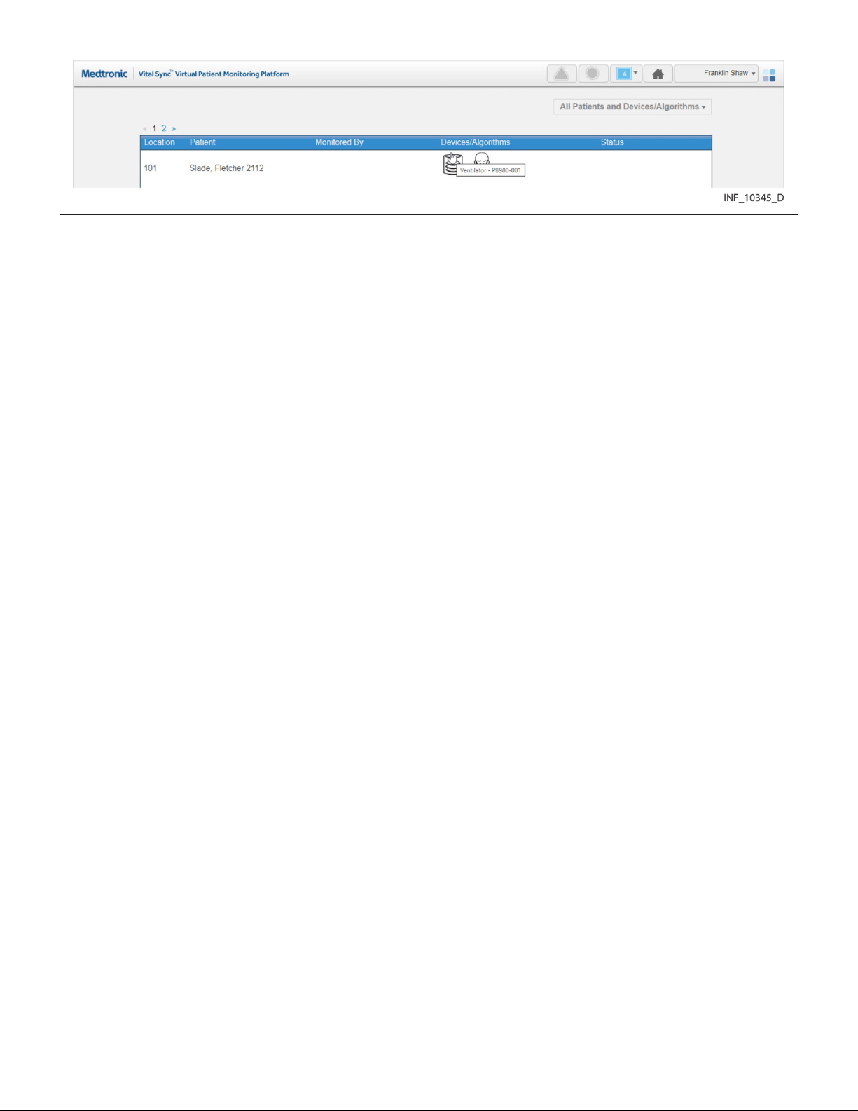
Figure 10. Tool Tip
Tool tips will appear when hovering over some controls in the Device Detail and Reports screens, and
also when hovering over device icons in the Tile View and All Patients and Devices screens.
5.4 Tile View (Patient Overview Screen)
The Patient Overview screen (generally referred to as the Tile View) is the home screen for clinicians
and supervisors; for those users, it appears automatically after login. To access the Tile View from
elsewhere in the platform at any time, click on the Home button on the navigation bar, or hover over the
navigation bar’s user function button and select Tile View from the menu.
The Tile View shows identifiers, key monitored parameters, and device messages for multiple patients
and devices or derived parameter algorithms simultaneously via bed and device tiles.
Note: Illustrations of derived parameter algorithms in this section show generic algorithm icons and
data. Each individual algorithm has its own specific parameters, and may have a specific icon (not
shown here). Basic platform behavior described here is the same for all algorithms.
48
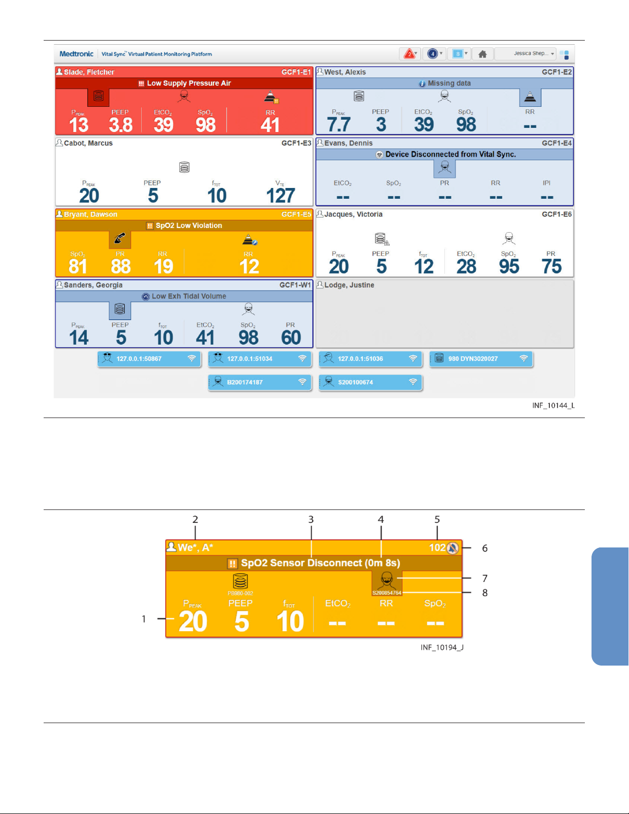
Figure 11. Patient Overview Screen (Tile View)
Each large tile on the screen represents a single bed. If a patient is present in the bed, the tile will show
the patient’s name and linked devices (if any). If no patient is present, but at least one device is
associated with the bed, icons for any devices associated with the bed will appear. See Section 6.9,
Manage Device Inventory, page 135 and Section 5.4.2, Tile Information, page 50.
Figure 12. Bed Tile Detail
1 Key monitored parameters
2 Patient name
3 Device message (highlighting indicates associated device)
4 Time elapsed for the alarm in the platform
5 Location
6 Silence icon (if an audible alert is silenced for this patient)
7 Device type icon
8 Device identifier
Each small tile on the screen represents a single device that is currently in the device inventory, but is
not currently linked to any patient or associated with any bed.
49

Figure 13. Device Tile Detail
1 Device type icon
2 Device identifier
3 Device connection icon
Note: Unless otherwise specified, the term “device” refers to patient devices (for example, pulse
oximeters, ventilators, or capnography monitors), not smartphones, tablets, or optional dedicated
bedside display units used to access and perform functions in the software.
5.4.1 Availability by User Role
Clinicians, supervisors, and central monitoring station users may use all functions in the Tile View.
Bedside unit users may view only the bed tile for the bed associated with the dedicated bedside display
unit. Link managers do not have access to the Tile View.
5.4.2 Tile Information
Bed tiles show patient information and data from linked devices. If alarms or notifications are active on
a linked device or algorithm, the bed tile will show a message and will change color to indicate the priority
of the event.
Note: Unless otherwise indicated, the term “linked device” can also be used to refer to a derived
parameter algorithm (DPA) linked to a patient in the platform.
Information shown in each bed tile includes:
• Patient Data—The patient name (if any)
• Device Message—If alarms or notifications are active on any device linked with this patient, a
message for the alarm or notification with the highest priority (the text of the alarm or notification
message is the same as that which appears on the device itself)
• Location—The bed number in the platform (see Section 6.8.2, Manage Beds, page 132 for details
on setting up beds)
• Device Type Icon—Icons showing the type of device or devices linked to this patient; if an alarm or
notification message is currently shown on the bed tile, the icon denoting the device involved will be
highlighted
• Key Monitored Parameters—Important parameters for each linked device (parameters shown
will vary by device and by the communication protocol the device uses)
Device tiles show the device type and device identifier for each device not currently linked to a patient
or associated with a bed.
Hovering the cursor over a device type icon on a bed tile will open a tool tip showing the device serial
number. Hovering the cursor over a device tile will open a tool tip showing the device model.
This release of the software allows the following standard parameters to appear on bed tiles:
• Pulse oximeters—Blood oxygen saturation (SpO2) and pulse rate (PR)
• Capnography monitors and multiparameter monitors—End tidal carbon dioxide level
(ETCO2), blood oxygen saturation (SpO2), pulse rate (PR), and respiration rate (RR)
50

• Ventilators—Peak inspiratory circuit pressure (P
total respiratory rate (f
), and exhaled tidal volume (VTE)
TOT
), positive end expiratory pressure (PEEP),
PEAK
• Regional saturation monitors—Regional saturation of oxygen (rSO2) and blood volume index
(BVI)
• Bispectral index monitors—Bilateral bispectral index (BIS) and electromyography (EMG) values
• Early warning score algorithms (if used)—The current early warning score value
• Spontaneous breathing trial algorithms (if used)—Fraction of inspired oxygen (FiO2) and
blood oxygen saturation (SpO2) when evaluating weaning readiness, or the current status or
outcome of the actual trial
Not all devices may measure all parameters listed here, and some communication protocols limit the
types of data reported to the platform. If not measured or reported, the parameter will not appear on the
tile.
• Note: Parameter unit conversion in the software may result in some loss of precision due to decimal
rounding.
• Note: Additional device parameters not shown on bed tiles in the standard configuration of the
software may be available for use with additional configuration. Consult the Medtronic Solution
Delivery Team for more information.
• Note: The platform’s data displays are informational. Except as specified for derived parameter
algorithms with adjustable alarm thresholds, the platform does not provide the ability to change
device settings or control linked devices in any way (including adjusting or silencing device alarms).
• Note: Before acting on information shown in the platform, assess the patient at the bedside.
5.4.3 Bed Tile Colors
Bed tile colors depend on whether or not a patient is present or has linked devices, and on whether any
device linked with the patient in the bed in question has active alarms or notifications.
• Grey—Indicates a patient with no linked devices, or (if no patient name is shown) an empty bed
• White—Indicates no active alarms or notifications on any of this patient’s linked devices, or
indicates a bed with no patient, but with at least one associated device
• Yellow—Indicates at least one low-priority or medium-priority alarm is active on at least one device
linked to the patient in this bed
• Red—Indicates at least one high-priority alarm is active on at least one device linked to the patient
in this bed
• Blue—Indicates at least one standard notification is active on at least one device linked to the
patient in this bed
• Light Yellow—Indicates at least one unfavorable patient event notification is active on at least one
device linked to the patient in this bed
• Green—Indicates at least one favorable patient event notification is active on at least one device
linked to the patient in this bed
If multiple alarms or notifications are active, the alarm or notification with the highest priority determines
the color of the tile. See Section 7.7, Event Priority, page 169 and Section 7.2.1, Visual Indicators,
page 159 (for alarms) or Section 8.2.1, Visual Indicators, page 171 (for notifications).
Note: The same tile color is used for medium-priority and low-priority alarms. The alarm symbol in the
message area of the tile denotes the specific alarm priority. See Section 2.5, User Interface Symbols,
page 20.
Note: The colors that appear in the bed tile are also used to indicate alarms and notifications in various
locations in the Device Detail screen. See Section 7.2.1, Visual Indicators, page 159 or Section 8.2.1.
51
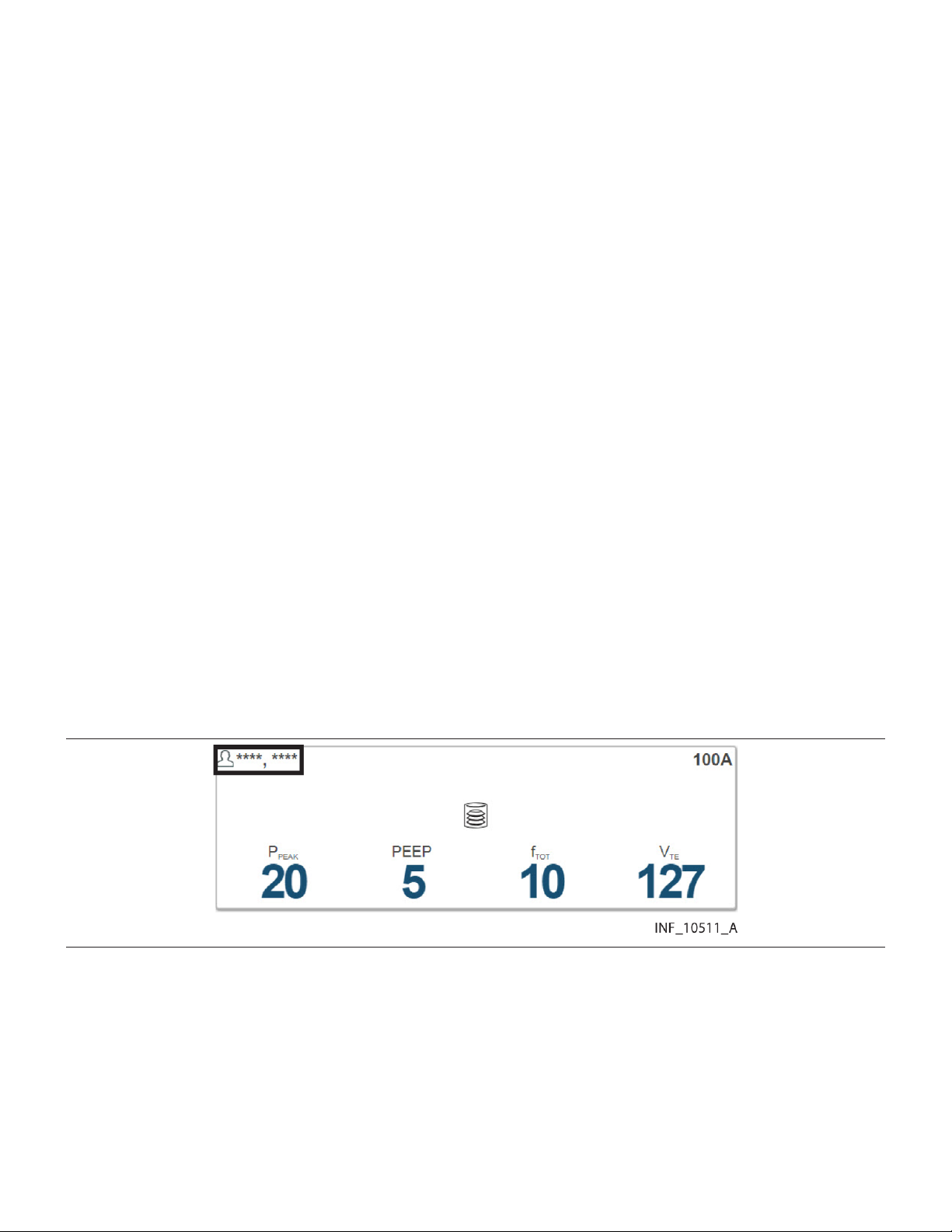
5.4.4 Additional Tile View Functions
For user convenience, additional sorting and view settings are available for the Tile View.
To access, hover over Tile View on the user function menu to open the Tile View function submenu.
Note: Selections made in the Tile View function submenu persist for the user in question or at a central
monitoring station until actively changed.
5.4.4.1 Sort Order
To sort tiles alphabetically by patient last name, select Sort by Name in the Tile View function submenu.
To sort tiles alphanumerically by patient location, select Sort by Location. The default sort order is by
location.
5.4.4.2 Device Identifiers
Device identifiers appear below device icons on bed tiles by default. To hide device identifiers on bed
tiles, select Hide Device ID in the Tile View function submenu. To once again show identifiers, select
Show Device ID.
5.4.4.3 Available Devices
Devices available to the current user (that is, assigned to one of the user’s assigned areas) appear in the
Tile View by default. To show all available devices in the Tile View, regardless of user, select Show All
Available Devices in the Tile View function submenu. To show only devices available to the current
user, select Show My Available Devices.
Note: Devices not assigned to any area will show as available regardless of the view mode selected.
See Section 5.11, Area Assignments, page 94 for information on assigning areas to users; see
Section 6.9, Manage Device Inventory, page 135 for information on assigning devices to areas.
5.4.4.4 Patient Names
Patient names are masked on bed tiles by default. Depending on the setting selected, masking replaces
some or all of patients’ first and last names with one or more asterisks. See Figure 14 for an example.
Figure 14. Bed Tile (patient name masked)
To show patient names in the Tile View, select Show Patient Name in the Tile View function submenu.
To once again mask patient names, select Mask Patient Name.
Note: To enhance patient privacy, ensure that the Tile View is set to mask patient names if the screen
on which the Tile View is visible is in an open or heavily trafficked area, such as a central monitoring
station.
Note: The Sort by Name function will still work correctly even if names are masked.
52

5.4.4.5 Empty Bed Tiles
Tiles for empty beds (that is, beds with no associated patients or devices) are hidden in the Tile View by
default. To show tiles in the Tile View for all beds assigned to the current user, including empty beds,
select Show Empty Beds in the Tile View function submenu. To once again hide tiles for empty beds,
select Hide Empty Beds.
5.5 Device Detail Screen
Users can view detailed information about device and algorithm parameters and settings and active
alarms and notifications for a patient in the Device Detail screen. From here, users can also link patients
with devices and algorithms, manage device links, and edit certain patient information.
To access the Device Detail screen, click on any Tile View bed tile, or select a patient listed in the Alarm
or Notification menus.
• Note: Before acting on information shown in the platform, assess the patient at the bedside.
• Note: The platform’s data displays are informational. Except as specified for derived parameter
algorithms with adjustable alarm thresholds, the platform does not provide the ability to change
settings or control devices in any way (including adjusting or silencing device alarms).
• Note: Illustrations of derived parameter algorithms in this section show generic algorithm icons and
data. Each individual algorithm has its own specific parameters, and may have a specific icon (not
shown here). Basic platform behavior described here is the same for all algorithms.
5.5.1 Availability by User Role
Clinicians, supervisors, central monitoring station users, and link managers may use all functions in the
Device Detail screen. Bedside unit users have view-only access to detail for devices linked to the patient
in the associated bed, and to patient detail.
5.5.2 Screen Layout
The Device Detail screen is divided into panels that show data for the patient and the selected device
or algorithm.
General screen features are shown in Figure 15, Figure 16, and Figure 17.
53

Figure 15. Device Detail Screen Layout (ventilator)
1 Patient header panel
2 Device header panel
3 Parameter panel
4 Waveform panel
5 Setting panel
6 Event panel
54
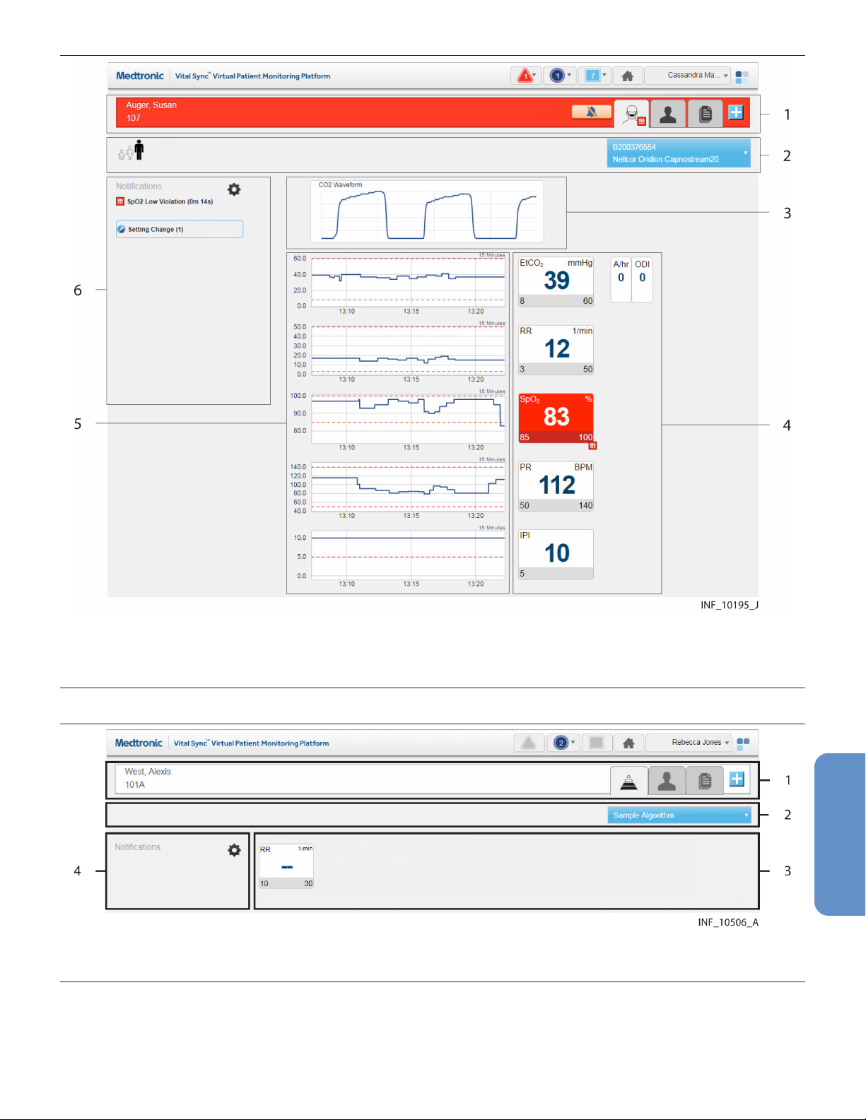
Figure 16. Device Detail Screen Layout (pulse oximeter or capnography monitor)
1 Patient header panel
2 Device header panel
3 Waveform panel
4 Parameter panel
5 Trend panel
6 Event panel
Figure 17. Device Detail Screen Layout (derived parameter algorithm)
1 Patient header panel
2 Device header panel
3 Algorithm data panel
4 Waveform panel
The Device Detail screen layout for multiparameter monitors is similar to Figure 16, but does not include
a waveform panel.
55
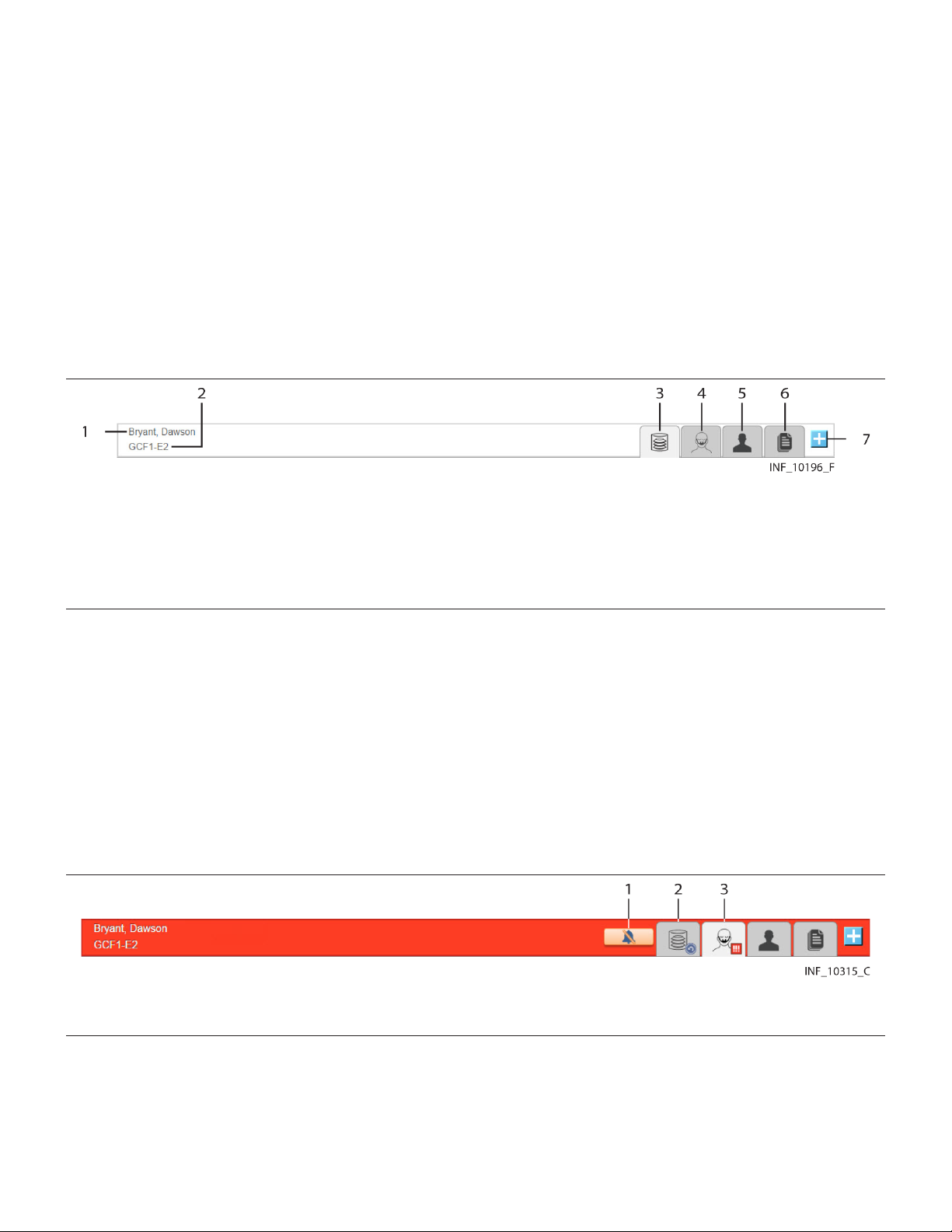
The Device Detail screen layout for regional saturation monitors and bispectral index monitors is similar
to Figure 17, and does not include a waveform or trend panel.
Derived parameter algorithms will have Device Detail screens specifically designed for the algorithm
and the parameters monitored. For more information on the Device Detail screen for any algorithm,
contact the Medtronic Solution Delivery Team.
Note: The screen captures for the Device Detail screen show examples of data for specific device types.
Data appearing on the Device Detail screen will vary by device type, and also among devices of the
same type, depending on operation mode and settings, parameters supported, and the communication
protocol used. Not all data shown in the screen captures may be shown for all devices.
5.5.2.1 Patient Header Panel
The patient header panel at the top of the screen (just below the navigation bar) shows information for
the currently selected patient.
Figure 18. Patient Header Panel
1 Patient ID information
2 Patient location
3 Device tab (device or algorithm currently selected)
4 Device tab (other device or algorithm)
5 Patient Detail tab
6 Patient Reports tab
7 Link New Device/Algorithm button
Patient data includes room number or location identifier, patient name, and patient ID number. Device
icons on tabs denote each device or algorithm currently linked to this patient. The icon for the currently
selected device or algorithm appears on a lighter-colored tab.
To select the device or algorithm for which to show detail on the Device Detail screen, click a device tab.
See Section 5.5.3, Select a Device, page 65.
The patient header shown in Figure 18 indicates no active alarms or notifications on any of the patient’s
linked devices. If any linked device or algorithm has active alarms or notifications, the patient header will
change color to indicate the event with the highest priority among all devices and algorithms linked to
this patient.
Figure 19. Patient Header Panel (alarm indicated)
1 Silence Audible Alerts button
2 Tab indicating device with other event
3 Tab indicating device with alarm
The device tab for any device or algorithm with an active alarm or notification will show a symbol for the
event with the highest priority on that device or for that algorithm. A button for silencing audible alerts (if
enabled) will also appear if an alarm is active. (See Section 7.5.6, Device Detail Screen (Event Panel),
page 166 or Section 8.3.5, Device Detail Screen (Event Panel), page 177, and Section 7.4, Audible
Alerts and Alarms, page 161.)
56

To link another device to this patient, click the Link New Device button. See Section 5.7, Admit a Patient,
page 76.
To view patient information, click on the Patient Detail tab. See Section 5.5.7, Manage Patient Detail,
page 70.
To access reports for this patient without leaving the Device Detail screen, click the Patient Reports tab.
See Figure 164, page 193.
5.5.2.2 Device Header Panel
Basic mode and identifier information for the device appears in the device header, just below the patient
header.
Figure 20. Device Header Panel (ventilator)
Information shown in the device header for a ventilator includes some or all of the following items, if
supported on the device or by the device’s communication protocol:
• Circuit type (adult, pediatric, or neonatal)
• Ventilation mode
• Mandatory breath type
• Trigger type
• Ventilation type
• Spontaneous breath type
• Device model and identifier (shown on the blue function button)
Figure 21. Device Header Panel (pulse oximeter or capnography monitor)
Figure 22. Device Header Panel (regional saturation monitor)
Information shown in the device header for a pulse oximeter, capnography monitor, or regional
saturation monitor includes some or all of the following, if supported on the device or by the device’s
communication protocol:
• Patient type
• Signal strength from sensor
• Sensor type
• Battery charge remaining
• Sensor identifier (serial and lot number)
• Device model and identifier (shown on the blue function button)
To disconnect or reconnect devices in the platform, use the drop-down function menu on this panel. See
Section 5.5.4, Manage Device Connections, page 65.
57
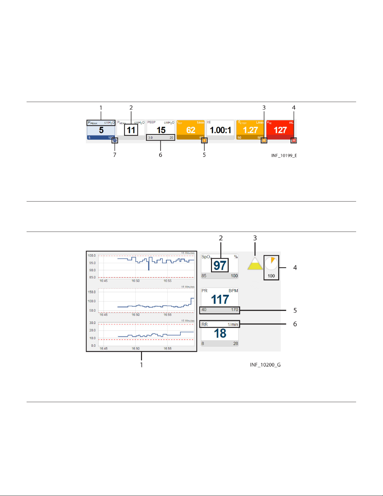
Note: Information appearing in the device header depends on device type and mode of operation and
the communication protocol used. Not all devices support display of all possible information, and some
information is not applicable in certain modes of operation. See the operator’s manual for the device for
more information on specific data shown.
5.5.2.3 Parameter Panel
The most recent parameter data reported for the device (unless data is not available for that parameter)
appears on tiles in the parameter panel.
Figure 23. Parameter Panel (ventilator data)
1 Parameter name and unit of measure
2 Parameter value
3 Medium-priority alarm icon
4 High-priority alarm icon
5 Low-priority alarm icon
6 Parameter upper and lower alarm limits (if set or applicable)
7 Reset alarm icon
Note: The alarm priority icons shown in Figure 23 are used in parameter panels for all device types.
Figure 24. Parameter Panel (pulse oximeter data)
1 Trend panel with trend tiles
2 Parameter value
3 Saturation pattern detection (SPD) indicator (if supported)
4 SatSeconds indicator and value (if supported)
5 Parameter upper and lower alarm limits (if set or applicable)
6 Parameter name and unit of measure
58
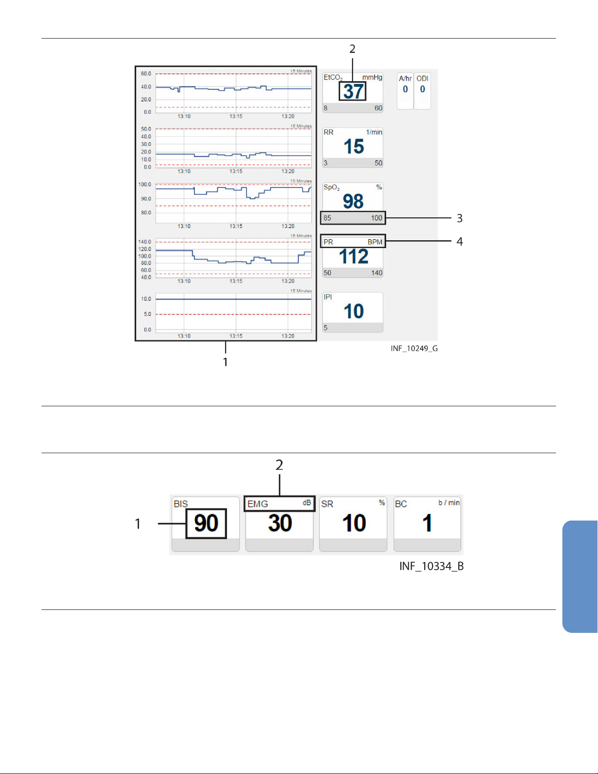
Figure 25. Parameter Panel (capnography monitor data)
1 Trend panel with trend tiles
2 Parameter value
3 Parameter upper and lower alarm limits (if set or applicable)
4 Parameter name and unit of measure
Note: For more information on trend tiles, see Section 5.5.2.6, Trend Panel, page 64.
Figure 26. Parameter Panel (bispectral index monitor data)
1 Parameter value
2 Parameter name and unit of measure
59

Figure 27. Parameter Panel (multiparameter monitor data)
1 Trend panel with trend tiles (continuous data)
2 Parameter value
3 Parameter name and unit of measure
4 Timestamp for episodic parameter
5 Trend panel with trend tiles (episodic data)
• Note: The parameter panel layout shown is for the Welch Allyn™* Connex™* 6700 and Welch
Allyn™* Connex™* 6800 vital signs monitors. Other multiparameter monitors that report different
parameters will have a different panel layout.
• Note: An episodic timestamp indicates the collection time for the parameter in question, using a
24-hour clock.
60

• Note: Episodic parameter tiles will show a missing data indicator (“- -”) and no associated
timestamp if the platform has not received data for the parameter for 24 hours.
• Note: For more information on trend tiles, see Section 5.5.2.6, Trend Panel, page 64.
Figure 28. Parameter Panel (four-channel regional saturation monitor data)
1 Sensor channel
2 Parameter value
3 Parameter name and unit of measure
4 Parameter upper and lower alarm limits (if set)
Figure 29. Parameter Panel (two-channel regional saturation monitor data)
61
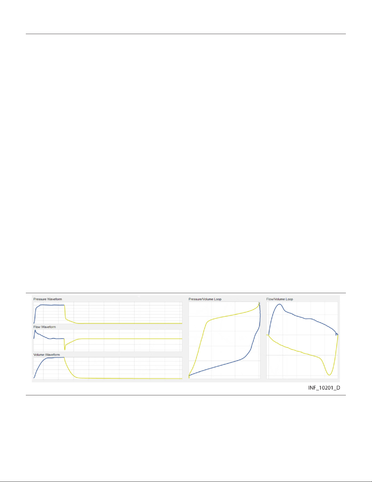
1 Parameter value
2 Sensor channel
3 Parameter upper and lower alarm limits (if set)
4 Parameter name and unit of measure
• Note: Not all devices monitor all parameters the platform can show for that device type. If the device
does not monitor a particular parameter, the tile for that parameter will not appear in the parameter
panel.
• Note: The screen captures for the Device Detail screen show examples of data for specific device
types. Data appearing on the Device Detail screen will vary by device type, and also among devices
of the same type, depending on operation mode and settings, parameters supported, and the
communication protocol used. Not all data shown in the screen captures may be shown for all
devices.
• Note: If an audible alert sounds, the alert will be related to the alarm message with the highest
priority on the linked device with the highest priority. This device may not be the device that is
currently selected.
Parameters shown are specific to the device and ventilation mode or sensor type selected. Reference
the operator’s manual for the device for more information.
If data is unavailable for a parameter the device normally monitors, two dashes (- -) will appear in the tile.
Regardless of device type, if any parameters are outside alarm limits set on the device, an alarm icon
will appear below the lower right corner of the tile, and the tile will change color to red (indicating a
high-priority alarm) or yellow (indicating a low-priority or medium-priority alarm). If audible alerts are
enabled, an alert tone will also sound. See Section 7.2.2, Audible Indicators, page 160.
If a reset alarm occurs for a parameter, the reset alarm icon will appear below the lower right corner of
the tile, and the tile will change color to blue. See Section 8.2.1, Visual Indicators, page 171.
To access detailed trend data for individual parameters, click on any tile. See Section 5.5.5, View
Parameter Trend Data, page 65.
5.5.2.4 Waveform Panel
The waveform panel shows real-time waveform data for the selected device.
Figure 30. Waveform Panel (ventilator data)
For ventilators, loop waveforms (showing the most recent monitored breath) and scalar waveforms
(showing a collection of breaths over time) appear here.
62
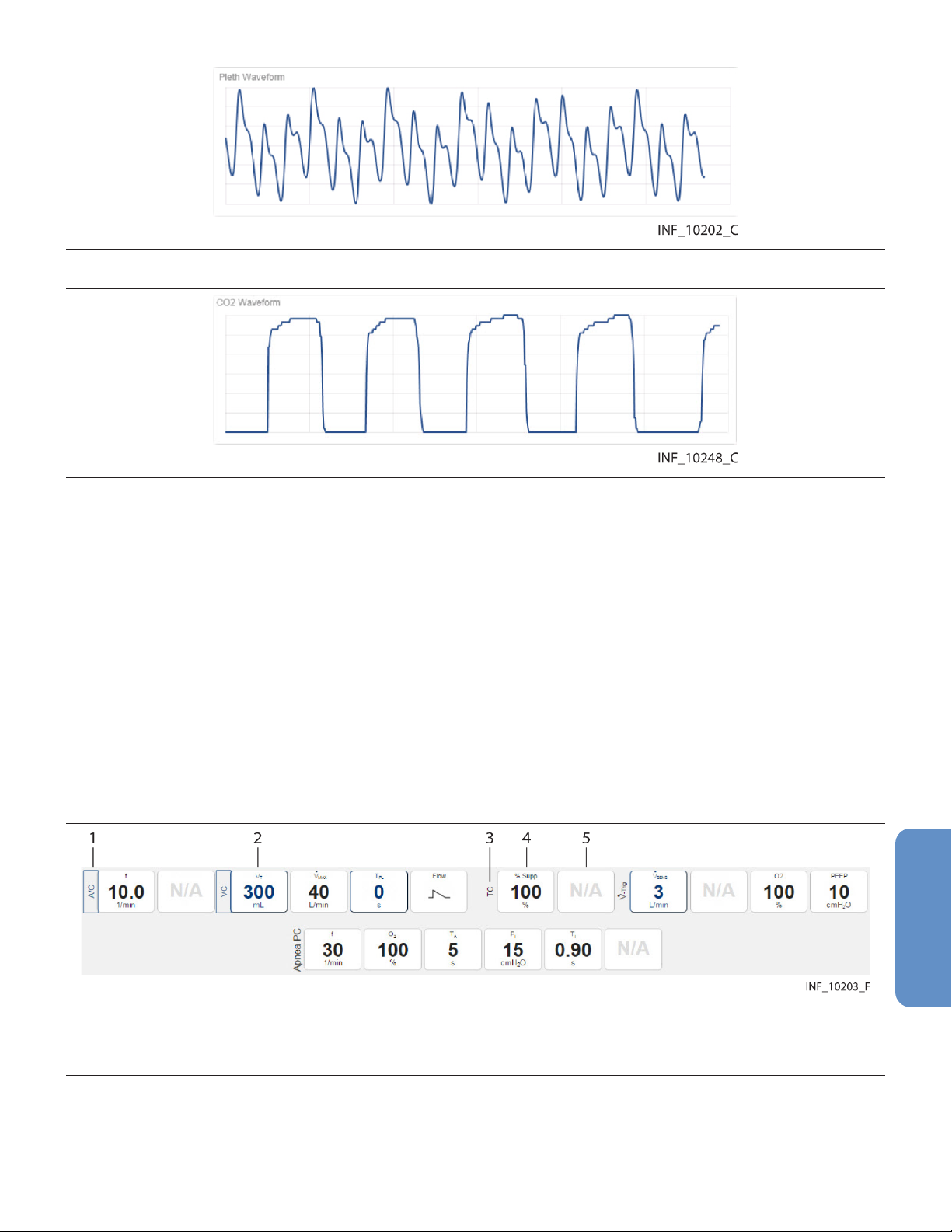
Figure 31. Waveform Panel (pulse oximeter data)
Figure 32. Waveform Panel (capnography monitor data)
For pulse oximeters and capnography monitors, waveform data for the most recent ten seconds
monitored appears here.
Waveforms shown vary by device and configuration; reference the operator’s manual for the specific
device for more information.
If a particular waveform is not supported, or data is unavailable for a supported waveform, the message
“No Data Available” will appear in the panel for that waveform.
To access more detailed information for a specific waveform, click on the waveform. See Section 5.5.6,
View Waveform Detail, page 68.
5.5.2.5 Settings Panel
The settings panel shows the settings for the currently selected device, with indicators for unused and
changed settings.
Figure 33. Settings Panel (ventilator settings)
1 Device mode label (mode changed)
2 Settings tile (setting changed)
3 Device mode label (mode unchanged)
4 Settings tile (setting unchanged)
5 Settings tile (setting not used or not supported)
The tile layout in the settings panel is the same regardless of the device linked; active tile content and
unused tiles are specific to the device and device mode. For details on settings, reference the operator’s
manual for the specific device.
63
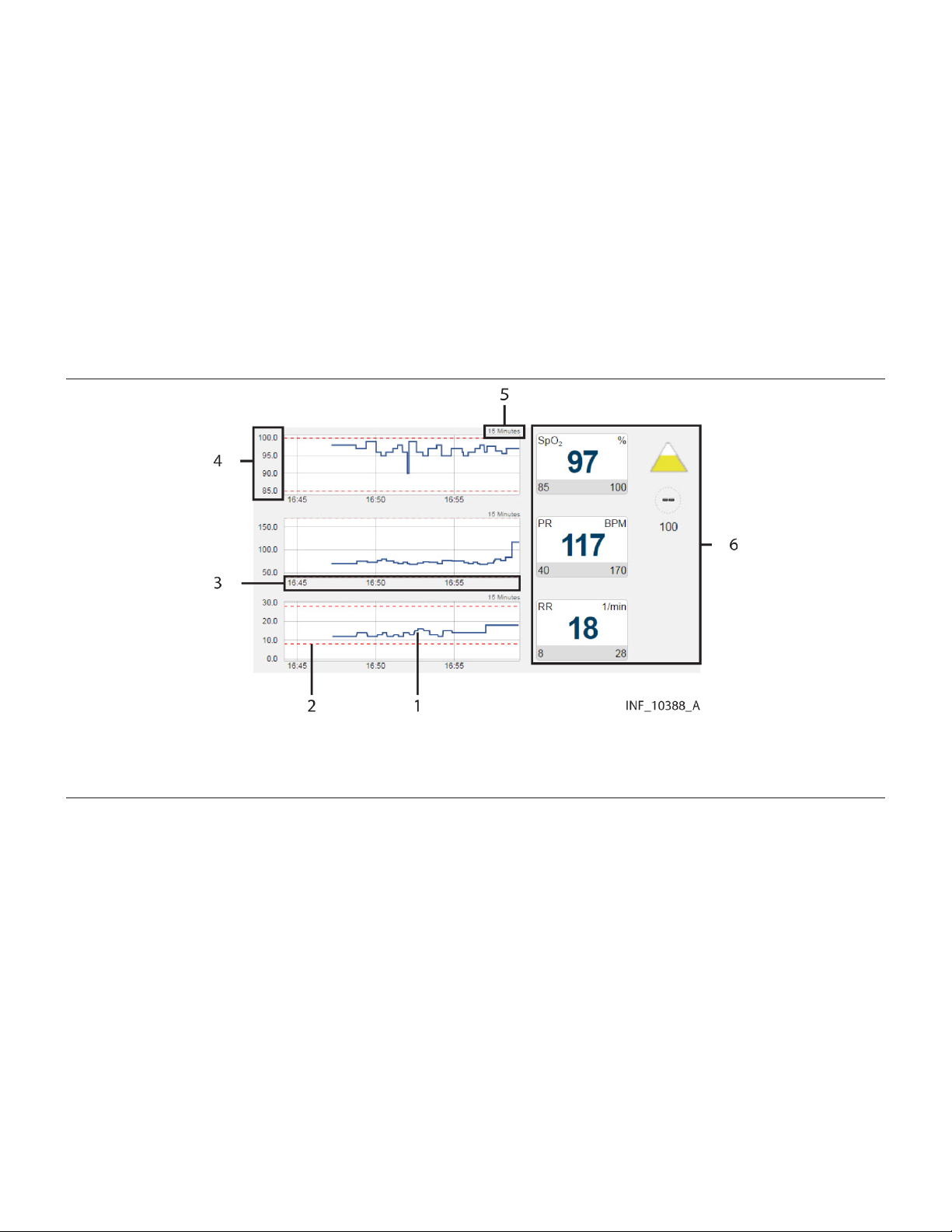
If a setting shown in the settings panel is changed on the device, the tile showing that setting will change
color to show a blue outline, or the label indicating a device mode will be outlined in blue. Click on the
tile to view details of, and acknowledge, changes to settings. See Section 8.3.6, Device Detail Screen
(Settings Panel), page 177.
Note: The Device Detail screen settings panel only shows settings data for ventilators.
Note: Changes made on the device to any setting shown in the settings panel will trigger a setting
change notification in the event panel. Changes to any alarm limit setting will also trigger a setting
change notification in the event panel, but are not denoted on the corresponding tile in the parameter
panel.
5.5.2.6 Trend Panel
The trend panel shows trend data for the previous 15 minutes for parameters measured by the currently
selected device.
Figure 34. Trend Panel
1 Parameter trend line
2 Parameter alarm limit indicator line
3 Parameter trend time axis
4 Parameter trend value axis
5 Parameter trend time interval indicator
6 Parameter panel with parameter tiles
In addition to the trend line, each trend tile has dotted indicator lines for upper and lower alarm limits for
the associated parameter, as set on the device (and if the device reports them to the platform). For
details on settings, reference the operator’s manual for the specific device.
Note: The Device Detail screen trend panel only shows trend data for pulse oximeters, capnography
devices, and certain multiparameter monitors.
Note: Clicking on a parameter trend tile will open the Parameter Trend window for that parameter.
5.5.2.7 Event Panel
The event panel shows recent device alarms and notifications that require the user to acknowledge
them.
64

Figure 35. Event Panel
1 Alarm/notification icon
2 Alarm/notification message
3 Settings icon
4 Time elapsed since alarm or notification onset
5 Setting change indicator
To view details of alarms, or to view details of and acknowledge notifications, click on an alarm or a
notification message. See Section 7.5.6, Device Detail Screen (Event Panel), page 166 or
Section 8.3.5, Device Detail Screen (Event Panel), page 177.
5.5.3 Select a Device
When initially accessed, the Device Detail screen shows details for the device with the highest priority,
based on device type, whether the device is the primary device, and on priority of active alarms if any
are present.
To select a different device:
1. Find the tab showing the icon for the desired device in the patient header panel.
2. Click on the tab for the desired device. Data for the device will appear in the other panels on the
screen.
See Section 7.7, Event Priority, page 169 for device priority details.
5.5.4 Manage Device Connections
Users can access device connection controls from the device header panel to attempt to reconnect or
replace devices that have lost communication with the platform, or to unlink devices from patients in the
platform.
See Section 5.7.6, Device Connection Functions, page 81 for details.
5.5.5 View Parameter Trend Data
To view recent trend data (including alarm conditions and setting changes) for a parameter, click on the
desired parameter tile to open the Parameter Trend window.
65
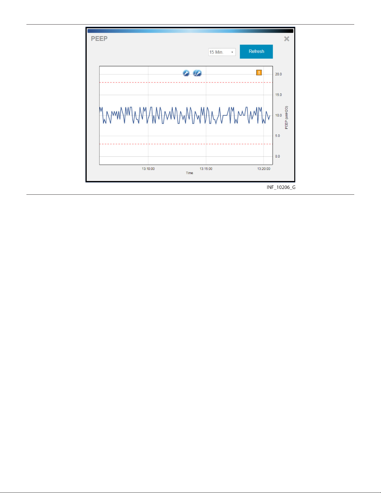
Figure 36. Parameter Trend Window
5.5.5.1 Default Data
The default data shown is for the previous 15 minutes. Click on the drop-down box at lower left for other
options (30 minutes, or 1, 2, or 4 hours).
Upper and lower alarm limits set on the device for this parameter are indicated by red dotted lines. (The
vertical axis is scaled automatically according to the limits set for the parameter.)
5.5.5.2 Additional View Options
Alarms and setting changes occurring during the timeframe shown are indicated on the trend graph with
appropriate icons. To view the alarm message associated with an alarm, click the desired alarm icon.
66
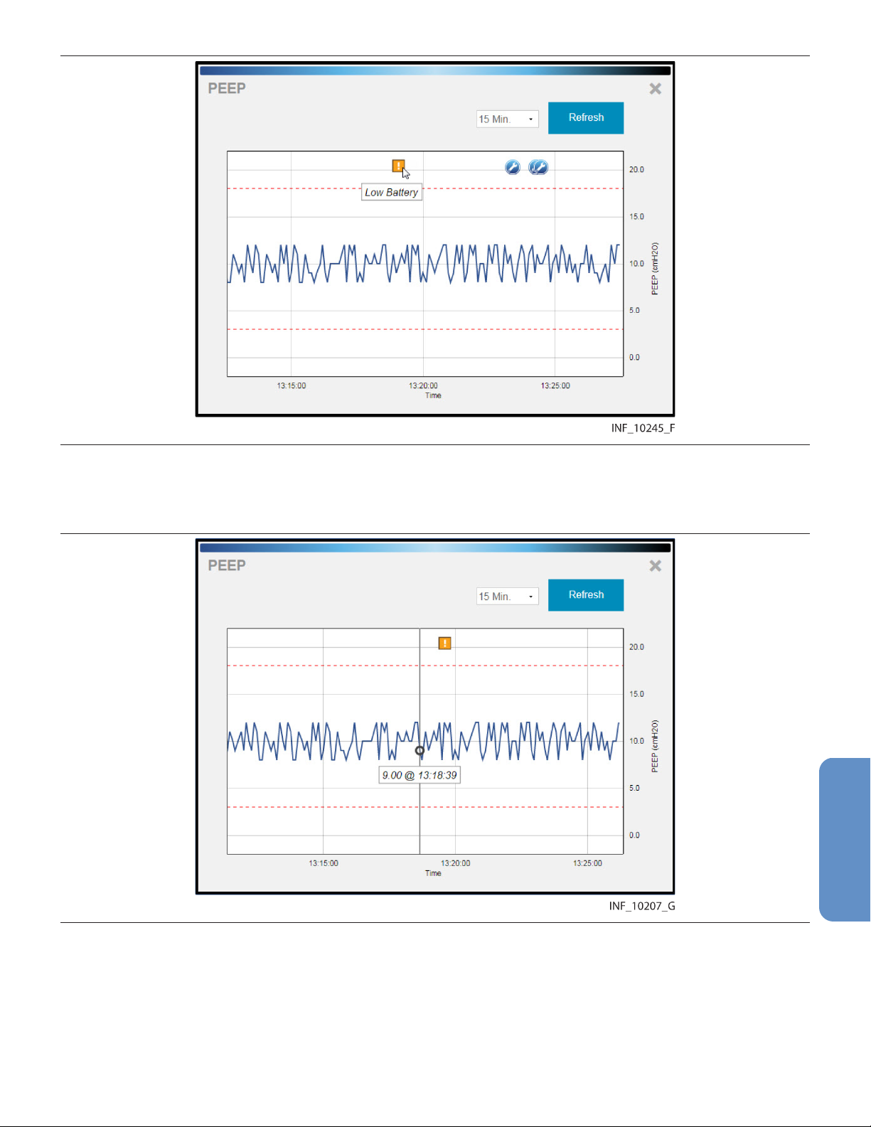
Figure 37. Parameter Trend Window (alarm and setting change icons and alarm message shown)
To get the exact value for the parameter at any point on the trend data graph, simply click on the line at
the desired time point.
Figure 38. Parameter Trend Window (specific data point shown)
To view a different part of the trend graph not currently shown (if any), click and drag the graph to either
the left or the right.
To refresh the trend graph to show the most recent data, click Refresh.
To close the Parameter Trend window, click the X at upper right in the window.
67
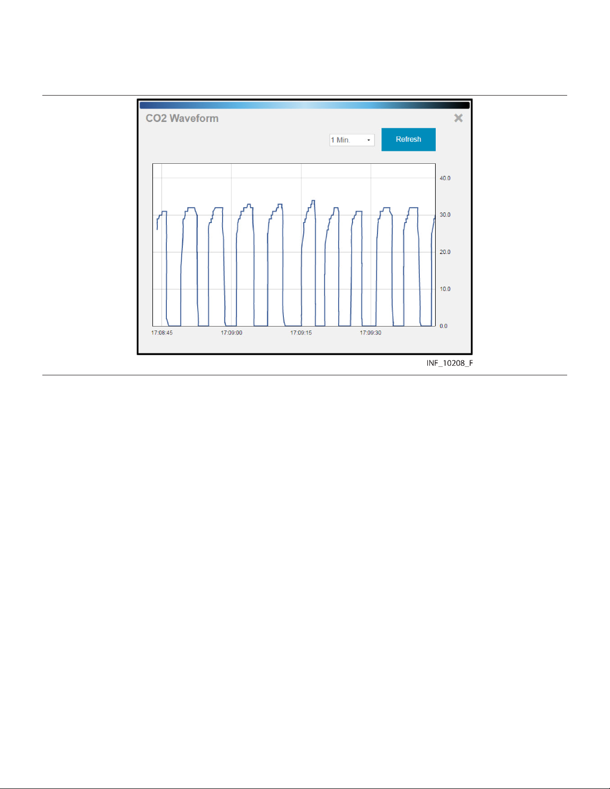
5.5.6 View Waveform Detail
To view a more detailed view of any waveform shown in the waveform panel, click on the desired
waveform to open the Waveform Detail window.
Figure 39. Waveform Detail Window
5.5.6.1 Default Data
The default data shown is for the previous breath for a ventilator waveform, or for the previous minute for
waveforms from other device types. Click on the drop-down box at lower left for other options (2, 4, or
8 breaths for a ventilator waveform, or 2, 4, or 8 minutes for other waveforms).
5.5.6.2 Additional View Options
To get the exact value at any point on the waveform, simply click on the line at the desired time point.
68
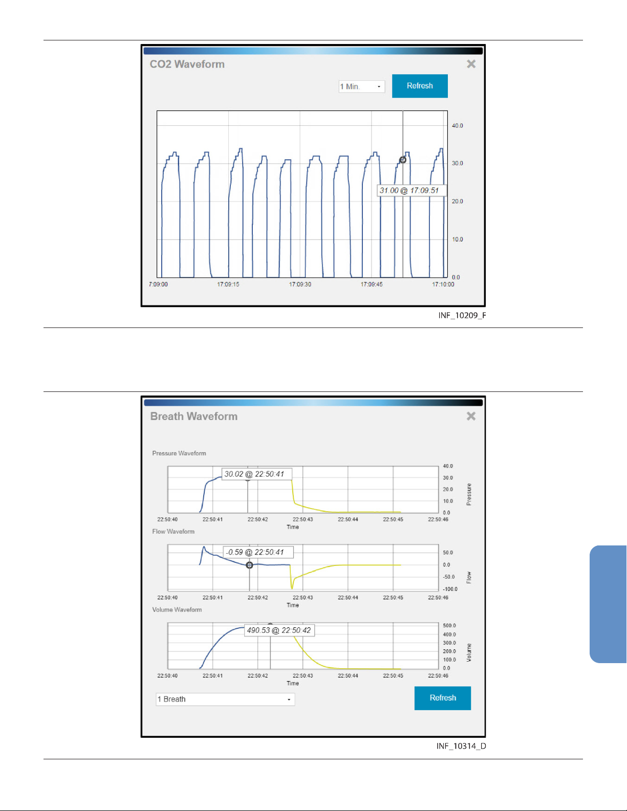
Figure 40. Waveform Detail Window (specific data shown)
If viewing waveform detail for multiple waveforms at once, specific data will be shown on all waveforms
for the time point selected. Users can select different time points for each waveform shown.
Figure 41. Waveform Detail Window (specific data shown for multiple ventilator waveforms)
69
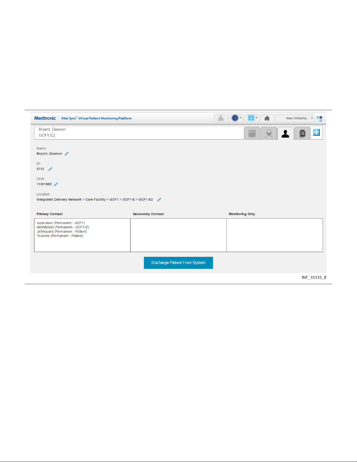
To refresh the waveform view to show the most recent data, click Refresh.
To close the Waveform Detail window, click the X at upper right in the window.
5.5.7 Manage Patient Detail
Users can view patient information, including the bed location and platform users assigned to any
patient, directly from the patient header in the Device Detail screen. Users (except for those using the
platform on optional dedicated bedside display units) can also edit identifying information and locations
for patients.
To access patient information, click the Patient Detail tab in the patient header.
Figure 42. Device Detail Screen (patient information fields)
The following information appears here:
• Name—The patient’s name (last name, middle name, first name)
• ID—The patient’s identification number
• DOB—The patient’s date of birth (if entered)
• Location—The patient’s location, including all associated areas starting with the highest-level area
and ending with the patient’s bed (for details on locations in the platform, see Section 9.3, Locations,
page 181)
• Primary Contact—The usernames and assignment types (permanent or shift-based) of all users
who have primary responsibility in the platform for this patient
• Secondary Contact—The usernames and assignment types (permanent or shift-based) of all
users who have secondary responsibility in the platform for this patient
• Monitoring Only—The usernames and assignment types (permanent or shift-based) of all users
who are only monitoring this patient in the platform
The Discharge Patient from System button allows the user to discharge this patient in the platform.
See Section 5.9, Discharge (Remove) a Patient, page 85 for details.
70
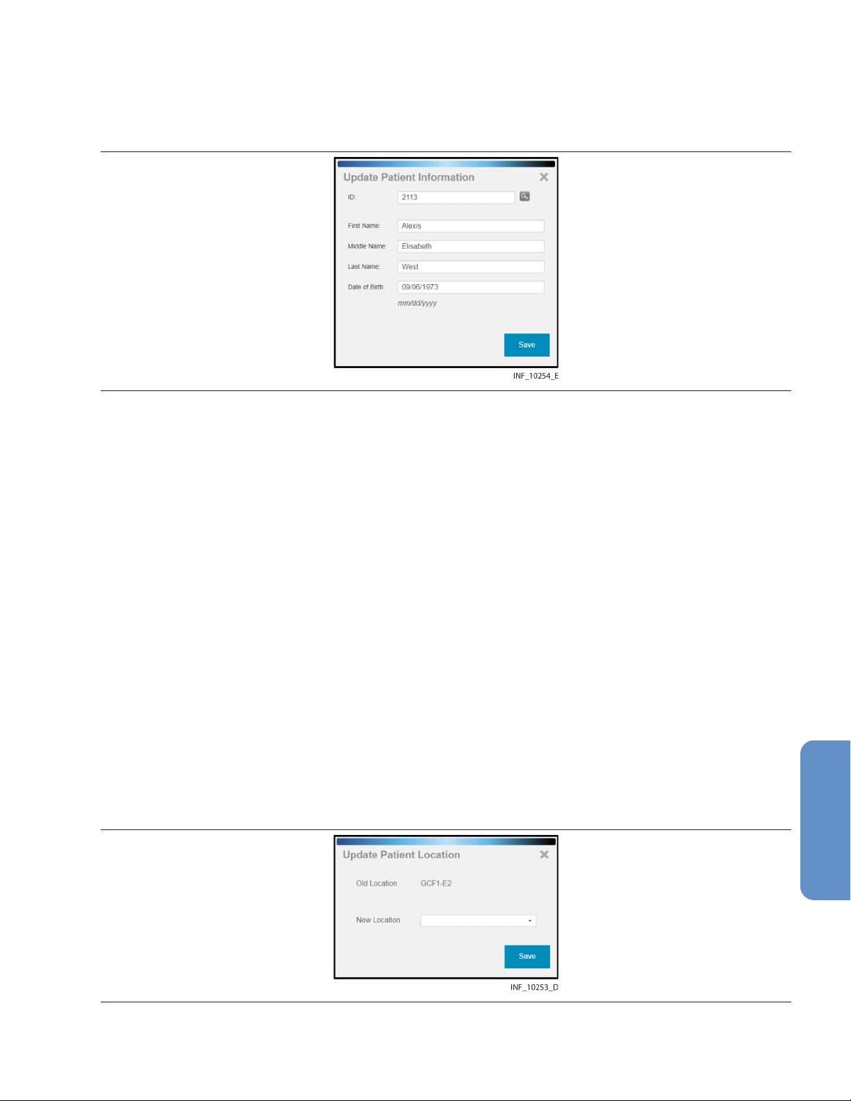
5.5.7.1 Edit Information for a Patient
To update patient information:
1. With the patient information fields shown, click on the edit button next to the Name, ID, or DOB
field to open the Update Patient Information window.
Figure 43. Update Patient Information Window
2. ID—The ID number currently used for the patient appears here. If desired, edit this number, then
click the magnifying glass icon to make sure the new number is not in use. (If changing the ID
number for the patient, all patient information will need to be reentered in this window.)
3. First Name—The first name currently used for the patient appears here. If desired, edit this name.
(This field is optional.)
4. Middle Name—The middle name currently used for the patient appears here. If desired, edit this
name. (This field is optional.)
5. Last Name—The last name currently used for the patient appears here. If desired, edit this name.
(This field is optional.)
6. Date of Birth—The date of birth currently indicated for the patient appears here. If desired, edit
this date. (This field is optional.)
7. Click Save to update the information in the platform.
5.5.7.2 Change a Patient Location
To change a patient’s location:
1. Click on the tile for the desired patient to access the Device Detail screen.
2. Click on the Patient Detail tab to access patient information.
3. Click on the edit button next to the patient’s bed number in the Location field to open the Update
Patient Location window. Figure 44. Update Patient Location Window
4. Old Location—The patient’s current bed in the platform appears here.
71
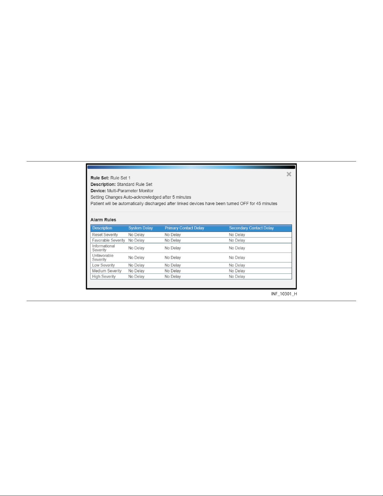
5. New Location—Click on the drop-down box to view available beds, then click on a bed in the list
to select it.
Note: Users at a central monitoring station will only be able to select beds assigned to the
designated home area (and its child areas, if any) for that station.
6. Click Save to update the location in the platform. The patient’s information will appear in the bed
tile for the new location in the Tile View.
Note: When updating a patient’s location, if any device not currently associated with the new location
is currently linked to the patient, a message will appear indicating that the patient’s new location does
not match the location associated with the device. See Section 6.9, Manage Device Inventory,
page 135 for details on updating location assignments for devices.
5.5.8 View Event Rules
To access a dialog showing current delay rules in use for alarms and notifications, click on the settings
icon in the upper right corner of the Device Detail screen event panel.
Figure 45. Rules and Settings Dialog (example delay rules shown)
The name and description of the current rule set in effect for the selected device appears at upper left.
Time periods for automatic setting change acknowledgment and automatic patient discharge, if set,
also appear.
The following information appears in the Alarm Rules panel for each event (an alarm of a particular
priority level, or a specific device alarm) defined in the rule set:
• Description—The device alarm priority level or the specific device alarm
• System Delay—The delay (if any) before the indicated event will annunciate in the platform
• Primary Contact Delay—The delay (if any) before the indicated event will trigger an email or SMS
message to users assigned to the affected patient as primary contacts
• Secondary Contact Delay—The delay (if any) before the indicated event will trigger an email or
SMS message to users assigned to the affected patient as secondary contacts
This dialog allows users to view the rule set in effect for the currently selected device, but does not allow
changes. Administrative users set up and maintain rule sets and determine where they are applied. For
more information on setting up delay rules, see Section 6.11.4, Add or Edit a Rule Set, page 141, and
Section 6.11.5, Define Alarm and Notification Rules, page 145.
72

5.5.9 Manage Settings
Users can change alert threshold settings for derived parameter algorithms and supported devices from
the Device Detail screen, using rules defined in the informatics manager.
To access a dialog showing current settings and setting rules, click on the settings icon in the upper right
corner of the Device Detail screen event panel.
Figure 46. Rules and Settings Dialog (example alert thresholds shown)
Note:
own specific settings. Basic functionality described here is the same for all algorithms.
The following information appears in the Alert Thresholds panel of the dialog for each alert supported:
To change setting rules:
For details on thresholds used with a specific algorithm, consult with the Medtronic Solution Delivery
Team.
Administrative users set the minimum, maximum, and default thresholds (that is, the Min, Max, and
Default values appearing in the Rules and Settings dialog) in the Vital Sync informatics manager. These
The alert thresholds shown in Figure 46 are purely illustrative. Individual algorithms have their
• Name—The name of the alert threshold
• Value—The value to which the alert threshold is currently set
• Min—The lowest value to which the threshold can be set
• Max—The highest value to which the threshold can be set
• Default—The default value for the alert threshold
1. Click in the Value field for the desired threshold and enter a new value. The value entered must be
no lower than the value shown in the Min field, and must be no higher than the value in the Max
field.
2. When finished, click Save to exit the dialog.
73
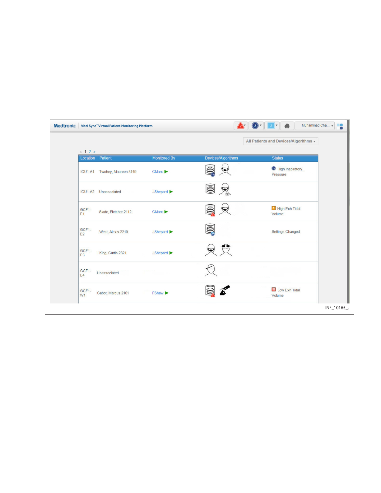
thresholds apply to all devices of a specific type that use specific setting rules in the platform. For more
information, see Section 6.11.5.3, Define a Setting Rule, page 148.
5.6 All Patients and Devices Screen
The All Patients and Devices screen provides users with a summary of all patients and linked devices,
assigned personnel, and current status. This screen is the home screen for link managers.
To access the All Patients and Devices screen:
1. Hover over the navigation bar’s user function button to access the function menu.
2. Select All Patients and Devices.
Figure 47. All Patients and Devices Screen
5.6.1 Availability by User Role
Supervisors and link managers may use all functions in the All Patients and Devices screen. Clinicians
do not have access to this screen, nor is it accessible from a central monitoring station or optional
dedicated bedside display unit.
5.6.2 Patient and Device Information
Information shown for each patient includes:
• Location—The room number or location identifier
• Patient—The patient’s name
• Monitored By—The first user to whom the patient is assigned
• Devices—The device or devices linked to the patient
• Status—The currently active alarm or notification (if any) with the highest priority
The All Patients and Devices screen shows all patients currently monitored in the platform, not just those
patients who are assigned to the supervisor currently logged in. There may be multiple pages of patients
74

and devices; if the desired patient or device is not immediately visible, navigate through additional
pages to find the patient or device.
Note: Before acting on information shown in the platform, assess the patient at the bedside.
Note: The platform’s data displays are informational. Except as specified for derived parameter
algorithms with adjustable alarm thresholds, the platform does not provide the ability to change settings
or control linked devices in any way (including adjusting or silencing device alarms).
5.6.3 Additional View Options
The default view for the All Patients and Devices screen is of all patients currently monitored in the
platform, along with all devices currently linked to patients. Users can also view currently unassigned
patients and devices.
To change the patient and device view:
1. Hover over the drop-down menu near the upper right corner of the screen.
2. To show only devices communicating with the platform but not currently linked to any patients,
select Unassigned Devices. To show only patients not currently assigned to any users, select
Unassigned Patients. To select all patients regardless of status, select All Patients. A check
mark will appear next to the currently selected view option.
If there are no unassigned patients or devices, a message indicating as such will appear after selecting
the view option.
5.6.4 View Patient and Device Detail
Users can access the Device Detail screen from the All Patients and Devices screen.
To access patient and device detail:
1. Navigate the All Patients and Devices screen until the row for the desired patient is visible.
2. Click anywhere in the row showing the desired patient. The Device Detail screen will appear.
See Section 5.5, Device Detail Screen, page 53 for more information.
5.6.5 View Patient Assignments
The first user to whom a patient is assigned appears in the Monitored By field.
To view all users to whom a patient is assigned:
1. Navigate the All Patients and Devices screen until the row for the desired patient is visible.
2. Hover over the green triangle in the Monitored By field. The names of all users to whom the
patient is assigned will appear in a tool tip next to the mouse cursor.
75

Figure 48. All Patients and Devices Screen (assignments shown for a patient)
5.7 Admit a Patient
For users to be able to view device data for a patient, the patient must be admitted in the platform, with
one or more devices linked.
Users can manually admit patients in the platform at any time. If the facility has an admission, discharge,
and transfer (ADT) system, automatic admission of patients is also available with proper configuration.
Note: The terms “device category” (as used in the software user interface and in this section) and
“device type” (as used elsewhere in this manual) are interchangeable.
5.7.1 Availability by User Role
Clinicians, supervisors, link managers, and central monitoring station users may use all functions in the
Admit Patient screen. Bedside unit users do not have access to the Admit Patient screen.
Clinicians, supervisors, link managers, and central monitoring station users may use all other device
linking and device connection functions. Bedside unit users cannot use these functions, since their
access to device detail is view-only.
Note: If a monitoring station has a home area designated for it in the platform, user function at that
station is limited to patients and devices accessible from that area or its child areas.
Automatic admission does not require user action. Once a patient is automatically admitted, the same
functions usable for manually admitted patients are available.
5.7.2 Manual Admission
Users admit patients in the platform and link devices and derived parameter algorithms to those patients
via the Admit Patient screen.
Once a patient is admitted in the platform and a patient record is created, the Device Detail screen offers
the ability to link additional devices, choose primary devices, manage connections, and manage certain
patient data.
5.7.2.1 Access
To access the Admit Patient screen from any screen:
1. Hover over the navigation bar’s user function button to access the function menu.
2. Select Admit Patient.
76

To access the Admit Patient screen from the Tile View, do any of the following:
• Drag and drop a tile for the desired unassociated device (if it is visible in the Tile View) onto the
desired bed tile. A dotted line will appear around the edge of the bed tile.
Figure 49. Tile View (device tile dragged onto bed tile at lower left)
• Click on a tile for an unassociated device not currently linked to any patient.
• Click on an empty bed tile.
Figure 50. Admit Patient Screen
Information appearing in the Admit Patient screen varies depending on how the user accesses it.
• If accessed from the user function menu, all fields will be empty.
• If accessed by dragging and dropping a device tile onto a bed tile in the Tile View, location and
device information will appear. If a patient is already assigned to the bed, that patient’s information
will also appear.
77

• If accessed by clicking a bed tile in the Tile View, location information will appear; other fields will be
empty.
• If accessed by clicking a device tile in the Tile View, device information will appear; other fields will
be empty.
Note: If the facility’s ADT system has sent a message to the platform indicating a patient admission or
transfer to the bed viewed, patient information for that patient will appear regardless of the user’s means
of accessing the screen.
5.7.2.2 Field Entry
Note: Instructions for all field entries in this screen are presented in this section. However, not all fields
may require entries or be immediately editable, depending on how the user accesses the screen and
whether patient information is already shown because of automatic admission.
To enter location and patient information when admitting a patient in the platform:
1. Location—Select the desired bed from the drop-down list. (If the desired bed is already selected,
skip this step.)
Note: If viewing this screen from a monitoring station that has a designated home area, the only
available beds in this list will be those assigned to the home area or any of its child areas.
2. ID—Enter the desired patient ID, then click the search button to the right of this field. (If the patient
ID for the desired patient is already selected, skip this step.)
If a record for a patient with this ID number is already present, current information for that patient
will appear, including linked devices.
If this is a new patient, a message will appear indicating the ID number was not found. Completing
admission in the platform will create a record in the software for the new patient.
3. First Name—Enter the patient’s first name. This field is optional.
4. Middle Name—Enter the patient’s middle name. This field is optional.
5. Last Name—Enter the patient’s last name. This field is optional.
6. Date of Birth—Enter the patient’s date of birth, following the date format shown in the lower left
corner of the screen. This field is optional.
After entering or confirming location and patient information, link any available device or algorithm.
Note: A device is considered available if it is currently in the device inventory, connected to and
communicating with the platform, and not associated with another patient or another bed. For a
monitoring station with a designated home area, available devices are also limited to those accessible
in the platform within the home area or one of its child areas.
To link a device or algorithm when admitting a patient in the platform:
1. Category—Select the category for the device or algorithm to be linked from the list of available
categories. (If a device or algorithm is already selected, the category will automatically appear
here; if the category is correct, skip this step.)
2. ID—Select the desired device or algorithm from the drop-down list. Devices are listed by serial
number or network address, while algorithms are listed by name. (If a device or algorithm is
already selected, its information will automatically appear here; if the information matches the
desired device or algorithm, skip this step.)
78

Figure 51. Admit Patient Screen (available device list)
Note: Users at a monitoring station with a designated home area will only see available devices
accessible in the platform from within that area or its child areas.
Note: Algorithms must be activated in the software to be available for selection. See
Section 6.14.4, Activate or Deactivate an Algorithm, page 155.
3. Once all fields in the screen have entries, the Link button will be available. Confirm the information
on the screen is correct, including all automatically populated information.
After confirming that the information is correct, click Link to complete the admission in the
platform, linking the device or algorithm just selected to the patient. The Device Detail screen will
appear, showing data for the device or algorithm, as well as a system message describing the
operations just completed.
• Note: After linking a device to the patient in the platform, visually check the device itself to confirm
that the data it is showing also appears on the Device Detail screen for that patient.
• Note: If, after linking a device to a patient, both the patient and the linked device are moved to a
different bed, make sure the device inventory is updated to indicate the new bed association. (Refer
to Section 6.9, Manage Device Inventory, page 135.) Otherwise, an error message will appear in
the Device Detail screen indicating that the device is not in its associated location.
• Note: Linking a patient and a device adds the new patient record (if new patient data is entered), and
automatically assigns the patient to the current user. If needed, use the Patient Assignment screen
to remove the assignment. See Section 5.10, Patient Assignments, page 88.
• Note: If automatically populated patient information is incorrect, remove the number in the ID field
for the patient. The subsequent patient information fields will then be editable.
5.7.3 Automatic Admission
If the facility ADT system is integrated with the Vital Sync software, admission of a patient in the ADT
system will result in creation of a patient record and automatic admission of that patient in the platform.
The patient name will appear in the bed indicated by the ADT system. This requires no action by platform
users.
Certain setup steps are required in the informatics manager to enable automatic admission in the
platform; see Section 6.8.2.3. Also, integration setup with the facility’s ADT system is required; consult
the Medtronic Solution Delivery Team for details.
79
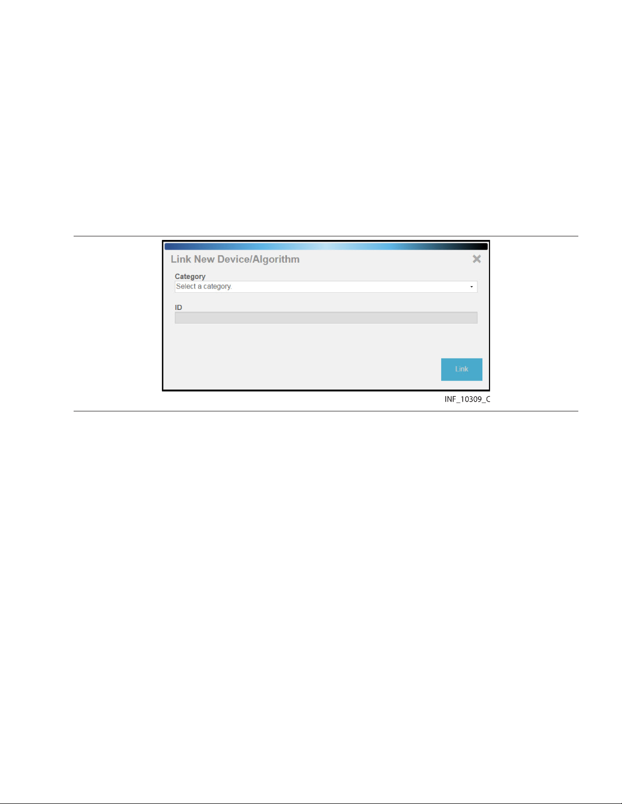
Note: When any automatic admission takes place, confirm that the patient physically present in the bed
is the patient indicated in the platform. Also, confirm that any devices physically linked to the patient are
the devices linked to that patient in the platform.
5.7.4 Link Additional Devices
Users can link more devices or algorithms to admitted patients using the same procedure used for the
first device or algorithm. (See Section 5.7.2, Manual Admission, page 76.)
Users also can link more devices to a patient directly from the Device Detail screen for that patient.
To link another device or algorithm to a patient from the Device Detail screen:
1. Click on the tile for the desired patient in the Tile View.
2. In the Device Detail screen, click on the blue Add Device icon in the patient header, near the top
right corner of the screen. A dialog for selecting a device will appear.
Figure 52. Link New Device/Algorithm dialog
3. Category—Select the desired device or algorithm category from the list of available categories.
4. ID—Select the desired device or algorithm from the drop-down list. Devices are listed by serial
number or network address, while algorithms are listed by name.
Note: Users at a monitoring station with a designated home area will only see available devices
accessible in the platform from within that area or its child areas.
5. Click Link to link the device or algorithm to the patient. The Device Detail screen will show data for
the device or algorithm just linked, as well as a system message describing the operation just
completed.
5.7.5 Manage Primary Devices
Users may designate a linked device as the primary device of that type for the patient.
The platform will show data from the primary device in places where data for only a single device can be
shown (for example, on a bed tile in the Tile View), unless the presence of active alarms or notifications
of higher priority on another linked device overrides this.
Also, alarms and notifications on the primary device have a higher priority in the platform than alarms
and notifications of the same priority on other linked devices. See Section 7.7, Event Priority, page 169.
Note: Designating a primary device is only possible when multiple devices of a particular type are linked
to the patient. If only one device of a particular type is linked to the patient, it is automatically the primary
device, and will remain the primary device if another device of the same type is subsequently linked to
the same patient (unless changed).
To make a linked device the primary device of its type:
80
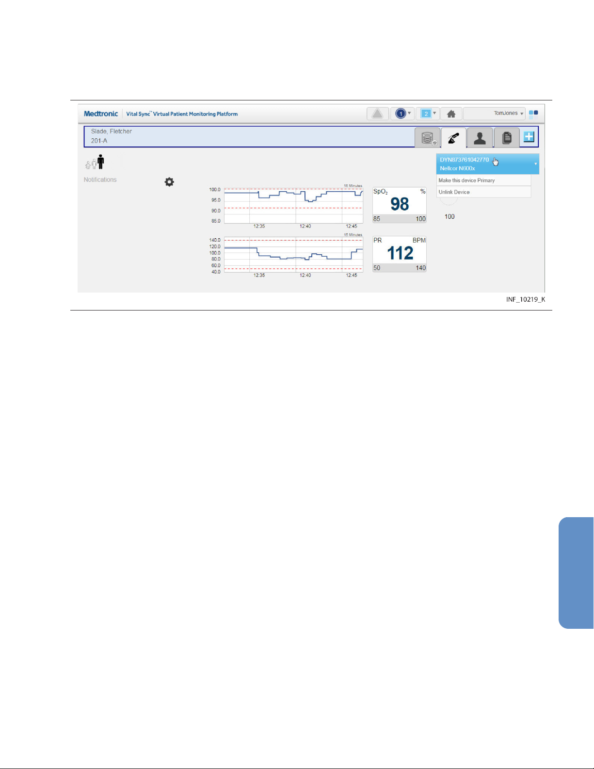
1. In the Tile View, click on the bed tile for the desired patient to access the Device Detail screen.
2. Show the device that is to be the primary device of its type by clicking on its tab in the patient
header.
3. Hover over the device button in the device header to access a drop-down menu. Figure 53. Device Detail Screen (making a device primary)
4. In the drop-down menu, select Make This Device Primary. The device currently shown will now
be designated as the primary device.
5.7.6 Device Connection Functions
Devices may occasionally lose communication with the software. The software allows devices to
automatically reconnect once able to communicate again. However, if the affected device has not
automatically reconnected, or has been out of communication for a longer period than the automatic
reconnection period set in the software, users may try to manually reestablish communication with
(relink) the affected device. They may also unlink a device entirely.
To relink a disconnected device or unlink a currently linked device, use the drop-down menu on the
device button in the Device Detail screen.
Note: The frequency with which devices lose communication will vary depending on the amount of data
being passed over the facility’s network, the specific configuration of the network, and on network
settings. Always check the actual device first, especially if difficulties with maintaining communication
are common or remain persistent. If there are no problems with the device, consult with facility IT
personnel or contact Medtronic (see Section 1.5, Obtaining Technical Assistance, page 14).
5.7.6.1 Relink a Device
If a device has lost communication, the bed tile and the device tab in the device header will show a
device disconnection icon.
If the device is selected in the Device Detail screen, the device panels will be blank, replaced by the
device disconnection icon. The date and time when communication was lost is also shown.
81

Figure 54. Device Detail Screen (device disconnected from the platform)
Both the bed tile and the Device Detail screen will also show a message with more detail on the type of
problem, as follows:
• Device Off—Both the platform and the device are able to communicate with the network, but no
device data is being received.
• Device Disconnected from Vital Sync—The platform is able to communicate with the network,
but the device is not visible on the network.
• Device Disconnected - Available to Reconnect—Both the platform and the device are able to
communicate with the network, and the device is available for relinking to the patient.
To attempt to relink a disconnected device in the Device Detail screen:
1. With the disconnected device selected, hover over the device button in the device header to
access connection functions.
2. Select Reconnect Device.
To attempt to relink a disconnected device in the Tile View:
1. Find the device tile for the disconnected device, ensuring that the serial number or identifier on the
device tile matches the serial number or identifier of the disconnected device.
2. Find the bed tile for the patient with the disconnected device. (If no alarms are active for devices
linked to this patient, the message “Device Disconnected – Available to Reconnect” will appear on
the bed tile.)
3. Drag the device tile for the disconnected device onto the bed tile.
If communication is reestablished, data for the device will appear, along with a system message (in blue)
indicating success. If communication cannot be reestablished, a system message (in red) will appear
indicating failure.
82
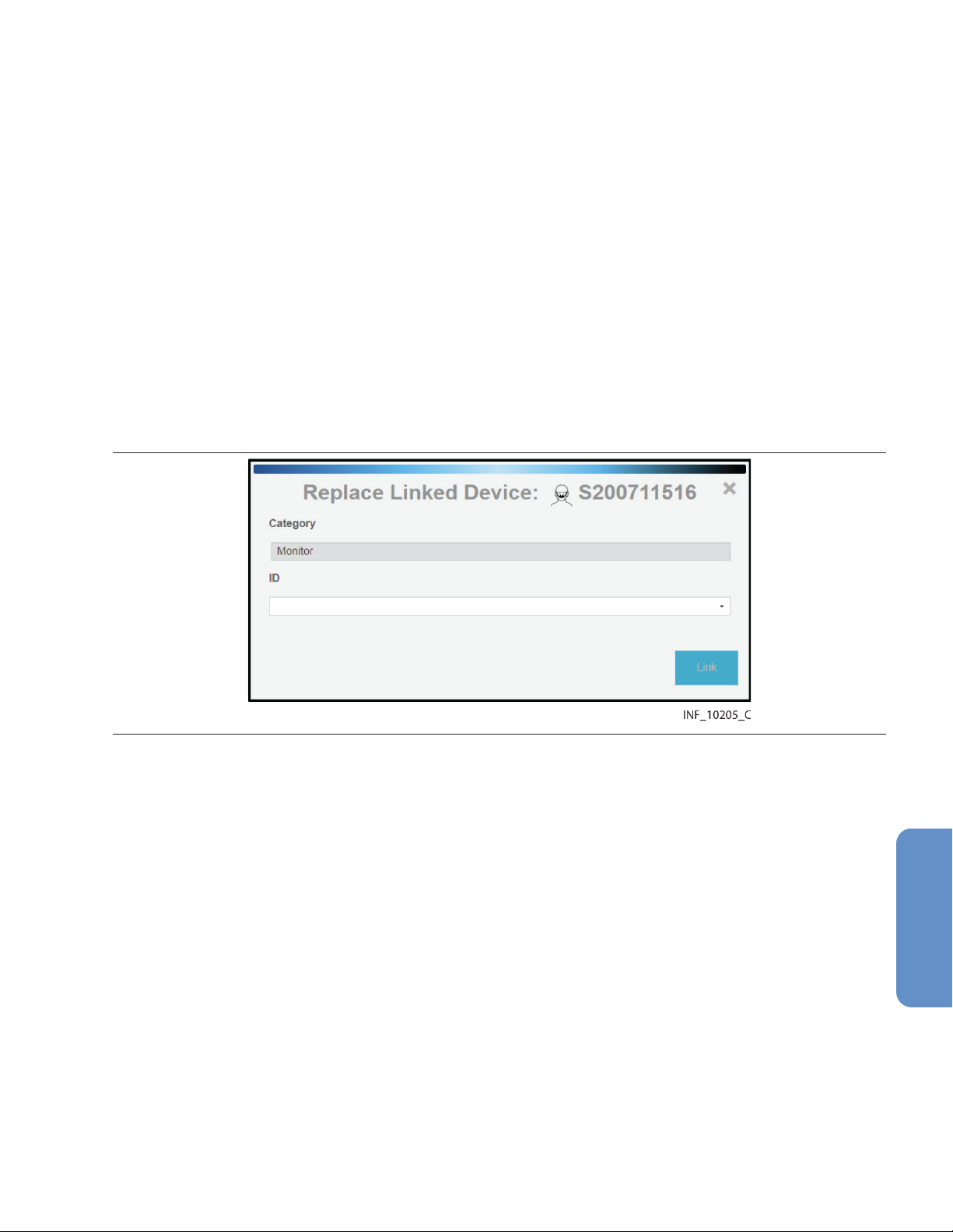
• Note: If the device has been disconnected for longer than the automatic reconnection interval set
in the software, it is possible to link the device to the patient multiple times, or for the device to have
already been linked to a different patient. To avoid these possibilities, unlink the device first.
• Note: Always check the actual device for problems if reconnecting is unsuccessful.
• Note: After linking the device to the patient in the platform, visually check the device itself to confirm
that the data it is showing also appears on the Device Detail screen for this patient.
• Note: If automatic discharge is enabled, and all of a patient’s linked devices are turned off at the
bedside, the patient will be discharged in the platform after a set time period. See Section 5.9.2,
Automated Discharge, page 86 for more information.
5.7.6.2 Replace a Device
Users may replace a currently linked device with another available device of the same type and model.
To replace a currently linked device:
1. With the desired device selected, hover over the device button in the device header to access
communication functions.
2. Select Replace Device. A dialog for selecting a device will appear. Figure 55. Replace Linked Device Dialog
3. Category—The appropriate category for the device being replaced automatically appears in this
field.
4. ID—Select the desired device from the drop-down list.
5. Click Link to link the new device.
Note: If the Replace Device option does not appear in the device button menu, there are no devices of
the same type and model available for linking. If an appropriate device of the same type (but a different
model) is available, link that device, then unlink the device being replaced.
5.7.6.3 Unlink a Device
When removing a device from a patient, the device also needs to be unlinked from the patient in the
platform.
To unlink a currently linked device:
1. With the desired device selected, hover over the device button in the device header to access
connection functions.
2. Select Unlink Device. A warning dialog will appear indicating that unlinking is a permanent
action; click Yes to continue with unlinking, or click No to abort and return to the Admit Patient
screen.
83

Once unlinked, a system message appears confirming that the device is no longer linked to this patient,
and data for the device will no longer appear on the Device Detail screen. Once the device is available
for linking, a tile representing the device will appear in the Tile View. (For information on how the platform
handles data collected on the device after unlinking, see Section 9.10, Device Data Handling After
Unlinking, page 190.)
Note: Unlinking a device from a patient only removes the link between the device and the patient within
the platform, stopping the platform from reporting data from that device. Unlinking does not affect or
control the functioning of the actual device in any way.
5.8 Manual Parameter Entry
If a derived parameter algorithm is activated and linked to a patient in the platform, users may need to
enter data manually in order to properly use the algorithm. For information on setting up and activating
algorithms in the platform, see Section 6.14, Manage Algorithms, page 153.
Clinicians, supervisors, link managers, and central monitoring stations may enter parameter data.
Bedside unit users cannot enter parameter data, since their access to device detail is view-only.
To enter parameter data manually:
1. Click on the tile for the desired patient to access the Device Detail screen.
2. If needed, click on the tab for the algorithm in the patient header to show algorithm information.
3. Click Enter Manual Parameters. A dialog will appear for entry of parameter data. (Available
fields in the dialog may or may not correspond directly to the parameters shown on the Device
Detail screen, depending on the algorithm.)
Note: Data and available manually-entered parameters are specific to the particular algorithm.
4. Make appropriate entries in parameter fields. When finished, click Save.
Once parameters are entered, if an alarm state is indicated for the patient according to the rules defined
in the algorithm, an alarm will annunciate in the platform according to rules and delay setting set up for
the algorithm.
If data for one or more parameters on which the algorithm is dependent is unavailable (for example, due
to disconnection of an associated device, or because the user has not entered manual parameter data),
a notification will appear indicating there is missing data, along with a time interval since the platform
received the most recent usable data.
If the algorithm is prevented from functioning at all, it will appear in the platform (after a certain period of
time) as a disconnected device.
• Note: Not all algorithms are designed to indicate an alarm state if particular conditions or
combinations of measured or manually entered parameters exist. Some algorithms will only
generate notifications in the platform.
• Note: If an algorithm is not functioning, the period of time before it appears in the platform user
interface as a disconnected device is dependent on the frequency with which the platform reports
algorithm data, and on the parameters involved. Generally, the more frequently the platform reports
algorithm data, the shorter the default period is before the algorithm appears as a disconnected
device.
• Note: Algorithm disconnection is typically an uncommon occurrence. It may be possible to
reconnect an algorithm, depending on how it is defined. Otherwise, assistance from facility IT
personnel or the Medtronic Solution Delivery Team may be required.
• Note: Algorithm parameters shown on the Device Detail screen or available for manual entry are
specific to each algorithm. Discussion of specific parameters, or the nature and frequency of
manual parameter entry, is beyond the scope of this manual. Consult with the Medtronic Solution
Delivery Team for details on setting up parameters and algorithms in the platform.
84

5.9 Discharge (Remove) a Patient
A patient who is no longer present in a bed must be discharged (removed from monitoring) in the
platform in order to make that bed available in the platform for other patients.
Manual discharge is available for any patient. Automated discharge is available for patients whose
linked devices are turned off at the bedside, or for patients who have had an HL7 discharge message
sent to the Vital Sync software.
Note: The discharge functionality removes the patient from monitoring in the platform. This functionality
is distinct from procedures or systems used to physically discharge the patient from the facility.
Note: The discharge functionality does not clear existing platform data pertaining to the patient
removed.
5.9.1 Manual Discharge
Clinicians, supervisors, link managers, and users at central monitoring stations may manually remove
patients at any time. Bedside unit users cannot manually remove patients, since their access to patient
detail is view only.
To remove a patient from a bed with currently associated devices:
1. In the Tile View, find the tile showing the patient to be removed.
2. Click on the tile to access the Device Detail screen.
3. Click on the Patient Detail tab on the right side of the patient header to access the patient
information fields.
4. Click Discharge Patient from System. A warning dialog will appear indicating that this action will
permanently remove the patient from the system.
5. Click Yes to confirm and return to the Tile View. The bed tile for the patient removed will now only
show the location ID and information for the bed’s associated devices. (Click No or click the X at
upper right in the dialog to return to the patient information fields without removing the patient.)
To remove a patient from a bed with no currently associated devices:
1. In the Tile View, find the tile showing the patient to be discharged. (The tile will be grey and will
show no device data or messages.)
2. Click on the tile to access the Device Detail screen. A message will appear indicating that the
patient currently has no linked devices, and the patient information fields will also appear.
85
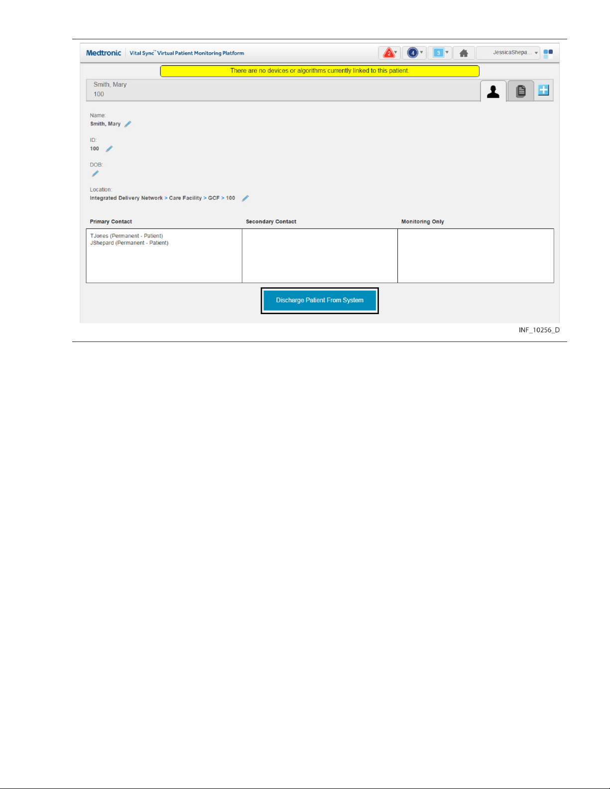
Figure 56. Device Detail Screen (manual discharge)
3. Click Discharge Patient from System. A warning dialog will appear indicating that this action will
remove the patient from the system.
4. Click Yes to confirm the discharge and return to the Tile View; the bed tile for the patient removed
will now be completely blank except for the location ID. (Click No or click the X at upper right in the
dialog to return to the patient information fields without discharging the patient.)
Note: A patient who has no linked devices remains visible and accessible in the platform (in the most
recent associated bed), in case devices need to be linked again later, or all existing device links need
to be replaced.
5.9.2 Automated Discharge
Automated discharge proceeds for eligible patients without intervention from any platform user.
Eligible patients include:
• If platform automatic discharge is enabled—Those whose linked devices are turned off at the
bedside and have not communicated with the platform beyond the set discharge time period.
• If ADT discharge functionality is configured—Those for whom the Vital Sync software has
received an HL7 discharge message.
To use platform automatic discharge, an administrative user must enable it and set the discharge time
period in an event rule set, then apply the rule set to one or more areas. See Section 6.11.4, Add or Edit
a Rule Set, page 141 and Section 6.8.1.3, Add or Edit an Area, page 130.
To use ADT discharge, an administrative user must add HL7 location information to beds in one or more
areas; see Section 6.8.2.3, Add or Edit a Bed, page 133. Integration with facility systems is also
required; consult with the Medtronic Solution Delivery Team for details.
86

• Note: Patients with devices out of communication for reasons other than being turned off at the
bedside will not be automatically discharged via the rule set for their area, even if devices are out
of communication beyond the discharge time period.
• Note: Patients with no associated devices will not be discharged via the rule set for their area.
Discharge patients with no associated devices manually.
• Note: Patients subject to automated discharge will remain visible and accessible in the platform
until discharged. Use the Rules and Settings dialog in the Device Detail screen to view the
discharge time period in use for the area in which a specific bed is located. See Section 5.5.8, View
Event Rules, page 72.
5.9.3 Patient Discharge History
The Patient Discharge History screen shows a list of the user’s assigned patients who were discharged
in the platform, either manually or automatically, within the last 24 hours.
Clinicians, supervisors, and central monitoring station users can access this screen.
To access the Patient Discharge History screen:
1. Hover over the navigation bar’s user function button to access the function menu.
2. Select Patient Discharge History.
Figure 57. Patient Discharge History Screen
The screen shows the following information for each patient listed:
• Time—The date and time of discharge
• Bed—The bed name
• Patient Name—The patient’s name
• Patient ID—The patient’s ID number in the platform
• Patient Discharged by—How the patient was discharged; options include:
– User—The patient was discharged by a platform user.
– ADT—The patient was discharged via ADT discharge functionality.
– Auto-Discharge—The patient was discharged via platform automatic discharge functionality.
Note: The list of patients shown is not a comprehensive list of all patients discharged for all users in the
previous 24 hours, but is a list of discharged patients assigned to the user viewing the Patient Discharge
History screen.
Note: The User designation indicates the patient was discharged by a user to whom that patient was
assigned. This can be the user currently viewing the list, or a different user to whom the patient was
assigned.
87

5.10 Patient Assignments
The Patient Assignment screen shows patients assigned to the current user, as well as all patients
currently linked to devices in the platform.
Clinicians can manage their patient assignments in this screen, while supervisors can manage their
own patient assignments and those of other users. Users at a central monitoring station can manage
that station’s patient assignments.
Patients selected will appear in the Tile View for the users to whom they are assigned. Assignments can
be permanent, or can be based on work shifts. Patients permanently assigned to a user will appear in
the platform at all times for that user, while patients assigned to a user for a particular shift will appear
during the hours of that shift.
Note: All patients in areas assigned to a user will automatically appear in the Tile View for that user,
unless changed in the Patient Assignment screen. (See Section 5.11, Area Assignments, page 94.)
To access the Patient Assignment screen:
1. Hover over the navigation bar’s user function button to access the function menu.
2. Select Patient Assignment.
Figure 58. Patient Assignment Screen
88

5.10.1 Availability by User Role
Clinicians, supervisors, link managers, and central monitoring station users can use all functions in the
Patient Assignment screen, as described in this section. Bedside unit users do not have access to this
screen.
5.10.2 Screen Layout
The Patient Assignment screen is divided into two panels, showing current assignments and patients
available for assignment.
The panel on the left (also called the left-side panel) contains tabs for different types of patient
assignments for a user. These include:
• Primary Contact tab—If there is an alarm or notification for any patient on this tab, this user is the
primary person to be contacted via Short Message Service (SMS) message or email.
• Secondary Contact tab—If there is an alarm or notification for any patient on this tab, this user is
a secondary person to be contacted via SMS message or email.
• Monitoring Only tab—If there is an alarm or notification for any patient on this tab, this user will not
be contacted via SMS message or email (the user is only assigned to monitor the patient, not
provide care).
Each tab shows a number denoting the number of patient assignments of that type for this user.
Tiles representing the patients assigned to the current user will appear on the tab on the left appropriate
to the assignment type. The number of patients assigned to the current user appears in parentheses
above the panel. (For supervisors, the number is in a drop-down menu.)
The panel on the right (also called the right-side panel) contains tiles showing either all patients currently
linked to devices in the platform or all patients currently unassigned to any user. In either case, the
number of patients in this column appears in parentheses in a drop-down menu above the panel.
If there are too many patients in a panel or a tab to be shown all at once, scroll bars will appear in that
panel or tab.
Each patient tile shows the patient’s room number, ID number and name.
Note: When initially accessed, the Patient Assignment screen shows the current user’s permanent
primary contact patient assignments in the left-side panel (on the Primary Contact tab), and all
patients currently linked to devices in the platform in the right-side panel.
Note: When initially accessed from a monitoring station that has a home area designated for it (see
Section 6.5.4, Edit a Monitoring Station Account, page 122), the patients shown in the right-side panel
will all be in beds assigned to that home area or its child areas.
5.10.3 Show Unassigned Patients
To show only patients who are not currently assigned to any users, click on the drop-down menu at the
top of the right-side panel and select Unassigned Patients.
89
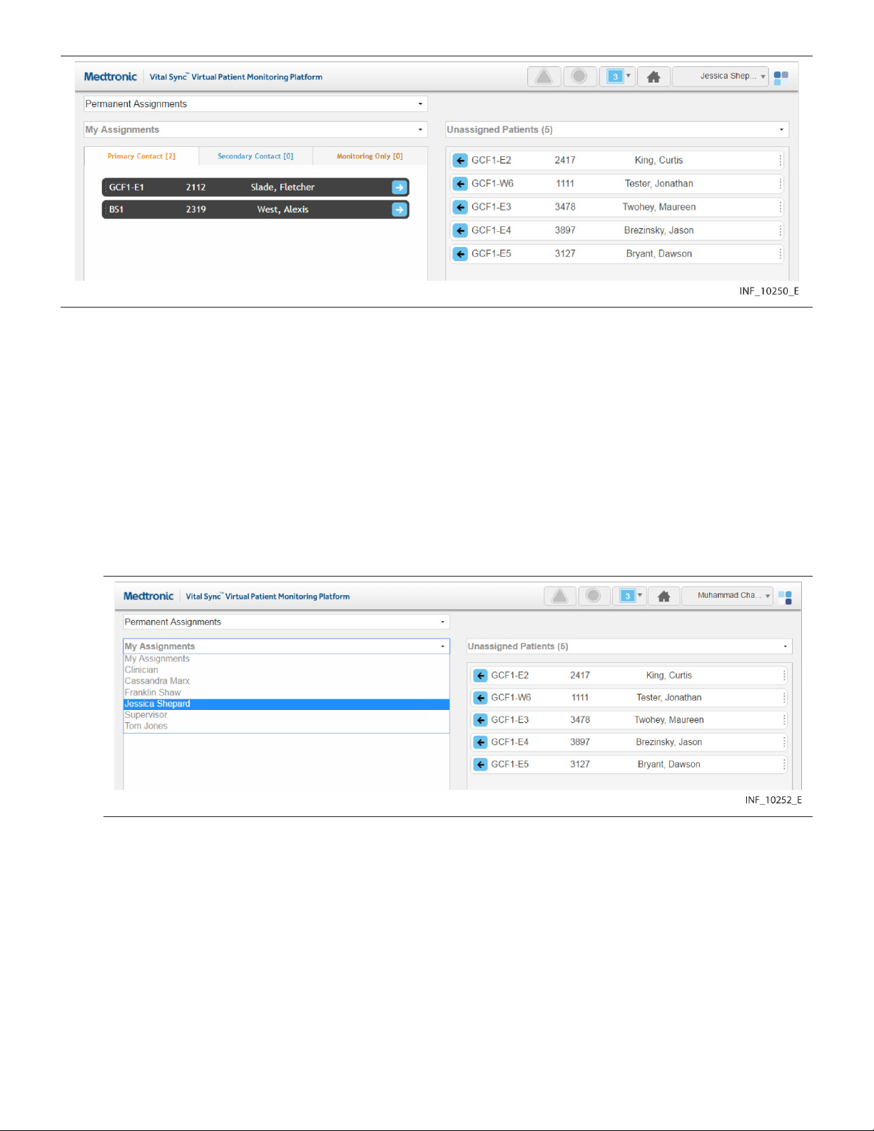
Figure 59. Patient Assignment Screen (unassigned patients shown)
Note: If viewing this screen from a monitoring station that has a designated home area, the only patients
that can be shown in the right-side panel are those in beds assigned to the home area and any child
areas. Other patients will not appear.
To once again show all patients in the right-side panel, click on the drop-down menu and select All
Patients.
5.10.4 Show Another User’s Assignments
Supervisors may show their own patients, or patients assigned to a different user.
To show patients assigned to another user:
1. Click on the drop-down menu at the top of the left-side panel. Figure 60. Patient Assignment Screen (other user selected)
2. Select the desired user from the list.
90
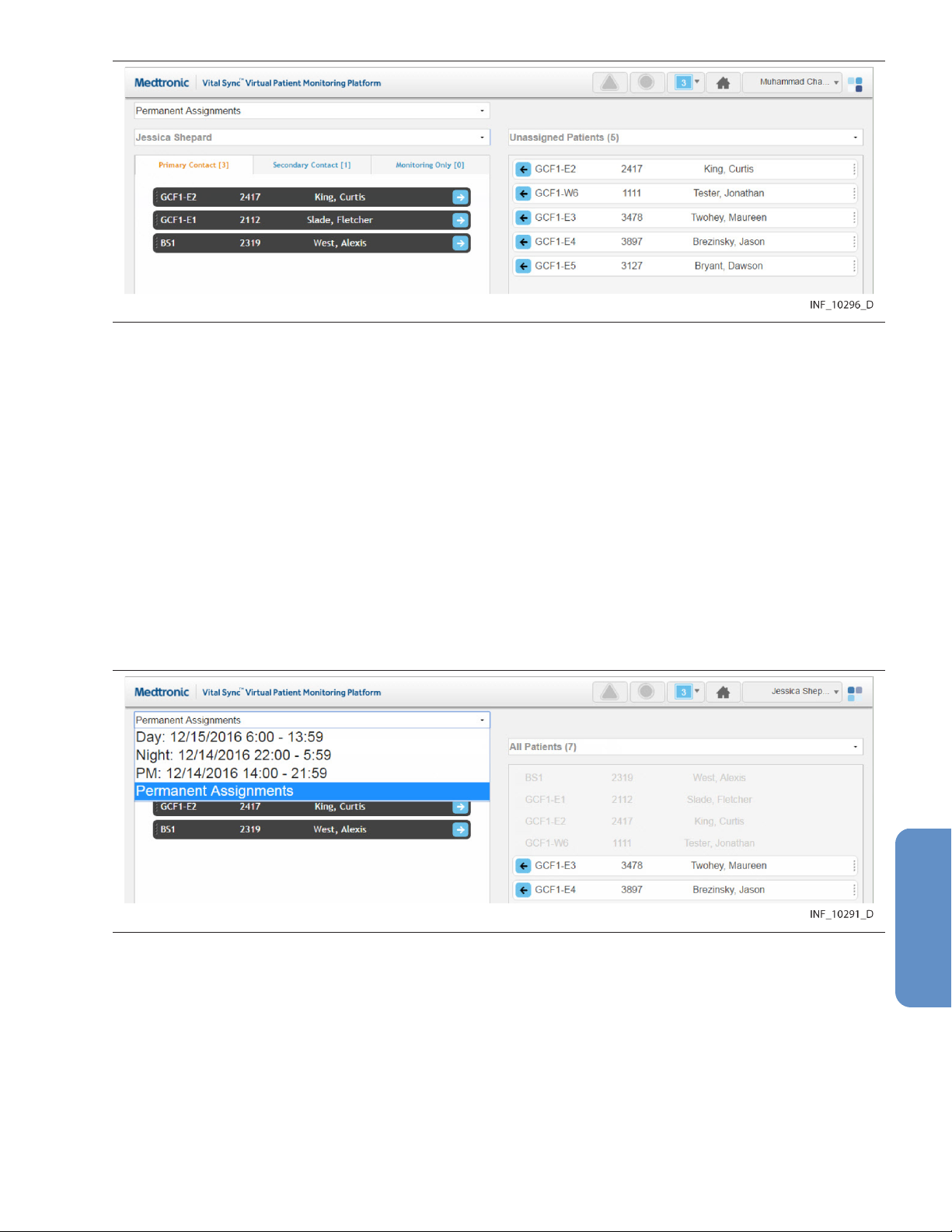
Figure 61. Patient Assignment Screen (other user’s assignments)
3. Patients to whom the desired user is assigned as a primary contact user will appear in the left-side
panel. To view other patient assignments, click on the Secondary Contact or Monitoring Only
tabs.
To once again show patients assigned to the current user in the left-side panel, click on the drop-down
menu and select My Assignments.
5.10.5 Show Assignments by Work Shift
Patient assignments can be permanent, or can be associated with a specific work shift. Patients
permanently assigned to a user will appear in the Tile View for that user at all times. Patients assigned
to a user during a specific shift will only appear in the Tile View for that user during that shift.
To show patient assignments for a specific work shift:
1. With the desired user selected, click in the drop-down menu at the top of the Patient Assignment
screen to show a list of work shifts available in the platform.
Figure 62. Patient Assignment Screen (shift menu shown)
2. Select the desired shift. The screen will show patients assigned to the currently selected user. If
the patient assignment is associated with the selected shift, it will appear in color; if not, the patient
assignment will appear in grey and will not be selectable.
For details on work shift setup, see Section 6.7, Manage Shifts, page 127.
Note: For added convenience, the date (relative to the current date) when each shift begins next is
shown in the drop-down list.
91

5.10.6 Change Patient Assignments
Clinicians can assign patients to themselves, change the assignment type for an assigned patient, or
remove their own patient assignments. Supervisors can perform all of these tasks, and also change
assignments for other users.
Note: Users viewing the platform from a central monitoring station can perform the same patient
assignment tasks as clinicians. However, the only patients available for assignment are those in the
designated home area for the station, or in any of that area’s child areas.
Assignments are of three types:
• Primary Contact—This user is the primary person to be contacted (via SMS message or email) if
there is an alarm or notification for this patient.
• Secondary Contact—This user is a secondary person to be contacted (via SMS message or
email) if there is an alarm or notification for this patient.
• Monitoring Only—This user is assigned only to monitor this patient, not to provide care, and will
not receive contact messages even if there is an alarm or notification for this patient.
5.10.6.1 Assign a Patient to a User
To assign a patient as a clinician or from a monitoring station:
1. Find the desired patient in the right-side panel. If needed, use the scroll bar to move up or down
the list. Any patient available for assignment will appear on a tile in color; patients already
assigned to this user (if any) will appear in grey and will not be selectable.
2. If the assignment should be permanent (not specific to a work shift), select Permanent
Assignments in the drop-down menu at the top of the screen (if not already selected). If the
assignment is only for a specific work shift, select the desired shift from the drop-down menu at the
top of the screen.
3. To assign the patient as a primary contact assignment, click the arrow on the left side of the tile for
the desired patient, or click on the Primary Assignment tab in the left-side panel and drag and drop
the patient tile into the left-side panel. To assign the patient as a secondary contact or
monitoring-only assignment, click on the appropriate tab in the left-side panel to open it, then drag
and drop the patient tile into the left-side panel.
To assign a patient as a supervisor:
1. Click on the drop-down menu at the top of the left-side panel.
2. If self-assigning the patient, select My Assigned Patients from the menu. If assigning the patient
to another user, select the name of the desired user from the menu. Patients assigned to the user
selected will appear in the left-side panel; primary assignments are shown by default.
3. Find the desired patient in the right-side panel. If needed, use the scroll bar to move up or down
the list. Any patient available for assignment will appear on a tile in color; patients (if any) already
assigned to the user currently shown will appear in grey and will not be selectable.
4. If the assignment should be permanent (not specific to a work shift), select Permanent
Assignments in the drop-down menu at the top of the screen (if not already selected). If the
assignment is only for a specific work shift, select the desired shift from the drop-down menu at the
top of the screen.
5. To assign the patient as a primary contact assignment, click the arrow on the left side of the tile for
the desired patient, or click on the Primary Assignment tab in the left-side panel and drag and drop
the patient tile into the left-side panel. To assign the patient as a secondary contact or
monitoring-only assignment, click on the appropriate tab in the left-side panel to open it, then drag
and drop the patient tile into the left-side panel.
92

5.10.6.2 Change a Patient Assignment Type
To change an assignment type as a clinician or from a monitoring station:
1. Find the desired patient in the left-side panel. If needed, click on a different assignment type tab
to open it; use the scroll bar to move up or down the list if there are more tiles than can be shown
in the tab.
2. Drag and drop the patient tile into the right-side panel.
3. Click on the tab for the desired assignment type in the left-side panel to open it.
4. Drag and drop the patient tile back into the left-side panel.
To change an assignment type as a supervisor:
1. Click on the drop-down menu at the top of the left-side panel.
2. Select either My Assignments (to show patients assigned to the current user) or the name of the
desired user (to show patients assigned to that user).
3. Find the desired patient in the left-side panel. If needed, click on a different assignment type tab
to open it; use the scroll bar to move up or down the list if there are more tiles than can be shown
in the tab.
4. Drag and drop the patient tile into the right-side panel.
5. Click on the tab for the desired assignment type in the left-side panel to open it.
6. Drag and drop the patient tile back into the left-side panel.
5.10.6.3 Remove Patient Assignments
To remove an assignment as a clinician or from a monitoring station:
1. Find the desired patient in the left-side panel. If needed, click on a different assignment type tab
to open it; use the scroll bar to move up or down the list if there are more tiles than can be shown
in the tab.
2. If the patient is assigned only during a specific work shift, select the appropriate shift from the
drop-down menu at the top of the screen. (Tiles for patients assigned during a specific shift will
appear in grey and cannot be selected unless that shift is selected first.)
3. Click the arrow on the right side of the tile for the desired patient, or drag and drop the tile into the
right-side panel.
To remove an assignment as a supervisor:
1. Click on the drop-down menu at the top of the left-side panel.
2. Select either My Assignments (to show patients assigned to the current user) or the name of the
desired user (to show patients assigned to that user).
3. Find the desired patient in the left-side panel. If needed, click a different assignment type tab to
open it, and use the scroll bar to move up or down the list.
4. If the patient is assigned only during a specific work shift, select the appropriate shift from the
drop-down menu at the top of the screen. (Tiles for patients assigned during a specific shift will
appear in grey and cannot be selected unless that shift is selected first.)
5. Click the arrow on the right side of the tile for the desired patient, or drag and drop the tile into the
right-side panel.
To remove all current assignments as a clinician or from a monitoring station:
1. If removing all permanent assignments, select Permanent Assignments in the drop-down menu
at the top of the screen. If removing all assignments for a specific work shift, select the desired shift
from the drop-down menu at the top of the screen. If removing assignments for a specific shift, the
93

tiles for patients assigned to the shift will appear in color, while tiles for permanently assigned
patients will appear in grey.
2. Click the Remove Assignments button. All tiles appearing in color will disappear from the
left-side panel, and will now appear in color in the “All Patients” view in the right-side panel. The
numbers on each tab in the left-side panel will all change to zero, indicating no patients are
assigned.
To remove all current assignments for a user or a monitoring station as a supervisor:
1. Click on the drop-down menu at the top of the left-side panel.
2. If removing all assignments for the current user, select My Assignments from the list; if removing
all assignments for another user, select the desired user from the list. The screen will show the
patients assigned to the selected user.
3. If removing all permanent assignments, select Permanent Assignments in the drop-down menu
at the top of the screen. If removing all assignments for a specific work shift, select the desired shift
from the drop-down menu at the top of the screen. If removing assignments for a specific shift, the
tiles for patients assigned to the shift will appear in color, while tiles for permanently assigned
patients will appear in grey.
4. Click the Remove Assignments button. All tiles appearing in color will disappear from the
left-side panel, and will now appear in color in the “All Patients” view in the right-side panel. The
numbers on the tabs in the left-side panel will all change to zero, indicating no patients are
assigned.
Note: Changes to patient assignments only affect the currently selected user or monitoring station.
Patients shown in either panel of the Patient Assignment screen may also already be assigned to other
users.
5.11 Area Assignments
The Area Assignment screen shows areas in the facility (sometimes also referred to as zones or areas
of care) to which the current user is assigned, as well as areas with no assigned users or all areas set
up in the platform.
Clinicians can manage their area assignments in this screen, while supervisors can manage their own
area assignments and those of other users. Users at a central monitoring station can manage that
station’s area assignments, within home area limits.
All patients in areas selected in this screen will appear in the platform for any user to whom the area is
assigned, unless specifically unassigned from that user. Area assignments can be permanent, or can
be based on work shifts; in the latter case, patients in a particular area will appear to users to whom the
area is assigned during those users’ work shifts.
Note: When an area is assigned to a user, all patients in that area are initially assigned to that user. To
remove specific individual patient assignments after assigning the area, use the Patient Assignment
screen. (See Section 5.10, Patient Assignments, page 88.) Also, a user to whom an area is assigned will
not see, in the Tile View, available devices assigned to other areas without adjusting the view to see all
available devices (see Section 5.4.4, Additional Tile View Functions, page 52 for details).
To access the Area Assignment screen:
1. Hover over the navigation bar’s user function button to access the function menu.
2. Select Area Assignment.
94
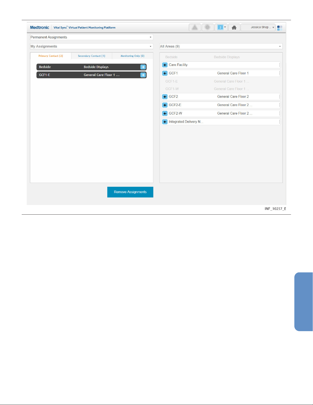
Figure 63. Area Assignment Screen
5.11.1 Availability by User Role
Clinicians, supervisors, link managers, and central monitoring station users can use all functions in the
Area Assignment screen, as described in this section. Bedside unit users do not have access to this
screen.
5.11.2 Screen Layout
The Area Assignment screen is divided into two panels, showing current assignments and areas
available for assignment.
The panel on the left (also called the left-side panel) contains tabs for different types of area
assignments for a user. These include:
• Primary Contact tab—If there is an alarm or notification for any patient on this tab, this user is the
primary person to be contacted via Short Message Service (SMS) message or email.
• Secondary Contact tab—If there is an alarm or notification for any patient on this tab, this user is
a secondary person to be contacted via SMS message or email.
• Monitoring Only tab—If there is an alarm or notification for any patient on this tab, this user will not
be contacted via SMS message or email (the user is only assigned to monitor the area, not provide
care to patients).
Note: For an SMS message or email to be sent to a user to whom an area is assigned, the patient
associated with the alarm or notification triggering the SMS message or email also has to be assigned
to that user.
95
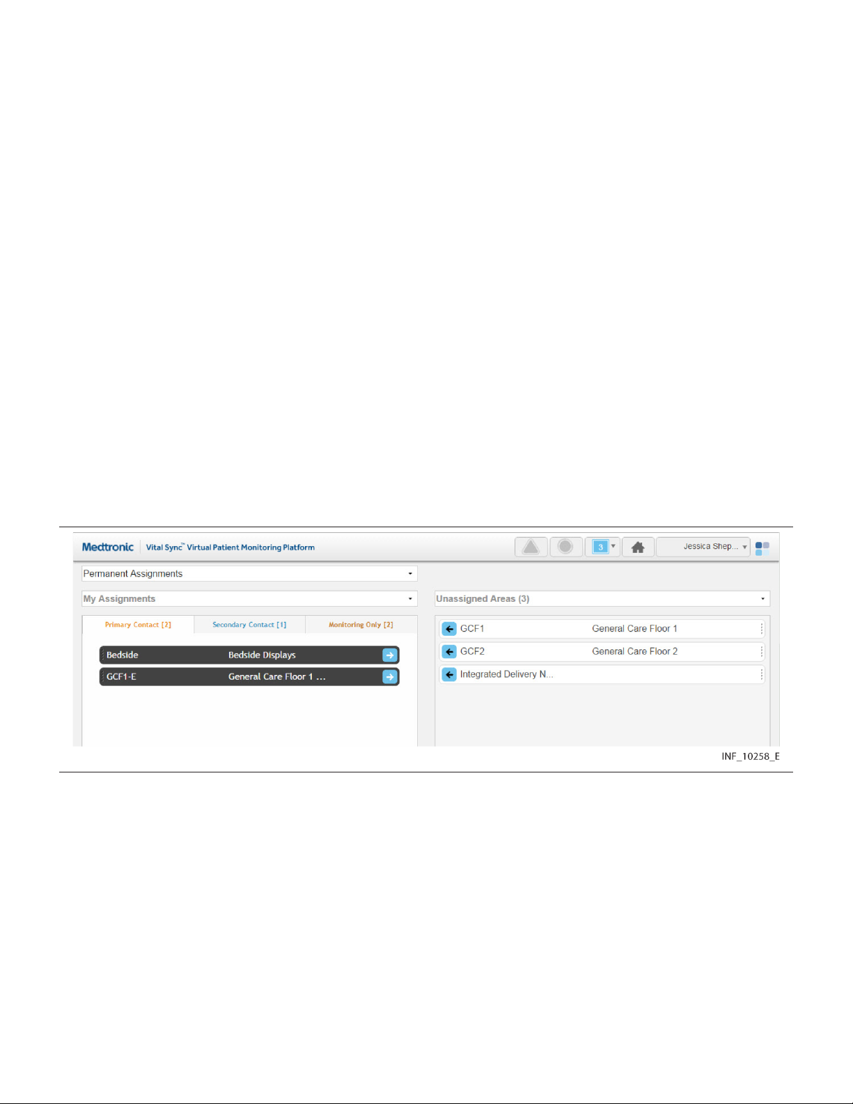
Each tab shows a number denoting the number of area assignments of that type for this user.
Tiles representing the areas to which the user currently shown is assigned will appear in the tab on the
left appropriate to the assignment type. The number of areas assigned to the user appears in
parentheses above the panel. (For supervisors, the number is in a drop-down menu.)
The panel on the right (also called the right-side panel) contains tiles showing either all areas set up in
the platform or just the areas to which the current user is not assigned. In either case, the number of
areas shown in this column appears in parentheses in a drop-down menu above the panel.
If there are too many areas in a panel (or a pane within a panel) to be shown on a single screen, scroll
bars will appear in that panel or pane.
Each area tile shows the area identifier and description.
Note: When initially accessed, the Area Assignment screen shows the current user’s permanent
primary contact area assignments in the left-side panel (on the Primary Contact tab), and all areas in the
platform in the right-side panel.
Note: When initially accessed from a monitoring station that has a home area designated for it (see
Section 6.5.4, Edit a Monitoring Station Account, page 122), the only areas shown in the right-side
panel will be the designated home area and its child areas. The designated home area’s name on the
area tile will appear in brackets.
5.11.3 Show Unassigned Areas
To show only areas not currently assigned to any users, click on the drop-down menu at the top of the
right-side panel and select Unassigned Areas.
Figure 64. Area Assignment Screen (unassigned areas shown)
Note: If viewing this screen from a monitoring station that has a designated home area, the only areas
that can be shown in the right-side panel are the home area (denoted by brackets around its name on
the area tile) and any child areas. Other areas will not appear.
To once again show all areas in the right-side panel, click on the drop-down menu and select All Areas.
5.11.4 Show Another User’s Assignments
The default listing in the left-side panel is of the areas currently assigned to the current user. Supervisors
may also view areas to which a different user is assigned.
To show the areas to which another user is assigned:
1. Click on the drop-down menu at the top of the left-side panel.
96

Figure 65. Area Assignment Screen (other user selected)
2. Select the desired user from the list. Figure 66. Area Assignment Screen (other user’s assignments)
To once again show areas assigned to the current user in the left-side panel, click on the drop-down
menu and select My Assignments.
5.11.5 Show Assignments by Work Shift
Area assignments can be permanent, or can be associated with a specific work shift. Patients in areas
permanently assigned to a user will appear in the Tile View for that user at all times. Patients in areas
assigned to a user during a specific shift will only appear in the Tile View for that user during that shift.
To show area assignments for a specific work shift:
1. With the desired user selected, click in the field at the top of the Area Assignment screen to show
a list of work shifts defined in the platform.
97
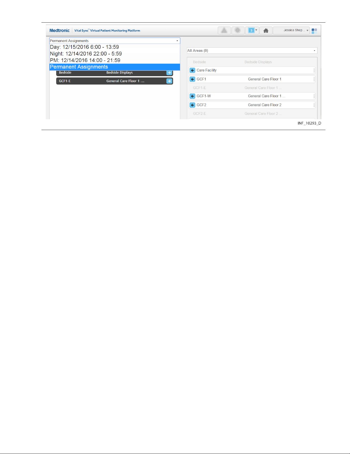
Figure 67. Area Assignment Screen (shift menu shown)
2. Select the desired shift. The left-side panel will show areas assigned to the currently selected
user. If the area assignment is associated with the currently selected shift, it will appear on a tile
in color; if not, the area assignment will appear in grey and will not be selectable.
For details on work shift setup, see Section 6.7, Manage Shifts, page 127.
Note: For added convenience, the date (relative to the current date) when each shift begins next is
shown in the drop-down list.
5.11.6 Change Area Assignments
Clinicians can assign areas to themselves and remove their own area assignments. Supervisors can
perform both these tasks for themselves and for other users, and can also change assignment types.
Note: Users viewing the platform from a central monitoring station can perform the same area
assignment tasks as clinicians. However, if the station has a home area designated for it, the only areas
available for assignment are the home area and any of its child areas.
Assignments are of three types:
• Primary Contact—This user is the primary person to be contacted (via SMS message or email) if
there is an alarm or notification for a patient in this area and assigned to this user.
• Secondary Contact—This user is a secondary person to be contacted (via SMS message or
email) if there is an alarm or notification for a patient in this area and assigned to this user.
• Monitoring Only—This user only monitors patients, and will not receive contact messages even if
there is an alarm or notification for a patient in this area who is assigned to this user.
5.11.6.1 Assign an Area to a User
To assign an area as a clinician or from a monitoring station:
1. Find the desired area in the right-side panel. If needed, use the scroll bar to move up or down the
list.
Note: If viewing this screen from a monitoring station, the area name on the tile for the station’s
designated home area will appear in brackets.
2. If this assignment should be permanent (not specific to a work shift), select Permanent
Assignments in the drop-down menu at the top of the screen (if not already selected). If this
assignment is only for a specific work shift, select the desired shift from the drop-down menu at the
top of the screen.
3. To assign the area as a primary contact assignment, click the arrow on the left side of the tile for
the desired area, or click the Primary Assignment tab in the left-side panel and drag and drop the
98

area tile into the left-side panel. To assign the area as a secondary contact or monitoring-only
assignment, click on the appropriate tab in the left-side panel to open it, then drag and drop the
area tile into the left-side panel.
To assign an area as a supervisor:
1. Click on the drop-down menu at the top of the left-side panel.
2. If self-assigning the area, select My Assignments. If assigning the area to another user, select
the name of the desired user from the menu. Areas assigned to the user selected will appear in the
left-side panel; primary assignments are shown by default.
3. Find the desired area in the right-side panel. If needed, use the scroll bar to move up or down the
list. Any area available for assignment will appear on a tile in color; areas already assigned to the
user currently shown (if any) will appear in grey and will not be selectable.
4. If the assignment should be permanent (not specific to a work shift), select Permanent
Assignments in the drop-down menu at the top of the screen (if not already selected). If this
assignment is only for a specific work shift, select the desired shift from the drop-down menu at the
top of the screen.
5. To assign the area as a primary contact assignment, click the arrow on the left side of the tile for
the desired area, or click on the Primary Assignment tab in the left-side panel and drag and drop
the area tile into the left-side panel. To assign the area as a secondary contact or monitoring-only
assignment, click on the appropriate tab in the left-side panel to open it, then drag and drop the
area tile into the left-side panel.
5.11.6.2 Change an Area Assignment Type
To change an assignment type as a clinician or from a monitoring station:
1. Find the desired area in the left-side panel. If needed, click on a different assignment type tab to
open it; use the scroll bar to move up or down the list if there are more tiles than can be shown in
the tab.
2. Drag and drop the area tile into the right-side panel.
3. Click on the tab for the desired assignment type in the left-side panel to open it.
4. Drag and drop the area tile back into the left-side panel.
To change an assignment type as a supervisor:
1. Click on the drop-down menu at the top of the left-side panel.
2. Select either My Assignments (to show areas assigned to the current user) or the name of the
desired user (to show areas assigned to that user).
3. Find the desired area in the left-side panel. If needed, click on a different assignment type tab to
open it; use the scroll bar to move up or down the list if there are more tiles than can be shown in
the tab.
4. Drag and drop the area tile into the right-side panel.
5. Click on the tab for the desired assignment type in the left-side panel to open it.
6. Drag and drop the area tile back into the left-side panel.
5.11.6.3 Remove Area Assignments
To remove an assignment as a clinician or from a monitoring station:
1. Find the desired area in the left-side panel. If needed, click on a different assignment type tab to
open it; use the scroll bar to move up or down the list if there are more tiles than can be shown in
the tab.
99

2. If the area is assigned only during a specific work shift, select the appropriate shift from the
drop-down menu at the top of the screen. (Tiles for areas assigned during a specific shift will
appear in grey and cannot be selected unless that shift is selected first.)
3. Click the arrow on the right side of the tile for the desired patient, or drag and drop the tile into the
right-side panel.
To remove an assignment as a supervisor:
1. Click on the drop-down menu at the top of the left-side panel.
2. Select either My Assignments (to show the areas assigned to the current user) or the name of the
desired user (to show areas assigned to that user).
3. Find the desired area in the left-side panel. If needed, use the scroll bar to move up or down the
list.
4. If the area is assigned only during a specific work shift, select the appropriate shift from the
drop-down menu at the top of the screen. (Tiles for areas assigned during a specific shift will
appear in grey and cannot be selected unless that shift is selected first.)
5. Click the arrow on the right side of the tile for the desired area, or drag and drop the tile into the
right-side panel.
To remove all current assignments as a clinician or from a monitoring station:
1. If removing all permanent assignments, select Permanent Assignments in the drop-down menu
at the top of the screen. If removing all assignments for a specific work shift, select the desired shift
from the drop-down menu at the top of the screen. If removing assignments for a specific shift, the
tiles for areas assigned during this shift will appear in color, while tiles for permanently assigned
areas will appear in grey.
2. Click the Remove Assignments button. All tiles appearing in color will disappear from the
left-side panel, and will now appear in color in the “All Areas” view in the right-side panel. The
numbers on the tabs in the left-side panel will all change to zero, indicating no areas are assigned.
To remove all current area assignments for a user as a supervisor:
1. Click on the drop-down menu at the top of the left-side panel.
2. If removing all assignments for the current user, select My Assignments from the list; if removing
all assignments for another user, select the desired user from the list. The screen will show the
areas assigned to the selected user.
3. If removing all permanent assignments, select Permanent Assignments in the drop-down menu
at the top of the screen. If removing all assignments for a specific work shift, select the desired shift
from the drop-down menu at the top of the screen. If removing assignments for a specific shift, the
tiles for areas assigned during this shift will appear in color, while tiles for permanently assigned
areas will appear in grey.
4. Click the Remove Assignments button. All tiles appearing in color will disappear from the
left-side panel, and will now appear in color in the “All Areas” view in the right-side panel. The
numbers on the tabs in the left-side panel will all change to zero, indicating no areas are assigned.
Note: Removing an area assignment will unassign patients in that area from the user, unless the patient
in question has been specifically assigned to the user in the Patient Assignment screen.
Note: Changes to area assignments only affect the currently selected user or monitoring station. Areas
shown in either panel of the Area Assignment screen may also already be assigned to other users.
5.12 Select User Mode
In addition to their own functions, supervisors can use the Select User mode to view and use the
platform as if logged in as a specific clinician, or viewing the platform from a specific monitoring station.
100
 Loading...