


Vital Sync™
Virtual Patient Monitoring Platform and Informatics Manager
Reference Manual

U.S. patents: www.medtronic.com/patents
Medtronic and Medtronic logo are trademarks of Medtronic. ™* brands are trademarks of their respective owner.
Other brands are trademarks of a Medtronic company.

Symbols
Federal (U.S.A.) law restricts the use of the application to sale by or on the order of a physician.
Consult instructions for use.
Manufacturer.
i

ii

Table of Contents
1 Introduction . . . . . . . . . . . . . . . . . . . . . . . . . . . . . . . . . . . . . . . . . . . . . . . . . . . . . . . . . . . . . . . . . . . . . . . . . . . . 9
Overview . . . . . . . . . . . . . . . . . . . . . . . . . . . . . . . . . . . . . . . . . . . . . . . . . . . . . . . . . . . . . . . . . . . . . . . . . . . . 9
Conventions . . . . . . . . . . . . . . . . . . . . . . . . . . . . . . . . . . . . . . . . . . . . . . . . . . . . . . . . . . . . . . . . . . . . . . . . . 9
Applicable Version . . . . . . . . . . . . . . . . . . . . . . . . . . . . . . . . . . . . . . . . . . . . . . . . . . . . . . . . . . . . . . . . . 10
Safety Information . . . . . . . . . . . . . . . . . . . . . . . . . . . . . . . . . . . . . . . . . . . . . . . . . . . . . . . . . . . . . . . . . 10
Obtaining Technical Assistance . . . . . . . . . . . . . . . . . . . . . . . . . . . . . . . . . . . . . . . . . . . . . . . . . . . . . 12
Warranty Information . . . . . . . . . . . . . . . . . . . . . . . . . . . . . . . . . . . . . . . . . . . . . . . . . . . . . . . . . . . . . . 12
Licensing Information . . . . . . . . . . . . . . . . . . . . . . . . . . . . . . . . . . . . . . . . . . . . . . . . . . . . . . . . . . . . . . 12
HIPAA Disclaimer . . . . . . . . . . . . . . . . . . . . . . . . . . . . . . . . . . . . . . . . . . . . . . . . . . . . . . . . . . . . . . . . . . 13
2 Product Overview . . . . . . . . . . . . . . . . . . . . . . . . . . . . . . . . . . . . . . . . . . . . . . . . . . . . . . . . . . . . . . . . . . . . 15
Overview . . . . . . . . . . . . . . . . . . . . . . . . . . . . . . . . . . . . . . . . . . . . . . . . . . . . . . . . . . . . . . . . . . . . . . . . . . 15
Intended Use . . . . . . . . . . . . . . . . . . . . . . . . . . . . . . . . . . . . . . . . . . . . . . . . . . . . . . . . . . . . . . . . . . . . . . 15
User Interface Overview . . . . . . . . . . . . . . . . . . . . . . . . . . . . . . . . . . . . . . . . . . . . . . . . . . . . . . . . . . . . 15
User Interface Symbols . . . . . . . . . . . . . . . . . . . . . . . . . . . . . . . . . . . . . . . . . . . . . . . . . . . . . . . . . . . . . 18
Device Types Supported . . . . . . . . . . . . . . . . . . . . . . . . . . . . . . . . . . . . . . . . . . . . . . . . . . . . . . . . . . . 23
3 Installation and Access . . . . . . . . . . . . . . . . . . . . . . . . . . . . . . . . . . . . . . . . . . . . . . . . . . . . . . . . . . . . . . . . 25
Overview . . . . . . . . . . . . . . . . . . . . . . . . . . . . . . . . . . . . . . . . . . . . . . . . . . . . . . . . . . . . . . . . . . . . . . . . . . 25
System Requirements . . . . . . . . . . . . . . . . . . . . . . . . . . . . . . . . . . . . . . . . . . . . . . . . . . . . . . . . . . . . . . 25
Installation . . . . . . . . . . . . . . . . . . . . . . . . . . . . . . . . . . . . . . . . . . . . . . . . . . . . . . . . . . . . . . . . . . . . . . . . 25
Access . . . . . . . . . . . . . . . . . . . . . . . . . . . . . . . . . . . . . . . . . . . . . . . . . . . . . . . . . . . . . . . . . . . . . . . . . . . . . 25
Login . . . . . . . . . . . . . . . . . . . . . . . . . . . . . . . . . . . . . . . . . . . . . . . . . . . . . . . . . . . . . . . . . . . . . . . . . . . . . . 26
4 Clinician and Supervisor Operation . . . . . . . . . . . . . . . . . . . . . . . . . . . . . . . . . . . . . . . . . . . . . . . . . . . . 27
Overview . . . . . . . . . . . . . . . . . . . . . . . . . . . . . . . . . . . . . . . . . . . . . . . . . . . . . . . . . . . . . . . . . . . . . . . . . . 27
Alarms and Notifications . . . . . . . . . . . . . . . . . . . . . . . . . . . . . . . . . . . . . . . . . . . . . . . . . . . . . . . . . . . 27
Navigation and Basic User Interface . . . . . . . . . . . . . . . . . . . . . . . . . . . . . . . . . . . . . . . . . . . . . . . . 27
Tile View (Patient Overview Screen) . . . . . . . . . . . . . . . . . . . . . . . . . . . . . . . . . . . . . . . . . . . . . . . . 31
Device Detail Screen . . . . . . . . . . . . . . . . . . . . . . . . . . . . . . . . . . . . . . . . . . . . . . . . . . . . . . . . . . . . . . . 36
All Patients and Devices Screen . . . . . . . . . . . . . . . . . . . . . . . . . . . . . . . . . . . . . . . . . . . . . . . . . . . . . 55
Patient and Device Links . . . . . . . . . . . . . . . . . . . . . . . . . . . . . . . . . . . . . . . . . . . . . . . . . . . . . . . . . . . 57
Manual Parameter Entry . . . . . . . . . . . . . . . . . . . . . . . . . . . . . . . . . . . . . . . . . . . . . . . . . . . . . . . . . . . . 64
Discharge (Remove) a Patient . . . . . . . . . . . . . . . . . . . . . . . . . . . . . . . . . . . . . . . . . . . . . . . . . . . . . . 65
Patient Assignments . . . . . . . . . . . . . . . . . . . . . . . . . . . . . . . . . . . . . . . . . . . . . . . . . . . . . . . . . . . . . . . 67
Area Assignments . . . . . . . . . . . . . . . . . . . . . . . . . . . . . . . . . . . . . . . . . . . . . . . . . . . . . . . . . . . . . . . . . . 73
Select User Mode . . . . . . . . . . . . . . . . . . . . . . . . . . . . . . . . . . . . . . . . . . . . . . . . . . . . . . . . . . . . . . . . . . 79
Event List . . . . . . . . . . . . . . . . . . . . . . . . . . . . . . . . . . . . . . . . . . . . . . . . . . . . . . . . . . . . . . . . . . . . . . . . . . 80
Reports . . . . . . . . . . . . . . . . . . . . . . . . . . . . . . . . . . . . . . . . . . . . . . . . . . . . . . . . . . . . . . . . . . . . . . . . . . . . 82
Change Password . . . . . . . . . . . . . . . . . . . . . . . . . . . . . . . . . . . . . . . . . . . . . . . . . . . . . . . . . . . . . . . . . . 82
Audible Alerts . . . . . . . . . . . . . . . . . . . . . . . . . . . . . . . . . . . . . . . . . . . . . . . . . . . . . . . . . . . . . . . . . . . . . 83
Help . . . . . . . . . . . . . . . . . . . . . . . . . . . . . . . . . . . . . . . . . . . . . . . . . . . . . . . . . . . . . . . . . . . . . . . . . . . . . . . 85
Version Information . . . . . . . . . . . . . . . . . . . . . . . . . . . . . . . . . . . . . . . . . . . . . . . . . . . . . . . . . . . . . . . . 85
Platform Logout . . . . . . . . . . . . . . . . . . . . . . . . . . . . . . . . . . . . . . . . . . . . . . . . . . . . . . . . . . . . . . . . . . . 86
5 Administrator Operation . . . . . . . . . . . . . . . . . . . . . . . . . . . . . . . . . . . . . . . . . . . . . . . . . . . . . . . . . . . . . . 87
Overview . . . . . . . . . . . . . . . . . . . . . . . . . . . . . . . . . . . . . . . . . . . . . . . . . . . . . . . . . . . . . . . . . . . . . . . . . . 87
Navigation and Basic User Interface . . . . . . . . . . . . . . . . . . . . . . . . . . . . . . . . . . . . . . . . . . . . . . . . 87
Administrative Home Screen . . . . . . . . . . . . . . . . . . . . . . . . . . . . . . . . . . . . . . . . . . . . . . . . . . . . . . . 88
Reference Manual English 1

Manage Users . . . . . . . . . . . . . . . . . . . . . . . . . . . . . . . . . . . . . . . . . . . . . . . . . . . . . . . . . . . . . . . . . . . . . 90
Manage Bedside Display Users . . . . . . . . . . . . . . . . . . . . . . . . . . . . . . . . . . . . . . . . . . . . . . . . . . . . . 99
Manage Shifts . . . . . . . . . . . . . . . . . . . . . . . . . . . . . . . . . . . . . . . . . . . . . . . . . . . . . . . . . . . . . . . . . . . . 102
Manage Locations . . . . . . . . . . . . . . . . . . . . . . . . . . . . . . . . . . . . . . . . . . . . . . . . . . . . . . . . . . . . . . . . 104
Manage Device Inventory . . . . . . . . . . . . . . . . . . . . . . . . . . . . . . . . . . . . . . . . . . . . . . . . . . . . . . . . . 109
Device Status . . . . . . . . . . . . . . . . . . . . . . . . . . . . . . . . . . . . . . . . . . . . . . . . . . . . . . . . . . . . . . . . . . . . . 111
Manage Alarm, Notification, and Setting Rules . . . . . . . . . . . . . . . . . . . . . . . . . . . . . . . . . . . . . 114
Manage Alerts . . . . . . . . . . . . . . . . . . . . . . . . . . . . . . . . . . . . . . . . . . . . . . . . . . . . . . . . . . . . . . . . . . . . 123
Manage Parameters . . . . . . . . . . . . . . . . . . . . . . . . . . . . . . . . . . . . . . . . . . . . . . . . . . . . . . . . . . . . . . . 126
Manage Algorithms . . . . . . . . . . . . . . . . . . . . . . . . . . . . . . . . . . . . . . . . . . . . . . . . . . . . . . . . . . . . . . . 127
Reports . . . . . . . . . . . . . . . . . . . . . . . . . . . . . . . . . . . . . . . . . . . . . . . . . . . . . . . . . . . . . . . . . . . . . . . . . . . 129
Help . . . . . . . . . . . . . . . . . . . . . . . . . . . . . . . . . . . . . . . . . . . . . . . . . . . . . . . . . . . . . . . . . . . . . . . . . . . . . . 130
Version Information . . . . . . . . . . . . . . . . . . . . . . . . . . . . . . . . . . . . . . . . . . . . . . . . . . . . . . . . . . . . . . . 130
Platform Logout . . . . . . . . . . . . . . . . . . . . . . . . . . . . . . . . . . . . . . . . . . . . . . . . . . . . . . . . . . . . . . . . . . 130
6 Reports . . . . . . . . . . . . . . . . . . . . . . . . . . . . . . . . . . . . . . . . . . . . . . . . . . . . . . . . . . . . . . . . . . . . . . . . . . . . . 133
Overview . . . . . . . . . . . . . . . . . . . . . . . . . . . . . . . . . . . . . . . . . . . . . . . . . . . . . . . . . . . . . . . . . . . . . . . . . 133
Access . . . . . . . . . . . . . . . . . . . . . . . . . . . . . . . . . . . . . . . . . . . . . . . . . . . . . . . . . . . . . . . . . . . . . . . . . . . . 133
Report Functions . . . . . . . . . . . . . . . . . . . . . . . . . . . . . . . . . . . . . . . . . . . . . . . . . . . . . . . . . . . . . . . . . 134
Administrative Reports . . . . . . . . . . . . . . . . . . . . . . . . . . . . . . . . . . . . . . . . . . . . . . . . . . . . . . . . . . . . 137
Clinician Reports . . . . . . . . . . . . . . . . . . . . . . . . . . . . . . . . . . . . . . . . . . . . . . . . . . . . . . . . . . . . . . . . . . 146
Supervisory Reports . . . . . . . . . . . . . . . . . . . . . . . . . . . . . . . . . . . . . . . . . . . . . . . . . . . . . . . . . . . . . . . 158
7 Supplementary Information . . . . . . . . . . . . . . . . . . . . . . . . . . . . . . . . . . . . . . . . . . . . . . . . . . . . . . . . . 167
Overview . . . . . . . . . . . . . . . . . . . . . . . . . . . . . . . . . . . . . . . . . . . . . . . . . . . . . . . . . . . . . . . . . . . . . . . . . 167
Alarm Communication from Devices . . . . . . . . . . . . . . . . . . . . . . . . . . . . . . . . . . . . . . . . . . . . . . 167
Locations . . . . . . . . . . . . . . . . . . . . . . . . . . . . . . . . . . . . . . . . . . . . . . . . . . . . . . . . . . . . . . . . . . . . . . . . . 167
Alarm Functionality and Behavior . . . . . . . . . . . . . . . . . . . . . . . . . . . . . . . . . . . . . . . . . . . . . . . . . 169
Alarm Rule Considerations . . . . . . . . . . . . . . . . . . . . . . . . . . . . . . . . . . . . . . . . . . . . . . . . . . . . . . . . 171
Event Priority . . . . . . . . . . . . . . . . . . . . . . . . . . . . . . . . . . . . . . . . . . . . . . . . . . . . . . . . . . . . . . . . . . . . . 173
Default Alarm Priority by Device . . . . . . . . . . . . . . . . . . . . . . . . . . . . . . . . . . . . . . . . . . . . . . . . . . . 174
Audible Alert Tones . . . . . . . . . . . . . . . . . . . . . . . . . . . . . . . . . . . . . . . . . . . . . . . . . . . . . . . . . . . . . . . 175
Device Auto-Reconnection . . . . . . . . . . . . . . . . . . . . . . . . . . . . . . . . . . . . . . . . . . . . . . . . . . . . . . . . 176
Device Data Handling After Unlinking . . . . . . . . . . . . . . . . . . . . . . . . . . . . . . . . . . . . . . . . . . . . . 177
Web API Functionality . . . . . . . . . . . . . . . . . . . . . . . . . . . . . . . . . . . . . . . . . . . . . . . . . . . . . . . . . . . . . 177
Relevant Standards . . . . . . . . . . . . . . . . . . . . . . . . . . . . . . . . . . . . . . . . . . . . . . . . . . . . . . . . . . . . . . . 178
Functionality Summary . . . . . . . . . . . . . . . . . . . . . . . . . . . . . . . . . . . . . . . . . . . . . . . . . . . . . . . . . . . 178
8 Alarms . . . . . . . . . . . . . . . . . . . . . . . . . . . . . . . . . . . . . . . . . . . . . . . . . . . . . . . . . . . . . . . . . . . . . . . . . . . . . . 191
Overview . . . . . . . . . . . . . . . . . . . . . . . . . . . . . . . . . . . . . . . . . . . . . . . . . . . . . . . . . . . . . . . . . . . . . . . . . 191
Summary of Alarm Indicators . . . . . . . . . . . . . . . . . . . . . . . . . . . . . . . . . . . . . . . . . . . . . . . . . . . . . . 191
Clear Alarm Indicators . . . . . . . . . . . . . . . . . . . . . . . . . . . . . . . . . . . . . . . . . . . . . . . . . . . . . . . . . . . . . 193
Audible Alerts and Alarms . . . . . . . . . . . . . . . . . . . . . . . . . . . . . . . . . . . . . . . . . . . . . . . . . . . . . . . . . 193
View Alarm Information . . . . . . . . . . . . . . . . . . . . . . . . . . . . . . . . . . . . . . . . . . . . . . . . . . . . . . . . . . . 195
Filtered Alarms . . . . . . . . . . . . . . . . . . . . . . . . . . . . . . . . . . . . . . . . . . . . . . . . . . . . . . . . . . . . . . . . . . . 198
Event Priority . . . . . . . . . . . . . . . . . . . . . . . . . . . . . . . . . . . . . . . . . . . . . . . . . . . . . . . . . . . . . . . . . . . . . 201
Alarm Behavior in the Platform . . . . . . . . . . . . . . . . . . . . . . . . . . . . . . . . . . . . . . . . . . . . . . . . . . . . 201
9 Notifications . . . . . . . . . . . . . . . . . . . . . . . . . . . . . . . . . . . . . . . . . . . . . . . . . . . . . . . . . . . . . . . . . . . . . . . . 203
Overview . . . . . . . . . . . . . . . . . . . . . . . . . . . . . . . . . . . . . . . . . . . . . . . . . . . . . . . . . . . . . . . . . . . . . . . . . 203
Summary of Notification Indicators . . . . . . . . . . . . . . . . . . . . . . . . . . . . . . . . . . . . . . . . . . . . . . . . 203
2 Reference Manual English

View Notification Information . . . . . . . . . . . . . . . . . . . . . . . . . . . . . . . . . . . . . . . . . . . . . . . . . . . . . 204
View and Acknowledge Setting Changes . . . . . . . . . . . . . . . . . . . . . . . . . . . . . . . . . . . . . . . . . . 209
Event Priority . . . . . . . . . . . . . . . . . . . . . . . . . . . . . . . . . . . . . . . . . . . . . . . . . . . . . . . . . . . . . . . . . . . . . 210
Figures
Figure 1. Login Screen . . . . . . . . . . . . . . . . . . . . . . . . . . . . . . . . . . . . . . . . . . . . . . . . . . . . . . . . . . . . . 26
Figure 2. Common Navigation Bar (Standard) . . . . . . . . . . . . . . . . . . . . . . . . . . . . . . . . . . . . . . 28
Figure 3. Function Menu (Clinician) . . . . . . . . . . . . . . . . . . . . . . . . . . . . . . . . . . . . . . . . . . . . . . . . 28
Figure 4. Function Menu (Supervisor) . . . . . . . . . . . . . . . . . . . . . . . . . . . . . . . . . . . . . . . . . . . . . . 29
Figure 5. Alarm Button Menu . . . . . . . . . . . . . . . . . . . . . . . . . . . . . . . . . . . . . . . . . . . . . . . . . . . . . . 29
Figure 6. Notification Button Menu . . . . . . . . . . . . . . . . . . . . . . . . . . . . . . . . . . . . . . . . . . . . . . . . . 30
Figure 7. Device Button Menu . . . . . . . . . . . . . . . . . . . . . . . . . . . . . . . . . . . . . . . . . . . . . . . . . . . . . . 30
Figure 8. Example Function Drop-Down Menu . . . . . . . . . . . . . . . . . . . . . . . . . . . . . . . . . . . . . 30
Figure 9. Example System Message . . . . . . . . . . . . . . . . . . . . . . . . . . . . . . . . . . . . . . . . . . . . . . . . 31
Figure 10. Tool Tip . . . . . . . . . . . . . . . . . . . . . . . . . . . . . . . . . . . . . . . . . . . . . . . . . . . . . . . . . . . . . . . . . 31
Figure 11. Patient Overview Screen (Tile View) . . . . . . . . . . . . . . . . . . . . . . . . . . . . . . . . . . . . . . 32
Figure 12. Bed Tile Detail . . . . . . . . . . . . . . . . . . . . . . . . . . . . . . . . . . . . . . . . . . . . . . . . . . . . . . . . . . 32
Figure 13. Device Tile Detail . . . . . . . . . . . . . . . . . . . . . . . . . . . . . . . . . . . . . . . . . . . . . . . . . . . . . . . . 33
Figure 14. Bed Tile (patient name hidden) . . . . . . . . . . . . . . . . . . . . . . . . . . . . . . . . . . . . . . . . . . 36
Figure 15. Device Detail Screen Layout (ventilator) . . . . . . . . . . . . . . . . . . . . . . . . . . . . . . . . . 37
Figure 16. Device Detail Screen Layout (pulse oximeter or capnography monitor) . . . 38
Figure 17. Device Detail Screen Layout (derived parameter algorithm) . . . . . . . . . . . . . . 38
Figure 18. Patient Header Panel . . . . . . . . . . . . . . . . . . . . . . . . . . . . . . . . . . . . . . . . . . . . . . . . . . . . 39
Figure 19. Patient Header Panel (alarm indicated) . . . . . . . . . . . . . . . . . . . . . . . . . . . . . . . . . . 39
Figure 20. Device Header Panel (ventilator) . . . . . . . . . . . . . . . . . . . . . . . . . . . . . . . . . . . . . . . . . 40
Figure 21. Device Header Panel (pulse oximeter or capnography monitor) . . . . . . . . . . . 40
Figure 22. Device Header Panel (regional saturation monitor) . . . . . . . . . . . . . . . . . . . . . . . 40
Figure 23. Parameter Panel (ventilator data) . . . . . . . . . . . . . . . . . . . . . . . . . . . . . . . . . . . . . . . . 41
Figure 24. Parameter Panel (pulse oximeter data) . . . . . . . . . . . . . . . . . . . . . . . . . . . . . . . . . . . 41
Figure 25. Parameter Panel (capnography monitor data) . . . . . . . . . . . . . . . . . . . . . . . . . . . . 42
Figure 26. Parameter Panel (bispectral index monitor data) . . . . . . . . . . . . . . . . . . . . . . . . . 42
Figure 27. Parameter Panel (multiparameter monitor data) . . . . . . . . . . . . . . . . . . . . . . . . . 43
Figure 28. Parameter Panel (four-channel regional saturation monitor data) . . . . . . . . . 44
Figure 29. Parameter Panel (two-channel regional saturation monitor data) . . . . . . . . . 44
Figure 30. Waveform Panel (ventilator data) . . . . . . . . . . . . . . . . . . . . . . . . . . . . . . . . . . . . . . . . 45
Figure 31. Waveform Panel (pulse oximeter data) . . . . . . . . . . . . . . . . . . . . . . . . . . . . . . . . . . . 45
Figure 32. Waveform Panel (capnography monitor data) . . . . . . . . . . . . . . . . . . . . . . . . . . . . 45
Figure 33. Settings Panel (ventilator settings) . . . . . . . . . . . . . . . . . . . . . . . . . . . . . . . . . . . . . . . 46
Figure 34. Trend Panel . . . . . . . . . . . . . . . . . . . . . . . . . . . . . . . . . . . . . . . . . . . . . . . . . . . . . . . . . . . . . 47
Figure 35. Event Panel . . . . . . . . . . . . . . . . . . . . . . . . . . . . . . . . . . . . . . . . . . . . . . . . . . . . . . . . . . . . . 47
Figure 36. Parameter Trend Window . . . . . . . . . . . . . . . . . . . . . . . . . . . . . . . . . . . . . . . . . . . . . . . 48
Figure 37. Parameter Trend Window (alarm and setting change icons and alarm
message shown) . . . . . . . . . . . . . . . . . . . . . . . . . . . . . . . . . . . . . . . . . . . . . . . . . . . . . . . . . . . . . . . . . . . 49
Figure 38. Parameter Trend Window (specific data point shown) . . . . . . . . . . . . . . . . . . . . 49
Figure 39. Waveform Detail Window . . . . . . . . . . . . . . . . . . . . . . . . . . . . . . . . . . . . . . . . . . . . . . . 50
Figure 40. Waveform Detail Window (specific data shown) . . . . . . . . . . . . . . . . . . . . . . . . . . 50
Reference Manual English 3

Figure 41. Waveform Detail Window (specific data shown for multiple ventilator
waveforms) . . . . . . . . . . . . . . . . . . . . . . . . . . . . . . . . . . . . . . . . . . . . . . . . . . . . . . . . . . . . . . . . . . . . . . . . 51
Figure 42. Device Detail Screen (patient information fields) . . . . . . . . . . . . . . . . . . . . . . . . . 51
Figure 43. Update Patient Information Window . . . . . . . . . . . . . . . . . . . . . . . . . . . . . . . . . . . . . 52
Figure 44. Update Patient Location Window . . . . . . . . . . . . . . . . . . . . . . . . . . . . . . . . . . . . . . . . 53
Figure 45. Rules and Settings Dialog (example delay rules shown) . . . . . . . . . . . . . . . . . . . 53
Figure 46. Rules and Settings Dialog (example alert thresholds shown) . . . . . . . . . . . . . . 54
Figure 47. All Patients and Devices Screen . . . . . . . . . . . . . . . . . . . . . . . . . . . . . . . . . . . . . . . . . . 55
Figure 48. All Patients and Devices Screen (assignments shown for a patient) . . . . . . . . 57
Figure 49. Tile View (device tile dragged onto bed tile at lower left) . . . . . . . . . . . . . . . . . 58
Figure 50. Admit Patient Screen . . . . . . . . . . . . . . . . . . . . . . . . . . . . . . . . . . . . . . . . . . . . . . . . . . . . 58
Figure 51. Admit Patient Screen (available device list) . . . . . . . . . . . . . . . . . . . . . . . . . . . . . . . 60
Figure 52. Link New Device dialog . . . . . . . . . . . . . . . . . . . . . . . . . . . . . . . . . . . . . . . . . . . . . . . . . 61
Figure 53. Device Detail Screen (making a device primary) . . . . . . . . . . . . . . . . . . . . . . . . . . 62
Figure 54. Device Detail Screen (device disconnected from the platform) . . . . . . . . . . . . 63
Figure 55. Device Detail Screen (patient information and Discharge Patient button) . 66
Figure 56. Patient Assignment Screen . . . . . . . . . . . . . . . . . . . . . . . . . . . . . . . . . . . . . . . . . . . . . . 67
Figure 57. Patient Assignment Screen (unassigned patients shown) . . . . . . . . . . . . . . . . . 68
Figure 58. Patient Assignment Screen (other user selected) . . . . . . . . . . . . . . . . . . . . . . . . . 69
Figure 59. Patient Assignment Screen (other user’s assignments) . . . . . . . . . . . . . . . . . . . 69
Figure 60. Patient Assignment Screen (shift menu shown) . . . . . . . . . . . . . . . . . . . . . . . . . . 70
Figure 61. Area Assignment Screen . . . . . . . . . . . . . . . . . . . . . . . . . . . . . . . . . . . . . . . . . . . . . . . . 73
Figure 62. Area Assignment Screen (unassigned areas shown) . . . . . . . . . . . . . . . . . . . . . . 75
Figure 63. Area Assignment Screen (other user selected) . . . . . . . . . . . . . . . . . . . . . . . . . . . . 75
Figure 64. Area Assignment Screen (other user’s assignments) . . . . . . . . . . . . . . . . . . . . . . 75
Figure 65. Area Assignment Screen (shift menu shown) . . . . . . . . . . . . . . . . . . . . . . . . . . . . . 76
Figure 66. Select User Menu . . . . . . . . . . . . . . . . . . . . . . . . . . . . . . . . . . . . . . . . . . . . . . . . . . . . . . . 79
Figure 67. Navigation Bar and Function Menu (Select User Mode) . . . . . . . . . . . . . . . . . . . 80
Figure 68. Event List Screen . . . . . . . . . . . . . . . . . . . . . . . . . . . . . . . . . . . . . . . . . . . . . . . . . . . . . . . . 81
Figure 69. Device Detail Screen (Patient Reports tab) . . . . . . . . . . . . . . . . . . . . . . . . . . . . . . . 82
Figure 70. Change Password Dialog . . . . . . . . . . . . . . . . . . . . . . . . . . . . . . . . . . . . . . . . . . . . . . . . 83
Figure 71. Audible Alerts Dialog (control of alerts locked) . . . . . . . . . . . . . . . . . . . . . . . . . . . 84
Figure 72. Audible Alerts Dialog (control of alerts unlocked) . . . . . . . . . . . . . . . . . . . . . . . . 84
Figure 73. Version Information (“About”) Dialog . . . . . . . . . . . . . . . . . . . . . . . . . . . . . . . . . . . . 85
Figure 74. Example Administrative Navigation Links . . . . . . . . . . . . . . . . . . . . . . . . . . . . . . . . 87
Figure 75. Example System Message . . . . . . . . . . . . . . . . . . . . . . . . . . . . . . . . . . . . . . . . . . . . . . . 88
Figure 76. Column Sort (cursor and heading to be sorted shown) . . . . . . . . . . . . . . . . . . . 88
Figure 77. Administrative Home Screen . . . . . . . . . . . . . . . . . . . . . . . . . . . . . . . . . . . . . . . . . . . . 89
Figure 78. Manage Users Screen . . . . . . . . . . . . . . . . . . . . . . . . . . . . . . . . . . . . . . . . . . . . . . . . . . . 91
Figure 79. Manage Users Screen (inactive users shown) . . . . . . . . . . . . . . . . . . . . . . . . . . . . . 92
Figure 80. Create User Screen . . . . . . . . . . . . . . . . . . . . . . . . . . . . . . . . . . . . . . . . . . . . . . . . . . . . . . 93
Figure 81. Edit User Screen . . . . . . . . . . . . . . . . . . . . . . . . . . . . . . . . . . . . . . . . . . . . . . . . . . . . . . . . . 94
Figure 82. User Deactivation Dialog . . . . . . . . . . . . . . . . . . . . . . . . . . . . . . . . . . . . . . . . . . . . . . . . 96
Figure 83. User Activation Dialog . . . . . . . . . . . . . . . . . . . . . . . . . . . . . . . . . . . . . . . . . . . . . . . . . . 96
Figure 84. User Deletion Confirmation Dialog . . . . . . . . . . . . . . . . . . . . . . . . . . . . . . . . . . . . . . 97
Figure 85. User Unlock Dialog . . . . . . . . . . . . . . . . . . . . . . . . . . . . . . . . . . . . . . . . . . . . . . . . . . . . . . 97
Figure 86. Password Reset Confirmation Dialog . . . . . . . . . . . . . . . . . . . . . . . . . . . . . . . . . . . . . 98
Figure 87. Password Reset Confirmation Message . . . . . . . . . . . . . . . . . . . . . . . . . . . . . . . . . . 98
4 Reference Manual English

Figure 88. Change Password Dialog . . . . . . . . . . . . . . . . . . . . . . . . . . . . . . . . . . . . . . . . . . . . . . . . 98
Figure 89. Manage Bedside Display Users Screen . . . . . . . . . . . . . . . . . . . . . . . . . . . . . . . . . . . 99
Figure 90. Manage Bedside Display Users Screen (inactive user records shown) . . . . . 100
Figure 91. Edit Bedside Display Bed Assignment Screen . . . . . . . . . . . . . . . . . . . . . . . . . . . . 101
Figure 92. Bedside Display User Deactivation Dialog . . . . . . . . . . . . . . . . . . . . . . . . . . . . . . . 101
Figure 93. Bedside Display User Activation Dialog . . . . . . . . . . . . . . . . . . . . . . . . . . . . . . . . . 102
Figure 94. Manage Shifts Screen . . . . . . . . . . . . . . . . . . . . . . . . . . . . . . . . . . . . . . . . . . . . . . . . . . 102
Figure 95. Add Shift Screen . . . . . . . . . . . . . . . . . . . . . . . . . . . . . . . . . . . . . . . . . . . . . . . . . . . . . . . 103
Figure 96. Edit Shift Screen . . . . . . . . . . . . . . . . . . . . . . . . . . . . . . . . . . . . . . . . . . . . . . . . . . . . . . . 103
Figure 97. Manage Areas Screen . . . . . . . . . . . . . . . . . . . . . . . . . . . . . . . . . . . . . . . . . . . . . . . . . . 104
Figure 98. Add Areas Screen . . . . . . . . . . . . . . . . . . . . . . . . . . . . . . . . . . . . . . . . . . . . . . . . . . . . . . 105
Figure 99. Edit Areas Screen . . . . . . . . . . . . . . . . . . . . . . . . . . . . . . . . . . . . . . . . . . . . . . . . . . . . . . 106
Figure 100. Manage Beds Screen . . . . . . . . . . . . . . . . . . . . . . . . . . . . . . . . . . . . . . . . . . . . . . . . . . 107
Figure 101. Add Bed Screen . . . . . . . . . . . . . . . . . . . . . . . . . . . . . . . . . . . . . . . . . . . . . . . . . . . . . . . 108
Figure 102. Edit Bed Screen . . . . . . . . . . . . . . . . . . . . . . . . . . . . . . . . . . . . . . . . . . . . . . . . . . . . . . . 108
Figure 103. Manage Device Inventory Screen . . . . . . . . . . . . . . . . . . . . . . . . . . . . . . . . . . . . . . 109
Figure 104. Add Device Screen . . . . . . . . . . . . . . . . . . . . . . . . . . . . . . . . . . . . . . . . . . . . . . . . . . . . 110
Figure 105. Edit Device Screen . . . . . . . . . . . . . . . . . . . . . . . . . . . . . . . . . . . . . . . . . . . . . . . . . . . . 110
Figure 106. Device Status Screen . . . . . . . . . . . . . . . . . . . . . . . . . . . . . . . . . . . . . . . . . . . . . . . . . . 112
Figure 107. Device Detail Window (General tab) . . . . . . . . . . . . . . . . . . . . . . . . . . . . . . . . . . . 113
Figure 108. Device Detail Window (Support tab) . . . . . . . . . . . . . . . . . . . . . . . . . . . . . . . . . . . 113
Figure 109. Manage Rule Sets Screen . . . . . . . . . . . . . . . . . . . . . . . . . . . . . . . . . . . . . . . . . . . . . . 115
Figure 110. Add Rule Set Screen (Alarm Rules Tab) . . . . . . . . . . . . . . . . . . . . . . . . . . . . . . . . . 116
Figure 111. Add Rule Set Screen (Settings Rules Tab) . . . . . . . . . . . . . . . . . . . . . . . . . . . . . . 116
Figure 112. Edit Rule Sets Screen (Alarm Rules Tab) . . . . . . . . . . . . . . . . . . . . . . . . . . . . . . . . 117
Figure 113. Edit Rule Sets Screen (Settings Rules Tab) . . . . . . . . . . . . . . . . . . . . . . . . . . . . . . 118
Figure 114. Custom Rule Dialog . . . . . . . . . . . . . . . . . . . . . . . . . . . . . . . . . . . . . . . . . . . . . . . . . . . 120
Figure 115. Rule Set (with custom rule) . . . . . . . . . . . . . . . . . . . . . . . . . . . . . . . . . . . . . . . . . . . . 121
Figure 116. Edit Rule Set Screen (custom rule deletion) . . . . . . . . . . . . . . . . . . . . . . . . . . . . 123
Figure 117. Manage Alerts Screen . . . . . . . . . . . . . . . . . . . . . . . . . . . . . . . . . . . . . . . . . . . . . . . . . 124
Figure 118. Alert Edit Screen . . . . . . . . . . . . . . . . . . . . . . . . . . . . . . . . . . . . . . . . . . . . . . . . . . . . . . 125
Figure 119. Manage Parameters Screen . . . . . . . . . . . . . . . . . . . . . . . . . . . . . . . . . . . . . . . . . . . 126
Figure 120. Upload Parameter Definitions Screen . . . . . . . . . . . . . . . . . . . . . . . . . . . . . . . . . . 127
Figure 121. Manage Algorithms Screen . . . . . . . . . . . . . . . . . . . . . . . . . . . . . . . . . . . . . . . . . . . . 128
Figure 122. Add Algorithm Screen . . . . . . . . . . . . . . . . . . . . . . . . . . . . . . . . . . . . . . . . . . . . . . . . 128
Figure 123. Version Information (“About”) Dialog . . . . . . . . . . . . . . . . . . . . . . . . . . . . . . . . . . 130
Figure 124. Patient Reports Tab in Device Detail Screen . . . . . . . . . . . . . . . . . . . . . . . . . . . . 133
Figure 125. Reports Screen (including example selection buttons and output) . . . . . . 134
Figure 126. Calendar Drop-Down Window . . . . . . . . . . . . . . . . . . . . . . . . . . . . . . . . . . . . . . . . 135
Figure 127. Time Drop-Down Window . . . . . . . . . . . . . . . . . . . . . . . . . . . . . . . . . . . . . . . . . . . . 135
Figure 128. Alarm Normalization Report . . . . . . . . . . . . . . . . . . . . . . . . . . . . . . . . . . . . . . . . . . . 138
Figure 129. Alarm Rule Set Report . . . . . . . . . . . . . . . . . . . . . . . . . . . . . . . . . . . . . . . . . . . . . . . . . 139
Figure 130. Application Event Log . . . . . . . . . . . . . . . . . . . . . . . . . . . . . . . . . . . . . . . . . . . . . . . . . 140
Figure 131. Connectivity Details Report . . . . . . . . . . . . . . . . . . . . . . . . . . . . . . . . . . . . . . . . . . . 141
Figure 132. Connectivity Summary Report . . . . . . . . . . . . . . . . . . . . . . . . . . . . . . . . . . . . . . . . . 142
Figure 133. DPA Usage Summary Report . . . . . . . . . . . . . . . . . . . . . . . . . . . . . . . . . . . . . . . . . . 143
Figure 134. Historical Performance Log . . . . . . . . . . . . . . . . . . . . . . . . . . . . . . . . . . . . . . . . . . . . 144
Figure 135. Users by Time of Day Report . . . . . . . . . . . . . . . . . . . . . . . . . . . . . . . . . . . . . . . . . . 146
Reference Manual English 5

Figure 136. Alarm Threshold Analysis . . . . . . . . . . . . . . . . . . . . . . . . . . . . . . . . . . . . . . . . . . . . . 147
Figure 137. Comprehensive Oximetry and Capnography Report (initial page) . . . . . . 149
Figure 138. Comprehensive Oximetry and Capnography Report (comparison
summary) . . . . . . . . . . . . . . . . . . . . . . . . . . . . . . . . . . . . . . . . . . . . . . . . . . . . . . . . . . . . . . . . . . . . . . . . 152
Figure 139. Device Usage Hours Per Patient . . . . . . . . . . . . . . . . . . . . . . . . . . . . . . . . . . . . . . . 152
Figure 140. Oxygenation Snapshot Report . . . . . . . . . . . . . . . . . . . . . . . . . . . . . . . . . . . . . . . . 154
Figure 141. Reported Apneas Per Hour Report (12-hour output shown) . . . . . . . . . . . . 155
Figure 142. Ventilation Snapshot Report . . . . . . . . . . . . . . . . . . . . . . . . . . . . . . . . . . . . . . . . . . 157
Figure 143. Alarm Duration by Time of Day Report . . . . . . . . . . . . . . . . . . . . . . . . . . . . . . . . . 159
Figure 144. Alarm Occurrence Pareto Chart . . . . . . . . . . . . . . . . . . . . . . . . . . . . . . . . . . . . . . . . 160
Figure 145. Device Utilization Report . . . . . . . . . . . . . . . . . . . . . . . . . . . . . . . . . . . . . . . . . . . . . . 161
Figure 146. Highest Frequency Setting Changes Report . . . . . . . . . . . . . . . . . . . . . . . . . . . . 162
Figure 147. Monitored Patients Per Day Report . . . . . . . . . . . . . . . . . . . . . . . . . . . . . . . . . . . . 163
Figure 148. Setting Change Acknowledgement Time Report . . . . . . . . . . . . . . . . . . . . . . . 164
Figure 149. Subscription Utilization Report . . . . . . . . . . . . . . . . . . . . . . . . . . . . . . . . . . . . . . . . 165
Figure 150. Silence Button . . . . . . . . . . . . . . . . . . . . . . . . . . . . . . . . . . . . . . . . . . . . . . . . . . . . . . . . 193
Figure 151. Silence Button (alerts silenced) . . . . . . . . . . . . . . . . . . . . . . . . . . . . . . . . . . . . . . . . 194
Figure 152. Bed Tile (platform alert silence indicated) . . . . . . . . . . . . . . . . . . . . . . . . . . . . . . 194
Figure 153. Bed Tile (device alarm pause or silence indicated) . . . . . . . . . . . . . . . . . . . . . . 194
Figure 154. Patient Header Panel (device alarm pause or silence indicated) . . . . . . . . . 195
Figure 155. Common Navigation Bar (alarms indicated) . . . . . . . . . . . . . . . . . . . . . . . . . . . . 195
Figure 156. Bed Tile (alarm indicated) . . . . . . . . . . . . . . . . . . . . . . . . . . . . . . . . . . . . . . . . . . . . . 196
Figure 157. Bed Tile (secondary alarm indicator shown) . . . . . . . . . . . . . . . . . . . . . . . . . . . . 196
Figure 158. Patient Header (active alarm indicated on device) . . . . . . . . . . . . . . . . . . . . . . 196
Figure 159. Parameter Panel (alarm indicators shown) . . . . . . . . . . . . . . . . . . . . . . . . . . . . . 197
Figure 160. Parameter Trend Window (alarm message shown) . . . . . . . . . . . . . . . . . . . . . 197
Figure 161. Event Panel (alarms and durations shown) . . . . . . . . . . . . . . . . . . . . . . . . . . . . . 198
Figure 162. Alarm Information Window . . . . . . . . . . . . . . . . . . . . . . . . . . . . . . . . . . . . . . . . . . . 198
Figure 163. Bed Tile (filtered alarm indicated) . . . . . . . . . . . . . . . . . . . . . . . . . . . . . . . . . . . . . . 199
Figure 164. Bed Tile (secondary alarm indicator shown for filtered alarm) . . . . . . . . . . . 199
Figure 165. Patient Header (filtered alarm indicated on device) . . . . . . . . . . . . . . . . . . . . 199
Figure 166. Parameter Panel (filtered alarm indicated for parameter) . . . . . . . . . . . . . . . 200
Figure 167. Event Panel (filtered alarm message shown) . . . . . . . . . . . . . . . . . . . . . . . . . . . 200
Figure 168. Filtered Out Alarm Information Window . . . . . . . . . . . . . . . . . . . . . . . . . . . . . . . 200
Figure 169. Common Navigation Bar (notifications indicated) . . . . . . . . . . . . . . . . . . . . . . 204
Figure 170. Bed Tile (reset alarm indicated) . . . . . . . . . . . . . . . . . . . . . . . . . . . . . . . . . . . . . . . . 205
Figure 171. Bed Tile (setting change indicated) . . . . . . . . . . . . . . . . . . . . . . . . . . . . . . . . . . . . 205
Figure 172. Bed Tile (device disconnection indicated) . . . . . . . . . . . . . . . . . . . . . . . . . . . . . . 206
Figure 173. Bed Tile (informational notification indicated) . . . . . . . . . . . . . . . . . . . . . . . . . 206
Figure 174. Bed Tile (unfavorable patient event indicated) . . . . . . . . . . . . . . . . . . . . . . . . . 207
Figure 175. Bed Tile (favorable patient event indicated) . . . . . . . . . . . . . . . . . . . . . . . . . . . . 207
Figure 176. Bed Tile (secondary notification indicator shown) . . . . . . . . . . . . . . . . . . . . . . 208
Figure 177. Patient Header (standard notification indicated) . . . . . . . . . . . . . . . . . . . . . . . 208
Figure 178. Patient Header (unfavorable patient event indicated) . . . . . . . . . . . . . . . . . . 208
Figure 179. Patient Header (favorable patient event indicated) . . . . . . . . . . . . . . . . . . . . . 208
Figure 180. Parameter Panel (reset alarm indicator shown) . . . . . . . . . . . . . . . . . . . . . . . . . 209
Figure 181. Settings Panel (changed settings shown) . . . . . . . . . . . . . . . . . . . . . . . . . . . . . . 209
Figure 182. Unacknowledged Settings Changes Window . . . . . . . . . . . . . . . . . . . . . . . . . . 210
6 Reference Manual English

Tables
Table 1. Device Symbol Definitions . . . . . . . . . . . . . . . . . . . . . . . . . . . . . . . . . . . . . . . . . . . . . . . . . 18
Table 2. Alarm and Status Symbol Definitions . . . . . . . . . . . . . . . . . . . . . . . . . . . . . . . . . . . . . . 19
Table 3. Miscellaneous User Interface Symbol Definitions . . . . . . . . . . . . . . . . . . . . . . . . . . . 22
Table 4. Device Communication Rules and Disconnect Periods . . . . . . . . . . . . . . . . . . . . . 169
Table 5. Event Priority Ranking . . . . . . . . . . . . . . . . . . . . . . . . . . . . . . . . . . . . . . . . . . . . . . . . . . . . 173
Table 6. Device and Algorithm Priority Ranking . . . . . . . . . . . . . . . . . . . . . . . . . . . . . . . . . . . . 173
Table 7. Default Automatic Reconnection Intervals . . . . . . . . . . . . . . . . . . . . . . . . . . . . . . . . 177
Table 8. Harmonized Standards . . . . . . . . . . . . . . . . . . . . . . . . . . . . . . . . . . . . . . . . . . . . . . . . . . . 178
Table 9. Non-Harmonized Standards . . . . . . . . . . . . . . . . . . . . . . . . . . . . . . . . . . . . . . . . . . . . . . 178
Table 10. Visual Alarm Indicators (normal alarms) . . . . . . . . . . . . . . . . . . . . . . . . . . . . . . . . . . 191
Table 11. Visual Alarm Indicators (filtered or silenced alarms) . . . . . . . . . . . . . . . . . . . . . . 191
Table 12. Alarm Colors . . . . . . . . . . . . . . . . . . . . . . . . . . . . . . . . . . . . . . . . . . . . . . . . . . . . . . . . . . . . 192
Table 13. Audible Alert Tones (default) . . . . . . . . . . . . . . . . . . . . . . . . . . . . . . . . . . . . . . . . . . . . 192
Table 14. Visual Notification Indicators (device-related) . . . . . . . . . . . . . . . . . . . . . . . . . . . . 203
Table 15. Visual Notification Indicators (informational) . . . . . . . . . . . . . . . . . . . . . . . . . . . . . 203
Table 16. Notification Colors . . . . . . . . . . . . . . . . . . . . . . . . . . . . . . . . . . . . . . . . . . . . . . . . . . . . . . 204
Reference Manual English 7

8 Reference Manual English

1. Introduction
1.1. Overview
This manual provides instructions for the Vital Sync™ virtual patient monitoring platform
and informatics manager software. It includes functionality descriptions for users acting in
a clinical, supervisory, or link management role, as well as for system and clinical
administrators.
1.2. Conventions
Text and terminology conventions used in this manual include the following:
■
Warnings alert users to potential serious outcomes (death, injury, or adverse events) to
the patient, user, or environment.
■
Cautions alert users to exercise appropriate care for safe and effective use of the
product.
■
Notes provide additional guidelines or information.
■
“Clinician” generally refers to nurses, physicians, respiratory care professionals, and
other caregivers.
■
“Platform” and “platform component” generally refer to functional areas of the
software accessible to users acting as clinicians, supervisors, and link managers.
■
“Software” generally refers to functional areas accessible to users acting as
administrators and clinical administrators, and also to the product as a whole.
1
■
Button names, menu options, field names, and report field names appear in boldface
text.
■
“Click” refers to the action activating buttons and menus in the software user interface.
If using a touchscreen monitor or mobile device, substitute “touch” for “click” where it
appears in the text.
■
“Drag and drop” refers to clicking on or touching a user interface element, moving it
over another user interface element, then letting go of the mouse button or breaking
contact with the touchscreen.
■
Unless otherwise specified, “device” refers to patient devices (for example, pulse
oximeters, ventilators, or capnography monitors), not to mobile devices (for example,
tablets or smartphones) or to optional dedicated bedside display units used to access
and perform functions in the software.
■
“Priority” and “severity” are used interchangeably to refer to events.
■
“Event” refers both to alarms and notifications from devices and algorithms.
Note: The terms “clinician”, “supervisor”, “administrator”, “clinical administrator”, “link
manager”, and “external services user”, as used in this manual, refer only to types of users
and to roles fulfilled when using the software. These terms do not necessarily correspond
to similar titles used for employees of any particular facility, nor to functions those
employees perform at that facility.
Reference Manual English 9

Note: Names of persons and facilities used as examples in this document are fictitious, and
are intended for illustrative and instructional purposes only. Any similarity to actual names
of persons or facilities is coincidental.
1.3. Applicable Version
This manual applies to version 2.8 of the Vital Sync™ virtual patient monitoring platform
and informatics manager.
Users can view specific version information for their installation by accessing the Version
Information (“About”) dialog in the software.
1.4. Safety Information
This section contains generally applicable safety information for this product.
1.4.1. Warnings
Warning: The Vital Sync™ Virtual Patient Monitoring Platform and Informatics Manager is
intended to supplement and not to replace any part of the facility’s monitoring. Do not rely
on the Vital Sync™ Virtual Patient Monitoring Platform and Informatics Manager as the sole
source of alarms. In order to assure a timely response to device alarms, a clinician (not
necessarily the clinician viewing data in the platform) must be within visual and/or audible
range of the alarming device. In order to provide medical intervention, a clinician must
interact with the device at the bedside.
Warning: The platform is intended only as an adjunct in patient assessment. It must be
used in conjunction with clinical signs and symptoms and periodic patient observations.
Warning: The dedicated bedside display unit is designed for use in conjunction with the
Vital Sync™ Virtual Patient Monitoring Platform and Informatics Manager. Do not rely on
the dedicated bedside display unit as a primary source of alarms.
Warning: Always follow the facility’s established patient safety protocols when using the
Vital Sync™ Virtual Patient Monitoring Platform and Informatics Manager.
Warning: The alarm rule functionality within the software is intended to supplement and
not replace any part of the facility’s monitoring. Do not rely on the platform as the sole
source of alarms.
Warning: Alarm rules should adhere to facility policy, procedures, and alarm management
protocols. This alarm management protocol should address alarm safety and the potential
impact of alarm fatigue in all patient care areas within the facility.
Warning: Alarm priority normalization and ranking functionality within the software is
intended to supplement and not replace any part of the facility’s monitoring. Do not rely
on the platform as the sole source of alarms.
Warning: The default alarm priority is determined by the connected device, and cannot be
changed on the device itself. The same alarm condition may be reported with a different
priority on different device models. Carefully review the Alarm Normalization Report for
default alarm priorities for each connected device model.
Warning: Alarm priorities in the software should not be set to be lower than those on the
actual device. Use caution if changing the priority of a device alarm in the software to a
different level than is indicated on the actual device, especially for devices that are lifesustaining.
10 Reference Manual English

Warning: Alarms from connected devices should not be set as notifications in the platform,
especially for devices that are life-sustaining. Because notifications do not audibly
annunciate, setting an alarm as a notification may cause users to not respond or delay in
responding to a clinically significant event.
Warning: Notifications from connected devices should not be set as alarms in the platform,
especially for events not requiring clinical intervention. Setting a notification as an alarm
may create nuisance audible alerts that are not clinically significant.
Warning: If using audible alerts, ensure the sound volume of the PC or mobile device on
which the software is used is sufficient for alerts to be heard and recognized.
Warning: It is possible for the platform’s audible alert tone to be confused with audible
alarm tones from connected devices when in close physical proximity. Users should
carefully attend to all audible indicators when within audible range of connected devices.
Warning: When setting alarm rules and priorities in the software for any device, consult the
operator’s manual for the device in question for default priority levels of device alarms, and
for a description of each device alarm. Obtain a detailed understanding of the patient or
device conditions that trigger any alarm before creating an alarm rule or adjusting the
alarm’s priority in the software.
Warning: Medtronic does not assume any responsibility for accuracy, reliability, or clinical
relevance of user-designed derived parameter algorithms.
1
1.4.2. Cautions
Caution: Do not set alarm limits to extreme values that render the monitoring system
useless. Ensure alarm limits are appropriate for each patient.
Caution: Connected devices report data to the platform periodically, not continuously.
Because of this, as well as delays caused by network bandwidth or hardware limitations or
network loading, the true duration of any device alarm will be longer than the delay set in
this screen for that alarm. Carefully consider these factors when choosing delay settings,
and use the shortest delay settings that are practical to reduce nuisance alarms, to avoid
undue delay in response to events actually requiring direct clinical intervention.
Caution: Loss of patient privacy may occur if using the software on unsecured or
unencrypted networks. Always adhere to facility patient privacy practices and procedures
to ensure security of patient data on the facility’s network.
1.4.3. Notes
Note: Before use, carefully review appropriate sections of this manual and the operator’s
manual for each connected device, applicable accessory instructions for use, and all
precautionary information and specifications.
Note: The platform’s data and audible alerts (including those appearing on optional
dedicated bedside display units) are informational. Except as specified for derived
parameter algorithms with adjustable alarm thresholds, the platform does not provide the
ability to change device settings or control linked devices in any way (including adjusting
or silencing device alarms).
Note: Before acting on information shown in the platform, assess the patient at the
bedside.
Note: Patients monitored via optional dedicated bedside display units should also be
monitored at a central monitoring station, as the dedicated bedside display unit is not
intended to be a primary source of alarms.
Reference Manual English 11

Note: Some mobile devices do not support the sounding of audible alerts from the
platform due to device limitations. Make sure to test audible alert capability on any mobile
device to be used.
Note: Audible alerts only sound to indicate alarms on devices linked to patients. Audible
alerts do not sound for notifications.
Note: The platform has been verified on systems using Microsoft™* Windows™* and
Windows™*-based software. User experience may vary with other operating systems and
hardware and software configurations.
1.5. Obtaining Technical Assistance
1.5.1. Technical Services
For technical information and assistance if unable to correct a problem while using the
platform or platform-related applications, contact Medtronic or a local Medtronic
representative.
Medtronic Technical Services
15 Hampshire Street
Mansfield, MA 02048 USA
1 800 497 4968, or 1 925 463 4635, or contact a local Medtronic representative
HIMSupport@Medtronic.com
When calling Medtronic or a local Medtronic representative, provide the software version
number, build number, and date of build, shown on the About screen.
1.5.2. Related Documents
Before using the software, carefully review appropriate sections of both this manual and
the operator’s manual for any connected device. This information is essential for
understanding the software’s functions and information displays.
Also read all precautionary information and specifications, both for the platform (and any
platform-related applications installed) and for any connected device.
1.6. Warranty Information
The information contained in this document is subject to change without notice. Medtronic
makes no warranty of any kind with regard to this material, including, but not limited to,
the implied warranties or merchantability and fitness for a particular purpose. Medtronic
shall not be liable for errors contained herein or for incidental or consequential damages in
connection with the furnishing, performance, or use of this material.
1.7. Licensing Information
Licenses obtained from Medtronic for use of the virtual patient monitoring platform
(including the informatics manager) do not include licenses for any third party software,
including software identified in the platform installation manual.
Users must obtain their own licenses for the downloading and use of such third party
software.
12 Reference Manual English

1.8. HIPAA Disclaimer
The Vital Sync™ Virtual Patient Monitoring Platform and Informatics Manager is a software
application used in conjunction with electronic medical devices within the customer’s
secure health information system. Healthcare providers using the software are expected to
take appropriate security measures to protect the confidentiality of all data created, stored
or transmitted on their systems.
Although the software contains certain features to assist users in the users’ steps to protect
their data, Medtronic cannot provide any assurance that the user’s use of the software will
comply with HIPAA regulations or be otherwise in compliance with the customer’s
obligations as a covered entity.
1
Reference Manual English 13

14 Reference Manual English

2. Product Overview
2.1. Overview
This chapter provides an overall description of the functionality of the Vital Sync™ virtual
patient monitoring platform and informatics manager software.
2.2. Intended Use
The Vital Sync™ Informatics Manager is software that is intended to route and store medical
device data and device diagnostic information from supported devices to the Virtual
Patient Monitoring Platform, 3rd Party Annunciation Systems, Electronic Medical Record
(eMR) and Clinical Information System (CIS).
The Vital Sync™ Virtual Patient Monitoring Platform (VPMP) is a display system that
provides visual and audible renderings of physiologic data, waveforms and alarms routed
through the Vital Sync™ Informatics Manager from supported devices.
The Vital Sync™ Virtual Patient Monitoring Platform is intended to be used by healthcare
professionals in a hospital or hospital-type facility for the following purposes:
■
To remotely view and review patient data, waveforms, alerts, and alarm information
from supported devices and clinical information systems to facilitate clinical
management.
2
■
To facilitate remote collaboration with other healthcare professionals regarding patient
data from supported devices.
■
To access additional processed parameters to facilitate patient monitoring, assessment
and clinical management.
■
To set and adjust thresholds on supported devices where this capability is not available
on the device itself.
■
To access data, waveforms and alerts from supported devices where these capabilities
are not enabled or available on the device itself.
Warning: The Vital Sync™ Informatics Manager and Virtual Patient Monitoring Platform are
notification systems and are not replacements for direct patient observation, patient
assessment, or clinical judgment.
2.3. User Interface Overview
The Vital Sync™ virtual patient monitoring platform is designed to allow nurses, physicians,
respiratory care professionals and other caregivers (referred to in this manual as
“clinicians”), as well as users acting in a supervisory role, to access data from connected
devices via a computer terminal, mobile device, or optional dedicated bedside display unit.
The Vital Sync™ informatics manager is designed to allow administrative users to access
and manage system records for users, devices, algorithms, locations, and shifts; perform
alarm rule and normalization functions; and view system events and performance.
Users view data and perform other program functions within a Web browser window on a
personal computer or mobile device.
Reference Manual English 15

2.3.1. Basic Functions
Users can view general information, including alarms and advisory messages, for multiple
medical devices. The platform supports a wide range of devices, and in some cases acts as
the primary device user interface.
In the general device view (called the Tile View), each bed and unassociated device is
represented by a tile. Clicking on a bed tile accesses detailed information for a specific bed
and devices linked to the patient in that bed. Clicking on a tile for an unassociated device,
or dragging it onto a bed tile, accesses functions for linking the device to a patient.
Users can also create, manage, and remove links between patients and devices, and
discharge patients within the platform if appropriate. They can also create and remove
patient and area assignments. Shift management features help streamline the process of
assigning patients and areas to individual clinicians and supervisors.
Device inventory, bed management, and area management functions allow users to
associate individual devices (including optional dedicated bedside display units) with
specific beds in the facility, and to define areas in the platform that correspond with
specific locations (also sometimes referred to as zones or areas of care) within the facility.
Areas are assignable to specific clinicians and supervisors just as patients are.
Alarm and event management functions allow users to set up rule sets to refine the timing
of alarm and notification annunciation in the platform, also known as alarm filtering; this
can assist in reducing the incidence of nuisance alarms. In addition, users can adjust alarm
priorities for devices in the platform, in order to normalize alarm priorities across a facility.
Single-tone or multi-tone audible alerts are available, allowing users to hear as well as see
alarm indications when using the platform. Audible alerts can be enabled or disabled for
any user. Any user who has audible alerts enabled can temporarily silence them as they
occur. The platform visually indicates silenced alerts, alarms paused or silenced on devices,
and filtered alarms.
Reporting functions allow access to both current and historical information about
monitored devices and patients, users and usage, and the functioning of the platform itself.
These can be used in conjunction with derived parameter algorithms (which can be linked
to patients in the same way as devices are) as an aid in monitoring and managing patient
conditions. They also allow system administrators to monitor performance and events
within the platform, and also on its associated hardware.
The platform supports the use of optional dedicated bedside display units, which allow
view-only access to patient and device data for a specific bed, and are especially intended
for devices that use the platform as their primary user interface. The platform also can be
used at a central monitoring station, via a non-user-specific account specifically designed
for this purpose.
Note: The platform’s data displays and audible alerts (including those appearing on
optional dedicated bedside display units) are informational. Except as specified for derived
parameter algorithms with adjustable alarm thresholds, the platform does not provide the
ability to change device settings or control linked devices in any way (including adjusting
or silencing device alarms).
Note: The current release of this software allows viewing of data from ventilators,
capnography monitors, pulse oximeters, regional saturation monitors, bispectral index
monitors, and multiparameter monitors. The software also shows information from derived
16 Reference Manual English

parameter algorithms. See Device Types Supported, page 23 for a list of specific device
types with which this software is usable.
Note: Some mobile devices do not support the sounding of audible alerts from the
platform due to device limitations. Make sure to test audible alert capability on any mobile
device to be used.
Note: The platform has been verified on systems using Microsoft™* Windows™* and
Windows™*-based software. User experience may vary with other operating systems and
hardware and software configurations.
2.3.2. User Roles
Each user is identified in the software by username and password, and enters these to log
into the software. Functions available depend on the user”s assigned role.
■
Clinicians—Users in this role may view device information for many patients and
devices at once in a tiled overview screen, clicking on any tile to access detailed
information. They may also link devices with patients in the platform, manage patient
identifying information and links between patients and devices, and manage their own
patient and area assignments. They will hear an alert tone (if enabled in the platform)
when a device linked to any of their patients enters an alarm state, and may also
receive email and text message alerts for alarms. Finally, clinicians may run “snapshot”
reports showing oxygenation or ventilation data for specific patients.
2
■
Supervisors—Users in this role are able to perform the same tasks in the platform as
clinicians can, complemented with additional functions to assist in their supervisory
role. These functions include a multi-device list view; the ability to manage patient and
area assignments for other users; and a virtual user function allowing a view of the
platform as the selected clinician would see it. A wide range of reporting functions is
also available, providing information on alarm and setting change information, system
utilization statistics, and other historical data.
■
Administrators—Users in this role perform various system administration functions.
They may set up, maintain and deactivate user records in the platform; reset passwords
and unlock locked-out users (if the deployment allows); and view event and system
performance logs and utilization reports. They also manage the inventory of connected
devices, and set up and maintain beds, areas, work shifts, and dedicated bedside
display unit assignments in the platform. Administrators manage rule sets governing
alarm and event annunciation, normalize alarm priorities in the platform (if needed),
and may set up algorithms and derived parameter algorithms in addition to those
already supported in the platform. They also may access system performance and
usage reports, as well as reports showing alarm rule setting and priority information.
■
Clinical Administrators—Users in this role access the platform as administrators do, but
are not tasked with direct management of users, locations, or devices. Instead, their
role is to manage alarm and event priorities, rules, and rule sets, as well as to manage
parameters and derived parameter algorithms.
■
Link Managers—Users in this role access the platform as clinicians and supervisors do,
but do not directly monitor patients. Instead, their role is to link devices to patients to
support reporting of device data to an electronic medical record (eMR) system. As such,
link manager functionality is limited to linking of devices and management of existing
Reference Manual English 17

links. Consult Medtronic Professional Services for more details, and for information on
enabling this role.
■
External Services—Users in this role manage and configure interfaces between the
platform and various external application services. Consult Medtronic Professional
Services for more details.
In addition to using the platform on a PC or mobile device, users may also access it via a
central monitoring station (which does not require individualized login credentials) or on
an optional dedicated bedside display unit, which runs a streamlined version of the
software and shows patient and device data for a single bed. Consult Medtronic
Professional Services for more details on setup for either or both of these options. (Platform
operations for central monitoring stations or bedside unit users are similar to those for
individual users, varying only in the scope of functions available.)
Warning: The dedicated bedside display unit is designed for use in conjunction with the
Vital Sync™ Virtual Patient Monitoring Platform and Informatics Manager. Do not rely on
the dedicated bedside display unit as a primary source of alarms.
Note: Patients monitored via dedicated bedside display units should also be monitored at a
central monitoring station, as the dedicated bedside display unit is not intended to be a
primary source of alarms.
Note: The terms “clinician”, “supervisor”, “administrator”, “clinical administrator”, “link
manager”, and “external services user,” as used in this manual, refer only to types of users
and to roles fulfilled when using the software. These terms do not necessarily correspond
to similar titles used for employees of any particular facility, nor to functions those
employees perform at that facility.
2.4. User Interface Symbols
The software makes use of icons and symbols to denote user functions and to show data
from patients and devices. These are defined in the tables in this section.
Note: Some symbols may appear in different colors in the software than are shown in the
tables (for example, device icons shown in dark colors on a light background here may, in
certain locations, appear in light colors on a dark background). Unless noted, symbols in
the tables have the same meaning even if appearing in a different color scheme than is
shown here.
Table 1. Device Symbol Definitions
Icon Description Definition
Ventilator Represents a ventilator linked to a patient in the platform, or available
for linking.
Appears in various locations in the platform.
Capnography monitor Represents a capnography monitor linked to a patient in the platform,
or available for linking.
Appears in various locations.
Pulse oximeter Represents a pulse oximeter linked to a patient in the platform, or
available for linking.
Appears in various locations.
18 Reference Manual English

Table 1. Device Symbol Definitions (continued)
Icon Description Definition
Bispectral index (BIS) monitor Represents a bispectral index monitor linked to a patient in the plat‐
form, or available for linking.
Appears in various locations.
Regional saturation monitor Represents a regional saturation monitor linked to a patient in the
platform, or available for linking.
Appears in various locations in the platform.
Multiparameter monitor Represents a multiparameter monitor linked to a patient in the plat‐
form, or available for linking.
Appears in various locations.
Derived parameter algorithm
(DPA)
Represents a derived parameter algorithm linked to a patient in the
platform, or available for linking.
Note: Certain algorithms may have their own specific symbols.
Appears in various locations.
Table 2. Alarm and Status Symbol Definitions
Icon Description Definition
Alarms active for patients Alarms are active for the indicated number of patients.
Note: This symbol does not indicate alarm priority.
Appears on the common navigation bar (alarm button).
No alarms active No alarms are active for the indicated number of patients.
Appears on the common navigation bar (alarm button).
2
Device with active alarm One or more alarms is active on the device indicated by the icon.
(See Table 1 for device icons.)
Note: This symbol does not indicate alarm priority, but only indicates
that alarms are active on this device.
Appears in the All Patients and Devices screen.
Device with active alarm (priority
indicated)
Algorithm with active alarm The patient is in an alarm condition, according to the derived parame‐
Algorithm with active alarm (prior‐
ity indicated)
One or more alarms is active on the device indicated by the icon.
(See Table 1 for device icons.)
The colored square indicates the priority of the highest-priority alarm
currently active on the device. (Alarm priority symbols are explained
elsewhere in this table.)
Appears on bed tiles in the Tile View, and in the Device Detail screen”s
patient header.
ter algorithm (DPA) indicated by the icon.
Note: This symbol does not indicate alarm priority, but only indicates
that alarms are active for this algorithm.
Note: If an algorithm has its own specific symbol, it will appear
instead, with the designator for an alarm or missing data at lower
right.
Appears on the All Patients and Devices screen.
The patient is in an alarm condition, according to the derived parame‐
ter algorithm indicated by the icon.
The colored square indicates the priority of the patient”s alarm state,
as defined in the algorithm. (Alarm priority symbols are explained
elsewhere in this table.)
Note: If an algorithm has its own specific symbol, it will appear
instead, with the designator for an alarm or missing data at lower
right.
Appears on bed tiles in the Tile View, and in the Device Detail screen”s
patient header.
Reference Manual English 19

Table 2. Alarm and Status Symbol Definitions (continued)
Icon Description Definition
High priority alarm When shown on the alarm button menu, the message bar on bed tiles
in the Tile View, or in the Device Detail screen’s patient header—The
active event with the highest priority on the indicated device or for
the indicated algorithm is a high-priority alarm.
When shown in other locations—At least one high-priority alarm is
active on the indicated device, or the indicated parameter or algo‐
rithm is in a high-priority alarm condition.
Medium priority alarm When shown on the alarm button menu, the message bar on bed tiles
in the Tile View, or in the Device Detail screen’s patient header—The
active event with the highest priority on the indicated device or for
the indicated algorithm is a medium-priority alarm.
When shown in other locations—At least one high-priority alarm is
active on the indicated device, or the indicated parameter or algo‐
rithm is in a medium-priority alarm condition.
Low priority alarm When shown on the alarm button menu, the message bar on bed tiles
in the Tile View, or in the Device Detail screen’s patient header—The
active event with the highest priority on the indicated device or for
the indicated algorithm is a low-priority alarm.
When shown in other locations—At least one high-priority alarm is
active on the indicated device, or the indicated parameter or algo‐
rithm is in a low-priority alarm condition.
Standard notification When shown on the alarm button menu, the message bar on bed tiles
in the Tile View, or in the Device Detail screen’s patient header—The
active event with the highest priority on the indicated device is a noti‐
fication. (Specifically, this means no alarms are active on any devices
or algorithms linked to this patient.)
When shown in other locations—At least one notification is active on
the indicated device or algorithm.
Unfavorable patient event notifi‐
cation
Favorable patient event notifica‐
tion
Filtered alarm An alarm is active on the indicated device, but the delay interval
Device with filtered alarm One or more alarms that have been filtered (that is, annunciation is
When shown on the alarm button menu, the message bar on bed tiles
in the Tile View, or in the Device Detail screen’s patient header—A
potentially unfavorable event has occurred for the patient linked to
the indicated algorithm. This requires attention from the user..
When shown in other locations—At least one unfavorable event noti‐
fication is active on the indicated algorithm.
When shown on the alarm button menu, the message bar on bed tiles
in the Tile View, or in the Device Detail screen’s patient header—A
favorable event has occurred for the patient linked to the indicated
algorithm (for example, completion of an activity related to an algo‐
rithm).
When shown in other locations—At least one favorable notification is
active on the indicated algorithm.
before visible and audible annunciation in the platform has not com‐
pletely elapsed.
Appears on bed tiles in the Tile View, in the All Patients and Devices
screen, and on the parameter tile associated with the alarm in the
Device Detail screen.
delayed or turned off) is active on the device indicated by the icon.
(See Table 1 for device icons.)
Note: This symbol does not indicate alarm priority, but only indicates
that filtered alarms are active on this device.
Appears on bed tiles in the Tile View, in the All Patients and Devices
screen, and (in a slightly different form) in the Device Detail screen’s
patient header.
20 Reference Manual English

Table 2. Alarm and Status Symbol Definitions (continued)
Icon Description Definition
Audible alerts silenced in the plat‐
form
Audible alarms paused or silenced
on a device
Device with audible alarms
paused or silenced
Notifications active for patients Notifications are active for the indicated number of patients.
No notifications active No notifications are active on any devices linked to this user’s patients.
Indicates that the platform’s audible alerts are currently silenced for
one or more devices linked to a patient.
Appears in the Tile View on the bed tile for the affected patient during
the alert silence period.
Indicates that the platform’s audible alerts are currently silenced for
the device currently shown in the Device Detail screen.
Appears in the Device Detail screen’s patient header (in the color
scheme shown) during the alert silence period.
Audible alarms have been paused or silenced at the bedside on a
device linked to one of this user”s patients.
Appears in various locations.
Indicates that audible alarms have been paused or silenced at the
bedside on the indicated device. (See Table 1 for device icons.)
Appears on bed tiles in the Tile View, in the All Patients and Devices
screen, and (in a slightly different form) in the Device Detail screen’s
patient header.
Appears on the common navigation bar (notification button).
Appears on the common navigation bar (notification button).
2
Setting change on device One or more settings have been changed on a device linked to one of
this user’s patients.
Appears in various locations.
Device with active setting
changes
Reset alarm on device An alarm on a device linked to one of this user’s patients has reset (i.e.,
Device with reset alarms One or more reset alarms has occurred on the device indicated by the
Algorithm with standard notifica‐
tion
Unassociated devices available The indicated number of devices are connected to the platform, but
One or more setting change notifications is active on the device indi‐
cated by the icon, and has not yet been acknowledged. (See Table 1
for device icons.)
Appears in bed tiles on the Tile View, and in the Device Detail screen’s
patient header.
an alarm condition temporarily existed, but has resolved itself without
intervention).
Appears in various locations.
icon. (See Table 1 for device icons.)
Appears on bed tiles in the Tile View, in the Device Detail screen’s
patient header, and in the All Patients and Devices screen.
An event has occurred for the patient linked to the algorithm indica‐
ted by the icon.
Note: If an algorithm has its own specific symbol, it will appear
instead, with the notification designator at lower right.
Appears on bed tiles in the Tile View, and in the Device Detail screen’s
patient header.
are not currently linked to any patient.
Appears in the common navigation bar (device button).
No unassociated devices All devices connected to the platform are currently linked to patients.
Appears in the common navigation bar (device button).
Reference Manual English 21

Table 2. Alarm and Status Symbol Definitions (continued)
Icon Description Definition
Disconnection A device is not currently communicating with the platform.
Appears in various locations. On the Device Detail screen for a discon‐
nected device, this symbol appears in a much larger form.
Device disconnected The device indicated by the icon is not communicating with the plat‐
form.
Appears on bed tiles on the Tile View, in the Device Detail screen’s
patient header, and on the All Patients and Devices screen.
Database connected The platform is currently communicating with its databases.
The squares cycle through various colors when a data request is in
process.
Appears on the common navigation bar, at far right.
Database disconnected Communication between the platform and its databases is currently
interrupted.
Appears on the common navigation bar, at far right.
Table 3. Miscellaneous User Interface Symbol Definitions
Icon Description Definition
Silence audible alert in the plat‐
form
View patient and location infor‐
mation
Denotes the button used to silence alert tones for a specific patient in
the platform.
This function does not silence audible alarms on any linked device;
those must be silenced on the device itself at the bedside.
Appears on the Device Detail screen”s patient header when alarms
are present on the selected device.
Denotes a link to information about the current patient.
Appears in the patient header on the Device Detail screen.
Edit patient information or loca‐
tion information
Reports Denotes a link to available report functions.
Link new device Denotes the button used to access the Admit Patient screen for pur‐
Home screen Denotes a link to the current user’s home screen.
Patient type The patient type (from left to right, indicates neonatal, pediatric, or
Freshness level Denotes the level of confidence in the data used in calculation of cer‐
Denotes a link to a dialog for editing information about the current
patient or location.
Appears in the Device Detail screen (patient detail).
Appears in the patient header on the Device Detail screen.
poses of linking a new device to a patient.
Appears in the patient header on the Device Detail screen.
Appears in the common navigation bar (Home button).
adult, respectively).
The darkened icon indicates the patient type for the patient currently
linked to this device.
Appears in the device header on the Device Detail screen.
tain derived parameters.
Freshness levels shown are 100%, 75%, 50%, 25%, and 0%. The top
half of the icon ranges from completely black for the 100% level to
completely white for the 0% level. (The icon at left indicates a 50%
freshness level.)
Appears on the Device Detail screen for the algorithm.
22 Reference Manual English

Table 3. Miscellaneous User Interface Symbol Definitions (continued)
Icon Description Definition
Mark for deletion Denotes the button used to mark alarm rules for deletion.
Appears in the Manage Alarm Rules screen next to each custom alarm
rule.
Search Denotes the button used to search the platform databases for a
patient ID number.
Appears in the Link Patient and Device screen and the Update Patient
Information window.
Battery charge For supported devices, shows the current battery charge level (more
black boxes indicate a higher charge level).
Appears in the device header on the Device Detail screen.
2.5. Device Types Supported
Note: Medtronic has verified the communication protocols used with the device types
listed in this section.
For more information on communication protocols, see Device Data Reporting, page 169.
For a listing of relevant standards, see Relevant Standards, page 178.
The current release of the software supports the following device types:
■
Ventilators (including the Puritan Bennett™ 980 ventilator, Puritan Bennett™ 840
ventilator, and Newport™ HT70 ventilator)
■
Pulse oximeters (including the Nellcor™ OxiMax N-595, Nellcor™ OxiMax N-600x, and
Nellcor™ N-600x-A bedside pulse oximeters, the Nellcor™ OxiMax N-85 handheld pulse
oximeter, and the Nellcor™ bedside respiratory patient monitoring system)
■
Capnography monitoring devices (including the Oridion Capnostream™ 20 and Oridion
Capnostream™ 20P capnography monitors and the Capnostream™ 35 portable bedside
monitor)
■
Regional saturation monitors (including the INVOS™ 5100C regional saturation patient
monitoring system)
■
Bispectral index monitors (including the BIS™ Vista monitoring system)
2
■
Multiparameter monitors (including the Welch Allyn™* Connex™* 6700 (model
67NCTX-B) and Welch Allyn™* Connex™* 6800 (model 68NCTX-B) vital signs monitors)
Also, derived parameter algorithms, if set up and used in the software, will appear in
various screens as if they are devices, and can be linked to patients in the same way as
devices of the other types listed in this section.
Note: This manual includes only a partial listing of supported device types, and examples of
devices supported. Individual facilities may also support additional devices not listed in this
manual. Contact Medtronic Professional Services for a complete list of devices currently
supported.
Note: The term “device type” is replaced in some screens and report output in the software
with the term “device category”. For purposes of this manual and the software user
interface, the terms are interchangeable.
Reference Manual English 23

24 Reference Manual English

3. Installation and Access
3.1. Overview
This chapter tells users where to find current software and hardware requirements for
installation of the Vital Sync™ virtual patient monitoring platform and informatics manager
software, and also provides details on how to access and log into the software.
3.2. System Requirements
To install and use the software, the systems in question must meet certain hardware and
operating system requirements, and must also in some cases have other supporting
software installed.
For minimum hardware and software requirements, as well as recommended
configurations for best results when using the platform, refer to the installation manual.
For the most current information regarding minimum requirements and recommended
configurations, as well as additional installation and configuration information and lists of
known and resolved issues, refer to the release notes. Consult with Medtronic Professional
Services for the most current applicable revision.
3.3. Installation
For detailed information on installing and configuring platform components and
supporting software, refer to the installation manual, as well as the release notes for this
release of the software.
Note: Licenses obtained from Medtronic for installation and use of the Vital Sync™ virtual
patient monitoring platform (including the informatics manager) do not include licenses
for any third party software identified in this manual or the installation manual. Users must
obtain their own licenses for the downloading and use of such third party software.
3.4. Access
To access the software:
1. Open the Web browser on the PC or mobile device.
2. Enter the software”s Uniform Resource Locator (URL) in one of these formats,
depending on facility IT setup and policy:
■
http://{server name or IP address}/InformaticsWeb
■
https://{server name or IP address}/InformaticsWeb
Note: Before first using the software, consult facility IT personnel to obtain the server name
or IP address needed for access, and to find out whether to use “http” or “https” in the URL.
3
Note: To maximize data security, Medtronic recommends an HTTPS connection to the Vital
Sync™ software.
Reference Manual English 25

3.5. Login
To log into the software:
1. Access the platform in a Web browser. See Access, page 25.
2. Make sure the login screen is shown.
Figure 1. Login Screen
3. Username—Enter the username.
4. Password—Enter the password associated with the username. (The password will
appear as a series of dots when entered.)
5. Click Login.
Upon login, the home screen appropriate to the user’s role will appear.
Note: If credentials are entered incorrectly, the login screen will show a system message
indicating incorrect entry. If this user is locked out, or if a network or system problem is
preventing system access, a system message will appear with a brief description of the
problem. Consult with an administrative user or with facility IT personnel for assistance.
Note: To protect password integrity when using a public or shared computer to access the
platform, ensure the Web browser does not “remember” login information.
Note: Screen captures in this manual are representative. Actual screens may vary slightly
from those shown here, depending on the specific software release used, how the user is
accessing and viewing the software, and specific facility requirements. Also, the size and
position of tiles and other screen elements will vary with the number of elements present
and the size of the browser window. Finally, the format in which dates appear may differ
depending on the localized software build used.
26 Reference Manual English

4. Clinician and Supervisor Operation
4.1. Overview
This chapter describes functionality and operation of the Vital Sync™ virtual patient
monitoring platform and informatics manager software for respiratory care professionals
and caregivers (referred to as “clinicians” throughout this chapter) and supervisory users.
This information also applies to users at central monitoring stations or optional dedicated
bedside display units, as well as link managers.
For administrative functionality and operations, see Chapter 5.
Note: The terms “clinician”, “supervisor”, and “link manager”, as used in this manual, refer
only to types of users and to roles fulfilled when using the software. These terms do not
necessarily correspond to similar titles used for employees of any particular facility, nor to
functions those employees perform at that facility.
Note: Parameter values converted from other units of measure may be rounded when
shown in the platform. This may lead to some loss of precision. For more information
regarding unit conversions, consult with Medtronic Professional Services.
4.2. Alarms and Notifications
The Vital Sync™ virtual patient monitoring platform reports alarms and notifications from
linked devices and algorithms in many places. Event types and priority are denoted using
color, symbols, or both.
In addition, if available and enabled, an audible alert tone will sound on the user’s PC or
mobile device (or at a central monitoring station or optional dedicated bedside display
unit, if used) if an alarm is active on any device or algorithm linked to any of the user’s
assigned patients.
Alarm behavior in the platform is also controlled via alarm rule sets and alarm annunciation
settings, which administrative users set up and manage in the Vital Sync™ informatics
manager. See Manage Alarm, Notification, and Setting Rules, page 114 for details.
For details on viewing and dealing with alarms, see Chapter 8. For details on viewing and
dealing with notifications, see Chapter 9.
4.3. Navigation and Basic User Interface
This section details navigation and user interface features that clinicians, supervisors, and
link managers, as well as users at central monitoring stations and optional dedicated
bedside display units, will commonly encounter when using the platform.
Note: Do not use the browser’s “forward” or “back” buttons to navigate in the platform.
Only use links and buttons provided in the platform’s user interface.
4
Note: Screen captures in this manual are representative. Actual screens may vary slightly
from those shown here, depending on the specific software release used, how the user is
accessing and viewing the software, and specific facility requirements. Also, the size and
position of tiles and other screen elements will vary with the number of elements present
and the size of the browser window. Finally, the format in which dates appear may differ by
software localization.
Reference Manual English 27

4.3.1. Common Navigation Bar
Users access available functions via the common navigation bar, which appears at the top
of all screens. See User Interface Symbols, page 18 for additional explanation of symbols
appearing in the common navigation bar.
Figure 2. Common Navigation Bar (Standard)
1. Alarm button—Shows the number of active alarms for currently assigned patients;
click to access a menu of patients with alarms. (Icon is blank if no alarms are active.)
2. Notification button—Shows the number of active notifications for currently
assigned patients; click to access a menu of patients with notifications. (Icon is
blank if no notifications are active.)
3. Device button—Shows the number of devices currently unassociated with
patients; click to access a menu of unassociated devices. (Icon is blank if there are
no unassociated devices.)
4. Home button—Click to return to the home screen.
5. User function button—Shows the name of the user currently logged in (or the
name of the central monitoring station or optional dedicated bedside display unit
at which the platform is used). Click to access a menu of available functions.
6. Connection icon—Indicates the current database connection status for the
platform.
Note: If using the platform on an optional dedicated bedside display unit, the common
navigation bar does not include the alarm, notification, or device buttons, since dedicated
bedside display units are specific to a single bed.
4.3.1.1. Function Menu
For a menu of functions, hover over the user function button.
Available functions depend on the user’s role, as shown in Figure 3 and Figure 4, and on
whether audible alerts are enabled for the user (see Add or Edit a User, page 92).
Figure 3. Function Menu (Clinician)
28 Reference Manual English

Figure 4. Function Menu (Supervisor)
For functions available at a central monitoring station, see Central Monitoring Station
Users, page 188. For functions available on an optional dedicated bedside display unit,
see Bedside Unit Users, page 189.
Note: The clinician and supervisor roles are designed for individual users who are actively
supporting patient care and patient care decisions. The link manager role is intended only
to address device connectivity and device linking issues, not for active patient support.
Refer to Link Managers, page 187, or consult Medtronic Professional Services for more
information on availability, setup, and accessible functions. Users may also use the platform
at a central monitoring station or on an optional dedicated bedside display unit, each of
which allow use of a subset of the functions available to individual clinicians and
supervisors. In any case, platform functions described in this manual work in the same way
for clinicians, supervisors, link managers, or at central monitoring stations or optional
dedicated bedside display units, unless noted otherwise.
4.3.1.2. Alarm and Notification Button Menus
4
For a menu of this user’s patients who have active alarms, hover over the alarm button. An
icon next to each patient’s name indicates the priority of the alarm.
Figure 5. Alarm Button Menu
For a menu of this user’s patients who have active notifications, or with devices that have
lost communication with the platform, hover over the notification button. An icon next to
each patient’s name indicates the type of notification.
Reference Manual English 29

Figure 6. Notification Button Menu
On either of these menus, click on a patient to open the Device Detail screen to view
specific data for that patient and device.
Note: Numbers on the alarm and notification buttons denote the number of patients who
have active alarms or notification on linked devices, not the total number of alarms or
notifications currently active. Any patient may have multiple active alarms or notifications.
For supervisors, numbers on the alarm and notification buttons denote all patients with
active alarms or notifications on linked devices, not just patients assigned to the current
supervisor.
4.3.1.3. Device Button Menu
For a menu of devices not currently linked to patients in the platform, hover over the
device button. An icon next to the device identifier indicates the device type.
Figure 7. Device Button Menu
In this menu, click on a device to open the Admit Patient screen for linking of that device to
a patient.
4.3.2. Function Drop-Down Menu
Occasionally, additional functions are consolidated into a drop-down menu (similar to the
button menus on the common navigation bar), denoted by a downward-pointing triangle
on one or more buttons on the screen.
Figure 8. Example Function Drop-Down Menu
To open the drop-down menu, hover over the button. Click on a function to select it.
4.3.3. System Messages
System messages will sometimes appear near the top of the screen (just below the
navigation links) in response to events or user actions.
30 Reference Manual English

Figure 9. Example System Message
Standard informational messages appear in a blue box. A message in a red box indicates
either a user error or a platform error. A message in a yellow box indicates an issue possibly
requiring user intervention.
To dismiss a system message, click the X on the right side of the message box, or navigate
to a different screen.
4.3.4. Multi-Page Lists
Certain screens may list more records than can be shown on a single screen. When this
occurs, navigation links will appear near a corner of the list, as follows:
■
Numbered links access specific pages in the list. Click a numbered link to navigate to
that page.
■
Click << to show the first page in the list.
■
Click >> to show the last page in the list.
4.3.5. Tool Tips
Users can obtain additional information about devices and controls by hovering the cursor
over some associated user interface elements. This will cause a small text box (also called a
tool tip) to appear, which shows the information.
Figure 10. Tool Tip
Tool tips will appear when hovering over some controls in the Device Detail and Reports
screens, and also when hovering over device icons in the Tile View and All Patients and
Devices screens.
4.4. Tile View (Patient Overview Screen)
The Patient Overview screen (generally referred to as the Tile View) is the home screen for
clinicians and supervisors; for those users, it appears automatically after login. To access the
Tile View from elsewhere in the platform at any time, click on the Home button on the
navigation bar, or hover over the navigation bar’s user function button and select Tile View
from the menu.
4
The Tile View shows identifiers, key monitored parameters, and device messages for
multiple patients and devices or derived parameter algorithms simultaneously via bed and
device tiles.
Reference Manual English 31

Note: Illustrations of derived parameter algorithms in this section show generic algorithm
icons and data. Each individual algorithm has its own specific parameters, and may have a
specific icon (not shown here). Basic platform behavior described here is the same for all
algorithms.
Figure 11. Patient Overview Screen (Tile View)
Each large tile on the screen represents a single bed. If a patient is present in the bed, the
tile will show the patient’s name and linked devices (if any). If no patient is present, but at
least one device is associated with the bed, icons for any devices associated with the bed
will appear. See Manage Device Inventory, page 109 and Tile Information, page 33.
Figure 12. Bed Tile Detail
1. Patient name
2. Device message (highlighting
indicates associated device; duration
of alarm appears after 2 minutes)
4. Silence icon (if an audible alert is
silenced for this patient)
5. Device type icon
6. Key monitored parameters
3. Location
Each small tile on the screen represents a single device that is currently in the device
inventory, but is not currently linked to any patient or associated with any bed.
32 Reference Manual English

Figure 13. Device Tile Detail
1. Device type icon
2. Device identifier
Note: Unless otherwise specified, the term “device” refers to patient devices (for example,
pulse oximeters, ventilators, or capnography monitors), not to mobile devices (for example,
tablets or smartphones) or optional dedicated bedside display units used to access and
perform functions in the software.
4.4.1. Availability by User Role
Clinicians, supervisors, and central monitoring station users may use all functions in the Tile
View. Bedside unit users may view only the bed tile for the bed associated with the
dedicated bedside display unit. Link managers do not have access to the Tile View.
4.4.2. Tile Information
Bed tiles show patient information and data from linked devices. If alarms or notifications
are active on a linked device or algorithm, the bed tile will show a message and will change
color to indicate the priority of the event.
Note: Unless otherwise indicated, the term “linked device” can also be used to refer to a
derived parameter algorithm (DPA) linked to a patient in the platform.
Information shown in each bed tile includes:
■
Patient Data—The patient name (if any)
3. Device connection icon
■
Device Message—If alarms or notifications are active on any device linked with this
patient, a message for the alarm or notification with the highest priority (the text of the
alarm or notification message is the same as that which appears on the device itself)
■
Location—The bed number in the platform (see Manage Beds, page 107 for details on
setting up beds)
■
Device Type Icon—Icons showing the type of device or devices linked to this patient; if
an alarm or notification message is currently shown on the bed tile, the icon denoting
the device involved will be highlighted
■
Key Monitored Parameters—Important parameters for each linked device (parameters
shown will vary by device and by the communication protocol the device uses)
Device tiles show the device type and device identifier for each device not currently linked
to a patient or associated with a bed.
Hovering the cursor over a device type icon on a bed tile will open a tool tip showing the
device serial number. Hovering the cursor over a device tile will open a tool tip showing the
device model.
This release of the software allows the following standard parameters to appear on bed
tiles:
■
Pulse oximeters—Blood oxygen saturation (SpO2), pulse rate (PR), and respiration rate
(RR)
4
Reference Manual English 33

■
Capnography monitors and multiparameter monitors—End tidal carbon dioxide level
(ETCO2), blood oxygen saturation (SpO2), pulse rate (PR), respiration rate (RR), and
Integrated Pulmonary Index (IPI)
■
Ventilators—Peak inspiratory circuit pressure (P
(PEEP), respiration rate (f
■
Regional saturation monitors—Regional saturation of oxygen (rSO2) and blood volume
), and exhaled tidal volume (VTE)
TOT
), positive end expiratory pressure
PEAK
index (BVI)
■
Bispectral index monitors—Bilateral bispectral index (BIS) and electromyography
(EMG) values
■
Early warning score algorithms (if used)—The current early warning score value
■
Spontaneous breathing trial algorithms (if used)—Fraction of inspired oxygen (FiO2)
and blood oxygen saturation (SpO2) when evaluating weaning readiness, or the current
status or outcome of the actual trial
Not all devices may measure all parameters listed here, and some communication
protocols limit the types of data reported to the platform. If not measured or reported, the
parameter will not appear on the tile.
Note: Additional device parameters not shown on bed tiles in the standard configuration of
the software may be available for use with additional configuration. Consult Medtronic
Professional Services for more information.
Note: The platform’s data displays are informational. Except as specified for derived
parameter algorithms with adjustable alarm thresholds, the platform does not provide the
ability to change device settings or control linked devices in any way (including adjusting
or silencing device alarms).
Note: Before acting on information shown in the platform, assess the patient at the
bedside.
4.4.3. Bed Tile Colors
Bed tile colors depend on whether or not a patient is present or has linked devices, and on
whether any device linked with the patient in the bed in question has active alarms or
notifications.
■
Grey—Indicates a patient with no linked devices, or (if no patient name is shown) an
empty bed
■
White—Indicates no active alarms or notifications on any of this patient’s linked
devices, or indicates a bed with no patient, but with at least one associated device
■
Yellow—Indicates at least one low-priority or medium-priority alarm is active on at
least one device linked to the patient in this bed
■
Red—Indicates at least one high-priority alarm is active on at least one device linked to
the patient in this bed
■
Blue—Indicates at least one standard notification is active on at least one device linked
to the patient in this bed
■
Light Yellow—Indicates at least one unfavorable patient event notification is active on
at least one device linked to the patient in this bed
34 Reference Manual English

■
Green—Indicates at least one favorable patient event notification is active on at least
one device linked to the patient in this bed
If multiple alarms or notifications are active, the alarm or notification with the highest
priority determines the color of the tile. See Event Priority, page 201 and Visual Indicators,
page 191 (for alarms) or page 203 (for notifications).
Note: The same tile color is used for medium-priority and low-priority alarms. The alarm
symbol in the message area of the tile denotes the specific alarm priority. See User Interface
Symbols, page 18.
Note: The colors that appear in the bed tile are also used to indicate alarms and
notifications in various locations in the Device Detail screen. See Visual Indicators, page 191
or page 203.
4.4.4. Additional Tile View Functions
For user convenience, additional sorting and view settings are available for the Tile View.
To access, hover over Tile View on the user function menu to open the Tile View function
submenu.
Note: Selections made in the Tile View function submenu persist for the user in question
until actively changed.
4.4.4.1. Sort Order
To sort tiles alphabetically by patient last name, select Sort by Name in the Tile View
function submenu. To sort tiles alphanumerically by patient location, select Sort by
Location. The default sort order is by location.
4.4.4.2. Device Identifiers and Available Devices
To show device identifiers below device icons on bed tiles, select Show Device ID in the Tile
View function submenu. To hide device identifiers on bed tiles, select Hide Device ID. The
default setting hides device identifiers.
To show all available devices in the Tile View, regardless of user, select Show All Available
Devices in the Tile View function submenu. To show only devices available to the current
user in the Tile View, select Show My Available Devices. The default setting shows devices
available to the current user, which are devices assigned to the same area to which the
current user is assigned.
Note: Devices not assigned to any area will show as available regardless of the view mode
selected. See Area Assignments, page 73 for information on assigning areas to users;
see Manage Device Inventory, page 109 for information on assigning devices to areas.
4.4.4.3. Patient Names
To not show patient names in the Tile View, select Hide Patient Name in the Tile View
function submenu. Enabling this setting replaces patient names in the Tile View with a
string of characters, as shown in Figure 14.
4
Reference Manual English 35

Figure 14. Bed Tile (patient name hidden)
To show patient names in the Tile View, select Show Patient Name. The default setting
shows patient names.
Note: To enhance patient privacy, set the Tile View to hide patient names if the screen on
which the Tile View is visible is in an open or heavily trafficked area, such as a central
monitoring station.
Note: The Sort by Name function will still work correctly even if names are hidden.
4.4.4.4. Empty Bed Tiles
To not show tiles in the Tile View for empty beds assigned to the current user, select Hide
Empty Beds in the Tile View function submenu. If this setting is enabled, the only beds
assigned to the current user that will appear in the Tile View will be those with patients or
with devices, or both.
To show tiles in the Tile View for all beds assigned to the current user, including empty
beds, select Show Empty Beds. The default setting shows empty beds.
4.5. Device Detail Screen
Users can view detailed information about device and algorithm parameters and settings
and active alarms and notifications for a patient in the Device Detail screen. From here,
users can also link patients with devices and algorithms, manage device links, and edit
certain patient information.
To access the Device Detail screen, click on any Tile View bed tile, or select a patient listed
in the Alarm or Notification menus.
Note: Before acting on information shown in the platform, assess the patient at the
bedside.
Note: The platform’s data displays are informational. Except as specified for derived
parameter algorithms with adjustable alarm thresholds, the platform does not provide the
ability to change settings or control devices in any way (including adjusting or silencing
device alarms).
Note: Illustrations of derived parameter algorithms in this section show generic algorithm
icons and data. Each individual algorithm has its own specific parameters, and may have a
specific icon (not shown here). Basic platform behavior described here is the same for all
algorithms.
4.5.1. Availability by User Role
Clinicians, supervisors, central monitoring station users, and link managers may use all
functions in the Device Detail screen. Bedside unit users have view-only access to detail for
devices linked to the patient in the associated bed, and to patient detail.
36 Reference Manual English

4.5.2. Screen Layout
The Device Detail screen is divided into panels that show data for the patient and the
selected device or algorithm.
General screen features are shown in Figure 15, Figure 16, and Figure 17.
Figure 15. Device Detail Screen Layout (ventilator)
1. Patient header panel
2. Device header panel
3. Parameter panel
4. Waveform panel
5. Setting panel
6. Event panel
4
Reference Manual English 37

Figure 16. Device Detail Screen Layout (pulse oximeter or capnography monitor)
1. Patient header panel
2. Device header panel
3. Waveform panel
4. Parameter panel
5. Trend panel
6. Event panel
Figure 17. Device Detail Screen Layout (derived parameter algorithm)
1. Patient header panel
2. Device header panel
3. Algorithm data panel
4. Waveform panel
The Device Detail screen layout for multiparameter monitors is similar to Figure 16, but
does not include a waveform panel.
The Device Detail screen layout for regional saturation monitors and bispectral index
monitors is similar to Figure 17, and does not include a waveform or trend panel.
Derived parameter algorithms will have Device Detail screens specifically designed for the
algorithm and the parameters monitored. For more information on the Device Detail
screen for any algorithm, contact Medtronic Professional Services.
Note: The screen captures for the Device Detail screen show examples of data for specific
device types. Data appearing on the Device Detail screen will vary by device type, and also
38 Reference Manual English

among devices of the same type, depending on operation mode and settings, parameters
supported, and the communication protocol used. Not all data shown in the screen
captures may be shown for all devices.
4.5.2.1. Patient Header Panel
The patient header panel at the top of the screen (just below the navigation bar) shows
information for the currently selected patient.
Figure 18. Patient Header Panel
1. Patient ID information
2. Patient location
3. Device tab (device or algorithm
currently selected)
4. Device tab (other device or algorithm)
Patient data includes room number or location identifier, patient name, and patient ID
number. Device icons on tabs denote each device or algorithm currently linked to this
patient. The icon for the currently selected device or algorithm appears on a lighter-colored
tab.
To select the device or algorithm for which to show detail on the Device Detail screen, click
a device tab. See Select a Device, page 48.
The patient header shown in Figure 18 indicates no active alarms or notifications on any of
the patient’s linked devices. If any linked device or algorithm has active alarms or
notifications, the patient header will change color to indicate the event with the highest
priority among all devices and algorithms linked to this patient.
Figure 19. Patient Header Panel (alarm indicated)
5. Patient Detail tab
6. Patient Reports tab
7. Link New Device/Algorithm button
4
1. Silence Audible Alerts button
2. Tab indicating device with other
event
The device tab for any device or algorithm with an active alarm or notification will show a
symbol for the event with the highest priority on that device or for that algorithm. A button
for silencing audible alerts (if enabled) will also appear if an alarm is active. (See Device
Detail Screen (Event Panel), page 197 or page 209, and Audible Alerts and Alarms,
page 193.)
To link another device to this patient, click the Link New Device button. See Patient and
Device Links, page 57.
To view patient information, click on the Patient Detail tab. See Manage Patient Detail,
page 51.
3. Tab indicating device with alarm
Reference Manual English 39

To access snapshot reports for this patient without leaving the Device Detail screen, click
the Patient Reports tab. See Figure 124, page 133.
4.5.2.2. Device Header Panel
Basic mode and identifier information for the device appears in the device header, just
below the patient header.
Figure 20. Device Header Panel (ventilator)
Information shown in the device header for a ventilator includes some or all of the
following items, if supported on the device or by the device’s communication protocol:
■
Circuit type (adult, pediatric, or neonatal)
■
Ventilation mode
■
Mandatory breath type
■
Trigger type
■
Ventilation type
■
Spontaneous breath type
■
Device model and identifier (shown on the blue function button)
Figure 21. Device Header Panel (pulse oximeter or capnography monitor)
Figure 22. Device Header Panel (regional saturation monitor)
Information shown in the device header for a pulse oximeter, capnography monitor, or
regional saturation monitor includes some or all of the following, if supported on the
device or by the device’s communication protocol:
■
Patient type
■
Signal strength from sensor
■
Sensor type
■
Battery charge remaining
■
Sensor identifier (serial and lot number)
■
Device model and identifier (shown on the blue function button)
To disconnect or reconnect devices in the platform, use the drop-down function menu on
this panel. See Manage Device Connections, page 48.
Note: Information appearing in the device header depends on device type and mode of
operation and the communication protocol used. Not all devices support display of all
40 Reference Manual English

possible information, and some information is not applicable in certain modes of
operation. See the operator’s manual for the device for more information on specific data
shown.
4.5.2.3. Parameter Panel
The most recent parameter data reported for the device (unless data is not available for
that parameter) appears on tiles in the parameter panel.
Figure 23. Parameter Panel (ventilator data)
1. Parameter name and unit of measure
2. Parameter value
3. Medium-priority alarm icon
4. High-priority alarm icon
Note: The alarm priority icons shown in Figure 23 are used in parameter panels for all
device types.
Figure 24. Parameter Panel (pulse oximeter data)
1. Trend panel with trend tiles
2. Parameter value
3. Saturation pattern detection (SPD)
indicator (if supported)
5. Low-priority alarm icon
6. Parameter upper and lower alarm
limits (if set or applicable)
7. Reset alarm icon
4. SatSeconds indicator and value (if
supported)
5. Parameter upper and lower alarm
limits (if set or applicable)
6. Parameter name and unit of measure
4
Reference Manual English 41

Figure 25. Parameter Panel (capnography monitor data)
1. Trend panel with trend tiles
2. Parameter value
3. Parameter upper and lower alarm
limits (if set or applicable)
4. Parameter name and unit of measure
Note: For more information on trend tiles, see Trend Panel, page 46.
Figure 26. Parameter Panel (bispectral index monitor data)
1. Parameter value
2. Parameter name and unit of measure
42 Reference Manual English
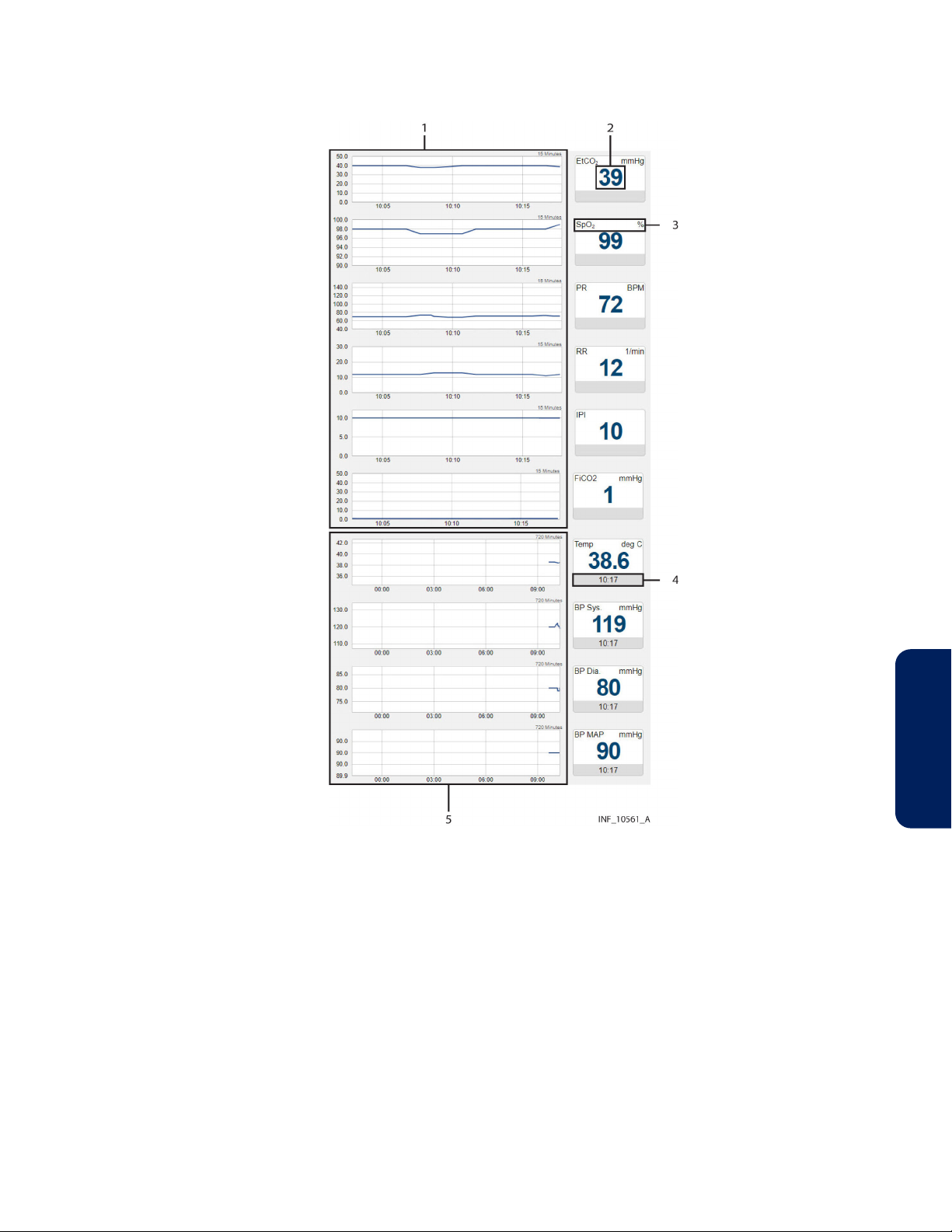
Figure 27. Parameter Panel (multiparameter monitor data)
1. Trend panel with trend tiles
(continuous data)
2. Parameter value
3. Parameter name and unit of measure
Note: The parameter panel layout shown is for the Welch Allyn™* Connex™* 6700 and
Welch Allyn™* Connex™* 6800 vital signs monitors. Other multiparameter monitors that
report different parameters will have a different panel layout.
Note: An episodic timestamp indicates the collection time for the parameter in question,
using a 24-hour clock.
Note: Episodic parameter tiles will show a missing data indicator (“––”) if the platform has
not received data for the parameter for 24 hours.
Note: For more information on trend tiles, see Trend Panel, page 46.
4. Timestamp for episodic parameter
5. Trend panel with trend tiles (episodic
data)
Reference Manual English 43
4

Figure 28. Parameter Panel (four-channel regional saturation monitor data)
1. Sensor channel
2. Parameter value
3. Parameter name and unit of measure
4. Parameter upper and lower alarm
limits (if set)
Figure 29. Parameter Panel (two-channel regional saturation monitor data)
1. Parameter value
2. Sensor channel
3. Parameter upper and lower alarm
limits (if set)
4. Parameter name and unit of measure
Note: Not all devices monitor all parameters the platform can show for that device type. If
the device does not monitor a particular parameter, the tile for that parameter will not
appear in the parameter panel.
Note: The screen captures for the Device Detail screen show examples of data for specific
device types. Data appearing on the Device Detail screen will vary by device type, and also
among devices of the same type, depending on operation mode and settings, parameters
supported, and the communication protocol used. Not all data shown in the screen
captures may be shown for all devices.
Parameters shown are specific to the device and ventilation mode or sensor type selected.
Reference the operator’s manual for the device for more information.
If data is unavailable for a parameter the device normally monitors, two dashes (--) will
appear in the tile.
44 Reference Manual English

Regardless of device type, if any parameters are outside alarm limits set on the device, an
alarm icon will appear below the lower right corner of the tile, and the tile will change color
to red (indicating a high-priority alarm) or yellow (indicating a low-priority or mediumpriority alarm). If audible alerts are enabled, an alert tone will also sound. See Audible
Indicators, page 192.
Note: If an audible alert sounds, the alert will be related to the alarm message with the
highest priority on the linked device with the highest priority. This device may not be the
device that is currently selected.
If a reset alarm occurs for a parameter, the reset alarm icon will appear below the lower
right corner of the tile, and the tile will change color to blue. See Visual Indicators,
page 203.
To access detailed trend data for individual parameters, click on any tile. See View
Parameter Trend Data, page 48.
4.5.2.4. Waveform Panel
The waveform panel shows real-time waveform data for the selected device.
Figure 30. Waveform Panel (ventilator data)
For ventilators, loop waveforms (showing the most recent monitored breath) and scalar
waveforms (showing a collection of breaths over time) appear here.
Figure 31. Waveform Panel (pulse oximeter data)
Figure 32. Waveform Panel (capnography monitor data)
For pulse oximeters and capnography monitors, waveform data for the most recent ten
seconds monitored appears here.
Waveforms shown vary by device and configuration; reference the operator’s manual for
the specific device for more information.
4
Reference Manual English 45

If a particular waveform is not supported, or data is unavailable for a supported waveform,
the message “No Data Available” will appear in the panel for that waveform.
To access more detailed information for a specific waveform, click on the waveform.
See View Waveform Detail, page 49.
4.5.2.5. Settings Panel
The settings panel shows the settings for the currently selected device, with indicators for
unused and changed settings.
Figure 33. Settings Panel (ventilator settings)
1. Device mode label (mode changed)
2. Settings tile (setting changed)
3. Device mode label (mode unchanged)
4. Settings tile (setting unchanged)
5. Settings tile (setting not used or not
supported)
Note: The Device Detail screen settings panel only shows settings data for ventilators.
The tiles in the settings panel are the same regardless of the device linked; active and
unused tiles are specific to the device and device mode. For details on settings, reference
the operator’s manual for the specific device.
If a setting shown in the settings panel is changed on the device, the tile showing that
setting will change color to show a blue outline, or the label indicating a device mode will
be outlined in blue. Click on the tile to view details of, and acknowledge, changes to
settings. See Device Detail Screen (Settings Panel), page 209.
Note: Changes made on the device to any setting shown in the settings panel will trigger a
setting change notification in the event panel. Changes to any alarm limit setting will also
trigger a setting change notification in the event panel, but are not denoted on the
corresponding tile in the parameter panel.
4.5.2.6. Trend Panel
The trend panel shows trend data for the previous 15 minutes for parameters measured by
the currently selected device.
46 Reference Manual English

Figure 34. Trend Panel
1. Parameter trend line
2. Parameter alarm limit indicator line
3. Parameter trend time axis
Note: The Device Detail screen trend panel only shows trend data for pulse oximeters,
capnography devices, and certain multiparameter monitors.
In addition to the trend line, each trend tile has dotted indicator lines for upper and lower
alarm limits for the associated parameter, as set on the device (and if the device reports
them to the platform). For details on settings, reference the operator’s manual for the
specific device.
Note: Clicking on a parameter trend tile will open the Parameter Trend window for that
parameter.
4.5.2.7. Event Panel
The event panel shows recent device alarms and notifications that require the user to
acknowledge them.
Figure 35. Event Panel
4. Parameter trend value axis
5. Parameter trend time interval
indicator
6. Parameter panel with parameter tiles
4
1. Alarm/notification icon
2. Alarm/notification message
3. Settings icon
To view details of alarms, or to view details of and acknowledge notifications, click on an
alarm or a notification message. See Device Detail Screen (Event Panel), page 197
or page 209.
4. Time elapsed since alarm or
notification onset
5. Setting change indicator
Reference Manual English 47

4.5.3. Select a Device
When initially accessed, the Device Detail screen shows details for the device with the
highest priority, based on device type, whether the device is the primary device, and on
priority of active alarms if any are present.
To select a different device:
1. Find the tab showing the icon for the desired device in the patient header panel.
2. Click on the tab for the desired device. Data for the device will appear in the other
panels on the screen.
See Event Priority, page 201 for device priority details.
4.5.4. Manage Device Connections
Users can access device connection controls from the device header panel to attempt to
reconnect or replace devices that have lost communication with the platform, or to unlink
devices from patients in the platform.
See Device Connection Functions, page 62 for details.
4.5.5. View Parameter Trend Data
To view recent trend data (including alarm conditions and setting changes) for a
parameter, click on the desired parameter tile to open the Parameter Trend window.
Figure 36. Parameter Trend Window
4.5.5.1. Default Data
The default data shown is for the previous 15 minutes. Click on the drop-down box at lower
left for other options (30 minutes, or 1, 2, or 4 hours).
Upper and lower alarm limits set on the device for this parameter are indicated by red
dotted lines. (The vertical axis is scaled automatically according to the limits set for the
parameter.)
4.5.5.2. Additional View Options
Alarms and setting changes occurring during the timeframe shown are indicated on the
trend graph with appropriate icons. To view the alarm message associated with an alarm,
click the desired alarm icon.
48 Reference Manual English

Figure 37. Parameter Trend Window (alarm and setting change icons and alarm message
shown)
To get the exact value for the parameter at any point on the trend data graph, simply click
on the line at the desired time point.
Figure 38. Parameter Trend Window (specific data point shown)
To view a different part of the trend graph not currently shown (if any), click and drag the
graph to either the left or the right.
To refresh the trend graph to show the most recent data, click Refresh.
4
To close the Parameter Trend window, click the X at upper right in the window.
4.5.6. View Waveform Detail
To view a more detailed view of any waveform shown in the waveform panel, click on the
desired waveform to open the Waveform Detail window.
Reference Manual English 49

Figure 39. Waveform Detail Window
4.5.6.1. Default Data
The default data shown is for the previous breath for a ventilator waveform, or for the
previous minute for waveforms from other device types. Click on the drop-down box at
lower left for other options (2, 4, or 8 breaths for a ventilator waveform, or 2, 4, or 8 minutes
for other waveforms).
4.5.6.2. Additional View Options
To get the exact value at any point on the waveform, simply click on the line at the desired
time point.
Figure 40. Waveform Detail Window (specific data shown)
If viewing waveform detail for multiple waveforms at once, specific data will be shown on
all waveforms for the time point selected.
50 Reference Manual English

Figure 41. Waveform Detail Window (specific data shown for multiple ventilator
waveforms)
To refresh the waveform view to show the most recent data, click Refresh.
To close the Waveform Detail window, click the X at upper right in the window.
4.5.7. Manage Patient Detail
Users can view patient information, including the bed location and platform users assigned
to any patient, directly from the patient header in the Device Detail screen. Users (except
for those using the platform on optional dedicated bedside display units) can also edit
identifying information and locations for patients.
To access patient information, click the Patient Detail tab in the patient header.
Figure 42. Device Detail Screen (patient information fields)
4
The following information appears here:
■
Name—The patient’s name (last name first)
■
ID—The patient’s identification number
Reference Manual English 51

■
DOB—The patient’s date of birth (if entered)
■
Location—The patient’s location, including all associated areas starting with the
highest-level area and ending with the patient’s bed (for details on locations in the
platform, see Locations, page 167)
■
Primary Contact—The usernames and assignment types (permanent or shift-based) of
all users who have primary responsibility in the platform for this patient
■
Secondary Contact—The usernames and assignment types (permanent or shift-based)
of all users who have secondary responsibility in the platform for this patient
■
Monitoring Only—The usernames and assignment types (permanent or shift-based) of
all users who are only monitoring this patient in the platform
The Discharge Patient from System button allows the user to discharge this patient in the
platform. See Discharge (Remove) a Patient, page 65 for details.
4.5.7.1. Edit Information for a Patient
To update patient information:
1. With the patient information fields shown, click on the edit button next to the Name,
ID, or DOB field to open the Update Patient Information window.
Figure 43. Update Patient Information Window
2. ID—The ID number currently used for the patient appears here. If desired, edit this
number, then click the magnifying glass icon to make sure the new number is not in
use. (If changing the ID number for the patient, all patient information will need to be
reentered in this window.)
3. First Name—The first name currently used for the patient appears here. If desired, edit
this name. (This field is optional.)
4. Last Name—The last name currently used for the patient appears here. If desired, edit
this name. (This field is optional.)
5. Date of Birth—The date of birth currently indicated for the patient appears here. If
desired, edit this date. (This field is optional.)
6. Click Save to update the information in the platform.
4.5.7.2. Change a Patient Location
To change a patient”s location:
1. Click on the tile for the desired patient to access the Device Detail screen.
52 Reference Manual English

2. Click on the Patient Detail tab to access patient information.
3. Click on the edit button next to the patient’s room number in the upper left corner of
the patient header Location field to open the Update Patient Location window.
Figure 44. Update Patient Location Window
4. Old Location—The patient’s current location in the platform appears here.
5. New Location—Click on the drop-down box to view available locations, then click on a
location in the list to select it.
6. Click Save to update the location in the platform. The patient’s information will appear
in the bed tile for the new location in the Tile View.
Note: When updating a patient’s location, if any device not currently associated with the
new location is currently linked to the patient, a message will appear indicating that the
patient’s new location does not match the location associated with the device. See Manage
Device Inventory, page 109 for details on updating location assignments for devices.
4.5.8. View Event Rules
To access a dialog showing current delay rules in use for alarms and notifications, click on
the settings icon in the upper right corner of the Device Detail screen event panel.
Figure 45. Rules and Settings Dialog (example delay rules shown)
The name and description of the current rule set in effect for the selected device appears at
upper left.
The following information appears in the Alarm Rules panel for each event (an alarm of a
particular priority level, or a specific device alarm) defined in the rule set:
4
■
Description—The device alarm priority level or the specific device alarm
■
System Delay—The delay (if any) before the indicated event will annunciate in the
platform
Reference Manual English 53

■
Primary Contact Delay—The delay (if any) before the indicated event will trigger an
email or SMS message to users assigned to the affected patient as primary contacts
■
Secondary Contact Delay—The delay (if any) before the indicated event will trigger an
email or SMS message to users assigned to the affected patient as secondary contacts
This dialog allows users to view the rule set in effect for the currently selected device, but
does not allow changes. Administrative users set up and maintain rule sets and determine
where they are applied. For more information on setting up delay rules, see Add or Edit a
Rule Set, page 115, and Define Alarm and Notification Rules, page 119.
4.5.9. Manage Settings
The platform does not allow users to directly change settings, except for certain derived
parameter algorithms. Users can change alert threshold settings for such algorithms from
the Device Detail screen, according to the setting rules established for the algorithm.
To access a dialog showing current settings and setting rules, click on the settings icon in
the upper right corner of the Device Detail screen event panel.
Figure 46. Rules and Settings Dialog (example alert thresholds shown)
Note: The alert thresholds shown in Figure 46 are purely illustrative. Individual algorithms
have their own specific settings. Basic functionality described here is the same for all
algorithms.
The following information appears in the Alert Thresholds panel of the dialog for each alert
supported:
■
Name—The name of the alert threshold
■
Value—The value to which the alert threshold is currently set
■
Min—The lowest value to which the threshold can be set
■
Max—The highest value to which the threshold can be set
■
Default—The default value for the alert threshold
To change setting rules:
54 Reference Manual English

1. Click in the Value field for the desired threshold and enter a new value. The value
entered must be no lower than the value shown in the Min field, and must be no
higher than the value in the Max field.
2. When finished, click Save to exit the dialog.
For details on thresholds used with a specific algorithm, consult with Medtronic
Professional Services.
Administrative users set the minimum, maximum, and default thresholds (that is, the Min,
Max, and Default values appearing in the Rules and Settings dialog) in the Vital Sync™
informatics manager. These thresholds apply to all devices of a specific type that use
specific setting rules in the platform. For more information, see Define a Setting Rule,
page 121.
4.6. All Patients and Devices Screen
The All Patients and Devices screen provides users with a summary of all patients and
linked devices, assigned personnel, and current status. This screen is the home screen for
link managers.
To access the All Patients and Devices screen:
1. Hover over the navigation bar’s user function button to access the function menu.
2. Select All Patients and Devices.
Figure 47. All Patients and Devices Screen
4
4.6.1. Availability by User Role
Supervisors and link managers may use all functions in the All Patients and Devices screen.
Clinicians do not have access to this screen, nor is it accessible from a central monitoring
station or optional dedicated bedside display unit.
4.6.2. Patient and Device Information
Information shown for each patient includes:
Reference Manual English 55

■
Location—The room number or location identifier
■
Patient—The patient’s name
■
Monitored By—The first user to whom the patient is assigned
■
Devices—The device or devices linked to the patient
■
Status—The currently active alarm or notification (if any) with the highest priority
Note: Before acting on information shown in the platform, assess the patient at the
bedside.
Note: The platform’s data displays are informational. Except as specified for derived
parameter algorithms with adjustable alarm thresholds, the platform does not provide the
ability to change settings or control linked devices in any way (including adjusting or
silencing device alarms).
Note: The All Patients and Devices screen shows all patients currently monitored in the
platform, not just those patients who are assigned to the supervisor currently logged in.
There may be multiple pages of patients and devices; if the desired patient or device is not
immediately visible, navigate through additional pages to find the patient or device.
4.6.3. Additional View Options
The default view for the All Patients and Devices screen is of all patients currently
monitored in the platform, along with all devices currently linked to patients. Users can also
view currently unassigned patients and devices.
To change the patient and device view:
1. Hover over the drop-down menu near the upper right corner of the screen.
2. To show only devices communicating with the platform but not currently linked to any
patients, select Unassigned Devices. To show only patients not currently assigned to
any users, select Unassigned Patients. To select all patients regardless of status, select
All Patients. A check mark will appear next to the currently selected view option.
If there are no unassigned patients or devices, a message indicating as such will appear
after selecting the view option.
4.6.4. View Patient and Device Detail
Users can access the Device Detail screen from the All Patients and Devices screen.
To access patient and device detail:
1. Navigate the All Patients and Devices screen until the row for the desired patient is
visible.
2. Click anywhere in the row showing the desired patient. The Device Detail screen will
appear.
See Device Detail Screen, page 36 for more information.
4.6.5. View Patient Assignments
The first user to whom a patient is assigned appears in the Monitored By field.
To view all users to whom a patient is assigned:
1. Navigate the All Patients and Devices screen until the row for the desired patient is
visible.
2. Hover over the green triangle in the Monitored By field. The names of all users to
whom the patient is assigned will appear in a tool tip next to the mouse cursor.
56 Reference Manual English

Figure 48. All Patients and Devices Screen (assignments shown for a patient)
4.7. Patient and Device Links
For users to be able to view device data for patients, devices that are communicating with
the platform must be linked to patients in the platform.
The Admit Patient screen provides access to primary device linking functionality, including
creating or searching for patient records and linking devices to patients. Other linking
functions, including choosing primary devices, and managing patient name and location
data, device links, and connections, are accessible from the Device Detail screen.
Users may also link activated derived parameter algorithms, using the same procedures as
those used to link devices.
Note: The terms “device category” (as used in the software user interface and in this
section) and “device type” (as used elsewhere in this manual) are interchangeable.
4.7.1. Availability by User Role
Clinicians, supervisors, link managers, and central monitoring station users may use all
functions in the Admit Patient screen. Bedside unit users do not have access to the Admit
Patient screen.
Clinicians, supervisors, link managers, and central monitoring station users may use all
other device linking and device connection functions. Bedside unit users cannot use these
functions, since their access to device detail is view-only.
4.7.2. Link a Patient and a Device
Users create new patient records in the platform and link devices to those patients via the
Admit Patient screen.
Once a patient record is created, the Device Detail screen offers the ability to link additional
devices to a patient who already has devices linked in the platform.
4.7.2.1. Access
To access the Admit Patient screen from any screen:
4
1. Hover over the navigation bar’s user function button to access the function menu.
2. Select Admit Patient.
To access the Admit Patient screen from the Tile View, do any of the following:
Reference Manual English 57

■
Drag and drop a tile for the desired unassociated device (if it is visible in the Tile View)
onto the desired bed tile. A dotted line will appear around the edge of the bed tile.
Figure 49. Tile View (device tile dragged onto bed tile at lower left)
■
Click on a tile for an unassociated device not currently linked to any patient.
■
Click on an empty bed tile.
■
Click on a tile for an unassociated device.
Figure 50. Admit Patient Screen
Information appearing in the Admit Patient screen varies depending on how the user
accesses it. If accessed from the common navigation bar, all fields will be empty. If accessed
from the Tile View, information for the location or device selected (depending on the tile
clicked) will appear.
■
If accessed from the user function menu, all fields will be empty.
■
If accessed by dragging and dropping a device tile onto a bed tile in the Tile View,
location and device information will appear. If a patient is already assigned to the bed,
that patient’s information will also appear.
■
If accessed by clicking a bed tile in the Tile View, location information will appear; other
fields will be empty.
58 Reference Manual English

■
If accessed by clicking a device tile in the Tile View, device information will appear;
other fields will be empty.
4.7.2.2. Field Entry
Users can link patients to any available device within the platform. A device is considered
available if it is currently in the device inventory, connected to and communicating with
the platform, and not linked to any other patient. If the patient ID number entered is not
currently in the platform database, linking the device also creates a record for that patient.
Note: Instructions for all field entries in this screen are presented in this section. However,
not all fields may require entries, depending on how the user accesses the screen.
To select a patient or create a new patient:
1. ID—Enter the desired patient ID, then click the search button to the right of this field.
(If the patient ID for the desired patient is already selected, skip this step.)
If a record for a patient with this ID number is already present, current information for
that patient will appear, including linked devices.
If this is a new patient, a message will appear indicating the ID number was not found.
Completing the linking procedure will create a record in the software for the new
patient.
2. First Name—Enter the patient’s first name, or (if needed) edit the existing name. This
field is optional.
3. Last Name—Enter the patient’s last name, or (if needed) edit the existing name. This
field is optional.
4. Date of Birth—Enter the patient’s date of birth, or (if needed) edit the existing date,
following the date format shown in the lower left corner of the screen. This field is
optional.
5. Location—Select the desired location from available locations in the drop-down list. (If
the desired location is already selected, skip this step.)
After selecting or creating the patient, link any available device or algorithm.
To link a device to the selected patient:
1. Category—Select the device category to link with the patient from the list of available
categories. (If a device is already selected, the category will automatically appear here;
if the category is correct, skip this step.)
2. ID—Select the serial number or network address of the desired device from the dropdown list. (If a device is already selected, its information will automatically appear; if
the device information matches the desired device, skip this step.)
4
Reference Manual English 59

Figure 51. Admit Patient Screen (available device list)
3. Once all fields in the screen have entries, the Link button will be available. Confirm that
the information is correct, then click Link to link the device to the patient. The Device
Detail screen will appear, showing data for the device just linked, as well as a system
message describing the operations just completed.
Note: After linking the device to the patient in the platform, visually check the device itself
to confirm that the data it is showing also appears on the Device Detail screen for that
patient.
Note: If, after linking a device to a patient, both the patient and the linked device are
moved to a different bed, make sure the device inventory is updated to indicate the new
bed association. (Refer to Manage Device Inventory, page 109.) Otherwise, an error
message will appear in the Device Detail screen indicating that the device is not in its
associated location.
Note: Linking a patient and a device adds the new patient record (if new patient data is
entered), and automatically assigns the patient to the current user. If needed, use the
Patient Assignment screen to remove the assignment. See Patient Assignments, page 67.
To link an algorithm to the selected patient:
1. Category—Select Algorithm from the list.
2. ID—Select the desired algorithm from the drop-down list.
3. Once all fields in the screen have entries, the Link button will be available. Confirm that
the information is correct, then click Link to link the algorithm to the patient. The
Device Detail screen will appear, showing data for the algorithm just linked, as well as a
system message describing the operations just completed.
Note: Algorithms must be activated in the software to be available for selection.
See Activate or Deactivate an Algorithm, page 129.
4.7.3. Link Additional Devices
Users can link more devices using the same procedure used for the first device. (See Link a
Patient and a Device, page 57.)
Users also can link more devices to a patient directly from the Device Detail screen for that
patient.
To link another device to a patient from the Device Detail screen:
1. Click on the tile for the desired patient in the Tile View.
60 Reference Manual English

2. In the Device Detail screen, click on the blue Add Device icon in the patient header,
near the top right corner of the screen. A dialog for selecting a device will appear.
Figure 52. Link New Device dialog
3. Category—Select the desired device category from the list of available device types.
4. ID—Select the serial number or network address of the desired device from the dropdown list.
5. Click Link to link the device to the patient. The Device Detail screen will appear,
showing data for the device just linked, as well as a system message describing the
operation just completed.
4.7.4. Manage Primary Devices
Users may designate a linked device as the primary device of that type for the patient.
The platform will show data from the primary device in places where data for only a single
device can be shown (for example, on a bed tile in the Tile View), unless the presence of
active alarms or notifications of higher priority on another linked device overrides this.
Also, alarms and notifications on the primary device have a higher priority in the platform
than alarms and notifications of the same priority on other linked devices. See Event
Priority, page 201.
Note: Designating a primary device is only possible when multiple devices of a particular
type are linked to the patient. If only one device of a particular type is linked to the patient,
it is automatically the primary device, and will remain the primary device if another device
of the same type is subsequently linked to the same patient (unless changed).
To make a linked device the primary device of its type:
1. In the Tile View, click on the bed tile for the desired patient to access the Device Detail
screen.
2. Show the device that is to be the primary device of its type by clicking on its tab in the
patient header.
3. Hover over the device button in the device header to access a drop-down menu.
4
Reference Manual English 61

Figure 53. Device Detail Screen (making a device primary)
4. In the drop-down menu, select Make This Device Primary. The device currently shown
will now be designated as the primary device.
4.7.5. Device Connection Functions
Devices may occasionally lose communication with the software. The software allows
devices to automatically reconnect once able to communicate again. However, if the
affected device has not automatically reconnected, or has been out of communication for a
longer period than the automatic reconnection period set in the software, users may try to
manually reestablish communication with (relink) the affected device. They may also unlink
a device entirely.
To relink a disconnected device or unlink a currently linked device, use the drop-down
menu on the device button in the Device Detail screen.
Note: The frequency with which devices lose communication will vary depending on the
amount of data being passed over the facility’s network, the specific configuration of the
network, and on network settings. Always check the actual device first, especially if
difficulties with maintaining communication are common or remain persistent. If there are
no problems with the device, consult with facility IT personnel or contact Medtronic
(see Obtaining Technical Assistance, page 12).
4.7.5.1. Relink a Device
If a device has lost communication, the bed tile and the device tab in the device header will
show a device disconnection icon.
If the device is selected in the Device Detail screen, the device panels will be blank,
replaced by the device disconnection icon. The date and time when communication was
lost is also shown.
62 Reference Manual English

Figure 54. Device Detail Screen (device disconnected from the platform)
Both the bed tile and the Device Detail screen will also show a message with more detail on
the type of problem, as follows:
■
Device Off—Both the platform and the device are able to communicate with the
network, but no device data is being received.
■
Device Disconnected from Vital Sync—The platform is able to communicate with the
network, but the device is not visible on the network.
■
Device Disconnected - Available to Reconnect—Both the platform and the device are
able to communicate with the network, and the device is available for relinking to the
patient.
To attempt to relink a disconnected device in the Device Detail screen:
1. With the disconnected device selected, hover over the device button in the device
header to access connection functions.
2. Select Reconnect Device.
To attempt to relink a disconnected device in the Tile View:
1. Find the device tile for the disconnected device, ensuring that the serial number or
identifier on the device tile matches the serial number or identifier of the disconnected
device.
2. Find the bed tile for the patient with the disconnected device. (If there are no alarms
active for devices linked to this patient, the message “Device Disconnected – Available
to Reconnect” will appear on the bed tile.)
4
3. Drag the device tile for the disconnected device onto the bed tile.
If communication is reestablished, data for the device will appear, along with a system
message (in blue) indicating success. If communication cannot be reestablished, a system
message (in red) will appear indicating failure.
Note: If the device has been disconnected for longer than the automatic reconnection
interval set in the software, it is possible to link the device to the patient multiple times, or
Reference Manual English 63

for the device to have already been linked to a different patient. To avoid these
possibilities, unlink the device first.
Note: Always check the actual device for problems if reconnecting is unsuccessful.
Note: After linking the device to the patient in the platform, visually check the device itself
to confirm that the data it is showing also appears on the Device Detail screen for this
patient.
4.7.5.2. Unlink a Device
When removing a device from a patient, the device also needs to be unlinked from the
patient in the platform.
To unlink a currently linked device:
1. With the desired device selected, hover over the device button in the device header to
access connection functions.
2. Select Unlink Device. A warning dialog will appear indicating that unlinking is a
permanent action; click Yes to continue with unlinking, or click No to abort and return
to the Admit Patient screen.
Once unlinked, a system message appears confirming that the device is no longer linked to
this patient, and data for the device will no longer appear on the Device Detail screen. Once
the device is available for linking, a tile representing the device will appear in the Tile View.
(For information on how the platform handles data collected on the device after unlinking,
see Device Data Handling After Unlinking, page 177.)
Note: Unlinking a device from a patient only removes the link between the device and the
patient within the platform, stopping the platform from reporting data from that device.
Unlinking does not affect or control the functioning of the actual device in any way.
4.8. Manual Parameter Entry
If a derived parameter algorithm is activated and linked to a patient in the platform, users
may need to enter data manually in order to properly use the algorithm. For information on
setting up and activating algorithms in the platform, see Manage Algorithms, page 127.
Clinicians, supervisors, link managers, and central monitoring stations may enter parameter
data. Bedside unit users cannot enter parameter data, since their access to device detail is
view-only.
To enter parameter data manually:
1. Click on the tile for the desired patient to access the Device Detail screen.
2. If needed, click on the tab for the algorithm in the patient header to show algorithm
information.
3. Click Enter Manual Parameters. A dialog will appear for entry of parameter data.
(Available fields in the dialog may or may not correspond directly to the parameters
shown on the Device Detail screen, depending on the algorithm.)
Note: Data and available manually-entered parameters are specific to the particular
algorithm.
4. Make appropriate entries in parameter fields. When finished, click Save.
64 Reference Manual English

Once parameters are entered, if an alarm state is indicated for the patient according to the
rules defined in the algorithm, an alarm will annunciate in the platform according to rules
and delay setting set up for the algorithm.
Note: Not all algorithms are designed to indicate an alarm state if particular conditions or
combinations of measured or manually entered parameters exist. Some algorithms will
only generate notifications in the platform.
If data for one or more parameters on which the algorithm is dependent is unavailable (for
example, due to disconnection of an associated device, or because the user has not
entered manual parameter data), a notification will appear indicating there is missing data,
along with a time interval since the platform received the most recent usable data.
If the algorithm is prevented from functioning at all, it will appear in the platform (after a
certain period of time) as a disconnected device.
Note: If an algorithm is not functioning, the period of time before it appears in the platform
user interface as a disconnected device is dependent on the frequency with which the
platform reports algorithm data, and on the parameters involved. Generally, the more
frequently the platform reports algorithm data, the shorter the default period is before the
algorithm appears as a disconnected device.
Note: Algorithm disconnection is typically an uncommon occurrence. It may be possible to
reconnect an algorithm, depending on how it is defined. Otherwise, assistance from facility
IT personnel or Medtronic Professional Services may be required.
Note: Algorithm parameters shown on the Device Detail screen or available for manual
entry are specific to each algorithm. Discussion of specific parameters, or the nature and
frequency of manual parameter entry, is beyond the scope of this manual. Consult with
Medtronic Professional Services for details on setting up parameters and algorithms in the
platform.
4.9. Discharge (Remove) a Patient
A patient who is no longer present in a bed must be discharged (removed from
monitoring) in the platform in order to make that bed available in the platform for other
patients.
Clinicians, supervisors, link managers, and users at central monitoring stations may remove
patients. Bedside unit users cannot remove patients, since their access to patient detail is
view only.
Note: Performing the discharge function only removes the patient from monitoring in the
platform. This function is separate from any procedure or system used to physically
discharge the patient from the facility.
Note: The platform can be set up to automatically remove patients with no associated
devices after a specified period of time. Consult with Medtronic Professional Services for
more information.
4
To remove a patient from a bed with currently associated devices:
1. In the Tile View, find the tile showing the patient to be removed.
2. Click on the tile to access the Device Detail screen.
3. Click on the Patient Detail tab on the right side of the patient header to access the
patient information fields.
Reference Manual English 65

4. Click Discharge Patient from System. A warning dialog will appear indicating that this
action will permanently remove the patient from the system.
5. Click Yes to confirm and return to the Tile View. The bed tile for the patient removed
will now only show the location ID and information for the bed’s associated devices.
(Click No or click the X at upper right in the dialog to return to the patient information
fields without removing the patient.)
To remove a patient from a bed with no currently associated devices:
1. In the Tile View, find the tile showing the patient to be discharged. (The tile will be grey
and will show no device data or messages.)
2. Click on the tile to access the Device Detail screen. A message will appear indicating
that the patient currently has no linked devices, and the patient information fields will
also appear.
Figure 55. Device Detail Screen (patient information and Discharge Patient button)
3. Click Discharge Patient from System. A warning dialog will appear indicating that this
action will remove the patient from the system.
4. Click Yes to confirm the discharge and return to the Tile View; the bed tile for the
patient removed will now be completely blank except for the location ID. (Click No or
click the X at upper right in the dialog to return to the patient information fields
without discharging the patient.)
Note: A patient who has no linked devices remains visible and accessible in the platform (in
the most recent associated bed), in case devices need to be linked again later, or all existing
device links need to be replaced.
Note: If the platform is set up to automatically remove patients with no associated devices
from monitoring in the platform, any such patient will remain visible and accessible in the
platform until the time period for automatic discharge has passed.
Note: The discharge function does not clear existing platform data pertaining to the patient
removed.
66 Reference Manual English

4.10. Patient Assignments
The Patient Assignment screen shows patients assigned to the current user, as well as all
patients currently linked to devices in the platform.
Clinicians can manage their patient assignments in this screen, while supervisors can
manage their own patient assignments and those of other users.
Patients selected will appear in the Tile View for the users to whom they are assigned.
Assignments can be permanent, or can be based on work shifts. Patients permanently
assigned to a user will appear in the platform at all times for that user, while patients
assigned to a user for a particular shift will appear during the hours of that shift.
Note: All patients in areas assigned to a user will automatically appear in the Tile View for
that user, unless changed in the Patient Assignment screen. (See Area Assignments,
page 73.)
To access the Patient Assignment screen:
1. Hover over the navigation bar’s user function button to access the function menu.
2. Select Patient Assignment.
Figure 56. Patient Assignment Screen
4.10.1. Availability by User Role
Clinicians, supervisors, link managers, and central monitoring station users can use all
functions in the Patient Assignment screen, as described in this section. Bedside unit users
do not have access to this screen.
4.10.2. Screen Layout
The Patient Assignment screen is divided into two panels, showing current assignments
and patients available for assignment.
Reference Manual English 67
4
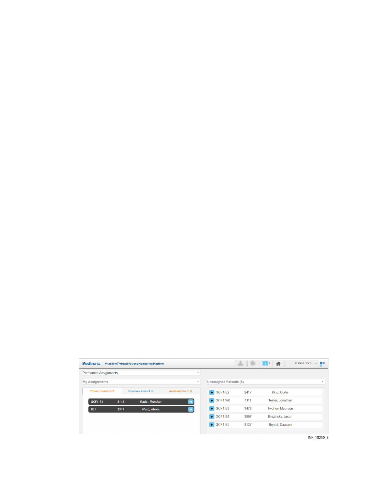
The panel on the left (also called the left-side panel) contains tabs for different types of
patient assignments for a user. These include:
■
Primary Contact tab—If there is an alarm or notification for any patient on this tab, this
user is the primary person to be contacted via Short Message Service (SMS) message or
email
■
Secondary Contact tab—If there is an alarm or notification for any patient on this tab,
this user is a secondary person to be contacted via SMS message or email
■
Monitoring Only tab—If there is an alarm or notification for any patient on this tab, this
user will not be contacted via SMS message or email (the user is only assigned to
monitor the patient, not provide care)
Each tab shows a number denoting the number of patient assignments of that type for this
user.
Tiles representing the patients assigned to the current user will appear on the tab on the
left appropriate to the assignment type. The number of patients assigned to the current
user appears in parentheses above the panel. (For supervisors, the number is in a dropdown menu.)
The panel on the right (also called the right-side panel) contains tiles showing either all
patients currently linked to devices in the platform or all patients currently unassigned to
any user. In either case, the number of patients in this column appears in parentheses in a
drop-down menu above the panel.
If there are too many patients in a panel or a tab to be shown all at once, scroll bars will
appear in that panel or tab.
Each patient tile shows the patient’s room number, ID number and name.
Note: When initially accessed, the Patient Assignment screen shows the current user’s
permanent primary contact patient assignments in the left-side panel (on the Primary
Contact tab), and all patients currently linked to devices in the platform in the right-side
panel.
4.10.3. Show Unassigned Patients
To show only patients who are not currently assigned to any users, click on the drop-down
menu at the top of the right-side panel and select Unassigned Patients.
Figure 57. Patient Assignment Screen (unassigned patients shown)
To once again show all patients in the right-side panel, click on the drop-down menu and
select All Patients.
68 Reference Manual English

4.10.4. Show Another User”s Assignments
Supervisors may show their own patients, or patients assigned to a different user.
To show patients assigned to another user:
1. Click on the drop-down menu at the top of the left-side panel.
Figure 58. Patient Assignment Screen (other user selected)
2. Select the desired user from the list.
Figure 59. Patient Assignment Screen (other user’s assignments)
3. Patients to whom the desired user is assigned as a primary contact user will appear in
the left-side panel. To view other patient assignments, click on the Secondary Contact
or Monitoring Only tabs.
To once again show patients assigned to the current user in the left-side panel, click on the
drop-down menu and select My Assignments.
4.10.5. Show Assignments by Work Shift
Patient assignments can be permanent, or can be associated with a specific work shift.
Patients permanently assigned to a user will appear in the Tile View for that user at all
times. Patients assigned to a user during a specific shift will only appear in the Tile View for
that user during that shift.
To show patient assignments for a specific work shift:
1. With the desired user selected, click in the drop-down menu at the top of the Patient
Assignment screen to show a list of work shifts available in the platform.
Reference Manual English 69
4
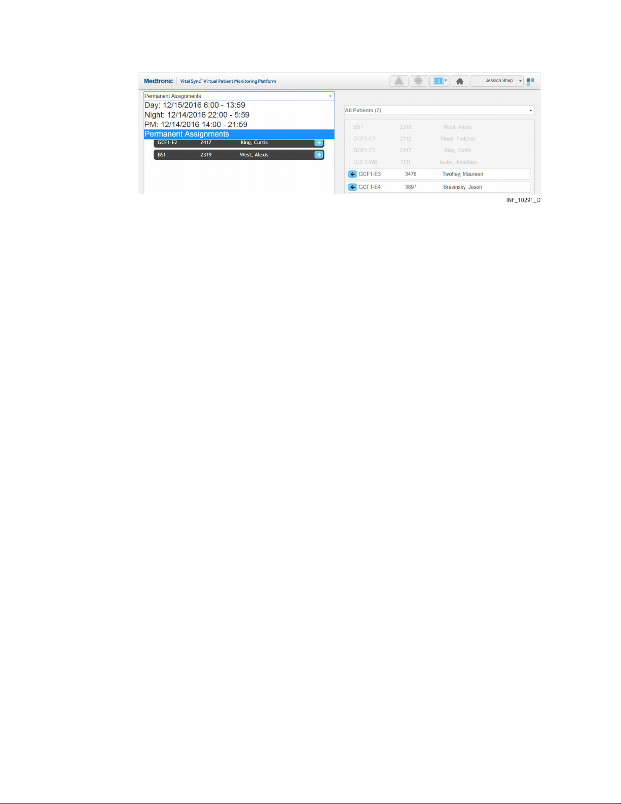
Figure 60. Patient Assignment Screen (shift menu shown)
2. Select the desired shift. The screen will show patients assigned to the currently
selected user. If the patient assignment is associated with the selected shift, it will
appear in color; if not, the patient assignment will appear in grey and will not be
selectable.
For details on work shift setup, see Manage Shifts, page 102.
Note: For added convenience, the date (relative to the current date) when each shift begins
next is shown in the drop-down list.
4.10.6. Change Patient Assignments
Clinicians can assign patients to themselves, change the assignment type for an assigned
patient, or remove their own patient assignments. Supervisors can perform all of these
tasks, and also change assignments for other users.
Assignments are of three types:
■
Primary Contact—This user is the primary person to be contacted (via SMS message or
email) if there is an alarm or notification for this patient
■
Secondary Contact—This user is a secondary person to be contacted (via SMS message
or email) if there is an alarm or notification for this patient
■
Monitoring Only—This user is assigned only to monitor this patient, not to provide
care, and will not receive contact messages even if there is an alarm or notification for
this patient
4.10.6.1. Assign a Patient to a User
To assign a patient as a clinician:
1. Find the desired patient in the right-side panel. If needed, use the scroll bar to move up
or down the list. Any patient available for assignment will appear on a tile in color;
patients already assigned to this user (if any) will appear in grey and will not be
selectable.
2. If the assignment should be permanent (not specific to a work shift), select Permanent
Assignments in the drop-down menu at the top of the screen (if not already selected).
If the assignment is only for a specific work shift, select the desired shift from the dropdown menu at the top of the screen.
3. To assign the patient as a primary contact assignment, click the arrow on the left side
of the tile for the desired patient, or click on the Primary Assignment tab in the left-side
panel and drag and drop the patient tile into the left-side panel. To assign the patient
as a secondary contact or monitoring-only assignment, click on the appropriate tab in
70 Reference Manual English

the left-side panel to open it, then drag and drop the patient tile into the left-side
panel.
To assign a patient as a supervisor:
1. Click on the drop-down menu at the top of the left-side panel.
2. If self-assigning the patient, select My Assigned Patients from the menu. If assigning
the patient to another user, select the name of the desired user from the menu.
Patients assigned to the user selected will appear in the left-side panel; primary
assignments are shown by default.
3. Find the desired patient in the right-side panel. If needed, use the scroll bar to move up
or down the list. Any patient available for assignment will appear on a tile in color;
patients (if any) already assigned to the user currently shown will appear in grey and
will not be selectable.
4. If the assignment should be permanent (not specific to a work shift), select Permanent
Assignments in the drop-down menu at the top of the screen (if not already selected).
If the assignment is only for a specific work shift, select the desired shift from the dropdown menu at the top of the screen.
5. To assign the patient as a primary contact assignment, click the arrow on the left side
of the tile for the desired patient, or click on the Primary Assignment tab in the left-side
panel and drag and drop the patient tile into the left-side panel. To assign the patient
as a secondary contact or monitoring-only assignment, click on the appropriate tab in
the left-side panel to open it, then drag and drop the patient tile into the left-side
panel.
4.10.6.2. Change a Patient Assignment Type
To change a patient assignment type as a clinician:
1. Find the desired patient in the left-side panel. If needed, click on a different assignment
type tab to open it; use the scroll bar to move up or down the list if there are more tiles
than can be shown in the tab.
2. Drag and drop the patient tile into the right-side panel.
3. Click on the tab for the desired assignment type in the left-side panel to open it.
4. Drag and drop the patient tile back into the left-side panel.
To change a patient assignment type as a supervisor:
1. Click on the drop-down menu at the top of the left-side panel.
2. Select either My Assignments (to show patients assigned to the current user) or the
name of the desired user (to show patients assigned to that user).
3. Find the desired patient in the left-side panel. If needed, click on a different assignment
type tab to open it; use the scroll bar to move up or down the list if there are more tiles
than can be shown in the tab.
4. Drag and drop the patient tile into the right-side panel.
5. Click on the tab for the desired assignment type in the left-side panel to open it.
6. Drag and drop the patient tile back into the left-side panel.
4
4.10.6.3. Remove Patient Assignments
To remove a patient assignment as a clinician:
Reference Manual English 71

1. Find the desired patient in the left-side panel. If needed, click on a different assignment
type tab to open it; use the scroll bar to move up or down the list if there are more tiles
than can be shown in the tab.
2. If the patient is assigned only during a specific work shift, select the appropriate shift
from the drop-down menu at the top of the screen. (Tiles for patients assigned during
a specific shift will appear in grey and cannot be selected unless that shift is selected
first.)
3. Click the arrow on the right side of the tile for the desired patient, or drag and drop the
tile into the right-side panel.
To remove a patient assignment as a supervisor:
1. Click on the drop-down menu at the top of the left-side panel.
2. Select either My Assignments (to show patients assigned to the current user) or the
name of the desired user (to show patients assigned to that user).
3. Find the desired patient in the left-side panel. If needed, click a different assignment
type tab to open it, and use the scroll bar to move up or down the list.
4. If the patient is assigned only during a specific work shift, select the appropriate shift
from the drop-down menu at the top of the screen. (Tiles for patients assigned during
a specific shift will appear in grey and cannot be selected unless that shift is selected
first.)
5. Click the arrow on the right side of the tile for the desired patient, or drag and drop the
tile into the right-side panel.
To remove all current patient assignments as a clinician:
1. If removing all permanent assignments, select Permanent Assignments in the dropdown menu at the top of the screen. If removing all assignments for a specific work
shift, select the desired shift from the drop-down menu at the top of the screen. If
removing assignments for a specific shift, the tiles for patients assigned to the shift will
appear in color, while tiles for permanently assigned patients will appear in grey.
2. Click the Remove Assignments button. All tiles appearing in color will disappear from
the left-side panel, and will now appear in color in the “All Patients” view in the rightside panel. The numbers on each tab in the left-side panel will all change to zero,
indicating no patients are assigned.
To remove all current patient assignments for a user as a supervisor:
1. Click on the drop-down menu at the top of the left-side panel.
2. If removing all assignments for the current user, select My Assignments from the list; if
removing all assignments for another user, select the desired user from the list. The
screen will show the patients assigned to the selected user.
3. If removing all permanent assignments, select Permanent Assignments in the dropdown menu at the top of the screen. If removing all assignments for a specific work
shift, select the desired shift from the drop-down menu at the top of the screen. If
removing assignments for a specific shift, the tiles for patients assigned to the shift will
appear in color, while tiles for permanently assigned patients will appear in grey.
4. Click the Remove Assignments button. All tiles appearing in color will disappear from
the left-side panel, and will now appear in color in the “All Patients” view in the rightside panel. The numbers on the tabs in the left-side panel will all change to zero,
indicating no patients are assigned.
72 Reference Manual English

Note: Changes to patient assignments only affect the currently selected user. Patients
shown in either panel of the Patient Assignment screen may also already be assigned to
other users.
4.11. Area Assignments
The Area Assignment screen shows areas in the facility (sometimes also referred to as zones
or areas of care) to which the current user is assigned, as well as areas with no assigned
users or all areas set up in the platform.
Clinicians can manage their own assignments in this screen, while supervisors can manage
their own assignments and those of other users.
All patients in areas selected in this screen will appear in the platform for any user to whom
the area is assigned, unless specifically unassigned from that user. Area assignments can be
permanent, or can be based on work shifts; in the latter case, patients in a particular area
will appear to users to whom the area is assigned during those users’ work shifts.
Note: When an area is assigned to a user, all patients in that area are initially assigned to
that user. To remove specific individual patient assignments after assigning the area, use
the Patient Assignment screen. (See Patient Assignments, page 67.) Also, a user to whom
an area is assigned will not see, in the Tile View, available devices assigned to other areas
without adjusting the view to see all available devices (see Additional Tile View Functions,
page 35 for details).
To access the Area Assignment screen:
1. Hover over the navigation bar’s user function button to access the function menu.
2. Select Area Assignment.
Figure 61. Area Assignment Screen
4
Reference Manual English 73

4.11.1. Availability by User Role
Clinicians, supervisors, link managers, and central monitoring station users can use all
functions in the Area Assignment screen, as described in this section. Bedside unit users do
not have access to this screen.
4.11.2. Screen Layout
The Area Assignment screen is divided into two panels, showing current assignments and
areas available for assignment.
The panel on the left (also called the left-side panel) contains tabs for different types of area
assignments for a user. These include:
■
Primary Contact tab—If there is an alarm or notification for any patient on this tab, this
user is the primary person to be contacted via Short Message Service (SMS) message or
email
■
Secondary Contact tab—If there is an alarm or notification for any patient on this tab,
this user is a secondary person to be contacted via SMS message or email
■
Monitoring Only tab—If there is an alarm or notification for any patient on this tab, this
user will not be contacted via SMS message or email (the user is only assigned to
monitor the area, not provide care to patients)
Note: For an SMS message or email to be sent to a user to whom an area is assigned, the
patient associated with the alarm or notification triggering the SMS message or email also
has to be assigned to that user.
Each tab shows a number denoting the number of area assignments of that type for this
user.
Tiles representing the areas to which the user currently shown is assigned will appear in
one or more of these panes. The number of areas assigned to the user appears in
parentheses above the Primary Contact pane. (For supervisors, the number is in a dropdown menu.)
The panel on the right (also called the right-side panel) contains tiles showing either all
areas set up in the platform or just the areas to which the current user is not assigned. In
either case, the number of areas shown in this column appears in parentheses in a dropdown menu above the panel.
If there are too many areas in a panel (or a pane within a panel) to be shown on a single
screen, scroll bars will appear in that panel or pane.
Each area tile shows the area identifier and description.
Note: When initially accessed, the Area Assignment screen shows the current user’s
permanent primary contact area assignments in the left-side panel (on the Primary Contact
tab), and all areas in the platform in the right-side panel.
4.11.3. Show Unassigned Areas
To show only areas not currently assigned to any users, click on the drop-down menu at
the top of the right-side panel and select Unassigned Areas.
74 Reference Manual English

Figure 62. Area Assignment Screen (unassigned areas shown)
To once again show all areas in the right-side panel, click on the drop-down menu and
select All Areas.
4.11.4. Show Another User”s Assignments
The default listing in the left-side panel is of the areas currently assigned to the current
user. Supervisors may also view areas to which a different user is assigned.
To show the areas to which another user is assigned:
1. Click on the drop-down menu at the top of the left-side panel.
Figure 63. Area Assignment Screen (other user selected)
2. Select the desired user from the list.
Figure 64. Area Assignment Screen (other user’s assignments)
4
To once again show areas assigned to the current user in the left-side panel, click on the
drop-down menu and select My Assignments.
Reference Manual English 75

4.11.5. Show Assignments by Work Shift
Area assignments can be permanent, or can be associated with a specific work shift.
Patients in areas permanently assigned to a user will appear in the Tile View for that user at
all times. Patients in areas assigned to a user during a specific shift will only appear in the
Tile View for that user during that shift.
To show area assignments for a specific work shift:
1. With the desired user selected, click in the field at the top of the Area Assignment
screen to show a list of work shifts defined in the platform.
Figure 65. Area Assignment Screen (shift menu shown)
2. Select the desired shift. The left-side panel will show areas assigned to the currently
selected user. If the area assignment is associated with the currently selected shift, it
will appear on a tile in color; if not, the area assignment will appear in grey and will not
be selectable.
For details on work shift setup, see Manage Shifts, page 102.
Note: For added convenience, the date (relative to the current date) when each shift begins
next is shown in the drop-down list.
4.11.6. Change Area Assignments
Clinicians can assign areas to themselves and remove their own area assignments.
Supervisors can perform both these tasks for themselves and for other users, and can also
change assignment types.
Assignments are of three types:
■
Primary Contact—This user is the primary person to be contacted (via SMS message or
email) if there is an alarm or notification for a patient in this area and assigned to this
user
■
Secondary Contact—This user is a secondary person to be contacted (via SMS message
or email) if there is an alarm or notification for a patient in this area and assigned to this
user
■
Monitoring Only—This user only monitors patients, and will not receive contact
messages even if there is an alarm or notification for a patient in this area who is
assigned to this user
4.11.6.1. Assign an Area to a User
To assign an area as a clinician:
76 Reference Manual English

1. Find the desired area in the right-side panel. If needed, use the scroll bar to move up or
down the list.
2. If this assignment should be permanent (not specific to a work shift), select Permanent
Assignments in the drop-down menu at the top of the screen (if not already selected).
If this assignment is only for a specific work shift, select the desired shift from the dropdown menu at the top of the screen.
3. To assign the area as a primary contact assignment, click the arrow on the left side of
the tile for the desired area, or click the Primary Assignment tab in the left-side panel
and drag and drop the area tile into the left-side panel. To assign the area as a
secondary contact or monitoring-only assignment, click on the appropriate tab in the
left-side panel to open it, then drag and drop the area tile into the left-side panel.
To assign an area as a supervisor:
1. Click on the drop-down menu at the top of the left-side panel.
2. If self-assigning the area, select My Assignments. If assigning the area to another user,
select the name of the desired user from the menu. Areas assigned to the user selected
will appear in the left-side panel; primary assignments are shown by default.
3. Find the desired area in the right-side panel. If needed, use the scroll bar to move up or
down the list. Any area available for assignment will appear on a tile in color; areas
already assigned to the user currently shown (if any) will appear in grey and will not be
selectable.
4. If the assignment should be permanent (not specific to a work shift), select Permanent
Assignments in the drop-down menu at the top of the screen (if not already selected).
If this assignment is only for a specific work shift, select the desired shift from the dropdown menu at the top of the screen.
5. To assign the area as a primary contact assignment, click the arrow on the left side of
the tile for the desired area, or click on the Primary Assignment tab in the left-side
panel and drag and drop the area tile into the left-side panel. To assign the area as a
secondary contact or monitoring-only assignment, click on the appropriate tab in the
left-side panel to open it, then drag and drop the area tile into the left-side panel.
4.11.6.2. Change an Area Assignment Type
To change an area assignment type as a clinician:
1. Find the desired area in the left-side panel. If needed, click on a different assignment
type tab to open it; use the scroll bar to move up or down the list if there are more tiles
than can be shown in the tab.
2. Drag and drop the area tile into the right-side panel.
3. Click on the tab for the desired assignment type in the left-side panel to open it.
4. Drag and drop the area tile back into the left-side panel.
To change an area assignment type as a supervisor:
4
1. Click on the drop-down menu at the top of the left-side panel.
2. Select either My Assignments (to show areas assigned to the current user) or the name
of the desired user (to show areas assigned to that user).
3. Find the desired area in the left-side panel. If needed, click on a different assignment
type tab to open it; use the scroll bar to move up or down the list if there are more tiles
than can be shown in the tab.
Reference Manual English 77

4. Drag and drop the area tile into the right-side panel.
5. Click on the tab for the desired assignment type in the left-side panel to open it.
6. Drag and drop the area tile back into the left-side panel.
4.11.6.3. Remove Area Assignments
To remove an area assignment as a clinician:
1. Find the desired area in the left-side panel. If needed, click on a different assignment
type tab to open it; use the scroll bar to move up or down the list if there are more tiles
than can be shown in the tab.
2. If the area is assigned only during a specific work shift, select the appropriate shift from
the drop-down menu at the top of the screen. (Tiles for areas assigned during a specific
shift will appear in grey and cannot be selected unless that shift is selected first.)
3. Click the arrow on the right side of the tile for the desired patient, or drag and drop the
tile into the right-side panel.
To remove an area assignment as a supervisor:
1. Click on the drop-down menu at the top of the left-side panel.
2. Select either My Assignments (to show the areas assigned to the current user) or the
name of the desired user (to show areas assigned to that user).
3. Find the desired area in the left-side panel. If needed, use the scroll bar to move up or
down the list.
4. If the area is assigned only during a specific work shift, select the appropriate shift from
the drop-down menu at the top of the screen. (Tiles for areas assigned during a specific
shift will appear in grey and cannot be selected unless that shift is selected first.)
5. Click the arrow on the right side of the tile for the desired area, or drag and drop the
tile into the right-side panel.
To remove all current area assignments as a clinician:
1. If removing all permanent assignments, select Permanent Assignments in the dropdown menu at the top of the screen. If removing all assignments for a specific work
shift, select the desired shift from the drop-down menu at the top of the screen. If
removing assignments for a specific shift, the tiles for areas assigned during this shift
will appear in color, while tiles for permanently assigned areas will appear in grey.
2. Click the Remove Assignments button. All tiles appearing in color will disappear from
the left-side panel, and will now appear in color in the “All Areas” view in the right-side
panel. The numbers on the tabs in the left-side panel will all change to zero, indicating
no areas are assigned.
To remove all current area assignments for a user as a supervisor:
1. Click on the drop-down menu at the top of the left-side panel.
2. If removing all assignments for the current user, select My Assignments from the list; if
removing all assignments for another user, select the desired user from the list. The
screen will show the areas assigned to the selected user.
3. If removing all permanent assignments, select Permanent Assignments in the dropdown menu at the top of the screen. If removing all assignments for a specific work
shift, select the desired shift from the drop-down menu at the top of the screen. If
78 Reference Manual English

removing assignments for a specific shift, the tiles for areas assigned during this shift
will appear in color, while tiles for permanently assigned areas will appear in grey.
4. Click the Remove Assignments button. All tiles appearing in color will disappear from
the left-side panel, and will now appear in color in the “All Areas” view in the right-side
panel. The numbers on the tabs in the left-side panel will all change to zero, indicating
no areas are assigned.
Note: Removing an area assignment will unassign patients in that area from the user,
unless the patient in question has been specifically assigned to the user in the Patient
Assignment screen.
Note: Changes to area assignments only affect the currently selected user’s assignments.
Areas shown in either panel may also already be assigned to other users.
4.12. Select User Mode
In addition to their own functions, supervisors can use the Select User mode to view and
use the platform as if logged in as a specific clinician.
Only supervisors can access this platform mode. It is not available at a central monitoring
station or on optional dedicated bedside display units.
To enter Select User mode:
1. Hover over the navigation bar’s user function button to access the function menu.
2. Choose Select User to show a list of clinician users by username.
Figure 66. Select User Menu
3. Select the desired user from the list.
The Tile View screen will appear, with the selected clinician’s name appearing in brackets
on the user function button on the navigation bar.
4
Reference Manual English 79

Figure 67. Navigation Bar and Function Menu (Select User Mode)
The supervisory user can now view and access all platform screens that the selected
clinician is able to access, as if the supervisory user is that clinician.
Note: Select User mode allows access to clinician screens only. Supervisory functions are
not available in this mode.
To exit Select User mode:
1. Hover over the navigation bar’s user function button to access the function menu.
2. Select Exit to return to the Tile View.
Once logged out of Select User mode, the supervisor’s name will appear on the user
function button, and normal functioning for the supervisor will be restored.
Note: Logging out of Select User mode does not log the user out of the platform; it merely
returns the user to supervisory screens and functions.
4.13. Event List
Supervisors may access a listing of platform events in the Event List screen. This is a current,
real-time listing, but can be locked at any time to allow easier viewing of a particular event
or set of events.
Only supervisors may access the Event List screen. It is not available at a central monitoring
station or on optional dedicated bedside display units.
To access the Event List screen:
1. Hover over the navigation bar’s user function button to access the function menu.
2. Select Event List.
80 Reference Manual English

Figure 68. Event List Screen
4.13.1. Event Information
The Event List screen shows the following information for each event:
■
End Time—The time and date of the event
■
Event Code—The event code number
■
Event Description—A brief description of the event, along with the name of the user
performing the associated action
4.13.2. Specify Events Per Page and Sort Order
The default settings for the Event List screen are 25 events per page, sorted by event end
time.
To change the number of events shown:
1. Click the Number of Events to Display drop-down box.
2. Select the desired number. Options are 25, 50, and 100 events.
To change the sort order:
1. Click on the Event Code column heading to sort the list in ascending order by code.
2. To restore the default sort order, click on the End Event column heading.
4.13.3. Lock the Event Display
The Event List screen normally shows new events in real time as they occur.
To lock the event display, select Locked from the Result Set drop-down box. This will freeze
the screen in its current state; no new events will appear while this setting is imposed.
4
To return the event display to dynamic updating, select Unlocked from the Result Set dropdown box.
Note: The platform continues to log all events while the event display is locked. After
unlocking the display, the next event list update will add all events that have taken place
since the display was locked. This may force older events currently being viewed off the
screen; if needed, navigate pages in the list to see those events.
Reference Manual English 81

Note: The amount of event log data that can be stored depends on the storage space
available for report data. If the amount of event log data exceeds the available storage
space, event logging will fail. Consult with Medtronic Professional Services or with facility IT
personnel for information or assistance.
Note: In the event of an unintentional loss of power to the system or systems on which the
platform is installed, the Event List will be unavailable, but once power is restored, will
show subsequent events after platform restart. The time of power loss will not be captured
in the log.
4.14. Reports
Clinicians and supervisors may view and print “snapshot” reports of key oxygenation and
ventilation data for specific patients. Users at a central monitoring station can also view and
print these reports.
Supervisors and link managers may also view and print reports on alarm and setting
change frequency and response time, as well as basic patient statistics and device and
subscription utilization data.
Other reports may also be available, depending on the platform software release and on
platform-related applications installed.
To access reports as a clinician or supervisor from the Tile View:
1. Click on the tile for the desired patient to access the Device Detail screen.
2. Click on the Patient Reports tab on the far right side of the patient header.
Figure 69. Device Detail Screen (Patient Reports tab)
Note: When accessing reports from the Device Detail screen, the patient header for the
currently selected patient remains visible, and tabs for linked devices and algorithms
remain immediately accessible.
To access the reporting module from any other clinician or supervisor screen:
1. Hover over the navigation bar’s user function button to access the function menu.
2. Select Reports.
For details on running available reports, see Chapter 6.
Note: Reports are not accessible on optional dedicated bedside display units.
4.15. Change Password
If allowed by the facility, individual users can change their own passwords if needed (for
example, to replace the password the software randomly generates after a password reset).
Note: Password change functionality is not available (or required) on optional dedicated
bedside display units, or for any central monitoring station account. If encountering
problems accessing the platform from a dedicated bedside display unit or a central
monitoring station, consult with facility IT personnel or, if needed, with Medtronic
Technical Services (see Obtaining Technical Assistance, page 12).
82 Reference Manual English

To change the current user’s password:
1. Hover over the navigation bar’s user function button to access the function menu.
2. Select Change Password to access the Change Password dialog.
Figure 70. Change Password Dialog
3. Old Password—Enter the current password for the current user.
4. New Password—Enter the desired new password.
5. Confirm Password—Enter the password entered in the New Passwordd field.
6. Click Change Password to save the new password, or click the X at upper right in the
dialog to return to the previous screen without changing the password.
Note: If using the software’s native authentication, a strong password (8 to 32 characters
long, including at least one uppercase and one lowercase letter and one number, with
special characters also permissible) must be used. If using the facility’s local authentication,
and password management is enabled in the software, follow facility rules for password
creation.
4.16. Audible Alerts
If allowed in the platform and by facility policy and safety protocols, users can enable and
disable audible alerts for themselves. All users allowed to use audible alerts can also test
the alert tones that will sound for them for each alarm priority level.
Note: Audible alert functionality and user control of audible alerts are established for each
user in the platform in the Add User or Edit User screen. Audible alerts and user control of
audible alerts may or may not be allowed for all users who monitor patients, depending on
facility policy and patient safety protocols. Refer to Manage Users, page 90 for more
information.
To access audible alert settings:
1. Hover over the navigation bar’s user function button to access the function menu.
2. Select Audible Alerts to access the Audible Alerts dialog. The version of the dialog that
appears varies as follows:
4
a. If control of audible alerts is locked out, the dialog shown in Figure 71 will appear.
Reference Manual English 83

Figure 71. Audible Alerts Dialog (control of alerts locked)
b. If control of audible alerts is unlocked, the dialog shown in Figure 72 will appear.
Figure 72. Audible Alerts Dialog (control of alerts unlocked)
Both dialogs show play buttons for testing alerts. If the user has control of alerts unlocked,
radio buttons for enabling and disabling alerts are also present. The current audible alert
setting (enabled or disabled) is indicated by the radio button that appears as selected
when accessing the dialog.
To test audible alert tones:
1. If the Enable radio button is not currently selected, click on it to enable the play
buttons.
2. Click the play button next to High Priority Alarm. The alert tone associated with highpriority alarms will sound. (The default tone is two beeps.)
3. Repeat step 2 with the other two play buttons to hear the alert tones for mediumpriority and low-priority alarms. (The default tone is a single beep for both types.)
4. When finished, click the X at upper right in the dialog to dismiss the dialog and return
to the previous screen.
Warning: If using audible alerts, ensure the sound volume of the PC or mobile device on
which the software is used is sufficient for alerts to be heard and recognized.
Note: If the audible alert tone does not sound during testing, check the PC or mobile device
to ensure the sound volume is sufficient for sounds to be audible. If problems persist,
consult with facility IT staff or with Medtronic Professional Services.
Note: Some mobile devices do not support the sounding of audible alerts from the
platform due to device limitations. Make sure to test audible alert capability on any mobile
device to be used.
84 Reference Manual English

To change the current audible alert setting (enable alerts if disabled, or disable them if
enabled):
1. Click on the radio button for the setting not currently selected.
2. Click Save Setting to save the new setting. (To exit without saving, click the X at upper
right in the dialog.)
3. Upon saving, a message will appear showing the new setting (enabled or disabled).
Click the X at upper right in the dialog to dismiss the dialog and return to the previous
screen.
Note: Users of optional dedicated bedside display units can only test audible alerts, not
enable or disable them.
Note: Audible alerts only sound to indicate alarms on devices and for certain algorithms
linked to patients. Audible alerts do not sound for notifications.
4.17. Help
If needed, users (except those viewing the platform on optional dedicated bedside display
units) can access the most recent applicable release of this manual from within the
platform, and view it in the same browser used to view the platform.
To access the manual for viewing:
1. Hover over the navigation bar’s user function button to access the function menu.
2. Select Help to open the manual (as a Portable Document Format (PDF) file) in a new
browser tab.
4.18. Version Information
If needed, users can access version information for the current installation of the platform,
as well as any platform-related applications that are also installed.
Version information is available to all users, regardless of how they are accessing the
platform.
To show version information:
1. Hover over the navigation bar’s user function button to access the function menu.
2. Select About to access the Version Information dialog.
Figure 73. Version Information (“About”) Dialog
4
Reference Manual English 85

This dialog shows the software’s version number, build number, build date, Unique Device
Identifier (UDI), and licensed features, as well as release information for any platformrelated applications that are also installed. If problems arise with any of these programs,
provide this information to support personnel to aid in troubleshooting.
Scroll down in the dialog if needed to view information. To dismiss the dialog, click the X at
upper right.
4.19. Platform Logout
Clinicians, supervisors, and link managers accessing the platform on a PC or from a mobile
device can log out of the application at any time.
To log out of the platform:
1. Hover over the navigation bar’s user function button to access the function menu.
2. Select Log Out.
After logout is complete, the login screen will appear.
Note: To maintain password integrity when using a shared computer, when done using the
platform, make sure to log out. Closing the Web browser does not log out the current user.
Note: The logout function is not available on optional dedicated bedside display units or at
central monitoring stations. Users should lock down the unit or station display if it is
unattended.
86 Reference Manual English

5. Administrator Operation
5.1. Overview
This chapter describes functionality and operation of the Vital Sync™ virtual patient
monitoring platform and informatics manager for administrative users.
For clinician, supervisory and link manager functionality, see Chapter 4.
Note: The terms “administrator” and “clinical administrator,” as used here, refer only to
types of users and to roles fulfilled when using the software. These terms do not necessarily
correspond to similar titles used for employees of any particular facility, nor to functions
those employees perform at that facility.
5.2. Navigation and Basic User Interface
This section details navigation and user interface features commonly encountered when
using the software.
Note: Do not use the browser’s “forward” or “back” buttons to navigate in the software.
Only use links and buttons provided in the software’s user interface.
Note: Screen captures in this manual are representative. Actual screens may vary slightly
from those shown here, depending on the specific software build used, how the user is
accessing and viewing the platform, and specific facility requirements. Also, the size and
position of tiles and other screen elements will vary with the number of elements present
and the size of the browser window. Finally, the format in which dates appear may differ by
software localization.
5.2.1. Screen Links
Navigation links appear near the top of all administrative screens.
Figure 74. Example Administrative Navigation Links
1. Name of current screen
2. Screens navigated to reach current
screen (“bread crumbs”)
3. Permanent link to Reference Manual
4. Permanent link to version information
dialog
Click a link to access the indicated screen, window or function.
5.2.2. Multi-Page Lists
Certain screens may list more records than can be shown on a single screen. When this
occurs, links for navigation will appear below the list, as follows:
5. Permanent link to Change Password
dialog
6. Username of administrative user
currently logged in
7. Permanent link to Log Out function
5
■
Numbered links access specific pages in the list. Click a link to navigate to that page.
Reference Manual English 87

■
A link with a ellipsis (...) appears if there are more than five pages in the list. Click this
link to access the next set of numbered links after the set currently shown.
■
Click the < link to show the first page in the list.
■
Click the > link to show the last page in the list.
5.2.3. System Messages
System messages will sometimes appear near the top of the screen (just below the
navigation links) in response to events or user actions.
Figure 75. Example System Message
To dismiss a system message, click the X on the right side of the message box, or navigate
to a different screen.
5.2.4. Save and Cancel Functions
For purposes of creating or updating records in the software, unless otherwise noted,
clicking Save will save the information currently shown on the screen, while clicking Cancel
will exit the screen without changing currently saved information.
5.2.5. Deletion of Field Text
When adding or updating records, click the X to the right of the currently selected field to
clear all text currently in that field. (This only applies to text fields.)
5.2.6. Sort Function
On screens that show lists of items, the heading of any column on which the list can be
sorted will change to italics if the user hovers the cursor over the heading.
Figure 76. Column Sort (cursor and heading to be sorted shown)
To sort the list in ascending alphabetical order in a column, click on the column heading. To
sort the list in descending alphabetical order, click on the heading again.
5.3. Administrative Home Screen
The Administrative home screen provides a dashboard view of the current state of the
software, and provides links to administrative functions.
88 Reference Manual English

This screen automatically appears on administrator or clinical administrator login. To access
it from any other administrative screen, click the Home link near the upper left corner of the
screen.
Figure 77. Administrative Home Screen
5.3.1. Availability by User Role
The Administrative home screen is available to all administrative users. However, only the
System, Alarms, and Parameters and Algorithms dashboard tiles will appear for clinical
administrators.
5.3.2. Dashboard Tiles
The Users dashboard tile shows:
■
The number of users currently set up in the software (including the current
administrative user and any central monitoring station user accounts)
■
The number of users set up in each user role
■
A link to the Manage Users screen (see Manage Users, page 90)
■
A link to the Manage Shifts screen (see Manage Shifts, page 102)
The Bedside Displays tab shows:
■
The number of bedside unit users currently set up in the software
■
A link to the Manage Bedside Display Users screen
The Devices dashboard tile shows:
■
The number of devices currently connected to the platform
5
■
The number of these devices not currently linked to any patient
■
The number of patients who currently can be viewed in the platform
Reference Manual English 89

■
A link to the Manage Device Inventory screen (see Manage Device Inventory, page 109)
■
A link to the Device Status screen (see Device Status, page 111)
The Areas and Beds dashboard tile shows:
■
The number of areas (also known as zones or areas of care) set up in the platform
■
The number of beds set up in the platform
■
A link to the Manage Areas screen (see Manage Areas, page 104)
■
A link to the Manage Beds screen (see Manage Beds, page 107)
The Alarms dashboard tile shows:
■
A link to the Manage Rule Sets screen (see Manage Alarm, Notification, and Setting
Rules, page 114)
■
A link to the Manage Alerts screen (see Manage Alerts, page 123)
The Parameters and Algorithms dashboard tile shows:
■
A link to the Manage Parameters screen (see Manage Parameters, page 126)
■
A link to the Manage Algorithms screen (see Manage Algorithms, page 127)
The System dashboard tile shows a link to system status and utilization reports
(see Reports, page 129).
Note: The administrator role is intended for users who are actively managing day-to-day
software operations, particularly user records, device inventory, application software and
hardware health and performance, and reporting. The clinical administrator role is
intended for users with clinical expertise who are specifically tasked with managing alarm
priorities, alarm and event rules, and derived parameter algorithms, not with active user
and platform support. Software functions described in this chapter work in the same way
for users in either the administrator or clinical administrator role, except if noted otherwise.
5.4. Manage Users
The Manage Users screen allows access to functions for setup of new users and
maintenance of existing users (including editing user information; changing user status;
unlocking, deactivating and deleting user records; and, if enabled, resetting and changing
user passwords).
To access, click Manage Users in the Users tile on the Administrator home screen.
90 Reference Manual English

Figure 78. Manage Users Screen
5.4.1. Availability by User Role
The Manage Users, Create User and Edit User screens are only available to administrators.
Clinical administrators cannot access user management functions, except to change their
own passwords.
5.4.2. User Information
■
Username—The username that this user enters at login
■
Display Name—The name shown for this user when logged in
■
Role—The role assigned to this user in the platform (this determines functions
available to this user when logged in)
Note: The terms “clinician”, “supervisor”, “administrator”, and “clinical administrator”, as
used in this manual, refer only to types of users and to roles those users fulfill when using
the software. These terms do not necessarily correspond to similar titles used for
employees of any particular facility, nor to functions those employees perform at that
facility.
Links for changing user status, resetting passwords, unlocking users, and deleting users
also appear on this screen.
The standard sort order for the user list is alphabetical by username. To reverse the current
sort order, click the Username heading.
5.4.3. User Status
Users are listed in the Manage Users screen according to their current status in the
platform. Active users may log into the platform and use functions appropriate to their role.
Inactive users may not access or use the platform until their user records are reactivated.
(See Change User Status, page 95.)
5
To show inactive users, click the Inactive tab.
Reference Manual English 91

Figure 79. Manage Users Screen (inactive users shown)
To once again show active users, click the Active tab.
5.4.4. Add or Edit a User
Note: If using local authentication, the facility’s information technology department may
assign login credentials; if so, user name and password fields may be unavailable.
Note: User records set up for central monitoring stations appear in the user list, but are not
editable in the Edit User screen. If problems arise with a central monitoring station user
record, contact Medtronic for assistance (see Obtaining Technical Assistance, page 12).
To add a new user record, in the Manage Users screen, click Create User to access the
Create User screen.
92 Reference Manual English

Figure 80. Create User Screen
To access an existing user record for editing:
1. Navigate the Manage Users screen until the desired user record is visible. (If needed,
click the Active or Inactive button to change the user listing.)
2. Click on the username of the desired user to access the Edit User screen.
5
Reference Manual English 93

Figure 81. Edit User Screen
When adding or editing a user, make field entries as follows:
1. Username—Enter the username with which this user will log into the software.
2. Display Name—Enter the name to appear in the user interface for this user.
3. Roles—Click Administrator to give the user access to administrative functions. Click
Clinical Administrator to give the user access to clinical administrative functions. Click
Supervisor to give the user access to clinician and supervisory functions. Click Clinician
to give the user access to clinician functions. (See User Roles, page 17 for user role
descriptions.)
(Administrative functions are described throughout this chapter. For clinician, clinical
administrator, and supervisor functions, see Chapter 4. For more information on
external service functions, consult with Medtronic Professional Services.)
Note: Since the Administrator role allows access to user records in the software,
Medtronic recommends strictly limiting the number of users with this role. However,
always assign the Administrator role to at least two users, to help prevent potential
inaccessibility of administrative functions due to user unavailability or inadvertent
password reset.
4. Audible Alerts—Set both the audible alert tone and the user’s ability to enable or
disable it, as follows:
a. Click Multi-Tone to turn on multi-tone audible alerts for this user.
b. Click Single-Tone to turn on single-toned audible alerts for this user.
c. Click Disable to turn off audible alerts for this user. (If selecting Disable, the user in
question will not have access to the Audible Alerts user function menu option
when using the platform.)
d. If this user should not be allowed to disable or enable alert tones (the default
setting), ensure that the Locked check box is checked; click in the box if needed to
check it.
94 Reference Manual English

e. If this user should be allowed to disable or enable alert tones, ensure that the
Locked check box is unchecked; click in the box if needed to uncheck it.
Note: The Audible Alerts field will be unavailable if the user being added or edited is an
administrator or clinical administrator.
Note: The setting of the Audible Alerts field only affects alerts in the platform, and only
for this specific user. Alert settings or audible alarms on individual devices are not
affected.
Note: Some mobile devices do not support sounding of audible alerts in the platform
due to device limitations. Make sure to test audible alert capability on any mobile
device to be used.
5. New Password—If allowed, enter the login password for this user. If using the
platform’s native authentication, this password must be from 8 to 32 characters long,
including at least one uppercase and one lowercase letter and one number. Special
characters are also permissible. If using local authentication, follow the facility’s rules
for password creation.
6. Confirm New Password—If allowed, enter the password just entered in the New
Password field. (If this entry does not match the New Password field entry, an error
message will appear.)
Note: The New Password and Confirm New Password fields are unavailable when
editing an existing user. For details on changing passwords for existing users,
see Manage Passwords, page 97.
7. Mobile Phone Number—If desired (and enabled in the platform), enter the user’s
mobile phone number to allow the platform to send messages to the user’s mobile
phone. (To test whether the user can receive messages at the number entered, click
the Send Test Message button next to this field.)
8. Email Address—If desired (and enabled in the platform), enter the user’s email address
to allow the platform to send email messages to this address. (To test whether the user
can receive messages at the address entered, click the Send Test Message button next
to this field.)
Note: Use the Mobile Phone Number and Email Address fields to support primary and
secondary contact functionality for patient and area assignments, and in conjunction
with rule sets for event annunciation in the platform. See Patient Assignments,
page 67; Area Assignments, page 73; and Manage Alarm, Notification, and Setting
Rules, page 114.
9. When finished with field entry, click Save to save user data, or click Cancel to exit
without saving. In either case, the Manage Users screen will reappear.
5.4.5. Change User Status
Administrators can deactivate or activate users in the Manage Users screen, and can also
delete user records for users who have never logged in.
To deactivate a currently active user:
5
1. Navigate the Manage Users screen until the desired active user record is visible. (If
needed, click the Active button to show active users).
2. Click the Deactivate link for this user. A confirmation dialog will appear.
Reference Manual English 95

Figure 82. User Deactivation Dialog
3. Click Yes to confirm deactivation, or click Cancel (or click the X at upper right in the
dialog) to return to the Manage Users screen without deactivating the user.
Note: Deactivating a user disables the user’s ability to access and use the platform, but does
not delete the user record from the platform database.
Note: The platform removes all current patient and area assignments for a deactivated user.
If reactivated, that user (or a supervisory user) will need to restore patient and area
assignments. See Change Patient Assignments, page 70 and Change Area Assignments,
page 76.
To activate a currently inactive user:
1. Navigate the Manage Users screen until the desired inactive user record is visible. (If
needed, click the Inactive button to show inactive users).
2. Click the Activate link for this user. A confirmation dialog will appear.
Figure 83. User Activation Dialog
3. Click Yes to confirm activation, or click Cancel (or click the X at upper right in the
dialog) to return to the Manage Users screen without activating the user.
To delete a user record:
1. Navigate the Manage Users screen until the desired user record is visible. (If needed,
click the Active or Inactive button to change the user listing.)
2. Click the Delete link for this user. A confirmation dialog will appear.
96 Reference Manual English
 Loading...