

Page 1
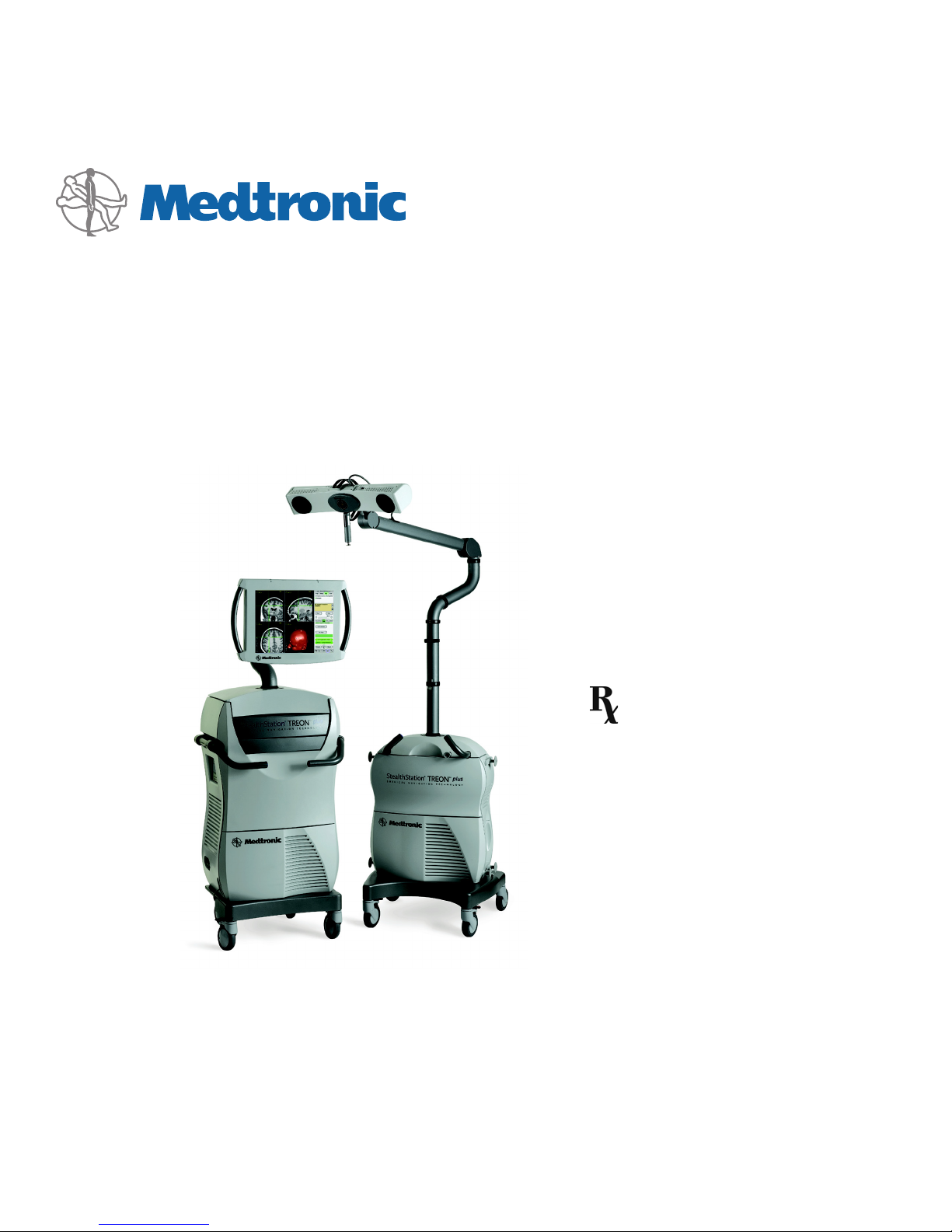
TREON® Treatment Guidance System
System Manual
Part Number 9680169, revision 10
A Guide to Understanding the
TREON
®
Treatment Guidance
System
Read this manual completely prior to
using this device.
c
Page 2

Page 3
Explanation Of Symbols On Package Labeling
The following symbols may appear on system equipment, system packaging, or in this reference guide.
c
The device complies with European Directive MDD 93/42/EEC.
Classified by Underwriters Laboratories Inc. with respect to electric shock, fire, mechanical, and other
specified hazards only in accordance with UL60601-1/CAN/CSA C22.2 NO.601.1.
Control number 87HJ.
Prescription only. Federal law (U.S.A.) restricts this device to sale by or on the order of a physician
.
w
When found in this reference guide, this symbol means: “Warning! Failure to observe could result in
injury or death.” When found on equipment, this symbols means: “Attention: consult accompanying
documentation.”
#
Caution! Failure to observe could result in damaged equipment, forfeited time or effort, or the need to
abort use of the system.
y
Type BF applied equipment, in compliance with IEC60601-1.
Type B applied equipment, in compliance with IEC60601-1.
F
Fragile contents
H
Keep upright
U
Keep dry
Power on. Connect to main power.
Power off. Disconnect from main power.
D
Power on for part of the system (typically energizes the Isolation Transformer and UPS).
Page 4
Power off for part of the system.
Freeze caster
Lock caster angle
f
Use by date specified
k
Single use only. Do not reuse.
_
Quantity
r
Sterilized by ethylene oxide
J
Non-sterile
Protective Earth (Ground)
L
Radio frequency device. Interference may occur in the vicinity of the device.
Do not dispose of this product in the unsorted municipal waste stream. Dispose of this product according
to local regulations. See http://recycling.medtronic.com for instructions on proper disposal of this
product.
China RoHS compliant. Environmental protection use period of 50 years.
Environmental protection use period of 5 years.
Page 5

Tr eo n® Treatment Guidance System Manual v
Table of contents
Table of contents
1. Introduction
Description of the Treon® Treatment Guidance System 1-2
Content of This Manual 1-2
Related Documents 1-3
Conventions 1-3
Intended Use 1-4
Contraindications 1-4
Warnings and Cautions 1-5
Contact Information 1-7
2. System Overview
How the System Works 2-2
Optical System 2-2
System Carts 2-5
Input/Output Panel 2-8
Touchscreen Monitor 2-9
Keyboard and Mouse 2-10
Breakout Box 2-10
Optical Instruments 2-11
System Specifications 2-12
System Classifications 2-13
System Electromagnetic Emissions and Immunity Declarations 2-14
System Set Up 2-20
3. Inside the Cart
Component Locations 3-2
Opening the Viewing Cart 3-5
Opening the Nav Cart 3-6
Docking and Separating the Carts 3-6
Component Connections 3-7
System Computer 3-8
Device Connectivity Diagrams 3-9
Page 6

vi Tr eo n® Treatment Guidance System Manual
Table of contents
Page 7

Tr eo n® Treatment Guidance System Manual 1-1
1
Introduction 1
Description of the Treon® Treatment
Guidance System 1-2
Content of This Manual 1-2
Related Documents 1-3
Conventions 1-3
Intended Use 1-4
Contraindications 1-4
Warnings and Cautions 1-5
Contact Information 1-7
Page 8

1-2 Tr e on® Treatment Guidance System Manual
Introduction
Description of the Treon® Treatment Guidance System
Description of the Treon® Treatment Guidance System
The Treon® Treatment Guidance System is a hardware platform that enables real-time
surgical navigation using radiological patient images. The application software
reformats patient-specific CT or MR images acquired before surgery and displays them
on-screen from a variety of perspectives (axial, sagittal, coronal, oblique). Prior to
operating, the surgeon may then create, store, and simulate progression along one or
more surgical trajectories. As an aid to visualization, the surgeon may also create and
manipulate one or more 3D models of the anatomy. During surgery, the system tracks
the position of specialized surgical instruments in or on the patient anatomy and
continuously updates the instrument position on these images.
If desired, the application software can also show how the actual position and path
during surgery relate to the pre-surgical plan, and can help guide the surgeon along
the planned trajectory. While the surgeon’s judgement remains the ultimate authority,
real-time positional information obtained through the Treon
®
Treatment Guidance
System can serve to validate this judgement as well as guide.
This system manual is intended as a reference document for biomedical engineers or
other qualified personnel who require familiarity with and details about the Treon
®
Treatment Guidance System. This manual is not a software usage manual. For
complete instructions on using a specific software application, refer to the specific
application’s instructions for use (pocket guide).
Content of This Manual
This system manual is intended as a reference document for users who require
familiarity with and details about the Treon
®
Treatment Guidance System. This manual
is not an application usage manual. For complete instructions on using a specific
software application, refer to the specific application pocket guide.
Page 9

Tr eo n® Treatment Guidance System Manual 1-3
Introduction
Related Documents
Related Documents
Consult application-specific pocket guides for software application instructions.
Consult instrument -specific package inserts for instrument instructions. Consult the
Medtronic Navigation Equipment Cleaning and Sterilization sheet (pn 9730713) for
equipment and instrument cleaning and sterilization instructions.
Refer to manufacturer’s guides for information on peripheral devices.
Conventions
This document employs the following conventions:
w
■
Warnings are indicated by the symbol at left. Failure to observe a warning may
result in physical injury to the patient or operator. Pay special attention to these
items.
#
■
Cautions are indicated by the symbol at left. Failure to observe a caution could
result in damaged equipment, forfeited time or effort, or the need to abort use of
the system.
♦
■
Procedures are preceded by diamond symbol at left.
■
References to buttons that appear on the system display are enclosed in square
brackets. For example:
Click the
[Edit...] button.
■
References to menu options that appear on the system display are printed in bold
letters. For example:
Choose
Clear from the list.
■
Instructions to click an object on the screen means to tap the object on the
touchscreen with your finger or some other blunt object. Alternatively, it means to
place the pointer over the object using the system mouse, and depress and release
the left mouse button. Click, Select, and Highlight are used interchangeably.
■
Right-click means click with the right mouse button instead of the left button.
■
Double-click means click twice in rapid succession.
Page 10

1-4 Tr e on® Treatment Guidance System Manual
Introduction
Intended Use
Intended Use
Your Medtronic computer-assisted surgery system and its associated applications are
intended as an aid for precisely locating anatomical structures in either open or
percutaneous procedures. Their use is indicated for any medical condition in which the
use of stereotactic surgery may be appropriate, and where reference to a rigid
anatomical structure, such as the skull, a long bone, or vertebra, can be identified
relative to a CT- or MR-based model, fluoroscopic images, or digitized landmarks of
the anatomy.
Contraindications
Medical conditions which contraindicate the use of a Medtronic computer-assisted
surgery system and its associated applications include any medical conditions which
may contraindicate the medical procedure itself.
Page 11

Tr eo n® Treatment Guidance System Manual 1-5
Introduction
Warnings and Precautions
Warnings and Precautions
w
Warnings :
■
The system and its associated applications should be used only by qualified
medical professionals who are thoroughly trained and experienced in performing
surgery with Medtronic computer-assisted surgery systems.
■
The system and its associated applications should be used only as an adjunct for
surgical guidance. They are not a replacement for the surgeon’s knowledge,
expertise, or judgement.
■
If system navigation seems inaccurate and recommended steps to restore accuracy
are not successful, abort use of the system.
■
Accessory equipment connected to the analog and digital interfaces of the
Medtronic computer-assisted surgery system must be certified according to the
respective IEC standards (e.g. IEC 60601-1 for medical equipment). Furthermore
all configurations shall comply with the system standard IEC 60601-1-1. Any
person who connects additional equipment to the signal input part or signal
output part configu res a medical system, and is therefore responsible for ensuring
that the system complies with the requirements of the system standard
IEC 60601-1-1. If in doubt, contact technical support or your local representative.
■
The system is not suitable for use in the presence of a flammable, anesthetic
mixture with air or oxygen or nitrous oxide. Position the system at least 25cm
from any source of flammable gas.
■
Some system components may contain batteries. Do not recharge or disassemble
batteries. Do not dispose of batteries in fire. Observe local regulations concerning
battery disposal.
■
Discard before use any pre-sterilized component whose sterile packaging appears
to be compromised.
■
There is currently no effective sterilization method for components that are
tainted with the infectious agent that causes Creutzfeld-Jakob Disease (CJD).
Therefore, you must discard immediately after surgery any components that
come into contact with biologic material from patients who carry or are suspected
to carry this infectious agent. As a precaution, drape all non-disposable
components that could otherwise come into contact with such material.
Page 12

1-6 Tr e on® Treatment Guidance System Manual
Introduction
Warnings and Precautions
#
Precautions:
■
Federal law (U.S.A.) restricts this device to sale by or on the order of a physician.
■
The system and its associated applications contain no user-repairable parts. For
repair or replacement of any part of the system or application, contact a technical
support representative.
■
Verify that all relevant instrumentation has been properly cleaned and sterilized
before surgery. Clean and sterilize the components according to the parameters in
the Equipment Cleaning and Sterilization sheet (pn 9730713). Clean nonsterilizable equipment according to the parameters in the Non-Sterilizable
Equipment Cleaning sheet (pn 9733025).
■
The system has been successfully tested against the requirements of
IEC 60601-1-2. However, RF interference could hamper its operation or the
operation of other nearby electrical devices. If you suspect either of these
conditions, move the conflicting equipment farther apart, separate the equipment
with an RF barrier, or discontinue use of the system.
■
Do not exceed the recommended electrical ratings for the system. Exceeding the
ratings could damage the system.
■
The system mouse is not designed for sterilization, and may be damaged if
sterilization is attempted.
■
System components are fragile. Use care when handling system components.
■
Before moving the system cart(s), shut down all components, remove any loose
items from the top of the cart(s), and dock the carts together (if applicable). To
avoid contaminating the inside of the cart(s), clean the power cord(s) before
retracting.
■
Cart storage drawers have a maximum load capacity of ten pounds each.
Page 13

Tr eo n® Treatment Guidance System Manual 1-7
Introduction
Contact Information
Contact Information
Telephone
(800) 595-9709 (technical support)
(720) 890-3200 (general)
(720) 890-3500 (fax)
Regular Mail
Medtronic Navigation, Inc.
826 Coal Creek Circle
Louisville, CO, U.S.A.
80027
Medtronic E.C. Authorized Representative
Medtronic B.V.
Earl Bakkenstraat 10
6422 PJ Heerlen
NETHERLANDS
Tel. 31 45 566 80 00
World Wide Web
www.medtronicnavigation.com
E-mail
E-mail product enhancement requests to: dl.navsuggestions@medtronic.com
Page 14

1-8 Tr e on® Treatment Guidance System Manual
Introduction
Contact Information
Page 15

Tr eo n® Treatment Guidance System Manual 2-1
2
System Overview 2
How the System Works 2-2
System Specifications 2-12
System Classifications 2-13
System Electromagnetic Emissions and
Immunity Declarations 2-14
System Set Up 2-20
Page 16

2-2 Tr e on® Treatment Guidance System Manual
System Overview
How the System Works
How the System Works
The Treon® Treatment Guidance System creates a translation map between all points
in the patient images and the corresponding points on the patient anatomy. After
establishing this map, whenever the operator touches a point on the patient using a
special tracked instrument or pointing device, the computer uses the map to identify
the corresponding point on the images. This identification is called navigation or
localization. A localized point is identified on the system display within multiple
patient image planes and other anatomical renderings.
Optical System
The system determines the position of the instrument and patient in the operating
room by using a camera to track the positions of optical markers affixed to them. In the
case of instruments, the markers are attached directly to the instrument body. In the
case of the patient, the markers are attached to a dynamic reference frame which you
connect to a support mechanism secured to the patient anatomy.
There are two types of optical markers. Some components may have LED optical
markers, and others may have sterile spheres. LEDs (Light Emitting Diodes) generate
and emit infrared light. Sterile spheres reflect infrared light that is emitted by the
camera.
The camera (sometimes called the localizer) detects the optical markers, determines
their spatial positions using the principle of triangulation, and continuously reports
this information to the computer. The computer uses this spatial information, in
conjunction with information regarding the geometry of the instrument currently in
use, to determine exactly where the tip of the instrument is located on the patient
anatomy.
Dynamic Referencing
To maintain accuracy, the system must continuously track the position of the anatomy
during registration and navigation. This is necessary because you may accidentally or
unavoidably move the anatomy or Localizer after patient registration or image
acquisition. If the system did not track the position of the anatomy via the dynamic
reference frame, any movement of the patient or Localizer after registration or image
acquisition would result in inaccurate navigation.
Page 17

Tr eo n® Treatment Guidance System Manual 2-3
System Overview
How the System Works
The device that allows you to register and then track the anatomy is called a patient
reference frame. The reference frame is of a set of optical markers mounted on a metal
frame that can be rigidly positioned with respect to the patient anatomy. Because the
reference frame sits in a rigid, fixed position with respect to the anatomy, any
movement of the anatomy or the camera results in corresponding movement of optical
markers in the camera’s field of view. This enables the camera to detect any movement
of the anatomy and alert the application software, which updates the registration
correlation and thereby maintains accurate navigation.
Without dynamic referencing, any movement of the camera after registration would
invalidate the registration, since the positions of the optical markers would change in
the camera’s field of view. So, dynamic referencing also gives you the flexibility to
reposition the camera at any time.
Each application has its own unique reference frame. Consult the application’s
instructions for use (pocket guide) for more information.
w
Warning: Because the position of the anatomy is defined by the position of the
Reference Frame, it is important to ensure that the frame does not move with respect
to the anatomy from the time of registration until navigation is complete. Slippage or
rotation of the Reference Frame with respect to the anatomy after registration will
result in inaccurate navigation.
Camera
The system camera uses two lenses to geometrically triangulate the spatial coordinates
of each optical marker on the instrument and Reference Frame. In the case of cabled
devices (such as the active registration probe), the camera lenses receive infrared light
signals directly from the LEDs on each device. In the case of passive (wireless) devices,
the passive spheres on each device reflect light emitted by infrared illuminators on the
camera back into the camera lenses. The camera continuously communicates the
location of each LED or passive sphere to the system. In order to effectively “see” the
LEDs or passive spheres, the camera must be aimed toward the devices and positioned
at the proper distance from them.
Page 18

2-4 Tr e on® Treatment Guidance System Manual
System Overview
How the System Works
Figure 2-1. System camera and laser positioning system
♦
To dock the camera and its boom:
1. Rotate the camera boom and arms such that they align with their respective tick
marks (the tick marks indicate the “home position” for the joints.
2. Swivel the post until the arm lock audibly clicks into place.
3. Align the docking tee of the laser handle with the camera docking port and snap
into place.
Laser positioning system
w
Warning: The laser positioning system transmits laser radiation. Use caution when
operating the device, and never allow the laser beam to enter someone’s eye. Laser
radiation, even at low levels, can damage the eyes.
The laser positioning system (located between the camera lenses) helps approximate
the correct camera aim by projecting a low-power laser beam along the center of the
camera’s field of view. The laser is activated by a trigger button in the handle. Depress
the on/off trigger button to activate the laser, and release the button to deactivate the
laser.
Infrared illuminator
Laser source
On/off trigger
button
Camera lens
Docking tee
Page 19

Tr eo n® Treatment Guidance System Manual 2-5
System Overview
How the System Works
System Carts
The Treon® Treatment Guidance System has two separate but complementary carts;
the Viewing Cart and the Nav Cart. The carts may be docked together as a single unit,
or separated for positional flexibility and convenience during surgery. The system carts
are suitable for continuous operation.
The Viewing Cart contains the power supply, computer, and all related peripheral
devices (see Figure 2-2). The Viewing Cart can be used as a stand-alone surgical
planning station.
The Nav Cart acts as the base for the camera and contains the Tool Interface Unit (TIU)
and a storage drawer. The Nav Cart is connected to the Viewing cart via a
communication cable which also supplies the necessary power for the camera and the
TIU. See Figure 2-3.
Page 20

2-6 Tr e on® Treatment Guidance System Manual
System Overview
How the System Works
Figure 2-2. Viewing Cart exterior front and back
1
2
3
4
5
6
7
8
9
10
11
12
1. Articulating Arm
2. Touchscreen
3. Chicane
4. Storage Drawer
5. Keyboard/Mouse Drawer
6. System Side Panel
7. Media Bays
12
8. Cart Docking Mechanism
9. Cart Communication Cable Connection
10. On/Off Switch
11. Power Cord Outlet
12. Caster Locks
13. Cable Wraps
13
13
Page 21

Tr eo n® Treatment Guidance System Manual 2-7
System Overview
How the System Works
Figure 2-3. Nav Cart exterior front and back
4
5
6
7
8
9
11
10
12
13
1
2
3
8. Cart Docking Mechanism
9. Storage Drawer
10. Cable Wraps
11. Cart Communication Cable
12. Breakout Box
13. Caster Locks
1. Camera Boom
2. Camera
3. Laser Pointer
4. Camera Docking Port
5. Chicane
6. Post
7. Post Lock
10
Page 22

2-8 Tr e on® Treatment Guidance System Manual
System Overview
How the System Works
Input/Output Panel
The right side of the cart contains a side panel with external connection ports for
various input and output devices.
Figure 2-4. System I/O panel
Side panel connectors
Printer: Connects the system to a printer.
Network: Connects the system to the site Local Area Network (LAN).
Modem: Connects the system modem to an external telephone line.
Audio In: Connects the system to an audio input device such as a microphone.
Video In: Connects the system video input board to the composite video output of an
external source.
Video Out: Connects the system video output to the composite video input of an
external source.
Page 23

Tr eo n® Treatment Guidance System Manual 2-9
System Overview
How the System Works
S-Video In: Connects system video input to the S-VHS video output of an external
source.
S-Video Out: Connects system video output to the S-VHS video input of an external
source.
Serial Ports 1-3: Connects the system to external serial devices.
AUX 1-4: These ports are accessory ports for system expansion and are normally
empty.
Wireless Network: Feature pending future development. When enabled, will connect
the system to the site wireless network (where applicable). A network jack protruding
from the Wireless Network Port connects to the Network connector. If the wireless
network connection is interrupted, simply remove the Wireless Network jack and plug
the Local Area Network into the Network connector.
Touchscreen Monitor
The touchscreen monitor is a high-resolution, flat panel computer display with builtin speakers. The display is visible at angles up to 80° from perpendicular. When placed
in the surgical field, the touchscreen allows the physician to control the system without
the need for an assistant, keyboard, or mouse. To select an item on the screen, tap the
item with the sterilized stylus. For any software fields that require text entry, a virtual
keyboard will appear on-screen with buttons that can be touched like a typewriter.
♦
To dock the monitor:
1. Adjust (push down) the articulating arm such that the arm button is in the lock
position. There will be an audible click when the arm locks.
2. Adjust the monitor arm such that it is in the lock position. The lower elbow of the
chicane will be at its closest point to the back of the system cart.
3. Rotate the monitor such that the face is pointing down.
4. Push the monitor down toward the back of the cart.
Page 24

2-10 Tr eo n® Treatment Guidance System Manual
System Overview
How the System Works
Keyboard and Mouse
Although the touchscreen eliminates the need for a keyboard and mouse, a keyboard
and mouse are provided in the cart’s lower storage drawer for use in certain
circumstances. The drawer also features a built-in mouse tray.
Breakout Box
The Breakout Box acts as a junction box for various hardware devices, like the
footswitch, reference frame, 3-marker probe, and 4-marker probe. The breakout box
does not contain any user-serviceable parts.
Figure 2-5. Breakout box
The breakout box can hook onto the operating room bed rail or the Nav Cart. During
transportation and storage, attach the breakout box to the lower right hand side of the
Nav Cart.
♦
To attach the breakout box to the Nav Cart:
1. Align the posts on the breakout box with the slots on the side of the cart.
2. Firmly push the posts into the slots.
Page 25

Tr eo n® Treatment Guidance System Manual 2-11
System Overview
How the System Works
Optical Instruments
Instruments designed for use with the Treon® Treatment Guidance System have a
precise instrument geometry and LED/sphere configuration. The specific geometry of
each instrument is stored in a file to which the computer refers to determine where the
tip of the instrument is located in relation to the instrument LEDs or spheres. Before
you begin navigating, you must tell the computer which instrument you have chosen
to use.
When you select the instrument you will use from the probe list in the application
software, the system will expect you to verify that the instrument you have chosen is
not bent or otherwise damaged. You do this by placing the tip of the instrument into a
metal divot on the reference frame and pressing the footswitch. The camera and
computer then confirm that the instrument you are using matches the specifications for
the instrument you have selected in the software.
Page 26

2-12 Tr eo n® Treatment Guidance System Manual
System Overview
System Specifications
System Specifications
The specifications listed apply to system operation under typical conditions.
Tabl e 2-1. StealthStation Equipment Specifications
United States International Japan
Operating Temperature
64
°
to 92°F18
°
to 33°C
18
°
to 33°C
Shipping and Storage
-40
°
to 150°F
-40
°
to 65°C-40
°
to 65°C
Input Voltage
110 to 120 VAC 220 to 240 VAC 100 VAC
50 Hz to 60 Hz 50 Hz to 60 Hz 50 Hz to 60 Hz
Maximum Current Allowed
5 A2.5 A5 A
Typical Power Dissipation
500 V-A 500 V-A 500 V-A
UPS
5 minutes autonomy 5 minutes autonomy 5 minutes autonomy
Relative Humidity
10% to 80% Non-Condensing 10% to 80% Non-Condensing 10% to 80% Non-Condensing
Monitor Dimensions
15.5”H x 22.5”W x 4.25”D 39.5 cmH x 57 cmW x 11 cmD 39.5 cmH x 57 cmW x 11 cmD
Monitor Weight
20 lbs 9 kg 9 kg
Monitor Display *
Screen pitch = 0.28 mm, resolution = 1280 x 1024 dpi, 60 Hz
Navigation Cart Footprint
24” x 28” 61 cm x 71 cm
Navigation Cart Weight
180 lbs 82 kg
Viewing Cart Footprint
23” x 23” 58.5 cm x 58.5 cm 58.5 cm x 58.5 cm
Viewing Cart Weight
330lbs 150 kg 150 kg
* Additional monitors connected to the system which are not provided by Medtronic, must meet a minimum resolution
requirement of 1280 x 1024 dpi. The user assumes the responsibility of verifying that the visual quality of the attached
monitor is equivalent to or better than the monitor(s) supplied by Medtronic.
Page 27

Tr eo n® Treatment Guidance System Manual 2-13
System Overview
System Classifications
System Classifications
Table 2- 2. General StealthStation® System Classifications
Table 2- 3. Water Ingress Classifications
Agency System Rating
European Medical Device Directive
93/42/EEC
Class IIa according to Rule 6, Annex IX
FDA Medical Device
21 CFR 882.4560
Class II
Electrical Safety Classification
IEC 60601-1/UL 60601-1/
CAN/CSA-C22.2 No. 601.1-M90+S1 (1994)+A2 (1998)
Class I, continuous operation with BF applied parts
Electromagnetic Emissions Compatibility, IEC 60601-1-2 Class A, Group 1
Component Water Ingress Classification
System (both carts) IPX0 (not protected)
AxiEM™ System box IPX0 (not protected)
Breakout box IPX0 (not protected)
Camera IPX0 (not protected)
Footswitch IPX8 (water tight)
Page 28

2-14 Tr eo n® Treatment Guidance System Manual
System Overview
System Electromagnetic Emissions and Immunity Declarations
System Electromagnetic Emissions and Immunity
Declarations
Tabl e 2-4. Guidance and Manufacturer's Declaration - Cables, Transducers, and Accessories
The listed cables, transducers, and accessories have been determined by Medtronic to be compliant with the emissions and
immunity requirements of IEC 60601-1-2: 2001.
Medtronic Part
Number
Description Max. Possible Length
(m)
Shielded (Y/N)
System Equipment
9680159 Camera, Position Sensor Unit (PSU) NA NA
9731117, 9732610,
9732611, 9731118, or
9732309
Monitor, 19” NA NA
1130700120 Monitor and Camera Ferrite NA NA
9680129 Keyboard NA NA
9680144 Mouse NA NA
9731332 or 9680162 Laser Pointer NA NA
9660651 AxiEM™ System Box NA NA
Cables
9680280 Power Cable 15 ft No
9680177 Break-out Box with Cable 25 ft No
9731736 Footswitch with Cable 10 ft No
9680165 Power and Communication Cable 25 ft Yes
9680141 Modem Cable 25 ft No
9680142 Ethernet Cable 10 ft No
9730750 Printer Cable 15 ft No
Generic Audio Cable 12 ft No
963-809 BNC Video Cable (2x) 25 ft No
Generic S-Video Cable (2x) 12 ft No
9731516 Calibration Target Cable 15 ft No
9680232 Touchsite External Monitor Cable 18 ft Yes
Page 29

Tr eo n® Treatment Guidance System Manual 2-15
System Overview
System Electromagnetic Emissions and Immunity Declarations
9732300 Surgeon Monitor External Cable 35 ft Yes
9733017 Treon AxiEM™ Cable 1 ft Yes
9660865 AxiEM™ System Communication Cable 20 ft Yes
9731203 or 9660182
or similar***
AxiEM™ Emitter with Cable 20 ft Yes
9660204 or similar ** AxiEM™ Instrument 10 ft No
963-719 or similar * Optical Instrument 12 ft No
9731086 ORTHOsoft, Inc. Footswitch 17 ft No
9731085 ORTHOsoft, Inc. Keypad 15 ft No
960-730, 960-486,
961-415, 960-442,
960-418, or similar****
Microscope Cables 25 ft Yes
Accessories
963-750, 963-781,
963-741, or 9730259
Calibration Target NA NA
9732316 Wireless Surgeon Mouse NA NA
9732313 USB Wireless Antenna NA NA
* Any active or wireless active optical instrument has been qualified to IEC 60601-1-2: 2001
** Any AxiEM™ instrument has been qualified to IEC 60601-1-2: 2001
*** Any AxiEM™ Emitter has been qualified to IEC 60601-1-2: 2001
**** For use with Zeiss, Leica, Moller or Olympus microscopes
Tabl e 2-4. Guidance and Manufacturer's Declaration - Cables, Transducers, and Accessories
The listed cables, transducers, and accessories have been determined by Medtronic to be compliant with the emissions and
immunity requirements of IEC 60601-1-2: 2001.
Medtronic Part
Number
Description Max. Possible Length
(m)
Shielded (Y/N)
Page 30

2-16 Tr eo n® Treatment Guidance System Manual
System Overview
System Electromagnetic Emissions and Immunity Declarations
Tabl e 2-5. Guidance and Manufacturer's Declaration - Electromagnetic Emissions IEC 60601-1-2: 2001, Table 201
The Treon® Treatment Guidance System is intended for use in the electromagnetic environment specified below. The customer
or the user of the Treon
®
Treatment Guidance System should assure that it is used in such an environment.
Emissions Test Compliance Electromagnetic Environment - Guidance
RF Emissions
CISPR 11
Group 1 The Treon
®
Treatment Guidance System uses RF
energy only for its internal function. Therefore, its RF
emissions are very low and are not likely to cause any
interference in nearby electronic equipment.
RF Emissions
CISPR 11
Class A The Treon® Treatment Guidance System is suitable
for use in all establishments, other than domestic and
those directly connected to the public low-voltage
power supply network that supplies buildings used for
domestic purposes.
Harmonic Emissions
IEC 61000-3-2
Class A
Voltage Fluctuations / Flicker Emissions
IEC 61000-3-3
Complies
Page 31

Tr eo n® Treatment Guidance System Manual 2-17
System Overview
System Electromagnetic Emissions and Immunity Declarations
Table 2- 6. Guidance and Manufacturer's Declaration - Electromagnetic Immunity IEC 60601-1-2: 2001, Table 202
The Treon® Treatment Guidance System is intended for use in the electromagnetic environment specified below. The customer
or the user of the Treon
®
Treatment Guidance System should assure that it is used in such an environment.
Immunity Test IEC 60601 Test
Level
Compliance Level Electromagnetic Environment - Guidance
Electrostatic Discharge
(ESD)
IEC 61000-4-2
± 6 kV contact
± 8 kV Air
± 6 kV contact
± 8 kV Air
Floors should be wood, concrete, or ceramic tile. If
floors are covered with synthetic material, the relative
humidity should be at least 30%.
Electrical Fast
Transient/Burst
IEC 61000-4-4
± 2 kV for power
supply lines
± 1 kV for input/output
lines
± 2 kV for power
supply lines
± 1 kV for input/output
lines
Mains power quality should be that of a typical
commercial or hospital environment.
Surge
IEC 61000-4-5
± 1 kV Differential
Mode
± 2 kV Common Mode
± 1 kV Differential
Mode
± 2 kV Common Mode
Mains power quality should be that of a typical
commercial or hospital environment.
Voltage Dips, Short
Interruptions, and
Voltage Variations on
Power Supply Input
Lines
IEC 61000-4-11
< 5% UT
(> 95% dip in UT)
for 0.5 cycle
< 5% UT
(> 95% dip in UT)
for 0.5 cycle
Mains power quality should be that of a typical
commercial or hospital environment. If the user of the
Treon
®
Treatment Guidance System requires
continued operation during power mains
interruptions, it is recommended that the Treon®
Treatment Guidance System be powered from an
uninterruptible power supply or a battery.
40% UT
(60% Dip in UT)
for 5 cycles
40% UT
(60% Dip in UT)
for 5 cycles
70% UT
(30% dip in UT)
for 25 cycles
70% UT
(30% dip in UT)
for 25 cycles
<5% UT
(> 95% Dip in UT)
for 5 sec
<5% UT
(> 95% Dip in UT)
for 5 sec
Power Frequency
(50/60 Hz) Magnetic
Field
IEC 61000-4-8
3 A/m 3 A/m Power Frequency Magnetic Fields should be at levels
characteristic of a typical location in a typical
commercial or hospital environment.
Note: UT is the a.c. mains voltage prior to application of the test level.
Page 32

2-18 Tr eo n® Treatment Guidance System Manual
System Overview
System Electromagnetic Emissions and Immunity Declarations
Table 2- 7. Guidance and Manufacturer's Declaration - Electromagnetic Immunity IEC 60601-1-2: 2001, Table 204
The Treon® Treatment Guidance System is intended for use in the electromagnetic environment specified below. The customer
or the user of the Treon
®
Treatment Guidance System should assure that it is used in such an environment.
Immunity Test IEC 60601 Test
Level
Compliance Level Electromagnetic Environment - Guidance
Portable and mobile RF communications equipment
should be used no closer to any part of the Treon
®
Treatment Guidance System, including cables, than
the recommended separation distance calculated
from the equation applicable to the frequency of the
transmitter.
Recommended Separation Distance
d=1.2*
Conducted RF
IEC 61000-4-6
3 Vrms
150 kHz to 80 MHz
3 V d=1.2* 80 MHz to 800 MHz
Radiated RF
IEC 61000-4-3
3V/m
80 MHz to 2.5 GHz
3 V/m d=2.3* 800 MHz to 2.5 GHz
where P is the maximum output power rating of the
transmitter in watts (W) according to the transmitter
manufacturer and d is the recommended separation
distance in meters (m)
Field strengths from fixed RF transmitters, as
determined by an electromagnetic site survey*,
should be less than the compliance level in each
frequency range.**
Interference may occur in the vicinity of equipment
marked with the following symbol:
L
* Field strengths from fixed transmitters, such as base stations for radio (cellular/cordless) telephones and land mobile radios,
amateur radio, AM and FM radio broadcast and TV broadcast cannot be predicted theoretically with accuracy. To assess the
electromagnetic environment due to fixed RF transmitters, an electromagnetic site survey should be considered. If the
measured field strength in the location in which the Treon
®
Treatment Guidance System is used exceeds the applicable RF
compliance level above, the Treon
®
Treatment Guidance System should be observed to verify normal operation. If abnormal
performance is observed, additional measures may be necessary, such as reorienting or relocating the Treon
®
Treatment
Guidance System.
PPP
Page 33

Tr eo n® Treatment Guidance System Manual 2-19
System Overview
System Electromagnetic Emissions and Immunity Declarations
** Over the frequency range 150 kHz to 80 MHz, field strengths should be less than 3 V/m
Notes:
■
At 80 MHz and 800 MHz, the higher frequency range applies.
■
These guidelines may not apply in all situations. Electromagnetic propagation is affected by absorption
and reflection from structures, objects, and people.
Table 2- 7. Guidance and Manufacturer's Declaration - Electromagnetic Immunity IEC 60601-1-2: 2001, Table 204
The Treon® Treatment Guidance System is intended for use in the electromagnetic environment specified below. The customer
or the user of the Treon
®
Treatment Guidance System should assure that it is used in such an environment.
Immunity Test IEC 60601 Test
Level
Compliance Level Electromagnetic Environment - Guidance
Tabl e 2-8. Recommended Separation Distances between Portable and Mobile RF Communications Equipment and the Treon®
Treatment Guidance System IEC 60601-1-2: 2001, Table 206
The Treon
®
Treatment Guidance System is intended for use in the electromagnetic environment in which radiated RF
disturbances are controlled. The customer or the user of the Treon
®
Treatment Guidance System can help prevent
electromagnetic interference by maintaining a minimum distance between portable and mobile RF communications equipment
(transmitters) and the Treon® Treatment Guidance System as recommended below, according to the maximum output power of
the communications equipment.
Rated Maximum Output
Power of Transmitter
(W)
Separation Distance According to Frequency of Transmitter (m)
150 kHz to 80 MHz 80 MHz to 800 MHz 800 MHz to 2.5 GHz
d = 1.2 * d = 1.2 * d = 2.3 *
0.01 0.12 0.12 0.23
0.1 0.37 0.37 0.74
1 1.2 1.2 2.3
10 3.7 3.7 7.4
100 12 12 23
For transmitters rated at a maximum output power not listed above, the recommended separation distance d in meters (m) can
be estimated using the equation applicable to the frequency of the transmitter, where P is the maximum output power rating of
the transmitter in watts (W) according to the transmitter manufacturer.
Notes:
■
At 80 MHz and 800 MHz, the separation distance for the higher frequency range applies.
■
These guidelines may not apply in all situations. Electromagnetic propagation is affected by absorption and reflection
from structures, objects, and people.
PPP
Page 34

2-20 Tr eo n® Treatment Guidance System Manual
System Overview
System Set Up
#
Cautions:
■
The Treon® Treatment Guidance System medical electrical equipment needs
special precautions regarding EMC and needs to be installed and put into service
according to the EMC information provided in the EMC tables.
■
Portable and mobile RF communications equipment can affect medical electrical
equipment, such as the Treon
®
Treatment Guidance System.
■
The use of accessories, transducers and cables other than those specified, with the
exception of transducers and cables sold by Medtronic as replacement parts for
internal components, may result in increased emissions or decreased immunity of
the Treon
®
Treatment Guidance System.
System Set Up
w
Warnings :
■
For electrical safety reasons, disconnect any local area network (LAN) cables from
the Treon
®
Treatment Guidance System before proceeding with system set up.
■
Prevent fluid from entering any part of the Treon® Treatment Guidance System. If
you suspect fluid has entered any part of the unit, allow adequate dry time before
connecting the system to power.
♦
To set up and start the system:
1. Connect the communication cable from the Nav Cart to the Viewing Cart.
2. Plug the system power cord into an electrical outlet.
3. Connect the footswitch to the Button port on the breakout box.
4. Press and briefly hold down the green power on button on the left side of the
Viewing Cart.
The system will power-up and the login screen will appear when all boot-up
diagnostics are complete.
5. Double-click the application
icon to launch the software.
Page 35

Tr eo n® Treatment Guidance System Manual 3-1
3
Inside the Cart 3
Component Locations 3-2
Opening the Viewing Cart 3-5
Opening the Nav Cart 3-6
Docking and Separating the Carts 3-6
Component Connections 3-7
Page 36

3-2 Tr e on® Treatment Guidance System Manual
Inside the Cart
Component Locations
Component Locations
Because the Treon® Treatment Guidance System contains no user-repairable parts, the
interior of the system is normally inaccessible. However, it may occasionally be
necessary for a qualified service person to remove system panel(s) and access interior
components. For example, it is necessary to remove cart panels in order to troubleshoot
a connection problem or perform routine cleaning and maintenance.
Remove the lower front panel of the Viewing Cart to access the isolation transformer
and power strip. Remove the upper front panel to access the video splitter and power
supply ports for system accessories. Remove the back panel to access the A/V ports of
the computer, modem, uninterruptible power supply (UPS), and system cooling fan.
Remove the right side panel to access the rear panel of the computer.
Figure 3-1. Interior of Viewing Cart (front)
Isolation
Transformer
Video
Splitter
Video Scaler
Power Supply
(Optional)
CAN232
9 VAC
Power Supply
(Optional)
Power Supply
(Optional)
Cord
Wrap
Page 37

Tr eo n® Treatment Guidance System Manual 3-3
Inside the Cart
Component Locations
Figure 3-2. Interior of Viewing Cart (back)
System
Uninterruptable Power
Supply (UPS)
Modem
Cooling Fan
Computer
Page 38

3-4 Tr e on® Treatment Guidance System Manual
Inside the Cart
Component Locations
Remove the lower front panel of the Nav Cart to access the Tool Interface Unit. The Tool
Interface Unit powers the active emitters (LEDs) and communicates positional
information from the active probes to the system computer.
Figure 3-3. Interior of Nav Cart (front)
Tool Interface Unit
(TIU)
Page 39

Tr eo n® Treatment Guidance System Manual 3-5
Inside the Cart
Opening the Viewing Cart
Opening the Viewing Cart
To access the interior of the Viewing Cart, you must remove the appropriate cart
panels. The front of the cart has a lower panel below the storage drawer and is held in
place by ball stud connectors. The back of the cart has one single panel and is held in
place by six Phillips head screws.
♦
To remove the lower front panel:
1. Place the flat end of standard screwdriver between the upper right corner of the
panel and the cart frame. Use the tool as a lever to pop the panel corner off of the
connecting ball stud.
2. Grasp the top of the panel and pop the upper left corner off of the connecting ball
stud.
3. Pop the lower panel corners off of the connecting ball studs.
4. Lift the panel up and away from the cart.
♦
To remove the back panel:
1. Remove the two screws at the bottom of the panel using a Phillips head
screwdriver.
2. Remove the two screws at the middle of the panel using a Phillips head
screwdriver. Support the panel weight to prevent panel or screw damage.
3. Lift the panel up and away from the cart.
Page 40

3-6 Tr e on® Treatment Guidance System Manual
Inside the Cart
Opening the Nav Cart
Opening the Nav Cart
♦
To remove the front panel:
1. Place the flat end of standard screwdriver between the upper right corner of the
panel and the cart frame. Use the tool as a lever to pop the panel corner off of the
connecting ball stud.
2. Grasp the top of the panel and pop the upper left corner off of the connecting ball
stud.
3. Pop the lower panel corners off of the connecting ball studs.
4. Lift the panel up and away from the cart.
Docking and Separating the Carts
The Treon® Treatment Guidance System carts can be docked together for
transportation and storage.
♦
To dock the carts:
1. On a level surface, orient the Nav Cart and the Viewing Cart with their back
panels facing each other.
2. Move the Nav Cart between the Viewing Cart feet.
3. Slowly push the two carts together until you hear the click from the latch
mechanism.
♦
To separate the carts:
1. Disconnect and stow any loose cables.
2. Push the button on the head of the docking lever located on the Nav Cart, and
simultaneously pull the docking lever straight out from the cart.
3. Separate the carts with a gentle tug.
Page 41

Tr eo n® Treatment Guidance System Manual 3-7
Inside the Cart
Component Connections
Component Connections
System malfunctions are sometimes the result of loose or disconnected cables. This
section shows the connection ports on the system computer and how the internal
system components are connected. This information may be useful when you work
with technical support to diagnose or fix a malfunction. Do not disconnect any cables
unless instructed to do so by a Medtronic SNT technical support representative.
Page 42

3-8 Tr e on® Treatment Guidance System Manual
Inside the Cart
Component Connections
System Computer
Refer to the following diagrams for device connection locations on the system
computer. The back of the system computer faces the right side of the View Cart.
Figure 3-4. Computer ports
Page 43

Tr eo n® Treatment Guidance System Manual 3-9
Inside the Cart
Component Connections
Device Connectivity Diagrams
Complete device connectivity diagrams are provided on the following pages.
Figure 3-5. Nav Cart connectivity
Page 44

3-10 Tr eo n® Treatment Guidance System Manual
Inside the Cart
Component Connections
Figure 3-6. View Cart connectivity
Page 45

Page 46

Medtronic Navigation
826 Coal Creek Circle
Louisville, Colorado 80027
USA
Main 720.890.3200
Fax 720.890.3500
Technical Support 1.800.595.9709
www.medtronicnavigation.com
©2005, 2007 Medtronic Navigation
All Rights Reserved
Printed in the USA
Medtronic B.V.
Earl Bakkenstraat 10
6422 PJ Heerlen
Netherlands
Tel 31.45.566.80.00
 Loading...