

Page 1

T-series
T60 DR
T20 SR
T-series VSF08 1.6 (Vitatron CareLink)
T60A1
T20A1
Reference Manual
Caution: Federal Law (USA) restricts this device to sale by or on the
order of a physician.
Page 2

Page 3

T-series Reference Manual
Contents
Part I General information . . . . . . . . . . . . . . . . . . . . . . . . . . . . . 7
1 Introduction . . . . . . . . . . . . . . . . . . . . . . . . . . . . . . . . . . . . . . . . 7
1.1 About this manual . . . . . . . . . . . . . . . . . . . . . . . . . . . . . . . . 7
1.2 Programming instructions . . . . . . . . . . . . . . . . . . . . . . . . . . 8
2 The pacemaker . . . . . . . . . . . . . . . . . . . . . . . . . . . . . . . . . . . . . 9
2.1 Introduction . . . . . . . . . . . . . . . . . . . . . . . . . . . . . . . . . . . . . 9
2.2 Vitatron T60 DR (Model T60A1) . . . . . . . . . . . . . . . . . . . . . 9
2.3 Vitatron T20 SR (Model T20A1) . . . . . . . . . . . . . . . . . . . . 10
2.4 Connector configuration . . . . . . . . . . . . . . . . . . . . . . . . . . 10
2.5 Patient Assistant . . . . . . . . . . . . . . . . . . . . . . . . . . . . . . . . 10
3 The patient . . . . . . . . . . . . . . . . . . . . . . . . . . . . . . . . . . . . . . . . 13
3.1 Introduction . . . . . . . . . . . . . . . . . . . . . . . . . . . . . . . . . . . . 13
3.2 Indications . . . . . . . . . . . . . . . . . . . . . . . . . . . . . . . . . . . . . 13
3.3 Contraindications . . . . . . . . . . . . . . . . . . . . . . . . . . . . . . . . 13
3.4 Potential adverse events . . . . . . . . . . . . . . . . . . . . . . . . . . 14
3.5 Pacing code . . . . . . . . . . . . . . . . . . . . . . . . . . . . . . . . . . . . 14
3.6 Mode selection decision tree . . . . . . . . . . . . . . . . . . . . . . . 15
3.7 Mode descriptions, indications and contraindications by
mode . . . . . . . . . . . . . . . . . . . . . . . . . . . . . . . . . . . . . . . . . 16
4 The programmer . . . . . . . . . . . . . . . . . . . . . . . . . . . . . . . . . . . 25
4.1 Introduction . . . . . . . . . . . . . . . . . . . . . . . . . . . . . . . . . . . . 25
4.2 How to start a programmer session . . . . . . . . . . . . . . . . . 26
4.3 How to use the cardiac dashboard . . . . . . . . . . . . . . . . . . 28
4.4 How to view pacemaker diagnostics . . . . . . . . . . . . . . . . . 33
4.5 How to program parameters . . . . . . . . . . . . . . . . . . . . . . . 34
4.6 How to start tests . . . . . . . . . . . . . . . . . . . . . . . . . . . . . . . 39
4.7 How to enter patient information . . . . . . . . . . . . . . . . . . . . 40
4.8 How to save and reload data . . . . . . . . . . . . . . . . . . . . . . . 42
3
Page 4

T-series Reference Manual
4.9 How to print . . . . . . . . . . . . . . . . . . . . . . . . . . . . . . . . . . . . 46
4.10 How to adjust the programmer . . . . . . . . . . . . . . . . . . . . . 50
4.11 How to adjust the ECG window . . . . . . . . . . . . . . . . . . . . . 52
4.12 Emergency programming . . . . . . . . . . . . . . . . . . . . . . . . . 61
Part II Follow-up and diagnostics . . . . . . . . . . . . . . . . . . . . . . 63
5 Follow-up . . . . . . . . . . . . . . . . . . . . . . . . . . . . . . . . . . . . . . . . . 63
5.1 Introduction . . . . . . . . . . . . . . . . . . . . . . . . . . . . . . . . . . . . 63
5.2 Post-implant configuration . . . . . . . . . . . . . . . . . . . . . . . . . 64
5.3 Record an ECG . . . . . . . . . . . . . . . . . . . . . . . . . . . . . . . . . 64
5.4 Program patient information . . . . . . . . . . . . . . . . . . . . . . . 65
5.5 Checks and programming . . . . . . . . . . . . . . . . . . . . . . . . . 65
5.6 Optimizing the pacemaker . . . . . . . . . . . . . . . . . . . . . . . . . 67
5.7 The ECG/EGM . . . . . . . . . . . . . . . . . . . . . . . . . . . . . . . . . 68
5.8 Follow-up frequency and longevity . . . . . . . . . . . . . . . . . . 68
6 Optimizing pacing and sensing . . . . . . . . . . . . . . . . . . . . . . . 75
6.1 Introduction . . . . . . . . . . . . . . . . . . . . . . . . . . . . . . . . . . . . 75
6.2 Optimizing pacing . . . . . . . . . . . . . . . . . . . . . . . . . . . . . . . 76
6.3 Optimizing sensing . . . . . . . . . . . . . . . . . . . . . . . . . . . . . . 81
6.4 Lead measurement . . . . . . . . . . . . . . . . . . . . . . . . . . . . . . 88
6.5 VA interval measurement . . . . . . . . . . . . . . . . . . . . . . . . . 90
6.6 Temporary test . . . . . . . . . . . . . . . . . . . . . . . . . . . . . . . . . . 95
6.7 Atrial burst pacing . . . . . . . . . . . . . . . . . . . . . . . . . . . . . . . 97
6.8 Tests history . . . . . . . . . . . . . . . . . . . . . . . . . . . . . . . . . . . 99
7 Diagnostics . . . . . . . . . . . . . . . . . . . . . . . . . . . . . . . . . . . . . . 101
7.1 Introduction . . . . . . . . . . . . . . . . . . . . . . . . . . . . . . . . . . . 101
7.2 Therapy Advisor . . . . . . . . . . . . . . . . . . . . . . . . . . . . . . . 102
7.3 Data collection and storage periods . . . . . . . . . . . . . . . . 103
7.4 Displaying diagnostic data . . . . . . . . . . . . . . . . . . . . . . . . 104
7.5 Assessing atrial rhythm and AF . . . . . . . . . . . . . . . . . . . . 112
7.6 Assessing ventricular rhythm . . . . . . . . . . . . . . . . . . . . . . 116
7.7 Assessing AV synchrony . . . . . . . . . . . . . . . . . . . . . . . . . 122
7.8 Assessing rate response . . . . . . . . . . . . . . . . . . . . . . . . . 122
4
Page 5

T-series Reference Manual
7.9 Assessing sensing . . . . . . . . . . . . . . . . . . . . . . . . . . . . . . 125
8 Selected Episodes . . . . . . . . . . . . . . . . . . . . . . . . . . . . . . . . 131
8.1 Introduction . . . . . . . . . . . . . . . . . . . . . . . . . . . . . . . . . . . 131
8.2 Data collection . . . . . . . . . . . . . . . . . . . . . . . . . . . . . . . . . 131
8.3 Setting up episode selection . . . . . . . . . . . . . . . . . . . . . . 133
8.4 Selected Episodes overview . . . . . . . . . . . . . . . . . . . . . . 138
8.5 Time line . . . . . . . . . . . . . . . . . . . . . . . . . . . . . . . . . . . . . 139
8.6 Selected Episodes histograms . . . . . . . . . . . . . . . . . . . . 140
8.7 Selected Episodes diary . . . . . . . . . . . . . . . . . . . . . . . . . 143
8.8 Selected Episodes stored EGM . . . . . . . . . . . . . . . . . . . 146
Part III Pacing therapies . . . . . . . . . . . . . . . . . . . . . . . . . . . . . . 149
9 An introduction to Vitatron pacing therapies . . . . . . . . . . . 149
9.1 Introduction . . . . . . . . . . . . . . . . . . . . . . . . . . . . . . . . . . . 149
9.2 Basic pacing therapies . . . . . . . . . . . . . . . . . . . . . . . . . . 150
9.3 Pacemaker timing . . . . . . . . . . . . . . . . . . . . . . . . . . . . . . 150
9.4 Lower rate pacing . . . . . . . . . . . . . . . . . . . . . . . . . . . . . . 151
9.5 Maximum rates . . . . . . . . . . . . . . . . . . . . . . . . . . . . . . . . 154
9.6 Refractory period . . . . . . . . . . . . . . . . . . . . . . . . . . . . . . . 155
9.7 Blanking . . . . . . . . . . . . . . . . . . . . . . . . . . . . . . . . . . . . . . 158
9.8 Ventricular safety pacing (VSP) . . . . . . . . . . . . . . . . . . . . 160
9.9 Atrial hysteresis . . . . . . . . . . . . . . . . . . . . . . . . . . . . . . . . 162
9.10 Interference management . . . . . . . . . . . . . . . . . . . . . . . . 166
10 Rate stability . . . . . . . . . . . . . . . . . . . . . . . . . . . . . . . . . . . . . 167
10.1 Introduction . . . . . . . . . . . . . . . . . . . . . . . . . . . . . . . . . . . 167
10.2 Atrial rhythm classification . . . . . . . . . . . . . . . . . . . . . . . . 167
10.3 Atrial tracking behavior . . . . . . . . . . . . . . . . . . . . . . . . . . 169
10.4 Bradyarrhythmia . . . . . . . . . . . . . . . . . . . . . . . . . . . . . . . 170
10.5 Atrial tachyarrhythmia . . . . . . . . . . . . . . . . . . . . . . . . . . . 171
10.6 Rate stabilization . . . . . . . . . . . . . . . . . . . . . . . . . . . . . . . 175
11 AV synchrony . . . . . . . . . . . . . . . . . . . . . . . . . . . . . . . . . . . . 181
11.1 Introduction . . . . . . . . . . . . . . . . . . . . . . . . . . . . . . . . . . . 181
11.2 Paced and sensed AV delay . . . . . . . . . . . . . . . . . . . . . . 182
5
Page 6

T-series Reference Manual
11.3 Adaptive AV delay . . . . . . . . . . . . . . . . . . . . . . . . . . . . . . 183
11.4 Refined Ventricular Pacing (RVP) . . . . . . . . . . . . . . . . . . 185
11.5 Atrial synchronization pace (ASP) interval . . . . . . . . . . . 187
11.6 Retrograde conduction and PVC management . . . . . . . . 188
12 Rate response . . . . . . . . . . . . . . . . . . . . . . . . . . . . . . . . . . . . 195
12.1 Introduction . . . . . . . . . . . . . . . . . . . . . . . . . . . . . . . . . . . 195
12.2 Activity sensor . . . . . . . . . . . . . . . . . . . . . . . . . . . . . . . . . 195
12.3 Slope . . . . . . . . . . . . . . . . . . . . . . . . . . . . . . . . . . . . . . . . 197
12.4 Daily learning . . . . . . . . . . . . . . . . . . . . . . . . . . . . . . . . . 198
12.5 Fast learning . . . . . . . . . . . . . . . . . . . . . . . . . . . . . . . . . . 199
12.6 Activity acceleration and deceleration . . . . . . . . . . . . . . . 201
Appendices . . . . . . . . . . . . . . . . . . . . . . . . . . . . . . . . . . . . . . . . . . . 203
A Safety features . . . . . . . . . . . . . . . . . . . . . . . . . . . . . . . . . . . 203
A.1 Introduction . . . . . . . . . . . . . . . . . . . . . . . . . . . . . . . . . . . 203
A.2 Pacemaker restore . . . . . . . . . . . . . . . . . . . . . . . . . . . . . 204
B Precautions . . . . . . . . . . . . . . . . . . . . . . . . . . . . . . . . . . . . . . 207
B.1 Effects of extreme conditions . . . . . . . . . . . . . . . . . . . . . 207
B.2 Area restrictions . . . . . . . . . . . . . . . . . . . . . . . . . . . . . . . 207
B.3 Environmental and medical therapy hazards . . . . . . . . . 207
C Product specifications Vitatron T60 DR . . . . . . . . . . . . . . . 213
C.1 Programming parameters . . . . . . . . . . . . . . . . . . . . . . . . 213
C.2 Technical parameters . . . . . . . . . . . . . . . . . . . . . . . . . . . 217
D Product specifications Vitatron T20 SR . . . . . . . . . . . . . . . 221
D.1 Programming parameters . . . . . . . . . . . . . . . . . . . . . . . . 221
D.2 Technical parameters . . . . . . . . . . . . . . . . . . . . . . . . . . . 224
Abbreviations . . . . . . . . . . . . . . . . . . . . . . . . . . . . . . . . . . . . . . . . . . 227
Index . . . . . . . . . . . . . . . . . . . . . . . . . . . . . . . . . . . . . . . . . . . . . . . . . 229
6
Page 7

T-series Reference Manual
Part I
General information
1 Introduction
1.1 About this manual
This Reference Manual contains an extensive description of the Vitatron T-series of
pacemakers (Vitatron T60 DR and Vitatron T20 SR).
For ease of use, the manual is divided into three parts.
In Part I, general information is given about the Vitatron pacing system. It begins with an
introduction to the manual (see Chapter 1), and a description of each pacemaker (see
Chapter 2). This is followed by a description of each available pacing mode, together
with the relevant indications and contraindications (see Chapter 3). How to carry
out common programming procedures and program the programmer preferences are
described in Chapter 4.
In Part II, follow-up and diagnostic features are discussed. Basic follow-up procedures
are described in Chapter 5. This is followed by a more detailed description of how to
optimize pacing and sensing characteristics (see Chapter 6). Advice on how to make
optimal use of the diagnostic features included in the pacemakers is given in Chapter 7.
The Selected Episodes diagnostic feature is explained in Chapter 8.
In Part III, there is an extensive description of the pacing therapies. The basic pacing
therapies, including timing characteristics are described in Chapter 9. This is followed by
advice on maintaining rate stability (see Chapter 10), the importance of maintaining and
restoring AV synchrony (see Chapter 11) and rate response (see Chapter 12).
7
Page 8

T-series Reference Manual Section 1.1
The appendices provide technical information. Safety features are described in
Appendix A and precautions are listed in Appendix B. In Appendix C and Appendix D
the programmable parameters of each individual pacemaker and their most important
specifications are listed.
1.2 Programming instructions
The gray block at the beginning of some sections contains instructions for programming
the parameter. For example:
Parameters
⇒ Therapies
⇒ Lower Rate…
⇒ Night Lower Rate
Range: 40 - (5) - 130 min
Availability: All modes, except OOO
The first line contains the name of the icon in the control panel (see Section 4.3). You
can press the tab or value boxes named on the following lines to program the parameter.
–1
The “Range” usually shows the lowest and highest values that you can program. The
number in brackets shows the programming steps within this range. In some cases you
can choose an option, for example “On” or “Off”.
The “Availability” line lists any restrictions on the use of the parameter, for example, in
which modes it is available.
8
Page 9

T-series Reference Manual
2 The pacemaker
2.1 Introduction
The Vitatron T-series consists of a dual chamber pacemaker model (Vitatron T60 DR)
and a single chamber pacemaker model (Vitatron T20 SR).
These pacemakers provide an extensive range of therapies for the treatment of
bradycardia. Ventricular Rate Stabilization is specially designed to reduce ventricular
irregularity.
Diagnostic tools quickly provide information about the effectiveness of pacemaker therapy
and simplify follow-up sessions. Detailed information and intracardiac electrograms
(EGMs), recorded during selected episodes of fast or irregular rhythm, are stored for
interrogation at the next follow-up session. Storage of EGMs has a negligible effect on
the pacemaker longevity.
Therapy Advisor automatically scans pacemaker data at the start of a follow-up session
(battery status, diagnostic data and programmed parameters). It immediately reports any
important events, including AF, and gives suggestions for programming the pacemaker.
2.2 Vitatron T60 DR (Model T60A1)
The Vitatron T60 DR is a dual chamber rate responsive pacemaker (activity sensing
using an accelerometer) for permanent atrial and ventricular pacing. It has the following
features:
Ventricular Rate Stabilization (VRS), to regulate the ventricular rate during episodes
•
of conducted atrial tachyarrhythmia
Refined Ventricular Pacing (RVP), to give further preference to intrinsic conduction
•
Refined Atrial Pacing (RAP), to give further preference to intrinsic atrial
•
depolarization
Therapy Advisor, which provides clear and concise advice on pacemaker settings
•
and therapies
Selected Episodes with stored EGMs, which provides detailed information about
•
episodes of fast or irregular rhythm
9
Page 10

T-series Reference Manual Section 2.3
2.3 Vitatron T20 SR (Model T20A1)
The Vitatron T20 SR is a single chamber rate responsive pacemaker (activity sensing
using an accelerometer) for permanent atrial or ventricular pacing. It has the following
features:
Ventricular Rate Stabilization (VRS), to stabilize the ventricular rate during episodes
•
of irregularity which are probably due to conducted atrial tachyarrhythmia (VVI(R)
mode only)
Therapy Advisor, which provides clear and concise advice on pacemaker settings
•
and therapies
Selected Episodes with stored EGMs, which provides detailed information about
•
episodes of fast or irregular rhythm
2.4 Connector configuration
Vitatron digital pacemakers all have IS-1 connectors. Access to the connector screws is
from above for single chamber pacemakers and from the engraved side for dual chamber
pacemakers (see Figure 1).
Figure 1. Connector configuration
1 Dual chamber connection
2 Single chamber connection
2.5 Patient Assistant
The Patient Assistant is a pocket-size remote communications device that can be used by
a patient to communicate with a Vitatron T-series pacemaker away from the hospital or
clinic. Its main use is to record cardiac rhythm when the patient experiences symptoms,
providing information for the physician to investigate at the next follow-up session.
The Patient Assistant allows the patient to perform the following actions:
Store information about cardiac rhythm in the pacemaker, by pressing the “Record
•
Symptoms” button. At the next follow-up session the physician can study this
10
Page 11

T-series Reference Manual Section 2.5
information and stored EGM using the Selected Episodes feature on the programmer
(refer to Chapter 8).
Check heart rhythm by pressing the “Query” button. If the pacemaker detects an
•
atrial tachyarrhythmia at that moment, the AF indicator lights up on the Patient
Assistant. (Refer to Chapter 10 for an explanation of how the pacemaker detects
tachyarrhythmias.)
A third button, “Therapy”, is not operational with Vitatron pacemakers.
For more information on the Patient Assistant device, please refer to the relevant Patient
Assistant manual.
11
Page 12

T-series Reference Manual
12
Page 13

T-series Reference Manual
3 The patient
3.1 Introduction
Cardiac pacing is an accepted method of controlling heart rate in patients with
symptomatic bradyarrhythmias. Vitatron pacemakers are therefore intended for use in
patients for whom permanent cardiac pacing is indicated for the treatment of disorders in
impulse formation or conduction.
This chapter describes specific indications and contraindications, together with a
description of each of the available pacing modes.
3.2 Indications
Dual chamber pacing is indicated if AV synchrony needs to be restored to optimize cardiac
output (for example, in patients with symptomatic second or third degree AV block).
Dual chamber rate responsive pacing modes are of specific benefit to patients with
chronotropic incompetence of the sinus node.
Rate responsive modes can help patients who have a requirement for an increase in
pacing rate, in response to physical activity.
Single chamber ventricular pacing can help patients with permanent atrial
tachyarrhythmias, including atrial fibrillation and flutter.
Single chamber atrial pacing can help patients with symptomatic bradyarrhythmias and
normal AV conduction.
3.3 Contraindications
There are no known contraindications to the use of pacemakers as a means to control
the heart rate. The patient’s individual medical condition dictates which particular pacing
system and mode of operation is chosen by the physician.
Pacemakers are contraindicated in the following situations:
dual chamber
•
13
Page 14

T-series Reference Manual Section 3.3
– permanent supraventricular tachyarrhythmias, including atrial fibrillation and
flutter
– expected aggravation of clinical symptoms (for example, angina pectoris) or
congestive heart failure caused by fast heart rates
– inadequate intracavitary atrial complexes
single chamber AAI(R)
•
– AV conduction disturbances
– inadequate intracavitary atrial complexes
single chamber VVI(R)
•
– known pacemaker syndrome
– a need for AV synchrony
– expected aggravation of clinical symptoms (for example angina pectoris) or
congestive heart failure caused by fast heart rates
3.4 Potential adverse events
Adverse events associated with pacemaker systems include: cardiac perforation, cardiac
tamponade, death, erosion through the skin, hematoma/seroma, infection, improper
operation caused by theft-prevention systems, myopotential sensing, nerve stimulation,
muscle stimulation, pacemaker syndrome, rejection phenomena (local tissue reaction,
fibrotic tissue formation, pacemaker migration), threshold elevation, and transvenous
lead-related thrombosis.
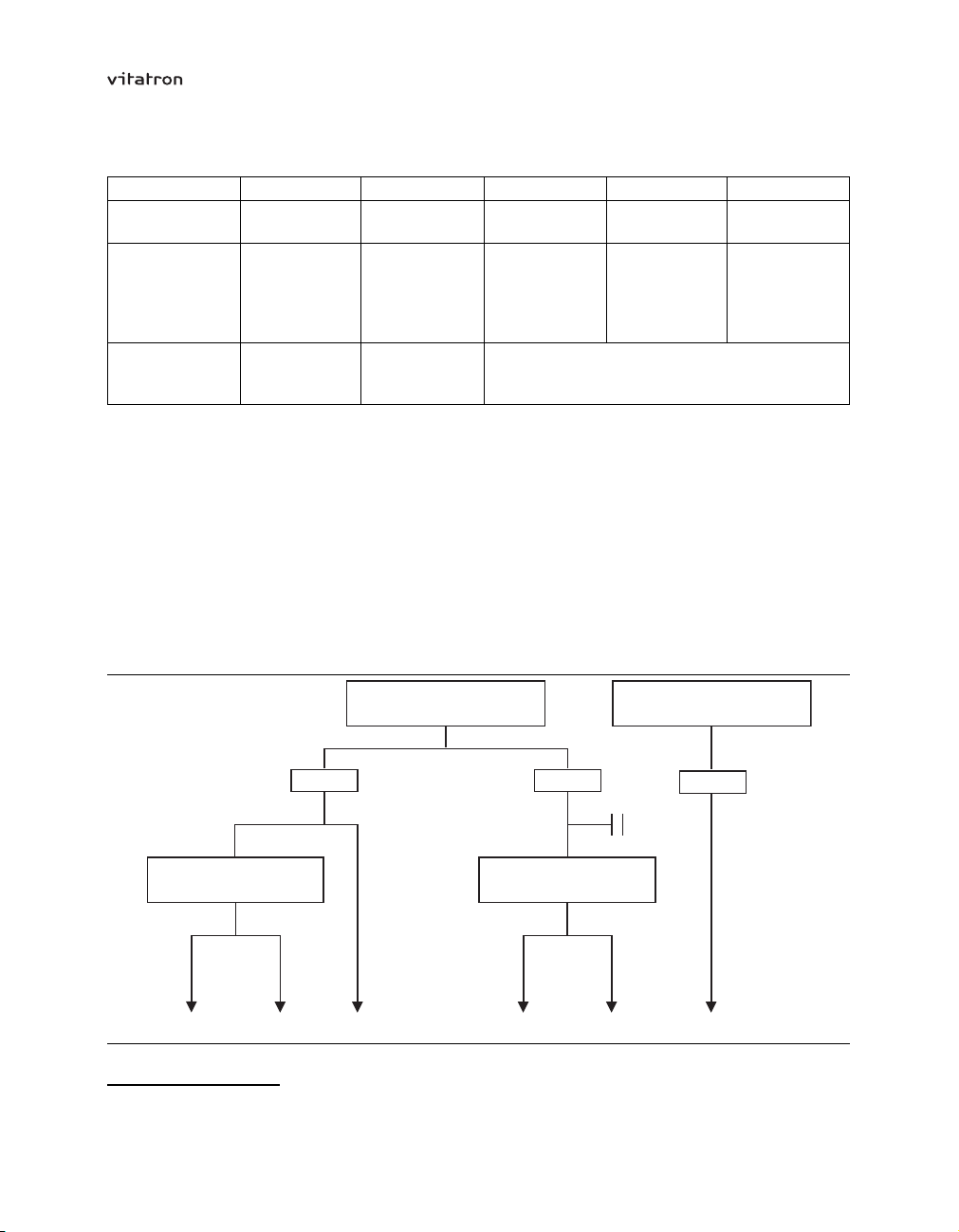
3.5 Pacing code
Pacemaker modes are described using the NBG code. The five-letter NBG1code,
named after The North American Society of Pacing and Electrophysiology (NASPE)
and the British Pacing and Electrophysiology Group (BPEG), describes the operation
of implantable pulse generators. The NBG code, which supersedes the ICHD Code,
is described in Table 1.
14
Page 15
T-series Reference Manual Section 3.5
Permanent Atrial
Fibrillation/Flutter?
Sinus Node Dysfunction
VVIR
AV Block AV Block
Paroxysmal Atrial
Fibrillation/Flutter?
DDDR + MS DDD(R) AAI(R)
Y N
Paroxysmal Atrial
Fibrillation/Flutter?
DDDR + MS DDD/VDD
Y N
Y N
Y
AV Block
Y N
Y
Y
Table 1. The Revised NASPE/BPEG Generic Code for Antibradycardia Pacing
Position: I II III IV V
Category: Chamber(s)
Paced
O = None
A = Atrium
V = Ventricle
D = Dual
(A + V)
Manufacturers’
designation
S = Single
(A or V)
Chamber(s)
Sensed
O = None
A = Atrium
V = Ventricle
D = Dual
(A + V)
S = Single
(A or V)
Response to
Sensing
O = None
T = Triggered
I = Inhibited
D = Dual
(T + I)
Rate
Modulation
O = None
R = Rate
modulation
Multisite
Pacing
O = None
A = Atrium
V = Ventricle
D = Dual
(A + V)
only:
Note: The programmer displays A or V (not S) for chambers paced and sensed.
3.6 Mode selection decision tree
The following basic decision tree is an aid in selecting the best pacing mode for a
particular patient.
Figure 2. Basic decision tree (from den Dulk, K et al. Selection of the optimal pacing mode. The
Netherlands Journal of Cardiology 1992; 5:214-225)
1
Bernstein A.D, et al., The Revised NASPE/BPEG Pulse Generator Code, Pace, 25, No 2, Feb 2002.
15
Page 16

T-series Reference Manual Section 3.7
3.7 Mode descriptions, indications and contraindications by mode
3.7.1 DDDR mode
The pacemaker senses and paces in both the atrium and the ventricle. Sensed atrial
events inhibit the atrial channel and start an AV delay. Sensed atrial events conducted to
the ventricles before the end of the AV delay inhibit the ventricular channel. Sensed atrial
events not conducted before the end of the AV delay trigger the release of a ventricular
stimulus (tracking of the atrial rate).
Paced atrial events also start an AV delay. Paced atrial events conducted to the ventricles
before the end of the AV delay inhibit the ventricular channel. Paced atrial events not
conducted before the end of the AV delay trigger the release of a ventricular stimulus.
In the absence of sinus rhythm and spontaneous AV conduction, both chambers are
paced at the sensor rate, the Flywheel rate, or the lower rate (whichever is highest).
In the presence of atrial tachyarrhythmias, Beat-to-Beat mode switching is initiated (the
ventricular rate is stabilized by rate responsive ventricular pacing). The atrial rate is
monitored on a beat to beat basis and AV synchronous pacing is restored as soon as
possible.
Indications:
chronotropic incompetence due to atrial bradyarrhythmia or AV block
•
sick sinus syndrome, including brady-tachy syndrome
•
paroxysmal atrial arrhythmias in patients who require restoration of AV synchrony
•
Contraindications:
permanent atrial tachyarrhythmias, including atrial fibrillation and flutter
•
expected aggravation of clinical symptoms (for example angina pectoris) or
•
congestive heart failure caused by fast heart rates
3.7.2 DDD mode
The pacemaker senses and paces in both the atrium and the ventricle. Sensed atrial
events inhibit the atrial channel and start an AV delay. Sensed atrial events conducted to
the ventricles before the end of the AV delay inhibit the ventricular channel. Sensed atrial
events not conducted before the end of the AV delay trigger the release of a ventricular
stimulus (tracking of the atrial rate).
16
Page 17

T-series Reference Manual Section 3.7
Paced atrial events also start an AV delay. Paced atrial events conducted to the ventricles
before the end of the AV delay inhibit the ventricular channel. Paced atrial events not
conducted before the end of the AV delay trigger the release of a ventricular stimulus.
In the absence of sinus rhythm and spontaneous AV conduction both chambers are
paced either at the Flywheel rate or the lower rate (whichever is highest).
In the presence of atrial tachyarrhythmias, Beat-to-Beat mode switching is initiated. The
atrial rate is monitored on a beat to beat basis and AV synchronous pacing is restored as
soon as possible.
Indications:
intermittent or complete AV block with normal sinus rhythm
•
sick sinus syndrome, including brady-tachy syndrome
•
paroxysmal atrial arrhythmias in patients who require restoration of AV synchrony
•
Contraindications:
permanent atrial arrhythmias, including atrial fibrillation and flutter
•
expected aggravation of clinical symptoms (for example angina pectoris) or
•
congestive heart failure caused by fast heart rates
3.7.3 DDIR mode
The pacemaker senses and paces in both the atrium and the ventricle. Atrial inhibition
does not trigger an AV delay. In the absence of spontaneous conduction to the ventricle
the pacemaker actively resynchronizes the atrium with the ventricle using an atrial
synchronization pace (ASP). The pacing rate is dictated by the sensor rate.
Indications:
atrial bradyarrhythmia in patients with paroxysmal atrial tachyarrhythmias, with or
•
without normal AV conduction
brady-tachy syndrome
•
17
Page 18

T-series Reference Manual Section 3.7
Contraindications
complete AV block with normal sinus rhythm (allows retrograde P-wave sensing or
•
continuous atrial synchronization pacing)
3.7.4 DDI mode
The pacemaker senses and paces in both the atrium and the ventricle. Atrial inhibition
does not trigger an AV delay. In the absence of spontaneous conduction to the ventricle
the pacemaker actively resynchronizes the atrium with the ventricle using an atrial
synchronization pace (ASP). The pacing rate is dictated by the programmed lower rate.
Indications:
atrial bradyarrhythmia in patients with paroxysmal atrial tachyarrhythmias, with or
•
without normal AV conduction
brady-tachy syndrome
•
Contraindications
complete AV block with normal sinus rhythm (allows retrograde P-wave sensing or
•
continuous atrial synchronization pacing)
3.7.5 DOO mode
The pacemaker provides asynchronous, AV sequential pacing at the programmed lower
rate.
Indications:
intended primarily as a temporary mode to reduce the likelihood of triggering or
•
inhibition during electrosurgery or electromagnetic interference
Contraindications:
intrinsic cardiac activity at a rate sufficient to cause competitive pacing
•
3.7.6 VDDR mode
The pacemaker senses in both the atrium and the ventricle but can only pace the
ventricle. It tracks spontaneous sinus rhythm and is inhibited by ventricular sensing.
In the absence of sinus rhythm, or in the presence of atrial tachyarrhythmias, rate
responsive ventricular pacing is initiated.
18
Page 19

T-series Reference Manual Section 3.7
Indications:
intermittent or complete AV block with normal sinus rhythm, with or without
•
paroxysmal atrial tachyarrhythmia
Contraindications:
likelihood of loss of AV synchrony (atrial bradyarrhythmia) and associated
•
complications (retrograde conduction, anticipated or known pacemaker syndrome)
permanent atrial tachyarrhythmias, including atrial fibrillation and flutter
•
expected aggravation of clinical symptoms (for example angina pectoris) or
•
congestive heart failure caused by fast heart rates
inadequate intracavitary atrial complexes
•
3.7.7 VDD mode
The pacemaker senses in both the atrium and the ventricle but can only pace the
ventricle. It tracks spontaneous sinus rhythm and is inhibited by ventricular sensing. In
the absence of sinus rhythm, or in the presence of atrial tachyarrhythmias, ventricular
(VVI) pacing at the programmed lower rate is initiated.
Indications:
intermittent or complete AV block with normal sinus rhythm, with or without
•
paroxysmal atrial tachyarrhythmia
Contraindications:
likelihood of loss of AV synchrony (atrial bradyarrhythmia) and associated
•
complications (retrograde conduction, anticipated or known pacemaker syndrome)
permanent atrial tachyarrhythmias, including atrial fibrillation and flutter
•
inadequate intracavitary atrial complexes
•
3.7.8 VVIR mode
The pacemaker senses and paces in the ventricle and is inhibited by sensed ventricular
events. In the absence of spontaneous ventricular rhythm, rate responsive ventricular
pacing is initiated.
19
Page 20

T-series Reference Manual Section 3.7
Indications:
permanent atrial fibrillation and flutter with symptomatic ventricular bradyarrhythmia
•
Contraindications:
expected aggravation of clinical symptoms (for example angina pectoris) or
•
congestive heart failure caused by fast heart rates
anticipated or known pacemaker syndrome
•
a need for the restoration of AV synchrony
•
3.7.9 VVI mode
The pacemaker senses and paces in the ventricle and is inhibited by sensed ventricular
events. In the absence of spontaneous ventricular rhythm, ventricular pacing at the
programmed lower pacing rate is initiated.
Indications:
permanent atrial fibrillation and flutter with symptomatic ventricular bradyarrhythmia
•
Contraindications:
anticipated or known pacemaker syndrome
•
a need for the restoration of AV synchrony
•
3.7.10 VVT mode
The pacemaker paces and senses in the ventricle. Operation is identical to the VVI mode
except that events sensed during the ventricular escape interval trigger an immediate
pacing pulse.
Indications:
intended as a temporary diagnostic mode, used to verify sensing and evaluate
•
arrhythmias. This mode may also be useful in preventing inappropriate inhibition in
the presence of electromagnetic interference.
Contraindications:
anticipated or known pacemaker syndrome
•
a need for the restoration of AV synchrony
•
20
Page 21

T-series Reference Manual Section 3.7
3.7.11 VOO mode
The pacemaker paces in the ventricle at the programmed lower rate (asynchronous
ventricular pacing). It is not inhibited by sensed ventricular events.
Indications:
intended primarily as a temporary mode to reduce the likelihood of triggering or
•
inhibition during electrosurgery or electromagnetic interference
Contraindications:
intrinsic cardiac activity at a rate sufficient to cause competitive pacing
•
3.7.12 AAIR mode
The pacemaker senses and paces in the atrium and is inhibited by sensed atrial events.
In the absence of spontaneous rhythm, rate responsive atrial pacing is initiated.
Indications:
atrial bradyarrhythmia with normal AV conduction
•
Contraindications:
AV conduction disturbances
•
atrial fibrillation and flutter
•
expected aggravation of clinical symptoms (for example angina pectoris) or
•
congestive heart failure caused by fast heart rates
inadequate intracavitary atrial complexes
•
3.7.13 AAI mode
The pacemaker senses and paces in the atrium and is inhibited by sensed atrial events.
In the absence of spontaneous atrial rhythm, atrial pacing at the programmed rate is
initiated.
21
Page 22

T-series Reference Manual Section 3.7
Indications:
atrial bradyarrhythmia with normal AV conduction
•
Contraindications:
AV conduction disturbances
•
atrial fibrillation and flutter
•
inadequate intracavitary atrial complexes
•
3.7.14 AAT mode
The pacemaker paces and senses in the atrium. Operation is identical to the AAI mode
except that events sensed during the atrial escape interval trigger an immediate pacing
pulse.
Indications:
intended as a temporary diagnostic mode, used to verify sensing and evaluate
•
arrhythmias. This mode may also be useful in preventing inappropriate inhibition in
the presence of electromagnetic interference.
Contraindications:
inadequate intracavitary atrial complexes
•
3.7.15 AOO mode
The pacemaker paces in the atrium at the programmed lower rate (asynchronous atrial
pacing). It is not inhibited by sensed atrial events.
Indications:
intended primarily as a temporary mode to reduce the likelihood of triggering or
•
inhibition during electrosurgery or electromagnetic interference
Contraindications:
intrinsic cardiac activity at a rate sufficient to cause competitive pacing
•
AV conduction disturbances
•
3.7.16 OOO mode
In the OOO mode pacing is switched off.
22
Page 23

T-series Reference Manual Section 3.7
Indications:
used for diagnostic purposes, such as the analysis of underlying rhythm
•
Contraindications:
patients with no underlying rhythm
•
23
Page 24

T-series Reference Manual
24
Page 25

T-series Reference Manual
4 The programmer
4.1 Introduction
Vitatron T-series pacemakers can be programmed with a Vitatron CareLink programmer
with Vitatron T-series software. This manual only describes the software for the Vitatron
T-series. For specific programmer information, please refer to the programmer manual
which is provided with the programmer.
This chapter describes how to carry out a follow-up session using the programmer.
how to start a programmer session (see Section 4.2)
•
how to use the cardiac dashboard (see Section 4.3)
•
how to view diagnostics (see Section 4.4)
•
how to program parameters (see Section 4.5)
•
how to start tests (see Section 4.6)
•
how to enter patient information (see Section 4.7)
•
how to save and reload data (see Section 4.8)
•
how to print and set print options (see Section 4.9)
•
Two sections describe how to change the programmer settings and display.
how to adjust the programmer (see Section 4.10)
•
how to adjust the ECG display (see Section 4.11)
•
The last section explains how to perform emergency programming (see Section 4.12).
Notes:
Programmers other than the Vitatron CareLink are not compatible.
•
When using a second programmer during the same follow-up session, the first
•
session must be ended before the second begins.
The screens in this chapter show examples based on dual chamber pacemakers,
•
and are subject to minor changes. The screens for single chamber pacemakers
have a simpler layout because many features are not applicable to all models.
25
Page 26

T-series Reference Manual Section 4.1
Warning: Pacemaker programming should be done only after careful study of
the Pacemaker Manual and after determination of the appropriate parameter
settings. Improper use of the programmer could result in erroneous or inadvertent
programming and improper operation of the telemetry and measurement functions.
4.2 How to start a programmer session
After switching the programmer on the Vitatron desktop appears.
Figure 3. The Vitatron desktop
The main parts of the desktop are described briefly in this section. The task bar, which
appears above the top line, is described in the programmer manual.
1 Top line – The desktop always shows the Vitatron logo on the top line. During a
follow-up session, the patient’s name, the pacemaker model name and number are also
shown. The top line is not usually included in the illustrations used in this manual.
26
Page 27

T-series Reference Manual Section 4.2
2 ECG window and controls – While the desktop is active, the ECG window displays
the default surface electrocardiogram (ECG lead I, II or III). During a follow-up session,
the filtered atrial and ventricular intracardiac electrograms (AEGM and VEGM), marker
annotations and marker intervals are also available. For a description of this window,
see Section 4.3.1.
The ECG controls on the right allow you to freeze the ECG, adjust the ECG settings
and ECG markers or recall previously stored ECGs. For a detailed explanation see
Section 4.11.
For instructions on connecting the ECG cable and leads, refer to the programmer manual.
3 Control panel – Pressing one of the control panel icons opens the relevant window in
the main window.
4 Main window – At startup the main window always contains the Select Model window.
During a follow-up session, the main window contains the cardiac dashboard or one
of the detailed windows.
5 Button line – When the desktop is active, the bottom line contains the [Auto Identify]
button and a Vitatron to Medtronic switch, which is used to go from Vitatron to Medtronic
applications and vice versa. During a follow-up or demonstration session, the bottom
line contains buttons that are available in all windows. On some buttons, three dots
indicate that pressing the button opens another window in which you can program
related parameters.
4.2.1 Starting a demo session
Select a model from the Select Model window and press [Demo] to start a simulated
programming session.
4.2.2 Starting a follow-up session
To start automatic pacemaker recognition position the programming head and press
[Auto Identify]. This starts initial interrogation of the pacemaker. The cardiac dashboard
appears in the main window (see Section 4.3). Press [Stop] to return to the Select
Model window.
The [Start] button can only be used to launch applications that are not started with auto
identify.
27
Page 28

T-series Reference Manual Section 4.2
Notes:
If the programmer is unable to identify the pacemaker the following message is
•
displayed: “Position programming head”.
In the unlikely event that more than one pacemaker is in close proximity to the
•
programming head, the programmer will warn you that more than one pacemaker
has been detected. The pacemakers are then listed and you are asked to select the
one to be interrogated.
4.2.3 Starting a reloaded data session
Select the “Programmer” icon and choose the reload session data option to reload
session data stored on diskette. For more information, see Section 4.8.3.
4.2.4 Starting the Analyzer program
If the Medtronic lead analysis software and hardware are installed on the programmer,
the Vitatron desktop will contain the “Analyzer” icon. Clicking the icon starts the analyzer
program. After ending the analyzer program the programmer restarts the Vitatron
software. For more information about the analyzer please refer to the documentation
provided with it.
4.2.5 Adjusting programmer settings
Select the “Programmer” icon to change the programmer time and date, audio or printer
options, turn the Therapy Advisor on or off, manage memory contents files or check the
software version. See Section 4.10 for more information.
4.3 How to use the cardiac dashboard
When the pacemaker has been identified with [Auto Identify], the programmer starts
initial interrogation of the pacemaker. When pacemaker interrogation is complete
(indicated by a progress bar), the cardiac dashboard appears. The cardiac dashboard
gives an overview of how the pacemaker has performed during the last follow-up period.
Therapy Advisor messages and the most important patient and pacemaker information
indicate whether the pacemaker may need reprogramming to optimize pacing therapy.
If you change pacemaker settings or measurements during the follow-up session, the
cardiac dashboard is updated.
You can select the “Dashboard” icon at any time to return to the cardiac dashboard.
28
Page 29
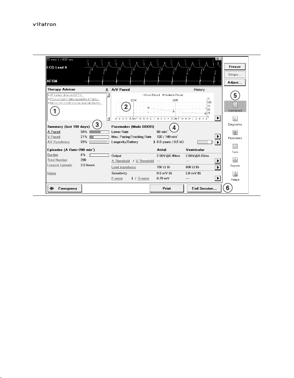
T-series Reference Manual Section 4.3
Figure 4. Cardiac dashboard window
1 Therapy Advisor window – The main Therapy Advisor messages are shown here,
if the Therapy Advisor is switched on. For a description of the Therapy Advisor, see
Section 7.2.
2 Dynamic window – Press one of the underlined hyperlinks on the cardiac dashboard
to display more detailed information in the dynamic window. If you press a Therapy
Advisor hyperlink, details and programming advice appear in this window. If you press
a parameter or diagnostic hyperlink, the dynamic window contains a graph showing its
history over the previous follow-up periods. The anticoagulation information in the Burden
graph comes from details entered in the Patient window.
The graphs are based on the History data in the pacemaker (see Section 6.8 and
Section 7.4.2). If any relevant parameter settings were changed between history periods,
no trend line will be shown on the graph.
3 Patient summary – This gives a summary of the most important pacing and sensing
data during the follow-up period, including notes from the Patient window. The Episodes
information applies to data collected during the follow-up period, and does not reflect any
episode trigger changes in the current follow-up session.
29
Page 30

T-series Reference Manual Section 4.3
4 Pacemaker information – This contains technical information on parameter settings,
battery and lead status, threshold and testing results. If no information is available, “---” is
displayed. If “***” is displayed, this means that no senses were detected during a test.
If you change any settings during the follow-up session, the cardiac dashboard will show
the new value. At initial interrogation, the P-wave amplitude is derived from the P-wave
amplitude histogram. If a P-wave amplitude test is carried out during the follow-up
session, the test result replaces the initial value. R-wave information is only available
after an R-wave amplitude test has been performed during the follow-up session.
5 Control panel – The control panel icons are used to access stored information and to
perform programming and test functions during a follow-up session.
6 Button line – During a follow-up session, the bottom line normally contains three
buttons:
The [Emergency] button is always active during a follow-up session. When pressed
•
it programs the pacemaker to emergency settings (see Section 4.12).
The [Print] button prints the data displayed in the current window (see Section 4.9.1).
•
The [End Session] button allows you to close the follow-up session (see
•
Section 4.3.2). There is also an option to save pacemaker data to diskette or the
network before closing the session.
Note: You cannot program parameters in this window. Select the “Parameters” icon to
change parameter values.
A number of symbols may appear on the cardiac dashboard or in diagnostics and
parameter programming windows (see Table 2).
Table 2. Programmer symbols
Symbol
Description
When pressed, shows more detailed information or the history of a parameter in
the dynamic window. The last hyperlink pressed changes from green to blue.
When pressed, leaves the cardiac dashboard and jumps directly to the relevant
diagnostic, test or therapy programming window.
When pressed, leaves the cardiac dashboard and jumps directly to the stored
EGM window of the first episode in the Selected Episodes diary.
30
Page 31

T-series Reference Manual Section 4.3
Table 2. Programmer symbols (continued)
Symbol
Description
Indicates the nominal (delivery) value of the parameter concerned.
Indicates the currently programmed value of the parameter concerned.
Indicates that more information is available. This information will appear if the
icon is pressed.
Indicates either a warning about possible undesirable interaction with other
parameters, or a caution about using an option. If the icon is pressed, it displays
an explanation of the warning or caution.
Warns that certain parameters are not programmable, or that certain values are
not allowed because of a conflict with other parameters.
4.3.1 The ECG window
During a follow-up session, the programmer can display recordings from up to seven
sources. The ECG leads I, II and III are always available and are detected via skin
electrodes, if the programmer is connected to these electrodes with the ECG cable.
Filtered atrial and ventricular EGMs (AEGM and VEGM) can be switched on and off
as desired. The Marker Annotation and Marker Intervals can be superimposed on an
ECG to facilitate interpretation.
For information on arranging the recordings and adjusting the ECG window display,
see Section 4.11.
The top left-hand corner of the ECG window shows the current heart rate (paced or
sensed) and the corresponding interval in milliseconds; this information is derived from
the ECG markers.
During tests, multiple recordings are displayed. The signals are the previously displayed
surface ECG combined with marker annotations and the intracardiac electrogram (EGM)
of the chamber being tested.
31
Page 32

T-series Reference Manual Section 4.3
Marker intervals – The programmer automatically measures the intervals between pace
and sense markers and displays them (in milliseconds) as a separate recording. For dual
chamber modes the AV intervals and the VV intervals are displayed. For single chamber
modes the AA or VV intervals are displayed, depending on the chamber being paced.
Marker annotation – Marker annotations depict pacemaker operation by showing events
as they occur. These annotations are intended to simplify ECG interpretation. Typically,
the Marker Annotation channel is superimposed on an ECG recording. Atrial events are
shown above the baseline and ventricular events below it.
Press [i] in the top right-hand corner of the window for an explanation of marker
annotations.
The following marker annotations are used:
Atrial events
•
– AP Atrial pace
– AS Atrial sense
– BS Atrial sense in blanking period
– PC Premature atrial contraction
– RC Retrograde atrial sense
– RS Atrial sense in refractory period
– SP Atrial synchronization pace
– TS Atrial tachy sense
– +P Triggered atrial pace
Ventricular events
•
– RS Ventricular sense in refractory period
– VE Premature ventricular contraction
– VP Ventricular pace
– VS Ventricular sense
– XP Ventricular safety pace
– +P Triggered ventricular pace
Note: Parameter programming or pacemaker interrogation may momentarily interrupt the
transmission of the EGM or marker annotations. This can result in missing markers on
the recording.
32
Page 33

T-series Reference Manual Section 4.3
4.3.2 Ending a follow-up session
To end a programming session press [End Session…].
If applicable a warning is given that programming has not been completed or that a
print job is still in process. A [Save Session…] option allows you to save pacemaker
information to a diskette (see Section 4.8.1). This makes it possible to do an “off-line”
analysis of the data by reloading the data at a later stage (see Section 4.8.3).
Confirm that you wish to end the session by pressing [End Now]. To continue with the
current programming session press [Cancel].
Applying the programming head to another pacemaker without switching the programmer
off or without pressing [End Session…] automatically opens the End Session window. If
the session is then ended you return to the Vitatron desktop, and all information stored in
the programmer memory is cleared.
Check the “Keep diagnostic data until next session” check box if you want to retain data
collected since the last follow-up session (which is otherwise automatically cleared one
hour after the programming session ends; see Section 7.3.1).
If the “Automatic SessionSync” check box is checked, the session data will be saved
on the network when you press [End Now]. For information on saving session data to
the network, see Section 4.8.2.
4.4 How to view pacemaker diagnostics
Select the “Diagnostics” icon to see the following tab options.
Rhythm Overview – This window contains an overview of pacemaker diagnostics and
gives access to histogram and Holter graphs containing more detailed information (see
Chapter 7).
Selected Episodes – This shows a summary of the main selected episode information
recorded during the collection period and gives access to more detailed information and
a stored EGM (see Chapter 8).
Sensor – This window shows how the accelerometer sensor has performed in the period
since the last follow-up session (see Section 7.8.2).
Battery – This option provides a remaining longevity estimate and measured battery
data (see Section 5.8.1).
33
Page 34
T-series Reference Manual Section 4.4
History – This option shows the most important pacing data and Selected Episodes from
the current follow-up period and up to five previous periods (see Section 7.4.2).
4.5 How to program parameters
The “Parameters” icon allows you to program pacing therapy parameters, program rate
response with Fast Learn, and choose settings for recording of Selected Episodes.
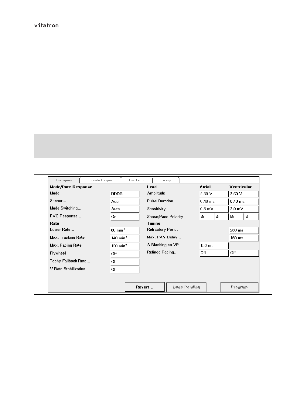
4.5.1 Programming therapy parameters
Parameters
⇒ Therapies
Figure 5. Therapies window
To program a parameter, for example, atrial amplitude, press the parameter value box
on the right of the parameter name. A value selection window appears. The currently
programmed value, for example, 2.50 V, is highlighted and followed by a boxed [P] (see
Figure 6).
34
Page 35

T-series Reference Manual Section 4.5
Figure 6. Selecting amplitude programming
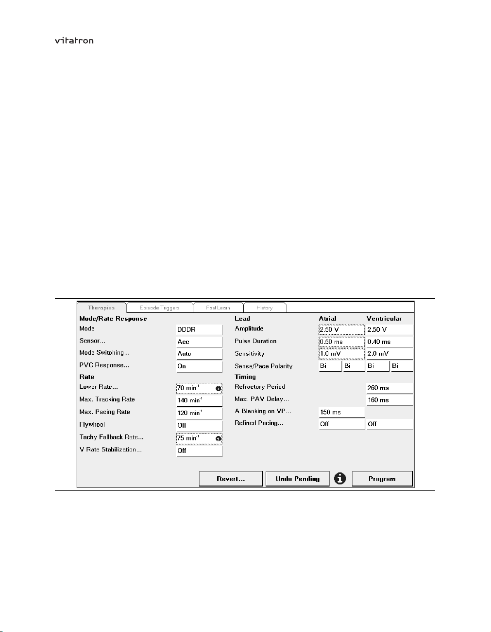
Select a new value, for example, 4.00 V. The value selection window closes. The new
value is boxed to indicate that it is pending and has not yet been programmed (see
Figure 7).
Figure 7. The chosen value is pending
35
Page 36
T-series Reference Manual Section 4.5
To program the new value, press [Program]. The box around the pending value
disappears.
Press [Undo Pending] to cancel the pending parameters.
If you open a value selection window and then decide not to select a new value, you can
close the window either by pressing [Close] or by pressing outside the window.
Some parameter names (for example, Mode Switching…) are followed by three dots.
This indicates that another window opens, in which you can program related parameters.
If one or more parameters are pending and you try to open another window, a warning
appears asking you to either program or cancel the pending values.
Batch programming – It is also possible to program several parameters in one batch.
To do this select a new value for each parameter you wish to program. All pending
parameter values are then boxed. Individual parameters can subsequently be changed
before final programming.
Figure 8. Batch programming
Now press [Program]. The values are unboxed, indicating that the corresponding
parameters have been reprogrammed. Press [Undo Pending] to cancel all pending
parameters.
36
Page 37

T-series Reference Manual Section 4.5
Note: If power to the programmer is unexpectedly lost, remove the programming head
from the pacemaker to cancel any temporary features and restore the pacemaker to its
permanently programmed state. Loss of power during permanent programming of a
parameter cancels the programming action. After the programmer is switched back on
and the appropriate application is started, the programming action must be repeated.
If power is lost before permanent programming of batched parameters can be completed,
all reprogramming is cancelled. All parameters then keep the values they had before
the batch programming was started. After the programmer is restarted, the batch
programming must be repeated.
If power is lost during a follow-up session, the start of session values in the programmer
memory are lost. When the programmer is restarted, the pacemaker is reinterrogated,
giving new start of session values.
Parameter pertinency – Only the parameter values applicable to a selected feature or
mode, for example, atrial amplitude in the AAI mode, are shown. This is called parameter
pertinency.
For example, if the pacemaker is in the DDD mode and the atrial amplitude is prepared
for reprogramming from 3.75 V to 2.50 V, the new value is boxed to indicate that it is
pending. If the mode is then changed to VVI, the boxed atrial value of 2.50 V disappears.
However, pressing [Program] results in permanent programming of both the VVI mode
and the atrial amplitude. Following any subsequent reprogramming to an atrial or dual
chamber mode the atrial amplitude will be 2.50 V.
Caution: If you select a pending value for any parameter and then select a new
mode, to which the parameter concerned is not pertinent, the pending value
disappears. However, it is still pending and will be permanently programmed if you
press [Program]. To prevent this, press [Undo Pending].
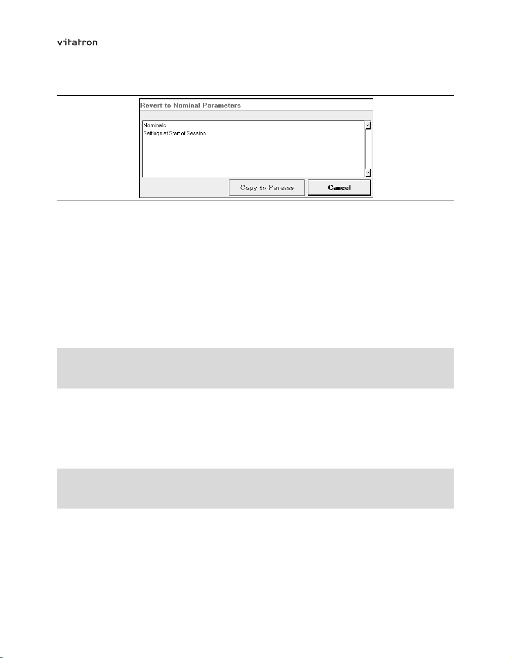
Nominal programming – Nominal programming is used to change all parameters to
nominal (delivery) values (refer to the product specifications in the appendices) or the
settings at the start of the follow-up session.
For nominal programming, press [Revert…] on the bottom left of the Therapies window.
37
Page 38
T-series Reference Manual Section 4.5
Figure 9. Revert to Nominal Parameters window
Now choose between “Nominals” and “Settings at Start of Session” and press
[Copy to Params]. The programmer returns to the Therapies window and all relevant
parameters are boxed showing their new values.
Press [Program] to change all relevant parameters to nominal settings or to the settings
at the start of the session. Press [Undo Pending] to cancel all pending parameters.
To cancel individual pending parameters select the relevant value box and press
[Undo Pending]. In both cases the pending values are then unboxed.
4.5.2 Programming Selected Episodes
Parameters
⇒ Episode Triggers
See Section 8.3 for details of how to choose the episode type and how to set up episode
recording.
4.5.3 Programming Fast Learn
Parameters
⇒ Fast Learn
Fast Learning adjusts the activity slope to optimize rate responsive pacing (see
Section 12.5).
38
Page 39

T-series Reference Manual Section 4.5
4.5.4 Viewing parameter history
Parameters
⇒ History
Parameter history shows the settings of therapy parameters at the start of the current
follow-up session and the previous session.
Notes:
If you change any parameters that affect sensing during the follow-up session, the
•
parameter history data from the previous session is cleared from the pacemaker
after the session. Sensing parameters include mode, atrial and ventricular
sensitivity, sensing polarity, refractory periods, blanking, and Selected Episodes
trigger and detection criteria.
If the Selected Episodes trigger is “Off” at the start of the follow-up session, no
•
parameter history data will be displayed.
4.6 How to start tests
Select the “Tests” icon to see the following tab options.
Threshold – This option allows you to carry out pulse amplitude and pulse duration
threshold tests, which can be used to optimize pacing conditions (see Section 6.2.3).
Sensing – This tab gives access to P-wave and R-wave amplitude tests, which can be
used to optimize sensing conditions (see Section 6.3).
Lead – This option allows you to measure lead impedance, to check the stability of
leads (see Section 6.4).
VA Interval – This option allows you to start a manual or automatic VA interval
measurement, to help in detecting retrograde conduction and far-field R-wave (FFRW)
sensing (see Section 6.5).
Temporary – This option allows you to set pacemaker programmers temporarily, to test
the effects of new settings on pacing (see Section 6.6).
39
Page 40
T-series Reference Manual Section 4.6
Atrial Burst Pacing – This option allows you to attempt to end an atrial tachyarrhythmia
or determine the Wenckebach point (see Section 6.7).
History – This tab shows the results of lead impedance measurements and the results
of threshold and sensing tests that have been carried out during the current follow-up
period and up to five previous periods (see Section 6.8).
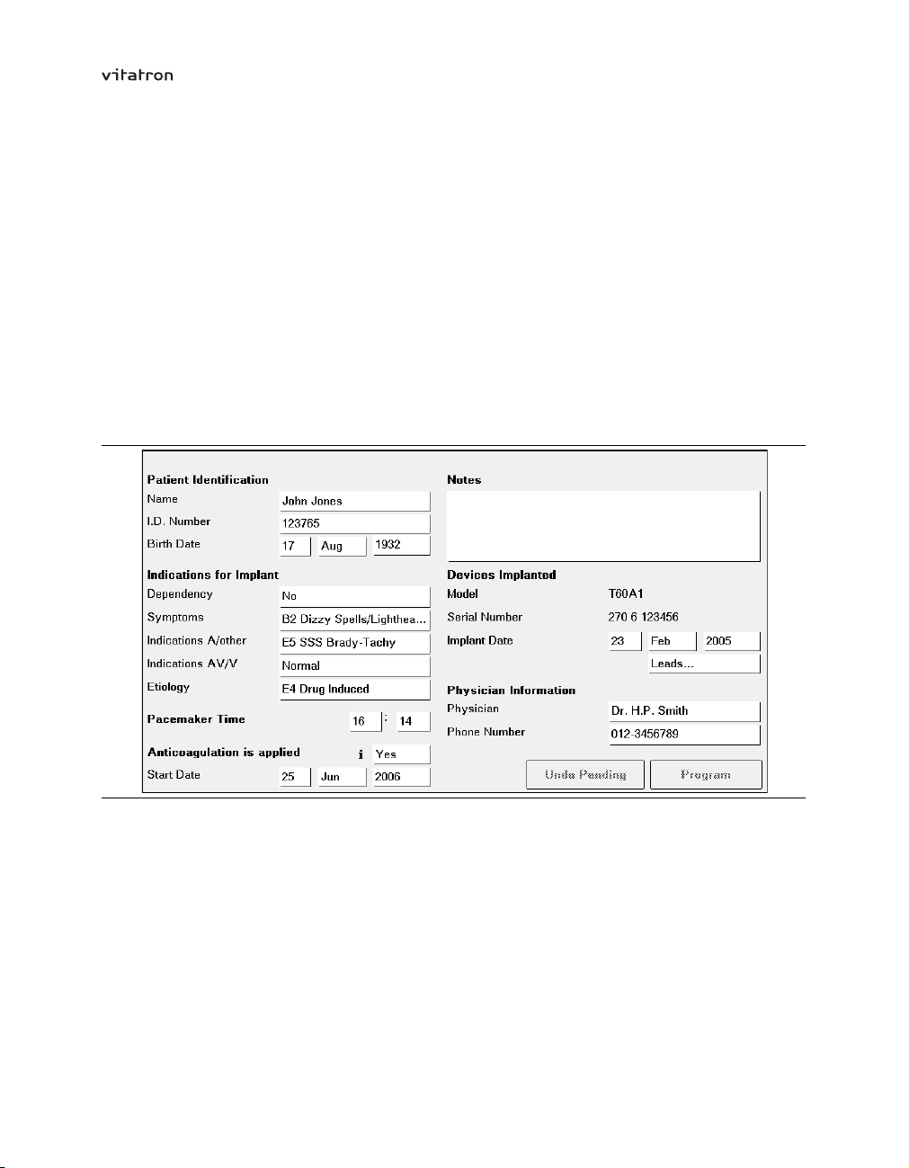
4.7 How to enter patient information
To enter patient data and pacing system information into the pacemaker, select the
“Patient” icon.
Figure 10. Patient window
Patient identification – To enter the patient’s name and ID number, press the
corresponding value box. You can now enter the patient’s name and ID number (both will
accept a maximum of 20 characters) using the on-screen keyboard.
When using the on-screen keyboard press the appropriate characters to select them.
Use the backspace key [<-] to delete the last entered character (you can also delete
characters by selecting them with a sliding movement of the touch pen and then pressing
the backspace key).
40
Page 41

T-series Reference Manual Section 4.7
Confirm the patient’s name or code by pressing [Enter] or press [Cancel] to leave the
window without programming a name or code. A confirmed name or code is boxed in
the value box, indicating that it is pending.
To enter the patient’s date of birth, press the appropriate value boxes for day, month
and year and then select the correct dates.
Indications for implant – A number of boxes are provided to enter the following
information:
(pacemaker) dependency (yes or no)
•
symptoms
•
indications (atrial or other)
•
indications (AV or ventricular)
•
etiology
•
In the value boxes select the indication appropriate for the patient or select “Unspecified”.
Pacemaker time – Here you can alter the pacemaker time (24-hour clock) by pressing
the appropriate value boxes (hours and minutes) and selecting the correct values.
Be aware that changing the pacemaker time clears all diagnostic data stored in the
pacemaker memory. Diagnostic data collected before the change can still be displayed
during the current follow-up session.
Notes – This space is provided so that any additional notes may be added (with a
maximum of 80 characters).
Anticoagulation is applied – Here you can specify whether the patient is receiving
anticoagulation medication. If you select “Yes”, you can enter the date when
anticoagulation treatment started.
Devices implanted – The programmer automatically displays the pacemaker model
number, serial number and implant date. The implant date can be changed by the user.
Leads – Press this value box to open a secondary window where you can enter the lead
manufacturer, model name, serial number and implant date for each lead.
Physician information – The physician’s name and phone number can be entered here.
Saving patient information – Press [Program] to enter data into the pacemaker. Press
[Undo Pending] to cancel entering patient or pacing system data.
41
Page 42

T-series Reference Manual Section 4.8
4.8 How to save and reload data
Session data files contain all data that has been interrogated during the follow-up
session. This includes device data at initial interrogation and all valid parameter data at
the moment the session data file was saved.
With a session data file, it is possible to do an “off-line” analysis of the data by reloading
the data from diskette at a later stage (see Section 4.8.3). The saved file can also be
used to organize and analyze patient and programmer information in the Medtronic
Paceart data management system.
The session data file also includes the contents of the pacemaker memory as read at
initial interrogation. This information can be useful for Vitatron specialists, in situations
where analysis of the pacemaker function is required.
Caution: Do not modify the session data file in other applications because the file
will become unreadable to Vitatron applications. Vitatron is not responsible for the
inappropriate use of data saved to diskette.
4.8.1 Saving pacemaker (session) data to disk
There are two ways to save session data to diskette. First insert a diskette into the
programmer disk drive.
End Session
⇒ Save Session...
⇒ Save
Reports
⇒ Save Session...
⇒ Save
The programmer automatically generates a file name using the current date and time
(see Figure 11).
42
Page 43

T-series Reference Manual Section 4.8
Figure 11. Save Session Data to Diskette window
Cautions:
Make sure only virus-free diskettes are used!
•
Remove the diskette from the disk drive before you turn the programmer off. Do
•
not switch the programmer on if a diskette is in the disk drive.
Keep the programming head and any other (electro)magnetic devices away from
•
diskettes; this may erase data stored on the diskettes.
4.8.2 Saving pacemaker (session) data to the network
You can send the saved session data through the SessionSync network connection. The
saved file can be used to organize and analyze patient and programmer information in
the Medtronic Paceart data management system.
To save session data to the network, press [End Session…]. If the “Automatic
SessionSync” check box is checked, the session data will be saved on the network
when you press [End Now]. The programmer automatically generates a file name using
the current date and time.
This option is only available if the programmer is configured with a SessionSync network
connection, and the SessionSync option is enabled in Programmer Preferences on the
Medtronic desktop. The network icon in the task bar indicates whether the SessionSync
option is available.
4.8.3 Reloading session data
Programmer (Vitatron desktop)
⇒ Reload Session Data
⇒ Reload Data
43
Page 44

T-series Reference Manual Section 4.8
You can reload session data that has previously been saved to diskette. This enables you
to perform the following actions:
Analyze (and compare) data from previous follow-ups.
•
Run demo follow-up sessions using different patient profiles.
•
Start the reload session data option from the Vitatron desktop. If necessary, press
[End Session] to return to the desktop. When you choose the “Reload Session Data”
option, you are asked to insert the relevant diskette into the programmer disk drive. The
programmer displays a list of all session export files stored on the diskette.
Figure 12. Reload Session Data window
Select the desired file and then press [Reload Data]. This loads the session data and
allows you to analyze the follow-up data or conduct a demo follow-up session.
44
Page 45

T-series Reference Manual Section 4.8
Figure 13. Example of a Reloaded Data Therapies window
Reloaded sessions can be identified by the text “Reloaded Data” in the top line and by
the fact that during a reloaded session ECG recordings are shown as a flat line. The
reloaded sessions only contain the data that was read out during initial interrogation of
the pacemaker. The results of any subsequent programming actions or measurements
carried out during the follow-up session are not displayed, although they are stored on
the diskette and can be accessed using commercially available software.
During a reloaded session you can simulate a follow-up session and analyze the data.
You can also “reprogram” pacing parameters; any changes may be reflected in the
information presented on the programmer or in reports during the reloaded session.
When you press [End] and return to the Vitatron desktop, all changes will be discarded.
You cannot change the contents of the file on the diskette.
4.8.4 Using memory contents files
In the case of programming difficulties, if the pacemaker behavior cannot be interpreted,
or if a pacemaker malfunction is suspected, the programmer often generates a memory
contents file on the programmer hard disk. The contents of this file enable Vitatron
45
Page 46

T-series Reference Manual Section 4.8
specialists to evaluate the pacemaker status and assist during follow-up. For information
on managing memory contents files, see Section 4.10.5.
4.9 How to print
You can print the current window, a report or the ECG recording on the built-in, thermal
strip printer, or on a full-size, external printer.
You can also choose a printer and adjust printing options (see Section 4.9.4).
Note: After printing data on the (thermal) strip printer Vitatron recommends that you make
photocopies of printed data (the quality of printing on thermal paper diminishes with time).
4.9.1 Using the Print button
In most windows, you can press the [Print] button to print the data currently displayed in
the window (the current page).
If the Print - Options window appears after you press [Print], you can choose whether to
print the current page or the full report for the current window (see Section 4.9.4).
Printing from the cardiac dashboard – If you press [Print] on the cardiac dashboard,
you can choose one or more reports from a list of cardiac dashboard reports.
Figure 14. Cardiac Dashboard print options window
4.9.2 Printing reports
Reports
⇒ Report Selection
46
Page 47

T-series Reference Manual Section 4.9
In the Report Selection window you can select reports to print, or define your own
standard set of reports to print at each session.
Figure 15. Report Selection window
The Report Selection window provides a list of all available reports (left) and selected
reports (right). The available reports include all the reports that have been generated
during the current session. For example, if you have performed a threshold test during
the current follow-up session, the Threshold Test report is available.
To add one or more reports to the list of selected reports, select the name in the available
reports list and press [--->]. To remove a report from the selected reports list, select
its name and press [<---].
Press [Print] to print the selected reports on the built-in or external printer.
You can save the set of selected reports for use in future follow-up sessions by pressing
[Save Set…]. In the Save Reports Preference window, select “New Report” (see
Figure 16). Give the new report set a name in the Name/Description value box, and
press [Save/Replace].
47
Page 48

T-series Reference Manual Section 4.9
Figure 16. Save Reports Preference window
4.9.3 Printing the ECG
To print the ECG using the built-in printer, press one of the print speed control buttons
on the left of the programmer keyboard. All three ECG lead recordings are then printed
at 12.5, 25 or 50 mm/s.
The print speed, which is shown when printing starts, can be changed with immediate
effect. This is shown on the printout by a dashed vertical line, followed by the new print
speed.
ECG marker annotations are included if they are switched on.
To stop printing, press the same print speed control button.
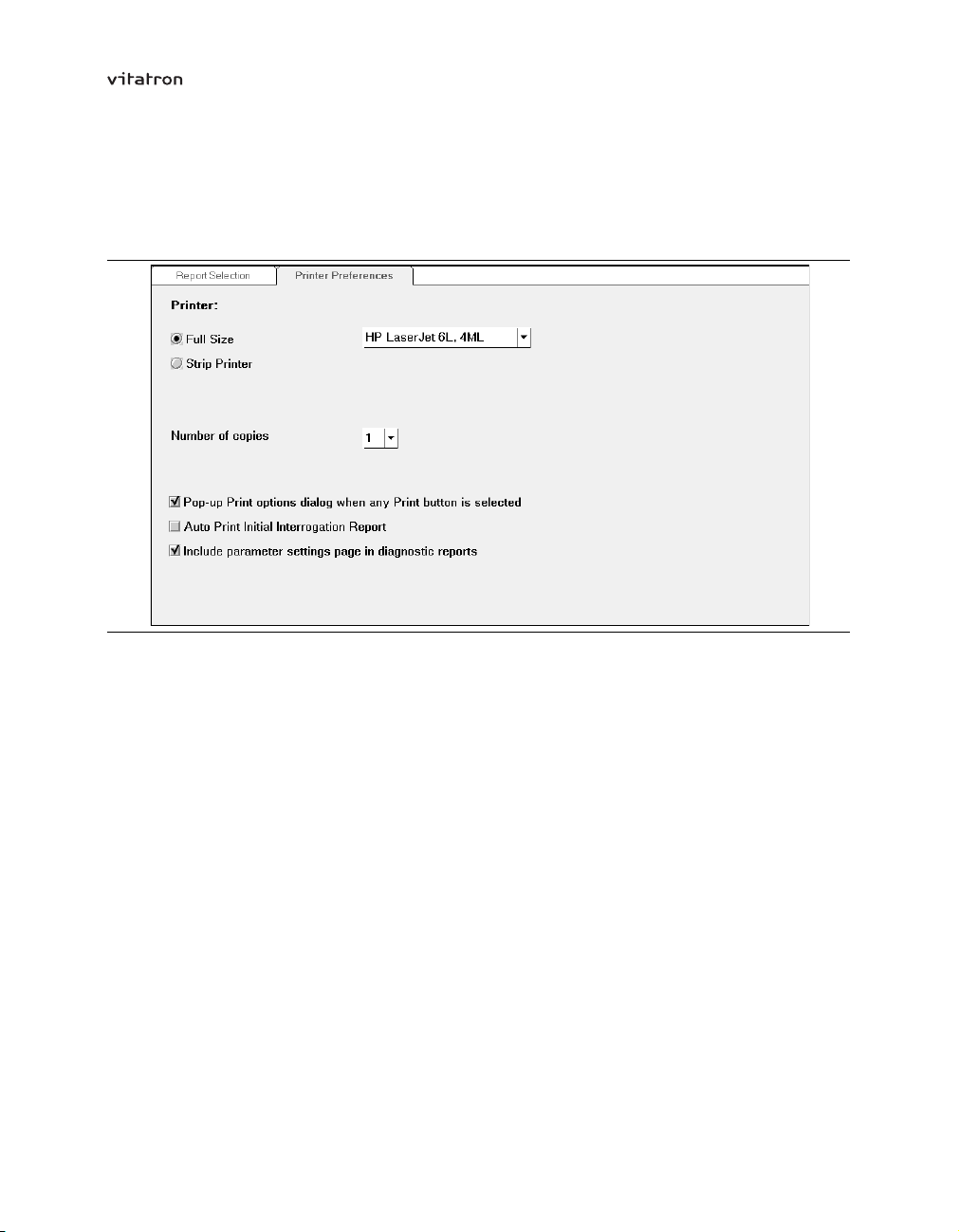
4.9.4 Choosing the printer and print preferences
Programmer (Vitatron desktop)
⇒ Programmer Preferences
Reports
⇒ Printer Preferences
48
Page 49
T-series Reference Manual Section 4.9
There are two ways to change the printer and print options: from the Vitatron desktop or
during a follow-up session. Both methods change the default settings for subsequent
programming sessions.
Figure 17. Printer Preferences window
You can adjust the following options:
Printer – Select the printer, which is either the built-in, thermal strip printer (the default
setting) or a full-size external printer. If you select the full-size printer you can choose the
printer from a drop-down list of all supported printer types.
Number of copies – Set the default number of copies to be printed.
Pop-up print options dialog – If you check this box, every time you press a [Print]
button, the Print - Options window will open. In this window you can overrule the
preference settings for a particular print job, and choose whether to print the current
page or a full report.
Auto print initial interrogation report – If this option is switched on (the default setting)
a full initial interrogation report is printed as soon as initial pacemaker interrogation is
complete.
Include parameter settings page – Check this box to add a list of relevant therapy
settings and the Selected Episodes settings to every full diagnostic report. This option is
not available from the Vitatron desktop,
49
Page 50

T-series Reference Manual Section 4.10
4.10 How to adjust the programmer
You can adjust programmer settings from the Vitatron desktop before you start a
follow-up session.
4.10.1 Changing the programmer time and date
Programmer (Vitatron desktop)
⇒ Time and date
The window displays the current time and date in the programmer (in the 24-hour clock
format).
Figure 18. Time and Date window
To change the programmer time or date, press the relevant value box and select the time
or date. Press [Apply] to apply the changes. Press another icon to leave the window
without making any changes.
Caution: The programmer clock is battery-powered so if the battery is depleted the
date and time will be incorrect and should not be used to set the pacemaker time. A
warning to this effect will be given by the programmer.
50
Page 51

T-series Reference Manual Section 4.10
4.10.2 Changing the programmer sounds
Programmer (Vitatron desktop)
⇒ Programmer Preferences
To mark certain events (for example, programming confirmed, start/end emergency, end
test, error) audible signals are used. The audio option allows you to switch the sound
on or off. To do this press the “Audio” value box and select the desired option (Off, Low,
Medium or High).
If the sound is switched off, only emergency beeps will still be audible. The last three
options are equivalent to “On” and do not provide different volume levels.
4.10.3 Changing the Therapy Advisor setting
Programmer (Vitatron desktop)
⇒ Programmer Preferences
Press the Therapy Advisor check box to switch the Therapy Advisor on or off.
4.10.4 Checking software release numbers
Programmer (Vitatron desktop)
⇒ Software
The Software window shows the version numbers and service release numbers of the
currently installed Vitatron software.
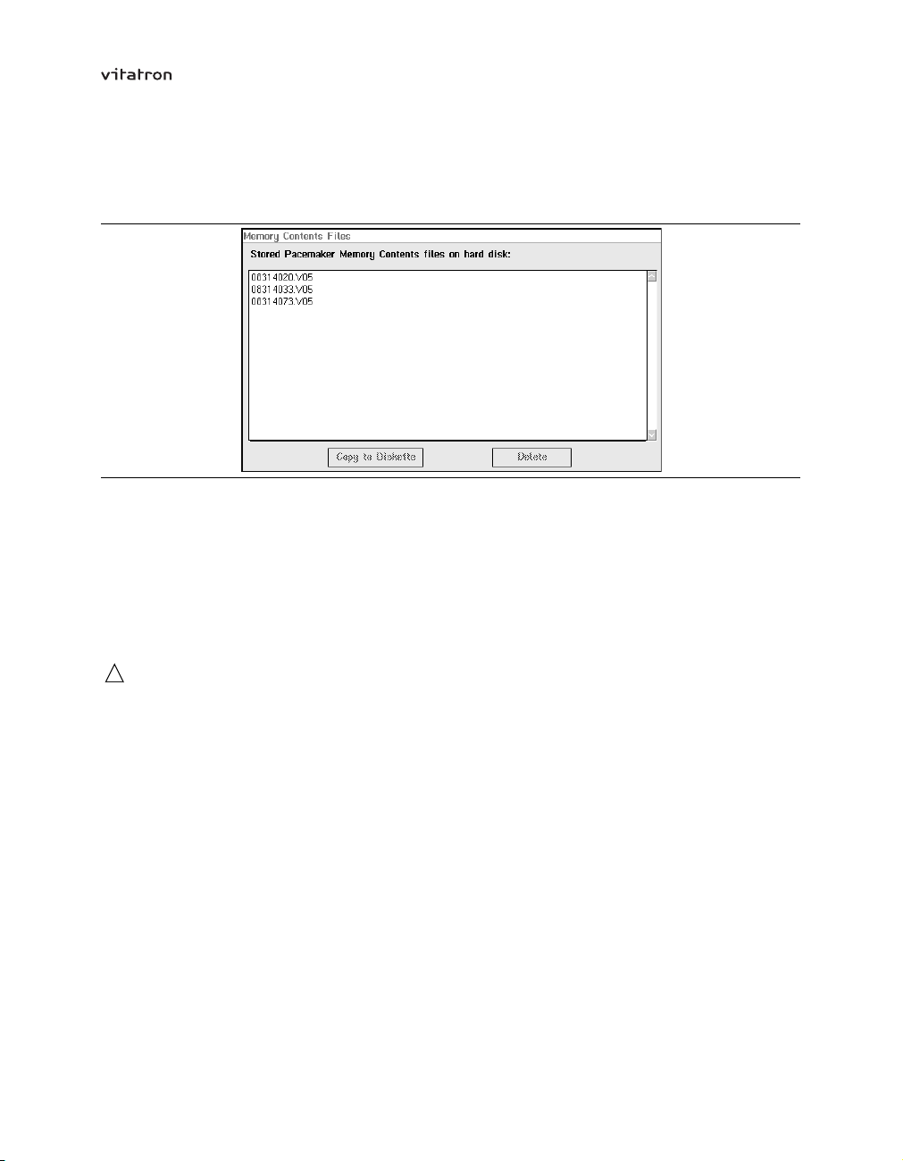
4.10.5 Managing memory contents files
Programmer (Vitatron desktop)
⇒ Memory Contents Files
51
Page 52
T-series Reference Manual Section 4.10
The Memory Contents Files window lets you copy pacemaker memory files (memory
dumps) from the programmer hard disk to diskette.
Figure 19. Memory Contents Files window
All stored pacemaker memory contents files are listed. Each file name starts with an
eight-digit number followed by a year code; if more than one file is listed the one with
the highest number is the newest for that particular year.
To copy a selected file from the programmer to a diskette, press [Copy to Diskette].
Use [Delete] to remove a selected file from the programmer.
Cautions:
Make sure only virus-free diskettes are used!
•
Remove the diskette from the disk drive before you turn the programmer off. Do
•
not switch the programmer on if a diskette is in the disk drive.
4.11 How to adjust the ECG window
4.11.1 Expanding the ECG window to full size
The ECG window automatically opens in the minimized format when the programmer is
switched on. To view all the available signals, you can expand the ECG window to its full
size using the square button in the upper-right corner of the ECG window. To return to
the partial-view window, press the square button again.
52
Page 53

T-series Reference Manual Section 4.11
Figure 20. Displayed recordings
4.11.2 Arranging the ECGs
You can arrange the ECG recordings in any order, and you can superimpose the marker
annotation and marker intervals on an ECG to facilitate interpretation.
Use the touch pen to “drag” an ECG recording to the desired position. The example
below shows how to move the Marker Annotation recording from its position over Lead I
to a position over Lead II.
First decide which recording you want to reposition. If its name (in this case, Marker
Annotation) is not displayed, tap the name of the superimposed recording to display
the hidden name.
Figure 21. Select the ECG to be moved
Press and hold the touch pen against the name of the ECG you want to move.
Without lifting the touch pen, drag the box now appearing around the recording name
to the desired location.
53
Page 54
T-series Reference Manual Section 4.11
Figure 22. Move the ECG to its new location
When you have the box positioned where you want the ECG to appear, lift the touch
pen. If you are positioning one ECG over another, it will snap into position. To equalize
the spacing between the recordings in the new arrangement, press [Cleanup] in the
Adjust window.
4.11.3 Adjusting and configuring the display
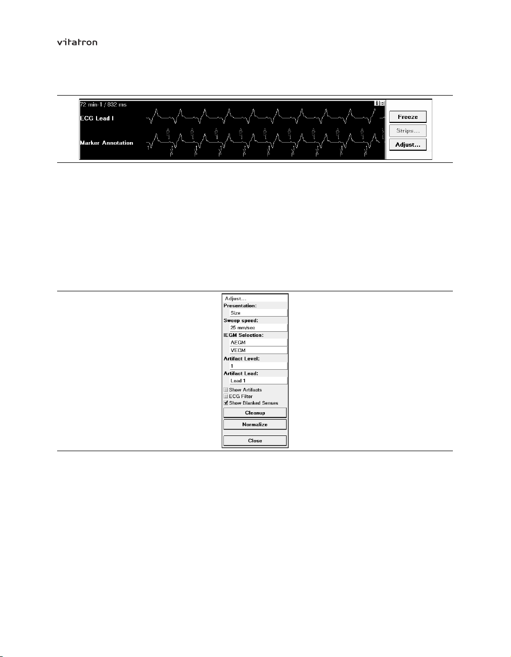
To change the ECG settings press [Adjust…] in the ECG control panel.
Figure 23. The Adjust window
The Adjust window contains controls that allow you to tailor the ECG display to your
specific needs.
Presentation: signal size – To adjust the size (or amplitude) of a signal select “Size” in
the Adjust window and alternately press and release the increase or decrease button to
change the size of the signal you want to adjust.
54
Page 55

T-series Reference Manual Section 4.11
Figure 24. Adjusting signal size
To return to the default setting, press [Normalize]. This resets the size of all recordings to
the default setting and equalizes the spacing between the recordings.
Presentation: ECG source – To change the order in which the recordings appear in
the window, select “Source” in the Presentation list. The source of the ECG is then
superimposed on the signal on a white background (see Figure 25).
Figure 25. Adjusting the source
Note that ECGs may be superimposed on one another (for example, when using marker
intervals or marker annotation). If this is the case the name of the source that is on top
appears. To display an underlying source and move it to the top, select the source name
on the left of the screen. The name changes to show the recording beneath it.
If you want to change the position of a superimposed signal, it must first be put on top so
that its name appears on the left of the screen (see Figure 26).
Figure 26. Changing the source
55
Page 56
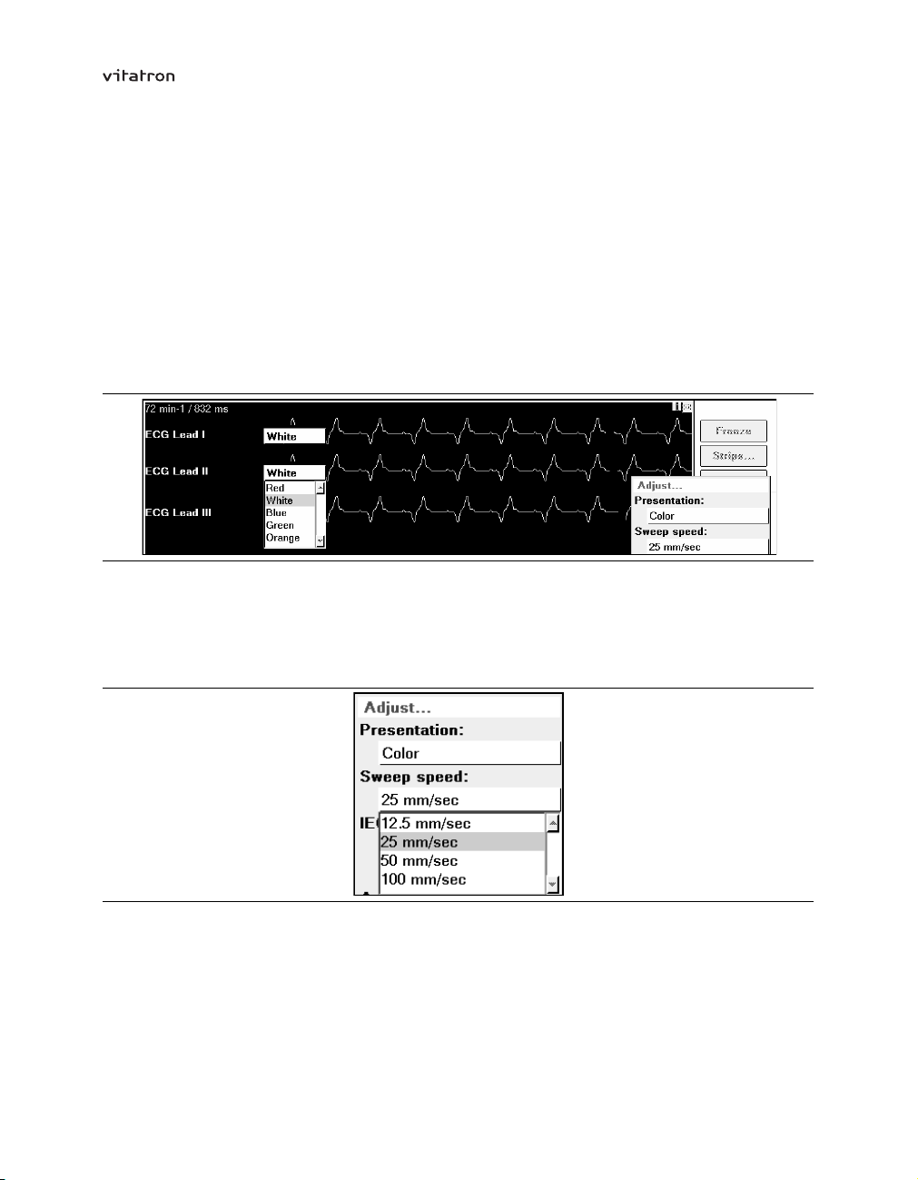
T-series Reference Manual Section 4.11
Now select the source for the ECG you want to change. A list appears displaying source
options. From this list select the desired source. Selecting a new source causes the
source of the recording presently displayed to change positions with the source you
selected.
Presentation: color coding – This changes the color of one or more of the recorded
signals. To change the color first select “Color” in the Adjust window.
Select the color field for the recording you want to change and from the list of options,
select the desired color.
Figure 27. Selecting the desired color
Sweep speed – By selecting “Sweep speed” from the Adjust window, you can set the
ECG sweep speed to 12.5, 25, 50, or 100 mm/s. The initial default setting is 25 mm/s, but
any change is saved and used as the default at the next follow-up session.
Figure 28. Selecting sweep speed
EGM selection – This feature lets you activate the atrial and ventricular EGMs, which
are displayed in the ECG window. The following options are available:
Off – no recording is displayed
•
AEGM - the filtered atrial EGM detected by the atrial lead
•
56
Page 57
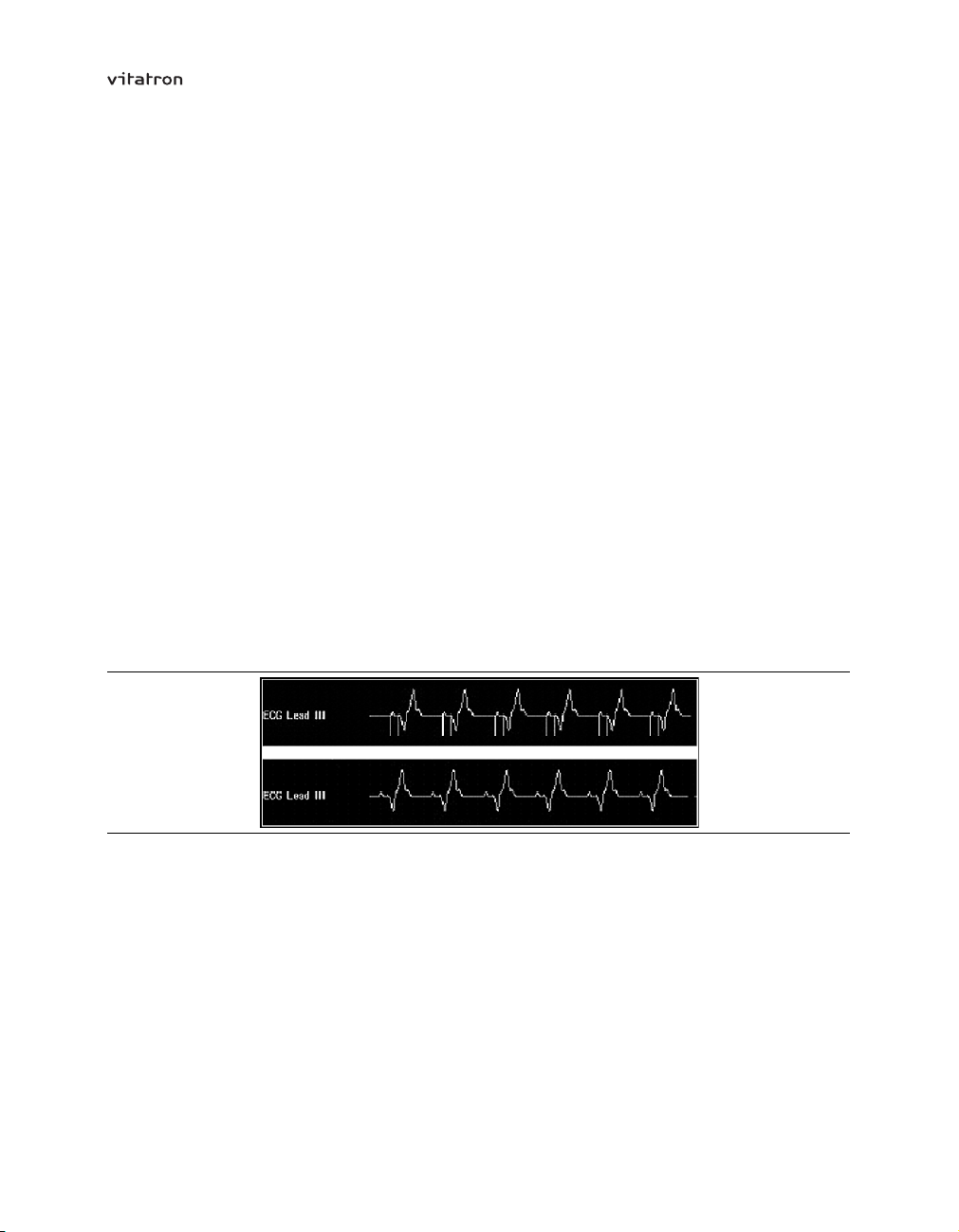
T-series Reference Manual Section 4.11
VEGM - the filtered ventricular EGM detected by the ventricular lead
•
Since the EGMs depend on information received from the pacemaker, they are not
displayed unless the programming head is positioned over the pacemaker. This feature is
not available if the pacemaker is recommended for replacement.
Artifact level – If “Show artifacts” is switched on, pacing spikes are shown in the ECG
window. The sensitivity to sensed pacing pulses can then be adjusted by changing the
artifact level. To prevent interference signals being interpreted as pacing pulses or to
prevent certain pacing pulses from being sensed you should select the appropriate
artifact level. The artifact level can range from 1 (very sensitive) to 5 (very insensitive).
The required artifact level may vary due to the amount of electromagnetic interference
(EMI) present at the follow-up site.
Artifact lead – This option determines which ECG lead is used to detect pacing pulses.
During programming and interrogation of the pacemaker, communication signals may
appear as artifacts on the ECG.
Show artifacts – Press the “Show Artifacts” check box to enable or disable pacing
artifact enhancement. A check mark indicates that it is enabled. The two ECGs in
Figure 29 show how an ECG appears with and without this feature enabled.
Figure 29. Artifact enhancement enabled (upper panel) and disabled (lower panel)
ECG filter – Press the “ECG Filter” check box to switch the ECG filter on or off. A check
mark indicates that the filter is switched on. In the presence of interference the filter may
improve the quality of both the displayed and printed ECG. The filter affects the ECG
detection bandwidth as follows:
Filter Off: bandwidth = 0.05 to 100 Hz
•
Filter On: bandwidth = 0.5 to 40 Hz
•
Show blanked senses – If this option is switched off (the check box is not checked)
blanked sensed atrial events are suppressed in the ECG recording. This allows you to
57
Page 58

T-series Reference Manual Section 4.11
avoid an overload of markers in the ECG recording during periods of high (sensed) atrial
rates. The option is switched on at the start of each new follow-up session.
Cleanup – Press this button to equalize the spacing between the recordings.
Normalize – Press this button to equalize the spacing between the recordings and to
adjust the size of each to the default setting.
Close – Press [Close] to leave the Adjust window.
4.11.4 Freezing and analyzing an ECG
This option lets you freeze the last 15 seconds of all ECGs displayed in the expanded
window. Press [Freeze] in the ECG control panel to open the frozen ECG viewing window.
Figure 30. Freezing an ECG
Using the on-screen calipers – The control buttons control the frozen ECG viewing
window by letting you move each of the two vertical cursors appearing in the window to
any desired position. The cursors thus act as calipers allowing you to measure the time
58
Page 59

T-series Reference Manual Section 4.11
interval between events. The caliper measurement is displayed in milliseconds in the
upper-left corner of the frozen ECG window.
Figure 31. Using the calipers
Alternately press and release the appropriate button to effect small movements, or press
and hold the button to effect larger movements.
Viewing other portions of the frozen ECG – Use the vertical scroll bar to scroll the
display up or down to view other ECGs. Touch and drag the box to scroll the strip up or
down. Tap the scroll up arrow or scroll down arrow to scroll the ECGs in small increments.
Use the horizontal scroll bar, which operates like the vertical scroll bar, to move the
display to the right or left to see other portions of the 15-second strip.
Saving a frozen ECG recording – You can save the frozen ECG by pressing [Save].
You may then recall the saved recording for later viewing or printing.
Printing the frozen strip – Press [Print] to print the frozen ECG recording you are
viewing (at 12.5, 25, 50, 100 or 200 mm/s).
Closing the frozen viewing window – Press [Close]. If you have not saved the
recording, a pop-up window will remind you to save or delete it.
59
Page 60

T-series Reference Manual Section 4.11
4.11.5 Recalling a saved ECG
Before ending a follow-up session, you can recall and view any ECG collected and saved
during the session. Such recordings may be those saved during a test (for example, the
threshold test) or an ECG saved following use of the Freeze option.
To view a previously collected ECG, press the [Strips…] button in the ECG control panel
or the [Strips…] button in the frozen ECG window. From the Other Strips window now
displayed, select the “Collected by programmer” option.
From the list of recordings in the selection field, select the one you want to view. It may
be necessary to use the scroll bar on the right of the field if there are more than five
recordings available.
To delete a saved recording, press [Delete]. This button is only active if you are viewing
a saved recording.
Press [Open].
4.11.6 Connecting an external ECG device
You can send analog output from the programmer to an external ECG device (such as
an ECG monitor, recorder or strip printer) through a cable box (which can be ordered
separately). For information on connecting the device, refer to the programmer manual.
During a follow-up session, the output is sent through four channels:
channel A sends the top ECG recording from the ECG window
•
channel B sends the top EGM recording from the ECG window (if EGM is selected
•
in the Adjust window)
channel C sends the lower EGM recording from the ECG window (if EGM is selected
•
in the Adjust window)
channel D sends the marker annotations
•
Calibrating the ECG – Press the calibration button on the cable box to generate
calibration signals for the ECG and the ECG markers. These signals are transferred to
the ECG window and, if applicable, to the built-in strip printer.
The calibration signals for the ECG consist of two pulses with an amplitude of 1 mV
and 5 mV respectively. Those for the ECG Markers consist of 8 pulses corresponding
to amplitude levels of -4 mV to +4 mV. These signals appear in the ECG window and
60
Page 61

T-series Reference Manual Section 4.12
the marker channel. You can use the signals to analyze the ECG and ECG marker
amplitudes by comparing them to the amplitude of the applicable calibration signal.
4.12 Emergency programming
If an error occurs, or if you make a mistake during programming, first try to correct it using
normal programming procedures. If this fails press [Emergency] on the programmer to
force the pacemaker to function with the emergency settings listed in Table 3. All other
pacing therapy parameters will be programmed to nominal (delivery) settings (refer to the
product specifications in the appendices). The programmer will stop all current activities
and restart the follow-up session by interrogating the pacemaker again. Diagnostic
data collection stops; diagnostic information is not lost, but remains in the programmer
memory.
As soon as the emergency settings have been programmed, the cardiac dashboard
appears and all functions are available. You should then reprogram the pacemaker to
settings appropriate for the patient.
Note: When programming emergency settings could cause battery depletion, the
programmer first programs the emergency settings, then gives a warning that higher
power consumption may reduce the time remaining before pacemaker replacement
is required. Vitatron recommends that you then decrease the output settings. If you
do not decrease output settings, see Section 5.8 for an explanation of the possible
consequences.
Table 3. Emergency settings
a
Mode
Lower rate 60 min
Pulse duration
Pulse amplitude 7.5 V 5.0bV
Sensitivity 2.0 mV 0.7 mV
Refractory period
Polarity (pacing and sensing) unipolar unipolar
a
Mode is VVI, except for single chamber pacemakers programmed to AXX mode.
b
Keeps value if greater than 5 V.
VVI AAI
–1
1.0 ms 1.0 ms
400 ms 400 ms
60 min
–1
Warning: For patients with a co-implanted implantable cardiac defibrillator (ICD),
emergency programming can lead to undesirable interaction with the ICD due to
unipolar pacing.
61
Page 62

T-series Reference Manual Section 4.12
Cautions:
Emergency programming initiated from Vitatron T-series software only works
•
with Vitatron T-series pacemakers.
Other Vitatron software applications cannot be used for emergency programming
•
of Vitatron T-series pacemakers.
62
Page 63

T-series Reference Manual
Part II
Follow-up and diagnostics
5 Follow-up
5.1 Introduction
The intention of this chapter is to offer post-implant and follow-up advice to the medical
personnel working with Vitatron pacemakers.
Follow-ups at regular intervals are required to check on the medical condition of the
patient and to confirm that the programmed parameter values are still appropriate.
Additionally, both the operation of the pacemaker and the condition of the battery require
regular monitoring.
The sections in this chapter are arranged as follows:
post-implant configuration (see Section 5.2)
•
record an ECG (see Section 5.3)
•
program patient information (see Section 5.4)
•
checks and programming (see Section 5.5)
•
optimizing the pacemaker (see Section 5.6)
•
the ECG/EGM (ElectroCardioGram/Intracardiac ElectroGraM) (see Section 5.7)
•
follow-up frequency and longevity (see Section 5.8)
•
63
Page 64

T-series Reference Manual Section 5.2
5.2 Post-implant configuration
During implant, the pacemaker configuration procedure starts automatically once the
pacemaker detects that a lead is connected. Note that even if the pacemaker is a dual
chamber device, the procedure begins as soon as the first lead is connected. A minimum
period of two hours is then required for the pacemaker to complete configuration.
If in the first two hours after implant, lead replacement or repositioning is necessary, then
the two-hour configuration period starts again. Vitatron advises you not to program the
pacemaker before implant as this could delay configuration. The pacemaker gives the
required pacing therapy at the delivery settings during the configuration period.
Once configuration is completed, the pacemaker program determines that implant is
complete and automatically programs the implant date. Programming the implant date
activates the diagnostic features and the pacemaker starts to collect diagnostic data. If
the implant date is set manually, the collection of diagnostic data starts one hour later.
Refer to Chapter 7 for a full description of the diagnostic features.
The first time a programming head is placed over the pacemaker after implant, the
programmer synchronizes the implant date in the pacemaker with the programmer date.
The pacemaker then starts recording selected episodes and stored EGM (see Chapter 8).
Note: Vitatron recommends that you check the pacemaker has set the implant date and
thus has switched on the collection of diagnostic data. If required, you have the option
to manually adjust the implant date (see Section 4.7). A time difference may appear in
diagnostic data collected before and after the date change.
5.3 Record an ECG
First, connect the patient to an ECG, either the built-in ECG or an external ECG monitor.
Then record and print out a copy of the ECG. During any programming session, either
post-implant or scheduled follow-up session, keep the ECG active to allow all cardiac
events to be continuously monitored.
As the post-implant ECG provides an important baseline record of the patient, Vitatron
recommends that you place a printout of the ECG in the patient’s file. This ensures
that a record is available for reference during the service life of the pacemaker. For the
same reason Vitatron recommends keeping a printout of the ECG recordings made at
each scheduled follow-up session.
64
Page 65

T-series Reference Manual Section 5.4
5.4 Program patient information
Select the “Patient” icon and then enter the patient and pacing system data in the Patient
window. For specific information on programming the data in this window, refer to
Section 4.7. This information, stored in the pacemaker, will throughout the service life of
the pacemaker allow you to perform the following tasks:
identify both the patient and the pacemaker system
•
retrieve information about diagnostic and implant information
•
retrieve information on the physician, implant center and the implant that is essential
•
for gathering further information
write comments, remarks and observations on a “notepad” and thus record
•
additional patient information or reminder notes for the next follow-up session. This
can prove especially useful when the patient files are not available.
5.5 Checks and programming
Vitatron suggests the following checks and programming after implant to ensure that the
pacemaker program meets the patient’s requirements.
During routine follow-up sessions, use this section to ensure that any patient changes
are recognized and met. If any help is required with programming, or for specific
programming instructions, refer to Chapter 4.
5.5.1 Interrogate the pacemaker
With the programmer head positioned over the pacemaker, use the cardiac dashboard
to assess the pacemaker status. Print out a copy of the cardiac dashboard summary
report (see Section 4.9.1). If applicable, print out the diagnostics, including the Holter
and the histogram data. Place all the printouts in the patient’s file so that a record is
available for analysis if required.
If the “Auto print initial interrogation report” option is checked in the Printer Preferences
window, the results of the initial pacemaker interrogation are printed automatically (see
Section 4.9.4).
65
Page 66

T-series Reference Manual Section 5.5
Note: As soon as the programmer head is correctly positioned the pacemaker switches
to its magnet pacing rate. This rate continues until either the interrogate button on
the programmer head or the [Auto Identify] button is pressed, and communication is
established. Then the magnet rate is switched off. In patients who experience discomfort
while the magnet rate is active, it is advisable to press the interrogate button before
positioning the programmer head. This limits the length of time during which the magnet
rate is active.
5.5.2 Confirm lead function
Check the lead impedance displayed on the cardiac dashboard. Compare the values
displayed on the screen with the values obtained at the last follow-up session.
5.5.3 Pulse amplitude and pulse duration threshold tests
Use the pulse amplitude and pulse duration threshold tests to determine the minimum
pulse amplitude and pulse duration, at which it is possible to obtain effective capture. If
required, see Section 6.2 for more detailed information on performing these tests. Adapt
the output values if necessary.
5.5.4 Rate response
The delivery setting is the non rate responsive mode.
If the patient requires rate responsive pacing, program the mode setting to the
appropriate rate responsive mode.
5.5.5 Mode switching
The delivery setting is “Fixed”.
There are two options available, “Fixed” and “Auto” (automatic). Unless the patient’s
medical condition dictates differently, Vitatron advises you to use the following settings.
In DDDR mode, ageing patients: program mode switching to “Auto” with mode
•
switching sensitivity set to “Standard”.
In DDDR mode, young patients: program mode switching to “Auto” with mode
•
switching sensitivity set to “Moderate”.
In VDDR mode, all patients: program mode switching to “Fixed” or “Auto”, with mode
•
switching sensitivity set to “Moderate”.
See Section 10.5 for further information on mode switching and mode switching sensitivity.
66
Page 67

T-series Reference Manual Section 5.5
5.5.6 Lower rate
The delivery setting is 60 min–1.
Use the patient’s medical condition to determine whether to keep the delivery setting, or
to use a more appropriate setting.
See Section 9.4 for further information on the lower rate parameter.
5.5.7 Maximum tracking rate
The delivery setting is 140 min–1.
Use the patient’s age and medical condition to determine whether to keep the delivery
setting, or to use a more appropriate setting. For further information, see Section 9.5.
5.6 Optimizing the pacemaker
Vitatron recommends that you perform the following pacemaker optimizing procedures,
both during the post-implant stage and at the subsequent follow-up sessions. These
procedures help to deliver the optimal pacemaker therapy to the patient and ensure a
long pacemaker lifetime.
5.6.1 Optimizing pacing
Having determined the thresholds, check that the pulse amplitude and pulse duration
are appropriate for the patient. When programming the pulse amplitude, as a generally
accepted standard Vitatron recommends that you program a safety margin of twice the
pulse amplitude threshold. When programming the pulse duration, Vitatron recommends
that you program a safety margin of three times the pulse duration threshold. Check that
the pacing polarity settings are appropriate. See Section 6.2 for detailed programming
instructions on optimizing pacing.
5.6.2 Optimizing sensing
First, check that the sensitivity is still at an appropriate setting for the patient. Then check
that the sensing polarity setting is correct. Following on from these checks, carry out
the P-wave and R-wave amplitude tests.
See Section 6.3 for detailed programming instructions on optimizing sensing.
67
Page 68

T-series Reference Manual Section 5.6
5.6.3 Diagnostics
If there are any significant changes, or if the patient has reported any problems, the
pacemaker diagnostic procedures can help to quickly locate the cause of the problem.
Refer to Chapter 7 and Chapter 8 for detailed information on using the pacemaker
diagnostics.
5.6.4 Atrial burst pacing
If the patient is suffering from atrial tachyarrhythmia during the follow-up session, atrial
burst pacing can be used to try to end the tachyarrhythmia. Atrial burst pacing can also
be used to determine the Wenckebach point. See Section 6.7 for detailed information on
atrial burst pacing.
5.6.5 Updating the patient’s file
When the required optimizing and diagnostic procedures are completed, Vitatron
suggests printing out all the data and saving it in the patient’s file. In addition, save the
information to disk (see Section 4.8.1) and place the disk in the patient’s file.
5.7 The ECG/EGM
At the beginning of each follow-up session, Vitatron recommends that you connect the
patient to either the built-in ECG, or an external ECG monitor. If you use the built-in ECG
it is possible to integrate the ECG information with other information from the pacemaker.
See Chapter 4 for a more detailed description.
EGM – This feature lets you obtain, display and view graphs of intracardiac signals on
the programmer screen. From the EGM information, you can determine the properties
of intracardiac signals such as amplitudes, intervals and rhythms. It is also possible to
use the information to determine if electromagnetic interference (EMI), far-field and
retrograde signals are affecting the intracardiac signals.
Note: The EGM display is only available when the programming head is in position
over the pacemaker.
5.8 Follow-up frequency and longevity
The follow-up frequency depends on the patient’s condition and the age of the pacemaker.
Use the following pacemaker information to determine the optimal follow-up frequency.
68
Page 69
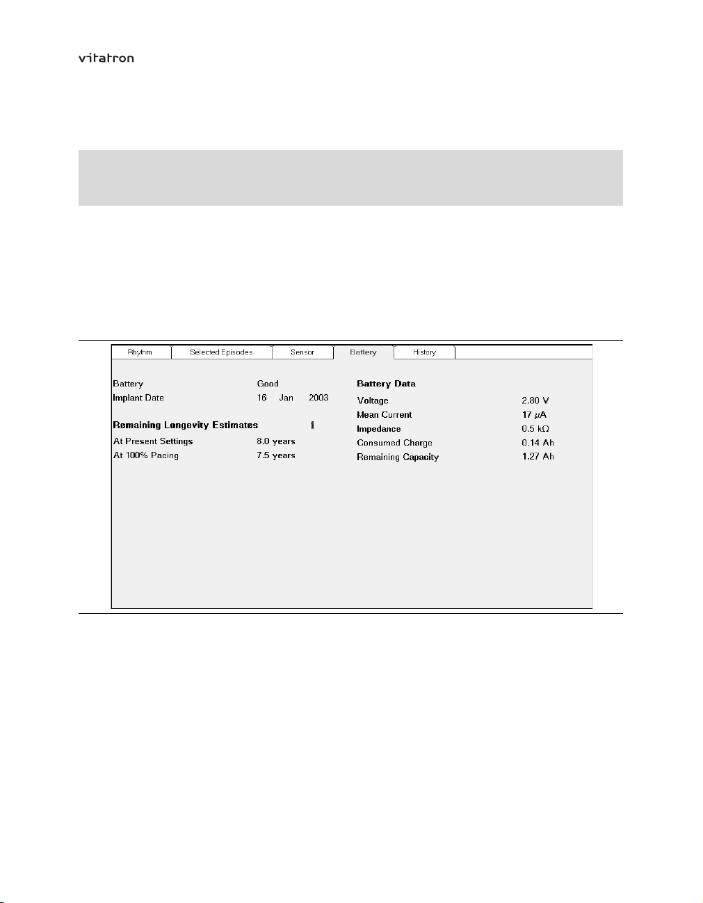
T-series Reference Manual Section 5.8
5.8.1 Pacemaker battery lifetime indicators
Diagnostics
⇒ Battery
The programmer calculates and displays pacemaker lifetime estimates on screen. Use
the Battery window to assess the remaining battery lifetime (see Figure 32). There is also
additional information on the battery, as well as other pacemaker information that can
affect the service life of the pacemaker under various conditions. From this information it
is possible to make an estimate of the time to the next follow-up session.
Figure 32. Battery window
The programmer calculates the estimated time until the recommended replacement time
(RRT) of the pacemaker. This estimation is based on the programmed settings and the
pacemaker recorded data. Although a small percentage of pacemakers may reach RRT
sooner than the remaining longevity estimate, the main purpose of the feature is as an
aid in estimating the appropriate follow-up session interval.
69
Page 70

T-series Reference Manual Section 5.8
Battery status and remaining longevity are dependent on the present settings of the
pacemaker. If any of the following remaining longevity critical parameters are pertinent
and if any or all of them are altered, the battery status can change:
mode
•
lower rate
•
pacing polarity (atrial or ventricular)
•
pulse amplitude (atrial or ventricular)
•
pulse duration (atrial or ventricular)
•
Ventricular Rate Stabilization
•
tachy fallback rate
•
Selected Episodes trigger
•
EGM recording
•
Notes:
Current consumption and remaining longevity are strongly influenced by changes
•
in mode, pacing rate, sensing (especially AF sensing), and therapies. Remaining
longevity is therefore not always accurately predictable, as it is highly dependent on
the patient/therapy interaction.
At high output settings it is possible that remaining longevity and remaining capacity
•
cannot be estimated accurately. In this case dashes (---) appear in the relevant fields.
When the pacemaker battery is maturing, changing a pacemaker setting to a value
•
that uses more current could result in the battery status changing, for example,
from ’Good’ to ’Ageing’ . Before accepting the change, note that there is then the
possibility of the pacemaker reaching ’Replace PM’ in less then six months at this
stage in the battery’s lifetime.
As a further aid to estimating the pacemaker lifetime, the calculated lifetime figures for
each model are shown (see Table 4 and Table 5).
70
Page 71

T-series Reference Manual Section 5.8
Table 4. Calculated lifetime (after 4 months shelf life)
Model Mode 2.5 V, 500 Ù
100% pacing 50% pacing 100%
–1
70 min
0.5 ms
Vitatron T60 DR DDDR
Vitatron T20 SR VVIR
Table 5. Calculated lifetime (after 18 months shelf life)
Model Mode 2.5 V 5.0 V
Vitatron T60 DR DDDR
Vitatron T20 SR VVIR
7.5 years
11.1 years 12.1 years 12.4 years 13.3 years 14.0 years
500 Ù 300 Ù 500 Ù
100% pacing 100% pacing 100% pacing
70 min–1, 0.5 ms 70 min–1, 0.5 ms 70 min–1, 0.5 ms
6.8 years 6.0 years 3.5 years
10.3 years 9.4 years 6.5 years
–1
60 min
0.4 ms
8.6 years 8.7 years 9.7 years 10.3 years
70 min
0.5 ms
–1
60 min
0.4 ms
–1
inhibited
70 min
0.5 ms
–1
Note: During periods in which the pacemaker senses high frequency atrial rhythms,
especially AF, there will be an increase in power consumption. This will result in a
reduction in battery lifetime. As an example, battery life could be reduced by 15% if the
pacemaker were to sense an AF rhythm of 300 min–1through 25% of the pacemaker
lifetime.
5.8.2 Follow-up intervals
Vitatron recommends that you schedule a follow-up session at least once a year, even
though the pacemaker memory can store more than a year’s diagnostics.
You can determine the recommended follow-up interval using information provided by the
programmer, or using a magnet, to monitor the battery.
Using the programmer – The follow-up intervals suggested in Table 6 are based on
the battery status and estimated longevity. The medical condition of the patient dictates
when to schedule the next follow-up session within the suggested follow-up interval.
Table 6. Follow-up intervals - using programmer
Battery status Remaining longevity
“Good” more than one year Dependent on the patient’s condition, up
“Good” more than six months Dependent on the patient’s condition, up to
a
Suggested follow-up interval
to one year.
six months.
71
Page 72

T-series Reference Manual Section 5.8
Table 6. Follow-up intervals - using programmer (continued)
Battery status Remaining longevity
a
Suggested follow-up interval
“Ageing” less than six months Dependent on the patient’s condition, up
to three months.
b
“Replace PM”
a
At high output settings remaining longevity cannot be estimated accurately and is shown as “---”. In this
case, the follow-up interval should be less than 3 months.
b
The pacemaker has sufficient battery capacity to operate at reduced output settings for at least 90 days
after the battery status changes to “Replace PM” (see Section 5.8.3).
none
Schedule replacement of the pacemaker.
Using a magnet – Placing a magnet over the pacemaker switches the pacemaker to
fixed rate pacing magnet mode. Removing the magnet causes the pacemaker to revert to
the programmed settings. From the fixed pacing rates shown in Table 7 it is possible to
determine battery status without using the programmer.
Warning: In magnet mode the pacemaker operates in an asynchronous pacing
mode. If the intrinsic rate is higher than the magnet rate, this may induce ventricular
tachycardia or ventricular fibrillation.
Table 7. Follow-up intervals - using magnet
Magnet pacing
rate
100 min
–1
(600 ms)
–1
95 min
(630 ms)
–1
86 min
(700 ms)
–1
90 min
(670 ms)
a
At high output settings the follow-up interval should be less than three months.
b
The pacemaker has sufficient battery capacity to operate at reduced output settings for at least 90 days
after the battery status changes to “Replace PM” (see Section 5.8.3).
Battery status and pacemaker
restore Suggested follow-up interval
a
“Good” Dependent on the patient’s condition, up
to six months.
“Ageing” Dependent on the patient’s condition, up
to three months.
“Replace PM”
b
Schedule replacement of the pacemaker.
“Partial restore” Refer to Appendix A for information on
how to proceed once a “partial restore”
has occurred.
5.8.3 Pacemaker replacement
During the initial interrogation, if the pacemaker determines that the battery status
appears to be “Ageing” or “Replace PM”, then a warning opens over the cardiac
dashboard. If available, the time when the status changed from good or ageing is also
indicated (see Figure 33).
72
Page 73
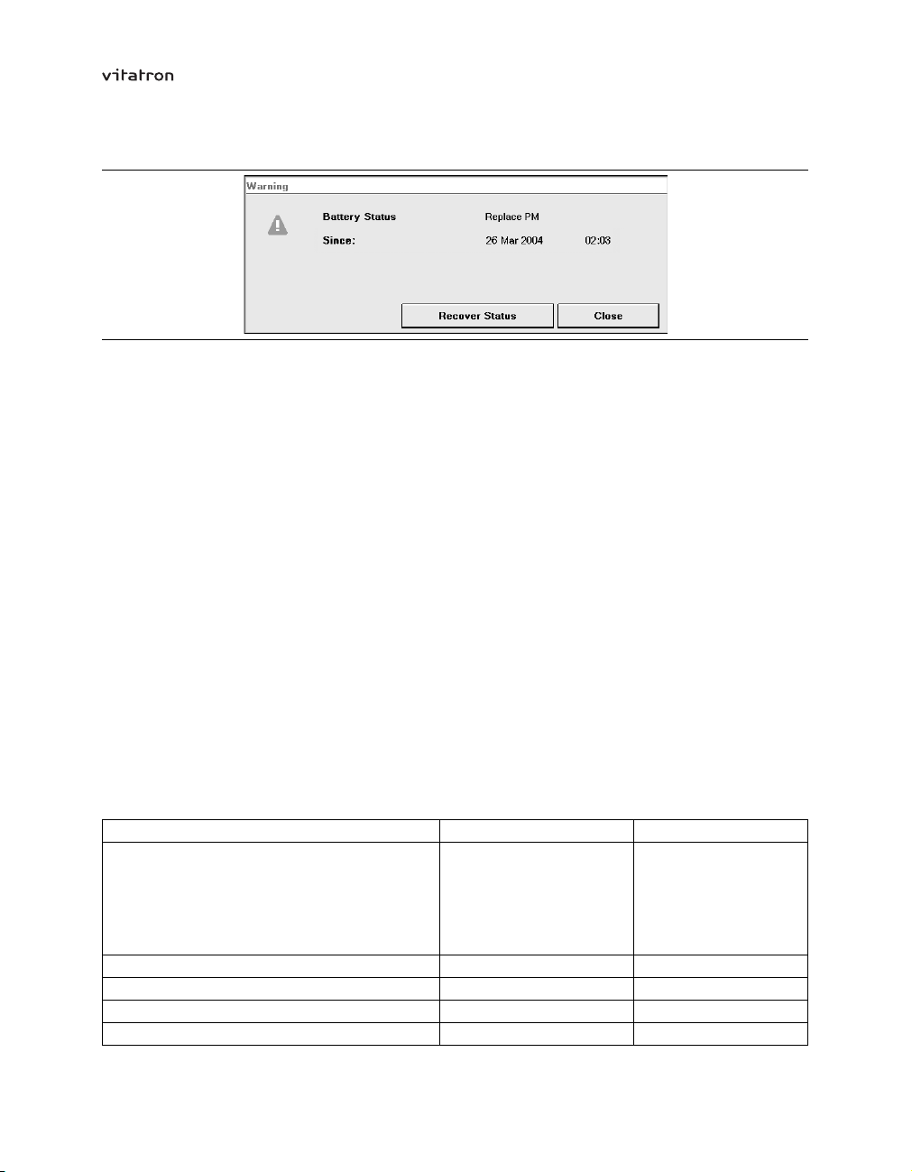
T-series Reference Manual Section 5.8
Figure 33. Battery warning
When the battery status indicates “Replace PM”, and the programmer determines
that recovery is possible, then the [Recover Status] button is displayed. Pressing
[Recover Status] resets the “Replace PM” indication to either “Ageing” or “Good”,
dependent on the current pacemaker settings.
Check the time when the status changed. The longer the time since the battery
status changed to “Replace PM”, the more urgent it is to replace the pacemaker. The
pacemaker settings and the battery impedance determine the battery status “Replace
PM”. At that moment when the pacemaker determines that the battery status reached
“Replace PM”, 99.9% of the pacemakers have sufficient battery capacity to operate at
“Replace PM” settings for at least 90 days before the pacemaker no longer functions
within specifications.
Note: The period can be less than 90 days if either the settings or the output load of the
pacemaker are greater than normal assumptions.
Pacemaker replacement characteristics – When the pacemaker determines that the
battery status has changed to “Replace PM”, several changes take place automatically to
prolong the battery life (see Table 8). Also note that the escape interval lengthens by
100 ms.
Table 8. Pacemaker replacement characteristics
Parameter name before “Replace PM” “Replace PM” (RRT)
Mode DDD(R)
VDD(R)
VVI(R)
DDI(R)
AAI(R)
DOO
Flywheel mode As programmed Off
EGM range As programmed Off
PVC synchronous Astim As programmed Off
Post-PVC response As programmed Off
VVI
VVI
VVI
VVI
AAI
VOO
73
Page 74

T-series Reference Manual Section 5.8
Table 8. Pacemaker replacement characteristics (continued)
Parameter name before “Replace PM” “Replace PM” (RRT)
Rate response As programmed Off
Tachy fallback rate As programmed Off
Ventricular Rate Stabilization As programmed Off
Diagnostic data collection Available Suspended
Selected Episodes set-up Available Not available
Therapy Advisor Available Not available
EGM Available Not available
74
Page 75

T-series Reference Manual
6 Optimizing pacing and sensing
6.1 Introduction
This chapter describes how to program pulse amplitude, pulse duration, sensitivity and
pacing/sensing polarity. It also describes the following procedures, which are useful in
optimizing pacing and sensing:
Pulse amplitude and pulse duration threshold tests, which can be used to optimize
•
pacing conditions. Instructions on how to program the (atrial and ventricular) pulse
amplitude, pulse duration and pacing polarity are given (see Section 6.2).
P-wave and R-wave amplitude tests, which can be used to optimize the sensing
•
conditions. Instructions on how to program the (atrial and ventricular) sensitivity and
sensing polarity are given (see Section 6.3).
Lead measurement, which is used to check the stability of the atrial and ventricular
•
leads (see Section 6.4).
VA interval measurement, manual and automatic, which is helpful in diagnosing
•
retrograde conduction and far-field R-wave (FFRW) sensing (see Section 6.5).
Temporary test, which is helpful for temporarily reprogramming pacemaker
•
parameters, for diagnostic purposes and for investigation of FFRW sensing (see
Section 6.6).
Atrial burst pacing, which is used to try to end an atrial tachyarrhythmia, for example
•
atrial flutter, or to determine the Wenckebach point (see Section 6.7).
Tests history, which provides historical information about the results of threshold
•
tests, sensing tests and lead impedance measurements (see Section 6.8).
Notes:
During the tests and measurements (except the lead measurement) post-PVC
•
response, tachy fallback rate and Flywheel are temporarily disabled.
When measuring pacing and sensing parameters with pacing system analyzers it
•
should be realized that considerable differences may be observed when the results
are compared with the results of the tests described in this chapter, because the
measuring methods employed by such systems may differ.
75
Page 76

T-series Reference Manual Section 6.2
6.2 Optimizing pacing
The stimulation threshold is the minimum amount of energy needed to consistently
capture the heart outside the refractory period. Capture occurs when a pacing pulse
is intense enough (pulse amplitude) or long enough (pulse duration) to trigger a
depolarization wave in the myocardium. The stimulation threshold varies from patient
to patient.
Measuring the stimulation threshold provides an effective method of assessing the safety
margin between the measured threshold and the programmed pulse amplitude or pulse
duration. An optimally programmed pulse amplitude and pulse duration results in safe
pacing conditions and contributes to the prolongation of the service life of the pacemaker.
6.2.1 Pulse amplitude
Parameters
⇒ Therapies
⇒ Amplitude Atrial
Range: 0.5 - (0.25) - 4.0 - (0.5) - 8.0 V
Availability: DDD(R), DDI(R), DOO, AAI(R), AAT and AOO modes
Parameters
⇒ Therapies
⇒ Amplitude Ventricular
Range: 0.5 - (0.25) - 4.0 - (0.5) - 8.0 V
Availability: DDD(R), DDI(R), DOO, VDD(R), VVI(R), VVT and VOO modes
The pulse amplitude is the intensity or strength of a pacing pulse. Vitatron recommends
programming a safety margin of twice the pulse amplitude threshold (see Section 6.2.3).
76
Page 77

T-series Reference Manual Section 6.2
6.2.2 Pulse duration
Parameters
⇒ Therapies
⇒ Pulse Duration Atrial
Range: 0.1 - (0.05) - 1.0 ms
Availability: DDD(R), DDI(R), DOO, AAI(R), AAT and AOO modes
Parameters
⇒ Therapies
⇒ Pulse Duration Ventricular
Range: 0.1 - (0.05) - 1.0 ms
Availability: DDD(R), DDI(R), DOO, VDD(R), VVI(R), VVT and VOO modes
Pulse duration is the duration (width) of a pacing pulse. Vitatron recommends
programming a safety margin of three times the pulse duration threshold (see
Section 6.2.3).
6.2.3 Pulse amplitude and pulse duration threshold tests
Tests
⇒ Threshold
Availability: All modes, except OOO
Measurement of stimulation thresholds makes it possible to determine the minimum pulse
amplitude and duration at which effective capture is obtained. The measurement can be
performed in both the atrium and the ventricle, depending on the programmed mode.
77
Page 78

T-series Reference Manual Section 6.2
Figure 34. Threshold window with ECG
Setting up the threshold test – To prepare for the test take the following steps:
1. Position the programming head on the pacemaker.
2. Use the “Test Type” drop-down list to select the appropriate threshold test
(Atrial/Ventricular Amplitude or Atrial/Ventricular Pulse Duration).
3. Adjust the test values of pulse amplitude and pulse duration in the “Test Value”
column. The selected test value is used as the start value for the threshold test.
4. Adjust the mode and rate in the “Test Value” column. The test modes available
depend on the permanently programmed mode. The test rate can be temporarily
–1
programmed between 80 min
and 120 min–1. The higher rates are useful in
patients with high spontaneous rates, while the lower rates may be more comfortable
for patients with, for example, angina pectoris.
5. Adjust the maximum paced or sensed AV delay in the “Test Value” column. The
standard setting is 200 ms if the test chamber is the atrium and 100 ms if the test
chamber is the ventricle.
78
Page 79

T-series Reference Manual Section 6.2
6. If required, reprogram the permanent pacing polarity prior to starting or repeating
the measurement.
Performing the threshold test – The following steps describe the general procedure:
1. Press the touch pen on [Press and Hold] and keep it pressed there to perform the
measurement. The pacemaker paces at a decreasing pulse amplitude or pulse
duration until the step-down cycle ends automatically (below 0.25 V or 0.1 ms)
or is stopped manually.
2. Watch the EGM or the ECG carefully. The marker annotations (on the programmer
screen) are useful to identify the atrial or ventricular paced events. As soon as
the EGM or ECG shows loss of capture, release [Press and Hold] or remove the
programming head to stop the measurement.
3. If the measurement is stopped manually, the threshold value is one step-down
value higher than the last active test value. The threshold value is displayed on the
right-hand side of the screen.
4. If the measurement is not stopped manually and the programmer has reached the
end of the step-down cycle, the message “Test ended automatically” is displayed.
The threshold value is 0.1 ms (pulse duration) or 0.25 V (pulse amplitude).
5. Measured threshold values can be corrected manually by pressing on the displayed
threshold value with the touch pen. You can then select a higher value from the
displayed list. Be aware that if you manually correct the measured threshold value
it is also automatically updated in the pacemaker, so this can only be done if the
patient is still present.
6. If more than six senses occur during 10 consecutive cycles, the measurement is
stopped automatically and a message is displayed. Press [Close] to return to the
Threshold Test window. Increase the test rate or shorten the AV delay in the “Test
Value” column to decrease the number of senses.
7. Press [Print] to print the threshold test report.
8. Press [Test Strip…] to view the ECG strip collected during the last successful
threshold test of the specified type and in the specified chamber.
79
Page 80

T-series Reference Manual Section 6.2
Notes:
The observation of atrial capture can be improved by optimizing the quality of the
•
ECG (see Section 4.11.3).
If the “Permanent” column contains boxed parameters, measuring pacing thresholds
•
is not possible. Press [Program] or [Undo Pending] first, then start the measurement.
During the test, the programming head must be continuously applied to the
•
pacemaker. The measurement is stopped if the programming head is removed.
If the measurement is stopped or completed, the pacemaker returns to its
•
permanently programmed settings.
Measured pulse amplitude and pulse duration thresholds are stored in the
•
programmer memory. They can be printed later by selecting the “Threshold Test”
report in the Reports window.
Reprogramming pulse amplitude and pulse duration – In the “Permanent” column of
the Threshold window, the pacemaker can be programmed to a new (atrial or ventricular)
pulse amplitude or duration based on the outcome of the threshold test. The displayed
test result is the minimum pulse amplitude or pulse duration that can be programmed. As
a generally accepted standard Vitatron recommends programming a safety margin of
three times the pulse duration threshold or twice the pulse amplitude threshold.
6.2.4 Pacing polarity
Parameters
⇒ Therapies
⇒ Sense/Pace Polarity Atrial
Range: Uni, Bi
Availability: DDD(R), DDI(R), DOO, AAI(R), AAT and AOO modes
Parameters
⇒ Therapies
⇒ Sense/Pace Polarity Ventricular
Range: Uni, Bi
Availability: DDD(R), DDI(R), DOO, VDD(R), VVI(R), VVT and VOO modes
If the atrial or ventricular pace polarity is programmed from unipolar to bipolar, the
programmer initiates an automatic polarity check to confirm that a bipolar lead is
80
Page 81

T-series Reference Manual Section 6.2
connected. If the bipolar lead impedance exceeds 2000 Ù or is less than 200 Ù, the
programmer screen displays a warning that no bipolar lead is detected. Press [OK]
to confirm or [Cancel] to cancel the programming step. If the programming step is
confirmed, press [Program] to program the pending polarity setting.
Vitatron recommends programming the pacing polarity to bipolar if bipolar leads are
implanted and muscle or nerve stimulation is observed during unipolar pacing.
Warning: Do not reprogram pacemakers co-implanted with an ICD device to
unipolar pacing.
6.3 Optimizing sensing
The objective is to reliably sense all relevant cardiac signals (P-waves and R-waves)
while rejecting those that originate outside the chamber in which the lead is positioned,
such as myopotentials or far-field R-waves. Programming the appropriate sensitivity or
sensing polarity increases the reliability of sensing.
6.3.1 Sensitivity
Parameters
⇒ Therapies
⇒ Sensitivity Atrial
Range: 0.25 (Bi), 0.3 (Bi), 0.4 (Bi), 0.5 - (0.1) - 1.0 - (0.5) - 7.5 mV
Availability: DDD(R), DDI(R), VDD(R), AAI(R) and AAT modes
Parameters
⇒ Therapies
⇒ Sensitivity Ventricular
Range: 1.0 - (0.5) - 10.0 mV
Availability: DDD(R), DDI(R), VDD(R), VVI(R) and VVT modes
Sensitivity is the programmable threshold of the pacemaker to sense a signal registered
in the atrial or ventricular channel. Programming the sensitivity to a higher setting
decreases the number of sensed P- and R-waves with lower amplitudes.
81
Page 82

T-series Reference Manual Section 6.3
Vitatron recommends using a sensing safety margin of at least 100%. This means, for
example, programming the atrial sensitivity to a setting less than 0.5 mV if the measured
P-wave amplitude is 1.0 mV (see Section 6.3.3) or programming the ventricular
sensitivity to a setting less than 3.0 mV if the measured R-wave amplitude is 6.0 mV
(see Section 6.3.4).
6.3.2 Sensing polarity
Parameters
⇒ Therapies
⇒ Sense/Pace Polarity Atrial
Range: Uni, Bi
Availability: DDD(R), DDI(R), VDD(R), AAI(R) and AAT modes
Parameters
⇒ Therapies
⇒ Sense/Pace Polarity Ventricular
Range: Uni, Bi
Availability: DDD(R), DDI(R), VDD(R), VVI(R) and VVT modes
If the atrial or ventricular sense polarity is programmed from unipolar to bipolar, the
programmer initiates an automatic polarity check to confirm that a bipolar lead is
connected. If the bipolar lead impedance exceeds 2000 Ù or is less than 200 Ù, the
programmer screen displays a warning that no bipolar lead is detected. Press [OK]
to confirm or [Cancel] to cancel the programming step. If the programming step is
confirmed, press [Program] to program the pending polarity setting.
Vitatron recommends programming sensing polarity to bipolar if bipolar leads are
implanted and oversensing is observed during unipolar sensing.
6.3.3 P-wave sensing
Tests
⇒ Sensing
⇒ P-Wave Amplitude
Availability: All modes (except single chamber (V) pacemaker)
82
Page 83
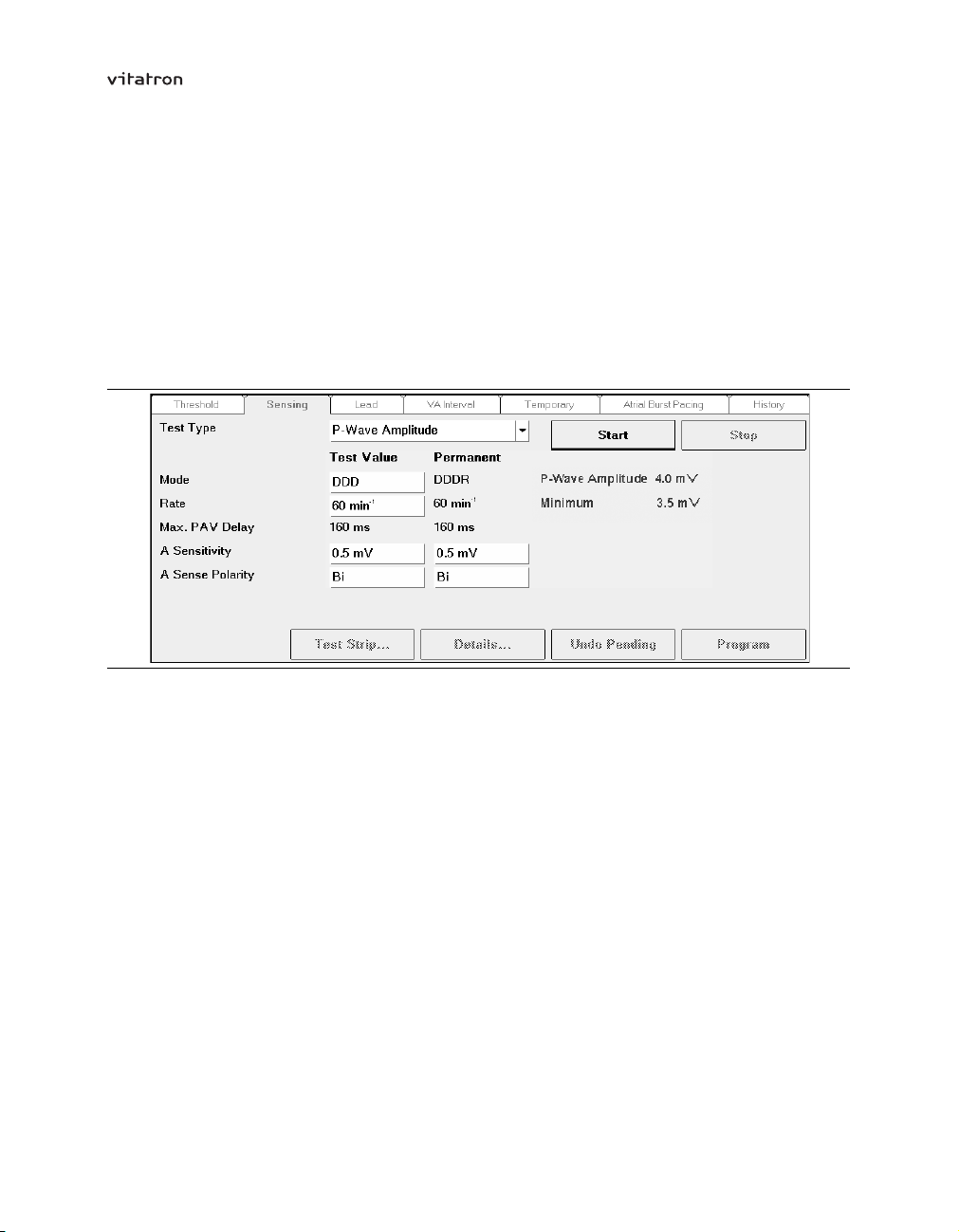
T-series Reference Manual Section 6.3
The P-wave histogram and the P-wave amplitude measurement provide help when
assessing the P-wave sensing safety margin and when programming atrial sensitivity.
First examine the P-wave histogram and look for signs of atrial undersensing, as
described in Section 7.9.1. If atrial undersensing is suspected, measure the P-wave
amplitude.
The P-wave amplitude can be measured even if the permanently programmed pacing
mode does not support atrial sensing.
Figure 35. Sensing window: P-wave Amplitude
Setting up the P-wave amplitude test – To prepare for the test take the following steps:
1. Position the programming head on the pacemaker.
2. Use the “Test Type” drop-down list to select the P-wave amplitude test.
3. Adjust the test value of atrial sensitivity in the “Test Value” column.
4. Adjust the mode or atrial sense polarity in the “Test Value” column. The test modes
available depend on the permanently programmed mode.
5. Select a test rate between 30 min–1and 120 min–1in the “Test Value” column.
Performing the P-wave amplitude test – The following steps describe the general
procedure:
1. Press [Start] to start the measurement. The programmer monitors atrial events
and displays the measured amplitude. When the user stops the measurement
the programmer processes the results collected during the last 15 seconds of the
83
Page 84
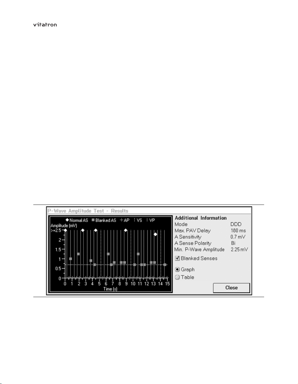
T-series Reference Manual Section 6.3
measurement. The test rate is the only parameter that can be changed during
the test.
2. Watch the EGM or the ECG carefully. The marker annotations (on the programmer
screen) are used to identify sensed atrial events. If no spontaneous atrial events are
sensed, try to decrease the test rate or stop the test and increase the atrial sensitivity.
3. Press [Stop] or remove the programming head to stop the measurement.
4. Press [Test Strip…] to view the ECG recorded during the last measurement.
5. If the measurement was successful, the last measured P-wave amplitude and the
minimum P-wave amplitude are displayed on the right-hand side of the Sensing
window.
6. Press [Details…] to view the detailed results of the test. They are presented either
in a graph (see Figure 36) or in a table. Select the preferred representation by
pressing the “Graph” or “Table” radio button. Press the “Blanked Senses” check box
to mark the atrial senses that would normally be blanked (see Section 9.7 for advice
on adjusting the atrial blanking periods).
7. Press [Print] to print the sensing test report.
8. Press [Close] to leave the Results window.
Figure 36. P-wave Amplitude Test - Results (graph)
84
Page 85

T-series Reference Manual Section 6.3
Notes:
If the “Permanent” column contains boxed parameters, measuring the P-wave
•
amplitude is not possible. Press [Program] or [Undo Pending] first, then start the
measurement.
During the test the programming head must be continuously applied to the
•
pacemaker. The measurement is interrupted if the programming head is removed.
If the measurement is stopped or interrupted, the pacemaker returns to its
•
permanently programmed settings.
During the P-wave amplitude measurement the magnet mode, Flywheel and rate
•
response are temporarily disabled.
Reprogramming atrial sensitivity – In the “Permanent” column, you can reprogram
the atrial sensitivity based on the outcome of the test. Before reprogramming the atrial
sensitivity, check the outcome of the test against the P-wave amplitude distribution in
the P-wave histogram (see Section 7.9.1).
Vitatron recommends using a sensing safety margin of at least 100%, which means
programming the atrial sensitivity to a setting less than 50% of the measured P-wave
amplitude. This means, for example, programming the atrial sensitivity to a setting less
than 0.5 mV if the measured P-wave amplitude is 1.0 mV.
If a high atrial sensitivity is required, the sensing polarity should be programmed to
bipolar. Unipolar sensing in combination with high atrial sensitivities may result in
myopotential or FFRW sensing and cause inappropriate mode switching. Myopotential
sensing can be investigated while exercising the pectoral muscles. Check the marker
channel for sensed atrial events not due to sensed P-waves. The latter could apply to
far-field R-wave senses as well. FFRW sensing can be avoided by programming an
appropriate atrial blanking or by reducing the atrial sensitivity. However, reducing the
atrial sensitivity requires the amplitudes of the far-field R-waves to be much smaller than
those of true atrial signals to avoid atrial undersensing. The P-wave histogram reveals
the amplitude distribution of sensed and blanked atrial events. FFRW sensing can be
confirmed by the VA interval histogram, VA interval measurement or temporary test.
In case of spontaneous AV conduction, check for reliable atrial sensing by reducing the
lower rate and programming a short AV delay.
85
Page 86
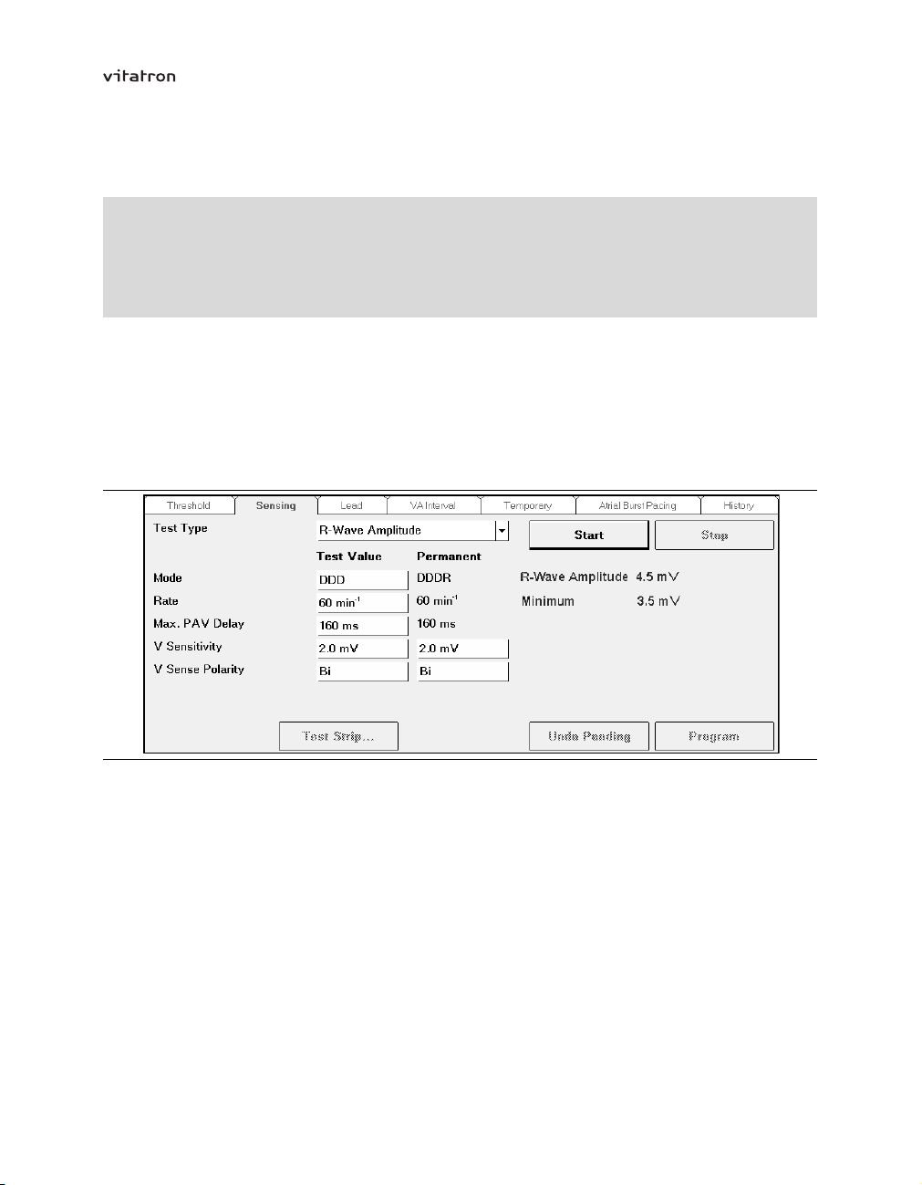
T-series Reference Manual Section 6.3
6.3.4 R-wave sensing
Tests
⇒ Sensing
⇒ R-wave Amplitude
Availability: All modes (except single chamber (A) pacemaker)
This measurement provides help when assessing the R-wave sensing safety margin and
when programming ventricular sensitivity.
The R-wave amplitude can be measured even if the permanently programmed pacing
mode does not support ventricular sensing.
Figure 37. Sensing window: R-wave Amplitude
Setting up the R-wave amplitude test – To prepare for the test take the following steps:
1. Position the programming head on the pacemaker.
2. Use the “Test Type” drop-down list to select the R-wave amplitude test.
3. Adjust the test value of ventricular sensitivity in the “Test Value” column.
4. Adjust the mode and ventricular sense polarity in the “Test Value” column. The
test modes available depend on the permanently programmed mode. Temporarily
programming the pacemaker to the VVI mode may be useful for patients with a
high degree AV block.
86
Page 87

T-series Reference Manual Section 6.3
5. In the “Test Value” column, adjust both the (lower) rate and the maximum paced
AV delay to an appropriate value to prevent ventricular pacing. The test rate is
programmable from 30 min–1to 120 min–1.
Performing the R-wave amplitude test – The following steps describe the general
procedure:
1. Press [Start] to start the measurement. The programmer monitors ventricular events
until the user stops the measurement. The programmer then processes the results
of the 10 last measured R-wave amplitudes. The test rate and the maximum paced
AV delay are the only parameters that can be changed during the test.
2. Watch the EGM or the ECG carefully. The marker annotations (on the programmer
screen) are used to identify sensed ventricular events. If no ventricular events are
sensed, try to lengthen the maximum paced AV delay or to decrease the test rate.
Alternatively, stop the test and increase the ventricular sensitivity.
3. Press [Stop] or remove the programming head to stop the measurement.
4. If no ventricular events are sensed during the measurement, the programmer
screen displays a message.
5. If the measurement was successful, the last measured R-wave amplitude and the
minimum R-wave amplitude are displayed on the right-hand side of the Sensing
window.
6. Press [Test Strip…] to view the ECG recorded during the last measurement.
7. Press [Print] to print the sensing test report.
Notes:
If the “Permanent” column contains boxed parameters, measuring the R-wave
•
amplitude is not possible. Press [Program] or [Undo Pending] first, then start the
measurement.
During the test the programming head must be continuously applied to the
•
pacemaker. The measurement is interrupted if the programming head is removed.
If the measurement is stopped or interrupted, the pacemaker returns to its
•
permanently programmed settings.
During the R-wave amplitude measurement the magnet mode, Flywheel and rate
•
response are temporarily disabled.
Reprogramming ventricular sensitivity – In the “Permanent” column, you can
reprogram the ventricular sensitivity based on the outcome of the test. Vitatron
recommends using a sensing safety margin of at least 100%, which means programming
87
Page 88

T-series Reference Manual Section 6.3
the ventricular sensitivity to a setting less than 50% of the measured R-wave amplitude.
This means, for example, programming the ventricular sensitivity to a setting less than
3.0 mV if the measured R-wave amplitude is 6.0 mV.
Diagnostic information in the Rhythm Overview window can be helpful when assessing
ventricular sensing. Ventricular undersensing could be suspected if the percentage
ventricle paced counter is higher than expected.
Ventricular oversensing should be suspected if the VSPs counter is high (crosstalk)
or if the PVCs counter is higher than expected (myopotential sensing). Programming
the ventricular sensing polarity to bipolar or selecting a less sensitive ventricular
sensitivity setting (which means programming a higher ventricular sensitivity value) is
then recommended. Use the ECG to check that the PVCs counter is not increased by
atrial undersensing (see Section 7.9.1).
6.4 Lead measurement
Tests
⇒ Lead
Availability: All modes, except OOO
The lead measurement is used to measure the exact output voltage, mean output
current, pulse energy and lead impedance for the atrial or ventricular lead, as shown in
Figure 38. In a single chamber mode, only the active chamber is displayed.
The lead measurement is performed automatically every 10 minutes and the most recent
information is read out during initial interrogation of the pacemaker. The results are
stored for later review or printing. If required, the lead measurement can be repeated in
the Lead window.
88
Page 89
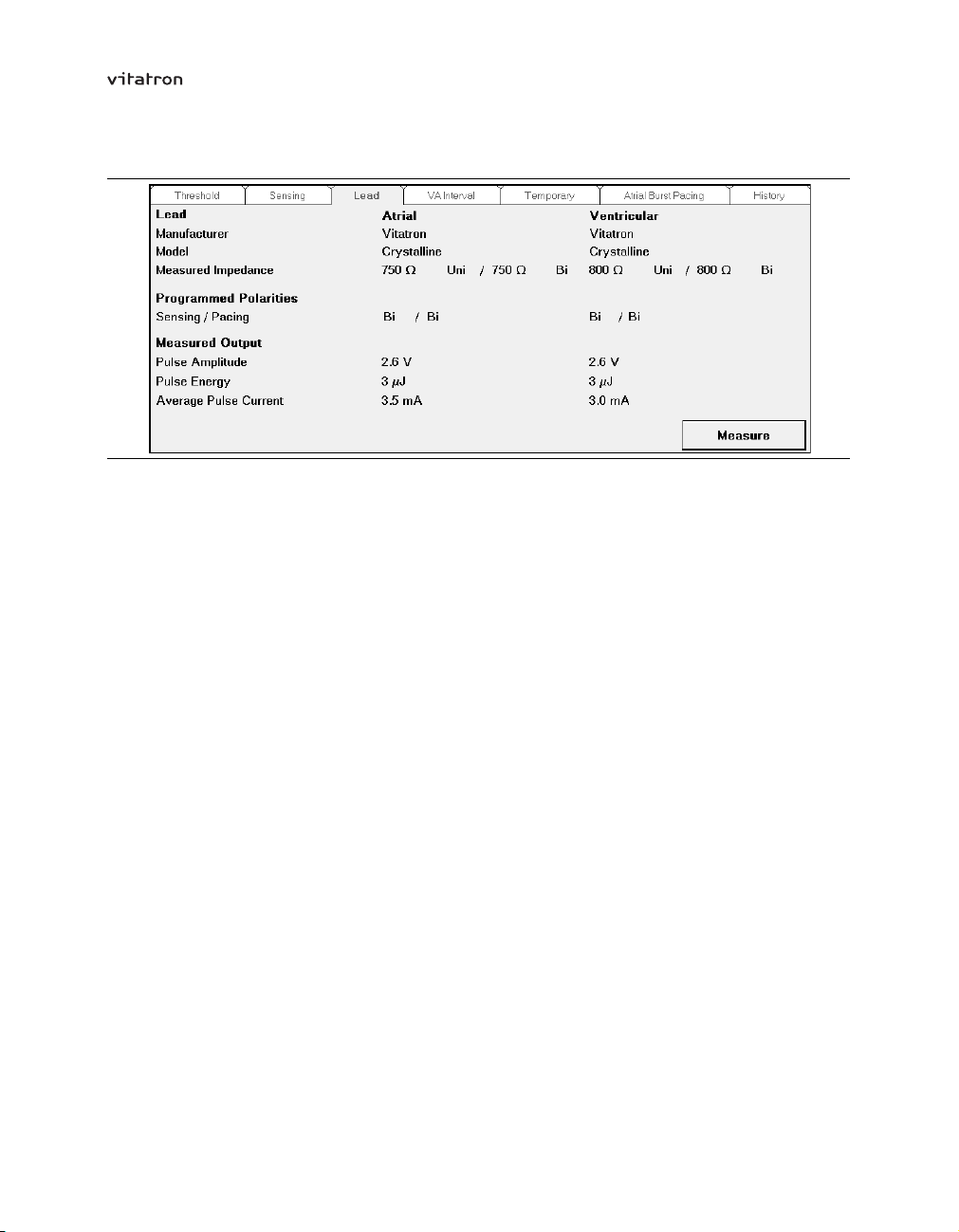
T-series Reference Manual Section 6.4
Figure 38. Lead window (dual chamber pacemaker)
Performing the lead measurement – The following steps describe the general
procedure:
1. Position the programming head on the pacemaker.
2. Press [Measure] to start the measurement. The measurement ends automatically.
3. If the measurement was successful, the programmer displays the measured lead
impedance, pulse amplitude, pulse energy and average pulse current for the atrial or
ventricular lead. Press [Print] to print the battery status/lead measurement report.
4. If the measurement was not successful, the programmer displays a message
indicating why the lead measurement failed.
Notes:
During the test the programming head must be continuously applied to the
•
pacemaker. The measurement is ended if the programming head is removed.
If the pacing or sensing polarity is bipolar, both the unipolar and bipolar lead
•
impedance are measured.
Lead impedance measurement results may be disturbed by electrocardiogram
•
monitoring equipment.
Interpretation of the lead measurement results – The lead measurement provides
information about the safety margin between the measured stimulation threshold and
the actual output voltage. It also gives information about the actual power consumption
of the pacemaker. The trend in lead impedance is an indication for the stability of the
lead. A significant decrease in impedance may indicate an insulation problem or a short
89
Page 90

T-series Reference Manual Section 6.5
circuit, while a significant increase may indicate a lead fracture, loose setscrew or a
possible electrode dislocation.
6.5 VA interval measurement
Tests
⇒ VA Interval
Availability: DDD(R), DDI(R), VDD(R) modes
Dual chamber pacemakers feature a VA interval measurement, manual and automatic,
which is helpful in diagnosing retrograde conduction and FFRW sensing. During this test
the interval between the paced ventricular event and the sensed atrial event is measured
at one (manual test) or three (automatic test) ventricular pacing rates. The manual test
should be repeated at different rates to avoid a false positive diagnosis of retrograde
conduction if the sinus rhythm is the same as the ventricular pacing rate.
Warning: During the VA interval measurement the mode is changed to a ventricular
pacing mode. Consequently, there is no response to atrial arrhythmias.
6.5.1 Manual VA interval measurement
Figure 39. VA Interval window (manual test)
Setting up the manual VA interval measurement – To prepare for the measurement
take the following steps:
90
Page 91

T-series Reference Manual Section 6.5
1. Position the programming head on the pacemaker.
2. Use the “Test Type” drop-down list to select the manual test.
3. Select the test rate in the “Test Value” column. The test rate can be any value from
40 min–1to 130 min–1.
4. Adjust the atrial sensitivity, atrial sense polarity and atrial blanking in the “Test Value”
column.
Performing the manual VA interval measurement – The following steps describe
the general procedure:
1. Press [Start] to start the measurement. The programmer measures the VA interval
until the measurement is stopped.
2. Watch the EGM or ECG carefully on the programmer display. The marker
annotations are useful to identify the atrial and ventricular events. The measured
VA intervals are shown as marker intervals in the ECG window. If the pacemaker is
inhibited by spontaneous ventricular activity, stop the measurement and increase
the test rate. The test rate can be changed during the measurement if the VA
interval has already been measured at the new rate.
3. Press [Stop] or remove the programming head to stop the measurement.
4. Press [Test Strip…] to view the ECG recorded during the last measurement.
5. Press [Details…] to view the results of the measurement. They are presented
either in a graph (see Figure 41) or in a table. Select the preferred representation
by pressing the “Graph” or “Table” radio button. For the manual test, the last six
measurement rates are displayed.
6. Press [Print] to print the VA interval measurement report.
7. Press [Close] to leave the Results window.
91
Page 92

T-series Reference Manual Section 6.5
Notes:
If the “Permanent” column contains boxed parameters, measuring the VA intervals is
•
not possible. Press [Program] or [Undo Pending] first, then start the measurement.
During the test the programming head must be continuously applied to the
•
pacemaker. The measurement is interrupted if the programming head is removed.
When the measurement is stopped or interrupted, the pacemaker returns to its
•
permanently programmed settings.
The VA interval is measured in the VVI mode. During the measurement Flywheel
•
and rate response are temporarily disabled.
Measured VA intervals are stored in the programmer memory. They can be printed
•
later by selecting the “VA Interval Measurement” report in the Reports window.
6.5.2 Automatic VA interval measurement
Figure 40. VA Interval window (automatic test)
Setting up the automatic VA interval measurement – To prepare for the measurement
take the following steps:
1. Position the programming head on the pacemaker.
2. Use the “Test Type” drop-down list to select the automatic test.
3. Select the maximum test rate in the “Test Value” column. The maximum test rate
can be any value from 40 min
4. Adjust the atrial sensitivity, atrial sense polarity and atrial blanking in the “Test Value”
column.
–1
above the programmed lower rate up to 130 min–1.
92
Page 93

T-series Reference Manual Section 6.5
Performing the automatic VA interval measurement – The following steps describe
the general procedure:
1. Press [Start] to start the measurement. The programmer automatically starts to
measure the VA interval at a rate 20 min–1above the programmed lower rate. The
start rate is increased by 10 min–1if there are more than three sensed ventricular
events in the first ten pacing cycles. The check for sensed ventricular events and the
increase of the start rate is repeated until fewer than four sensed ventricular events
occur in the first ten pacing cycles. The current rate is then used as the start rate. If
the start rate exceeds the selected maximum test rate, the test is stopped and a
warning is displayed on the programmer screen.
2. The pacemaker automatically repeats the test at a rate 10 min–1above the start rate
and at a rate 20 min–1above the start rate.
3. If the test rate of the third measurement exceeds the selected maximum test rate, the
measurement is stopped and a message is displayed on the programmer screen.
4. The measurement ends automatically after the third measurement. The pacemaker
returns to its permanently programmed settings.
5. Press [Test Strip…] to view the ECG recorded during the last measurement.
6. Press [Details…] to view the results of the measurement. They are presented either
in a graph (see Figure 41) or in a table. Select the preferred representation by
pressing the “Graph” or “Table” radio button.
7. Press [Print] to print the VA interval measurement report.
8. Press [Close] to leave the Results window.
Figure 41. VA Interval Measurement - Results (graph)
93
Page 94

T-series Reference Manual Section 6.5
Notes:
If the “Permanent” column contains boxed parameters, measuring the VA intervals is
•
not possible. Press [Program] or [Undo Pending] first, then start the measurement.
During the test the programming head must be continuously applied to the
•
pacemaker. The measurement is interrupted if the programming head is removed.
When the measurement is completed or interrupted, the pacemaker returns to
•
its permanently programmed settings.
The VA interval is measured in the VVI mode. During the measurement Flywheel
•
and rate response are temporarily disabled.
Measured VA intervals are stored in the programmer memory. They can be printed
•
later by selecting the “VA Interval Measurement” report in the Reports window.
6.5.3 Programming advice to prevent FFRW sensing and retrograde conduction
Programming advice to prevent FFRW sensing – When the measured VA interval is
shorter than 200 ms FFRW sensing should be suspected. Check the EGM or ECG for
retrograde conduction between 150 and 200 ms. Try to eliminate FFRW sensing by
changing the sensing polarity to bipolar, changing the atrial sensitivity to a less sensitive
(higher) setting or lengthening the atrial blanking period.
Programming advice to prevent retrograde conduction – If the VA interval is stable
between 150 and 450 ms, at different ventricular pacing rates, retrograde conduction
should be suspected. To prevent retrograde conduction and avoid inducing pacemaker
mediated tachycardias (PMTs), Vitatron recommends programming mode switching
to “Auto”, PVC synchronous atrial stimulation to “On” or programming a short atrial
synchronization pace (ASP) interval.
Note: Although the VA interval measurement may reveal retrograde conduction in the
test mode (VVI), a permanently programmed AV synchronous mode might prevent the
occurrence of retrograde conduction (see Section 11.6).
94
Page 95

T-series Reference Manual Section 6.6
6.6 Temporary test
Tests
⇒ Temporary
Availability: All modes
Temporary test offers the possibility to temporarily reprogram a number of basic pacing
parameters for diagnostic purposes or for testing the effects of reprogramming on pacing.
The permanently programmed settings are restored automatically when the temporary
test ends or when the programming head is removed.
Figure 42. Temporary window (dual chamber pacemaker)
Figure 43. Temporary window (single chamber pacemaker)
95
Page 96

T-series Reference Manual Section 6.6
Setting up the temporary test – To prepare for the test take the following steps:
1. Position the programming head on the pacemaker.
2. Adjust the test values for mode, rate, maximum paced AV delay, atrial blanking (on
VP and VS), amplitude (atrial and ventricular), pulse duration (atrial and ventricular)
and sensitivity (atrial and ventricular) in the Temporary Test window.
3. Select the appropriate test mode using the following guidelines:
Use the OOO mode to check the patient’s intrinsic rhythm.
•
Use the AAI mode to check AV conduction at various rates.
•
Use the VVI mode to test for pacemaker syndrome (retrograde conduction).
•
Use the triggered modes (AAT and VVT) to check sensing characteristics.
•
4. Increase or decrease the test rate to respectively suppress or search for intrinsic
rhythm
5. Adjust pulse amplitude or pulse duration to investigate crosstalk at high output
settings (in combination with a low sensitivity setting in the other channel).
6. Adjust the temporary sensitivity values to check for myopotentials (in combination,
for example, with a triggered mode) or for crosstalk (in combination with high output
settings in the other channel).
7. In dual chamber pacemakers, temporarily change the atrial blanking period to check
for the occurrence of far-field R-waves (in combination with low atrial sensitivity
settings).
8. In dual chamber pacemakers, temporarily change the maximum paced or sensed AV
delay to search for intrinsic AV conduction, to optimize AV delay or to prevent fusion.
Performing the temporary test – The following steps describe the general procedure:
1. Press [Start] to start the test.
2. Watch the ECG carefully on the programmer display. During the test all parameters,
except mode, can be changed.
3. Press [Stop] or remove the programming head to stop the test. The pacemaker
returns to its permanently programmed settings.
4. Press [Test Strip…] to view the ECG recorded during the last temporary test.
Note: During the test the programming head must be continuously applied to the
pacemaker. The measurement is interrupted if the programming head is removed.
96
Page 97

T-series Reference Manual Section 6.7
6.7 Atrial burst pacing
Tests
⇒ Atrial Burst Pacing
⇒ A Burst Rate
Range: 100 - (10) - 320 - (15) - 425 min
Availability: All modes, except OOO
Tests
⇒ Atrial Burst Pacing
⇒ VOO Backup
Range: On, Off
Availability: All modes, except OOO
Atrial burst pacing can be used in an attempt to end an atrial tachyarrhythmia (for
example atrial flutter). By programming the atrial burst rate above the spontaneous atrial
rate, it may be possible to end the atrial tachyarrhythmia.
–1
During this procedure VOO backup pacing can be enabled. VOO backup pacing is useful
for patients with a high degree AV block, because their intrinsic ventricular rate might
be too low. When VOO backup pacing is programmed on, the ventricle is paced at the
ventricular backup rate. The ventricular backup rate is not programmable; it depends on
the selected atrial burst rate and varies between 60 min–1and 110 min–1.
Atrial burst pacing can also be used to determine the Wenckebach point of the heart in
patients with intact AV conduction. The Wenckebach point is determined by increasing
the atrial burst rate and observing the spontaneous AV conduction to the ventricles.
97
Page 98

T-series Reference Manual Section 6.7
Figure 44. Atrial Burst Pacing window
Setting up the atrial burst pacing test – To prepare for the test take the following steps:
1. Position the programming head on the pacemaker.
2. Program the atrial burst rate by pressing on the parameter value box or by pressing
the increase or decrease buttons. The atrial burst rate displayed is either the last
programmed value or the delivery setting. (The delivery setting is displayed at the
first test or after a partial restore.)
3. If required, program VOO backup pacing to “On”. When VOO backup pacing is
programmed on, the ventricular backup rate is displayed.
Performing the atrial burst pacing test – The following steps describe the general
procedure:
1. Press [Start] to start the test.
2. Watch the EGM or the ECG carefully. The marker annotations (on the programmer
screen) are useful to identify the atrial or ventricular events. During the test the atrial
burst rate can be changed, provided VOO backup pacing is off. VOO backup pacing
cannot be programmed on once the test is started.
3. Press [Stop] or remove the programming head to stop the test.
4. Press [Test Strip…] to view the ECG recorded during the last test.
98
Page 99

T-series Reference Manual Section 6.7
Notes:
During the test the programming head must be continuously applied to the
•
pacemaker. The test is interrupted if the programming head is removed.
When the test is completed or interrupted, the pacemaker returns to its permanently
•
programmed settings. The last programmed atrial burst rate is stored in the
pacemaker and is used as the starting rate if atrial burst pacing is selected again.
During atrial burst pacing the atrial pulse amplitude, the atrial pulse duration and the
•
atrial pace polarity are the permanently programmed values.
Atrial burst pacing is not possible if the atrial or ventricular pulse amplitudes are
•
programmed above 3.75 V or if the battery status is “Ageing” or “Replace PM”.
6.8 Tests history
Tests
⇒ History
Tests history shows the results of automatic lead impedance measurements, threshold
tests and sensing from the current follow-up session and up to five previous collection
periods.
On the cardiac dashboard, you can press a hyperlink to see a graphical presentation of
the history of that measurement over the previous follow-up periods (see Section 4.3).
Threshold – Threshold measurements that are obtained during the follow-up session are
stored in history. Changes in threshold measurement over time may indicate an unstable
lead position, ischemia, or the effects of (changes in) drug therapy.
Lead impedance – The lead impedance is the last value measured at initial interrogation.
Results of manually initiated lead impedance measurements are not stored in History.
P-wave amplitude – The P-wave amplitude is an average value derived from the P-wave
amplitude histogram at initial interrogation. P-wave amplitude measurements that are
obtained during the follow-up session are not stored in history.
R-wave amplitude – R-wave amplitude measurements that are obtained during the
follow-up session are stored in history.
99
Page 100

T-series Reference Manual Section 6.8
Notes:
Pressing [Clear History] clears all the diagnostics and tests history data in the
•
pacemaker. Only the data from the current follow-up session remains in the
pacemaker.
100
 Loading...