


M708348B166E Rev A
Anchor FS™ Facet Fixation System
ENGLISH
Anchor FS™ Facet Fixation System
INDICATIONS FOR USE
The Anchor FS™ Facet Fixation System is intended to stabilize the spine as an aid to fusion by
lumbar bilateral facet fixation, with or without bone graft.
This system is indicated for posterior surgical treatment of any or all of the following at L1 to S1
(inclusive) spinal levels, at single or multiple levels:
Trauma, including spinal fractures and/or dislocations
Spondylolisthesis
Spondylolysis
Pseudoarthrosis or failed previous fusions which are symptomatic or which may cause
secondary instability or deformity
Degenerative diseases which include degenerative disc disease (DDD) as defined by back
pain of discogenic origin as confirmed by patient history with degeneration of the disc as
confirmed by radiographic studies and/or degenerative disease of the facets with instability.
2012-08
Medtronic Sofamor Danek USA, Inc.
1800 Pyramid Place
Memphis, TN 38132, USA
Telephone 800 933 2635 (In U.S.A.)
901 396 3133 (Outside U.S.A.)
Fax 901 396 0356
INSTRUCTIONS FOR USE
DEVICE DESCRIPTION
The Anchor FS™ Facet Fixation System is designed to provide bilateral, transfacet-pedicular
fixation of the spinal facet joint in the lumbar spine.
The Anchor FS™ Facet Screws are cannulated, and partially threaded, 4.5mm diameter screws
offered in lengths of 25-40mm (in 5mm increments). The device is composed of medical grade
Titanium. The devices are offered with a nut and a washer. The washer seats against the nut
and distributes the load placed by the nut onto the inferior articular process. The washer is
held in place during shipment with a plastic disposable retaining clip, which is removed prior to
implant of the screw, nut, and washer.
pg. 1 of 13
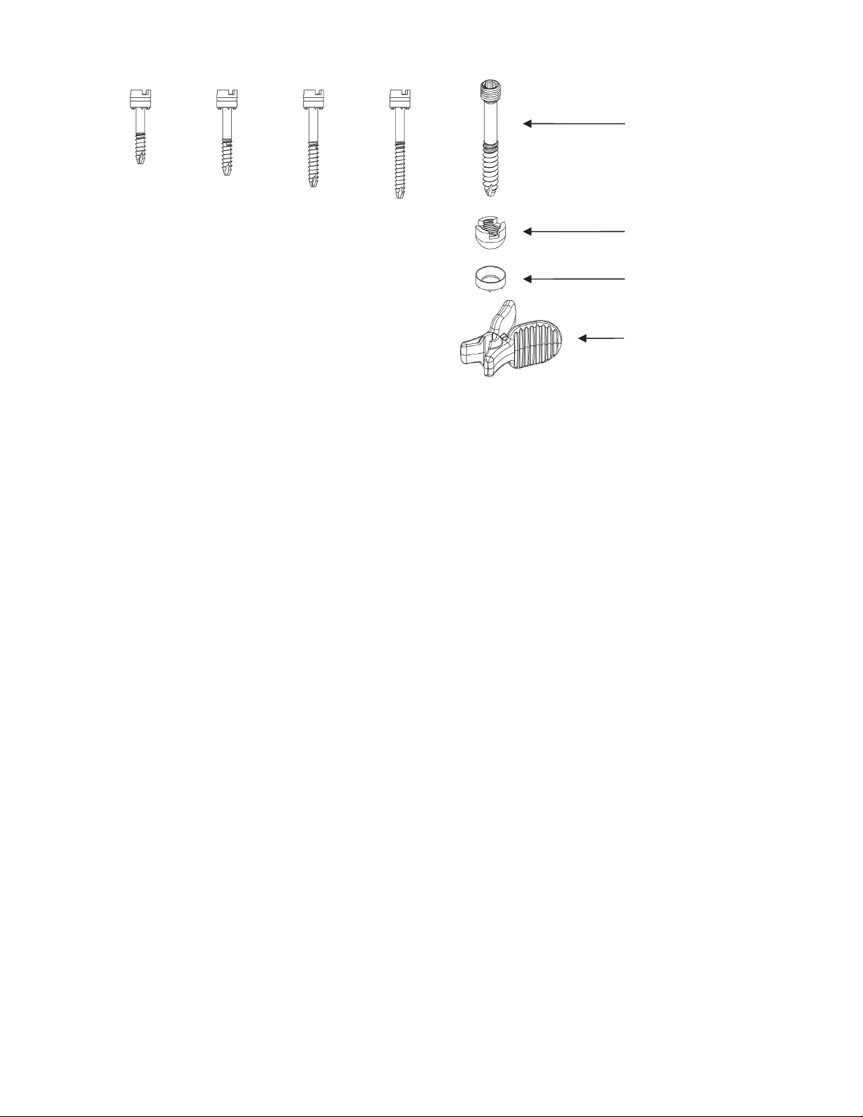
Screw
25 mm 30 mm 35 mm 40 mm
Nut
Washer
Retaining Clip
CONTRAINDICATIONS
The contraindications include, but are not limited to:
Active infectious process or significant risk of infection (immunocompromise)
Signs of local inflammation
Fever or leukocytosis
Morbid obesity
Pregnancy
Mental illness
Grossly distorted anatomy due to congenital, developmental, traumatic, previous surgery, or
severe degenerative conditions limiting anatomical definition to allow safe screw insertion
Bone disease from osteoporosis, osteopenia, or bone resorption is a relative contraindication
since this condition limits the degree of correction and the quality of the mechanical fixation.
Any patient lacking adequate soft tissue coverage over the operative site
Any medical or surgical condition which would preclude the potential benefit of spinal implant
surgery, such as the presence of tumors or congenital abnormalities, elevation of
sedimentation rate unexplained by other diseases, elevation of white blood count (WBC), or
a marked left shift in the WBC differential count
Suspected or documented metal allergy or intolerance
Any case where metals must be mixed from different components
Any case where the implant components selected for use would be too large or too small to
achieve a successful result
Any case where a bone graft and fusion is unnecessary or where fracture healing is not
required
Any patient in which implant utilization would interfere with anatomical structures or expected
physiological performance
Any patient unwilling to follow the post-operative instructions
Any case not described in the indications
CAUTION: Federal law (USA) restricts this device to sale by or on the order of a physician.
WARNINGS
pg. 2 of 13

While the screw has been determined to be MR conditional, metallic instruments have not.
As such, metallic instruments are considered MR unsafe, and should not be brought into the
MR environment.
Avoid contact of the implants of this system with other metallic and non-metallic implants to
prevent corrosion, wear, and other adverse effects
Proper patient selection is extremely important to the eventual success of the procedure
Correct selection of the implant is extremely important. Take into account the size and shape
of human bones when selecting the implant size. Metallic internal fixation devices cannot
withstand the activity levels and/or loads equal to those placed on normal, healthy bone.
These devices are not designed to withstand the unsupported stress of full weight or loadbearing. A higher risk of devices loosening, bending, or breaking exists with fractures
involving severe comminution, displacement, or other difficult fracture management
situations.
These devices can break when subjected to the increased loading associated with delayed
union or nonunion. Internal fixation appliances are loaded sharing devices, which hold a
fracture in alignment until healing occurs. If healing is delayed, or does not occur, the implant
may eventually loosen, bend, or break.
Loads on the devices produced by load bearing, and the patient’s activity level will dictate
the longevity of the implant.
The implants may be removed after successful fusion has occurred. The surgeon should
weigh the risk versus benefit of explanation prior to implant removal through a second
surgery.
Surgical implants must never be reused. An explanted metal implant should never be re-
implanted. Even though the device may appear undamaged, it may have small defects and
internal stress patterns which may lead to early breakage.
PRECAUTIONS
The Anchor FS
tissues. Do not reuse, reprocess, or resterilize. Reusing this device carries the risk of
contamination and may cause patient infection or cross-infection, regardless of the cleaning
and resterilization methods. There is also an increased risk of the deterioration of the device
performance due to the reprocessing steps, which may lead to patient injury or death.
Do not use this product if you have not been properly trained in its use. Physicians using the
Anchor FS
the selected anatomy, and be trained in the performance of the chosen technique.
It is important to read and understand the Instructions for Use prior to use
Do not use if package is opened or damaged because product integrity, including sterility,
may be compromised
Do not use damaged products. Prior to use, inspect the packaging and product to verify that
no damage has occurred
Use the Anchor FS
The Anchor FS
guidance with radiographic equipment that provides high quality images
If the internal fixation is not completely rigid, it is recommended the patient wear an external
splint or brace, until medical imaging confirms successful fusion of the spine level. The
patient should also be advised to reduce the stress applied to the treated region by limiting
physical activities during this period.
Handle and dispose of this product in accordance with accepted medical practice and
applicable laws and regulations.
™
Facet Fixation System is a single use device intended to contact body
™
Facet Fixation System should be familiar with the physiology and pathology of
™
Facet Fixation System prior to the Use By date noted on the package
™
Facet Fixation System should be placed only while using fluoroscopic
pg. 3 of 13

Reconditioning, refurbishing, repair, modification, or resterilization of the product to enable
further use is expressly prohibited
Based on fatigue testing results, when using this device, the physician/surgeon should
consider the levels of implantation, patient weight, patient activity level, other patient
conditions, etc., which may impact the performance of this system.
PREOPERATIVE
Only patients that meet the criteria described in the indications should be selected.
Patient conditions and/or predispositions such as those addressed in the aforementioned
contraindications should be avoided.
Care should be used in the handling and storage of the implant components. The implants
should not be scratched or otherwise damaged. Implants should be protected during
storage, especially from corrosive environments.
An adequate inventory of implants should be available at the time of surgery, normally a
quantity in excess of what is expected to be used.
Since mechanical parts are involved, the surgeon should be familiar with various
components before using the equipment to verify that all parts and necessary instruments
are present before the surgery begins. The Anchor FS™ Facet Fixation System components
(described in the DESCRIPTION section) are not to be combined with the components from
another manufacturer. Different metal types should never be used together.
INTRAOPERATIVE
Extreme caution should be used around the spinal cord and nerve roots. Damage to the
nerves can cause loss of neurological functions.
Breakage, slippage, or misuse of instruments or implant components may cause injury to the
patient or operative personnel.
To insert a screw properly, a guidewire should first be used. Caution: Be careful that the
guidewire, if used, is not inserted too deep, becomes bent, and/or breaks. Ensure that the
guidewire does not advance during pilot hole drilling or screw insertion. Do not use a screw
that is either too long or too large. Using an incorrectly sized screw may cause nerve
damage, hemorrhage, or the other possible adverse events listed elsewhere in this
Instruction for Use.
POSTOPERATIVE
The physician’s postoperative directions and warnings to the patient, and the corresponding
patient compliance are extremely important.
Detailed instructions on the use and limitations of the device should be given to the patient. If
partial weight-bearing is recommended or required prior to bony fusion, the patient must be
warned that bending, loosening and/or breakage of the device(s) are complications which
may occur as a result of excessive or early weight-bearing or muscular activity. The risks of
bending, loosening, or breakage of temporary internal fixation devices during postoperative
rehabilitation may be increased if the patient is active, or if the patient is debilitated or
demented. The patient should be warned to avoid falls or sudden jolts in spinal position.
To allow the maximum chances for a successful surgical result, the patient or devices should
not be exposed to mechanical vibrations or shock that may loosen the device construct. The
patient should be warned of this possibility and instructed to limit and restrict physical
activities, especially lifting and twisting motions and any type of sport participation. The
patient should be advised not to smoke tobacco or utilize nicotine products, or to consume
pg. 4 of 13

alcohol or non-steroidal or anti-inflammatory medications such as aspirin during the bone
healing process.
The patient should be advised of their inability to bend or rotate at the point of spinal fusion
and taught to compensate for this permanent physical restriction in the body motion.
Failure to immobilize a delayed or non-union of bone will result in excessive and repeated
stress on the implant. By the mechanism of fatigue, these stresses can cause the eventual
bending, loosening, or breakage of the device(s). It is important that immobilization of the
spinal surgical site be maintained until bony union is established and confirmed by
examination. If a state of non-union persists or if the components loosen, bend, and/or
break, the device(s) should be revised and/or removed immediately before serious injury
occurs. The patient must be adequately warned of these hazards and closely supervised to
ensure cooperation until bony union is confirmed.
Any retrieved devices should be treated in such a manner that reuse in another surgical
procedure is not possible. As with all orthopedic implants, the Anchor FS™ Facet Fixation
System components should never be reused under any circumstances.
POSSIBLE ADVERSE EVENTS
All of the possible adverse events associated with spinal fusion surgery without implants are
possible. With implants, a listing of possible adverse events includes, but is not limited to:
Early or late loosening of any or all of the components.
Disassembly, bending, and/or breakage of any or all of the components.
Foreign body (allergic) reaction to implants, debris, and/or corrosion products, including
metallosis, staining, tumor formation, and/or autoimmune disease.
Pressure on the skin from component parts in patients with inadequate tissue coverage over
the implant possibly causing skin penetration, irritation, and/or pain.
Bursitis. Tissue damage caused by improper positioning and placement of implants or
instruments.
Post-operative change in spinal curvature, loss of correction, height, and/ or reduction.
Infection.
Dural tears.
Loss of neurological function, including paralysis (complete or incomplete), dysesthesias,
hyperesthesia, anesthesia, paraesthesia, appearance of radiculopathy, and/or the
development or continuation of pain, numbness, neuroma, or tingling sensation.
Cauda equina syndrome, neuropathy, neurological deficits (transient or permanent), bilateral
paraplegia, reflex deficits, and/or arachnoiditis.
Urinary retention or loss of bladder control or other types of urological system compromise.
Scar formation possibly causing neurological compromise around nerves and/or pain.
Fracture, microfracture, resorption, damage, or penetration of any spinal bone (including the
sacrum, pedicles, spinous process, and/or vertebral body) and/or bone graft or bone graft
harvest site at, above, and/or below the level of surgery.
Non-union (or pseudarthrosis). Delayed union. Mal-union.
Cessation of any potential growth of the operated portion of the spine. Loss of spinal mobility
or function.
Inability to perform activities of daily living.
Bone loss or decreases in bone density, possibly caused by stress shielding.
Herniated nucleus pulposus, disc disruption, or degeneration at, above, or below the level of
surgery.
pg. 5 of 13

Hemorrhage, hematoma, occlusion, seroma, edema, hypertension, embolism, stroke,
excessive bleeding, phlebitis, wound necrosis, wound dehiscence, damage to blood vessels,
or other types of cardiovascular system compromise.
Reproductive system compromise, including sterility, loss of consortium, and sexual
dysfunction.
Development of respiratory problems, e.g. pulmonary embolism, atelectasis, bronchitis,
pneumonia, etc.
Change in mental status.
Death.
NOTE: Additional surgery many be necessary to correct some of these adverse events.
DIRECTIONS FOR USE
Recommended Materials
Small orthopedic power drill with a guidewire attachment and Jacob’s chuck. Refer to the
manufacturer instructions for proper use of power drill.
11 gauge needle
guidewire
access cannula
3.0mm drill bit
3.5mm Hex head driver
Note: An 11gauge needle, guidewire, access cannula (with stylet), 3.0mm drill bit, and 3.5mm
Hex head driver are all provided in the Medtronic Facet Screw Instruments Kit.
Note: The Anchor FS™ Facet Screw is to be implanted following placement of fusion devices.
Note: Before each step of the facet screw system placement, check fluoroscopic imaging to
ensure appropriate position of the devices.
1. Using fluoroscopy, introduce the 11 Gauge Needle through the skin. Appropriate trajectory
to place a facet screw in a transfacet-pedicular approach is determined by using the 11
Gauge Needle and fluoroscopy based on patient anatomy. An 11 gauge needle is included
in the Medtronic Facet Screw Instruments.
pg. 6 of 13

Figure 1: Medtronic 11 Gauge Needle Placement
Note: If using an open approach, prior to introducing the 11 gauge needle, expose the
spinous process of the cephalad vertebrae and the pars interarticularis of the caudal
vertebrae. It is not necessary to dissect lateral to the superior articular process of the facet
joint.
2. Once the 11 gauge needle is properly aligned, remove the stylet. Insert a guidewire
through the needle. Using a power drill and fluoroscopy, drive the guidewire across the
facet joint and into the pedicle until the tip appears to reach the posterior aspect of the
vertebral body. Once the guidewire is properly positioned and access to the desired level
is obtained, remove the 11 gauge needle, taking care to ensure the guidewire remains in
position. A guidewire is included in the Medtronic Facet Screw Instruments.
Figure 2: Medtronic Guidewire Placement
Note: Once the Guidewire is appropriately positioned, ensure that it remains in position
throughout all steps of the procedure.
3. a) Once a skin incision is made, insert an access cannula, minimum inner diameter of 9.0
mm, over the guidewire, and advance the access cannula through the tissue until the distal
end makes contact with the guidewire entry point on the inferior articular process. An
access cannula is included in the Medtronic Facet Screw Instruments.
b) The access cannula and guidewire included in the Medtronic Facet Screw Instruments
provides an option to note the depth reading of the guidewire on the stylet. The alignment
between the distal end of the black marker on the guidewire and the numbering on the
stylet handle indicates the depth of the guidewire relative to the inferior articular process
entry point.
pg. 7 of 13

Figure 3: Medtronic Access Cannula Placement & Depth Measurement
Note: Fluoroscopy should be used in conjunction with a guidewire to determine a depth
measurement, and selection of the appropriate facet screw size.
c) If using the Medtronic Facet Screw Instruments, remove the stylet from the cannula. The
stylet is removed from the access cannula provided in the Medtronic Facet Screw
Instruments by rotating the stylet counter-clockwise and removing the stylet from the
cannula. Advance the cannula anteriorly until it makes contact with the inferior articular
process.
4. a) Attach a 3.0mm drill bit to a power drill. A drill bit is included in the Medtronic Facet
Screw Instruments. The drill bit included in the Medtronic Facet Screw Instruments comes
with a drill clip that can be used to provide a hard stop when drilling when the drill clip
contacts the cannula. The guidewire depth measurement noted in Step 3b can be used to
determine where to attach the drill clip to the drill bit.
Figure 4: Medtronic Drill Bit Assembly
b) Insert the drill bit, attached to the power drill, over the guidewire and into the cannula.
Drill across the facet joint and into the pedicle until the drill bit has reached the posterior
wall of the vertebral body. Confirm appropriate drill position via fluoroscopy.
pg. 8 of 13

Figure 5: Medtronic Drill Placement
c) To remove the drill bit, reverse the direction of the drill, and slowly guide the drill bit out,
while maintaining guidewire placement.
Note: Maintain the guidewire in place while pulling the drill out to maintain correct trajectory
of subsequent tools. It is recommended to detach the drill from the drill bit during removal.
5. a) Attach the appropriate size facet screw (consider the guidewire depth measurement
noted in Step 3b) to a 3.5mm Hex head driver. A 3.5mm Hex head driver is included in the
Medtronic Facet Screw Instruments and can be attached to the facet screw by pulling back
on the knurled knob. Firmly insert the tip of the inner shaft of the driver into the facet screw.
While holding the facet screw, gradually release the driver knob and align the castles on
the driver with the nut.
Figure 6: Medtronic Driver and Screw Attachment
b) Place the facet screw attached to the driver over the guidewire and into the cannula.
Detach the orange Retaining Clip from the screw once the screw is completely on the
guidewire.
pg. 9 of 13

Figure 7: Medtronic Retaining Clip Removal
c) Advance the facet screw across the facet joint and into the pedicle until the distal end of
the black marker band on the driver is in line with the top surface of the cannula hub. This
alignment indicates the facet screw has been fully inserted and the washer has exited the
distal end of the cannula.
d) Using fluoroscopy, verify screw placement and that the washer has made contact with
the inferior articular process.
Figure 8: Medtronic Screw Placement
Note: If desired, the guidewire may be removed once you have begun advancing the facet
screw across the joint.
6. Detach the driver from the facet screw by pulling the driver proximally out of the cannula.
Remove the cannula and guidewire, if not previously removed.
Repeat all steps on the contralateral side.
pg. 10 of 13

REVISION/REMOVAL INSTRUCTIONS
1. Using a 3.5mm hex driver or the screw driver included in the Medtronic Facet Screw
Instruments, rotate the facet screw counterclockwise until the facet screw is removed from
the articular processes.
2. Use forceps to remove the washer.
STERILIZATION
Sterilized with irradiation.
HOW SUPPLIED
The Anchor FS™ Facet Fixation System is supplied sterile in a peel-open package. In the
event of damage to the sterile packaging, do not use and notify the manufacturer.
STORAGE
Proper care should be taken to ensure that the instruments will not be damaged. Store in a
cool dry place.
LIMITATION OF LIABILITY
MEDTRONIC WILL NOT BE RESPONSIBLE FOR ANY DIRECT, INDIRECT, INCIDENTAL,
CONSEQUENTIAL, OR EXEMPLARY DAMAGES RESULTING FROM REUSE OF THE
ANCHOR FS™ FACET FIXATION SYSTEM.
IN NO EVENT SHALL MEDTRONIC BE LIABLE FOR ANY DIRECT, INDIRECT,
INCIDENTAL, CONSEQUENTIAL, OR EXEMPLARY DAMAGES ARISING OUT OF OR IN
CONNECTION WITH THE ANCHOR FS™ FACET FIXATION SYSTEM BASED UPON
BREACH OF CONTRACT (INCLUDING BREACH OF WARRANTY).
REQUESTS FOR INFORMATION
For further information, please contact Customer Service, Medtronic Sofamor Danek USA,
Inc., 1800 Pyramid Place, Memphis, Tennessee 38132, Telephone: 800 933 2635 (in U.S.A.),
901 396 3133 (outside U.S.A.), Fax 901 396 0356.
MRI INFORMATION
MR-Conditional
MRI Information. The Anchor FS™ Facet Screw was determined to be MR-conditional
according to the terminology specified in the American Society for Testing and Materials
(ASTM) International, Designation: F2503-05. Standard Practice for Marking Medical Devices
and Other Items for Safety in the Magnetic Resonance Environment. ASTM International, 100
Barr Harbor Drive, PO Box C700, West Conshohocken, Pennsylvania, 2005.
Non-clinical testing demonstrated that the Anchor FS™ Facet Screw is MR Conditional. A
patient with this device can be scanned safely immediately after placement under the following
conditions:
pg. 11 of 13

Static Magnetic Field
-Static magnetic field of 3 Tesla or less
-Maximum spatial gradient magnetic field of 720 Gauss/cm or less
MRI-Related Heating
In non-clinical testing, the Anchor FS™ Facet Screw produced the following temperature rise
during an MRI performed for 15 min in the 3 Tesla (3 Tesla/128 MHz, Excite, HDx, Software
14X.M5, General Electric Healthcare, Milwaukee, WI) MR system:
Highest temperature change +1.9 °C
Therefore, the MRI-related heating experiments for the Anchor FS™ Facet Screw at 3 Tesla
using a transmit/receive RF body coil at an MR system reported whole body averaged SAR of
2.9 W/kg (i.e., associated with a calorimetry measured whole body averaged value of 2.7
W/kg) indicated that the greatest amount of heating that occurred in association with these
specific conditions was equal to or less than +1.9 °C.
Artifact Information
MR image quality may be compromised if the area of interest is in the same area or relatively
close to the position of the Anchor FS™ Facet Screw. The artifact size information is, as
follows:
Pulse sequence T1-SE T1-SE GRE GRE
Signal Void Size 1,439 mm2 633 mm2 2,928 mm2 1,127 mm2
Imaging Plane parallel perpendicular parallel perpendicular
Therefore, optimization of MR imaging parameters to compensate for the presence of this
device may be necessary. The maximum artifact size (i.e., as seen on the gradient echo pulse
sequence) extends approximately 15 mm relative to the size and shape of the Facet Screw (50
mm).
MRI Patient Counseling Information:
Physicians should communicate with the patient the following information about Magnetic
Resonance Imaging (MRI):
Anchor FS™ Facet Screw performance has been established for magnetic resonance
imaging (MRI) scanners at fields of 3.0 Tesla or less.
During an MRI, the patient may notice a warming sensation around the implant or feel a
tingling sensation. If the warming or tingling sensation is uncomfortable, the patient should
communicate this to the MR Technologist, the MRI should be stopped, and the settings
adjusted to reduce or eliminate the sensation. The highest temperature change observed in
non-clinical testing was +1.9 C (associated with specific conditions listed above).
Additionally, the metal in the implant may cause the MRI image to be distorted in the area
around the implant. The MRI can be adjusted to minimize the image distortion.
Physicians should instruct patients to:
Inform any healthcare personnel (e.g., doctor or MR Technologist) that they have an
implanted metallic spinal screw prior to receiving an MRI.
pg. 12 of 13

Information regarding Magnetic Resonance Imaging (MRI) specific to this implant can be
found at www.MRIsafety.com.
The patient’s doctor will recommend whether or not an MRI is appropriate.
©2012 Medtronic Sofamor Danek USA, Inc. All rights reserved.
EXPLANATION OF SYMBOLS
Consult Instructions for Use
Do Not Reuse
Batch Code
Manufacturer
Catalogue Number
Use by
Sterilized using irradiation
Do Not Use If Package Is Damaged
Caution: Federal law (U.S.A.) restricts this
device to sale by or on the order of a physician
For U.S. audiences only
MR Conditional
pg. 13 of 13
 Loading...