

Page 1

ARATHYROID DETECTION SYSTEM
P
MODEL PTEYE
NSTRUCTI ON FOR USE
I
Page 2

Proprietary I nformati on
This manual contains information deemed proprietary to AiBiomed. The information contained herein,
including all of the designs and related materials, is the sole property of AiBiomed and/or its licensors.
AiBiom ed and / o r it s licen s o rs res erv e al l patent, copyright, and other proprietary rights to this document,
including all design, manufacturing methodology, and reproduction.
This document, and any related materials, is confidential and is protected by copyright laws and shall not
be duplicated, transmitted, transcribed, stored in a retrieval system, or translated into any human or
computer l an g u ag e i n any f or m o r by any mean s , el ectronic, mechan i cal , magneti c, m an u al , o r oth erw i s e,
or disclosed to third parties, in whole or in part, without the prior express written consent of AiBiomed.
AiBiomed reserves the right to revise this publication and to make changes from time to time in the
contents hereof without obligation to notify any person of such revision or changes, unless otherwise
required by law.
© Copyright 2015 AiBiomed. All Rights Reserved. Printed in USA.
AiBiomed
114 E Haley St. Suite K
Santa Barbara, CA 93101
www.aibiomed.com
D121254_EN Rev L May 29, 2020
Record the Model and Serial Number of your AiBiomed Model PTeye device in the table bel ow, and
include t h e d at e recei v ed . Retain this in fo rm at ion for future referen ce.
Model Number Ser ial Number Date Received
Page 3

Page 3 of 48
Table of Contents
1 Introduction .......................................................................................................................... 4
1.1 Intended Use ................................................................................................................ 4
1.2 Contraindications ......................................................................................................... 4
1.3 Device Warnin gs an d Precautions ................................................................................ 5
1.3.1 Warnings .............................................................................................. 5
1.3.2 Precautions ....................................................................................................... 7
1.3.3 User Responsibility ........................................................................................... 8
1.3.4 Electrical In t erference [See “Det ai l ed EM C Informati on” s ect ion] .................... 8
1.4 Symbol Definitions ...................................................................................................... 8
1.5 Unpacking the System ............................................................................................... 10
1.5.1 List of Delivered Components ......................................................................... 10
1.5.2 Verifying Probe Assembly Function ............................................................... 10
1.6 Returning the System ................................................................................................. 10
2 System Installation .............................................................................................................. 12
2.1 Connecting Peripherals to the Back ............................................................................ 12
2.2 Connecting Peripherals to the Front of the Console .................................................... 13
3 Pre-Operative S t ep s ............................................................................................................. 15
4 Operating the PTeye ............................................................................................................ 16
4.1 Collecting Baseli n e Thyro i d Data .............................................................................. 16
4.2 Detecting Parathyroid Tissue ..................................................................................... 18
5 Maintenance........................................................................................................................ 20
5.1 Life Expect ancy ......................................................................................................... 20
5.2 Periodi c M ai n t en an ce ................................................................................................ 20
5.3 Cleaning .................................................................................................................... 20
5.3.1 Cleaning the Console, Power Cord, Cable(s) and Footswitch........................... 21
6 Compatible Peripherals ....................................................................................................... 21
7 Troubleshooting .................................................................................................................. 21
8 End of Life Environmental Directives ................................................................................. 23
9 Technical In fo rm at ion ......................................................................................................... 23
9.1 Theory of Operation .................................................................................................. 23
9.1.1 Energy ............................................................................................................ 24
9.1.2 Disease ........................................................................................................... 24
9.2 Technical S p eci f i cat i o n s ............................................................................................ 24
9.2.1 General ........................................................................................................... 24
9.2.2 Laser .............................................................................................................. 25
9.2.3 Dimensions ..................................................................................................... 25
9.2.4 Environmental ................................................................................................ 25
9.2.5 IP Ingress Class .............................................................................................. 25
9.2.6 Safety Tes t i n g ................................................................................................. 26
9.2.7 Power Cord Requirements .............................................................................. 26
10 Software Vers i o n Acces s ..................................................................................................... 26
11 Detailed EMC Information .................................................................................................. 26
12 Summary of Clinical Information ........................................................................................ 31
D121254_EN Rev L PTeye Instructions for Use
Page 4

Page 4 of 48
1 Introduction
The Parathyroid Detection (PTeye) System aids surgeons in confirming suspected parathyroid tissue that
has been located visually by the surgeon during thyroid and parathyroid surgeries using a probe assembly.
The probe assembly includes one quartz (fused si lica) fiber optic element that emits non-ionizing
radiation at 785nm in the near IR range (NIR) and one other fiber opt i c d et ect o r element that coll ect and
transmit the fluorescence emitted by the tissue to a photo detector. Tissue detecti o n is bas ed o n th e ratio
of the fluorescent response of the parathyroid to the thyroid tissue; the fluorescence of thyroid tissue is
much lower than the parathyroid.
During surgery, five data points are collected by touching the probe assembly (Applie d Pa r t) on the
thyroid tissue (or neck muscle/trachea in a patient with no thyroid). The system calcu l at es a b as el i n e
median for t h e thyroid tissue based on those points. The baseline value establishes a reference point for
each patient t o h el p the surgeon confirm parathyroid tissue, which produces a higher level of
fluorescence.
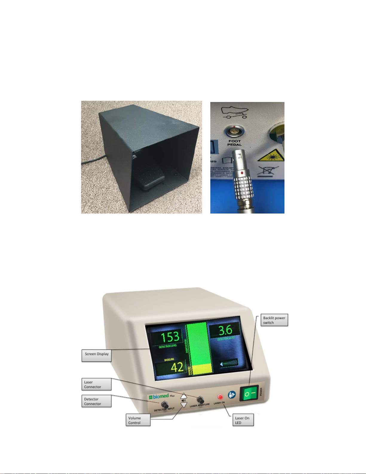
The system consists of the following components:
1. A console that includes:
• A LED display that indicates if the laser is on.
• A display for visual feedback.
• A speaker for auditory feedback.
2. A probe assembly that interfaces into the console unit using two unique connectors. One connector
plugs into the laser output and the other plugs into the phot o detector input (fluorescent signal)
3. A foot pedal attached by a cable to the rear of the unit, used to turn on the laser and initiate d at a
collection
4. An external power supply and power cord that plugs into the power supply
1.1 Intended Use
The AiBi omed P ar at h yr oid Detection Sys tem (Model PTeye) is an adjunctive tool intended to aid in the
identification of parathyroid tissue by confirming parathyroid tissue already visually located by the
surgeon.
1.2 Contraindications
There are no known contraindications for use for the AiBiomed Parathyroid Detection System (Model
PTeye).
D121254_EN Rev L PTeye Instructions for Use
Page 5

Page 5 of 48
1.3 Device Warnings and Precautions
WARNING: The safety and/or health of the patient, user, or a third party is at risk.
PRECAUTION: This contains information concerning the intended use of th e device
This equipment is designed for use by medical professionals familiar with its required techniques and
these instructions for use. Read and follow all warning and cautionary notices and i nstructions included in
this IFU.
The words WARNING, PRECAUTION, and NOTE carry special meanings and they should be
read carefully.
Comply with this warning to avoid injury to the patient, user, or third party.
or accessory. Damage to the equipment is possible if these instructions are not
followed.
NOTE: A note is added to provide additional, focused, information.
1.3.1 Warnings
1. Due to limitations in parathyroid detection of autofluorescence by the PTeye System in certain
disease states, the device is not recommended for use in patients with secondary
hyperparathyroidism and in patients with parathyroid cysts.
2. The PTeye Syst em is intended to be an aid in the identification of parathyroid tissue and not as a
parathyroid locator. The use of this device has not been evaluated as a parathyroid tissue locator.
3. The device is only completely isolated from the mains if the External Power Supply’s power pl ug is
disconnected from the AC Mains.
4. Use of controls or adjustments or performance of procedures other than those specified herein may
result in hazardous radiation exposure.
5. Do not attempt to open or service the console, as this may void your warranty. The console
does not contain any user-serviceable parts inside. Removing the cover may produce an
electric shock hazard by exposing you to dangerous high voltage or other risks. Should the
system malfunction, return it for service immediately.
6. Always connect the probe assembly and the foot pedal before turning on the power switch.
Turn the power off before disconnecting the probe assembly or foot pedal. Never
disconnect the probe assembly or foot pedal while the system is in use. If the unit is on and the
probe assembly is not connected, the laser wil l emit potentially harmful light from the front of the
console, which could harm eyes and skin.
7. Do not use the AiBiomed Model PTeye system if LED power indicator does not light up when the
power switch is in the ON position and the foot pedal is pressed. (See Figu r e 3 in Section 2.2 for
LED power indicator and power switch location).
D121254_EN Rev L PTeye Instructions for Use
Page 6

Page 6 of 48
8. When the unit is on, never point t he tip of the probe assembly at someone else’s face or look at it
directly. Looking at the laser could potentially be harmful to the eyes. If you are unsure if the laser
is on, look at the laser-on LED on the front of the console, not at the probe assembly itself.
9. Never point t h e laser at eyes, skin or point away from the surgical site. The laser radiation can
damage eyes and other sensitive skin. In an unusual case, the system may detect parath y ro i d ti ssu e
when pointed at a light source with a specifi c wav el en g t h an d f req uen cy .
10. Do not use the AiBiomed Model PTeye sys tem in the presence of flam m ab l e materials.
This includes anesthetics, gases, disinfecting agents, cleaning products, or any similar
materials susceptible to igniting due to electri cal s p ark i n g .
11. Equipment grounding is vital for safe operation. Plug the power cord into a properly grounded main
supply outlet with voltag e and frequ en cy ch aracteristics compatible with thos e li s t ed on the
unit/power supply or in the Technical Specifications section 9.2. Do not use plug adapters or
extension cords as these devices nullify the safety ground and could cause injury.
12. Thi s dev ice shall only be used wi th original and manu fact u rer ’s accessories an d r eplacement part s .
Use of other par t s or mat erials may degrade s af et y .
13. This equipment should not share an electrical outlet or grounding with life support or life sustaining
equipment.
14. For the protection of service personnel, and for safety during transportation, all devices and
accessories that are return ed fo r rep ai r m u s t be prepared for s h i pmen t as des cribed in “Returning
the Device” section of this manual. The manufacturer has the right to refuse to carry out repairs if
the product is contaminated.
15. NOT for use in an Oxygen Rich Environment.
16. NO modifications of this equipment is allowed.
17. Connecting any equipment that has not been supplied as part of this System to Multiple Socket
Outlets may result in increased leakage currents. Use an IEC Approved Isolation Transformer to
isolate any such interconnections from the ME System.
18. Keep the device in its upright position at all times. Feet downwards. This will allow for simple
installation and disconnection of the probe assembly (Applied Part).
19. Do not reuse the probe assembly. The PTeye-1 Probe is provided clean and sterile in its original
sterile p ack age. The probe i s no lo n g er cl ean o r sterile past its us e in each p at ient. Do not resterilize as no method can guarantee clean l iness or st er ili t y past th e fi rs t use. Discard probe
assembly after each surgery.
20. The PTeye device will acquire a baseline data point by the probe making contact with the thyroid
tissue whenever the foot pedal is pressed for more than one second. If unintended data points are
acquired becau s e t h e pr ob e h as m ad e cont act from tissues other than the thyroid (unless the thyroid
has been previously removed or ablated for which muscle or trachea tissue may be used instead of
the thyroid tissue) be sure to reset the unit by pressing the power switch on the console off and on
again to cl ear an y co l l ected data and start a new m eas u rement .
D121254_EN Rev L PTeye Instructions for Use
Page 7

Page 7 of 48
21. The PTeye sound level can be decreased to Zero by pressing the Volume Down button repeatedly.
At that stage, the system does not emit any sound and the user can only receive feedback via the
display. The system resets to sound ON whenever the power to the system is cycled.
1.3.2 Precautions
1. Due to a small sample size, limited clinical data i s avai lable regarding t h e s afety and effecti ven es s
of the PTey e Sy s t em for r are d i s eas e s t at es such as tertiary hyperparathyroidism, concomitant
thyroid-parathyroid diseases, malignant parathyroid diseases, or other circumstances when
prophylactic thyroidectomies are performed in individuals at high-risk for certain diseas es s u ch as
MEN2A .
2. Do not use the device with incompatible equipment or peripherals that are not authorized by
AiBiomed. Doing so may void existing certifications and/or warranties.
3. Before plugging in the device, visuall y in s p ect th e PTey e s y s t em prior to each use, including
console, probe assembly, external power supply, power cord, and foot pedal to ensure there are no
visible cuts, cracks, or other damage. If any damage is found, do not use the syst em; contact your
AiBiom ed cus t o m er s erv i ce rep res en t at ive for assistance.
4. Do not expose the console to moisture, operate it in wet areas, or place liquids on or above the
console.
5. Place the console on a rigid surface to ensure good audio reception (the speaker is on the bott om of
the unit).
6. Do not excessively bend or kink the probe assembly. Handle the flexible portion of the probe
assembly w i th care.
7. Do not excessively bend or kink the ins trument power cord or the cord for the foot pedal.
8. Store the device and all peripherals in a protective container to prevent the possibility of damage
when not in use. Do not store the device in a location where it will be exposed to temperatures
exceeding 140°F (+ 60°C).
9. After each use, thoroughly clean the consol e.
10. Handle all equipment carefully. If the fiber optic probe assembly is dropped, it can be damaged,
which renders the system unusable.
11. This device should only be used i n compliance with its intended use.
12. To carry out safe operation it is absolutely necessary to carry out proper care and maintenance of
the device an d acces so ries. See “Maintenance” section of this manual.
NOTE: Receipt of technical documentation from the manufacturer does not authorize individuals
to perform repairs, adj ustments, or alterations to the device or accesso ries.
Only authorized serv ice personnel may perform repairs, adjustments or alterations on the devi ce
and accessories. An y violat io n will void the manufacturer’s w arranty. Authorized service
D121254_EN Rev L PTeye Instructions for Use
Page 8

Page 8 of 48
technicians are t rain ed and cert ified only by the manufacturer. The Manufactu rer wi ll make
available on request circuit diagrams, componen t part lists, descriptions, calib rat io n inst ructions
and other information requ ired for service to any AiBiomed Authorized Service Center.
1.3.3 User Responsibility
External equipment that will be connected to signal input and signal output ports or other connectors,
shall comply with relevant IEC standards (IEC 60950 for IT equipment and IEC 60601 series for medical
electrical equipment). In addition, all such combinations (systems) shall comply with the standard IEC
60601-1-1 (safety requi rements for m edical electri cal sys t em s ).
If you plug in any peripherals not listed i n this IFU, you are responsible for any potential damage.
Any person who connects external equipment to signal input and signal output ports or other connectors
has formed a system and is therefore responsible for the system to comply with the requirements of IEC
60601-1-1. If in doubt, contact a qualified technician or your local representative.
1.3.4 Electrical Interference [See “Detailed EMC Information” section]
This equipment has been tested and found to comply with the limits for medical devices for EN60601-1
and EN60601-1-2. These limits are designed to provide reasonable protection against harmful
interference in a typical m ed i cal ins tallation. Th i s equ i pmen t g en erates, uses, an d can radi ate radio
frequency energy and, if not installed and used in accordance with the instructions, may cause harmful
interference to other devices in the vicinity. However, there is no guarantee that interferen ce w i l l n o t
occur in a part i cu l ar i n stal l ation. If this equipment does cause h arm fu l interference t o o t h er d ev i ces ,
which can be determined by t urning the equipment off and on, you are encouraged to try to correct the
interference by one or more of the following measures:
• Reorient o r rel o cat e t h e r ecei v i n g d ev i ce.
• Increase the s ep aration betw een the equipment .
• Connect the equipment into an outlet on a circuit different from that to which the other devices are
connected.
• Consult the manufacturer or field s erv ice technici an f or help.
1.4 Symbol Definitions
The following table lists symbols used on the PTeye console and in this manual and their meaning.
Symbol Definition
Attention, consult instructions for use
Safety Sign; Foll ow Operating Instructions
D121254_EN Rev L PTeye Instructions for Use
Page 9

Page 9 of 48
Symbol Definition
Precaution or Warning Notice
Type BF equipment
Direct current
Foot pedal
Equipotential (equipment potential)
WEEE (Waste Elect r onics and Electrical Equipment) Symbol. Regarding European Union end-of-life of
product
No user service recommended. Refer servicing to qualified service personnel.
Not for use in the Presence of flammable anesthetics
Indicates the medical device manufacturer
Caution: Federal Law restricts this device to sale by or on the order of a physician.
Audio volume control
Warning label- Hazard symbol
Fragile
This Side Up
Keep Dry
Temperature Limits for Storage and Transport
Pressure Limits for Storage and Transport
D121254_EN Rev L PTeye Instructions for Use
Page 10

Page 10 of 48
1.5 Unp acking the System
Upon receipt, carefully unpack the console and peripherals and ensure all items are free from damag e. If
any damage i s not ed, contact your service repr es entative. Save all packaging materials; they may be
needed to verify any claims of damage by the shipper.
1.5.1 List of Delivered Components
This is a complete list of PTeye system components. All items in this list are required for system
operation. Verify the shipment against your purchase order.
• PTeye console
• PTeye fiber optic probe assembly (Sold and Shipped Separately)
• Foot pedal with connecting cord
• Power cord and external power supply
• Instructions for use
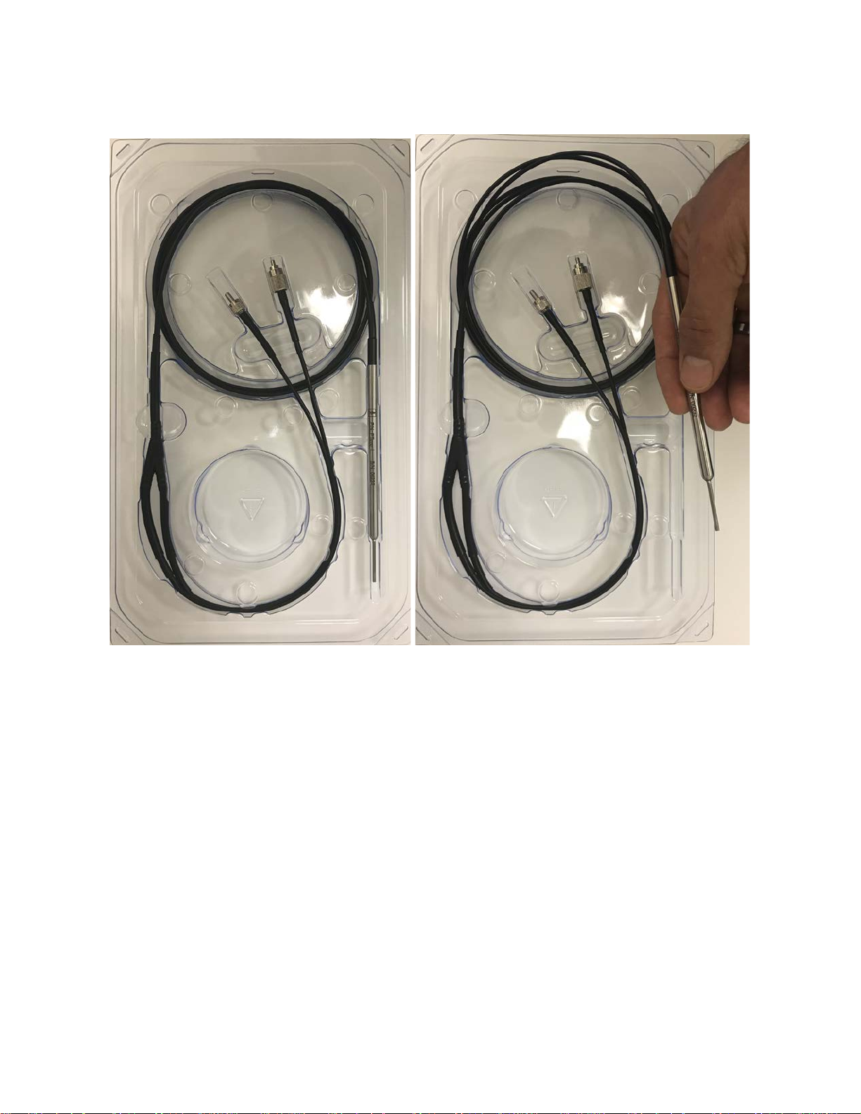
1.5.2 Verifying Probe Assembly Function
The probe ass em b l y co ntai n s d eli cat e fi b er o p t i c cab l es. T o veri fy t h at t hes e h av e n ot b een damaged
during the shipment process, follow these steps.
1. Inspect the probe sterile package for any signs of damage. If any damage is found, discontinue
using the probe and return the probe to AiBiomed.
2. Inspect the probe for any signs of damage, particularly paying attention to the probe tip. If any
damage is found, discontinue usi ng the probe and return the probe to AiBiomed.
Without compromising sterility, follow instructions in section-4 to take all 5 baseline data points with the
probe pointed towards the ground so as to get a low measurement on purpose. Apply the tip of the probe
to any sterile drape available or the probe tray Tyvek lid. The Detection Ratio at the upper right-hand
corner of the display must increase to a greater number when the probe is applied to a fluorescent source,
indicating proper probe function. If the Detection Ratio is below 0.2, the probe may be damaged, and you
should discontinue using the probe, return the probe to AiBiomed and use an alternative probe.
Note: AiBiomed recommends that you purchase additional probe assemblies so that a backup i s avai l ab l e
in case one is dropped or becomes unsterile during an operation.
1.6 Returning the System
If it becom es n eces s ary t o retu rn t h e d ev i ce, al way s u s e the o ri gin al packaging . Th e manu fact u rer d o es
not take responsibility for damage that has occurred during transportation if the damage was caused by
inadequate transport packaging. Please make sure that all required information has been supplied. Call
AiBiomed for a RMA Number for the device return for service.
• Owner’s Name
• Owner’s Address
D121254_EN Rev L PTeye Instructions for Use
Page 11

Page 11 of 48
• Owner’s Daytime Telephone Number
• Device type and model.
• Serial Number
• Detailed exp l an at i o n o f the d am ag e.
Note: The PTeye Console shall be cleaned per section Cleaning prior to returning for service.
AiBiomed shall not implement repairs on equipment which is not returned cleaned.
D121254_EN Rev L PTeye Instructions for Use
Page 12

Page 12 of 48
2 System Installation
2.1 Connecting Peripherals to the Back
The Figure 1 illus t rat es a vi ew o f PTey e co n s o l e fro m the back .
Figure 1: PTeye Console Back
Note: The purpose of potential equalization is to equalize potentials between different metal parts
that can be touched simultaneously or to reduce differences of potential which can occur during
operation b et ween t h e b o d i es of medi cal electrical d ev i ces an d co n du ct ive parts of oth er o bject s .
To begin the installation, follow these steps:
3. Unpack the devi ce an d place it in the locati on w her e i t will b e used . B ecau s e t h e s p eak er i s on the
bottom of the console, the device should be located on a rigid surface.
Note: Make s u re the device location meets the requirements listed for the operating environment in
Section 9.2.4.
4. Connect the external power supply to the back of the console.
5. Plug the power cord into a properly grounded main supply outlet with voltage and frequency
characteristics compatible with those listed on the unit/power supply. Warning: Do not turn on the
device yet.
Warning: Equipment grounding is vital for safe operation. Do not use plug adapters or extension
cords. Th es e d ev i ces d efeat the safety ground and could cause injury.
D121254_EN Rev L PTeye Instructions for Use
Page 13
Page 13 of 48
6. Connect the foot pedal to the back of the console by aligning the red dot on the connector with the
red dot on the mating connector in the back of the System as shown in Figure 2 below.
Note: To disconnect the Foot Pedal, pull on the textured nut outwards to unlatch.
Figure 2: Foot Pedal with Connector Orientation
2.2 Connecting Peripherals to the Front of the Console
Figure 3 illustrat es t h e fr on t of th e P T ey e con s ole.
Figure 3: P Te y e C onsole Front
D121254_EN Rev L PTeye Instructions for Use
Page 14
Page 14 of 48
Figure 4: Fiber Optic Probe Assembly
1. Inspect the functionality of the fiber opt ic probe assembly by following the instructions in section
1.5.2 above.
2. Securely connect the fiber optic probe assembly to the console.
D121254_EN Rev L PTeye Instructions for Use
Page 15

Page 15 of 48
Connect to left
Connect to middle
Figure 5: Probe Assembly Connecto rs
of console
side of console
• Connect the laser cable, which has the smaller end (at the top of Figure 5), to the connector
in the middle of the console.
• Connect the detector cable, which has the larger end (at the bottom of Figure 5), to the
connector on the left side of the console.
3. Plug the power cord into a grounded power source. When power is supplied to the unit, the power
switch should be lit.
3 Pre-Operative Steps
Before attem p t ing to use the PTeye, make sure you have read t h e en t i re I FU and p ay s p eci al att ention to
the warnin g s ection. Then comp l ete these steps :
1. Visually in s p ect th e fiber optic prob e as s em bly to en s ure th ere ar e no v i s ible cuts, cracks, or other
damage. In s p ect al l cabl es as w el l.
2. Make sure that the foot pedal and the probe assembly have been properly connected to the console
before turning the unit on.
3. Turn the power switch to the ON position. The unit should emit a startup beep. Verify that the unit
is working by observing the display. The console screen should look like the one in Figure 6 on
page 16.
4. After turning the unit on, make sure that the foot pedal works properly by pressing the foot pedal
and verifying that the laser LED is lit when the foot pedal is pressed.
5. Turn the unit off and on again in order to clear all data points taken in the previous testing step.
6. Make sure the volume control buttons work correctly and are set at an appropriate volume level.
D121254_EN Rev L PTeye Instructions for Use
Page 16

Page 16 of 48
4 Operating the PTeye
This system was designed with several feedback m ech an i s m s to alert the users in a most intuitive manner.
Correlated audio beeps and on-s creen d i s p l ay i n dicat o rs ref l ect t h e s am e inf or m at i o n duri n g data
collection.
4.1 Collecting Baseline Thyroid Data
The AiBiomed Model PTeye device operates on the principle that the fluorescence of parathyroid tissue is
significantly higher than thyroid.
Before you can use the device to detect parathyroid tissue, you must collect baseline data for the thyroid.
This is done while the screen in Figure 6 displays.
Figure 6: Sample Thyroid Baseline Screen
The various elements on t his screen include the following:
1. A set of 5 num ber icons light up to confirm when a data point has been captured.
2. A display shows the current speaker volume.
D121254_EN Rev L PTeye Instructions for Use
Page 17

Page 17 of 48
3. A display shows the raw data received by the probe assembly when it is being used. This
information is useful for technical troubleshooting.
Collecting baseline data is done by placing the probe assembly gently on thyroid tissue and pressing the
foot pedal. This captures the first data point. You then continue by clicking the foot pedal four more times
at four different locations on the thyroid tissue. The system provides bot h audible and visual feedback to
confirm your actions.
To acquire baseline data for the thyroid using the probe, follow these steps:
1. Make sure you have followed all the pre-operative steps including inspecting cords and plugging in
the probe.
2. Turn the system on using the power switch.
3. The system initializes and sounds a unique beep to indicate it is waiting for the first data point to
establish the thyroid baseline. The data point indicators (1-5) are initially grey.
4. Gently apply the tip of the probe to make contact wi t h the thyroid tissue. If the thyroid has been
previously removed or ablated, muscle or trachea tissue may be used instead of the thyroid tissue.
Note: The PTeye requires the probe to be in direct contact with the tissue of interest for proper
signal recording. If thyroid tissue is covered by fat or other tissues, the fat and tissues must be
manually moved out the way and/or the probe maneuvered around these tissues to make direct
contact wi t h area o f i nter es t .
5. For each baseline m eas u rem en t , place the probe firmly but gently in contact with the thyroid tissue,
holding it in one spot for at least 1 second to ensu re accurate measurement. Then press the foot
pedal once to activate the probe assembly and acquire the first baseline data point. The red LED
laser-on light is lit when the foot pedal is pressed, indicating the laser is on.
The first data point indicator will light up on the console and the system emits a beep. The detection
level asso ci ated with the d at a poi n t col l ect ed is then recorded under neath.
6. Continue to acquire the remaining four baseline measurements by placing the probe tip firmly but
gently in contact with 4 more distinct locations in the thyroid tissue, and pressing and releasing the
foot pedal four more times.
Note: Make sure that you point the probe at 5 different regions of thyroid tissue to ensure an
accurate bas el i n e read i n g . This is import an t becaus e t h e s y s t em selects the medi an value of
fluorescence from all 5 thyroid data points. This takes into account the variability of signal emitted
by the thyroid and the possibility that the probe may have accident al l y touched tissue that is not
thyroid (muscle, fat, etc.). If thyroid tissue is not seen in the patient, ensure that baseline readings
are taken on 5 different regions from one t iss ue type consistently – trachea or muscle.
7. If at any time you are interrupted or want to start over, turn the console off and on again to clear
any collect ed data and start a n ew measurement. Upon restart, the system sets all data point icons to
grey. Please note that the system shou ld be restarted fo r each n ew p atient to reset t h e basel i n e
reading.
D121254_EN Rev L PTeye Instructions for Use
Page 18

Page 18 of 48
Figure 7: Three Data Points Captured
Once you have collected the 5 baseline points from 5 distinct thyroid locations, the system calculates th e
median of the five points to establish a Baseline for the thyroid signal and then becomes continuously
active and searching for any fluorescence si g n al s that exceed t h is m edian thyroid signal.
4.2 Detecting Parathyroid Tissue
Once the baseline thyroid value has been calculated, a new operational screen will display to support
continuous parathyroid search mode. To operate in this mode, the foot pedal must be pressed in order to
activate t h e l as er. When laser emis s i o n is t aking place the ‘LASER ON’ LED at the front of the system
will illuminate .
Once suspect parathyroid tissue has been located visually by the surgeon, the PTeye can be used to
confirm identification of the visually identified suspect tissue.
Responses indicating parathyroid tissue are communicated to the user through a bar graph, a detectio n
ratio, and audio feedback. The full bar graph, and the highest frequency beeps indicate at least 2.5-times
the Baseline which is the median of the 5 thyroid measurements taken during the baseline stage.
The Detection Level i n th e upper left-hand corner of t he screen displ ays the raw data being received by
the probe. The Baseline is a constant value and remains visible at the lower left-hand corner of the screen.
Note: If th e calcul at ed median is les s t han 9, th e PTey e s el ect s 9 as the Baselin e. Th e ran g e o f the 5
thyroid data points collected is then shown underneath.
Figure 8 shows an example screen when it is in use. In this example, the Detection Level is 90 with a
Baselin e o f 4 5. The Detection Ratio is 2.0 which is the Detection Level (90) divides by the Baseline (45)
D121254_EN Rev L PTeye Instructions for Use
Page 19

Page 19 of 48
90/45= 2. 0. The higher t h e Det ect ion Level is, the hig her th e fluorescence ratio of the parathyroid to that
of the thyroid. The bar graph is an alternate way to view the same information in graphical form where
full bars indicate a Detection Ratio of 2.5 or more.
Figure 8: Parathyroid Data Operational Screen
1. Press the foot pedal to keep the laser active. During parathyroid detection, you must keep the foot
pedal continuously pressed in order for the laser to emit. As long as the foot pedal is pressed, the
‘LASER-ON’ LED will illuminate when the laser is emitting.
2. Using the probe, gently apply the tip firmly but in gentle contact with a suspect parathyroid tissue
area. Ensure that the probe is held on that one spot for at least 1 second to ensure accurate
measurement.
Note: If suspect parathyroid tissue is covered by fat or other tissues, the fat and tissues must be
manually moved out the way and/or the probe maneuvered around these tissues to make direct
contact wi t h area o f i nter es t .
3. When using the probe, both the audio and display feedback will assist you in locating the
parathyroid. The audio feedback for parathyroid tissue with a detection ratio of 1.2 to 1.4 emits
sounds with slow beep frequency (one beep per second). As the detection ratio increas es , the beeps
continue to emit more rapidly until it reaches the maximum detection ratio of 2.5.
Note: A healthy parathyroid is very small, approximately the size of a grain of rice. This means
that parathyroid fluorescence can be measured from a very smal l area itself. The probe n eeds to be
positioned accordingly at various regions to confirm parathyroid identification within a larger area.
4. The on-screen bar graph and Detection Ratio correlate directly with the audio. When using the
probe on non-parathyroid tissue, the display shows m ostly yellow and a low detection ratio (<1.2).
D121254_EN Rev L PTeye Instructions for Use
Page 20

Page 20 of 48
When using the probe on parathyroid tissue, the display feedback shows an increasing number of
green bars as the detection ratio increases above 1.2 until it reaches the maximum of 2.5.
When you have completed your measurements on a given patient, turn the system off, detach and discard
the probe assembly.
5 Maintenance
Regular and proper maintenance of your AiBiomed P Teye device is the best way to protect your
investment and avoid non-warranty repairs.
Recommended care and handling of the console includes proper day-to-day operation and cleaning. This
is important to ensure safe an d efficient operation. It is also important to visually inspect the probe
assembly and cables before each use.
Your authorized AiBiomed service department is the most knowledgeable about the PTeye system and
will provide competent and efficient service. Any services and/or repairs done by any unauthorized repair
facility m ay res u lt i n reduced p erfo rmance of the i ns trument or instrument failure.
5.1 L if e Expectancy
The standard warranty for this product is twelve months for the console. Life expectancy for the product
is expected to meet and exceed this period under normal use and standard of care.
5.2 Periodic Maintenance
The PTeye req uires two types o f perio d i c m ai nt enan ce:
1. Regular inspection. The product should be inspected prior to and after each use to en s u re that none
of the connections are damaged or worn. Notify your AiBiomed Sales Repres en t at ive if service is
required.
2. Annual calibration. The system will be calibrated by verifying that it responds correctly to a known
fluorescent material.
5.3 Cleaning
Console, Power Cord, Cable(s) and Footswitch Cleaning Instructions
Follow the warnings, cautions, and instructions below. It is recommended that the oper ator clean
the Console, Power Cord, Cable(s) and Footswitch unit prior to each use or as needed. The
probe assembly is non-reusable and should be discarded after one use.
To avoid electri c shock an d pot entia ll y fat al injury, d iscon n ect th e con sol e from the
AC power source before clea n in g.
D121254_EN Rev L PTeye Instructions for Use
Page 21

Page 21 of 48
Observe the following cautions to avoid damagin g th e console:
• Do not sterilize the Co n sole, P ower C ord, Ca b le(s) an d Footswitch
• Do not immerse the Console, Power Cord, Cable(s) and Footswitch in any liquid.
• Do not allow liquid to drip onto the Console, Power Cord, Cable(s) and Footswitch
or collect on any of its surfaces.
• Do not spray cleaning liquid directly onto the Console, Power Cord, C ab le( s) and
Footswitch. Place the cleaning liquid onto a cloth, and use the cloth to wipe the
console.
• Do not use corrosive cleaning solutions to clean the Console, Power Cord, Cable(s)
and Footswitch
5.3.1 Cleaning the Console, Power Cord, Cable(s) and Footswitch
1. Turn the power switch off. Disconnect the power cord from the electrical power source and
from the rear of the Console.
2. Place a mild (neutral) detergent onto a dry, soft cloth. Do not saturate the cloth.
3. Wipe the Console, Power Cord, Cable(s) and Footswitch with the dampened cloth. Do not
allow liquid to drip from the cloth or collect on the console.
4. When cleaning the front LCD screen, use extra care to prevent liquid from dripping or
pooling on the bottom of the screen.
5. Visually inspect the external surface of the device for cleanliness, focusing on hard-to-
reach areas. If visibl e soil remain s, repeat steps 1– 3.
6 Compatible Peripherals
• PTeye-1 Probe Assembly
• PTeye-2 Foot Pedal
• PTeye-3 Power Supply
• PTeye-4 Power Cord 125V or PTeye-5 Power Cord 250V depending on the country the system is
sold in.
7 Troubleshooting
Use this section to help diagnose the cause of unexpected behavior of the PTeye.
System fails to detect any p arat hyroid tissue
If you take five baseline data points from one tissue location and that location is parathyroid, the system
will fail to detect parathyroid tissue because the baseline is wrong. You should always take the points
from 5 separate and distinct locations of thyroi d tissue to ensure a valid range of readings. If this situation
occurs, turn the unit off and on again and recapture the 5 baseline data points following the recommended
approach.
D121254_EN Rev L PTeye Instructions for Use
Page 22

Page 22 of 48
Failure to detect parathyroid tissue can also occur if the foot pedal is not pressed while searching for
parathyroid tissue. Pressing the foot pedal act i v at es the laser, which is an es s en tial p art of the system
operation.
In rare cases, s o m e u n fi lt ered s u rg i cal l ights emit NIR light, which may be observed when the on-screen
bar graph goes green when the probe is not in contact with tissue after baseline measurement in that
patient. These surgical lights can interfere wi t h s yst em perform an ce and regis t er a s i g n al sim i l ar t o th e
parathyroid. Room lights and surgeon’s head-lamp/headlight are known to not cause this phenomenon. In
such situations, keep the room lights and surgeon’ s head-lamp/headlight ON, and turn off the surgical
lights while tak ing tissue measurements.
System detects parathyroid tissue when pointed at a light
If the probe is directed at a light so u rce t h at has s p eci fic wav el en g t h an d f req uen cy ch aract eristi cs , the
system may indicate that parathyroid is detected. This is misuse of the device; the probe should only be
pointed at thyroid and parathyroid tissue and the surgical field, such that the probe placed in contact with
the tis sue of interest for accurat e r es ults.
System is producin g unexpected signal no matter where it i s pointed in the Operating Room.
In rare cases, s o m e u n fi lt ered surgical lights emit NIR light, which may be observed when the on-screen
bar graph goes green when the probe is pointed in the operating room, after the baseline measurement in a
patient. These surgical lights can interfere with system performance and register a signal similar to the
parathyroid. Room lights and surgeon’s head-lamp/headlight are known not to cause this phenomenon. In
such situations, keep the room lights and surgeon’s head-lamp/headlight ON, and turn off the surgical
lights while taking tissue measurements.
System continuo us ly in dicates parathyroid tissue or detects parathyroid when you know it is
thyroid
Try turning the system off and on again and recollecting the 5 thyroid data poi nts, making sure you are
measuring the baseline from 5 different locations of the thyroid.
In rare cases, some unfiltered surgical lights emit NIR light, which may be observed when the on-screen
bar graph goes green after the baseline measurement in a patient. So even when the probe is in contact
with thyroid tissue, these surgical lights can interfere with system per fo rm an ce an d r egister a signal
similar to the parathyroid. Room lights and surgeon’s head-lamp/headlight are known to not cause this
phenomenon. In such situations, keep the room lights and surgeon’s head-lamp/headlight ON, and turn
off the surgical lights while taking tissue measurements.
If the problem persists, contact AiBiomed Customer Service.
D121254_EN Rev L PTeye Instructions for Use
Page 23

Page 23 of 48
Pressing the foot pedal does no t capt ure a data point.
Make sure t he foot pedal is securely connected to the PTeye Console. If the problem persists, contact
AiBiomed Customer Service. .
8 End of Life Environmental Directives
WEEE Directive [2002/96/EC] on
Waste El ect ri cal and Elect ro n i c Eq ui pment
The Directi v e on Was t e E l ectrical and Elect ro nic Equipment o b lig es m an u fact u rers , importers, and/or
distributors of electronic equipm ent to provide for recycling of the electronic equipment at the end of its
useful life.
Do not dispose of WEEE in unsorted municipal waste.
The WEEE symbol on the product or its packaging indicates that this product must not be disposed of
with other waste. Instead, it is your responsibility to dispose of your waste equipment by handing it over
to a designated collection point for the recycling of Waste Electrical and Electronic Equipment. The
separate coll ection and recycling of your waste equipment at the time of disposal will help conserve
natural res ou rces an d en s u re t h at it i s recycl ed i n a manner th at p ro tects human heal t h and t h e
environment. For more information about where you can drop off your medical equipment at t he en d of
its usef ul l i fe fo r r ecy cl i n g , please contact A iBiomed Custom er Service Departm en t.
9 Technical Inform a tion
9.1 Theory of Operation
The PTeye device is based on an intraoperative techniq u e t h at u s es near-in frared (NIR) autofluorescence
for in vivo, real-time confirmation of visually suspected parathyroid tissue regardless of its pathologic
state. I t is bas ed o n the p rinciple of intrinsic fluorescence, which is an inherent property of human tissue.
Fluorescence by definition is emitted energy that results from excitation energy at a lower wavelength. In
the PTeye s y stem, the excitati o n w av el en g t h is 78 5n m. The fl u o res cen ce (fo r t h e PTeye, it i s bet t er s t ated
as auto-fluo res cen ce s ince no extern al d y es are u s ed) occurs at a p eak o f 8 2 2 nm and ranges from 808nm
through 1000nm.
This instrument consists of a few basic components including a portable fiber-optic probe, a l as er s et t o
785nm, a foot pedal, a detector, processor boards, and a power supply. The system utilizes the operating
principle by prompting the user to take baseline measurements from known thyroid tissue and then
allowing them to use the probe as a scanning device to provide sensitive, real-time parathyroid detection
during procedures.
D121254_EN Rev L PTeye Instructions for Use
Page 24

Page 24 of 48
The system establishes the baseline by initially prompting the user to acquire five points of the thyroid
tissue at the start of each procedure and calculating the m edian of those five points.
Once the basel ine data point s are acqu i red an d t h e b as el i n e res p o n s e es t ab l ish ed , the system beco m es
continuously active and searches for any fluorescence signals that exceed the baseline response. Higher
responses indicate higher fluorescence of parathyroid relative to the thyroid. Responses indicating
parathyroi d t i s s u e are co mm u nicated to the user in multiple ways:
1. Visually through a bar graph that increases in amplitude depending on the ratio of a given measured
fluorescence to a predefi n ed b as el i n e (t h y ro id tissue level flu or es cence) . A s t h e rat io increases, s o
does the bar graph amplitude. A detection ratio display follows the same logic as the bar graph.
When using the probe on non-parathyroid tissue, the graph shows mostly yellow and a low
detection ratio (<1.2). When using the probe on parathyroid tissue, the display feedback shows an
increasing n u m b er o f g reen b ars as the d et ect i o n rat i o increas es ab o ve 1 .2 until it r eaches the
maximum of 2.5.
2. The system also ind i cat es the same inform at i on as the visual display by emitting auditory feedback
via a speaker. The tone frequen cy increases as t he r at i o descri b ed i n i t em 1 in creas es . The on-screen
display graph and detection ratio correlate directly with the audio.
The device i s calibrated s u ch that t h e full bar graph, and the highest frequency beeps indicate that the
parathyroid fluorescence is at least 2.5 times the median of the five thyroid measurements taken during
the baseli n e s t ag e.
9.1.1 Energy
The system emits non-ionizing laser at 785nm (NIR) at the tip of the probe directly at tissue whether
thyroid or otherwise. The maximum power of the emitted laser is 20mW.
9.1.2 Disease
The instrument will be used in thyroidectomy and parathyroidectomy procedures.
9.2 T echnical Specifications
9.2.1 General
IEC Equipment Classification: Type BF, Class I, continuous operation.
Typical Operating Requirements:
Input Voltage: 100 - 240 VAC
Frequency: 50/60 Hz
Power Consumption: 120 VA
D121254_EN Rev L PTeye Instructions for Use
Page 25

Page 25 of 48
Line Frequency Leakage: Chassis to Ground (120VAC): < 100μA
9.2.2 Laser
The syst em emits non-ionizing laser at 785nm (NIR). The maximum power of the emitted laser is 20mW.
The pulse duration is 0. 32 ms. The maximum beam divergence angle is 25 degrees.
9.2.3 Dimensions
Size (approximate di mensions)
Console: 14 in x 8.5 in x 6 in
Probe Assembly Length: 2.2 meters
Weight (approximate weight)
Console: 15 lb.
Probe Assembly: 1 lb.
9.2.4 Environmental
Operating Environment
Ambient Temperature: (-10°C to 30°C)
Relative Humidity: 30% to 90% non-condensing
Atmospheric Pressure: 700 hPa to 1060 hPa
Transport and Storage
Ambient Temperature: (- 29°C to + 60°C)
Relative Humidity: 15 to 85% non-condensing
Atmospheric Pressure: 500 hPa to 1060 hPa
Meet transportation vibration requirements
9.2.5 IP Ingress Class
IPX0 -Ordinary for Console
D121254_EN Rev L PTeye Instructions for Use
Page 26

Page 26 of 48
IPX7 for Prob e
9.2.6 Safety Testing
UL60601-1
CSA C22. 2 No. 601-1-M90
EN 60601-1
IEC 60601-1
9.2.7 Power Cord Requirements
125V 10 Amp (PTeye-4). Use only a listed (UL, CSA) detachab l e p o w er co rd.
250V 10 Amp (PTeye-5). Use only an agency approved detachable power cord.
10 Software Version Access
The Instal l ed Sof t war e Vers i o n is visibly seen upon system power at the bottom right corner of the
display.
11 Detailed EMC Information
This equipment has been t es ted and found to comply with the Class A limits for medic al dev ic es to t he
EN 60601-1 and EN60601-1-2. These limits ar e des igned to prov ide reasonable protection against
harmful interf er enc e in a typic al m edic al ins tallation. This equipment generates uses and can radiate
radio frequency energy and, if not installed and used in accor danc e with the instructions, may caus e
harmful interf er enc e to other device(s) in the vicinit y . However, there is no guarantee that interfer enc e
will not occur in a partic ular ins tallation. If this equipment does c aus e har mful interference to other
devices, which can be det er m ined by turning the equipment off and on, the user is encouraged to try
to correct the int erfer enc e by one or more of the following measures:
(a) Reorient or relocate the receiving device.
(b) Increase the separ ation between the equipment.
(c) Connect t he equipm ent into an outlet on a circuit diff er ent f r om that t o whic h the ot her dev ic es ar e
connected.
(d) Consult the manufac turer or field service technician for help.
DETAILED EMC INFORMATION
NOTE: CE marked equipment has been t est ed and foun d t o co mpl y with the EMC limits for t he
Medical Device Direct ive 93/42/EEC [EN 55011 Class A and EN 60601-1-2]. These li mits are
designed to provid e reason abl e pro t ect io n ag ain st harmf ul interference in a typical medical
installation.
The Equipment generat es and c an r adiate radio frequency energy and, if not ins talled and used in
accordance with the ins tructions, may cause harmful interf er enc e to other devices in the vicinit y.
However, there is no guar antee that interferenc e will not occ ur in a partic ular ins tallation. If this equipment
does cause harmful int er ference with other devices, which c an be determined by turning the equipment
D121254_EN Rev L PTeye Instructions for Use
Page 27

Page 27 of 48
off and on, the user is encouraged t o try to correct the interference by one or more of the following
Guidance and manufacturer’s declaration – electr om agnetic e mission s
environment.
Emissions Test
Compliance
Electromagnetic environment- guidance
low and not likely to cause any interference in nearby equipment.
the eq uipment.
measures:
• Reorient or r eloc ate the receiving device.
• Increas e the separation between t he equipm ent.
• Connect t he equipm ent to an outlet on a circuit different from that to which the other devic e( s ) is
connected.
• Consult t he m anufacturer or a field service t ec hnic ian for as s is tance.
NOTE: The EMC tables and other guidelines that are included in the Instruction Manual provide
informa t io n t o the customer or user that is essential in determining the suit abi li t y of the
Equipment or System for the Electro-magnetic Environment of use, and in managing the
Electrom a gnetic Environment of use to permit t he Equipment or System t o pe r for m it s intended
use without disturbing other Equipment and Systems or non-medical electrical equipment.
NOTE: Medical Electrical Equipment needs special precautions regarding EMC and needs to be
installed and put into service according to the EMC information provided in the Accompanying
Documents.
WARNING: Portabl e RF communi cation s equ ip ment ( in cluding peripherals such as antenna
cables and external an t enn as) should be used no closer than 30 cm (12 inches) to any
part of the AiBiomed Parath yroi d Detect ion System (PTeye), including cables
specified by the manufacturer. Otherwise, degradation of the performance of this
equipment could result .
WARNING: Use of accessories, transducers and cables oth er than tho se speci f ied or provided by
the manufacturer of th i s equipmen t could result in increased electromagnetic
emissions or decreased electromagnetic immunity of this equipment and result in
improper operation.
WARNING: Use of this equipment adj acent to or stacked with other equipment should be avoided
because it could result in improper operation. If such use is necessary, this
equipment and the other equipment should be observed to verify that they are
operating normally.
Table 201
The AiBiomed Parathyroid Detection System is intended for use in the electromagnetic environment specified below.
The customer or the user of the AiBiomed Parathyroid Detection System should assure that it is used in such an
RE emissions
CISPR 11
RF emissions
CISPR 11
D121254_EN Rev L PTeye Instructions for Use
Group 1 The AiBiomed Parathyroid Detection System uses RF energy
only for its internal function. Therefore its RF emissions are very
Class A The EMISSIONS characteristics of this
equipment make it suitable for use in industrial areas
and hospitals (CISPR 11 class A). If it is used in a
residential environment (for which CISPR 11 class B
is normally required) this equipment might not offer
adequate protection to radio-frequency
communication services. The user might need to
take mitigation measures, such as relocating or reorienting
Page 28

Page 28 of 48
Table System Cables
Type
Use
Shielded?
Ferrite?
Maximum Length
PTeye Power Cord Supply Line Power to
Supply
Power Supply
PTeye Console
PTeye Console
the External Power
No No 2 M
PTeye External
PTeye Foot Pedal Allows for control of the
Supplies power to the
No Yes 1.5 M
No No 3.6 M
Table 202
Guidance and manufacturer’s declaration – electromagnetic immunity
The AiBiomed Parathyroid Detection System is intended for use in the electromagnetic environment specified below. The
customer or user of the AiBiomed Parathyroid Detection System should ass ure that it is used in such an environm ent .
Immunity Test IEC 60601 test level Complia nc e Level Elec t r om agnetic env ironment - guidance
Electrostatic discharge [ESD]
IEC 61000-4-2
Electrical fast transient /
burst
IEC 61000-4-4
Surge
IEC 61000-4-5
± 8 kV contact
± 15 kV air
± 2 kV differential
mode
± 1 kV for input /
output lines
± 1 kV differential
mode.
± 2 kV common mode.
± 8 kV contact
± 15 kV air
± 2 kV differential
mode
± 1 kV for input /
output lines
± 1 kV differential
mode.
± 2 kV common mode.
Floors should be wood, concrete or ceramic tile.
If floors are covered by synthetic material the
relative humidity should be at least 30%.
Mains power should be that of a typical
commercial or hospital en viro nm ent.
Mains power should be that of a typical
commercial or hospital environment.
Voltage dips, short
interruptions and voltage
variations on power supply
input lines
IEC 61000-4-11
Power Frequency [50/60 Hz]
T
=0%; 0.5 cycl e.
U
(0°, 45°, 90° , 13 5°,
180°, 225° , 27 0° and
315°),
T
=0%; 1 cycle.
U
T
U
=70%; 25/30 cycles.
(At 0°)
T
U
=0%; 250/ 300
cycles.
UT=0%; 0.5 cycl e.
(0°, 45°, 90° , 13 5°,
180°, 225°, 270° and
315°),
T
=0%; 1 cycle.
U
T
U
=70%; 25/30 cycles.
(At 0°)
T
U
=0%; 250/ 300
cycles.
30 A/m 30 A/m Power frequency magnetic fields should be at
magnetic field.
IEC 61000-4-8
NOTE: UT is the a.c. mains voltage prior to application of the test level.
Mains power should be that of a typical
commercial or hospital environment. If the user
of the AiBiomed Parathyroid Detection System
requires conti nu ed op erati on dur i ng pow er
mains interruptions, it is recommended that the
AiBiomed Parathyroid Detection System be
powered from an uninterruptible power supply
or a battery.
levels character i stic of a typic al lo c ation in a
typical commercial or hos pita l envir on m ent.
D121254_EN Rev L PTeye Instructions for Use
Page 29

Page 29 of 48
Table 204
Guidance and manufacturer’s declaration – electromagn et ic im m un ity
such an environm ent.
Test
level
Recommended separation distance
4-6
and reflection by structures, objects and people.
Over the frequency range 150 kHz to 80 MHz, field strengths should be less than 3 V/m.
[ ]
P
Vd 1
/5
.3=
P
[ ]
P
V
d 1
/5
.
3=
P
[ ]
P
The AIBIOMED PARATHYROID DETECTION SYSTEM is intended for use in the electromagnetic environment specified
below. The customer or user of the AIBIOMED PARA THYR OID DETECTION SYSTEM should assure that it is used in
Immunity
Portable and mobile RF communications equipment should
Conducted
RF
IEC 61000-
Radiated RF
IEC 61000-
4-3
Where P is the maximum output power rating of the
IEC 60601 test level Compliance
3 Vrms
150 kHz to 80 MHz
3 V/m
80 MHz to 2.7 GHz
V1=3 Volt
V2=6 Volts in
ISM bands
E1= 3 V/m
Electr om a gn etic env ironm en t – guidance
be used no clo ser to any part of th e AiBiomed Parathyroid
Detection System, including cables, than the recommended
separation distance calculated from the equati on app li cab le
to the frequency of the transmitter.
= 1.17
=1.17 80 MHz to 800 MHz
PEd 1
/7=
transmitter in watts [W] according to the transmitter
manufacturer and d is the recommended separation in
meters [m].
Field strengths from fixed RF transmitters, as determined by
an electro magneti c si te su rv ey,
compliance level in each frequency range.
Interference may occur in the vicinity of equipment marked
with the following symbol:
= 2.33 800 MHz to 2.5 GHz
a
should be less that the
b
NOTE 1: At 80 MHz and 800 MHz, the higher frequency range applies.
NOTE 2: These guidelines may not apply in all situations. Electromagnetic propagation is affected by absorption
a
Field strengths from fixed transmitters, such as base stations for radio [cellular/cordless] telephones and land
mobile radios, amateur radio, AM and FM radio broadcast and TV broadcast cannot be predicted theoretically
with accuracy. To access the electromagnetic environment due to fixed RF transmitters, and electromagnetic
site survey should be considered. If the measured field strength in the location in which the AiBiomed
Parathyroid Detection System is used exceeds the applicable RF compliance level, above, the AiBiomed Parathyroid
Detection System should be observed to verify normal operation. If abnormal performance is observed,
additional measures may be necessary, such as reorienting or relocating the AiBiomed Parathyroid Detection
System.
b
D121254_EN Rev L PTeye Instructions for Use
Page 30

Page 30 of 48
Table 206
PARATHYROID DETECTION SYSTEM
maximum output power of the communications equipment.
0.01
0.12
0.12
0.23
0.1
0.37
0.37
0.74
1
1.17
1.14
2.33
10
3.70
3.70
7.37
100
11.70
11.70
23.3
and reflection from structures, objects, and people.
[ ]
PVd
1/5.3=
[ ]
P
E
d 1/
5.3=
[
]
Recomm en de d se paratio n dis tances be tw e en p or ta bl e and mobile RF communications equip m ent and the AIBIOMED
The AiBiomed Parathyroid Detection System is intended for use in an electromagnetic environment in which radiated RF
disturbances are controlled. The customer or the user of the AiBiomed Parathyroid Detection System can help prevent
electromagnetic interference by maintaining a minimum distance between portable and mobile RF communications
equipment [transmitters] and the AiBiomed Parathyroid Detection System as recommended below, according to the
Rated max im um
output power of
transmitter [W]
For transmitters rated at a maximum output power not listed above, the recommended separation distance [d] in
meters [m] can be estimated using the equation applicable to the frequency of the transmitter, where P is the
maximum output rating of the transmitter in watts [W] according to the transmitter manufacturer.
NOTE 1: At 80 MHz and 800 MHz, the separation distance for the higher frequency applies.
NOTE 2: These guidelines may not apply in all situations. Electromagnetic propagation is affected by absorption
150 kHz to 80 MHz
Separation distance according to frequency of transmitter [m]
80 MHz to 800 MHz
800 MHz to 2.5 GHz
7
=
P
Ed
1/
D121254_EN Rev L PTeye Instructions for Use
Page 31

Page 31 of 48
12 Summary of Clinical Information
Demographic
Variables
Site A
Site B
Overall
Number of patients
40
hyperparathyroidism)
41
81
hyperparathyroidism)
SUMMARY OF CLINICAL INFORMATION
A. Study Design
A clinical study was conducted to support the safety and effectiveness of the AiBiomed
Parathyroid Detection System (PTeye) to aid in the identification of parathyroid (PG)
tissue during t hyroi d and parathyroid surgical procedures.
The single blinded non-randomized study was conducted at two centers, Vanderbilt and
Ohio State University Medical Center and included ti ssue measurements during thyroid
and parathyroid surgical procedures. Measurements were taken intraoperatively by
surgeons who were blinded to PTeye device output. During the surgical procedure, five
thyroid data points were initially collected by touching the probe tip to the thyroid tissue.
The system used these 5 points to calculate a baseline near infrared autofluorescence
(NIRAF) medi an value and t hi s establ ished t he reference b aselin e f or each in di vi dual
patient. If no thyroid tissue was present due to a previous thyroidectomy/thyroid ablation,
baseline NIRAF median w as alter n ati vel y o bt ain ed on neck mu scle or tr ach ea for that
particular pat ien t. S ubsequ ent ti ssue NI RAF m easur emen ts i n t he pat i ent were th en
normalized to this NIRAF baseline for obtaining the detection ratio. Upon visualizing a
tissue of interest, the surgeon first stated the degree of confidence in having identified
tissue as parathyroid gland with high, moderate or low confidence, based solely on visual
inspection of the tissue-in-situ and without relying on the PTeye device. This information
was recorded for assessing t he performance of the PTeye as compared to the surgeon’s
visual assessment. The surgeon then placed the probe of the PTeye on the suspect tissue
site and pressed the foot-pedal, resulting in tissue NIRAF intensity and detection ratio
being displayed only to the study investigator and not surgeon in real-time.
The study was originally designed to compare the performance of the PTeye to a prior
prototype parathyroid detection system. Of the original 133 patients enrolled, 82 patients
were tested with the PTey e in its fi nal design. There are technological di ffer ences
between the PTeye and the prototype device, including ambient light interference and
peak intensity to det er m in e baseline (NI RAF ), which may al ter the device effectiveness
results. Ther ef ore, effect iv eness resul ts on ly f or the PTey e final d esign wer e con sider ed .
However, for the safety results, both treatment groups are included in the summary
below. Of note, there were no reported surgery or device related adverse events for the 51
patients whose results have been excluded from the final effectiveness analysis.
Subjects enrolled in the study included both men (23.5%) and women (76.5%) over the
age of 18.
Table 1: Summary of Demographic Information
D121254_EN Rev L PTeye Instructions for Use
(38- excluding 2
patients with secondary
(79- excluding 2
patients with secondary
Page 32

Page 32 of 48
Gender
Female
28 (70.0%)
34 (82.9%)
62 (76.5%)
Male
12 (30.0%)
7 (17.1%)
19 (23.5%)
Race
Caucasian
34 (85.0%)
39 (95.1%)
73 (90.1%)
Non-Caucasian
6 (15.0%)
2 (4.9%)
8 (9.9%)
Age (years)
54.3 ± 15.8
52.3 ± 16.4
53.8 ± 19.9
BMI ( kg/m2)
29.3 ± 6.2
31.6 ± 9.2
30.5 ± 7.9
Primary ef fect i v en es s
endpoints
Performance m eas u red b y t h e ab i l i ty o f the PTey e t o accuratel y i dentify
parathyroid glands [PG detection rate].
Secondary eff ect i v en es s
endpoints
Intra-patient and inter-patient variability of NIRAF in thyroid and PGs.
Effect of thyroid and PG pathology on intraoperative parathyroid
Identification.
In-vivo and ex-vivo effect of blood on NIRAF intensity of PG and
would affect parathyroid identification.
Ex-vivo effect of probe-to-tissue con t act press u re o n PG fluo res cen ce
intensity.
Safety Endpoint
Safe use as d et erm i n ed by a lack o f (s eri o u s ) ad v ers e ev en t s .
The addition of no more than 5 minutes to the total procedure time during
normal use of the device.
Clinical Inclusion and Exclusion Criter ia
Inclusion Criteria:
To be eligible for study enrollment , a s u bject was req u ired to satis fy each of the followin g crit er i a.
1. Adults (18-99 years of age) scheduled to undergo parathyroid or thyroid surgery.
2. Willing to sign the informed written consent form.
Exclusion Crite r ia:
A subject was not eligible to participate if they met any of the following exclusion criteria.
1. Pregnant
2. Unsuitable for study participation in the opinion of the Investigator- attending surgeon.
The study was initially designed to evaluate t he performance of the PTeye in differentiating between
parathyroid gland and non-parathyroid gland tissue once a potential candidate tissue was surgically
exposed during the procedure. This was subsequently corroborated by the surgeon’s visual identification
for in situ parathyroid glands using an unvalidated confidence scale (low, medium, or high) and with
histological examination for the excised parathyroid gland tissues.
Table 2: Study Endpoints
thyroid with the PTeye system to assess if a hemorrhagic surgical field
D121254_EN Rev L PTeye Instructions for Use
Page 33

Page 33 of 48
Table 3: Subject Accountability
All Subjects
Final PTey e System
N = 133
N = 82
Completed subjects
-
82
Discontinued subjects
51 (prototype device)
3
Reason for discontinuation
Protocol deviation
a
1
Previously identified disease state
b
2
Enrolled subjects
a
Protocol deviation due to comm unication error between study coordinator and surgeon regarding the
timin g of dep res sing the PTeye foo t ped al l ead i n g to incorrect b as el i n e NIRAF measuremen t s .
b
Patients with secondary hyperparathyroidism were determined to exhibit irregular NIRAF in prior
studies and thus, were excluded fro m the final effective n es s p erfo rm an ce as s es s ment.
The ability of the PTeye to accurately identify parathyroid glands [PG detection rate] included the
following assessments using objective histology and subjective expert surgeon opinion:
PTeye Performance Data Analysis:
1. Sensitivity- Number of true positives, (as determined by PTeye and validated by histology or
surgeon's visual identification with high/moderate confidence)
divided by actual positives (PG
sites – total number of positives as determined by histology or surgeon's visual identification with
high/moderate confidence)
2. Specificity: Number of true negatives, (as determined by PTeye and validated by hi stology or
surgeon's visual identification with high/moderate confidence)
divided by actual negatives (nonPG sites – total number of negatives as determined by histology or surgeon's visual identification
with high/moderate
confidence)
3. PPV: Number of true positives, (as determined by PTeye and validated by histology or
surgeon's visual identification with high/moderate confidence) divided by number of device
positives (total number of pos itives as determined by PTeye alone)
4. NPV: Number of true negatives, (as determined by PTeye and validated by histology or
surgeon's visual identification with high/moderate confidence) divided by number of device
negatives (t o t al number of negat i v es as d et er m i n ed
5. False positi v e ra te: Rate of device pos i ti v e m eas u rem en t s w hen tested on actual
(number of negatives validated by histology or surgeon's visual
by PTeye alone)
identification with
negatives
high/moderate confidence).
6. False negative rate: Rate o f devi ce n eg at i v e m eas u rem en t s w h en tes t ed o n actual
(number of positives validated by histology or surgeon's visual
identification with
positives
high/moderate confidence).
Based on thes e p aram eters, overal l accuracy of the PTeye in PG identif i cat i o n an d
associated k ap p a
values were accor dingly calcu l at ed .
Statistical significance of NIRAF intensities between thyroid, parathyroid gland, fat, muscle and
were determin ed u s i n g a two-tailed Student’s t-test for unequal variance,
with an alpha (level of
trachea
D121254_EN Rev L PTeye Instructions for Use
Page 34

Page 34 of 48
significance) of 0.0 1. T h e same s t atistical app ro ach was ad o p t ed to d et erm i n e if t h ere was a si gn i f i can t
difference b et w een NIRAF measured fro m normal and diseased thyroid and parathyroid glands.
Comparison of surgeon’s visual determ ination versus the PTeye as validated with histology-based
gold standard:
The performance accuracy of the participant surgeons in differentiating between parathyroid gland (PG)
and non-PG tissues relying on their visual skills were compared to that of the PTeye. This was performed
in those cases wh en i n vivo m eas u r em en t s were p erf or m ed on ti s s u es th at were l at er ex ci s ed fo r
histological validation via frozen section or Hematoxylin-Eosin stained tissue section analysis by the
pathologists that could serve as the gold standard. Due to lack of histological validation of in-situ tissues,
these were not considered for comparing performance accuracy between the surgeons and the PTeye. In
addition, comparison of surgeon versus PTeye were evaluated for each investigational site/study center.
All parti cipant surgeon s at bo t h cent ers wer e high-volume surgeons (who perform >25 thyroid surgeries
per year and >15 parathyroid surgeries per year).
Assessi n g va ri a bi l i t y and asso ci a ted factors wit hi n pati ent data acqui red w i th the PTeye:
Following data acquisition and analysis, the report also investigated: (i) t he distribution of demographic
variables at both study centers including: age (18- 99 years of age), gen d er (m al e o r f em al e), race
(Caucasian or non-Caucasian), body-mass index (BMI) at time of surg ery, (ii) Intra-patient and interpatient variability of NIRAF in thyroid and PGs respectively and (iii) the effect of thyroid and parathyroid
disease on i ntrao p erat ive PG iden tif i cat i o n .
Influence of blood on NIRAF of thyroid an d PG:
A. Ex vivo Validation:
The effect of blood on the NIRAF intensity of PG and thyroid was assessed ex vivo with the PTeye in
order to det ermine if a hemorrh ag i c s u rg i cal field would affect P G i d en ti fi cat i o n . T hr ee fres h fro zen
specimens each, of normal thyroid and PG adenoma were obtained from the NIH funded Co-operative
Human Tissue Network (Vanderbilt University Medical C enter, Nashville, TN). After thawing the
specimens , at least six NIRAF measurements wer e ob t ained from each s p eci men ex vivo. To simul ate a
hemorrhagic surgical field, 0.5 cc of heparinized murine blood was introduced on to the specimen surface.
NIRAF intensity of each specimen was measured with the PTeye and normalized to the thyroid NIRAF
and grouped into four categories: (i) thyroid without blood (n, (ii) thyroid with blood, (iii) PG without
blood and (iv) PG with blood, with each group consisting of 18 NIRAF measurements. Statistical
significance was determ i n ed u s i ng a two-tailed Student’s t-tes t for unequal vari an ce, with an alph a level
of signi ficance, alph a of 0.01.
D121254_EN Rev L PTeye Instructions for Use
Page 35

Page 35 of 48
B. In vivo validation:
The influ en ce of a hemorrhagic su rg i cal field on PG identifi cation wit h th e PTey e was also tested in vivo
using 4 PGs from 3 patients. The surgeon upon identifying a tissue thought to be the PG with
high/moderate confidence, obtained PTeye measurement from the tissu e. In t h es e three p at ients –1-2
measurements were taken when the PG was covered with blood, which routinely occurs during the
surgical procedure. After the measurement, the surgeon suctioned the blood away, rinsed the tissue with
saline and rep eat ed t h e PTeye measurement o n the s ame t i s s u e sit e. Detection rat i o s were gr ou p ed fo r
three categories: (i) thyroid, (ii) PG with blood and (iii) PG without blood, with each group consisting of
at least 6 NIR AF m eas u rem en t s . Statistical significance between (i) thyroid and P G without blood and (ii)
thyroid and PG with blood were determined by a 2-tailed Student’s t-test for unequal variance, with an
alpha level of significance of 0.01.
Effect of probe-to-ti s s u e co ntact pressure on tissue NIRAF measuremen ts with the PTeye:
The effect of probe-to-tissue contact pressure on tissue NIRAF intensity was examined in vitro on excised
fresh frozen human PG (n=3) and thyroid (n=2) tissues. NIRAF measurements with the PTeye were
collected where the user reported the probe contact pressures qualitatively to be ‘mild’, ‘moderate’, and
‘high’. Differences in P G det ect i o n rat ios were correlated w i t h the d eg ree o f p ro be-to-ti s s u e con t act
pressure.
Schedul e o f a sses s ments:
There were no form al follow-up assessments or visits for the patient: subj ects exit the study at the
conclusion of standard recovery from the surgical procedure.
Safety def i n itions and repo rti ng requiremen ts :
All advers e ev ents (AEs), regard l es s o f s eri o u s n es s, s everit y , or relationship to the study device, were to
be recorded in the Case R eport Forms (CRF) by the investigators and/or study coordinators and reported
to corresponding IRBs at the two centers and to the Principal Investigator. The evaluation was to include
a determination of the seriousness and severity of the event, whether the event or the severity of the event
was anticipated or unanticipated, and the relationship of the event to the study device.
A serious adverse event (SAE) is defined according to ISO 14155:2003 as any adverse event that:
• Led to a death
• Led to a serious deterioration in the health of the subject that
• Resulted in a life-threatening illness or inj ury
D121254_EN Rev L PTeye Instructions for Use
Page 36

Page 36 of 48
• Resulted in a permanent impairment of a body structure or a body function
• Required in-patient hospitalization or prolongation of existing hospitalization
• Resulted in medical or surgical intervention to prevent permanent impairment to body structure
or a body function
An unanticipated adverse device effect (UADE) is defined per 21 CFR 812.3 as any serious adverse effect
on health or safety or any life-threatening problem or death caused by, or associated with, a device, if that
effect, problem, or death was not previously identified in nature, severity, or degree of incidence in the
investigational plan or application (including a supplementary plan or application), or any other
unantici p at ed s erious problem as s o ci at ed wit h a dev i ce that rel ates to the rig hts , s afet y , o r wel f are o f
subjects.
SAE and UADE were to be reported by the investigators to the IRB and to AiBiomed within 24 hours.
Serious AEs and UADEs were documented on t he Serious Adverse Event Form.
Safety and Eff ectiven ess Result s
1. Safety Results
At the end of patient follow-up period of t wo weeks, no adverse events related to the procedure or during
the study period were reported. There were no adverse events, SAE’s, or UADE’s reported in the 81
patients co n s i d ered fo r ef fect i v en es s d at a an al y s i s. No clinical issu es or ad ver s e even t s related to th e
intra-operative use of the device description of procedural difficulties, or device complaints were reported
at the closure of the study.
Individual measurements once the PTeye device is set up take approximately 2 seconds. (5) thyroid
baseline m eas u rements, (4 ) ex t r a thy ro i d meas ur em en t s , (8) PG measurement s , (2) fat measurem en t s , (2)
trachea measur em en t s , and (2) mus cl e meas u rem en t s per pat i en t s took approximately one min u t e of
additional total procedure time during normal use of the device, this was under the 5-minute pre-defined
cut-off.
2. Effectiveness Results
Primary endpoint parathyroid identification rate:
Measurements were obtained using the final design of the PTeye on 181 PGs and 546 non-PG tissues
(194 thyroid, 116 fat, 119 neck muscle, and 117 trachea) in 81 p atients. Indiv i d u al perf or m an ce data was
populated for all 81 patients (40 from
measurements of 68 PGs (68/181, 37.6%) were confirmed with histology. The remaining 113 PGs could
not be confirmed with histology and were validated based on high or medium confidence of the surgeon’s
visual assessment. Tissues identified with low confidence by the surgeon were excluded from further
analysis unless histological validation was obtained from those tissues.
site A and 41 from site B). Of the 181 PGs measured, f l u or es cence
A. Normalized NIRAF Intensity:
Testing with the PTeye system yielded 362 measurements from 181 PGs and 546
measurements from non-PG locations in 81 patients undergoing parathyroidectomy and/or
thyroidectomy.
D121254_EN Rev L PTeye Instructions for Use
Page 37

Page 37 of 48
Figure 1: N o rma l i zed NI R AF Intensity to Tissues:
NIRAF mea su red w i th the PTeye on different n eck tissues norm alized to
NIRAF of th e thyro i d. Error bar – Standard Error. **p-value <0.01 for
normali zed NIRAF of PGs comp a red to the non-PG tissues – thyroid, fat,
muscle and tra chea.
As seen above, normalized NIRAF intensity measured from PGs was significantly higher than
that of the non-PG tissues in the neck such as thyroid,
-41
10
). Overall, the normalized NIRAF intensity for PG tissue measured with the PTeye was
about 5.4 times higher than
that of the measur ed thyroid, wh il e m uscl e, fat and trachea sh ow ed
fat, muscl e and t r achea ( p-value = 1.21 ×
little to no NIRAF intensity.
B. Accuracy of PG identification based on histology/surgeon validation:
The PTeye could successfully identify PGs with 92.3% sensitivity (167/181) and 97.3%
specificity (531/546). PG identification with t he PTeye system had
(kappa = 0.89) with 2. 7% false positive rate and
this system were 91.8% and
97.4% respectively. The performance accuracy of PTeye in
7.7% false negati ve rate. T he PPV and NPV for
an overall accuracy o f 96%
identifying PG tissue was achieved without needing to switch off ambient OR lights.
Corresponding information from the surgeon assessment and histology (when available) from the
same tissue in the same patient is presented below.
D121254_EN Rev L PTeye Instructions for Use
Page 38

Page 38 of 48
Table 4: PTeye Performance Based on Histology and Expert Surgeon Corroboration
Histology and surgeon’s assessment information that validates PTeye performance in differentiating
between PG and non-PG tissues in 81 patients at sites A & B – including 2 r-SHP patients. Gold
standa rd indicates histological assessment for excised tissues and surgeon’s visual assessme nt with
high-moderate degree of confidence for in-situ tissues
The performance of the PTeye improves further upon exclusion of renal-induced secondary
hyperparathyroidism (r-SHPT) patients, in whom the PGs exhibit NIRAF very irregularly as found in
prior studies by McWade et a l . Surgery (2016). Based on McWade et al results, the labeling excludes
using
the PTeye in patients with r-SHPT. Removing data from the r-SHPT patien ts, led to the PTeye
identifying PGs with an even higher sensitivity at 93.6% (162/173), while a 97.1% specificity (510/525)
was obtained. As a result, an overall accuracy of 96.3% (kappa = 0.90) was achieved with 2.9% false
positive rate and 6.4% false negative rate. The PPV and NPV for this system were 91.5% and 97.9%
respectively.
D121254_EN Rev L PTeye Instructions for Use
Page 39

Page 39 of 48
Table 5: PTeye Performance Based on Histology and Expert Surgeon Corroboration (excluding
secondary hyperparathyroid patients)
Overall Performance:
Histology and surgeon’s assessment information that validates PTeye performance in differentiating
between PG and non-PG tissues in 79 patients at sites A & B – excluding 2 r- SHP patients.
C. Performance of the surgeon’s eye versus the PTeye System when
correlated with histological validation
The four surgeons at the two study sites are high- volume surgeons who perform more
than 25 thyroidectomies and more than 15 parathyroidectomies each year. At study site A
(Vanderbilt), surgeon #1 has 16 years of experience as a practi cing endocrine surg eon
while surgeon #2 has 4 years of the
#3 and surgeon #4 have 16 and 4 years
same. Similarly, at study site B (Ohio State), surgeon
respectively of experience as endocrine surgeons.
At site A, the surgeons could correctly identify 95.2% of the excised PGs (40 out of 42) in
comparison to 92.9% detected with the PTeye (39 out of 42), when cross validated with histology. In
contrast, the PTeye perfo rm ed b et ter at site B
out of 18), in comparison to
88.9% detected by the surgeons (16 out of 18). Overall the detection
rate for PG tissues when validated with histology remained the same for surgeons versus the
D121254_EN Rev L PTeye Instructions for Use
by correctly detecting 94.4% of the excised PGs (17
PTeye
Page 40

Page 40 of 48
at 93.3% as seen below. The PTeye however, outperformed the surgeons at both study sites in
Surgeon with
Site
Number of
Number of
Surgeon A
Experience: 16 years
Vanderbilt University
Medical Center
Surgeon B
Experience: 4 years
Vanderbilt University
Medical Center
Surgeon C
Experience: 16 years
Ohio State University
Medical Center
Surgeon D
Ohio State University
correctly identifying non-PG tissues which were
accurate in d et er m i n i n g th at
surgeons were incorrect for all the non-PG specimens (0 out of 5).
Table 6: Performance of th e surgeons versus that of the PTeye when validated with histology for
excised PGs – excluding data from 2 r-SHPT patie nts
Table 7: Individua l surgeo n contribution to the numbe r of s urgeries a nd tissue readings
the tissue was not a PG in 80% of the specimens (4 out of 5), while the
excised for histological validation. The PTeye was
Secondary Effectiveness Endpoints:
D121254_EN Rev L PTeye Instructions for Use
experience. (16
or 4 years)
Experience: 4 years
A. Vanderb ilt
B. Ohio State
Medical Center
Total
Number of
surgeries
22 64 128 97
18 48 96 119
38 63 126 305
3 6 12 25
81
Number of
PG’s
181
PG
readings
362
A. Intra-patient and inter-patient variability of NIRAF in PG and thyroid
tissues:
Among the 81 patients studied with the PTeye, no PG tissues were visually identified by the
surgeon in Patient #46 and #88 for the purpose of device testing.
measurements in patient #36, #106 and #133, as these patients had no thyroid remnants due to
There were no thyroid NIRAF
non PG
readings
546
Page 41

Page 41 of 48
previous thyroid interventions. Baseline NIRAF was performed on muscle or trachea in these
patients. While the
baseline thyroid NIRAF was obtained for patient #73, additional thyroid
measurements were not o btained due to lack o f time.
Data analys i s o f the NIRAF from PG and thyroid tissues across these patients
patient variability of normalized NIRAF in thyroid averaged at
34%. When the inter-patient variability was analyzed as the deviation of individual patient
NIRAF from t h e m ean cal cu l at ed
variability for normalized NIRAF in thyroid averaged at 74%. In comparison, the mean interpatient variability for normalized NIRAF in PGs was about 1.5 times higher at
higher intra-patient and inter-patient variability, normalized
consistently higher than that of the thyroid
notably lower compared to the
seen in the figure below.
revealed that intra-
28.6%, while that of the PGs was
across all patients expressed as a p ercen t ag e, the inter-patient
112%. Despite the
NIRAF intensities for P Gs were
glands. It can also be noted that PG NIRAF are
thyroid in the two r-SHPT subjects, i.e. patient #39 and #48 – as
D121254_EN Rev L PTeye Instructions for Use
Page 42

Page 42 of 48
Figure 2: Intra-patient and inter-patient variability of tissue NIRAF measured with the PTeye in
PG and thyroid tissues
Intra-patient and inter-patient variability of tissue NIRAF measured with the
PTeye in PG and thy roid tissues. Since tissue NIRAF normalized to thyroid
NIRAF for PGs in Patient #83 had valu es th a t ex ceeded 30, the y-axes was
truncated at an upper limit of 10 to depict intra-patient and inter-patient
variability in tissue NIRAF among all 81 patients. Error bars – Standard error
Since tissue NIRAF normalized to thyroid NIRAF for PGs in Patient #83 had values that
exceeded 30, the y-ax es was truncated at an upper limit of 10 to depict intra-patient and interpatient variability in tissue NIRAF among all 81 patients. Error bars – Standard error
D121254_EN Rev L PTeye Instructions for Use
Page 43

Page 43 of 48
B. Effect of thyroid and/or P G disease on NIRAF intensity assessed b y the
Thyroid/Parathyroid disease
Site A
Site B
Total
Parathyroid gland
# of PG glands, (% identified)
Benign thyroid disease-non-toxic
thyroiditis)
12
11
23
35/40 (87.5%)
Benign thyroid disease-toxic
goiter/thyroiditis)
2 6 8
17/18 (94.4%)
Malignant thyroid disease
6 9 15
38/39 (97.4%)
Primary hyperparathyroidism
16
12
28
61/65 (93.9%)
Secondary hyperparathyroidism
2 0 2
5/8 (62.5%)
Tertiary hyperparathyroidism
1 0 1
3/3 (100.0%)
Concomitant thyroid-parathyroid disease
0 3 3
5/5 (100.0%)
Prophylactic thyroidectomy for MEN2A
1 0 1
3/3 (100.0%)
PTeye:
As shown below, patients assessed with the PTeye syst em included: (i) 46 cases of diseased thyroid with
normal P G, (ii ) 3 1 cases o f d i s eas ed PG wi th
PG and (iv) 1 case
of normal thyroid and PG (admitted for prophylactic thyroidectomy). The diseased
thyroid cases comprised of (i) non-toxic benign thyroid diseases
(n=8) and malignant thyroid conditions (n=15). Cases of diseased PGs were predominantly primary
hyperparathyroidism (n=28), with two renal failure induced-secondary hyperparathyroidism (r-SHPT)
and one tertiary hyperparathyroidism cases, (note
rare). PG rate was found to
be the lowest for renal failure induced secondary hyperparathyroidism (rSHPT) patients at 62.5%. Therefore r-SHPT patients were excluded from the
PTeye.
Table 8: Distribution of different dis ea s e grou ps tes t ed w i th PTeye and PG identification rate for
each dis ea s e group.
normal thyroid, (iii) 3 cases of diseased thyroid and diseased
(n=23), (ii) toxic benign t hyroid diseases
that the o ccurrence of the latt er two diseases are very
indications for us e of the
(# of Pa tients)
(solitary nodule/multinodular goiter/Hashimoto’s
(Grave’s Disease/solitary nodule/multinodular
(# of Pa tients)
(# of patients)
identification rate
As observed in the figure below, there was no significant difference seen in the
intensity between healthy and diseased thyroid glands
(p=0.96). On the other hand, diseased PGs
normalized NIRAF
exhibited a lower normalized NIRAF intensity as compared to healthy PGs with demonstrable statistical
significance
as compared to the thyroid gland, irrespective of whet her the
(p=0.00012). However, PG tissue exhibited significantly higher normalized NIRAF intensity
thyroid or PG was normal or diseased (p
<0.00001)
D121254_EN Rev L PTeye Instructions for Use
Page 44

Page 44 of 48
Figure 3: Variation of normali zed NI RA F in tensity between h ealthy thyroi d, d isea s ed thyroid,
health y PG an d dis ea s ed P G states tes ted with the PTeye
Variatio n o f no rma l i zed NI R AF in ten s ity between healthy thyroid , di s eas ed
thyroid , healthy PG and disea s ed PG states tested wi th the PTeye. Error bar
– Standa rd E rro r. **p-value <0.001 for normalized NIRAF of PG compared
to thyroid – regardless of whether health y or dis ea s ed, ††p-value <0.001 for
normali zed NIRAF of heal thy PG compared to diseased PG.
Performa n ce o f the P T eye i n Cas es of Renal Failure Induced Secondary Hyperparathyroidism (r-SHPT)
Normalized NIRAF intensity of the PGs in r-SHP T patients were frequent ly
(the threshold set for PG identification), in contrast
r-SHPT patients
evaluated with the PTeye, only 62.5% of the PGs (5 out of 8) had a normalized NIRAF
intensity greater or equal to 1.2. This was also in agreement with the
with healthy and other types of diseased PGs. In the 2
findings reported in an earlier study
found to be lower than 1.2
reported by McWade et al. (Surgery, 2016). Sensitivity of PG identification with the PTeye i mproved to
93.6% (162/173 PGs), if patients with r-SHPT were excluded from performance
suggests that a device such as PTeye i n its present design
may not be useful in aiding PG identification in
analysis. The finding
r-SHPT cases.
C. Influence of hemorrh agi c f i eld on tissue NIRAF mea surem en t s wit h th e PTeye:
Effect of Blood on NIRAF on thyroid and PG specimen’s ex vivo
The influence of blood on intraoperative PG identification with PTeye was studied with an ex vivo
simulated experiment using thyroid and PG specimens covered with heparinized murine blood. Fi gu re 12
represents data from an ex
thyroid and/or PG tissues using the PTeye. The findings indicate that normalized NIRAF intensity of
thyroid tissue was lower in the presence of blood as compared to that of the same thyroid specimens when
blood was washed away (p = 0. 007). In comparison, normalized NIRAF of PG specimens
lower than that of PG specimens without blood but not
vivo experiment that shows the effect of blood on NIRAF measured from
wit h bl oo d wa s
statistically significantly (p=0.53). Moreover, the
D121254_EN Rev L PTeye Instructions for Use
Page 45

Page 45 of 48
PG specimens was found to have normalized NIRAF intensity significantly higher than the thyroid with
and without blood – regardless of the presence of blood on the PG itself.
Figure 4: Influence of blood on normalized NIRAF intensity ex vi vo
Influ en ce o f bl ood o n n o rma l i zed NI R AF in ten s ity measured ex vi vo on
3 human PG and thy ro i d s p ecimens each with the PTeye (6
measurements each with and without blood). Error bar – Standard
Error. ** p -value <0.01 for NIRAF intensity of PG compared to thyroid.
Effect of Blood on NIRAF on thyroid and PG specimens in vivo
The same findings were observed upon i nvestigating the influence of blood in vivo as observed in the
figure below. Based on the normalized NIRAF measurements obtained from three (3) patients with two
measurements per PG (with and without blood), there is no significant difference in the NIRAF of PGs in
presence and absence of blood even in an in vivo setting (p=0.95). Further, the PGs in vivo were found to
have normalized NIRAF intensity significantly higher than the thyroid, regardless of the presence of
blood on the PG (p=0.005).
D121254_EN Rev L PTeye Instructions for Use
Page 46

Page 46 of 48
Figure 5: Influence of blood on normalized NIRAF intensity in vivo
Influ en ce o f bl ood o n n o rma l i zed NI R AF in ten s ity measured in vivo on PGs in
3 patients with the PTeye (2 measurements per parathyroid without and with
blood). Error bar – Standa rd E rro r. * * denotes statisti ca l s ignifican ce between
blue and red b a r, wi t h p -value <0.01 for NIRAF intensity of PG compared to
thyroid.
D.
Effect of probe-to-tissue contact pressure
on NIRAF m easurem en t s with the
PTeye:
Upon assessing the influence of probe contact pressure on tissue NIRAF measurement with t he
PTeye, n o not ab l e di fferen ce i n t h e t issue NIRAF measurem en t s was o b s erv ed wi th probe pressu re
(mild, moderate or high).
This applied to both PG as well as thyroid specimens as seen in the fi g u re
below. It was also noted that PG NIRAF levels stayed consistently and significantly higher than that
of the thyroid, regardless of the probe contact
pressure for either tissue type (p=2.2×10
-10
)
D121254_EN Rev L PTeye Instructions for Use
Page 47

Page 47 of 48
Figure 6: In fl uence of prob e pres s ure on normalized NI R AF int en s ity measured ex vivo
Influ en ce o f pro be pressure on normalized NIRA F inten s i t y m eas ured ex vivo on
thawed fro zen human PG and thyroi d s p ecimens with the PTeye. Error bar –
Standard Error. **p-value <0.001 for NIRAF intensity of PG compared to thyroid.
D121254_EN Rev L PTeye Instructions for Use
Page 48

114 E Haley St. Suite K
Santa Barbara, CA 93101
www.aibiomed.com
All rights reserved. Printed in USA. D121254_EN Rev L 05/29/2020
 Loading...