


PULSAR® Wireless Footswitch
Operators Manual
P/N LBL-00098 Rev C
Page 1 of 257

Contents
Safety
9
Definitions of Terminology
10
Electromagnetic Interference
12
Equipment Symbols
13
Channel/Coding
14
Receiver Front/Rear View
15
Transmitter
17
Battery Replacement
18
Cleaning
19
Specifications
20
Sécurité
23
Définitions de Terminologie
24
Intervention électromagnétique
26
Symboles du matériel
27
Canal / Codage
28
Front Vue du Receveur
29
Transmetteur
31
Remplacement de la pile
32
Nettoyer
33
Spécifications
34
Sicherheit
36
Beschreibung der Terminologie
37
Elektromagnetische Störung
39
Anlagensymbole
40
Kanäle/Kodifikation
41
Vorderseite des Empfängers
42
Sender
44
Wechseln der Batterien
45
Reinigung
46
Technische Angaben
47
English
French
German
P/N LBL-00098 Rev C
Page 2 of 257

Italian
Sicurezza
49
Definizioni della terminologia
50
Interferenza Elettromagnetica
52
Simboli dell’impianto
53
Canale/ Codificazione
54
Vista Frontale del Ricevitore
55
Trasmissore
57
Cambio Batterie
58
Pulizia
59
Specificazioni
60
Seguridad
62
Definiciones de Términos
63
Interferencia Electromagnética
65
Símbolos del Equipo
66
Canal/Codificado
67
Vista Frontal del Receptor
68
Transmisor
70
Cambio de Baterías
71
Limpiado
72
Especificaciones
73
Bezpečnost
75
Definice pojmů
76
Elektromagnetické rušení
78
Symboly na zařízení
79
Kanál / Kódování
80
Přijímač – pohled zepředu
81
Vysílač
83
Výměna baterie – vysílač
84
Čištění
85
Technické údaje
86
Spanish
Czech
LBL-00098 Rev C
Page 3 of 257

Russian
Безопасность
88
Объяснение терминологии
89
Электромагнитные помехи
91
Символы обозначения оборудования
92
Канал/кодирование
93
Вид спереди приемника
94
Передатчик
96
Замена батарейпередатчика
97
Очистка
98
Спецификации
99
Biztonság
101
A terminológia definíciója
102
Elektromágneses interferencia
104
Berendezésen lévő szimbólumok
105
Csatorna/kódolás
106
Vevő elölnézet
107
Adó
109
Telepcsere Adó
110
Tisztítás
111
Specificazioni
112
Güvenlik
114
Terminoloji Tanımları
115
Elektromanyetik Girişim
117
Cihaz Sembolleri
118
Kanal/Kodlama
119
Alıcı Önden Görünüm
120
Verici
122
Pil Değiştirme Verici
123
Temizlik
124
Özellikler
125
Hungarian
Turkish
LBL-00098 Rev C
Page 4 of 257

Norwegian
Sikkerhet
127
Terminologi
128
Elektromagnetisk interferens
130
Utstyrsymboler
131
Kanal/koding
132
Mottaker frontoppriss
133
Sender
135
Batteriskift Sender
136
Rengjøring
137
Spesifikasjoner
138
Bezpieczeństwo
140
Definicje i terminologia
141
Zakłócenia elektromagnetyczne
143
Symbole na urządzeniu
144
Kanał/Kodowanie
145
Odbiornik - widok z przodu
146
Przekaźnik
148
Wymiana baterii przekaźnika
149
Czyszczenie
150
Dane techniczne
151
Säkerhet
153
Definitioner av terminologi
154
Radiostörning
156
Symboler på utrustningen
157
Kanal/kodning
158
Mottagaren sedd framifrån/bakifrån
159
Sändare
161
Byte av batterier
162
Rengöring
163
Specifikationer
164
Polish
Swedish
LBL-00098 Rev C
Page 5 of 257

Sikkerhed
166
Definitioner på Terminologi
167
Elektromagnetisk Forstyrrelse
169
Symboler på udstyret
170
Kanaler/Kodning
171
Modtager set forfra/bagfra
172
Sender
173
Udskiftning af batterier
175
Rengøring
176
Specifikationer
177
Veiligheid
179
Terminologielijst
180
Elektromagnetische storing
182
Symbolen op apparatuur
183
Kanaal/Codering
184
Voor- en achteraanzicht ontvanger
185
Zender
187
Plaatsen batterij
188
Schoonmaken
189
Specificaties
190
Segurança
192
Definições e Terminologia
193
Interferência Electromagnética
195
Símbolos no Equipamento
196
Canal/Codificação
197
Vista Frontal/ Traseira do Receptor
198
Transmissor
200
Substituição da Bateria
201
Limpeza
202
Especificações
203
Danish
Dutch
Portuguese
LBL-00098 Rev C
Page 6 of 257

Turvallisuus
205
Termien määritelmät
206
Sähkömagneettinen häiriö
208
Laitesymbolit
209
Kanavointi/Koodaus
210
Vastaanottimen etu-/takaosa
211
Lähetin
213
Paristojen vaihtaminen
214
Puhdistaminen
215
Tekniset tiedot
216
Ασφάλεια
218
Ορισμοί ορολογίας
219
Ηλεκτρομαγνητικές παρεμβολές
221
Σύμβολα εξοπλισμού
222
Κανάλι/Κωδικοποίηση
223
Πρόσοψη/Πίσω όψη δέκτη
224
Πομπός
226
Αντικατάσταση μπαταρίας
227
Καθαρισμός
228
Προδιαγραφές
229
Sigurnost
232
Definicije nazivlja
233
Elektromagnetske smetnje
235
Simboli na opremi
236
Kanal/kodiranje
237
Prednja i stražnja strana prijamnika
238
Odašiljač
240
Zamjena baterije
241
Čišćenje
242
Tehničke odlike
243
Finnish
Greek
Croation
LBL-00098 Rev C
Page 7 of 257

Bezbednost
245
Definicije pojmova
246
Elektromagnetske smetnje
248
Simboli na opremi
249
Kanal/kodiranje
250
Prednja i stražnja strana prijemnika
251
Odašiljač
253
Zamena baterije
254
Čišćenje
255
Specifikacija
256
Contact Information
257
Serbian
LBL-00098 Rev C
Page 8 of 257

Safety
The information presented in this section is important for the safety of both the patient and the
operator and also serves to enhance equipment reliability. This section describes how the terms
Warning, Caution, Important, and Note are used throughout the manual.
General Information
General Use
If the footswitch is cold to the touch or below ambient temperature, allow it to
stabilize before use.
The use of ACCESSORY equipment not complying with the equivalent safety
requirements of this equipment may lead to a reduced level of safety of the
resulting system. Consideration relating to the choice shall include:
-use of the accessory in the PATIENT VICINITY
-evidence that the safety certification of the ACCESSORY has been
performed in accordance to the appropriate IEC 60601-1 and/or IEC
60601-1-1 harmonized national standard.
Periodically, whenever the integrity of the switch is in doubt, test all functions.
LBL-00098 Rev C
Page 9 of 257

Definitions of Terminology
Four types of special notice are used throughout this manual. They are: Warning, Caution,
Important, and Note. The warnings and cautions in this safety section relate to the
equipment in general and apply to all aspects of the footswitch. Be sure to read the other
chapters because there are additional warnings and cautions, which relate to specific
features of the footswitch.
Warning- A WARNING indicates a potentially hazardous situation, which,
if not avoided, could result in death or serious injury.
Caution- A CAUTION indicates a potentially hazardous situation which, if
not avoided, may result in minor or moderate injury. Cautions are
also used to avoid damage to equipment.
Important- An IMPORTANT notice indicates an emphasized note. It is
something you should be particularly aware of, something not
readily apparent.
Note- A NOTE indicates a particular point of information, something on
which to focus your attention.
Warnings:
Plasma Displays- Plasma video displays have been observed to seriously effect the
operation of infrared devices. The plasma devices will increase
the switch latency significantly or prevent the signal from
reception altogether.
Do not use Pulsar infrared wireless foot switch in the vicinity
of plasma video displays.
Confirm what kind of display is in the area of operation prior to
using the infrared wireless footswitch. Plasma displays are
identified on the back of the display by the manufacturer as such
and/or in their operator’s manual. If the manufacturer’s
identification is not viewable on the back of the display or the
operator’s manual is not readily available contact your
Biomedical Engineering Department for help in identification.
Accidental spills- In the event that fluids are accidentally spilled on the receiver,
take the receiver out of operation and inspect for damage.
Electric shock- To reduce the risk of electrical shock do not remove any covers.
Refer servicing to qualified personnel.
LBL-00098 Rev C
Page 10 of 257

Warnings:
Explosion hazard- Do not use this equipment in the presence of flammable
Interfacing to- Footswitches must be interfaced with other equipment.
Equipment Be certain to consult manufacturer’s specifications to maintain
Cautions:
Annual servicing- For continued safety and performance of the switch, it is
Daily testing- It is essential that the footswitch be inspected everyday or before
Performance- The infrared wireless footswitch system operates on a wavelength
Report all problems experienced with the footswitch. If the
Rx Only- In the United States of America, Federal Law restricts this device
anesthetics.
safe operation.
recommended that the functionality and electrical safety of the
switch be verified on an annual basis.
use.
of 870nm. It should be tested to assure compatibility with any
device it is connected to or environment it is working in.
footswitch is not working properly, contact your service
representative for service. The footswitch should not be used if it
is not working properly.
to sale by or on the order of a Physician.
LBL-00098 Rev C
Page 11 of 257

Electromagnetic Interference
This device has been tested and found to comply with the limits for
medical devices to the EN 60601-1-2 (2002), Medical Device
Directive 93/42/EEC. These limits are designed to provide
reasonable protection against harmful interference in a typical
medical installation.
However, because of the proliferation of radio-frequency
transmitting equipment and other sources of electrical noise in the
health-care and home environments it is possible that high levels of
such interference due to close proximity or strength of a source,
may result in disruption of performance of this device.
This equipment generates, uses, and can radiate radio frequency
energy and, if not installed and used in accordance with these
instructions, may cause harmful interference with other devices in
the vicinity. Disruption or interference may be evidenced by erratic
or incorrect functioning. If this occurs, the site of use should be
surveyed to determine the source of this disruption, and actions
taken to eliminate the source.
The user is encouraged to try to correct the interference by one of
the following measures:
Turn equipment in the vicinity off and on to isolate the
offending equipment.
Reorient or relocate the other receiving device.
Increase the separation between the interfering equipment
and this equipment.
If assistance is required, contact your Medtronic Advanced
Energy Representative.
LBL-00098 Rev C
Page 12 of 257

ATTENTION: Consult accompanying documents
l
POWER ON
LOW BATTERY
Follow instruction for use.
Date of manufacture
Separate collection of waste at end of life as required by European
Directives. Dispose of in accordance with the applicable country
regulation.
Manufacturer
Equipment Symbols
The following is a list of symbols used on the product.
Table 1-2. Equipment Symbols
LBL-00098 Rev C
Page 13 of 257

XXX
Example A
Alpha digit designates transmitter or
receiver
Last digit designates
channel
Channel/Coding
The infrared footswitch has four distinct channel capabilities. This allows up to four different
switches to be used in the same area simultaneously. The channel is identified in the serial
number of the units. See example below. The channel also appears on a label on top of the units.
XXXXXXXX T001
In addition to the four channels each manufacturer has its own code encryption. This assures that
different manufacturers with the same channel marking can be used in the same area
simultaneously with no interference. The manufacturer’s code is embedded into the model
number as shown below. It also appears on a label on the top of the units.
SP-9970214-XXX XXXXXX
These three digits denote the manufacturer’s code.
Unit label:
The first two or three digits denote the manufacturer code; the last digit is the channel.
LBL-00098 Rev C
Page 14 of 257

A
B
C
Name
Description
A
Power On
indicator.
The power On idicator lights green to indicate the
unit is powered
B
Switch
function
Indicators 15
LED’s will light when switch(s) are actuated.
C
Low battery
indicator foot
switch
Red LED will flash when the batteries are close to
the end of their life. The LED will flash for 3-4
hours. When LED stays on constantly there is 3-4
hours of battery life remaining. However batteries
should be replaced immediately.
D
IR Key label
This label indicates the manufacturer’s code and
channel that the receiver uses to pair with a
footswitch. This label is color coded and the
footswitch has an identical label (page 17). Refer
to page 14 for details of channel coding.
XXX
D
Receiver Front View
LBL-00098 Rev C
Page 15 of 257

Description
J5
Output Connector: For connection of interface cable to the users equipment.
Receiver Rear View
LBL-00098 Rev C
Page 16 of 257

Description
A
Primary switches
Single or Dual Function
B
IR Key label. This label indicates the
manufacturer’s code and channel that the
receiver uses to pair with a footswitch. This
label is color coded and the receiver has an
identical label (page 15). Refer to page 14 for
details of channel coding.
A
B B
Transmitter
LBL-00098 Rev C
Page 17 of 257

Battery Replacement
Transmitter
Caution Replace the batteries in the transmitter with high quality “AA” size Alkaline
batteries as shown. Never mix manufacturers when replacing the batteries. Never
mix old and new batteries. Care must be taken when replacing the batteries not to
damage the o-ring seal on the battery cover. The o-ring seal should be replaced
whenever it is damaged or its integrity is in question. Linemaster recommends the
seal should be replaced at the minimum every third time batteries are replaced.
When replacing the seal lubricate it with petroleum jelly.
Battery Leakage- If the transmitter will not be used for an extended period of time,
remove the batteries to prevent damage due to possible battery leakage.
Battery disposal- Follow the battery manufacturer’s recommendations or your
hospital policy for the disposal of used batteries.
LBL-00098 Rev C
Page 18 of 257

Cleaning
The following cleaning instructions are provided.
CAUTIONS:
ABRASION - Do not use abrasive cloth, sharp objects, or abrasive cleaners.
DISCONNECTION - Detach the interconnect cables from the receiver.
IMMERSION - Do not immerse the receiver, cables or connectors under running water.
Transmitter
The transmitter is IP68 rated and can be completely immersed briefly.
Dampen a non-abrasive cloth with one of the following products; then wring out until
slightly wet and gently rub soiled area until clean.
Receiver
Isopropyl alcohol
Soap and water
Cidex
Sodium Hypochlorite 5.25% (Bleach) diluted 10:1
CAUTION: The receiver is IPX1 rated and cannot be immersed.
Dampen a non-abrasive cloth with one of the following products; then wring out until
slightly wet and gently rub soiled area until clean.
Wipe any fluids from the surface of the receiver.
Isopropyl alcohol
Soap and water
Cidex
Bleach Sodium Hypochlorite 5.25% (Bleach) diluted 10:1
LBL-00098 Rev C
Page 19 of 257

Specifications
Range: Typically 40 feet (12.19m)
Switch Functions: Maximum of 5
Latency: Typically 200 milliseconds
Transmitter battery life: 200 hours @ 50 % Duty cycle typical
Power consumption (transmitter): Stand-by 100ua
Power requirements (receiver): 6VDC @ 200ma
Receiver Output: SPST relay, 0.5 amp contacts
360 degree transmitter
EN 60529 Degree of Protection IP68 (Transmitter)
Certification
Classified to IEC/UL 60601-1 Medical electrical equipment by Underwriter’s
Laboratories, Inc with respect to fire, shock, and mechanical hazards in accordance with
IEC/UL 60601-1.
Classified with respect to electric shock, fire, mechanical, and other specified hazards
only, in accordance with CAN/CSA C22.2 No. 60601.1
EMC Standards
EN60601-1-2: 2001
IEC 1000-4-2: 1995 Electrostatic Immunity
IEC 1000-4-3: 1995 Radiated Electromagnetic Field Immunity @ 10uv/m
IEC 1000-4-4: 1995 Electrical Fast Transients Immunity
IEC 1000-4-5: 1995 Surge Immunity
IEC 1000-4-6: 1996 Conducted RF Immunity
IEC 1000-4-8: 1993 Power Frequency Magnetic Field Immunity
IEC 1000-4-11: 1994 Voltage Dips and Variations
EN 55011: 1998 Radiated and Conducted Emissions, Group 1 Class B
FCC Part 15 Radiated and Conducted Emissions, Class B
IEC 61000-3-2: 2000 Power Harmonics Class A
IEC 61000-3-3: 1995 + A1: 2001 Voltage Fluctuation, Section 5
Size
Transmitter: 14.0 in (35.5cm) x 10.0 in (25.4cm) x 3.0 in (7.62cm)
Receiver: 5.0 in (12.7cm) x 3.5 in (8.89cm) x 2.75 in (6.98cm)
Weight
Transmitter: 5.5 lbs(2.49kg) w/batteries
Receiver: .45 lbs (0.204kg)
LBL-00098 Rev C
Page 20 of 257

This page intentionally left blank.
LBL-00098 Rev C
Page 21 of 257

Interrupteur à pied sans fil PULSAR®
Manuel de l'opérateur
LBL-00098 Rev C
Page 22 of 257

Sécurité
L'information présentée dans cette section est importante pour la sécurité du malade et
l'opérateur et aussi sert pour rehausser la précision du matériel. Cette section décrite comme des
termes Avertissez, Attention, Important, et la Note est utilisée partout dans le manuel.
Information Générale
Usage Général
Si le interrupteur du pied est froid au toucher ou au-dessous température
ambiante, permettez-lui de se stabiliser avant usage.
L'usage de matériel ACCESSOIRE qui ne se conforme pas avec les exigences de
la sécurité équivalentes de ce matériel peut mener à un niveau réduit de sécurité
du système résultant. La considération concernant le choix inclura :
- usage de l'accessoire dans le VOISINAGE DU PATIENT
- évidence que la certification de la sécurité de l'ACCESSOIRE a été
exécutée dans accord à l'IEC 60601-1 approprié et/ou IEC 60601-1-1
niveau national harmonisé.
Périodiquement, toutes les fois que l'intégrité du interrupteur est en doute, testez
toutes les fonctions.
LBL-00098 Rev C
Page 23 of 257

Définitions de Terminologie
Quatre types d'avis spécial sont utilisés partout dans ce manuel. Ils sont : Prévenir,
Avertissez, Important, et Note. Les avertissements et prudences dans cette sécurité coupent
soyez en rapport avec le matériel en général et appliquez à tous les aspects du interrupteur
du pied. Soyez sûr de lire les autres chapitres parce qu'il y a avertissements
supplémentaires et prudences qui sont en rapport avec traits spécifiques du interrupteur du
pied.
Prévenir- Un PRÉVENIR indique une situation potentiellement hasardeuse
qui, si n'a pas évité, pourrait résulter en mort ou blessure sérieuse.
Prudence- Une PRUDENCE indique une situation potentiellement
hasardeuse qui, si n'a pas évité, peut résulter en blessure mineur
ou modérée. Les prudences utilise évitent aussi le dégât à
matériel.
Important- Un IMPORTANT indique une note accentuée. C'est quelque
chose vous devriez être particulièrement informé de, quelque
chose pas aisément apparent.
Note- Une NOTE indique un point particulier d'information, quelque
chose sur qui concentrer votre attention.
Avertissements :
Affichage du Plasma- Les affichages de la vidéo du plasma ont été observés pour
effectuer sérieusement l'opération d'appareils infrarouges. Les
appareils du plasma augmenteront l'état latent du interrupteur
considérablement ou prévenir entièrement le signal de réception.
N'utilisez pas l'interrupteur de pied infrarouge Pulsar à
proximité d'écrans vidéo plasma.
Confirmez quel genre d'affichage est dans la région d'opération
avant d'utiliser le interrupteur sans fil, infrarouge. Les affichages
du plasma sont identifiés sur le dos de l'affichage par le fabricant
comme tel et/ou dans leur manuel des opérateurs. Si
l'identification des fabricants n'est pas visible sur le dos de
l'affichage ou le manuel des opérateurs n'est pas aisément
disponible, contact votre Département De l'ingénierie Biomédical
pour aide dans l'identification.
Avertissements :
Chutes accidentelles- Au cas où les fluides sont répandus accidentellement sur le
receveur, sortent le receveur d'opération et inspectent pour dégât.
LBL-00098 Rev C
Page 24 of 257

Choc électrique- Par réduire le risque de choc électrique n’enlève pas d'abris.
Soumettez le service à personnel qualifié.
Hasard de l'explosion- N'utilisez pas ce matériel dans la présence d'anesthésiques
inflammables.
Mise à la terre- Ne battez pas le trois fil échouage trait de l'adaptateur AC. Un
hasard du choc dangereux peut résulter.
Connecter à matériel- Les interrupteurs du pied doivent être connectés avec autre
matériel. Soyez certain de consulter des spécifications des
fabricants pour maintenir l'opération sûre.
Prudences :
Service annuel- Pour soutenue sécurité et performance du interrupteur, il est
recommandé que les fonctionnalités et sécurité électrique du
interrupteur soient vérifiées sur une base annuelle par un
représentant Linemaster autorisé.
Essai journalier- C'est essentiel que l’interrupteur du pied soit inspecté chaque jour
ou avant usage.
Performance- Le système du interrupteur du pied sans fil, infrarouge opère sur
une longueur d'onde de 870nm. Il devrait être testé pour assurer la
compatibilité avec tout appareil il est relié à ou environnement
dans qu'il travaille.
Rapportez tous les problèmes éprouvés avec le interrupteur du
pied. Si le interrupteur du pied n'est pas actif correctement,
contactez votre représentant du service pour service. Le
interrupteur du pied ne devrait pas être utilisé si ce n'est pas actif
correctement.
Rx uniquement- Aux Etats-Unis, la législation fédérale restreint cet appareil à la
vente par ou sur ordre d'un médecin uniquement.
LBL-00098 Rev C
Page 25 of 257

Intervention électromagnétique
Cet appareil a été testé et été trouvé pour se conformer avec les
limites pour les appareils médicaux à l'EN 60601-1-2 (2002),
Appareil Médical Directive 93/42/EEC. Ces limites sont conçues
pour fournir la protection raisonnable contre intervention
malfaisante dans une installation médicale typique.
Cependant, à cause de la prolifération de matériel qui transmet
radio fréquence et autres sources de bruit électrique dans les
environnements de service médicaux et de maison il est possible
que hauts niveaux de telle intervention dû à un près proximité ou la
force d'une source, peut résulter en interruption de performance de
cet appareil.
Ce matériel produit, usages, et peut rayonner l'énergie de la
fréquence de la radio et, si n'a pas installé et a utilisé
conformément à ces directives, peut causer intervention
malfaisante avec les autres appareils dans les environs.
L'interruption ou intervention peuvent être manifestées en
fonctionnant erratique ou inexact. Si cela se produit, le site d'usage
devrait être relevé pour déterminer la source de cette interruption,
et actions prises pour éliminer la source.
L'utilisateur est encouragé à essayer de corriger l'intervention par
une des mesures suivantes :
Eteindre et allumer le matériel dans les environs pour isoler
le matériel offensant.
Orientez de nouveau ou délocalisez l'autre appareil
récepteur.
Augmenter la séparation entre le matériel offensant et ce
matériel.
En cas de besoin, contactez votre représentant Medtronic
Advanced Energy.
LBL-00098 Rev C
Page 26 of 257

ATTENTION : consultez la documentation
l
Mise sous tension
Batterie faible
Suivez les instructions d'utilisation.
Date de fabrication
Triez les déchets en fin de vie comme requis par les directives
européennes. Mettez au rebut conformément aux dispositions en
vigueur dans le pays.
Fabricant
Symboles de l'équipement
Voici une liste des symboles utilisés sur le produit.
Tableau 1-2. Symboles de l'équipement
LBL-00098 Rev C
Page 27 of 257

Le chiffre alpha désigne transmetteur ou
receveur
Ces deux chiffres désignent assortir de deux
transmetteurs à un receveur.
Le dernier chiffre désigne
le canal
XXX
Canal / Codage
Les interrupteurs IR a quatre capacités de canal distinctes. Cela permet jusqu'à quatre
interrupteurs différents pour être utilisé simultanément dans la même région.
Le canal est identifié dans le numéro de série des unités. Voyez l'exemple dessous.
Le canal paraît aussi sur une étiquette sur les unités.
XXXXXXXX T001
En plus des quatre canalise chaque fabricant à son propre encryptions du code. Cela assure ces
fabricants différents avec le même canal marquer peut être utilisé simultanément dans la même
région sans intervention. Les codes du les fabricants est enfoncé dans le nombre de le modèle
comme montré dessous. Il paraît aussi sur une étiquette sur le sommet des unités.
Étiquette de l'unité: exemple A
Les premiers deux ou trois chiffres dénotent le code du fabricant, le dernier chiffre est le canal.
Si l'étiquette sur le receveur ressemble à exemple B, il veut dire que le receveur est assorti à deux
transmetteurs.
SP-9970214-XXX XXXXXX
Ces trois chiffres dénotent le codent de les fabricants.
LBL-00098 Rev C
Page 28 of 257

Nom
Description
A
Indicateur de Courant Allumé. Si
vous avez receveur propulsé à la
pile facultative c'est aussi
l'indicateur de la pile bas pour le
receveur.
Indique le receveur est propulsé du paquet de la pile.
Le indicateur de courant allumé a deux fonctions. Il
brille vert pour indiquer l'unité est allumé et il
changera la couleur à rouge pour indiquer une
condition de la pile basse dans le receveur. Quand il
change à rouge vous avez 7-8 heures de vie de la pile
rester.
B
Indicateurs du Fonction du
Interrupteur 1-5
LED allumera quand switch(s) est activé.
C
Indicateur de la pile bas du le
transmetteur
Le rouge LED brillera quand les piles sont près de la
fin de leur vie. Le LED brillera pour 3-4 heures.
Quand LED allume constamment il y a 3-4 heures de
vie de la pile rester. Cependant, les piles devraient
être remplacées immédiatement.
D
IR clés étiquette.
IR clés étiquette. Cette étiquette indique le code du
fabricant et le canal que le récepteur utilise de paire
avec une pédale. Cette étiquette est de couleur et la
pédale a une étiquette identique (page 31). Reportezvous à la page 28 pour plus de détails de codage de
canal.
A
B
C
D
XXX
Front Vue du Receveur
LBL-00098 Rev C
Page 29 of 257

Description
J5
Connecteur de Sortir, J5 est un connecteur facultatif.
Pour rapport de câble de l'interface au matériel des utilisateurs.
Vue Derrière du Receveur
LBL-00098 Rev C
Page 30 of 257

Description
A
Interrupteurs fondamentaux
Fonction Seule ou Double
B
IR clés étiquette. Cette étiquette
indique le code du fabricant et le canal
que le récepteur utilise de paire avec
une pédale. Cette étiquette est de
couleur et la pédale a une étiquette
identique (page 29). Reportez-vous à
la page 28 pour plus de détails de
codage de canal.
B
A
Transmetteur
LBL-00098 Rev C
Page 31 of 257
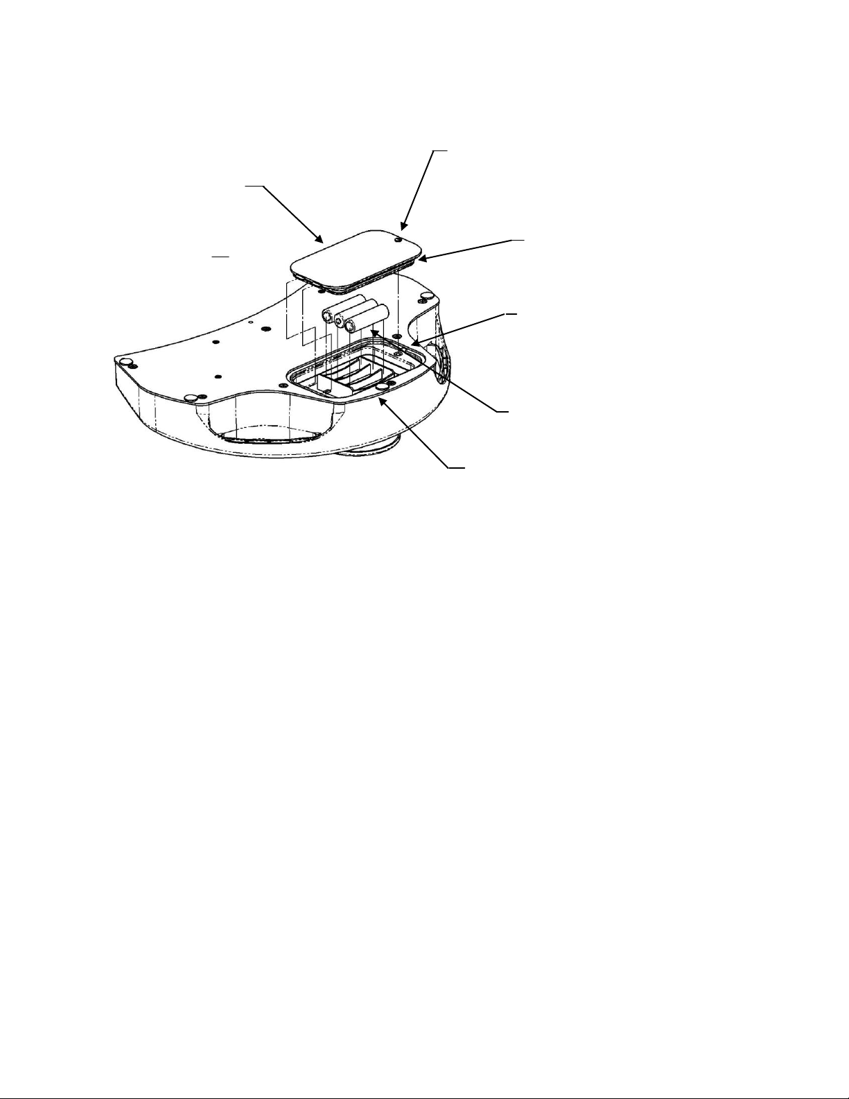
Couverture de la
pile
2x Languettes
Fermants
Entraînement
Rainureé ¼ -tour
agrafe
O-bague cachet
Encastré région pour
enlèvement du la couverture
(doudement faisant levier le
dispositif du la point plate
pour enlever la couverture)
3x piles “AA”
3x indicateur du polarité du la
pile sur visage de fond du
support.
Remplacement de la pile
Prudence Remplacez les piles dans le transmetteur avec haute qualité "AA" classent piles
alcalines comme montré. Jamais combiner fabricants quand remplacer les piles.
Jamais combiner piles vieilles et nouvelles. Le soin doit être pris quand remplacer
les piles pour ne pas endommager l'o-bague cachet sur l'abri de la pile. L'o-bague
cachet devrait être remplacé toutes les fois qu'il est endommagé ou son intégrité est
en question. Medtronic Advanced Energy recommande le cachet devrait être
remplacé au minimum chaque troisième fois les piles sont remplacées. Quand
remplacer le cachet le lubrifie avec gelée du pétrole.
Remplacez les piles dans le receveur avec haute qualité "C" classent piles alcalines
comme montré.
Fuite de la pile - Si le transmetteur ou receveur ne seront pas utilisés pour une
période étendue de temps, enlevez les piles pour prévenir le dégât dû à un possible
fuite de la pile.
Disposition de la pile - Suivez les recommandations du fabricant de la pile ou le
politique du votre hôpital pour la disposition de piles usagées.
Transmetteur
LBL-00098 Rev C
Page 32 of 257

Nettoyer
Les suivantes directives du nettoyage sont fournies.
PRUDENCES:
ABRASION- N'utilisez pas de tissu abrasif, d'objets tranchants, ou de nettoyeurs
abrasifs.
DÉCONNEXION- Détachez des câbles du l'interconnectez et l'adaptateur AC du
receveur.
IMMERSION- N'immergez pas le receveur, câbles ou connecteurs sous eau courante.
Transmetteur
Le transmetteur est estimé IP68 et peut être complètement immergé brièvement.
Mouillez un tissu non abrasif avec un des produits suivants; alors tordez dehors jusqu'à
légèrement mouillé et doucement le frottement a souillé la région jusqu'à propre.
Receveur
Alcool Isopropyl
Savon et eau
Cidex
Sodium Hypochlorite 5.25% (Blanchissant) dilué 10:1
PRUDENCE: Le receveur est estimé IPX et ne peut pas être immergé.
Mouillez un tissu non abrasif avec un des produits suivants; alors tordez dehors jusqu'à
légèrement mouillé et doucement le frottement a souillé la région jusqu'à propre.
Essuyez tous fluides de la surface du receveur.
Alcool Isopropyl
Savon et eau
Cidex
Sodium Hypochlorite 5.25% (Blanchissant) dilué 10:1
LBL-00098 Rev C
Page 33 of 257

Spécifications
Gamme: Typiquement 12.19m
Fonctions du interrupteur: Maximum de 5
État latent: Typiquement 200 millisecondes
Vie de la pile du transmetteur: 200 heures a 50% cycle du devoir typique
Consommation du pouvoir (transmetteur): Stand-by 100ua
Exigences du pouvoir (receveur): 6VDC a 200ma
Sortie du Receveur: SPST relaient, contacts de 0.5 ampères
360 degrés transmetteur
EN 60529 Degré de Protection IP68 (Transmetteur)
Certification
Classifié à IEC/UL 60601-1 matériel électrique Médical par les Underwriter's
Laboratoires, Inc. en ce qui concerne feu, choc, et hasards mécaniques conformément à
IEC/UL 60601-1.
Classifié en ce qui concerne choc électrique, feu, mécanique, et autres hasards spécifiés
seulement, conformément a CAN/CSA C22.2 No. 60601.1
EMC Normes
EN60601-1-2: 2001
IEC 1000-4-2: 1995 Immunité Électrostatique
IEC 1000-4-3: 1995 Immunité de Champ Électromagnétique Rayonnée a 10uv/m
IEC 1000-4-4: 1995 Immunité des Passage Électriques Rapides
IEC 1000-4-5: 1995 Immunité du Surtension
IEC 1000-4-6: 1996 Immunité du RF Menée
IEC 1000-4-8: 1993 Fréquence du Puissance Immunité de Champ Magnétique
IEC 1000-4-11: 1994 Plongements et Variations du Voltage
EN 55011: 1998 Émissions Rayonnés et Menées, Groupe 1 Classe B
FCC Part 15 Émissions Rayonnés et Menées, Class B
IEC 61000-3-2: 2000 Classe A Harmonies du Puissance
IEC 61000-3-3: 1995 + A1: 2001 Variation du Voltage, Section 5
Dimension
Transmetteur: 35.5cm x 25.4cm x 7.62cm
Receveur: 12.7cm x 8.89cm x 6.98cm
Poids
Transmetteur: 2.49kg avec piles
Receveur: 0. 204kg
LBL-00098 Rev C
Page 34 of 257

PULSAR® drahtloser Fußschalter
Bedienungsanleitung
LBL-00098 Rev C
Page 35 of 257

Sicherheit
Die Informationen in diesem Abschnitt sind wichtig für die Sicherheit von sowohl Patienten als
auch Bediener und sorgen ebenfalls für eine verbesserte Zuverlässigkeit des Gerätes. In diesem
Abschnitt wird beschrieben, wie die Begriffe Warnung, Achtung, Wichtig und Hinweis in dieser
Anleitung verwendet werden.
Allgemeine Informationen
Allgemeine Verwendung
Falls der Fußschalter sich kalt anfühlt oder seine Temperatur unter der
Umgebungstemperatur liegt, sollte sich das Gerät vor der Verwendung erst an die
Umgebungstemperatur anpassen.
Verwendung von ZUBEHÖRTEILEN, die nicht den Sicherheitsanforderungen
dieses Gerätes oder gleichwertigen Sicherheitsanforderungen entsprechen, kann
die Sicherheit des kombinierten Systems beeinträchtigen. Bei einer Auswahl der
Zubehörteile sollte Folgendes berücksichtigt werden:
- Verwendung des Zubehörteils in der NÄHE DES PATIENTEN
- Belege dafür, dass die Sicherheitszertifizierung des ZUBEHÖRTEILS
den entsprechenden harmonisierten nationalen Normen gemäß IEC 606011 und/oder IEC 60601-1-1 durchgeführt worden ist.
In regelmäßigen Abständen oder bei Zweifeln an der Unversehrtheit des Schalters
sollten alle Funktionen überprüft werden.
LBL-00098 Rev C
Page 36 of 257

Begriffserklärung
In dieser Anleitung werden vier Arten besonderer Hinweise verwendet: Warnung,
Achtung, Wichtig und Hinweis. Die Warnungen in diesem Abschnitt zur Sicherheit
beziehen sich auf das Gerät im Allgemeinen und gelten für alle Aspekte des Fußschalters.
Lesen Sie in jedem Fall die übrigen Abschnitte, da sie weitere Warnungen und Hinweise
zu spezifischen Funktionen des Fußschalters enthalten.
Warnung: Eine WARNUNG weist auf eine möglicherweise gefährliche
Situation hin, die zum Tod oder einer schwerwiegenden
Verletzung folgen könnte.
Achtung: ACHTUNGSHINWEISE weisen auf eine möglicherweise
gefährliche Situation hin, die zu einer leichten oder
mittelschweren Verletzung folgen könnte. Achtungshinweise
werden ebenfalls verwendet, um auf mögliche Beschädigung des
Gerätes hinzuweisen.
Wichtig: WICHTIG weist auf einen wichtigen Hinweis hin, um Ihre
Aufmerksamkeit auf einen bestimmten Aspekt zu leiten, der
möglicherweise nicht ohne weiteres sichtbar ist.
Hinweis: Ein HINWEIS lenkt Ihre Aufmerksamkeit auf bestimmte
Informationen.
Warnungen:
Plasma-Displays: Bei Verwendung von Plasma-Displays wurden starke
Betriebsbeeinträchtigungen von Infrarot-Geräten festgestellt.
Plasma-Geräte erhöhen die Schalterverzögerung erheblich oder
verhindern möglicherweise den Empfang des Signals vollständig.
Der drahtlose Pulsar Infrarot-Schalter sollte nicht in der
Nähe von Plasma-Displays verwendet werden.
Vor Verwendung des drahtlosen Infrarot-Fußschalters sollten Sie
sich von der Art des im Betriebsbereich verwendeten Displays
überzeugen. Plasma-Displays werden vom Hersteller auf der
Rückseite des Displays und/oder in der dazugehörigen
Bedienungsanleitung als solche identifiziert. Sollte die
Herstelleridentifikation auf der Rückseite des Displays nicht
sichtbar bzw. zugänglich und die Bedienungsanleitung nicht
griffbereit sein, erkundigen Sie sich bei Ihrer Abteilung für
Biomedizintechnik.
LBL-00098 Rev C
Page 37 of 257

Verschütten von Flüssigkeiten: Sollten Flüssigkeiten versehentlich auf den
Elektrischer Schlag: Um die Gefahr eines elektrischen Schlags zu vermeiden,
`
Warnungen:
Explosionsgefahr: Dieses Gerät nicht in der Nähe leicht entzündlicher Narkosemittel
Schnittstellen mit anderen Geräten:
Fußschalter müssen über Schnittstellen an andere Geräte
Achtungshinweise:
Jährliche Wartung: Um die andauernde Sicherheit und Leistung des Schalters
Tägliche Überprüfung: Es ist wichtig, dass der Fußschalter jeden Tag vor
Leistung: Das drahtlose Infrarot-Fußschaltersystem wird auf einer
Alle in Verbindung mit dem Fußschalter festgestellten Probleme
Verschreibungspflichtig: Laut US-Bundesgesetzen darf dieses Gerät in den
Empfänger verschüttet werden, sollte der Empfänger vor einer
weiteren Verwendung sorgfältig auf mögliche Schäden geprüft
werden.
sollten die Abdeckungen nicht entfernt werden. Die Wartung und
Reparatur des Gerätes sollte Fachleuten überlassen werden.
verwenden.
angeschlossen werden. Dabei sollten die Anweisungen der
Hersteller dieser Geräte für einen sicheren Betrieb befolgt
werden.
zu gewährleisten, sollten die Funktionsfähigkeit und die
elektrische Sicherheit des Schalters jährlich überprüft werden.
Inbetriebnahme überprüft wird.
Wellenlänge von 870 nm betrieben. Es sollte getestet werden, ob
der Schalter mit anderen Geräten, an die es angeschlossen ist oder
in deren Umgebung es verwendet wird, kompatibel ist.
sollten gemeldet werden. Falls der Fußschalter nicht
ordnungsgemäß funktioniert, wenden Sie sich an den
Wartungsdienst. Ein nicht ordnungsgemäß funktionierender
Fußschalter sollte nicht verwendet werden.
Vereinigten Staaten nur an Ärzte oder auf ärztliche Anweisung
verkauft werden.
LBL-00098 Rev C
Page 38 of 257

Elektromagnetische Störungen
Dieses Gerät wurde getestet und die Einhaltung der Grenzwerte für
Medizinprodukte entsprechend der Norm EN 60601-1-2 (2002),
Richtlinie 93/42/EWG über Medizinprodukte bestätigt. Diese
Grenzwerte dienen dem angemessenen Schutz vor schädlichen
Störungen in einer typischen medizinischen Einrichtung.
Aufgrund der starken Zunahme von auf Radiofrequenzen
übertragenden Geräten und anderen Quellen elektrischer Störungen
in Einrichtungen des Gesundheitswesens und in Privathäusern ist
es möglich, dass die Nähe oder Stärke einer derartigen Quelle zu
hohen Störungsniveaus führt, die die Leistung dieses Gerätes
beeinträchtigen können.
Dieses Gerät erzeugt, verwendet und gibt Hochfrequenzenergie ab
und kann, falls es nicht diesen Anweisungen entsprechend
installiert und verwendet wird, schädigende Störungen von anderen
in der Nähe befindlichen Geräten verursachen. Diese Störungen
können sich in einem unregelmäßigen oder nicht
ordnungsgemäßen Betrieb äußern. In einem solchen Fall sollte der
Standort zur Identifikation der Störungsquelle untersucht und
geeignete Maßnahmen zur Behebung der Störungen ergriffen
werden.
Dabei sollte der Anwender eine Behebung der Störung zuerst mit
einer der folgenden Maßnahmen versuchen:
Geräte in der Umgebung einzeln aus- und einschalten, um
das die Störung verursachende Gerät zu identifizieren.
Das andere Empfangsgerät neu ausrichten oder an einem
anderen Ort aufstellen.
Den Abstand zwischen dem störenden Gerät und diesem
Gerät vergrößern.
Sollten Sie Unterstützung benötigen, setzen Sie sich mit
Ihrem Ansprechpartner bei Medtronic Advanced Energy in
Verbindung.
LBL-00098 Rev C
Page 39 of 257

ACHTUNG: Lesen Sie die beigefügten Informationen durch!
l
Ein-schalter
Batterie fast leer
Gebrauchsanweisung beachten.
Herstellungsdatum
Sondermüllentsorgung entsprechend den europäischen Richtlinien und
den geltenden nationalen, regionalen und kommunalen Vorschriften.
Hersteller
Gerätesymbole
Die folgende Liste enthält die Symbole, die auf dem Produkt verwendet werden.
Tabelle 1-2. Gerätesymbole
LBL-00098 Rev C
Page 40 of 257

XXX
Beispiel A
Der Buchstabe zeigt an, ob es sich um
einen Sender oder einen Empfänger
Die letzte Ziffer
bezeichnen den Kanal.
Kanal/Kodierung
Der Infrarot-Fußschalter kann auf vier verschiedene Kanäle eingestellt werden. Das heißt, dass
bis zu vier verschiedene Schalter gleichzeitig im selben Bereich verwendet werden können. Der
eingestellte Kanal lässt sich anhand der Seriennummer des jeweiligen Gerätes identifizieren.
(siehe Beispiel unten). Der Kanal wird ebenfalls auf dem Etikett auf der Oberseite der Geräte
angezeigt.
XXXXXXXX T001
Zusätzlich zu den vier Kanälen verwendet jeder Hersteller seine eigene Verschlüsselung.
Dadurch wird gewährleistet, dass Hersteller, deren Geräte denselben Kanal benutzen,
gleichzeitig im selben Bereich eingesetzt werden können, ohne dass sich die Geräte gegenseitig
stören. Der Herstellercode ist, wie unten abgebildet, in die Modellnummer integriert. Er wird
ebenfalls auf dem Etikett auf der Oberseite der Geräte angezeigt.
Geräteetikett:
Die ersten zwei oder drei Ziffern sind der Herstellercode, die letzte Ziffer der Kanal.
SP-9970214-XXX XXXXXX
Diese drei Ziffern sind der Herstellercode.
LBL-00098 Rev C
Page 41 of 257

A
B
C
Name
Beschreibung
A
Stromanzeige
Wird das Gerät mit Strom versorgt, leuchtet die
Stromanzeige grün.
B
Funktionsanzeigen 1-5
Die LEDs leuchten auf, wenn Schalter betätigt werden.
C
Batterieanzeige
des
Fußschalters
Ist die Batterie fast leer, fängt die rote LED zu blinken
an. Die LED blinkt 3-4 Stunden lang. Sobald sie
ununterbrochen leuchtet, ist noch Energie für etwa 3-4
Stunden vorhanden. Die Batterien sollten jedoch
umgehend ausgetauscht werden.
D
IR-Schlüssel
Dieses Etikett zeigt den Herstellercode und den vom
Empfänger für die Kommunikation mit einem
Fußschalter verwendeten Kanal an. Dieses Etikett ist
farblich kodiert; der Fußschalter ist mit einem
identischen Etikett versehen (Seite 44). Auf Seite 41
finden Sie Details zur Kanalkodierung.
XXX
D
Vorderansicht des Empfängers
LBL-00098 Rev C
Page 42 of 257

Beschreibung
J5
Ausgangsanschluss: Für den Anschluss des Schnittstellenkabels am Gerät des
Benutzers.
Hinteransicht des Empfängers
LBL-00098 Rev C
Page 43 of 257

Beschreibung
A
Hauptschalter
Einzel- oder Doppelfunktion
B
IR-Schlüssel. Dieses Etikett zeigt den
Herstellercode und den vom Empfänger für die
Kommunikation mit einem Fußschalter
verwendeten Kanal an. Dieses Etikett ist
farblich kodiert; der Empfänger ist mit einem
identischen Etikett versehen (Seite 42). Auf
Seite 41 finden Sie Details zur Kanalkodierung.
A
B
Sender
LBL-00098 Rev C
Page 44 of 257
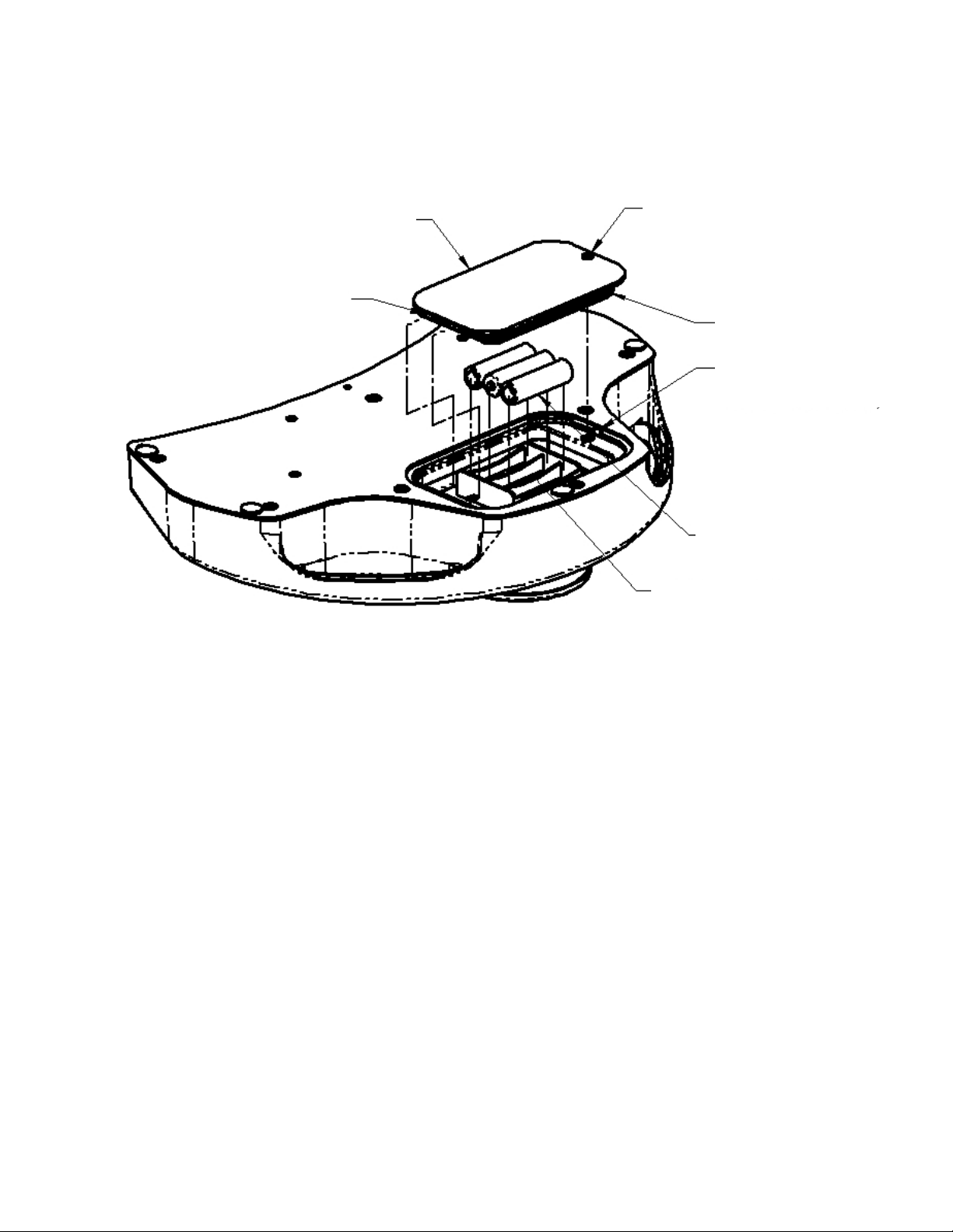
Schraubenloch
1/4-Drehung
O-Ringdichtung
vertiefter Bereich zum Entfernen
der Abdeckung (flaches Ende
dazu vorsichtig anheben)
3 Polaritätsanzeiger auf dem Boden des
Batteriefachs
3 Mignon-Batterien
Batterieabdeckung
2 Sperrriegel
Auswechseln der Batterien
Sender
Achtung Für den Sender sollten nur hochwertige Mignon-Alkalibatterien (AA) wie
abgebildet verwendet werden. Beim Auswechseln der Batterien sollten niemals
Batterien verschiedener Hersteller und niemals alte und neue Batterien zusammen
verwendet werden. Seien Sie beim Batteriewechsel vorsichtig, um nicht die ORingdichtung an der Batterieabdeckung zu beschädigen. Die O-Ringdichtung sollte
ausgetauscht werden, wenn sie beschädigt ist oder eine Beschädigung vermutet
wird. Den Empfehlungen von Medtronic Advanced Energy entsprechend sollte die
Dichtung mindestens bei jedem dritten Batteriewechsel ausgetauscht werden. Beim
Auswechseln der Dichtung sollte diese mit Rohvaseline geschmiert werden.
Auslaufen der Batterien: Falls der Sender für einen längeren Zeitraum nicht
verwendet wird, sollten die Batterien entfernt werden, um eine Beschädigung durch
eventuelles Auslaufen zu vermeiden.
Entsorgung der Batterien: Die Batterien sollten den Empfehlungen des Herstellers
bzw. den Richtlinien der Einrichtung bezüglich verbrauchter Batterien
entsprechend entsorgt werden.
LBL-00098 Rev C
Page 45 of 257

Reinigung
Die folgenden Reinigungsanweisungen sind zu beachten.
ACHTUNGSHINWEISE:
ABRIEB: Aggressive oder scheuernde Reinigungsmittel, Scheuerkissen und scharfe
Objekte sollten nicht verwendet werden.
TRENNUNG VOM STROMNETZ: Trennen Sie die Verbindungskabel vom
Empfänger.
EINTAUCHEN IN FLÜSSIGKEITEN: Empfänger, Kabel und Anschlüsse nicht
unter laufendes Wasser halten.
Sender
Der Sender ist als IP68 klassifiziert und darf kurz vollständig eingetaucht werden.
Ein nicht scheuerndes Tuch mit einem der folgenden Produkte anfeuchten, auswringen,
bis es nur noch leicht feucht ist, und verschmutzte Bereiche unter leichtem Reiben
säubern.
Isopropylalkohol
Wasser und Seife
Cidex
5.2% Natriumhypochlorit (Bleiche) in einer Verdünnung von 10:1
Empfänger
ACHTUNG: Der Empfänger ist als IPX1 klassifiziert und darf nicht eingetaucht werden.
Ein nicht scheuerndes Tuch mit einem der folgenden Produkte anfeuchten, auswringen,
bis es nur noch leicht feucht ist, und verschmutzte Bereiche unter leichtem Reiben
säubern.
Alle Flüssigkeiten von der Oberfläche des Empfängers abwischen.
Isopropylalkohol
Wasser und Seife
Cidex
5.2% Natriumhypochlorit (Bleichmittel) in einer Verdünnung von 10:1
LBL-00098 Rev C
Page 46 of 257

Spezifikationen
Reichweite: normalerweise 12.19m
Schalterfunktionen: maximal 5
Verzögerung: normalerweise 200 ms
Lebensdauer der Senderbatterien: 200 Stunden bei 50%-iger Auslastung
Stromverbrauch (Sender): Standby 100 uA
Leistungsbedarf (Empfänger): 6 V DC bei 200 mA
Ausgang des Empfängers: einpoliges Einschaltrelais, 0,5 A Kontakte
360-Grad-Sender
EN 60529, Schutzart IP68 (Sender)
Zertifizierung
Klassifiziert bezüglich Feuer, elektrischer Schlag und mechanische Gefahren gemäß
IEC/UL 60601-1 für elektrische Medizingeräte durch Underwriter's Laboratories, Inc.
Klassifiziert nur bezüglich elektrischer Schlag, mechanischer und anderer spezifischer
Gefahren gemäß CAN/CSA C22.2 Nr. 60601.1
EMV-Standards
EN60601-1-2: 2001
IEC 1000-4-2: 1995 Störsicherheit gegen elektrostatische Entladung
IEC 1000-4-3: 1995 Störsicherheit gegen hochfrequente elektromagnetische Felder bei
10 uV/m
IEC 1000-4-4: 1995 Störsicherheit gegen schnelle Transiente
IEC 1000-4-5: 1995 Störfestigkeit gegen Stoßspannungen
IEC 1000-4-6: 1996 Störfestigkeit gegen hochfrequente eingespeiste Ströme
IEC 1000-4-8: 1993 Störfestigkeit gegen Magnetfelder mit energietechnischer Frequenz
IEC 1000-4-11: 1994 Spannungsschwankungen und -unterbrechungen
EN 55011 1998 Störaussendung, Gruppe 1, Klasse B
FCC Teil 15 Störaussendungen, Klasse B
IEC 61000-3-2: 2000 Oberschwingungsströme Klasse A
IEC 61000-3-3: 1995 + A1: 2001 Spannungsschwankungen, Abschnitt 5
Abmessungen
Sender: 35.5cm x 25.4cm x 7.62cm
Empfänger: 12.7cm x 8.89cm x 6.98cm
Gewicht
Sender: 2.49 kg mit Batterien
Empfänger: 0,204 kg
LBL-00098 Rev C
Page 47 of 257

Interruttore a pedale senza fili PULSAR®
Manuale dell’operatore
LBL-00098 Rev C
Page 48 of 257

Sicurezza
Le informazioni presentate in questo paragrafo sono importanti per la sicurezza sia del paziente
che dell’operatore e servono anche a migliorare l'affidabilità dell'apparecchiatura. Questo
paragrafo spiega il significato dei termini Avvertenza, Attenzione, Importante e Nota bene,
utilizzati nel manuale.
Dati generali
Utilizzo generale
Se l’interruttore a pedale è freddo al tatto o sotto la temperatura ambiente,
lasciarlo stabilizzare prima dell’uso.
L’abbinamento con ACCESSORI non conformi ai requisiti di sicurezza adottati in
questa apparecchiatura può inficiare la sicurezza del complesso risultante. Nel
considerare tale scelta, tenere presenti:
- l’utilizzo dell’accessorio in VICINANZA DEL PAZIENTE
- prova dell’effettuazione della certificazione di sicurezza
dell’ACCESSORIO in conformità agli standard nazionali armonizzati
IEC 60601-1 o IEC 60601-1 adeguati.
Ogni volta che si nutrono dubbi sull’integrità dell’interruttore, si raccomanda di
mettere alla prova periodicamente tutte le funzioni.
LBL-00098 Rev C
Page 49 of 257

Definizioni di terminologia
In questo manuale si utilizzano quattro tipi di avviso speciale. Essi sono: Avvertenza,
Attenzione, Importante e Nota bene. I segnali di avvertenza e di attenzione in questo
paragrafo sulla sicurezza si riferiscono alle apparecchiature prese in generale e a tutti gli
aspetti dell'interruttore a pedale. Si raccomanda la lettura degli altri capitoli, perché vi sono
altre indicazioni di avvertenza e di attenzione che si riferiscono a specifiche caratteristiche
dell’interruttore a pedale.
Avvertenza- La dicitura AVVERTENZA indica una situazione pericolosa, che
se non evitata, può risultare letale o recare gravi lesioni.
Attenzione- La dicitura ATTENZIONE indica una situazione pericolosa, che
se non evitata, può recare lesioni di entità da minima a modesta.
Tale dicitura serve anche per evitare il danneggiamento
dell’apparecchiatura.
Importante- L’avviso IMPORTANTE indica una nota con risalto. È qualcosa
di cui bisognerebbe essere particolarmente consapevoli, qualcosa
non prontamente manifesto.
Nota bene- NOTA BENE indica un’informazione particolare, qualcosa su cui
appuntare l’attenzione.
Avvisi:
Schermi al plasma- Si è osservato che gli schermi video al plasma influenzano
seriamente il funzionamento delle apparecchiature all’infrarosso.
Gli apparecchi al plasma aumentano notevolmente la latenza
dell’interruttore o bloccano del tutto la ricezione del segnale.
Evitare l'impiego dell'interruttore a pedale all'infrarosso
senza fili Pulsar in vicinanza degli schermi video al plasma.
Verificare quali schermi sono presenti nell’area di funzionamento
prima di utilizzare l’interruttore a pedale all’infrarosso senza fili.
Gli schermi al plasma si riconoscono dall'indicazione del
fabbricante sul retro dello schermo e/o nel manuale
dell’operatore. Se la targhetta d’identificazione non è in vista sul
retro dello schermo o il manuale dell’operatore non è disponibile,
rivolgersi al reparto d’ingegneria biomedica per assistenza
nell’identificazione.
Versamenti Nel caso di versamento accidentale di liquidi sul ricevitore,
accidentali- disattivarlo ed esaminarlo alla ricerca di guasti.
LBL-00098 Rev C
Page 50 of 257

Scossa elettrica- Per ridurre il rischio di scosse elettriche, lasciare in sede le
coperture. Per gli interventi rivolgersi al personale qualificato.
Avvisi:
Rischio Non utilizzare questa apparecchiatura in presenza di anestetici
d’esplosione- infiammabili.
Interfaccia con- Gli interruttori a pedale devono essere collegati ad altre
apparecchiatura apparecchiature. Per un funzionamento in tutta sicurezza occorre
consultare le specifiche del fabbricante.
Attenzione:
Manutenzione Per garantire un funzionamento sicuro ed efficiente
annuale- dell’interruttore, si raccomanda di verificarne il funzionamento e
la sicurezza elettrica su base annua.
Collaudo È essenziale che l’interruttore a pedale sia ispezionato ogni giorno
quotidiano- o prima dell’uso.
Prestazioni- L’impianto dell’interruttore a pedale senza fili all’infrarosso
funziona su una lunghezza d’onda di 870 nm. Per verificarne la
compatibilità con un’apparecchiatura a cui di desidera collegarlo
o con un ambiente di lavoro, occorre metterlo alla prova.
Prendere nota di tutti i problemi riscontrati. Se l’interruttore non
funziona correttamente, rivolgersi al tecnico dell’assistenza di
zona. Se l’interruttore non funziona correttamente, non deve
essere messo all’opera.
Solo per medici- Negli Stati Uniti d’America, la legge federale consente la vendita
di questo apparecchio solo da parte di un medico o su sua
richiesta.
LBL-00098 Rev C
Page 51 of 257

Interferenza elettromagnetica
Questo apparecchio è stato collaudato e riscontrato conforme ai
requisiti sui limiti per le apparecchiature mediche EN 60601-1-2
(2002) e la direttiva sulle apparecchiature mediche 93/42/CEE.
Questi limiti sono studiati per fornire un ragionevole grado di
protezione contro le interferenze nocive in una tipica installazione
medica.
Tuttavia, a causa del proliferare delle apparecchiature che
trasmettono in frequenza radio e di altre sorgenti di disturbo
elettriche in ambiente sanitario e domestico, è possibile che alti
livelli di tale interferenza dovuti a stretta vicinanza o intensità di
una sorgente, causino dei cali nel rendimento di questo
apparecchio.
Questo strumento genera, utilizza e talora irradia energia di
frequenza radio e se non installato e utilizzato in conformità a
queste istruzioni, può causare interferenze dannose ad altre
apparecchiature nelle vicinanze. Discontinuità o interferenza sono
riconoscibili dal funzionamento imprevedibile o impreciso. In tal
caso ispezionare la postazione di lavoro per individuare la sorgente
di questa discontinuità e prendere le misure necessarie per
eliminarla.
L’utente può tentare di rimediare all’interferenza nei seguenti
modi:
Accendere e spegnere a turno tutte le apparecchiature nelle
immediate vicinanze per individuare quella responsabile.
Riorientare o riposizionare l’altro strumento ricevente.
Aumentare la distanza tra l’apparecchio interferente e
questo strumento.
Se occorre assistenza, rivolgersi al rappresentante
Medtronic Advanced Energy di zona.
LBL-00098 Rev C
Page 52 of 257

ATTENZIONE: vedere i documenti a corredo
l
Accensione
Batteria in esaurimento
Seguire le istruzioni per l’uso
Data di produzione
Raccolta differenziata degli scarti alla fine della vita utile ai sensi delle
direttive europee. Smaltire in conformità alla normativa vigente nel
paese.
Fabbricante
Simboli dell’apparecchiatura
Di seguito viene indicato un elenco di simboli usati sul prodotto.
Tavola 1-2. Simboli delle apparecchiature
LBL-00098 Rev C
Page 53 of 257

XXX
Esempio A
La cifra iniziale designa il trasmettitore o il
ricevitore
L’ultima cifra designa il
canale
Canale/codifica
L’interruttore a pedale ha quattro diverse capacità di canale. Questo permette di utilizzare fino a
quattro interruttori diversi nella stessa area simultaneamente. Il canale s’identifica nel numero di
serie delle unità. Vedere l’esempio sotto. Il canale figura anche su un’etichetta in cima alle unità.
XXXXXXXX T001
Oltre ai quattro canali ogni fabbricante ha la propria crittografia codificata. In questo modo si
assicura che nella stessa area siano utilizzabili simultaneamente senza interferenze diversi
fabbricanti con il medesimo contrassegno di canale. Il codice del fabbricante è incluso nel
numero di modello come mostrato sotto. Figura anche su un’etichetta in cima alle unità.
SP-9970214-XXX XXXXXX
Queste tre cifre indicano il codice fabbricante.
Etichetta dell’unità:
Le prime due o tre lettere denotano il codice del fabbricante, l’ultima cifra è il canale.
LBL-00098 Rev C
Page 54 of 257

A
B
C
Nome
Descrizione
A
Spia di
accensione.
La spia di accensione verde indica che l’unità è
accesa.
B
Spie di
funzionamen
to
interruttore
da 1 a 5
I LED si accendono quando vengono azionati gli
interruttori.
C
Indicatore di
batteria in
esaurimento
interruttore a
pedale
Il LED rosso lampeggia quando le batterie sono
vicine al termine della vita utile. Il LED lampeggia
per 3-4 ore. Quando il LED sta acceso senza
soluzione di continuità vi sono ancora 3-4 ore di
durata di batteria. Tuttavia le batterie devono
essere sostituite seduta stante.
D
Etichetta
chiave IR
Questa etichetta indica il codice e canale del
fabbricante, che la ricevente usa per abbinamento
all'interruttore a pedale. Questa etichetta ha un
codice colore e l’interruttore a pedale ha
un’etichetta identica (pag 56). Si rinvia a pag 54
per i dettagli della codifica canale.
XXX
D
Vista frontale del ricevitore
LBL-00098 Rev C
Page 55 of 257

Descrizione
J5
Connettore dell’uscita: per collegamento del cavo d’interfaccia
all’apparecchiatura dell’utente.
Vista posteriore del ricevitore
LBL-00098 Rev C
Page 56 of 257

Descrizione
A
Interruttori principali
Funzione singola o doppia
B
Etichetta chiave IR. Questa etichetta indica il
codice e canale del fabbricante, che il ricevitore
usa per abbinamento all'interruttore a pedale.
Questa etichetta ha un codice colore e
l’interruttore a pedale ha un’etichetta identica
(pag 55). Si rinvia a pag 54 per i dettagli della
codifica canale.
A
B B
Trasmettitore
LBL-00098 Rev C
Page 57 of 257

COPERCHIO BATTERIA
CHIUSURA CON 1/4 DI GIRO
INCASTRO A FESSURA
2 LINGUETTE DI ARRESTO
GUARNIZIONE AD ANELLO
TACCA PER APERTURA
COPERCHIO (FARE LEVA
DELICATAMENTE CON UTENSILE
PIATTO PER STACCARE IL
COPERCHIO)
3 BATTERIE “AA”
INDICATORE POLARITÀ
BATTERIE (3) SUL FONDO DEL
CONTENITORE
Sostituzione della batteria
trasmettitore
Attenzione Sostituire le batterie del trasmettitore con quelle alcaline di alta qualità di
dimensione “AA” come mostrato. Non mescolare mai batterie di marca diversa.
Non mescolare mai batterie vecchie e nuove. Nella sostituzione delle batterie
prestare attenzione a non danneggiare l’anello di tenuta sul coperchio batterie.
L’anello di tenuta deve essere sostituito ogni volta che viene danneggiato o
comunque l’integrità ne sembra compromessa. Medtronic Advanced Energy ne
raccomanda la sostituzione almeno una volta ogni tre sostituzioni delle batterie.
Quando si sostituisce il sigillo, lubrificare con vaselina.
Perdita dalle batterie- Se il trasmettitore non viene utilizzato per un lungo periodo,
rimuovere le batterie per evitare danneggiamenti da eventuale perdita dalle batterie.
Smaltimento delle batterie- Seguire le raccomandazioni del fabbricante o il
regolamento del proprio ospedale per l’eliminazione delle batterie esaurite.
LBL-00098 Rev C
Page 58 of 257

Pulizia
Vengono fornite le seguenti istruzioni per le pulizie.
ATTENZIONE:
ABRASIONE - Evitare di utilizzare panni abrasivi, oggetti taglienti, o detersivi abrasivi.
SCOLLEGAMENTO – Staccare i cavi di collegamento dal ricevitore.
IMMERSIONE - Evitare di immergere il ricevitore, i cavi o i connettori in acqua
Trasmettitore
Il trasmettitore è classificato IP68 e può essere immerso completamente per breve tempo.
Inumidire un panno soffice con uno dei seguenti detergenti, quindi strizzarne l'eccesso e
strofinare delicatamente l'area sporca finché pulita.
Ricevitore
corrente.
Alcol isopropilico
Acqua e sapone
Cidex
Ipoclorito di sodio al 5,25% (candeggina) diluito 10:1
ATTENZIONE: il ricevitore è classificato IPX1 e non può essere immerso.
Inumidire un panno soffice con uno dei seguenti detergenti, quindi strizzarne l'eccesso e
strofinare delicatamente l'area sporca finché pulita.
Asciugare con un panno eventuali liquidi dalla superficie del ricevitore.
Alcol isopropilico
Acqua e sapone
Cidex
Ipoclorito di sodio al 5,25% (candeggina) diluito 10:1
LBL-00098 Rev C
Page 59 of 257

Specifiche
Raggio d’azione: generalmente 12.19m
Funzioni interruttore: 5 al massimo
Latenza: generalmente 200 millisecondi
Durata della batteria del trasmettitore: generalmente 200 ore con ciclo al 50%
Consumo di energia (trasmettitore): in stand-by 100 ua
Corrente richiesta (ricevitore): 6 V CC @ 200 ma
Uscita del ricevitore: relè SPST, contatti a 0,5 amp
trasmettitore a 360 gradi
Grado di protezione EN 60529 IP68 (trasmettitore)
Certificazione
Classificato secondo IEC/UL 60601-1 apparecchiatura medica elettrica di Underwriter’s
Laboratories, Inc per quanto riguarda i rischi d’incendio, di scossa e meccanici come
previsto in IEC/UL 60601-1.
Classificato in conformità a CAN/CSA C22.2 No. 60601.1 riguardo solo a rischi di
scosse elettriche, d’incendio, meccanici e altri specificati.
Standard EMC
EN60601-1-2: 2001
IEC 1000-4-2: 1995 esente da carica elettrostatica
IEC 1000-4-3: 1995 esenzione da campo elettromagnetico irradiato a 10uv/m
IEC 1000-4-4: 1995 esenzione da correnti transitorie rapide
IEC 1000-4-5: 1995 esenzione da sovracorrente
IEC 1000-4-6: 1996 esenzione da frequenza radio di conduzione
IEC 1000-4-8: 1993 esenzione da campo magnetico di frequenza di corrente
IEC 1000-4-11: 1994 cali improvvisi e variazioni di tensione
EN 55011: 1998 emissioni da irradiazione e da conduzione, gruppo 1, classe B
FCC parte 15 emissioni da irradiazione e conduzione, classe B
IEC 61000-3-2: 2000 armoniche di potenza classe A
IEC 61000-3-3: 1995 + A1: 2001 oscillazione di tensione, sezione 5
Ingombro
Trasmettitore: 35.5cm x 25.4cm x 7.62cm
Ricevitore: 12.7cm x 8.89cm x 6.98cm
Peso
Trasmettitore: 2.49kg con batterie
Ricevitore: 0.204kg
LBL-00098 Rev C
Page 60 of 257

Interruptor de pie inalámbrico PULSAR®
Manual del Operador
LBL-00098 Rev C
Page 61 of 257

Seguridad
La información presentada en esta sección es importante para la seguridad tanto del paciente
como del operador y sirve también para mejorar la fiabilidad del equipo. La presente sección
describe cómo se utilizan a lo largo del manual los términos Advertencia, Precaución, Importante
y Nota.
Información general
Uso general
Si el interruptor de pie está frío al tacto o se encuentra por debajo de la
temperatura ambiente, déjelo estabilizarse antes de utilizarlo.
El uso de equipos AUXILIARES no compatibles con los requisitos equivalentes
de seguridad del presente equipo puede ocasionar una menor seguridad del
sistema resultante. Las consideraciones relativas a la elección incluirán:
-uso del accesorio en las PROXIMIDADES DEL PACIENTE
-prueba de que la certificación de seguridad del ACCESORIO se ha
realizado de conformidad con las oportunas normas nacionales IEC
60601-1 y/o IEC-60601-1-1 armonizadas.
Con carácter periódico, cuando se dude de la integridad del interruptor,
comprobar todas las funciones.
LBL-00098 Rev C
Page 62 of 257

Definiciones y Terminología
Se utilizan en el presente manual cuatro tipos de avisos especiales. Son: Advertencia,
Precaución, Importante y Nota. Las advertencias y las precauciones de la presente sección
sobre seguridad hacen referencia al equipo de forma general y se aplican a todos los
aspectos del interruptor de pie. Cerciórese de leer los demás capítulos, ya que existen
advertencias y precauciones adicionales que hacen referencia a características específicas
del interruptor de pie.
Advertencia- Una ADVERTENCIA indica una situación de posible peligro,
que de no evitarse, podría ocasionar la muerte o lesiones graves.
Precaución- Una PRECAUCIÓN indica una situación de posible peligro, que
de no evitarse, podría ocasionar lesiones leves o moderadas. Las
precauciones se emplean también para evitar daños al equipo.
Importante- Un aviso IMPORTANTE indica una nota sobre la que se hace
hincapié. Es algo de lo que debería tomarse especial nota, algo
que no es aparente a simple vista.
Nota- Una NOTA indica un punto concreto de información algo en lo
que centrar la atención.
Advertencias:
Pantallas de Plasma- Se ha observado que las pantallas de plasma afectan gravemente
al funcionamiento de los dispositivos infrarrojos. Los dispositivos
de plasma aumentarán de forma significativa la latencia del
interruptor y evitan totalmente la recepción de la señal.
No utilizar el interruptor de pie inalámbrico Pulsar cerca de
pantallas de vídeo de plasma.
Confirme qué tipo de pantallas hay en la zona de funcionamiento
antes de emplear el interruptor de pie inalámbrico por infrarrojos.
Las pantallas de plasma se identifican como tales por parte del
fabricante en la parte trasera de las mismas y/o en el manual del
operador. Si no es visible la identificación del fabricante en la
parte trasera de la pantalla o no se dispone fácilmente del manual
del operador, póngase en contacto con su Departamento de
Ingeniería Biomédica para solicitar ayuda en la identificación.
Vertidos accidentales- En caso de que se viertan accidentalmente líquidos sobre el
receptor, póngalo fuera de servicio e inspeccione si hay daños.
Descarga eléctrica- Para reducir el riesgo de descarga eléctrica no quite ninguna tapa.
Deje el mantenimiento en manos de personal cualificado.
LBL-00098 Rev C
Page 63 of 257

`
Advertencias:
Peligro de explosión- No utilice el equipo en presencia de anestésicos inflamables.
Interacción con- Los interruptores de pie deben interactuar con otro equipo.
Equipos Cerciórese de consultar las especificaciones del fabricante para
mantener un funcionamiento seguro.
Precauciones:
Mantenimiento anual- Para un rendimiento seguro y continuado del interruptor, se
recomienda que se verifique con periodicidad anual la
funcionalidad y la seguridad eléctrica del mismo.
Comprobación diaria- Es esencial que se inspeccione cada día el interruptor de pie antes
de usarlo.
Rendimiento- El sistema infrarrojo inalámbrico del interruptor de pie funciona
en una longitud de onda de 870 nm. Debería comprobarse para
asegurar la compatibilidad con cualquier dispositivo al que se
conecte o cualquier entorno en el que funcione.
Informe de todos los problemas sufridos con el interruptor de pie.
Si el interruptor de pie no funciona adecuadamente, póngase en
contacto con su representante del servicio técnico para que lo
repare. No debería utilizarse el interruptor de pie si no funciona
adecuadamente.
Solo Rx- En los Estados Unidos de América la ley federal restringe el
dispositivo a su venta por parte de un médico o bajo pedido del
mismo.
LBL-00098 Rev C
Page 64 of 257

Interferencia Electromagnética
Este dispositivo ha sido comprobado y hallado conforme con los
límites para dispositivos médicos de la norma EN 60601-1-2
(2002), Directiva de Productos Sanitarios 93/42/CEE. Estos límites
están diseñados para proporcionar un grado de protección
razonable contra interferencias perjudiciales en una instalación
médica típica.
No obstante, dada la proliferación de equipos transmisores de
radiofrecuencia y otras fuentes de ruido eléctrico en entornos
sanitarios y residenciales, es posible que los elevados niveles de
tales interferencias debidos a la cercanía o la potencia de una
fuente emisora puedan ocasionar perturbaciones en el rendimiento
de este dispositivo.
Este equipo genera, usa y puede irradiar energía de radiofrecuencia
y, si no se instala y utiliza conforme a las presentes instrucciones,
puede provocar interferencias perjudiciales con otros dispositivos
cercanos. Pueden evidenciarse perturbaciones o interferencias por
un funcionamiento errático o incorrecto. Si ello ocurre, debería
inspeccionarse el lugar de funcionamiento a fin de establecer la
fuente de tal perturbación y adoptarse medidas para eliminar la
fuente.
Se aconseja al usuario intentar corregir la interferencia mediante
una de las siguientes medidas:
Apagar y encender los equipos cercanos para aislar el
dispositivo que causa las perturbaciones.
Reorientar o cambiar de lugar el otro dispositivo receptor.
Aumentar la separación entre el equipo que causa las
interferencias y este equipo.
Si se precisa asistencia, póngase en contacto con su
Representante de Medtronic Advanced Energy.
LBL-00098 Rev C
Page 65 of 257

ATENCIÓN: Consultar documentos adjuntos
l
Encendido
Batería baja
Siga las instrucciones de uso.
Fecha de fabricación
Recogida separada de residuos al final de la vida útil según lo exigido
por las directivas europeas. Desechar de conformidad con la legislación
vigente del país.
Fabricante
Símbolos del Equipo
A continuación se facilita una lista de símbolos utilizados en el producto.
Tabla 1-2. Símbolos del Equipo
LBL-00098 Rev C
Page 66 of 257

Ejemplo A
El dígito alfabético designa transmisor o
receptor
El último dígito designa
el canal
XXX
Canal/Codificación
El interruptor de pie por infrarrojos dispone de cuatro funcionalidades de canal diferentes. Ello
permite el uso de hasta cuatro interruptores diferentes en la misma zona de forma simultánea. El
canal se identifica en el número de serie de las unidades. Ver el ejemplo mostrado más abajo. El
canal aparece también en una etiqueta colocada en la parte superior de las unidades.
XXXXXXXX T001
Además de los cuatro canales, cada fabricante dispone de su propia encriptación de códigos. Ello
garantiza que diferentes fabricantes con idénticas marcas de canal puedan ser utilizados en la
misma zona de forma simultánea sin interferencias. El código del fabricante se encuentra
incluido el número de modelo, tal y como se muestra más abajo. Aparece también en una
etiqueta colocada en la parte superior de las unidades.
Etiqueta de la unidad:
Los dos o tres primeros dígitos denotan el código del fabricante; el último dígito es el canal.
SP-9970214-XXX XXXXXX
Estos tres dígitos denotan el código del fabricante
LBL-00098 Rev C
Page 67 of 257

A
B
C
Nombre
Descripción
A
Indicador de
encendido
El indicador de encendido se ilumina en verde para indicar
que la unidad está encendida.
B
Indicadores 1-5
de función del
interruptor
Los LED se iluminarán cuando se accionen los interruptores.
C
Indicador de
batería baja del
interruptor de
pie
Parpadeará el LED rojo cuando las pilas estén próximas a
agotarse. El LED parpadeará durante 3-4 horas. Cuando el
LED se quede constantemente encendido, quedarán 3-4 horas
de vida de las pila. No obstante, deberían sustituirse las pilas
de inmediato.
D
Etiqueta de
Clave de IR
Esta etiqueta indica el código del fabricante y el
canal empleado por el receptor para emparejarse
con el interruptor de pie. Esta etiqueta tiene un
código de colores y el interruptor de pie dispone de
otra etiqueta idéntica (página 69). Consulte la
página 67 para obtener detalles de la codificación
de canales.
XXX
D
Parte frontal del receptor
LBL-00098 Rev C
Page 68 of 257

Descripción
J5
Conector de salida: Para conectar el cable de interfaz con el equipo del
usuario.
Vista trasera del receptor
LBL-00098 Rev C
Page 69 of 257

Descripción
A
Interruptores principales
Función simple o dual
B
Etiqueta de Clave de IR. Esta etiqueta indica el
código del fabricante y el canal empleado por el
receptor para emparejarse con el interruptor de
pie. Esta etiqueta tiene un código de colores y el
interruptor de pie dispone de otra etiqueta
idéntica (página 68). Consulte la página 67 para
obtener detalles de la codificación de canales.
A
B
Transmisor
LBL-00098 Rev C
Page 70 of 257

Sustitución de las pilas
Transmisor
Precaución Sustituya las pilas del transmisor con pilas alcalinas tamaño “AA” tal como se
muestra. No mezcle nunca fabricantes cuando sustituya las pilas. No mezcle nunca
pilas viejas y nuevas. Debe tenerse cuidado en la sustitución de las pilas de no
dañar el sello de la junta tórica de la tapa de las pilas. El sello de la junta tórica
debería ser sustituido en caso de resultar dañado o si se pone en duda la integridad
del mismo. Medtronic Advanced Energy recomienda sustituir el sello como
mínimo cada tres sustituciones de pilas. Cuando sustituya el sello, lubríquelo con
vaselina.
Fugas en las pilas- Si no se va a usar el transmisor durante un periodo de tiempo
prolongado, retire las pilas para evitar daños ocasionados por posibles fugas en las
pilas.
Desecho de pilas- Siga las recomendaciones del fabricante de las pilas o la política
de su hospital para el desecho de pilas usadas.
LBL-00098 Rev C
Page 71 of 257

Limpieza
Se facilitan las siguientes instrucciones de limpieza.
PRECAUCIONES:
ABRASIÓN – No utilice paños abrasivos, objetos afilados o limpiadores abrasivos.
DESCONEXIÓN – Desenganche los cables de interconexión del receptor.
INMERSIÓN – No sumerja el receptor, los cables o los conectores en agua corriente.
Transmisor
El transmisor posee la clasificación IP 68 y puede ser sumergido totalmente durante
espacios breves de tiempo.
Humedezca un paño no abrasivo con uno de los siguientes productos, escúrralo hasta que
quede ligeramente mojado y frote suavemente la zona manchada hasta que quede limpia.
Receptor
Alcohol isopropílico
Agua y jabón
Cidex
Hipoclorito sódico al 5,25% (Lejía) diluido 10:1
PRECAUCIÓN: El receptor posee clasificación IPX1 y no puede sumergirse.
Humedezca un paño no abrasivo con uno de los siguientes productos, escúrralo hasta que
quede ligeramente mojado y frote suavemente la zona manchada hasta que quede limpia.
Seque con un paño cualquier líquido en la superficie del receptor.
Alcohol isopropílico
Agua y jabón
Cidex
Hipoclorito sódico de lejía al 5,25% (Lejía) diluido 10:1
LBL-00098 Rev C
Page 72 of 257

Especificaciones
Rango: Normalmente 12.19m
Funciones del interruptor: Máximo de 5
Latencia: Normalmente 200 milisegundos
Duración de las pilas del transmisor: Ciclo típico de 200 horas a un uso del 50%
Consumo de energía (transmisor): En espera 100 ua
Requisitos de energía (receptor): 6 VCC a 200 mA
Salida del receptor: Transmisión SPST, contactos de 0,5 amperios
Transmisor de 360 grados
Grado de Protección IP68, EN60529 (Transmisor)
Certificación
Clasificado IEC/UL 60601-1 Equipos electromédicos por Underwriter’s Laboratories,
Inc. en relación a incendios, descargas eléctricas y peligros de tipo mecánico de
conformidad con la norma IEC/UL 60601-1
Clasificado en relación a descargas eléctricas, incendios peligros de tipo mecánico y otros
únicamente, de conformidad con la norma CAN/CSA C22 Nº 60601-1.
Normas EMC
EN60601-1-2: 2001
IEC 1000-4-2: 1995 Inmunidad Electroestática
IEC 1000-4-3: 1995 Inmunidad a Campos Electromagnéticos Radiados a 10 uv/m
IEC 1000-4-4: 1995 Inmunidad a Corrientes Eléctricas Transientes Rápidas
IEC 1000-4-5: 1995 Inmunidad a Sobretensiones
IEC 1000-4-6: 1996 Inmunidad a RF Conducida
IEC 1000-4-8: 1993 Inmunidad a Campos Magnéticos a Frecuencias de Energía
IEC 1000-4-11: 1994 Caídas y Oscilaciones de Voltaje
EN 55011: 1998 Emisiones Radiadas y Conducidas, Grupo 1 Clase B
FCC Parte 15 Emisiones Radiadas y Conducidas, Clase B
IEC 61000-3-2: 2000 Armónicos de Energía Clase A
IEC 61000-3-3: 1995 + A1: 2001 Fluctuaciones de Voltaje, Sección 5
Tamaño
Transmisor: 35.5cm x 25.4cm x 7.62cm
Receptor: 12.7cm x 8.89cm x 6.98m
Peso
Transmisor: 2.45 kg con pilas
Receptor: 0.204 kg
LBL-00098 Rev C
Page 73 of 257

Infračervený bezdrátový nožní spínač
PULSAR®
Návod k použití
LBL-00098 Rev C
Page 74 of 257

Bezpečnost
Informace uváděné v této části jsou důležité pro bezpečnost pacienta i obsluhy a současně také
slouží ke zvýšení spolehlivosti zařízení. Tato část popisuje způsob používání pojmů Varování,
Upozornění, Důležité a Poznámky v tomto návodu.
Obecné informace
Obecné použití
Je-li nožní spínač studený na dotyk nebo je-li jeho teplota nižší než teplota
místnosti, nechte jeho teplotu před použitím nejprve stabilizovat.
Používání PŘÍSLUŠENSTVÍ, které není v souladu s příslušnými bezpečnostními
požadavky tohoto zařízení, může vést ke snížení úrovně bezpečnosti výsledného
systému. Při výběru je nutné zvážit následující:
- používání příslušenství v BLÍZKOSTI PACIENTA
- důkaz o provedení bezpečnostní certifikace PŘÍSLUŠENSTVÍ v souladu
s příslušnými harmonizovanými normami IEC 60601-1 a/nebo IEC
60601-1-1.
Pravidelně či v případě jakýchkoli pochybností o integritě spínače proveďte test
veškerých funkcí.
LBL-00098 Rev C
Page 75 of 257

Definice pojmů
V tomto návodu jsou uváděny čtyři typy zvláštních upozornění. Jsou jimi: Varování,
Upozornění, Důležité a Poznámka. Varování a upozornění v této části o bezpečnosti se
vztahují k zařízení obecně a platí pro všechny aspekty nožního spínače. Přečtěte si ovšem i
ostatní části, neboť obsahují další varování a upozornění, které se vztahují ke specifickým
vlastnostem nožního spínače.
Varování- VAROVÁNÍ označuje potenciálně nebezpečnou situaci, která –
pokud by jí nebylo zabráněno – může vést ke smrti nebo vážnému
poranění.
Upozornění- UPOZORNĚNÍ označuje potenciálně nebezpečnou situaci, která
– pokud by jí nebylo zabráněno – může vést k lehčímu nebo
středně těžkému poranění. Upozornění slouží také pro vyloučení
rizika poškození zařízení.
Důležité- DŮLEŽITÝM upozorněním je myšlena zdůrazněná poznámka.
Jedná se o riziko, kterého byste si měli být dobře vědomi a které
není vždy zcela zřejmé.
Poznámka- POZNÁMKA označuje určitý bod informací, kterým je třeba
věnovat pozornost.
Varování:
Plazmové obrazovky- Bylo vypozorováno, že plazmové obrazovky mají závažný
vliv na provoz infračervených zařízení. Plazmové obrazovky
výrazně prodlužují dobu odezvy spínače, nebo dokonce brání
příjmu signálu.
Před použitím infračerveného bezdrátového nožního spínače
Náhodné polití tekutinami- V případě náhodného vylití tekutiny na přijímač
Nepoužívejte proto infračervené nožní bezdrátové spínače
Pulsar v blízkosti plazmových obrazovek.
ověřte, jaký druh obrazovky se vyskytuje v místě, kde bude
spínač provozován. Plazmové obrazovky nesou na zadní straně
označení od výrobce, případně jsou takto identifikovány v
uživatelských příručkách. Není-li identifikace výrobce uvedena
ani na zadní straně obrazovky ani v uživatelské příručce, obraťte
se na oddělení biomedicínského inženýrství a požádejte o pomoc
s identifikací.
vyřaďte přijímač z provozu a zkontrolujte, zda není poškozený.
LBL-00098 Rev C
Page 76 of 257

Úraz elektrickým proudem- Abyste snížili riziko úrazu elektrickým proudem,
`
Varování:
Riziko výbuchu- Nepoužívejte toto zařízení v přítomnosti hořlavých anestetik.
Rozhraní Nožní spínače musí být propojeny s jiným zařízením.
zařízení- Abyste zajistili bezpečný provoz, prostudujte si technické údaje
Upozornění:
Roční servis- Z důvodu trvalého zajištění bezpečnosti a výkonu spínače
Denní testování- Nožní spínač je nutné každý den před použitím zkontrolovat.
Výkon- Systém infračerveného bezdrátového nožního spínače je
Jakékoliv problémy s nožním spínačem řádně ohlaste. Jestliže
Pouze přijímač- Ve Spojených státech amerických smí být podle federálních
neodstraňujte žádné kryty. Obraťte se na kvalifikovaný personál,
který provede případnou nezbytnou opravu.
výrobce.
doporučujeme ověřit jednou ročně funkčnost a elektrickou
bezpečnost spínače.
provozován na vlnové délce 870 nm. Je nutné provést jeho
otestování za účelem zajištění slučitelnosti s každým zařízením,
které je k němu připojeno nebo prostředím, ve kterém bude
provozován.
nožní spínač nefunguje správně, obraťte se na svého servisního
zástupce. Nefunguje-li nožní spínač správně, neměl by být
používán.
zákonů toto zařízení prodáváno pouze lékařům nebo na základě
objednávky lékaře.
LBL-00098 Rev C
Page 77 of 257

Elektromagnetické rušení
Toto zařízení bylo otestováno a vyhovuje požadavkům pro
lékařská zařízení, uvedeným ve směrnici EN 60601-1-2 (2002) a
směrnici o lékařských zařízeních 93/42/EHS. Tyto požadavky a
omezení slouží k zajištění přiměřené ochrany proti škodlivému
rušení v typicky zdravotnických instalacích.
Z důvodu šíření elektrického šumu z radiofrekvenčních vysílačů a
dalších zdrojů v lékařském i domácím prostředí je však možné, že
vlivem blízkosti či síly takovéhoto zdroje může docházet ke
zvýšení tohoto šumu, což může vést k narušování výkonu tohoto
zařízení.
Toto zařízení vytváří, využívá a může vyzařovat radiofrekvenční
energii a v případě, že není nainstalováno a používáno v souladu s
těmito pokyny, může způsobit škodlivé rušení jiných zařízení v
jeho blízkosti. Příznakem rušení nebo vzájemného ovlivňování
může být nepravidelné nebo nesprávné fungování. V takovém
případě je nutno prozkoumat místo, ve kterém je zařízení
používáno, určit zdroj tohoto rušení a přijmout opatření k jeho
eliminaci.
Uživatel se může pokusit o nápravu rušení některým z
následujících opatření:
Vypněte a zapněte zařízení nacházející se v blízkosti, čímž
problematické zařízení izolujete.
Přesměrujte nebo přemístěte jiný přijímač.
Zvětšete vzdálenost mezi rušivým zařízením a tímto
výrobkem.
V případě potřeby asistence se obraťte na místního zástupce
společnosti Medtronic Advanced Energy.
LBL-00098 Rev C
Page 78 of 257

POZOR
: Prostudujte si doprovodnou dokumentaci
l
Zapnutí
Vybitá baterie
Prostudujte si návod k použití.
Datum výroby
Evropské směrnice vyžadují, aby po skončení životnosti byl tento
výrobek předán do separovaného sběru odpadu. Zlikvidujte v souladu
s příslušnými předpisy dané země.
Výrobce
Symboly na zařízení
Dále je uveden seznam symbolů, které jsou používány na výrobku.
Tabulka 1-2.
Symboly na zařízení
LBL-00098 Rev C
Page 79 of 257

Příklad
A
Písmeno abecedy označuje vysílač (T) nebo
přijímač (R)
Poslední číslice udává
číslo kanálu
XXX
Kanál / Kódování
Infračervené nožní spínače pracují na čtyřech odlišných kanálech. To umožňuje používat v jedné
oblasti současně až čtyři různé spínače. Kanál je identifikován výrobním číslem zařízení. Viz
příklad níže. Označení kanálu je uvedeno také na štítku v horní části zařízení.
XXXXXXXX T001
Kromě těchto čtyř kanálů má každý výrobce své vlastní kódované šifrování. Tím je zajištěno, že
v jedné oblasti lze použít zařízení od různých výrobců se stejným označením kanálů, aniž by
došlo k vzájemnému rušení. Kód výrobce je vložen do čísla modelu způsobem uvedeným níže.
Současně je uveden také na štítku v horní části zařízení.
SP-9970214-XXX XXXXXX
Tyto tři číslice označují kód výrobce.
Štítek zařízení:
První dvě nebo tři číslice označují kód výrobce; poslední číslice představuje kanál.
LBL-00098 Rev C
Page 80 of 257

A
B
C
Název
Popis
A
Indikátor
zapnutí.
Indikátor zapnutí svítí zeleně a označuje, že je
jednotka napájena.
B
Indikátory
funkce
spínače 1-5
Kontrolka LED se rozsvítí při zapnutí spínače(ů).
C
Indikátor
slabé baterie
nožního
spínače
Jsou-li baterie téměř vybité, rozbliká se červená
dioda LED. Dioda bude blikat po dobu 3-4 hodin.
Jakmile zůstane trvale svítit, zbývá 3-4 hodin
životnosti baterie. Baterie je však zapotřebí
vyměnit co možná nejdříve.
D
Štítek IČ
kódu
Tento štítek udává kód výrobce a kanál, který
přijímač používá pro spárování s nožním
spínačem. Štítek je barevně označený a nožní
spínač má identický štítek (str. 82). Viz str. 80, kde
naleznete podrobnosti ke kódům kanálů.
XXX
D
Přijímač – pohled zepředu
LBL-00098 Rev C
Page 81 of 257

Popis
J5
Konektor výstupu: k připojení kabelu rozhraní k uživatelskému zařízení.
Přijímač – pohled zezadu
LBL-00098 Rev C
Page 82 of 257

Popis
A
Primární spínače
Jedna nebo duální funkce
B
Štítek IČ kódu. Tento štítek udává kód výrobce
a kanál, který přijímač používá pro spárování s
nožním spínačem. Štítek je barevně označený a
nožní spínač má identický štítek (str. 81). Viz
str. 80, kde naleznete podrobnosti ke kódům
kanálů.
A
B B
Vysílač
LBL-00098 Rev C
Page 83 of 257

ŠTĚRBINA,
POOTOČIT O ¼
OTÁČKY
TĚSNICÍ O-KROUŽEK
KRYT BATERIE
2 POJISTNÉ
JAZÝČKY
3 X BATERIE
TYPU AA
3X INDIKÁTOR POLARITY
BATERIÍ NA SPODNÍ STRANĚ
PŘIHRÁDKY
ODSAZENÍ PRO VYJMUTÍ
KRYTU (ZLEHKA ZAPÁČIT
PLOCHÝM ŠROUBOVÁKEM A
VYJMOUT KRYT)
Výměna baterie - vysílač
Upozornění Při výměně baterií ve vysílači používejte pouze vysoce kvalitní alkalické baterie
typu „AA“ – viz obrázek. Nikdy nemíchejte baterie od různých výrobců. Nikdy
nemíchejte staré a nové baterie. Při výměně baterií je nutno dbát opatrnosti, abyste
nepoškodili O-kroužek, kterým je utěsněn kryt bateriového prostoru. V případě
poškození nebo narušení integrity O-kroužku je nutno jej vyměnit. Medtronic
Advanced Energy doporučuje vyměnit toto těsnění minimálně při každé třetí
výměně baterií. Při výměně potřete těsnění bílou vazelínou.
Vytečení baterií – pokud vysílač nebudete delší dobu používat, vyjměte baterie, aby
nedošlo k poškození zařízení v důsledku možného vytečení baterií.
Likvidace baterií – při likvidaci použitých baterií se řiďte pokyny výrobce a
místními předpisy.
LBL-00098 Rev C
Page 84 of 257

Čištění
Při čištění se řiďte následujícími pokyny.
UPOZORNĚNÍ:
ABRAZE
ODPOJENÍ
VODA
Vysílač
Krytí vysílače je
Navlhčete neabrazivní tkaninu některým z následujících produktů, vyždímejte a zlehka
otírejte znečištěné místo až do úplného vyčištění.
Přijímač
– Nepoužívejte abrazivní látky, ostré předměty nebo abrazivní čističe.
– Odpojte od přijímače spojovací kabely.
– Nevkládejte přijímač, kabely ani konektory pod tekoucí vodu.
IP68
a lze jej tudíž krátce zcela ponořit do vody.
Izopropylalkohol
Mýdlo a voda
Cidex
Chlornan sodný 5,25% (bělení) naředěný v poměru 10:1
UPOZORNĚNÍ: Krytí přijímače je IPX1 a nelze jej ponořit do vody.
Navlhčete neabrazivní tkaninu některým z následujících produktů, vyždímejte a zlehka
otírejte znečištěné místo až do úplného vyčištění.
Otřete veškeré tekutiny z povrchu přijímače.
Izopropylalkohol
Mýdlo a voda
Cidex
Chlornan sodný 5,25% (bělení) naředěný v poměru 10:1
LBL-00098 Rev C
Page 85 of 257

Technické údaje
Dosah: typicky 12.19m
Funkce spínače: max. 5
Odezva: typicky 200 milisekund
Životnost baterií vysílače: 200 hodin při typickém zátěžovém cyklu 50 %
Příkon (vysílač): pohotovostní stav 100ua
Příkon (přijímač): 6 V stejnosměrný při 200 ma
Výstup přijímače: relé SPST, 0,5 A - kontakty
Vysílač 360°
EN 60529 Stupeň ochrany IP68 (Vysílač)
Certifikace
Klasifikováno dle IEC/UL 60601-1 Lékařské elektrické zařízení podle Underwriter’s
Laboratories, Inc, s ohledem na rizika požáru, úrazu elektrickým proudem a mechanická
rizika podle IEC/UL 60601-1.
Klasifikováno s ohledem na rizika úrazu elektrickým proudem, požáru, mechanických a
jiných specifických rizik, v souladu s CAN/CSA C22.2 č. 60601.1
Shoda s normami elektromagnetické slučitelnosti
EN60601-1-2: 2001
IEC 1000-4-2: 1995 Odolnost vůči elektrostatickému výboji
IEC 1000-4-3: 1995 Odolnost vůči vysokofrekvenčnímu elektromagnetickému poli při
10uv/m
IEC 1000-4-4: 1995 Odolnost vůči rychlým elektrickým přechodovým jevům
IEC 1000-4-5: 1995 Odolnost vůči rázovým impulsům
IEC 1000-4-6: 1996 Odolnost vůči radiovému rušení šířenému po vedení
IEC 1000-4-8: 1993 Odolnost vůči magnetickému poli síťového kmitočtu
IEC 1000-4-11: 1994 Odolnost vůči krátkodobým poklesům napětí, krátkým přerušením
a pomalým změnám napětí
EN 55011: 1998 Emise zářením a vedením, skupina 1, třída B
FCC Část 15 Emise zářením a vedením, třída B
IEC 61000-3-2: 2000 Emise harmonického proudu, třída A
IEC 61000-3-3: 1995 + A1: 2001 Kolísání napětí, oddíl 5
Rozměry
Vysílač: 35.5cm x 25.4cm x 7.62cm
Přijímač: 12.7cm x 8.89cm x 6.98cm
Hmotnost
Vysílač: 2.5 kg s bateriemi
Přijímač: 0.204 kg
LBL-00098 Rev C
Page 86 of 257

Руководство по эксплуатации
беспроводного педального
переключателя PULSAR®
LBL-00098 Rev C
Page 87 of 257

Безопасность
Информация, представленная в этом разделе, важна для обеспечения безопасности и
пациента, и оператора, а также служит для того, чтобы повысить надежность
оборудования. В этом разделе описывается то, как термины “Осторожно!”, “Внимание!”,
“Важная информация” и “Примечание” используются на протяжении всего руководства.
Общая информация
Основное применение
Если педальный переключатель на ощупь холодный или ниже температуры
окружающего воздуха, дайте возможность его температуре
стабилизироваться, прежде чем его применять.
Использование ДОПОЛНИТЕЛЬНОГО оборудования, которое не
удовлетворяет равноценным требованиям техники безопасности этого
оборудования, может привести к сниженному уровню безопасности
получившейся системы. В число соображений в отношении этого выбора,
должно входить:
-Применение этого дополнительного оборудования ПОБЛИЗОСТИ
ОТ ПАЦИЕНТА
-Доказательства, подтверждающие, что сертификация безопасности
ДОПОЛНИТЕЛЬНОГО оборудования была произведена в
соответствии с надлежащим гармонизированным национальным
стандартом МЭК 60601-1 и (или) МЭК 60601-1-1.
Периодически, всякий раз, когда надежность переключателя вызывает
сомнения, проверяйте все его функции.
LBL-00098 Rev C
Page 88 of 257

Объяснение терминологии
Во всем этом руководстве используются четыре вида специальных предупреждений, а
именно: “Осторожно”, “Внимание!”, “Важная информация” и “Примечание”.
Предупреждения и предостережения в этом разделе техники безопасности относятся к
оборудованию в целом и касаются всех аспектов педального переключателя.
Обязательно прочитайте другие главы, поскольку они содержат дополнительные
предупреждения и предостережения, которые относятся к конкретным функциям
педального переключателя.
Осторожно: Знак “ОСТОРОЖНО!” обозначает потенциально опасную
ситуацию, которая может привести к смерти или тяжелой
травме, если ее не избежать.
Внимание: Знак “ВНИМАНИЕ!” обозначает потенциально опасную
ситуацию, которая может привести к незначительной
травме или травме средней тяжести, если ее не избежать.
Предостережение “Внимание” также используется для того,
чтобы избежать повреждения оборудования.
Важная информация: Предупреждение “ВАЖНАЯ ИНФОРМАЦИЯ” обозначает
акцентирующее примечание. Имеется в виду нечто такое, о
чем вам следует знать особо; нечто не совсем явно
выраженное.
Примечание: “ПРИМЕЧАНИЕ” обозначает конкретный аспект
информации, на которой вы должны сосредоточить свое
внимание.
Предупреждения:
Плазменные дисплеи: Замечено, что плазменные видеодисплеи сильно влияют на
работу инфракрасных приборов. Плазменные приборы
значительно повышают время задержки переключателя или
вообще препятствуют приему сигнала.
Не используйте инфракрасный беспроводной педальный
переключатель Pulsar вблизи плазменных
видеодисплеев.
Прежде чем использовать инфракрасный беспроводной
педальный переключатель, убедитесь, какой дисплей
находится на месте его эксплуатации. Сзади плазменного
дисплея и (или) в руководстве по его эксплуатации
изготовителем обозначается, что он плазменный. Если
обозначение изготовителя сзади дисплея посмотреть
невозможно, или если руководства по эксплуатации нет в
LBL-00098 Rev C
Page 89 of 257

Случайное разлитие: Если на приемник будет случайно пролита жидкость,
Электрошок: Для снижения риска получения удара электрическим током
Предупреждения
:
Опасность взрыва: Не используйте это оборудование в присутствии легко
Согласование Педальные переключатели должны быть согласованы с
оборудования: другим оборудованием.
Обязательно справьтесь со спецификациями изготовителя,
Предостережения:
Ежегодное Для обеспечения постоянной безопасности и
техобслуживание: качественной работы переключателя рекомендуется, чтобы
Ежедневная проверка: Важно, чтобы педальный переключатель осматривался
Режим работы: Система инфракрасного беспроводного педального
Сообщайте обо всех проблемах, которые вы испытываете с
Только по рецепту: В Соединенных Штатах Америки федеральный закон
наличии, обратитесь в свой Отдел биомедицинской техники
за помощью в идентификации.
уберите этот приемник из эксплуатации и осмотрите на
предмет повреждений.
не снимайте никакие крышки. Предоставьте
квалифицированному персоналу заниматься
техобслуживанием.
воспламеняющихся анестезирующих средств.
чтобы обеспечивать безопасную эксплуатацию.
функциональность и электробезопасность переключателя
проверялись ежегодно.
каждый день или перед его применением.
переключателя работает на длине волны 870 нм
(нанометров). Ее следует проверять с целью обеспечения
совместимости с любым подключенным к ней устройством
или средой, в которой она работает.
педальным переключателем. Если педальный
переключатель не работает исправно, обратитесь к своему
сервисному представителю для проведения
техобслуживания. Если переключатель не работает
исправно, его не следует использовать.
ограничивает продажу этого устройства только врачами
или по предписанию врача.
LBL-00098 Rev C
Page 90 of 257

Электромагнитные помехи
После проверки этого устройства было установлено, что оно
соответствует ограничениям для медицинских приборов
стандарта 60601-1-2 (2002) Европейского комитета
электротехнической стандартизации, Директивы о
медицинском оборудовании 93/42/EEC (Комитета по
электронной аппаратуре). Эти ограничения предназначены
для обеспечения целесообразной защиты от вредных помех в
типичной медицинской установке.
Однако из-за быстрого роста количества появляющихся
передающих высокочастотных устройств и других источников
электрических помех в обстановке медицинских учреждений
и дома существует вероятность того, что высокий уровень
таких помех в связи с близким расположением или
интенсивностью источника может привести к перебоям в
работе этого прибора.
Данное оборудование вырабатывает, использует и может
испускать радиочастотную энергию, и может вызывать
вредные помехи у находящихся поблизости других устройств,
если его не установить и не использовать в соответствии с
этими инструкциями. О перебоях или помехах может
свидетельствовать неравномерное или неправильное
функционирование. Если такое случится, следует осмотреть
место применения прибора для выявления источника этих
перебоев и предпринять меры по устранению источника
помех.
Пользователю рекомендуется постараться устранить помехи,
осуществив одну из следующих мер:
Выключите и включите оборудование, находящееся
поблизости, чтобы выявить вызывающее помехи
устройство.
Переориентируйте или передвиньте в другое место
другое приемное устройство.
Увеличьте расстояние между создающим помехи
устройством и этим прибором.
Если вам понадобится помощь, обратитесь к своему
представителю Medtronic Advanced Energy.
LBL-00098 Rev C
Page 91 of 257

ВНИМАНИЕ: Обратитесь за справкой к сопроводительным
документам
l
Питание включено
Батарея разряжена
Руководствуйтесь инструкцией по эксплуатации.
Дата изготовления
Раздельный сбор мусора в конце срока службы в соответствии с
требованием европейской директивы. Удаление производить в
соответствии с применимыми нормативными актами страны.
Nроизводитель
Символы обозначения оборудования
Ниже приведен перечень символов, использующихся на этом изделии.
Таблица 1-2. Символы обозначения оборудования
LBL-00098 Rev C
Page 92 of 257

XXX
Пример A
Первый знак обозначает передатчик
или приемник
Последний знак
обозначает канал
Канал/кодирование
Инфракрасный педальный переключатель имеет четыре отдельные функциональные
возможности каналов. Это дает возможность использовать до четырех различных
переключателей одновременно в одном месте. Канал обозначен в серийном номере
приборов (см. пример ниже). Канал также указывается на этикетке наверху приборов.
XXXXXXXX T001
В дополнение к четырем каналам каждый изготовитель имеет свое кодовое шифрование.
Это обеспечивает, чтобы различные изготовители с одинаковым обозначением каналов
могли применяться одновременно в одном месте без помех. Код изготовителя вдавлен в
номер модели, как показано ниже. Он также указывается на этикетке наверху приборов.
SP-9970214-XXX XXXXXX
Эти три цифры обозначают код изготовителя.
Этикетка прибора:
Первые две или три цифры обозначают код изготовителя, а последняя цифра обозначает
канал.
LBL-00098 Rev C
Page 93 of 257

A
Б
В
Название
Описание
A
Индикатор
включенного
питания.
Индикатор включенного питания загорается зеленым
светом, чтобы показать, что прибор получает питание
Б
Индикаторы
функционирования
переключателя 1-5
Когда переключатель(-и) приводится в действие,
загораются светодиоды СИД.
В
Индикатор
разрядки батареи
педального
переключателя
Когда срок службы батареи питания будет
приближаться к концу, начнет мигать красный СИД.
СИД будет мигать 3-4 часа. Когда СИД горит
непрерывно, остается 3-4 часа работы батареи. Однако
батареи следует заменить сразу же.
Г
Этикетка
клавиши ИК
На этой этикетке указывается код
изготовителя и канал, который используется
приемником для объединения в пару с
педальным переключателем. Эта этикетка
снабжена цветовой маркировкой, и
педальный переключатель имеет идентичную
этикетку (стр. 93). Обратитесь к странице 8
для получения подробной информации о
кодировании каналов.
XXX
Г
Вид спереди приемника
LBL-00098 Rev C
Page 94 of 257

Описание
J5
Выходной соединитель: Для подключения кабеля интерфейса к
оборудованию пользователя.
Вид сзади приемника
LBL-00098 Rev C
Page 95 of 257

Описание
A
Главные переключатели
одной или двойной функции
Б
Этикетка клавиши ИК. На этой этикетке
указывается код изготовителя и канал,
который используется приемником для
объединения в пару с педальным
переключателем. Эта этикетка снабжена
цветовой маркировкой, и педальный
переключатель имеет идентичную этикетку
(стр. 93). Обратитесь к странице 8 для
получения подробной информации о
кодировании каналов.
A
B Б
Передатчик
LBL-00098 Rev C
Page 96 of 257

КРЫШКА ОТСЕКА
БАТАРЕЙ
2 СТОПОРНЫХ ВЫСТУПА
СКРЕПА НА ¼ ОБОРОТА
ПАЗОВОГО ПРИВОДА
КОЛЬЦЕВАЯ
УПЛОТНИТЕЛЬНАЯ
ПРОКЛАДКА
УГЛУБЛЕНИЕ ДЛЯ СНЯТИЯ
КРЫШКИ (ОСТОРОЖНО
ПОДНИМИТТЕ ПЛОСКИЙ
КОНЕЦ, ЧТОБЫ СНЯТЬ
КРЫШКУ)
3 БАТАРЕЙКИ
ТИПА “АА”
ИНДИКАТОР ПОЛЯРНОСТИ
ВЫВОДОВ 3 БАТАРЕЕК НА
НИЖНЕЙ ПОВЕРХНОСТИ
ДЕРЖАТЕЛЯ
Замена батарей
передатчика
Осторожно! Замените батареи в передатчике высококачественными щелочными
батареями типа “АА”, как показано на рисунке. При замене батарей не
перепутайте изготовителей. Никогда не смешивайте старые батареи с
новыми. При замене батарей соблюдайте осторожность, чтобы не повредить
кольцевую уплотнительную прокладку на крышке отсека батарей. Кольцевую
уплотнительную прокладку следует заменять всякий раз, когда она окажется
поврежденной, или если есть сомнения в ее пригодности к эксплуатации.
“Medtronic Advanced Energy” рекомендует, чтобы эту уплотнительную
прокладку заменяли, как минимум, каждый третий раз, когда заменяются
батареи. При замене уплотнительной прокладки смажьте ее техническим
вазелином.
Утечка батарей: Если передатчик или приемник не будет использоваться в
течение длительного времени, вытащите батареи, чтобы избежать
повреждения из-за возможной утечки батарей.
Удаление батарей: Следуйте рекомендациям изготовителя батарей или
правилам вашей больницы по удалению использованных батарей.
LBL-00098 Rev C
Page 97 of 257

Очистка
Ниже следуют инструкции по очистке.
ПРЕДУПРЕЖДЕНИЕ:
АБРАЗИЯ: Не применяйте абразивную материю, острые предметы или
ОТКЛЮЧЕНИЕ: Отключите соединительные кабели от приемника.
ПОГРУЖЕНИЕ: Не погружайте приемник, провода или соединители под
Передатчик
Передатчик классифицирован как IP68 (имеющий защиту от проникновения влаги),
и его можно полностью кратковременно погружать в воду.
Приемник
абразивные средства для очистки.
проточную воду.
Изопропиловый спирт
Мыло и вода
Чистящее средство “Cidex”
Гипохлорит натрия 5,25% (отбеливающее вещество), разбавленный в
пропорции 10:1
ОСТОРОЖНО: Приемник классифицирован как IPX1, и его нельзя погружать в
воду.
Увлажните неабразивную тряпочку одним из перечисленных ниже продуктов;
затем отожмите тряпочку так, чтобы она была слегка влажной, и осторожно
протрите грязное место, пока оно не станет чистым.
Изопропиловый спирт
Мыло и вода
Чистящее средство “Cidex”
Отбеливатель гипохлорит натрия 5,25% (отбеливающее вещество),
разбавленный в пропорции 10:1
Протрите поверхность приемника от любой влаги.
LBL-00098 Rev C
Page 98 of 257

Спецификации
Дальность действия: обычно 12.19m
Функции переключателей
Задержка: обычно 200 миллисекунд
Срок службы батареи передатчика: 200 часов при 50 % обычного рабочего цикла
Потребление энергии (передатчик): дежурный режим 100 микроампер
Потребление энергии (приемник): 6 В пост. тока при 200 мА
Выходная мощность приемника: однополюсный переключатель, контакты 0,5
ампер
Передатчик с радиусом действия 360 градусов
Степень защищенности IP68 стандарта EN 60529 (Европейского комитета по
электротехнической стандартизации) (передатчик)
: максимум 5
Сертификация
Отнесен к категории стандарта IEC/UL 60601-1 (МЭК/Лаборатории по техники
безопасности) медицинского электрического оборудования лабораторией
Underwriter’s Laboratories, Inc относительно пожара, электрошока и механической
опасности в соответствии с IEC/UL 60601-1.
Классифицирован относительно электрошока, пожара, механической и иной только
указанной опасности в соответствии с CAN/CSA C22.2 No. 60601.1 (Канадской
ассоциации по стандартизации)
Стандарты ЭМС
EN60601-1-2: 2001 г.
IEC 1000-4-2: 1995 г. Электростатическая устойчивость
IEC 1000-4-3: 1995 г. Устойчивость к радиочастотному электромагнитному полю
при 10 мкВ/м
IEC 1000-4-4: 1995 г. Устойчивость к кратковременным выбросам напряжения
IEC 1000-4-5: 1995 г. Устойчивость к динамическим изменениям напряжения
электропитания
IEC 1000-4-6: 1996 г. Устойчивость к наведенным помехам в радиодиапазоне
IEC 1000-4-8: 1993 г. Устойчивость к магнитному полю промышленной частоты
IEC 1000-4-11: 1994 г. Кратковременное понижение и варьирование напряжения
EN 55011: 1998 г. Лучистое и кондуктивное излучение, группа 1 класс B
FCC (Федеральная комиссия связи) Часть 15 Лучистое и кондуктивное излучение,
класс B
IEC 61000-3-2: 2000 г. Мощность гармоник, класс A
IEC 61000-3-3: 1995 г. + A1: 2001 г. Флуктуация напряжений, Раздел 5
Разме
Передатчик: 35.5cm x 25.4cm x 7.62cm
Приемник: 12.7cm х 8.89cm х 6.98cm
Вес
Передатчик: 2.5 кг с батареями
Приемник: 0.204 кг
LBL-00098 Rev C
Page 99 of 257

PULSAR® vezeték nélküli lábkapcsoló
Üzemeltetői kézikönyv
LBL-00098 Rev C
Page 100 of 257
 Loading...