

Page 1
Nerve Integrity Monitor
Monitoring
Monitoring
Information
Information
5/1/2009 9:00 AM
5/1/2009 9:00 AM
NIM-Response 3.0
®
1. Select Procedure
1. Select Procedure
Neuro/Otology
Neuro/Otology
Custom Procedures
Custom Procedures
* indicates default settings have been changed
* indicates default settings have been changed
Setup
Setup
Step 1 of 2
Step 1 of 2
Head/Neck
Head/Neck
Peripheral
Peripheral
NIM-Response® 3.0
Reports
Reports
NI M-R es po nse ® 3. 0
NI M-R es po nse ® 3. 0
NI M-R es po nse ® 3. 0
Global
Global
Settings
Settings
GUI vxxxx.x.xxxxx DSP vxxx.x.xx.xxxx
?
?
Help
Help
1. Select Procedure
1. Select Procedure
Setup
Setup
Step 1 of 2
Step 1 of 2
Neuro/Otology
Neuro/Otology
Head/Neck
Head/Neck
Peripheral
Peripheral
Custom Procedures
Custom Procedures
Monitoring
Monitoring
Information
Information
Reports
Reports
NI M-N eu ro ® 3 .0
NI M-N eu ro ® 3 .0
NI M-N eu ro ® 3 .0
User’s Guide
* indicates default settings have been changed
* indicates default settings have been changed
5/1/2009 9:00 AM
5/1/2009 9:00 AM
NIM-Neuro 3.0
®
NIM-Neuro® 3.0
?
?
Global
Help
Global
Help
Settings
Settings
GUI vxxxx.x.xxxxx DSP vxxx.x.xx.xxxx
Rx Only
Page 2

MEDTRONIC XOMED INC.
6743 Southpoint Drive North
Jacksonville, FL 32216 USA
™ are trademarks and ® are registered marks of Medtronic Xomed, Inc.
HP DeskJet™ is a trademark of Hewlett Packard Company
Released documents are available for viewing/printing @ manuals.medtronic.com
e information contained in this document was accurate at time of publication. Medtronic reserves the right to make changes in the product
described in this manual without notice and without incorporating those changes in any products already sold.
Page 3

Contents
Contents ......................................................................................3
Denitions (used in this manual) ...........................................4
Warnings and Precautions .......................................................4
Warnings ...........................................................................................4
System Warnings .........................................................................4
Precautions ........................................................................................4
Symbols ....................................................................................... 5
Buttons and Indicators ............................................................. 6
When the System Arrives ......................................................... 7
Unpacking and Inspection .........................................................7
Soware ........................................................................................7
System Description ...................................................................7
Device Description ..........................................................................7
Indications for Use ...........................................................................7
Contraindications ............................................................................7
Customer Care ........................................................................... 7
Medtronic Xomed, Inc. ..................................................................7
Help Line ......................................................................................7
International Service ..................................................................7
Components ............................................................................... 7
Console Front ...................................................................................7
Console Le Side ..............................................................................7
Console Rear .....................................................................................8
Patient Interface................................................................................8
Patient Simulator ..............................................................................8
Stimulator Probes/Handles .............................................................8
Monopolar ...................................................................................8
Bipolar ..........................................................................................9
Muting Detector ...............................................................................9
APS™ Electrode Handswitch ...........................................................9
Electrodes ..........................................................................................9
Power Cords ......................................................................................9
e Splash Screen .............................................................................10
Self Test .........................................................................................10
Set‑Up Mode .............................................................................. 10
Select Procedure Step 1 of 2 .......................................................10
Global Settings ..................................................................................10
Help ....................................................................................................10
Electrode Check ...............................................................................11
Electrode Check Panel ...............................................................11
Electrode Check Panel Pass/Fail ...............................................11
Electrode Check Show Details Panel ........................................12
Electrode Type Panel ..................................................................12
Electrode Troubleshooting Guide .............................................12
Case Information .............................................................................12
Procedure Settings Panel .................................................................12
Advanced Settings ............................................................................13
Audio Tab .....................................................................................13
Monitoring Tab ...........................................................................13
Stimulation Tab ...........................................................................14
Microscope Tab (available on the NIM‑Neuro® 3.0 only) ....15
Monitoring Mode ...................................................................... 16
Control Panel ....................................................................................16
e APS™ Monitoring Screen .........................................................17
e Reports Mode ..................................................................... 18
Reports Step 1 of 3 (Select Report Format) ..................................18
Snapshots/Event Reports ...........................................................18
Choose Report Content Step 2 of 3 ...............................................18
Snapshots/Events Reports Step 3 of 3 ............................................18
Snapshots/Events Reports .pdf Image Example .....................19
Log Files.............................................................................................19
Log Files Step 1 of 3 See Reports Step 1 of 3 ...............................19
Log Files Step 2 of 3 .........................................................................19
Log Files Step 3 of 3 .........................................................................19
Log Reports pdf Image Example ...............................................20
Log Reports .csv (in Excel) Example ........................................20
APS™ Reports ....................................................................................20
APS™ Reports .pdf Image Example ...........................................20
Creating a Report .............................................................................20
Snapshots Report ........................................................................20
Log les ..............................................................................................21
Special Functions and Features ...............................................21
Visual Alarms and Warnings ..........................................................21
Audio – Understanding What You Hear .......................................22
Alarms ..........................................................................................22
Stimulus Delivery Audio ............................................................22
Nerve Integrity Monitor
Muting .........................................................................................22
Muting Conditions .....................................................................22
STIM Bur Guard .........................................................................23
System Set‑Up ............................................................................ 23
Operating Room Set‑Up .................................................................23
Typical Set‑Up (shown with IPC®) ...........................................23
Anesthesia Requirements ..........................................................23
Muting Detector Set‑Up ..................................................................23
Patient Interface Set‑Up............................................................24
Patient Interface and Single Stimulators ......................................24
Monopolar Incrementing Probe ...............................................24
Monopolar Probe with Universal Handle................................24
Bipolar Probe ...............................................................................25
APS™ Electrode Stimulator ........................................................25
Patient Interface and Stimulator Combinations ..........................25
Monopolar Incrementing Stimulator and APS™ Electrode
Stimulator.....................................................................................25
Monopolar Probe and Stimulus Dissection Probe .................26
Bipolar and Monopolar Probe ..................................................26
Monitor Set‑Up .......................................................................... 26
Basic Set‑Up All Procedures ...........................................................26
Standard Set‑Up ...............................................................................26
Custom Set‑Up .................................................................................26
Additional Settings ...........................................................................27
For Installing the Stimulating Electrode ..................................27
APS™ Monitoring .............................................................................27
Changing APS™ Settings ............................................................27
Surgery Notes ..............................................................................27
Aer Surgery .....................................................................................27
When the Case is Complete ............................................................27
When Monitoring is Complete ......................................................27
Power Disconnection .................................................................27
Cleaning and Maintenance ......................................................27
Cleaning (aer each use) ..........................................................27
Storage ..........................................................................................27
Maintenance ................................................................................27
Fuses ...................................................................................................28
Console Replacement .................................................................28
Patient Interface Replacement...................................................29
Troubleshooting .........................................................................30
Technical Specications .......................................................... 31
Appendix A Accessories / Parts List ....................................... 33
System Components & Accessories ..........................................33
Appendix B Annual System Quick Check .............................34
Preventive and Corrective Maintenance ..................................34
Appendix C Patient Simulator Instructions for Use .............35
Introduction ......................................................................................35
System description ...........................................................................35
System Set‑Up ...................................................................................35
Simulator Set‑Up .........................................................................35
System Assessment ...........................................................................35
Conrming Electrodes ...............................................................35
Electrode Lead O ......................................................................36
Stimulation ........................................................................................36
Mechanical Stimulation .............................................................36
Stimulus: Set and Measure .........................................................36
reshold Test ............................................................................37
Cleaning .......................................................................................37
Storage ..........................................................................................37
Troubleshooting .........................................................................37
Appendix D e NIM® 3.0 Equipment Cart ...................................38
Uncrating ...........................................................................................38
NIM® 3.0 Tether ................................................................................38
Appendix E Default Tables ...............................................................39
Channel Default Settings ...........................................................39
Display Default Settings .............................................................40
STIM1 & 2 Default Settings ......................................................40
Microscope Default Settings ......................................................40
Appendix F Electromagnetic Immunity ..........................................41
Guidance and manufacturer’s declaration – electromagnetic
immunity ‑ Part I .............................................................................41
Part II .................................................................................................42
Limited Warranty ......................................................................43
3
Page 4

Denitions (used in this manual)
FCU Foot Control Unit.
APS™ Automatic Periodic Stimulation.
NIM® Nerve Integrity Monitor.
NIM® 3.0 NIM‑Neuro® 3.0 or the NIM‑Response® 3.0
Event Sequence A sequence is dened as a series of events
Stimulus Rejection
Period
GUI Graphic User Interface.
DSP Digital Signal Processor.
separated from each other by less than one
second.
Adjustable delay reading EMG aer stimulation.
In previous versions of the NIM, this was
referred to as Stimulus Artifact or Artifact
Delay.
Warnings and Precautions
It is important that the NIM‑Neuro® 3.0 and NIM‑ Response® 3.0
intended operators be familiar with this manual: its Warnings,
Precautions, procedures and safety issues. Disregarding the information
on safety is considered abnormal use.
Warnings
System Warnings
W1. Aer each procedure, properly clean and disinfect all reusable
system components.
W2. To avoid the risk of re or explosion, do not use the NIM® System
in the presence of ammable anesthetics and/or oxygen rich
environment.
W3. Disconnect power to the NIM‑Neuro®/Response® 3.0 Console
before cleaning the unit to avoid electrical macro shock.
W4. Achieve electrical grounding reliability with proper connections.
Connect the NIM‑Neuro®/Response® 3.0 Console to hospital
grade receptacles only.
W5. DO NOT use any parts other than Medtronic Xomed, Inc.
components as damage or substandard performance could result.
W6. is medical device complies with IEC/EN60601‑1‑2 safety
standard for electromagnetic compatibility, requirements and test.
However, if this equipment is operated in the presence of high
levels of electromagnetic interference (EMI) or highly sensitive
equipment, interference may be encountered and the user should
take whatever steps are necessary to eliminate or reduce the
source of the interference. Diminished performance may lengthen
operating time for anesthetized patient.
W7. It is important that the NIM‑Neuro®/Response® 3.0 operator be
familiar with this manual, its precautions, procedures and safety
issues.
W8. To avoid electrical shock, do not attach unapproved components
or accessories to the NIM® System.
W9. All service must be performed by Medtronic qualied personnel
only.
W10. To avoid patient burns:
a. Do not activate the electrosurgical instruments while
stimulator is in contact with tissue.
b. Do not leave stimulating electrodes or probes in surgical eld.
c. Do not store stimulating electrodes or probes in
electrosurgical instrument holder.
d. Do not allow a second surgeon to use electrosurgical
W11. Direct stimulator contact may disrupt the operation of active
W12. Electrocardiogram monitoring artifacts may be caused by
W13. Use of unapproved stimulators, stimulus probes, stimulus
W14. Repair and/or modication to the NIM® or any accessory by
4
instruments while stimulator is in use.
implanted devices. Consult medical specialist before use.
NIM® stimulus current delivery or EMG electrode impedance
monitoring.
dissection instruments or electrodes may result in compromised
NIM® operation, such as, but not limited to decreased accuracy.
anyone other than qualied service personnel may signicantly
compromise the unit’s ability to monitor nerve activity and/or
void the equipment warranty.
W15. e NIM® does not prevent the surgical severing of nerves. If
monitoring is compromised, the surgical practitioner must rely on
alternate methods, or surgical skills, experience, and anatomical
knowledge to prevent damage to nerves.
W16. If paralyzing anesthetic agents have been used, patient must regain
muscle activity prior to use of the NIM‑Neuro®/Response® 3.0
EMG Monitor.
W17. To avoid the risk of infection while using the NIM® Stylus, the
user must maintain good sterility practices.
W18. False negative responses (failure to locate nerve) may result from:
a. Shorted EMG electrode or cabling (conductive parts of applied
needle electrodes or cables contacting each other).
b. Patient Interface fuse blown (32mA, 250V. Xomed Part No.:
8250615).
c. Patient Interface defective.
d. Inadequate stimulus current.
e. Inadequate current for stimulation of nerve through hardware,
such as stimulus dissection instruments, may vary based
on the physical size, shape characteristics, and design of the
hardware and proximity to the nerve.
f. Inadvertent simultaneous current delivery from both
Stimulator (Patient Interface) probe outputs. is may result
in current shunting, division between the stimulator probes.
g. Shorted internal amplier (characterized by baseline activity
of < 3μV p‑p).
W19. Stimulator current may cause involuntary patient movement
resulting in patient injury.
W20. Anesthetic agents used may have an eect on the EMG amplitude.
W21. Be careful not to damage vascular structures when preparing the
nerve for the installation of the APS™ Electrode.
W22. EMG amplitude may be aected by anesthesia regimen used.
Consult anesthesiologist if EMG changes are observed.
W23. Electrode integrity should be checked aer electrode insertion
and before electrode removal to give additional assurance that
electrode continuity was maintained throughout the entire
procedure. If electrode impedance is very high, discontinue use
and replace.
W24. Remove APS™electrode from patient prior to using external
debrillator to prevent thermal injury to patient at APS™electrode
site.
W25. Avoid trans‑thoracic stimulation; when possible, maintain anode
and cathode stimulating sites in close proximity.
W26. Operation in close proximity to a shortwave or microwave therapy
equipment may produce instability in the electrical stimulator
output.
W27. Safe stimulus levels are dependent on various conditions including
but not limited to: type of excitable tissue, Charge Per Pulse, and
Charge Per Unit Area. Waveform morphology, repetition rate,
and stimulator eective surface area must be considered. Special
operator attention is required for stimulus levels which exceed
default settings or conditions resulting in levels higher than 2mA
RMS/cm2.
Precautions
P1. Medical Electrical Equipment needs special precautions regarding
EMC and needs to be installed and put into service according to
the EMC information provided in this Guide.
P2. Portable and mobile RF communications equipment can aect
Medical Electrical Equipment.
P3. Use of accessories and cables other than those specied and sold
by Medtronic may result in increased emissions and decreased
immunity of this unit.
P4. e NIM‑Neuro®/Response® 3.0 should not be used adjacent to
or stacked with other equipment. If adjacent or stacked use is
necessary, the NIM‑Neuro®/Response® 3.0 should be observed to
verify normal operation in the conguration in which it will be
used.
P5. Loud extraneous monitoring noise is caused by activation of
electrosurgical unit. Muting Detector must be properly attached to
the active electrosurgical lead.
Nerve Integrity Monitor
Page 5
P6. Inability to deliver stimulus current ow may be caused by
0123
inadvertent simultaneous current delivery from both STIM1
probe outputs. is may result in current shunting, division
between the stimulator probes.
P7. Avoid accidental contact between ‘PATIENT APPLIED PARTS’
and other conductive parts including those connected to
protective earth.
P8. e NEW Muting Probe (Ref ‑ 8220325) is compatible with
previous versions of the NIM. However, previous versions of the
Muting Probe are NOT compatible with the NIM® 3.0 System.
ROHS ‑ Environmental Friendly Use Period ‑ China (SJ/
T11364‑2006).
Conforms To IEC/EN60601‑1 Certied To CSA C22.2
No.601.1
Protective Earth
Equipotential
Symbols
SN
LOT
ACC
Serial Number
Do not dispose of this product in the unsorted municipal
waste stream. Dispose of this product according to local
regulations. See http://recycling.Medtronic.Com for
instructions on proper disposal of this product.
Do Not Use If Package Is Open Or Damaged.
Package Contents
Use By Date
Precaution
If the single use symbol is on the device label then this
device is designed for single patient use only. Do not
reuse, reprocess, or resterilize this product. Reuse,
reprocessing, or resterilization may compromise the
structural integrity of the device and/or create a risk
of contamination of the device, which could result in
patient injury, illness, or death.
Lot Number
Fuse
Accessory
IPX1
IPX7
IPX8
Consult Instructions For Use
Caution
Protected Against Vertical Water Drops.
Protected Against e Eects Of Temporary Immersion
In Water.
.
Rated For Water Ingress (IEC 60529)
Type BF Applied Part
Manual Start/Stop
Rf Transmitter (Interference May Occur).
Snapshot Option ‑ Open Comments and Event Title
Dialog Box.
Snapshot Option ‑ Send Snapshot or Report to Printer.
and Indicates a Printer is connected.
Snapshot Option ‑ Send Snapshot or Report to USB
Storage Device and Indicates a USB Storage Device is
connected.
REF
STERILE R
STERILE
STERILE EO
EC REP
Rx Only
Catalog Number
AC Power
Output
Is Approximately Equal To
Sterilized By Radiation. Do Not Use If Package Is Open
Or Damaged.
Non‑Sterile
Sterilized By Ethylene Oxide. Do Not Use If Package Is
Open Or Damaged.
Authorized Representative In e European Community.
is Device Complies With Medical Device Directive
93/42/EEC
Caution: Federal Law (U.S.A.) Restricts is Device To
Sale By Or On e Order Of A Physician.
Quantity
Manufacturer
Date Of Manufacture
Nerve Integrity Monitor
5
Page 6
Buttons and Indicators
In this section all buttons used on the “Touch
Screen User Interface” are displayed with an
explanation of how they work.
Radio Button / Deselected: For
option selection where choice
is limited to one of two or more
options.
Radio Button / Selected
Check Box: Deselected For
option selection where choice is
to enable or disable a single or
multiple options.
Check Box: Selected
EMG Audio and Event Tones Check Boxes:
One or both must be selected. Both cannot be
deselected.
Red X: Indicates a failed test.
Green Check: Indicates a
successfully passed test.
Orange Check: Indicates an
Active Channel.
Select Button: Option Button
See associated text indicating
option.
Help Button: Opens Help Screen
for Electrode Placement &
Sound Samples
Increase Button: Increases value/
Setting
Decrease Button: Decreases
value/Setting
Monitor Button: Opens
Monitoring Screen
Measure Button: To view details
of the event waveform.
Advanced Settings Button
Opens: Audio, Monitoring,
Stimulation, Microscope, and
APS™ Panels.
Display Button: Opens panel for
adjusting amplitude and time
scales.
Save Button: Sends selected
information to USB mass
storage device.
Print Button: Used in Reports
Section to print reports
Freeze Button: Freezes entire
screen (all channels)
Ω
Ω
Snapshot Button: Saves current
screen to memory or to selected
peripheral device.
Activate Button: Activates
STIM2 stimulus adjustment
buttons.
Baseline Button: Initiates an
APS™ baseline acquisition
sequence
Electrode Check Button: Opens
Electrode Status Panel
Delete/Close Button: Closes
“Delete Procedure” dialog box
Opens “Delete a Custom
Procedure” dialog box
Global Settings Button: Global
Settings allows the user to
select screen language, date/
time format and the Diagnostic
Mode, as well as set system
date/time and Restore Factory
Defaults
Information Button: Opens
Information Screen to enter:
• Surgeon’s Name
• Patient’s Name
• Notes
Fast Rate Button: Selects APS™
Pulse Fast Rate
Normal Rate Button: Selects
APS™ Pulse Normal Rate
Next Button: Opens the next
screen or graphic display
Previous Button ‑ Opens the
previous screen or graphic
display
Yes Button: Accept/Keep
No Button: Do not Accept/Keep
Accept Button: Function as
indicated.
Repeat Button: Function as
indicated.
Cancel Button: Function as
indicated.
Show Details Button: Used to
show impedance readings
Hide Details Button: Used to
hide impedance readings
OK Button: Used to close panels
Select All Button‑ Used to select
all events in memory
Deselect All Button: Used to
deselect all events in memory
Scroll Up/Down Buttons: Used
to scroll through selected events
Restore Button: Used to restore
factory defaults.
Mute Button: Used to mute
channel.
Unmute Button: Used to unmute
channel.
APS™ Visual Alarm Indicator
and Mute Button Automatic
On/O Indicator Button. Only
displayed when an APS™ alarm
limit has been reached and APS™
alarm tone sounds. Also used to
mute APS™ alarm.
APS™ Alarm Button ‑ Used to
un‑mute APS™ alarm
Channels Button: Opens a drop‑down menu
used to name channels.
Channel Buttons Channels can be turned On,
O or Muted
Decrease/Increase Buttons and Setting Display
Used to make adjustments to the subject as
dened in the open panel.
Setup
Setup
Setup
Setup
Setup
Setup
Multi State Buttons (Set‑Up used as an
example):
Gray = Inactive (not selectable)
Blue = Selectable
Orange = Selected
Set‑Up Button: Opens/Starts the setup process
Monitor Button: Opens the Main/Monitoring
Screen
Reports Button: Opens the Reports Screen
Program Loading Indicator
6
Nerve Integrity Monitor
Page 7
When the System Arrives
Unpacking and Inspection
Check o the contents of the box against packing slip. If incomplete or
damaged, notify Customer Care.
If container is damaged, or cushioning material shows stress, notify
carrier and Customer Care. Keep shipping materials for carrier
inspection.
Aer unpacking, save the cartons and packing material. If the
instrument is to be shipped the shipping package will provide proper
protection.
Software
Soware information (manufacturer, version, and release date) is
contained on a card packaged with the system. Save this card for future
reference.
System Description
Device Description
e NIM‑Neuro® 3.0 is an eight‑channel the NIM‑Response® 3.0 is a
four‑channel EMG monitor for intraoperative use during surgeries in
which a nerve is at risk due to unintentional manipulation. e NIM®
3.0 System records electromyographic (EMG) activity from muscles
innervated by the aected nerve. e monitor will assist early nerve
identication by providing the surgeon with a tool to help locate and
identify the particular nerve at risk within the surgical eld. It will
continuously monitor EMG activity from the muscles innervated by
the nerve at risk to minimize trauma by alerting the surgeon when a
particular nerve has been activated. e monitor utilizes touch screen
and color graphic user interface (GUI) along with the audio feedback to
increase the usability of the device.
Indications for Use
e NIM® 3.0 is intended for locating and identifying cranial and
peripheral motor and mixed motor‑sensory nerves during surgery,
including spinal cord and spinal nerve roots. e APS™electrode is an
accessory intended for providing automatic periodic stimulation to
nerves when used with the Medtronic Nerve Monitoring Systems.
Indications for NIM® 3.0 EMG Monitoring Procedures include:
Intracranial, Extracranial, Intratemporal, Extratemporal, Neck
Dissections, oracic Surgeries, and Upper and Lower Extremities
Indications for Spinal procedures which may use NIM® 3.0 EMG
monitoring include:
Degenerative Treatments, Pedicle Screw Procedures, Fusion Cages,
Rhizotomy, Orthopedic Surgery, Open and Percutaneous Lumbar and
Cervical Surgical Procedures, and oracic Surgical Procedures.
Components
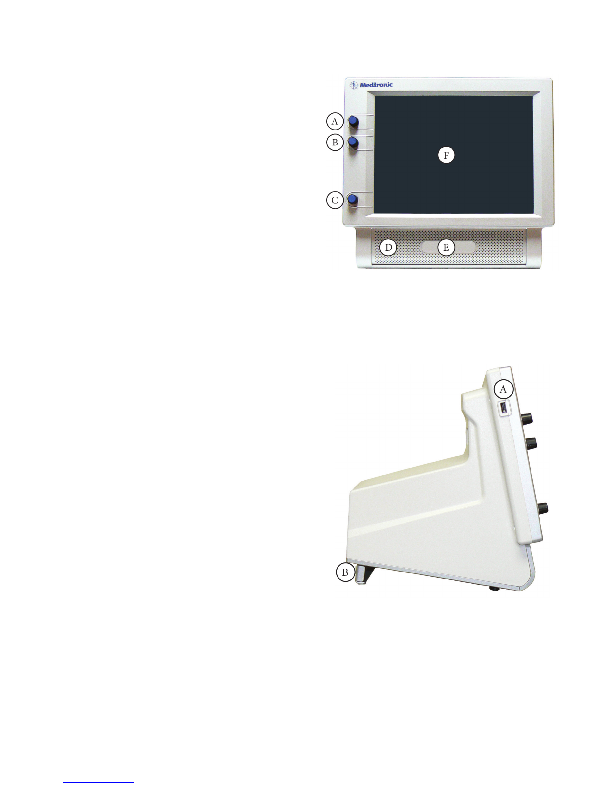
Console Front
A. STIM1 stimulus adjustment.
B. STIM2 stimulus adjustment.
C. Volume adjustment.
D. e Speaker provides audio alarms, acoustic EMG monitoring, and
voice prompts.
E. Product name.
F. Touchscreen – e Touch Screen displays EMG waveforms and
controls many of the functions of the NIM® 3.0.
Console Left Side
Contraindications
e NIM® 3.0 is contraindicated for use with paralyzing anesthetic
agents that will signicantly reduce, if not completely eliminate, EMG
responses to direct or passive nerve stimulation.
Customer Care
Medtronic Xomed, Inc.
6743 Southpoint Drive North
Jacksonville, FL 32216 USA
manuals.medtronic.com
Help Line
(800)‑874‑5797
International Service
International customers should contact their local Medtronic Xomed
oce.
Nerve Integrity Monitor
A. USB Out: e USB Out is an industry standard USB type connector
that can be used with mass storage devices.
B. Anti‑Glare Stand: is device is used to change the viewing angle of
the NIM® 3.0 screen. It is shown in the tilted (up) position.
7
Page 8
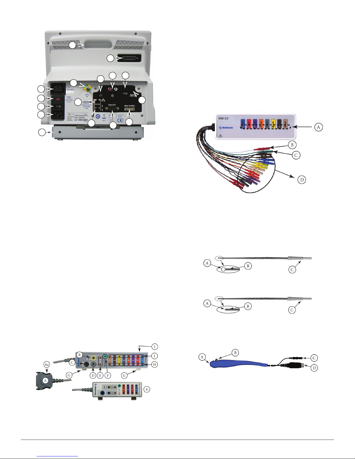
Console Rear
O
K
M
E
A
B
C
D
P
A.
Accessory Power Outlet: e Accessory Power Outlet used with
F
N
G
L
J
I
H
the approved NIM® 3.0 Accessories (i.e. the approved printer power
supply only).
B. Fuse Access: e AC power fuses are located on the back of the
units.
C. Power Switch: e power switch turns the power ON or OFF.
D. Power Connector: e power cord plugs into the back of the NIM®
3.0 System console. e input fuses and accessory output is in the
power entry module. Plug the power cord into the A/C power outlet.
E. Equipotential: Uniform potential.
F. For future use.
G. USB Out: e USB Out is an industry standard USB type connector
(two port) that can be used with mass storage devices/printer/
keyboard.
H. VGA Output: Used only to connect NIM‑Neuro® 3.0 System to
microscope. Not active on NIM‑Response® 3.0 System.
I. Surgeon Mini Screen Port: Output connection to Surgeon Mini
Screen or video recorder.
J. Muting Detector Input: Near‑eld radio frequency detector.
K. Patient Interface Connector: e patient interface connector is a
25‑pin D‑sub.
L. Handswitch APS™only.
M. RCA Audio Jack: An RCA audio jack is provided to output an audio
signal that can be overlaid onto a video signal when using industry
standard recording devices. e output will be audio line level (1 Vp‑
p).
N. Mini Jack: Standard conguration is for private listening through
Stereo Headphones.
O. Carry Handle for transporting unit.
P. Anti‑Glare Stand: is device is used to change the viewing angle of
the NIM® 3.0 screen, it is shown in the tilted up position.
Important:
Intraoperative use of the VGA Out, and RCA Phone Jack requires
special considerations to remain compliant with IEC/EN60601‑1.
Contact Medtronic Xomed for recommendations if intraoperative use of
the VGA Out, RCA Phone Jack.
Patient Interface
D. Stimulus (out) Jack
E. Stimulus Return
F. Electrode ground: signal return for patient electrodes.
G. Patient Interface Clips.
H. Negative Electrode Jacks: Negative electrodes have black wires and
color‑coded plugs.
I. Positive Electrode Jacks ‑ Positive electrodes have matching color‑
coded wires and plugs.
J. e Patient Interface fuses are for Stimulator Output and are
specically tested for ECU protection.
Use Xomed 11270048 Fuse, 5 x20mm, 32mA, 250 V. Order 8253075
Fuse Kit for replacements.
K. NIM‑Response® 3.0 Patient Interface shown for reference only.
Patient Simulator
e Patient Simulator is used for troubleshooting and demonstrating the
system without the need for patient interaction.
A. Stimulator pads (Simulated Events).
B. Stimulator return (anode) plug.
C. Electrode ground plug
D. Simulated subdermal electrode plugs.
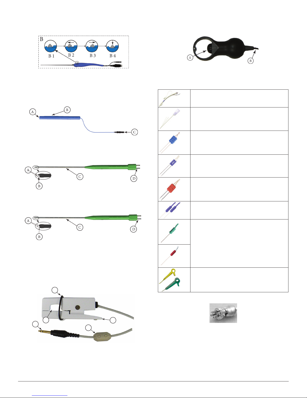
Stimulator Probes/Handles
e Stimulator Probes and Handles carry stimulus current from the
console, via the Patient Interface, to the patient.
Monopolar
Ball Tip Probe
A. Stimulus to Patient Contact Area
B. Insulated Sleeve
C. Probe Base
Standard Prass Flush Tip Probe
A. Stimulus to Patient Contact Area
B. Insulated Sleeve
C. Probe Base
Incrementing Monopolar Probe Handle
e Incrementing Probe provides the ability to adjust the stimulus, and
to print or save events from within the surgical site.
A. Patient Interface to console connector
Aa. Connector release.
B. Stimulating Instrument Jack or Stimulator Probes (Monopolar or
Bipolar).
C. Incrementing Probe Control Jack: Connects Incrementing Probe
controls to the NIM® 3.0.
8
A. Probe Jack
B. Toggle Button
C. Stimulus Plug
D. Toggle Button Control Plug
Incrementing Probe Stimulus Adjustment
e (single use) Incrementing Probe provides the surgeon with the
means to adjust the stimulation current at the surgical site.
Nerve Integrity Monitor
Page 9
Note: If the incrementing probe handle malfunctions, immediately
disconnect the Toggle Button Control Plug from the Incrementing
Probe Control jack from the Patient Inter face and use console
touch screen buttons to adjust stimulus cur rent.
B1 Toggle button normal or at rest.
B2 Increase current.
B3 Decrease current.
B4 Press and hold saves current screen to memory (for Reports)
and to selected peripheral device (Printer and/or USB ash
drive).
Universal Monopolar Probe Handle
APS™ Electrode Handswitch
APS™ Electrode Handswitch – e handswitch cycles through the APS™
functions (O, On, Slow, Fast).
A. umb Switch
B. Cable
Electrodes
Electrode types recommended for use with the NIM® 3.0 System
EMG Endotracheal Tube: Contact electrodes
designed to monitor both vocal cords.
Hookwire Electrode: Two small wires attached to the
end of a hypodermic needle. Injected intramuscularly
(then the hypodermic needle is removed) e wires
are insulated to within 3 mm of the end and are
designed to obtain a more specic response.
A. Probe Jack.
B. Handle.
C. Stimulus Plug.
Bipolar
Side-by-Side Stimulating Probe
A. Stimulus to Patient Contact Area.
B. Insulating Sleeve.
C. Stainless Steel Tubing.
D. Cable Connection.
Prass Flush Tip Stimulating Probe
A. Stimulus to Patient Contact Area.
B. Insulating Sleeve.
C. Stainless Steel Tubing.
D. Cable Connection.
Muting Detector
See Precaution P8.
e Muting Detector Probe is designed to detect the presence of
electronic noise from external devices (such as electrocautery/
electrosurgical unit) that may cause interference on the EMG monitor.
A
Paired Subdermal Electrodes: Non‑insulated high
performance electrodes with 2.5mm spacing.
Prass Paired Electrodes: e electrodes are insulated
to within 5mm of the end with 5mm spacing.
Muscle‑specic single use.
Prass Paired Electrodes Small Hub: e electrodes
are insulated to within 5mm of the end with 2.5mm
spacing. Muscle‑specic single use.
Subdermal Needle Electrodes: Non‑insulated high
performance electrodes 12mm long with a 0.4mm
diameter.
Electrode Ground (Green with Green Wire) and
Electrode Stimulus Return (Red with White Wire):
Always locate these electrodes in a non‑innervated,
electrically neutral area (electrically neutral areas are
where the bone is close to the skin and the electrode
will not contact muscle tissue). Ground should also
be located between the stimulator and monitoring
electrodes.
Stimulating Electrodes 2 mm and 3 mm.
E
D
A.
Anti‑slide Ring.
B. Insulating Sleeve.
C. Ferrite.
D. Cable Connector.
E. Electronic Noise Detection Area.
Nerve Integrity Monitor
C
Power Cords
B
1897821 Power Cord, 6 Meter, 115V
1895820 Power Cord Standard
1895822 Power Cord, Europe
1895823 Power Cord, Japan, 100V
9
Page 10
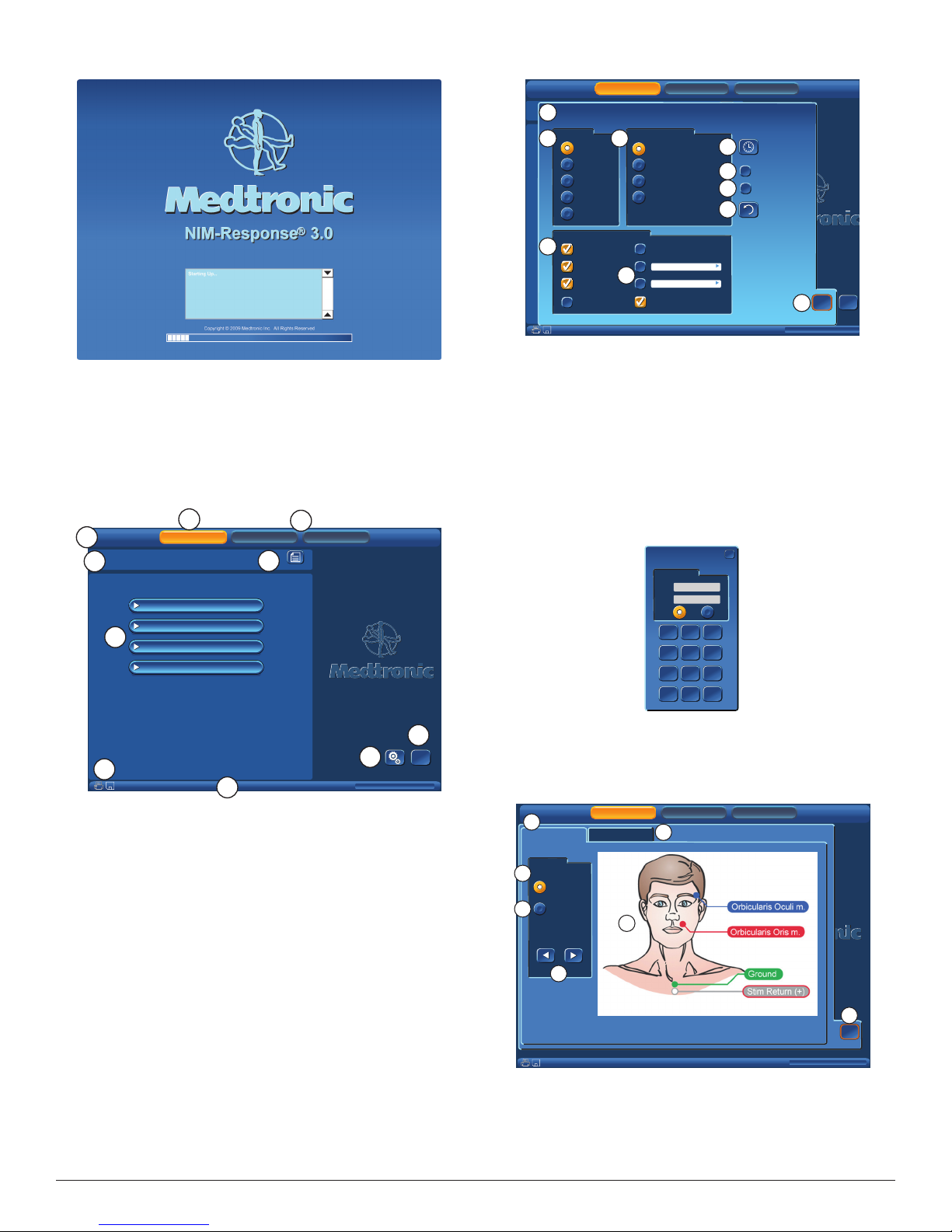
The Splash Screen
B
0
0
0
Self Test
An internal integrity check is automatically performed each time the
system is turned ON. (See Warning W8)
On Power‑up a series of messages are briey displayed. en the console
does a series of self‑tests on the hardware.
Set-Up Mode
Select Procedure Step 1 of 2
C
Information
Information
Reports
Reports
NIM- Respon se® 3. 0
NIM- Respon se® 3. 0
NIM- Respon se® 3. 0
A
1. Select Procedure
1. Select Procedure
I
H
Setup
Setup
Step 1 of 2
Step 1 of 2
Neuro/Otology
Neuro/Otology
Head/Neck
Head/Neck
Peripheral
Peripheral
Custom Procedures
Custom Procedures
Monitoring
Monitoring
J
Global Settings
Information
Information
I
H
G
F
PM
321
654
987
Reports
Reports
S et D a t e
S et D a t e
a nd T i m e
a nd T i m e
D ia g n o s t i c M o d e
D ia g n o s t i c M o d e
E na b l e D B S a v i n g
E na b l e D B S a v i n g
R es t o r e
R es t o r e
D ef a u l t s
D ef a u l t s
NIM -Resp onse® 3.
NIM -Resp onse® 3.
NIM -Resp onse® 3.
X
X
OK
OK
E
Global
Global
Global
Help
Global
Help
Settings
Settings
Settings
Settings
GUI vxxxx.x.xxxxx DSP vxxx.x.xx.xxxx
?
?
Monitoring
Monitoring
G lo ba l Se tt i ng s
G lo ba l Se tt i ng s
1 /2 7 / 2 0 0 7 1 1 : 3 4 : 06 P M
1 /2 7 / 2 0 0 7 1 1 : 3 4 : 06 P M
1 /2 7 / 2 0 0 7 2 3 : 3 4 : 0 6
1 /2 7 / 2 0 0 7 2 3 : 3 4 : 0 6
2 7/ 1 / 2 0 0 7 2 3 : 3 4 : 0 6
2 7/ 1 / 2 0 0 7 2 3 : 3 4 : 0 6
2 00 7 / 1 / 2 7 2 3 : 3 4 : 0 6
2 00 7 / 1 / 2 7 2 3 : 3 4 : 0 6
Mo n i t or i n g P r of e s s io n a l
Mo n i t or i n g P r of e s s io n a l
<title>
<title>
N ot e s
N ot e s
5/1/2009 9:00 AM
5/1/2009 9:00 AM
1. Select Procedure
1. Select Procedure
A
L an gu a ge
L an gu a ge
B
E ng l i s h
E ng l i s h
Neuro/Otology
Neuro/Otology
F re n c h
F re n c h
I ta l i a n
I ta l i a n
G er m a n
G er m a n
S pa n i s h
S pa n i s h
Custom Procedures
Custom Procedures
D at a F ie l ds fo r C a se No t es
D at a F ie l ds fo r C a se No t es
C
S ur g e o n
S ur g e o n
P at i e n t N am e
P at i e n t N am e
P at i e n t I D
P at i e n t I D
P at i e n t D OB
P at i e n t D OB
* indicates default settings have been changed
* indicates default settings have been changed
Setup
Setup
Step 1 of 2
Step 1 of 2
D at e/ T im e F o rm a t
D at e/ T im e F o rm a t
J
Head/Neck
Head/Neck
Peripheral
Peripheral
D
is panel is accessed by pressing the Global Settings button in any of
the Set‑Up Mode Screens.
A. Global Settings Panel.
B. Language panel: Select language.
C. Data Fields: Select the elds to be populated in the Case Information
Screen.
D. Blank data elds: Allows the operator to name two elds that will
appear in the Case Information Screen.
E. OK button will close Global Settings.
F. See Buttons and Indicators.
G. Enable DB Saving check box (o by default), this will turn on the .db
option in Reports Mode.
H. Diagnostics Mode: Not for end users. Should be used only under the
direct supervision of Medtronic Xomed personnel.
I. Opens a data entry key pad for setting the date and time.
Date Format: 03/18/2008
Date Format: 03/18/2008
Time Format: 09:24:34 AM
Time Format: 09:24:34 AM
Set Date/Time
Set Date/Time
03/18/2008
Date:
03/18/2008
Date:
09:24:34 AM
Time:
09:24:34 AM
Time:
AMAMPM
Clear
Clear
Ok
0
Ok
D
?
Global
Global
Settings
Settings
?
Help
Help
* indicates default settings have been changed
* indicates default settings have been changed
G
F
5/1/2009 9:00 AM
5/1/2009 9:00 AM
E
GUI vxxxx.x.xxxxx DSP vxxx.x.xx.xxxx
is is the default screen, requiring the operator to select an existing
procedure or begin a new (custom) procedure.
Optional: Operator may enter/change Date, Time, Language, or Data
Fields via Global Setting button.
A. Tool Bar: Used to select any of the major (3) functional Modes.
B. Set‑Up Button: Selected by default.
C. Monitoring and Report Button‑ not selectable at this operation.
D. Help Button: See Help screen.
E. Global Settings Button: See Global Settings screen.
F. Time and Date Bar: is bar shows the time and date as set in the
Global Settings panel. In addition it displays the GUI and DSP
version.
G. Print and Save Icon: ese icons are displayed automatically (in
all screens with a time and date bars) only if a USB drive and/or a
Printer are connected.
H. Select Procedure: Drop down menus.
I. Set‑Up Wizard Navigation Bar.
J. Information Button: See Case Information.
• Date entry elds for date and time.
• AM and PM radio buttons.
J. Date/Time Format: Used to select how date / time is displayed. e
default format is sensitive to language.
Help
A
Electrode Placement
Electrode Placement
Diagram
Diagram
C
Nerve
Nerve
Procedure
Procedure
D
VII (2ch)
VII (2ch)
Setup
Audio Samples
Audio Samples
F
Monitoring
Monitoring
B
Setup
E
5/1/2009 9:00 AM
5/1/2009 9:00 AM
is screen will display help graphics for locating electrodes or sample
audio sounds.
A. Electrode Placement: is tab selects help graphics for locating
electrodes.
B. Audio Sample: is tab enables sample three sound buttons:
• Pulse
• Train
Reports
Reports
MIN-Response® 3.0
MIN-Response® 3.0
MIN-Response® 3.0
Global
Global
Settings
Settings
GUI vxxxx.x.xxxxx DSP vxxx.x.xx.xxxx
Help
Help
G
OK
OK
?
?
Help
Help
10
Nerve Integrity Monitor
Page 11
• Burst
C. Diagram/Nerve: Radio button selects help graphics by nerve
number/name.
D. Diagram/Procedure: Radio button selects help graphics by
Procedure. See Place Electrodes Step 2 for example.
E. Previous Next Buttons: For changing graphics.
F. Graphics display area.
G. OK button will close Help screen.
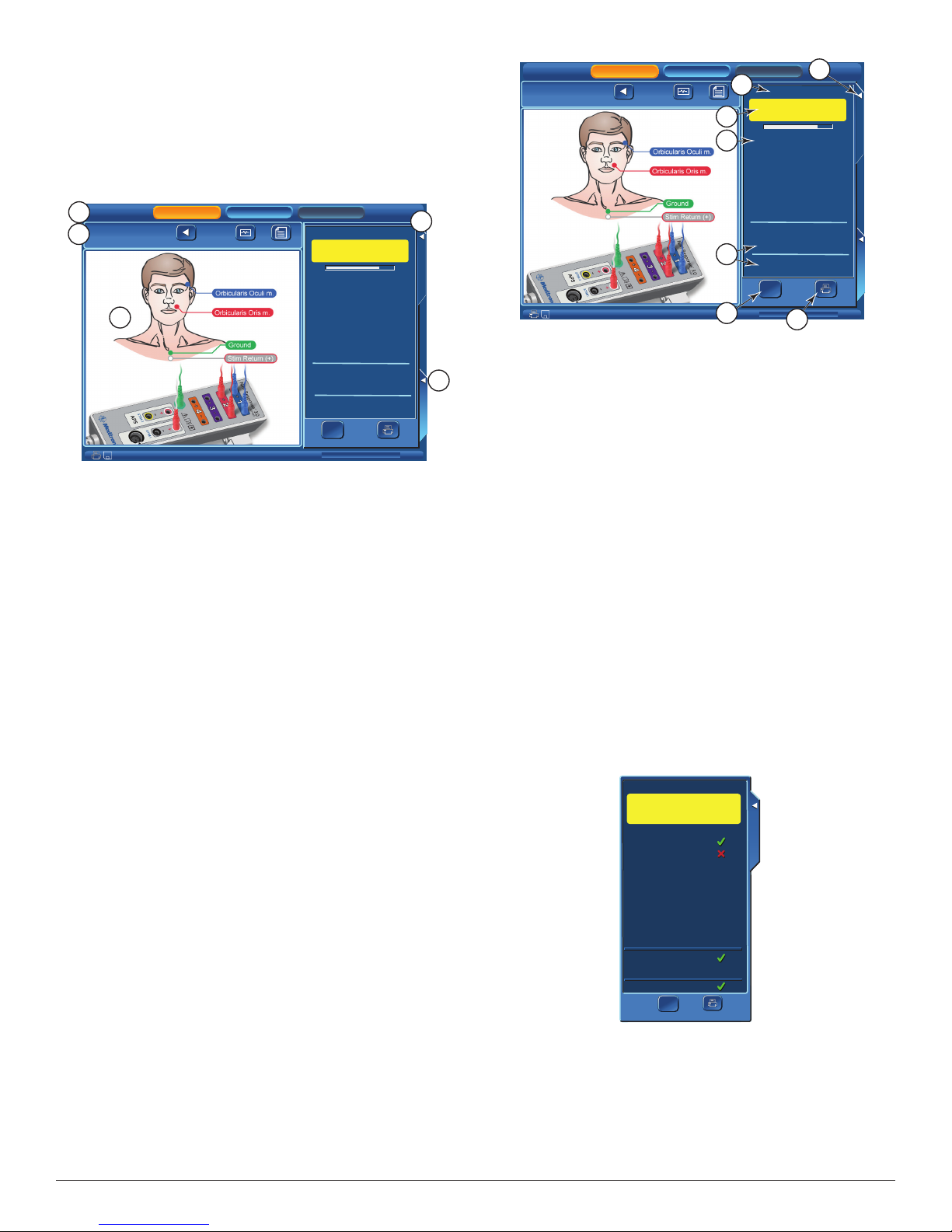
Place Electrodes Step 2 of 2
Opens automatically aer selecting a factory installed procedure.
A
Mastoid
Mastoid
B
2. Place Electrodes
2. Place Electrodes
Setup
Setup
Previous
Previous
Step 2 of 2
Step 2 of 2
Monitoring
Monitoring
Monitor
Monitor
Information
Information
E
11/4/2008 10:00AM
11/4/2008 10:00AM
Reports
Reports
Electrode Check
Warning: EMG Monitoring
Is Disabled
Please Wait
Please Wait
1 - Orbicularis Oculi
1 - Orbicularis Oculi
2 - Orbicularis Oris
2 - Orbicularis Oris
Stim 1 Return
Ground
Ω
Ω
Show Details
GUI vxxxx.x.xxxxx DSP vxxx.x.xx.xxxx
C
Electrode Check
Electrode Check
?
?
?
?
?
?
?
?
Print
D
Procedure Settings
Procedure Settings
is screen will assist the operator with electrode location. It also runs
an electrode check, this screen shows that electrodes are being tested.
Note: If changes to the procedure are to be made and saved,
then those changes must be made before selecting the Monitor or
Monitoring button.
Note:
• is screen can be bypassed by selecting the Monitor or Monitoring
button.
• If bypassed there will be no pre-surgery impedance values of the
electrodes, ground, or STIM1/2 available to printed/saved reports.
• If the patient interface, electrodes, ground, STIM1/2 were
disconnected when this screen was opened, any printed report will
show a failure of the impedance values of the disconnected item(s).
A. Tool Bar: Used to select any of the major (3) functional Modes.
B. Set‑Up Wizard Navigation Bar.
• Previous: Returns to the Select Procedure screen.
• Monitor: Opens the Monitoring screen. See Monitoring Mode
for details.
Note: If changes were made in the Electrode Check panel , the
Procedure S ettings panel,or one of the Procedure Settings/
Advanced Settings Tabs a dialog box will open asking if the
operator wishes to save said changes.
• Information: Opens the Case Information screen. See Case
Information for details.
C. Electrode Check Tab: Closes/Opens Electrode Check panel. See
Electrode Check Panels for details.
D. Procedure Settings Tab: Opens/Closes Procedure Settings Panel. See
Procedure Settings Panel for details.
E. Electrode Placement Graphic: Shows electrode placement for both
the patient and patient interface.
Mastoid
Mastoid
2. Place Electrodes
2. Place Electrodes
Setup
Setup
Previous
Previous
Step 2 of 2
Step 2 of 2
Monitoring
Monitoring
Monitor
Information
Monitor
Information
11/4/2008 10:00AM
11/4/2008 10:00AM
A
C
D
E
F
Reports
Reports
Electrode Check
Warning: EMG Monitoring
Is Disabled
Please Wait
Please Wait
1 - Orbicularis Oculi
1 - Orbicularis Oculi
2 - Orbicularis Oris
2 - Orbicularis Oris
Stim 1 Return
Ground
Ω
Ω
Show Details
GUI vxxxx.x.xxxxx DSP vxxx.x.xx.xxxx
G
B
Electrode Check
Electrode Check
?
?
?
?
?
?
Procedure Settings
Procedure Settings
?
?
Print
is screen shows that a two (2) channel surgery (Mastoid) was selected.
Channel 1 will be used to monitor Orbicularis Oculi and channel 2
Orbicularis Oris.
B. Closes Electrode Check panel.
C. Monitoring is disabled when the Electrode Check panel is open
D. Electrode status eld:
• Progress bar: Displayed while electrodes are being tested.
• Question Marks: Question marks are visible while the electrode
test is running and will be replaced with pass (green check mark)
or fail (red x) mark.
E. STIM1, STIM2, and Ground status elds.
Note:
• ere is no STIM status (blank) if Bipolar is selected in the Type
Panel (located in the Advanced Settings/Stimulation Panel).
• ere is no STIM2 status (blank) if a single stimulator is
connected.
• STIM2 will be displayed aer it is turned on using the Activate
button located on the main screen or selecting the STIM2 or APS™
check box on the Procedure Settings/Stimulation Panel.
• STIM 1, STIM 2, Ground - A question mark aer the test has
completed means that no channel electrode or ground was
connected therefore no value (impedance) was read. At least one
channel electrode and ground must be connected for the system to
read STIM 1, STIM 2, and Ground impedance.
F. Show Details button: See Electrode Check/Show Details.
G. Print Button: Sends the electrode, ground, and STIM1 & 2
impedance values to the Printer.
Note: Print button is displayed only if a printer is connected.
Electrode Check Panel Pass/Fail
e impedance values of the electrodes to the patient are measured to
conrm the integrity of the connection.
Electrode Check
Electrode Check
Warning: EMG Monitoring
is Disabled
1 - Orbicularis Oculi
1 - Orbicularis Oculi
2 - Orbicularis Oris
2 - Orbicularis Oris
Electrode Check
Electrode Check
Electrode Check
Electrode Check, checks the integrity of the patient to Patient Interface
connections. It is also the only location where electrode type in use can
be changed.
Electrode Check Panel
is panel can be accessed from two (2) locations:
A. Electrode Check Panel is typically displayed in the Set‑Up Mode
with Place Electrodes Screen. It may be opened or closed at this
screen using the Electrode Check Tab.
Note: Changes made in the Set-Up Mode can be saved. The only
saveable change (saveable to a new or existing procedure) that can
be made at this panel is the electrode type being u sed. If printing a
report it will include electrode values, it will not include electrode
type .
Nerve Integrity Monitor
Stim 1 Return
Stim 1 Return
Ground
Ground
Ω
Ω
Print
Show Details
Show Details
Print
is screen shows that channel 1, stimulus return, and ground electrodes
have passed where channel 2 has failed.
11
Page 12
Electrode Check Show Details Panel
Press the Show Details Button to see the actual impedance values. See
the Electrode Troubleshooting Guide in this section.
Electrode Check
Electrode Check
Warning: EMG Monitoring
is Disabled
Subdermal
Subdermal
(+) 5.9kΩ
(-) 5.9kΩ
(+) 6.0kΩ
(-) 55.8kΩ
1 - Orbicularis Oculi
1 - Orbicularis Oculi
A
2 - Orbicularis Oris
2 - Orbicularis Oris
∆ 0.0kΩ
∆ 48.2kΩ
Electrode Check
Electrode Check
Case Information
Opens aer pressing Information Button.
A
Mastoid
Mastoid
B
Enter Case Information
Enter Case Information
Surgeon
Surgeon
Patient ID
Patient ID
Patient Name
Patient Name
Setup
Setup
Previous
Previous
Monitoring
Monitoring
Monitor
Monitor
Reports
Reports
Print
Print
8.1kΩ
6.6kΩ
A.
Electrode Type Button.
Stim 1 Return
Stim 1 Return
Ground
Ground
Hide Details
Hide Details
Electrode Type Panel
Electrode Check
Electrode Check
Warning: EMG Monitoring
is Disabled
Subdermal
Subdermal
1.5kΩ
1.5kΩ
0.7kΩ
0.7kΩ
Hide Details
Hide Details
(+) 5.9kΩ
(-) 5.9kΩ
(+) 6.0kΩ
(-) 55.8kΩ
Sub derm al
Sub derm al
End otra che al Tu be
End otra che al Tu be
Hoo kwir e
Hoo kwir e
Pra ss P air ed
Pra ss P air ed
Sur face
Sur face
Print
Print
1 - Orbicularis Oculi
1 - Orbicularis Oculi
2 - Orbicularis Oris
2 - Orbicularis Oris
2 - Orbicularis Oris Electrode Type
2 - Orbicularis Oris Electrode Type
Stim 1 Return
Stim 1 Return
Ground
Ground
∆ 0.0kΩ
∆ 48.2kΩ
8.1kΩ
6.6kΩ
Electrode Check
Electrode Check
At this screen Radio Buttons are used to select the type of electrode
being used (Subdermal by default).
Electrode Troubleshooting Guide
Symptom Cause Solution
Electrode
impedance is too
high.
> 10KΩ for
subdermal
electrodes
> 10KΩ for EMG
tube
Electrode
impedance
≤0.1KΩ
Electrode reading
is (+ or ‑) O
or
Δ = = = =
Question mark
at STIM 1/2,
and Ground in
Electrode Check
Panel
• Electrode dislodged
from patient, but not
completely out.
• High resistance in
electrode.
• Electrode pin not rmly
inserted into patient
interface.
• Positive and negative
electrodes touching
below surface of skin.
• Extremely low
impedance, particularly
in EMG tubes.
• Electrode laying on skin
surface.
• Electrode placement
insecure.
• Dirty electrode tip.
• Electrode cable is
broken.
• Electrode pin
disconnected from
patient interface.
• No channel electrode
connected.
• Ground not connected.
• Insert dislodged
electrode; tape down
in place.
• Remove and replace
with new electrode.
• Check connection
at Patient Interface
box.
• Remove and relocate
electrodes.
• Re‑insert electrode
in question.
• Remove and
replace electrode in
question.
• Check connection
to Patient Interface
box.
• Connect at least one
channel electrode.
• Connect ground.
C
MIN-Response® 3.0
MIN-Response® 3.0
Notes
Notes
MIN-Response® 3.0
D
Procedure Settings
Procedure Settings
E
?
?
Global
Help
Global
Help
Settings
Settings
7/1/2008 9:00 AM
7/1/2008 9:00 AM
GUI vxxxx.x.xxxxx DSP vxxx.x.xx.xxxx
is screen is for data entry into preselected data elds. See Global
Settings for data eld selection.
A. Tool Bar: Used to select any of the major (3) functional Modes.
B. Set‑Up Wizard Navigation Bar: Previous, Monitor see Buttons and
Indicators.
C. Case Information: By pressing any of the information elds a
keyboard for data entry will open.
D. Procedure Settings Tab: Opens Procedure Settings panel.
E. Global Settings, and Help Buttons: See Global Settings.
Procedure Settings Panel
is panel can only be accessed in the Set‑Up Mode Place Electrodes
screen.
Note: Changes made in this panel can be saved (saveable to a
new or existing procedure). If printing a snapshot it w ill include
changes to:
• Channels
• STIM1
• Event reshold
• Procedure name (if changed)
If printing a report it will also include changes to STIM2:
Stimulation
Stimulation
B
Event Thershold
Event Thershold
D
Save
Save
Channels
1: Orbicularis Oculi
1: Orbicularis Oculi
2: Orbicularis Oris
2: Orbicularis Oris
3: Inactive
3: Inactive
4: Inactive
4: Inactive
5: Inactive
5: Inactive
6: Inactive
6: Inactive
7: Inactive
7: Inactive
8: Inactive
8: Inactive
Stim1
Stim1
30.0
2
mA
Stim2
Stim2
100
2
µV
E
+
+
APS
APS
+
+
Advanced
Advanced
Settings
Settings
F
Procedure Settings
Procedure Settings
A
C
e user can review and/or change the monitoring settings for the
procedure.
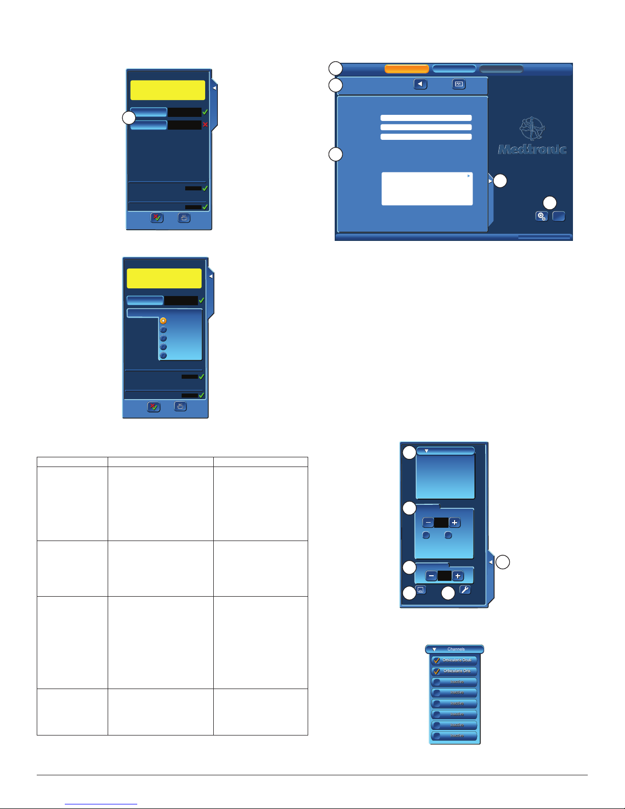
A. Channels: used to add, remove, or change the names of the channels
1. Press the Channel button, drop down list of channels will open.
12
2. Press an active channel to inactivate that channel. Press an inactive
channel to open the Muscle Name keyboard.
Nerve Integrity Monitor
Page 13
3. Muscle Name:
a. Use the Scroll buttons to locate an existing muscle group.
b. Highlight (touch the screen) the muscle name.
c. Press OK to enter name and exit.
Or
a. Key in (type) new muscle name.
b. Press OK to enter name and exit.
B. Stimulation Panel: Used to adjust STIM1 stimulus and STIM2 or
APS™stimulus (if selected).
Example shows panel with STIM2 selected.
C. Event reshold Panel: Adjust the event threshold, the range is from
20μV to 2500μV in increments of 5μV.
D. Save Button:
a. Opens save option panel.
b. Save option panel gives the operator the option to overwrite the
existing procedure, create a new procedure or cancel.
E. Advanced Settings Button: See “Advanced Settings” for details.
F. Closes the panel.
Advanced Settings
Advanced Settings function:
• Advanced Settings adjustments made in the Set‑Up Mode
(Procedure Settings Panel), can be used for the current session
OR saved.
• Advanced Settings adjustments made in the Monitoring Mode
(Control Panel) are eective only for the current session and
CANNOT be saved.
When the Advanced Settings button is pressed, a screen is opened with
tabs that allow access to the functions described.
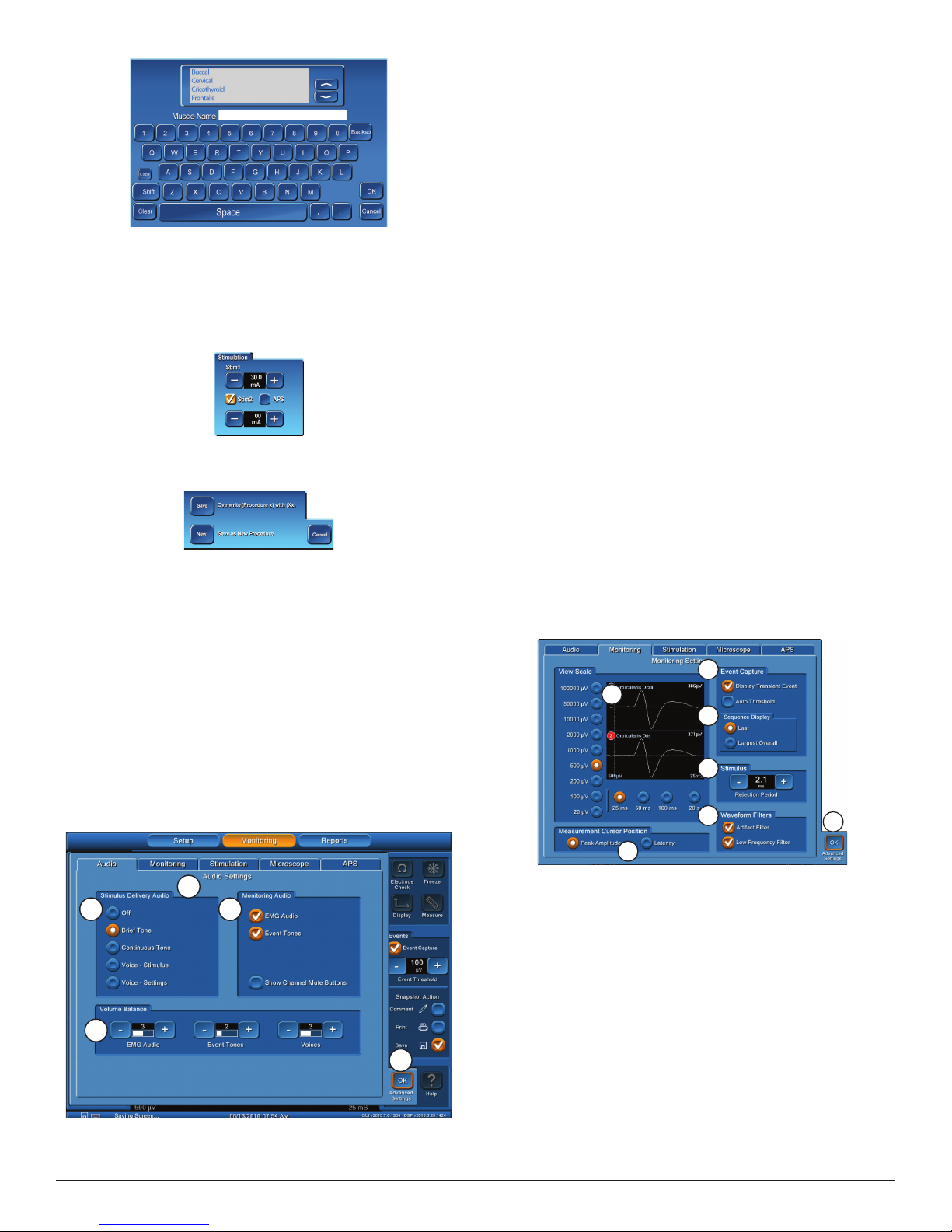
Audio Tab
Please review “Audio – Understanding What You Hear” with this
section.
A
B
D
A.
Audio Settings: congures system to determine what sounds will be
heard during monitoring and balance between various sounds.
Note: If APS™ is active, the Event Tones volume balance will
control the APS™ volume balance.
Nerve Integrity Monitor
C
E
B. Stimulus Delivery Audio: e default setting is Brief Tone.
Additional options:
• Brief Tone (default): Delivery of stimulus current is accompanied
by a brief warbled tone.
• Continuous Tone: Delivery of stimulus current is accompanied
by a continuous, warbled, high‑low tone (referred to as “Stimulus
Warble Tone”).
• Voice ‑ Stimulus: Delivery of current to the surgical eld is
announced by the word, “STIMULUS”.
• Voice ‑ Setting: Delivery of current to the surgical eld is
announced by the value of the stimulus setting.
Note: Stimulus Delive ry Audio is not heard when an event has
occurred.
C. Monitoring Audio: ere are two options, EMG Audio and Event
Tones. At least one selection must always be active however, both
options may be selected.
• EMG audio: is the amplied sound of muscle activity that is
heard instantaneously as the nerve is stimulated. All EMG
activity, regardless of amplitude, is audible when the EMG
audio is ON. e EMG activity may sound like a low‑pitched
“drumbeat”, a high‑pitched “crackle,” or a “growl”. When multiple
channels are monitored, it is unlikely that you will be able to
dierentiate the EMG signals as to their channel of origin strictly
by the sounds they produce.
• Event Tones: are heard when the EMG amplitude is larger than
the Event reshold setting. e Event Tones are easily heard
over O. R. noise and are heard at the same time with the EMG
audio, previously mentioned.
User can dierentiate channels by tones pitch. e tone for channel 1
activity is lower in pitch than the channel 2 and so on for channels 3
through 8. When EMG activity exceeding the event threshold occurs
at the same time on multiple channels, only two of the tones sound
at once.
User may allow individual EMG channels to be muted by selecting
Show Channel Mute Buttons.
D. Volume Balance: Sound levels can be adjusted using the + and –
buttons for EMG Audio, Event Tones and Voices. A numeric value
and white bar graph will indicate the setting relative to full scale
(scale is 1 to 5).
E. OK button will close Advance Settings panel.
Monitoring Tab
C
A
D
E
F
B
A. View Scale, see Control Panel Display Button.
B. Measurement Cursor Position, selects the measurement start
position:
• Peak Amplitude ‑ selects the largest peak to peak value
• Latency ‑ will place the cursor where the response to a
“Stimulation” begins.
See also Control Panel Measurement Button.
C. Event Capture/Auto reshold Check Box:
If Event Tones are continuous for 10 seconds:
• Auto reshold will automatically calculate a new Event
reshold (to a maximum of 400μV).
• All activity less than the new Event reshold will be heard as
raw EMG.
• EMG activity greater than the new Event reshold or greater
than 400μV will generate Event Tones.
• Additionally, if the Voice setting is selected, it will announce the
amount of threshold increase.
• e Event reshold will return to the original value aer 10 –
20 seconds of no, or decreased, event activity.
D. Event Capture/Sequence Display/Last (default setting)
G
13
Page 14
• If Last and Event Capture (see Control Panel) are selected, the
most recent event will be displayed until replaced with a new or
more recent event.
• If Largest Overall and Event Capture (see Control Panel) are
selected, and multiple events occur over a period of 4 seconds
then the largest event from the series of events will be displayed
as Largest x of x (example 3 of 5).
• is will remain displayed until replaced with the next event or
next largest event from a 4 second series of events.
Note: that neither Event Capture nor Largest are available when
the x-axis time s cale is set to 1 0 seconds (it is only available in the
50ms time scale).
E. Stimulus/Rejection Period, is an adjustable delay allowing the small
amount of electronic noise caused by stimulation (Stimulus Artifact)
to stabilize before reading EMG data.
Stimulus Artifact Example
a. Original Rejection Period setting.
b. Stimulus Artifact.
c. Move Rejection Period line to here to avoid artifact.
d. EMG Response.
Note: In previous versions of the N IM, Stimulus Rejection Period
was referred to as Stimulus Artifac t or Artifact Delay.
Special Note on Recognizing Artifact
e NIM® 3.0 System features sophisticated artifact rejection technology
designed to provide highly sensitive and accurate monitoring. However,
there may be electrically generated signals in the range of true response
that the NIM® 3.0 System cannot dierentiate.
Examples:
• A transcutaneous stimulator used by the anesthesiologist might
generate an audible signal.
• Any external nerve locator/stimulator not synchronized (Muting
Detector) with the NIM® 3.0 System.
• Electrical leakage from faulty thermal cautery units. You can
identify the spurious signals by their lack of surgical context
(there was nothing the surgeon was doing at that moment that
could have caused a true EMG response).
• If the recording electrodes and the stimulator (+) or (‑) cables
become tangled the resulting stimulus artifact might be
spuriously detected as an EMG event. Be careful to route the
recording electrodes away from stimulator cables.
• e pace pulse generated by pacemakers may be detected and
displayed by the NIM® 3.0 System as a rhythmic artifact signal.
is is caused by the electrode ground or stimulus return
electrodes being in close proximity to the pacemaker or its lead
wire(s). e artifact caused by the pacemaker may be reduced
by repositioning the Electrode Ground and Stimulus Return
electrodes to the top of the patient’s shoulder (the Acromion)
(use shoulder opposite operated side). e Electrode Ground
(green plug green wire) and Stimulus Return (red plug white
wire) electrodes should be positioned about 5 cm apart, green
Proximal, red Distal. Once the electrodes are repositioned, verify
that the Stimulus Return and Impedances Ground are within
tolerance (review Panels / Electrode Check ).
• ere may also be interference‑generated signals in the range
of true response that the NIM® 3.0 System cannot dierentiate.
An example of this type of artifact signal could occur when
the surgeon strikes two metal instruments together within the
surgical eld, such as a metal suction tube with a dissecting
tool. Such signals are typically monophasic with fast onset and
oset. at is, the signals appear on the screen as sharply peaked
responses in one direction only.
• While these artifacts are signicantly dierent in waveform
appearance from true EMG events (which have a biphasic
waveform), the magnitudes of these signals can reach several
hundred microvolts causing the event tone to sound. However,
the surgeon is usually aware when two instruments have been
struck together and can, therefore, relate such “false positive”
responses to the surgical context.
F. Waveform Filters
• Artifact Filter: Selecting this Check Box enables the detection of
artifact as “Spiked Waveforms” (see Mechanical Stimulation in
Appendix C)
• Low Frequency Filter: Low Frequency Response is generally
caused by the movement of the electrodes, electrode wires, tissue
etc. is can result in a response that is not a true EMG response.
Selecting this Check Box enables a lter that reduces Peak to
Peak amplitude (about 20%) in a frequency range below 70Hz
reducing unwanted response. e lter is on by default for all
procedures.
G. OK button will close Advanced Settings panel.
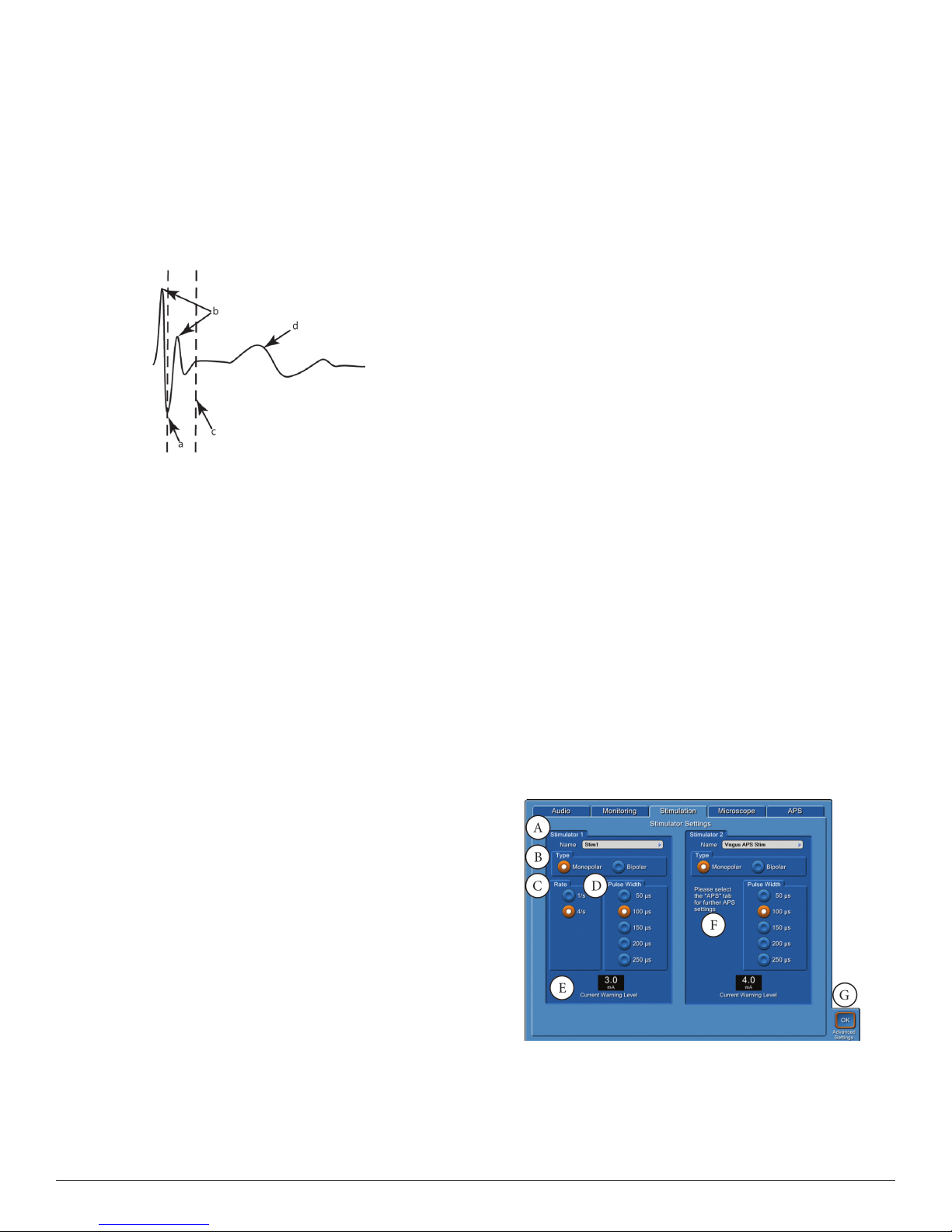
Stimulation Tab
Important Note on Stimulator Adjustments
e absolute stimulus intensity required to adequately stimulate any
motor nerve is determined by a complex combination of several factors
including (but not limited to) the following:
• e functional health of the nerve itself.
• e type of stimulation probe used (monopolar or bipolar).
• Proximity to the nerve.
• e pulse width of the stimulus.
You should use the smallest amount of stimulus necessary to elicit a
detectable EMG event. Stimulus current levels of 0.3mA may be high
enough for adequate direct monopolar stimulation of the facial nerves,
but may elicit little or no response when monitoring motor evoked
potentials. e best guideline for setting the stimulus intensity level is to
use the lowest amount that produces an EMG event.
The surgeon should be aware:
• at STIMULUS is continuously being applied to the
STIMULATOR probe and/or the APS™).
• STIMULATING the patient is the result of physical contact
between the patient and the STIMULATOR probe.
• e STIMULATOR probe should be kept ISOLATED when
NOT STIMULATING the patient (except APS™).
Note: Stimulator adjustment involves the adjustment of the
Cur rent, Rate , Pulse Width, and the Stimulus/Rejection Period.
Note: To prevent inadvertent high stimulus levels, the rst time the
stimulus level exceeds the Current Warning Level , a dialog box will
open:
Stimulus in excess of 3 mA
Press OK to allow stimulus
If using the procedures Lower Extremity, Knee, or Ankle the stimulus
level warning is set at 12.0 milliamperes.
A. Name/text eld, pressing the text eld will open the Stimulator 1 or 2
Name keyboard.
14
Nerve Integrity Monitor
Page 15

a. Use the Scroll buttons to locate an existing probe.
b. Highlight (touch the screen) the probe name.
c. Press OK to enter name and exit.
Or
a. Touch screen at Stimulator (1 or 2) Name.
b. Key in new name.
c. Press OK to enter name and exit.
B. Type Panel is used in the selection of monopolar or bipolar probes.
By default monopolar is selected. If bipolar probes are being used the
operator must change probe type at this location.
C. is panel is used for making adjustments to the stimulus Rate .
D. is panel is used for making adjustments to the stimulus Pulse
Width.
A Pulse Width (duration time of each pulse)
B Rate (number of pulses per second)
E. Maximum Current Setting used to adjust stimulator current if being
accessed from Set‑Up/Procedure Settings/Advanced Settings. No
adjustment is available if accessed from Monitoring/Control Panel/
Advanced Settings.
F. If using an APS procedure all adjustments to STIM 2 should be done
using the APS Tab except for the Name/text eld (A) of this section.
If using a monopolor or bipolor probe adjustments are the same as
STIM 1.
G. OK button will close advance settings panel.
Repeat for Stimulator 2 panel.
NOT E: If an APS™ procedure has been selected, then the
Stimulator 2 Panel/Rate adjustment will be found on the APS™
Tab.
Microscope Tab (available on the NIM-Neuro® 3.0 only)
Note: When the “Display Overlay” check box is NOT checked all other
parts of the panel are not displayed.
e following graphic shows all default settings.
Note: Not all video input microscopes are compatible with the
NIM® 3.0 System. Contact Customer Care at 1(800)874-5797 for
specifics.
• Operator can select between displaying any event or events
Example
resulting from stimulation.
B. Operator can select where the overlay is displayed.
• Location is ne tunable at plus or minus 60 pixels using the
horizontal or vertical oset adjustment.
C. Resolution should be set to the value specied by the microscope
manufacturer.
D. Select to display an event until replaced with a new event, or have the
display turn o aer a selected period of time.
E. Select to have display show data only or data and waveform. Example
shows data with waveform.
F. Select OK button will close advance settings panel.
APS™ Tab (Automatic Periodic Stimulation)
A
B
A.
APS™Channels: Channel 1 and 2 checked by default.
D
C
E
B. Alarm Limits:
• Amplitude sets the alarm to sound if the EMG response
tolerance limit is reached (default is 50% less than baseline and
lower than 2000µV).
• Latency sets the alarm to sound if the latency tolerance limit is
reached (default is latency value plus(+) 10%).
C. Stimulation: “Slow Rate” and “Fast Rate” are selected at this panel.
e operator may switch between these rates when in monitoring
stimulation. Default setting is:
• Slow Rate 10/min (10 per minute)
• Fast Rate 1/S (1 per second).
NOT E: The Pulse Width adju stment for APS™ is found on the
Stimulation Tab Stimulator 2 panel.
D. APS™ EMG:
• Show APS™ Waveforms selected by default, the waveforms from
APS™ stimulation is shown on the “Monitoring Screen” in blue
with EMG response in white.
• Mute APS™ EMG Audio: Mutes the APS™ EMG Audio (pop, pop,
pop sound).
E. OK button: will close advance settings panel.
A. Display Overlay is used to activate the microscope overlay video
output.
Nerve Integrity Monitor
15
Page 16

Monitoring Mode
C DB
A
E
F
G
H
I
J
M
N
P
N
O
K
is screen is displayed by selecting the Monitor or Monitoring button.
It is the screen displayed during surgery and shows all EMG activity.
APS™ is not shown.
A. Tool Bar: Used to select any of the major functional Modes.
B. Set‑Up Button: opens the Set‑Up Screen.
C. Monitoring Button: Opens the Monitoring Screen.
D. Report Button: Opens the Reports Screen.
E. STIM1 Panel: Displays the stimulation setting (large numbers), the
measured value (in the small window), and adjustment buttons for
the STIM1 current settings.
F. STIM2 Panel: If inactive it will display the “Activate” button. If active
as a second stimulator it’s display is the same as STIM1.
If an APS™ procedure has been selected then the Vagus APS™STIM
Panel will be displayed:
Vagus APS Stim
Vagus APS Stim
Vagus APS Stim
1.00
1.00
0.00 mA
Vagus APS Stim
1.00
1.00
1.00 mA
270 µV
Q
Q
O
5 µV
L
J. Print and Save Icon: ese icons are displayed automatically (in
all screens with a time and date bars) only if a USB drive and/or a
Printer are connected.
K. Date, Time, GUI, and DSP version.
L. Control Panel Tab: Opens Control Panel.
M. Channel Label: Displays the channel number and nerve being
monitored.
N. Trace: Displays stimulus nerve activity/inactivity.
O. Scale: Displays screen scale settings.
P. Artifact Delay: Shows where artifact ends and EMG begins.
Q. Amplitude: Displays in microvolts activity level on each channel:
• A box will enclose the activity level of any channel showing an
event.
• If there are multiple channel events, the box will enclose the
largest.
• If the system detects a signal (response) that is outside the range
of the systems ability to measure (80 ‑ 100,000μV or higher)
“Out of Range” will be displayed.
Control Panel
347 µV
B
A
75 µV
G
H
e Control Panel, is used for additional settings and monitoring
features.
A. Display Button, opens the Scale Panel.
C
D
E
F
APS On
APS On
Pulse Rate
Pulse Rate
Baseline
Baseline
APS On
APS On
Pulse Rate
Pulse Rate
Baseline
Baseline
• e APS™ On, check box, Slow Rate, and Fast Rate buttons
will be inactive (grey) until aer the APS™Baseline has been
established.
• See System Set‑Up/ APS™Settings for how to establish a baseline.
G. Events Panel: is panel displays the Event reshold settings and
allows the operator to adjust the setting level (in 5μV increments).
• EVENT THRESHOLD is a highly sensitive lter used to dene
where EMG activity becomes signicant.
• EMG activity exceeding this “THRESHOLD” is dened as an
“EVENT” and results in Event Tones (alarms) sounding.
• Set “Event reshold” by pressing plus/minus buttons to
increase or decrease the value as desired. Setting is displayed in
micro‑Volts.
a. If the Event Capture is turned on (default) the Snapshot Button
will be visible.
Note: Event Threshold adjust buttons are unavailable for APS™
monitoring. See Control Panel to adjust Event Threshold.
H. Snapshot Button: Saves current screen to memory (for reports) or to
selected peripheral device:
• Comments Icon Snapshot Option ‑ See Control Panel.
• Print and Save Icon Snapshot Option ese icons are displayed
automatically if a USB drive and/or a Printer are connected ‑ See
Control Panel.
Note: Snapshots (print or save) show event information only and
will not include the impedance values of the electrode, ground, or
STIM1/2 .
I. Volume Panel: Displays adjustable volume setting.
Sound levels can be adjusted using the volume knob (see Console
Front, Item C). A numeric value and white bar graph will indicate
the setting relative to full scale. e default setting is 50.
347 µV
c
a
b
a.
e vertical portion of the EMG display represents Amplitude
and the scale is adjustable (500μV by default). e vertical
screen is divided into equal sections per channel with 1/2 of each
channel positive and 1/2 negative. Each channel is separated by a
solid blue line.
b. Time scale is represented by the horizontal portion of the EMG
display and is adjustable (25mS by default) (see Advanced
Settings / Monitoring Tab). e screen is divided into equal
sections. is diers from the “Amplitude scale” in that the
“Time scale” selection is the entire horizontal portion of the
screen.
c. OK Button, closes Scales panel.
Note: Chang ing either scale only affects how the data appears on
the screen. It does not modif y the s ensitivity of the unit.
B. Electrode Check: See Electrode Check Panel.
16
Nerve Integrity Monitor
Page 17

C. Freeze: Pressing the “Freeze” button causes the screen contents to
be displayed, unchanged, until the next press of the Freeze button
“unfreezes” the display. is is useful to view an event over an
extended period.
Note: Any events that take place when Freeze is on are not
displayed.
D. Measure Button: for viewing details of an event waveform.
227 µV, 5.25 mS
a
a
27 µV, 5.25 mS
a.
e on screen display (green) will show the amplitude (μV) and
347 µV
55 µV
5.25
b
c
d
time (mS) at the cursor location.
• Time is measured from zero (0) not from Stimulus/Rejection
Period.
• Amplitude is measured from the channels zero (0) with a
minus (‑) sign for negative numbers and no minus sign for
positive numbers.
b. e time will also be shown in the display.
c. Cursor Position buttons will move the vertical (green line) cursor
le or right in increments of 0.25mS.
d. e cursors and displayed value will turn o when the measure
OK button is pressed.
E. Events/Event Capture: Captures and holds EMG activity that exceeds
the EVENT THRESHOLD.
F. Events/Snapshot Action:
• Comments: Opens comments panel allowing comments and
Event Titles (titles may be entered via keyboard or selected
from a pre‑dened list) to be added to the captured event when
the Snapshot button is pressed. ese comments/title will be
displayed on the printed and/or saved event.
• Comments and Event Titles can be modied in Reports Mode.
• Print: Sends captured event to the printer with comments if
selected when the Snapshot button is pressed.
• Save: Sends captured event to the USB mass storage device with
comments if selected when the Snapshot button is pressed.
G. Advanced Settings button: Opens Advanced Settings. See Set‑Up
Mode/Advanced Settings for information. Adjustments made to
the Advanced Settings in the Monitoring Mode (Control Panel) are
eective only for the current session and CANNOT be saved.
H. Help: Is available as abbreviated assistance on the Monitor Display.
B
C
D
H
E
A
D
F
G
I
A.
APS™ STIM Panel: Shows default settings aer running APS™
Baseline.
B. APS™ Waveform: Appears as a Blue Trace (on all channels if “Show
APS Waveforms” is on(default) in Advanced Settings APS tab).
C. EMG Waveform: Appears as a White Trace (on all channels).
D. Limit Lines: e upper limit for Latency and lower limit for
Amplitude are displayed as red dotted lines.
E. Baselines: For Latency and Amplitude are displayed as white dotted
lines.
Waveforms: For Latency are a series of turquoise dots and a series of
blue dots represents Amplitude.
F. Latency and Amplitude are separated by a scaled line. is line is the
time base as shown at top le of screen (L). e scale marks are one
minute apart.
G. Values: For the alarm (if sounded) are shown at the Limit Lines and
the measured value of the last pulse is shown at the Baselines.
H. Alarm Indicator: is indicator shows that a alarm was selected
(default) on the Audio Setting Panel. Also serves as a Mute button.
I. Values: EMG measured values are displayed in white with the largest
value boxed in yellow, APS™ measured values are displayed in blue.
K
L
M
The APS™ Monitoring Screen
APS™ is a process wherein a nerve at risk is continuously being
stimulated. is stimulation is monitored and charted continuously in
real time. Trends can be plotted and observed.
e plotted characteristics are:
• EMG (response to stimulation)
• Latency (time from stimulation to the “Onset” of the EMG
response)
e plotted chart displays peak‑to‑peak values for EMG amplitude
and latency responses for each stimulation pulse delivered. Every
turquoise dot represents a single EMG amplitude response. Each blue
dot represents a latency response. A red dot is an out of limit condition
resulting in an alarm sounding.
Nerve Integrity Monitor
J
J. APS™ ON/Advanced Settings: When the APS™ ON check box is
checked (orange with white check mark) the Advanced Settings
button is NOT selectable.
If the APS™ button is turned OFF:
• e advanced settings button will be selectable.
• e APS™ portion of the screen (right side) will close and there
will be an APS™ tab added next to the control panel tab. e
operator can open and close the inactive APS™ screen using this
tab.
• APS™ monitoring will resume when the APS™ check box is
turned ON.
K. Latency marker: A small purple X showing where the latency value
was located on the trace.
L. Time Base: see F.
M. Case duration.
17
Page 18

The Reports Mode
A
Note: All stored data (Snapshots) are lost when unit is powered
off.
e Report Mode allows the user to quickly compose and print/save
three general types of reports; Event Records, Log Files and APS™
Records. Report templates are provided to simplify creating reports.
e Reports Mode can be active while audio monitoring continues in
the background. All work that is performed in Reports will be saved
by the system, if Reports is exited and the user returns to Monitoring.
In this way, a report could be started midway through a monitoring
session. When the user returns to Monitoring to complete the session,
all previous work will be available when the user returns to the Reports
Mode. When the system is intentionally turned o, all monitoring
session data are lost.
ere are three steps in the process:
• Select Report Format
• Specify Report Content
• Create Report
Reports Step 1 of 3 (Select Report Format)
is screen is used by Snapshots, Log Files, and APS™ Records.
A
1. Select Report Format
1. Select Report Format
B
Select Case
Select Case
Case 1 - Procedure: Mastoid
C
Surgeon Name:
Patient Name:
Notes:
Select Report Type
Select Report Type
D
A. Tool Bar: Used to select any of the major (3) functional Modes.
B. Active Screen Bar. Next button will be displayed aer a report type
has been selected.
C. Select Case: Select a case from multiple cases. Next and/or Previous
button will be displayed if more than one case is in memory.
D. Report Type: Select from available report types.
E. Sample display area of selected report type.
Snapshots/Event Reports
1. Select Report Format
1. Select Report Format
Snapshots
Snapshots
Log Files
Log Files
APS Records
APS Records
Setup
Setup
Setup
Setup
Setup
Setup
Setup
Setup
Monitoring
Monitoring
Step 1 of 3
Step 1 of 3
5/1/2009 9:00AM
5/1/2009 9:00AM
Monitoring
Monitoring
Step 1 of 3
Step 1 of 3
Reports
Reports
Information
E
Reports
Reports
Information
GUI vxxxx.x.xxxxx DSP vxxx.x.xx.xxxx
Setup
Setup
Setup
Setup
2. Choose Report Content
2. Choose Report Content
B
Choose Events
Choose Events
Event Title
C
1
Orbicular is Oculi
Orbicular is Oculi
Orbicular is Oris
2
Orbicular is Oris
500µV
Event Comments
Event Comments
Unselect All
Start: 4:30AM
4:30AM
D
A.
Tool Bar: Used to select any of the major (Set‑Up not available in
471µV
50µV
25 mS500µV
E
Step 2 of 3
Step 2 of 3
Event
1 of 4
11/4/2008 6:50AM
Include In
Report
11/4/2008 10:00AM
11/4/2008 10:00AM
Monitoring
Monitoring
Select Events
Select Events
5:30AM 6:30AM
Reports
Reports
Information
1
Orbicularis Oculi
Orbicularis Oculi
Orbicularis Oris
2
Orbicularis Oris
500µV
1
Orbicularis Oculi
Orbicularis Oculi
Orbicularis Oris
2
Orbicularis Oris
500µV
5:15AM
6:08AM
1
471µV
2
50µV
500µV
25 mS500µV
478µV
20µV
25 mS500µV
Orbicularis Oculi
676µV
Orbicularis Oculi
Orbicularis Oris
50µV
Orbicularis Oris
25 mS500µV
F
1 to 4 of 4
GUI vxxxx.x.xxxxx DSP vxxx.x.xx.xxxx
1
Orbicularis Oculi
Orbicularis Oculi
Orbicularis Oris
2
Orbicularis Oris
500µV
5:55AM5:40AM
End: 6:30AM
31µV
450µV
25 mS500µV
Reports) functional Modes.
B. Active Screen Bar.
C. Choose Events (In APS™ reports Choose Events panel is Choose
Sessions panel):
• Scroll through each captured event (captured event: whenever
Snapshot Button was/is pressed) with the Previous and Next
buttons.
• When an event is displayed the operator may enter or modify an
Event Title or Comment.
• Selecting the check box will move the displayed event to the
Selected Events panel. Events are displayed in the report in the
order they are selected.
D. Select All button: Used to move all events to the Selected Events
panel (In APS™ reports there is no Select All button).
E. Time‑Line panel (In APS™ reports there is no time line panel):
• Graphically shows all the captured events and time.
• Events selected to appear in a report will be orange in color not‑
selected events will be white.
F. Selected Events: Shows the collection of events to be included in the
Report.
Snapshots/Events Reports Step 3 of 3
e third step allows the user to choose a report format and generate
(print or save) the report. Depending on the report type, this step takes
on dierent looks.
A
3. Create Report
3. Creats Report
B
Report Format
Report Format
C
Setup
Setup
Setup
Setup
1 Record
Per Page
Monitoring
Monitoring
Step 3 of 3
Step 3 of 3
Reports
Reports
Information
Sample Preview
Sample Preview
Select Case
Select Case
Case 1 - Procedure: Mastoid
Surgeon Name:
Patient Name:
Notes:
Select Report Type
Select Report Type
Snapshots
Snapshots
Log Files
Log Files
APS Records
APS Records
5/1/2009 9:00AM
5/1/2009 9:00AM
Aer the Report Type has been selected (Snapshots) the operator will
press the next button in the Active Screen Bar to open Step 2 of 3 screen.
Choose Report Content Step 2 of 3
APS™ reports and Snapshot reports are very similar. e dierences are
noted in the following.
18
GUI vxxxx.x.xxxxx DSP vxxx.x.xx.xxxx
4 Records
Per Page
Case Notes
F
D
E
A.
Tool Bar: Used to select any of the major (Set‑Up not available in
Reports) functional Modes.
B. Active Screen Bar.
C. Report Format: Select 1 record per page or 4 records per page.
D. Case Notes: Add any notes to the Report Summary page.
E. Report Options:
• Print button will send the report to the attached printer.
• Save button will send the report to the attached USB mass
storage device.
Save the formatted report, as a .pdf on the USB drive. e
lenames will be formatted with the report type, year, month,
day and time, for example, EventReport_20090528112530.pdf.
• Reports are located in a Case Folder titled:
• date and patient ID or
Print
Save
5/1/2009 9:00AM
5/1/2009 9:00AM
GUI vxxxx.x.xxxxx DSP vxxx.x.xx.xxxx
Nerve Integrity Monitor
Page 19

• date and patient name or
• with no patient ID or name, date and sequential case number
will be used.
F. Sample Preview: Displays an example of the type of report selected.
Snapshots/Events Reports .pdf Image Example
Log Files
Log Files Step 1 of 3 See Reports Step 1
of 3
Log Files Step 2 of 3
A log le that contains data for all events (not only Snapshot Events) is
maintained by the system throughout the case. An event in the Log File
is created when the EMG value exceeds the Event reshold value. e
data in this le can be used to either construct Log File Reports or to be
exported in comma‑delimited format for o‑line analysis. For a Log File
Report, this wizard step allows the user to select event data using ‘data
lters’.
A
B
2. Choose Report Content
2. Choose Report Content
Setup
Setup
Setup
Setup
Monitoring
Monitoring
Step 2 of 3
Step 2 of 3
Reports
Reports
Note: Record 1 and 2 are “Stimulated” events with STIM1
showing 0.80/0.80mA that is the set value / by the read value.
Record 3 and 4 are Non-Stimulated events with STIM1 reading
0.80/0.00mA that again is the set value / by the read value of zero.
Event Filter
Event Filter
Snapshot Events
All Events
C
Snapshot Events: 4
Stimulated Events: 0
F
Non-Stimulated Events: 8
No. of Sequences 4
A.
Tool Bar: used to select any of the major (Set‑Up not available in
All Events
All Events
Selected Events: 8Total Events: 8
Stimulated Events
Non-Stimulated Events
D
5/1/2009 9:00AM
5/1/2009 9:00AM
Event Sequences
Event Sequences
Suquenecs Filter
E
GUI vxxxx.x.xxxxx DSP vxxx.x.xx.xxxx
Reports) functional Modes.
B. Active Screen Bar.
C. Event Filter: choose Events captured using Snapshot or All Events.
D. All Events: additional lter criteria allowing the user to select
Stimulated Events, Non‑Stimulated Events, or both. Note All Events
Panel is visible only if the All Events button is pressed.
E. Event Sequence: A sequence is a series of events separated from each
other by less than one second.
When the Sequence Filter is selected the user can sort event
sequences by Last or Largest:
• Last: When selected, only the last event in a sequence will be
included in the report. is is the default when Sequence is
selected.
• Largest: When selected, only the event that contains the greatest
value within a sequence will be included in the report.
F. Status box: shows statistics about the logged events, including the
number of events that will be included in the Report (Selected
Events).
Note: Case Notes are entered using any of the Case Notes text
boxes.
Comments were entered when the Snapshot button was pressed or
when creating the report.
Nerve Integrity Monitor
Log Files Step 3 of 3
A
B
3. Create Report
3. Creats Report
Case Notes
Setup
Setup
Monitoring
Monitoring
Step 3 of 3
Step 3 of 3
Setup
Setup
C
D
A.
Tool Bar: used to select any of the major (Set‑Up not available in
Print
Reports) functional Modes.
B. Active Screen Bar.
C. Case Notes: Add any notes to the Report Summary page.
Save
5/1/2009 9:00AM
5/1/2009 9:00AM
Reports
Reports
Sample Preview
Sample Preview
E
Information
Information
GUI vxxxx.x.xxxxx DSP vxxx.x.xx.xxxx
19
Page 20

D. Report Options:
• Print button will send the report to the attached printer as a pdf
image.
• Save button: will open a dialog box allowing the operator to send
the report to the attached USB mass storage device.
Save Report Data to USB Drive
Save Report Data to USB Drive
Log Reports .csv (in Excel) Example
.PDF
.PDF
.CSV
.CSV
.DB
.DB
Cancel
Cancel
•
Save the formatted report, either to a .pdf image le, .csv
Save Image of Report (.pdf file)
Save Image of Report (.pdf file)
Save a Data File (.csv file)
Save a Data File (.csv file)
Save Database (.db file)
Save Database (.db file)
Don’t Save
Don’t Save
data le or a .db database le on the inserted USB drive.
e lenames will be formatted with the date and time,
report type and appropriate extension. For example,
LogReport_20090618081932.pdf would be a Log Report Image
created 2009 June 18 at 08:19:32.
• Reports are located in a Case Folder titled:
• date and patient ID or
• date and patient name or
• with no patient ID or name, date and sequential case number
will be used.
E. Sample Preview panel will show an example of the report type prior
to saving or printing.
Log Reports pdf Image Example
APS™ Reports
1. See Reports Step 1 of 3 and select/press APS™ Reports.
• Note: Functionally APS™ Reports and Snapshot Reports use
all the same screens/Panels with the same function. Please see
Snapshot Reports for instructions.
APS™ Reports .pdf Image Example
20
Creating a Report
Snapshots Report
1. See Reports Step 1 of 3 and select/press Snapshots.
2. Choose Report Content (Snapshots) Step 2 of 3 Screen opens.
3. In the Choose Events panel:
• Using the Next and Previous buttons, select an event you wish to
copy into the report.
• Press the blue arrow in the white Event Title box if you wish to
title the event or modify an existing title.
• Press the blue arrow in the white Event Comments box if you
wish to enter comments about the event or modify an existing
comment.
Nerve Integrity Monitor
Page 21

• Press the Include in Report Check Box.
e selected event will appear in the Selected Events panel.
or
Pressing the Select All Button will move all events to the Selected
Events panel. You may still use the Next and Previous buttons to
move through the selected events and enter/modify event titles
and comments as needed.
4. Press the Next button on the Active Screen Bar.
5. Create Report (Event Records) Step3 of 3 Screen opens.
6. Select form the Report Format panel weather you wish to view
one(1) or four(4) records per page using the radio buttons.
7. Press the blue arrow in the white Case Notes box to enter any
comments you have on the case.
Note: Event Title and Event Comments appear at the top and
bottom of the event where the y were entered and in the Summary
section of the report. Case Notes are in the Summary section only.
8. Print and Save button will open a dialog box allowing the operator to
send the report to the attached USB mass storage device.
Save Report Data to USB Drive
Save Report Data to USB Drive
Special Functions and Features
Visual Alarms and Warnings
e operator may encounter the following warnings and should respond
appropriately.
.PDF
.PDF
.CSV
.CSV
Cancel
Cancel
•
Save the formatted report, either to a .pdf image le, .or csv data
Save Image of Report (.pdf file)
Save Image of Report (.pdf file)
Save a Data File (.csv file)
Save a Data File (.csv file)
Don’t Save
Don’t Save
le.
Log les
1. See Reports Step 1 of 3 and select/press Log Files.
2. Choose Report Content (Log Files) Step 2 of 3 Screen opens.
3. In the Event Filter panel:
• Select the Snapshot Events Radio button and only events that
were saved by pressing the Snapshot button on the Main Screen
will be available to Step 3 of 3 in the Log File Report.
or
• Select the All Events Radio button:
If All Events Radio button was selected:
• All Events, and Event Sequences panels will open.
• All Events: Stimulated and Non‑Stimulated Events are
selected by default. is can be adjusted to any combination
of the two if desired.
• Event Sequences: O (default) if selected operator will need
4. Press the Next button on the Active Screen Bar.
5. Create Report (Log Files) Step3 of 3 Screen opens.
6. Press the blue arrow in the white Case Notes box to enter any
7. Print and/or Save the report using the Print and/or Save buttons.
to select between Last (default) and Largest.
comments you have on the case. Case Notes are located between the
End of Report and Electrode Check sections of the Log File.
Nerve Integrity Monitor
21
Page 22

Audio – Understanding What You Hear
e NIM® 3.0 System Nerve Monitor produces many dierent sounds
throughout surgical procedure that require understanding by the person
performing monitoring. In addition to EMG sounds, various beeps and
voices provide useful information.
Alarms
e alarms draw attention to any condition, which prevents proper
monitoring. None of the audible alarms should be ignored. One must
assume that valid monitoring has stopped and determine immediately
why the alarm sounded.
ere are three distinct alarms:
• BEEP Alarm: e high‑pitched, repetitive beep is used to register
failure of internal microprocessor hardware. If you hear it at any
time other than at power up, stop using the NIM® 3.0 System and
contact Medtronic. See Customer Care section.
• Bleedle Alarm: is is a three‑note alarm (Blee‑Dle Deet) that
cannot be disabled. It repeats until the responsible condition
is remedied. e alarm is heard once under the following
conditions:
• Check Electrode
• Muting
• and Power Up
• APS™ alarm: e high‑pitched three‑note alarm is used to notify
the user when changes in the amplitude or latency exceed the
user dened limits. ere is a delay of at least 6 seconds before
this alarm will repeat.
For more information on these two conditions please see Special
Functions and Features / Muting conditions.
• Voice Alarms: ere are two voice alarms that are selectable
and work in unison with the bleedle alarm. ey can be turned
on or o and have volume controls. ese alarms are “check
electrodes” and “muting,” and are described in System Set‑Up.
Voice Annunciation
ere are several voice annunciation types, stimulation delivery
conrmation, numeric stimulator current values, and activation of auto
threshold.
NIM® 3.0 System Voices
Point Five reshold increased
Zero Six Check electrodes
One Seven Electrodes
Two Eight Stimulus
ree Nine
Four reshold decreased
Threshold / Voice
ese voices are used as part of the Auto reshold feature when
automatic adjustments are made. Please see the Auto reshold section
of the manual.
e NIM® 3.0 System has two (2) reshold voices: “reshold
increased” ‑ “reshold decreased”.
Help / Voices
“Check electrodes” is announced when contact with an electrode is lost.
Stimulus Delivery Audio
Tone
e stimulus tone announces the delivery of current to the patient.
• If Continuous Tone is used, then delivery of stimulus current is
accompanied by a continuous, warbled, high‑low tone (referred
to as “Stimulus Warble Tone”).
• If Brief Tone is used, then delivery of stimulus current is
accompanied by a brief warbled tone.
Note: Stimulus tones will not sound for stimulus current levels
below 0.05mA.
Voice
e stimulus voice announces the delivery of current to the surgical eld
by voice.
• Voice ‑ Stimulus: With “Stimulus”, delivery of current to the
surgical eld is announced by the word, “STIMULUS”. It may be
turned on or o and has volume control.
• Voice ‑ Setting e “Setting” voice announces the value of the
STIMULUS setting. It also announces any new stimulus setting
when adjustments are made.
Example: 0.50mA would be announced as “Point Five”. It may
be turned on or o and has volume control.
Note: Voice - Setting or Voice - Stimulus will not sound for
stimulus current levels below 0.05mA.
Other EMG Responses (Samples are available in the Help Screen).
• Burst ‑ Brief tone: Caused by electrical stimulation, direct nerve
contact, irrigation, or thermal changes.
• Train Tones lasting seconds to minutes: Caused by nerve excited/
irritated, irrigation, drying, bumping, or anesthesia.
• Pulse ‑ Repeated tones: Caused by electrical stimulation, tumor
mapping, verifying nerve integrity.
Muting
e Muting Detector is normally clamped around the active cable of
an electrosurgical instrument that would otherwise be interfering with
monitoring. Do not include the grounding pad cable in the jaws of the
Muting Detector. It may also be connected to other equipment cables,
such as electrocautery, ultrasonic debulking devices (e.g. CUSA), or
other external devices, which generate interfering signals. Always attach
the Muting Detector close to the output jacks of the electrosurgical or
other unit rather than near the hand piece the surgeon uses. More than
one output cable may be clamped within the Muting Detector jaws at
one time.
Monopolar Electrosurgical Instrument Clamping
e following table shows the power level for satisfactory muting
performance of electrosurgical unit.
Monopolar Electrosurgical Unit
5‑100W
Muting Conditions
Check Electrode:
• As soon as contact with an electrode is lost aer removal.
• e channel shows a background noise waveform.
• Aer approximately 30 seconds, “Electrode O” is displayed
in Yellow Text on a zero (0) amplitude waveform line.
• e channel will be muted until connection is restored.
Muting from External Source:
As soon as the Muting Detector senses current ow, the dialog box “
Monitoring/WARNING EMG MONITORING IS DISABLED/Muting
from external source” and the system will be in mute. Aer 20 to 30
seconds, the bleedle alarm will sound followed by the “Muting” voice.
e bleedle alarm will repeat every 20 to 30 Seconds until the condition
is remedied.
22
Nerve Integrity Monitor
Page 23

STIM Bur Guard
e STIM Bur Guard provides stimulating current to standard
Medtronic burs in both static and dynamic modes. e STIM Bur Guard
locks onto any Visao® handpiece, while the cable connects to a port on
the IPC® System or XPS® 3000 (REF 1897102BF). A separate cable then
connects to the NIM® Patient Interface Box. Wires within the STIM Bur
Guard make contact with the uncoated bur and carry the stimulating
current to the bur tip.
Prior to using this device, the user must be familiar with the NIM®
Systems User’s Guide, the Bur manual, the STIM Bur Guard User’s
Guide, and the IPC® System or XPS® 3000 (REF 1897102BF) User’s
Guide.
Compatible equipment:
• XPS® Console (1897102BF)
• IPC® Console
For more information related to the STIM Bur Guard system contact
your local Medtronic representative
Note the following Contraindications for Use:
e use of paralyzing anesthetic agents will signicantly reduce, if
not completely eliminate, EMG responses to direct or passive nerve
stimulation. Whenever nerve paralysis is suspected, consult an
anesthesiologist.
Muting Detector Set-Up
See Precaution P8.
1. Open the Muting Detector jaws and insert the cable from the
electrosurgical instruments, ensuring that the wire is free to move
and the jaws are completely closed.
2. Route the wire straight through the clamp.
Standard clamping
System Set-Up
Operating Room Set-Up
e NIM®3.0 System Nerve Monitor has a few characteristics that need
to be taken into consideration when setting up the OR. Some of these
characteristics include, but are not limited to, external devices, trac
patterns, sterile areas, color‑coding, grounding, and muting detection.
Set the NIM®3.0 System on a table or cart located about 3 meters from
the surgical eld but as far as possible from the electrosurgical unit.
Also, consider trac patterns and sterile areas. e surgeon may have
further preferences as to location and visibility.
Typical Set-Up (shown with IPC®)
A. Anesthesia Equipment
B. IPC® System or XPS® 3000 (REF 1897102BF only) if used
C. Nursing Supplies / Surgical Instruments
D. Scrub Nurse
E. NIM® Monitor
F. Microscope
G. Surgeon
H. Electro Surgical Unit
I. Anesthesiologist
Anesthesia Requirements
All decisions regarding anesthesia are the responsibility of the attending
licensed medical practitioner administering the anesthesia. Because all
intraoperative monitoring discussed in this User’s Guide requires that
EMG activity be recorded from a muscle or muscles, it is important
that the muscle(s) not be paralyzed during the surgery or at least
during those parts of the surgery when the nerve(s) being monitored
is (are) deemed at risk by the surgeon. It is important that the surgeon
discuss these issues pre operatively with the attending licensed medical
practitioner administering the anesthesia.
Nerve Integrity Monitor
Note: Bipolar clamping is normally not needed but if power level is
Monopolar and Bipolar (if needed) Clamping
very low it may be necessary to loop the single conductor around
and through the clamp see instruction 7 for clamping instructions.
3. Slide the cable so the probe is near the main unit of the
electrosurgical instruments, not near the hand piece(s).
4. Slip the upper side of the anti‑slide ring around the end of the
Muting Detector to form a “U” around the cable. Pull it snugly
against the probe’s lower jaws (see Steps 1 & 2).
Step 1 Step 2
5. Do not clip the Muting Detector to the grounding pad cable.
6. e Muting Detector and Patient Interface cables should be secured
to the oor with tape or other non‑slip/trip device.
23
Page 24

e auxiliary jack marked AUX (‑) can be used (with a universal handle)
if more than one stimulator probe is required. In such a case, both the
probes share the same stimulator settings and can be adjusted with the
incrementing probe handle or touch screen stimulus adjust.
H
7. For very low power levels it may be necessary to loop the single
conductor around and through the clamp once.
Patient Interface Set-Up
Prior to surgery, the Patient Interface and Stimulator must be setup.
is may be done prior to the NIM®3.0 System being turned on, or the
NIM®3.0 System may be used to support the process of determining
which nerves to monitor and positioning the electrodes appropriately
(see Electrode placement in Special Functions and Features).
Clip the Patient Interface near the surgical site within reach of the sterile
electrode leads and sterile stimulator cable(s). Position it so that it is out
of the way of the doctor and the scrub nurse.
Placement of electrodes should be performed by or under the direction
of a licensed medical practitioner who determines the particular
nerves that are at‑risk with each particular patient and procedure. e
physician then places electrodes in the muscles innervated by the nerves
at‑risk. e electrode sites should be cleaned with alcohol to remove oils
from the skin. e electrode needles are inserted into the patient, taped
into position, and the wires routed away from where the surgeon will be
working. Usually, recording electrodes are placed before the sterile eld
is draped and dened. Never let electrode leads contact one another.
Two electrodes per monitoring channel and one ground are required.
e electrode pairs for each channel plug into color‑coded input jacks
on the patient interface.
Route the white (+) stimulus return wire (monopolar) away from the
channel electrode wires.
If/when wires must cross; they should cross at right angles. Never run
other operating room cords/cables parallel to any of the NIM® 3.0
System wires.
Verify the electrodes are properly inserted by turning on the NIM®
3.0 System and looking at the Electrode screen. is may determine
if electrodes need to be re‑inserted for better electrical contact to help
optimize monitoring.
Lay the Patient Interface cable out of busy trac patterns and secure it to
the oor as needed.
F
G
B
C
D
E
A
I
A. Paired Electrodes.
B. Negative Electrode Jacks (electrode plug matches color and wire is
black).
C. Positive Electrode Jacks (electrodes plug and wire are the same
color).
D. Electrode Ground.
E. STIM1 Stimulator Return (anode).
F. Stimulator Output (cathode).
G. Remote Stimulus Control.
H. Monopolor Probe with Remote Stimulus Adjust (Incrementing
Probe) Handle.
I. Operated Side.
Note: The Incrementing Probe connector (A) has three
indentations in the connector sleeve and one off center key
that mu st be aligned with the Patient Interface connection (B)
or the connector may be damaged. Align arrow (C) on side
of Incrementing Probe connector w ith key symbol on Patient
Interface .
Monopolar Probe with Universal Handle
Patient Interface and Single Stimulators
e NIM® 3.0 System Stimulator output supports the use of both
monopolar and bipolar stimulating probes with a range of 0‑30mA.
Note: The NIM-Neuro® 3.0 Patient Interface shown here is for
reference only. The NIM-Response® 3.0 Patient Interface is used in
the illustrations in this section. ALL connections are the same.
Monopolar Incrementing Probe
e (single use) Incrementing Probe provides the surgeon with the
means to adjust the stimulation current and print or save the monitoring
screen at the surgical site.
e patient interface will support one incrementing probe. e smaller
plug is color‑coded black and plugs into the black (‑) jack on the patient
interface. e larger plug is also color‑coded black and plugs into
the large black (STIM CONTROL) jack on the patient interface. e
monopolar stimulating probe delivers current to the patient and acts
as the cathode. e red electrode with white wire (+) is required for
monopolar stimulation. It is referred to as the stimulus return or anode.
Plug the red connector of the red electrode with white wire into the
white jack with a red ring (+). Route the white (+) stimulus return wire
away from the channel electrode wires.
24
F
B
C
D
E
A
G
A. Paired Electrodes.
B. Negative Electrode Jacks (electrode plug matches color and wire is
black).
C. Positive Electrode Jacks (electrodes plug and wire are the same
color).
D. Electrode Ground.
E. STIM1 Stimulator Return (anode).
Nerve Integrity Monitor
Page 25

F. Stimulator Output, Monopolar Probe and Universal Handle
(cathode).
G. Operated Side.
e patient interface supports one or two single use probes. e handle
plug is color‑coded black and plugs into the black (‑) jack on the patient
interface. e monopolar‑stimulating probe delivers current to the
patient and acts as the cathode.
e red electrode with white wire (+) is required for monopolar
stimulation. It is referred to as the stimulus return or anode. Plug the red
connector of the red electrode with white wire into the white jack with
a red ring (+). Route the white (+) stimulus return wire away from the
channel 1‑8 electrode wires.
e auxiliary jack marked AUX (‑) can be used if more than one
stimulator probe is required. In such a case, both the probes share the
same stimulator settings.
Bipolar Probe
H
G
E
F
B
C
D
A
B. Negative Electrode Jacks (electrode plug matches color and wire is
black).
C. Positive Electrode Jacks (electrodes plug and wire are the same
color).
D. Electrode Ground.
E. STIM2/APS™ Stimulator Return (anode).
F. APS™ Electrode Stimulator Output (cathode).
G. Operated Side.
Patient Interface and Stimulator
Combinations
Note:
• In previous versions of the NIM® STIM1 and STIM2 were wired
in parallel (any signal applied to one was applied to both). e
NIM® 3.0 STIM1 and STIM2/APS™ are wired independent of
each other with each requiring an output (stimulator) and a return
(red electrode with white wire).
• By default STIM1 is on and STIM2 is o (except for procedure
“yroid with APS”). STIM2 must be turned on manually. See
Monitoring Mode or Set-Up Mode.
• By default STIM1 and 2 are Monopolar Probes and must be
changed manually for Bipolar. See Advanced Settings.
Monopolar Incrementing Stimulator and APS™ Electrode
Stimulator
H
I
G
B
C
H
A. Paired Electrodes.
B. Negative Electrode Jacks (electrode plug matches color and wire is
black).
C. Positive Electrode Jacks (electrodes plug and wire are the same
color).
D. Electrode Ground.
E. STIM1 Stimulator Return (anode).
F. Stimulator Output (cathode).
G. Single Use Bipolar Probe and Handle.
Note: By default Monopolar (STIM1 and STIM 2) is selected in
the Type Panel (located in the Advanced Set tings/Stimulation
Panel). The operator should change this to Bipolar.
H. Operated Side.
When bipolar stimulation is required, only one probe can be used. e
stimulator connection uses two dierent diameter pins to connect to the
cable. e cable to patient interface uses color‑coded connectors (Green
wire with a red plug, connecting to the white jack (+) with a red ring,
and black plug connecting to the black (‑) jack). e black AUX (‑) jack
cannot be used in this application.
APS™ Electrode Stimulator
B
C
D
A
E
F
D
A
E
F
J
A. Paired Electrodes.
B. Negative Electrode Jacks (electrode plug matches color and wire is
black).
C. Positive Electrode Jacks (electrodes plug and wire are the same
color).
D. Electrode Ground.
E. STIM2/APS™ Stimulator Return (anode).
F. Stimulator Output, APS™ Electrode (cathode).
G. Remote Stimulus Control.
H. Stimulator Output (cathode).
I. STIM1 Stimulator Return (anode) Probe.
J. Operated Side.
G
A. Paired Electrodes.
Nerve Integrity Monitor
25
Page 26

Monopolar Probe and Stimulus Dissection Probe
H
G
Monitor Set-Up
e NIM® 3.0 System has a large number of user selectable
characteristics used during a typical setup procedure. is section will
address the three most common types of setup procedures:
• “Basic” Set‑Up. Basic information used by all programs i.e. Time
and Date.
• “Standard” Set‑Up that uses a factory loaded program.
• “Custom” Set‑Up. is allows the surgeon to dene the surgery
being performed and the nerves to be monitored.
B
C
D
A
I
A. Paired Electrodes.
B. Negative Electrode Jacks (electrode plug matches color and wire is
black).
C. Positive Electrode Jacks (electrodes plug and wire are the same
color).
D. Electrode Ground.
E. STIM2 Stimulator Return (anode) Probe.
F. Stimulator Output, Monopolar Probe with Universal Handle
(cathode).
G. Stimulator Output, Stimulus Dissection Probe and Cable (cathode).
H. STIM1 Stimulator Return (anode).
I. Operated Side.
E
F
Bipolar and Monopolar Probe
I
H
G
B
C
D
A
J
H
A. Paired Electrodes.
B. Negative Electrode Jacks (electrode plug matches color and wire is
black).
C. Positive Electrode Jacks (electrodes plug and wire are the same
color).
D. Electrode Ground.
E. STIM1 Stimulator Return (anode).
F. Stimulator Output (cathode).
G. Bipolar Probe and Handle.
Note: By default Monopolar (STIM 1 and STIM 2) is selected in
the Type Panel (located in the Advanced Set tings/Stimulation
Panel). The operator should change this to Bipolar.
H. Operated Side.
I. Stimulator Output, Monopolar Probe with Universal Handle
(cathode).
J. STIM2 Stimulator Return (anode) Probe.
E
F
I
Basic Set-Up All Procedures
Read this section while viewing “Set‑Up Mode”.
1. Connect unit to AC power.
2. Turn power switch to the On position.
3. Aer self test is complete press the “Global Settings” button.
4. Select Language (English is default).
5. Select “Time/Date Format”.
6. Press “Set Date and Time” button keypad will open.
7. Touch the text eld for “Date:” and using keypad buttons enter date.
8. Touch the text eld for “Time:” and using keypad buttons enter time.
9. If formatted for AM/PM then select AM or PM.
10. “Clear” button will clear selected text eld, “Apply” button will enter
new time and date, “X” button will exit keypad.
11. In the “Data Fields for Case Notes” there are six (6) selectable
predened text elds and two (2) user denable text elds.
a. Select any combination of “Data Fields”.
b. Pressing on the text eld (<title>) will open a keyboard to enter a
“Title” for the user denable text eld.
12. Press “OK to close “Global Settings Panel”.
Standard Set-Up
Read this section while viewing “Set‑Up Mode, and Patient Interface
Set‑Up”.
1. “Select Procedure” screen.
a. “Neuro/Otology, Head/Neck, and Peripheral” each open
drop‑down menus of predened procedures.
b. Select by pressing the desired procedure.
2. At this point the “Place Electrode” screen will open.
a. If patient interface is not connected then connect it now (see
Console Rear).
b. Connect electrodes according to graphic display (both patient
interface and patient).
c. Connect stimulation probe (see Patient Interface Set‑Up).
3. Review the “Check Electrodes” panel.
All electrodes including STIM1/2 and ground have green check
marks. If not see “Electrode Troubleshooting Guide”.
4. To change electrode type:
a. Press the “Show Details” button. Each channel will show a button
with the muscle group being monitored and the electrode type.
b. Press the channel button. A drop‑down menu will open showing
available electrodes.
c. When you select the electrode the menu will close.
5. In the “Place Electrodes” tool bar press the “Next” button.
6. “Enter Case Information” screen will open.
a. Press on the desired text eld.
b. A keyboard will open for entering text.
c. When text has been entered press “OK”.
d. Continue in this fashion until all text elds are complete.
7. Press the “Monitor or Monitoring” button.
Custom Set-Up
Read this section while viewing “Set‑up Screens, Panels, and Patient
Interface Set‑Up”.
1. “Select Procedure” screen press “Custom Procedure”.
2. Drop‑down menu will open, press “New”.
3. Keyboard will open, enter name of custom procedure. Press “OK”.
4. e new procedure will appear as a button in the “Custom
Procedure” drop‑down menu.
5. Press the new procedure button.
6. At this point the “Place Electrode” screen will open.
a. If patient interface is not connected then connect it now (see
Console Rear”.
b. Connect electrodes according to the surgeons directions as the
graphic display is blank/not helpful.
c. Connect stimulation probe (see Patient Interface Set‑Up).
7. Review the “Check Electrodes” panel.
a. To change electrode type:
26
Nerve Integrity Monitor
Page 27

i. Press the “Show Details” button. Each channel will show a
button with 1‑Channel 1, 2‑Channel 2 etc. and the electrode
type as subdermal.
ii. Press the numbered channel button. A drop‑down menu will
open showing available electrodes.
When you select the electrode the menu will close.
All electrodes including STIM1/2 and ground have green
check marks. If not see “Electrode Troubleshooting Guide”.
8. Press the “Check Electrode” tab. e electrode panel will close.
9. Press the “Procedure Settings” tab. e procedures setting panel will
open.
10. To assign muscle group names to the channels:
a. Press the “Channels” button.
b. Channels can only be named when they are “Inactive” press any
active channel once to inactivate it.
c. Press the “Inactive” button. Keyboard will open.
d. Enter channel name.
e. Press OK.
f. When all channels are complete press the “Channels” button to
close drop‑down menu.
Note: At this point the operator may choose to save this procedure
or see “Additional Settings”.
Additional Settings
If changes to Stimulus, Event Capture, Audio Settings, Monitoring
Settings, Stimulation Settings, Microscope Settings, or APS™ Settings are
to be a permanent part of a “Custom” procedure they must be done at
this (Procedure Settings/Advanced Settings button) panel.
When Advanced Settings is accessed from the “Control Panel” tab, the
changes cannot be saved and are used only in the current session.
When the Advanced Settings button is pressed, a screen is opened
with tabs that allow access to the functions described in the “Panels/
Advanced Settings” section of this manual.
For Installing the Stimulating Electrode
See Instructions for Use included with your electrode set.
APS™ Monitoring
1. Press the “Baseline” button on the le side of the Monitoring Screen.
A dialog box will open showing Baseline data and progress. Upon
successful completion of the “Baseline” function, an Accept, Repeat
or Cancel button will be displayed. is allows the operator to
Cancel or Repeat the the Baseline operation. If Accept is selected the
Dialog box will close.
2. e selected APS™channel will be displayed on the right half of the
monitoring screen. If no channel was selected then all channels will
show a Baseline and Limit Lines on the right half of the monitoring
screen.
Note: all channels are selected by default (up to 4 max).
3. e Baseline will appear as a white line and the trend limit as a red
line for both the EMG Amplitude and Latency values.
4. Each APS™stimulation pulse will result in a blue dot (EMG) or
turquoise dot (latency) on the Baseline.
5. Should a stimulation pulse occur at or outside a trend limit line, a
red dot will be placed at the location and an alarm will sound. e
alarm is meant to draw attention to any condition, which prevents
proper monitoring. Any Alarms should not be ignored. User must
assume that valid monitoring has stopped, determine immediately
why the alarm sounded, and make any required adjustments to
resume valid monitoring or address the situation.
Changing APS™ Settings
1. Press the APS™ ON check box (from orange with white check mark
to blue with no check mark):
• APS™ monitoring will stop.
• Advanced Settings button will change from grey to blue.
2. Press the Advanced Settings button.
• See Panels/Advanced Settings.
• Adjust Event reshold. See Main Display.
3. Aer modifying the APS™ settings you must acquire a new Baseline.
See APS™ Monitoring.
Surgery Notes
• Use of a stimulating probe is encouraged during surgery in
conjunction with APS™ monitoring.
• When using the NIM® EMG endotracheal tube for APS™
monitoring, tube movement or mucus buildup during surgery
can reduce APS™ responses, requiring the need to acquire a new
baseline.
• A decrease in the EMG amplitude (greater than the alarm limits)
may occur when performing APS™ monitoring lasting longer
than four hours. Acquiring a new baseline may be needed if this
occurs. Please note that stimulating the nerve for up to 8 hours
poses no signicant risk of nerve injury.
After Surgery
Removal (APS™ Electrode) is the reverse of installation. See Instructions
for Use included with your electrode set.
When the Case is Complete
Before closing the surgical site, the surgeon should evaluate the nerve’s
functional integrity one more time. is can be done by stimulating the
nerve both proximal and distal to the immediate dissection area as far as
is accessible within the surgical eld. Use the lowest level of stimulation
that produces a response.
Continue to monitor with the NIM® 3.0 System throughout the
procedure (until the incision is closed), since items such as wound
dressings might exert stress or pressure on the nerve and aect its
function.
When Monitoring is Complete
Turn OFF the power to the NIM® 3.0 System when the entire procedure
is completed, and have the licensed medical practitioner remove the
electrodes from the patient.
Contaminated single use electrodes and probes must be disposed of in
an appropriate sharps biohazard container in accordance with hospital
or other user facilities policy.
Power Disconnection
To disconnect equipment from the power, remove power cord from the
supply receptacle.
Note: All stored data (Snapshots) is lost when unit is powered off.
Cleaning and Maintenance
Cleaning (after each use)
e patient simulator, patient interface and cable, Muting Detector and
cable(s), printer, printer cable, power cords, headphones, USB compact
ash, and the NIM‑Neuro® 3.0 System monitor
• Disconnect all cabling from rear of the monitor.
• DO NOT immerse or sterilize the units.
• Wipe down the units with a cloth dampened with a neutral
enzymatic detergent, pH 6.0‑8.0 or phenol based disinfectant.
• Do not use alcohol, other solvents, or abrasive cleaners.
• Dry the units with a clean, non‑abrasive cloth.
Storage
Allow the NIM® 3.0 System and accessories to thoroughly air‑dry before
storing in a cool dry place. See Technical Specications for further
information.
Maintenance
Medtronic Xomed is committed to provide the highest standard of
workmanship in manufacturing its products. Your NIM® 3.0 System
requires minimal maintenance and calibration. However, Medtronic
Xomed recommends preventative maintenance and screen calibration
scheduled at yearly intervals.
Comprehensive testing and calibration should be performed by
returning the entire system, including the patient interface and Muting
Detector to Medtronic Xomed Customer Care. Contact them directly for
details of how to return your product.
Nerve Integrity Monitor
27
Page 28

Fuses
Console Replacement
e console AC power is fuse protected. Have a Biomedical Engineer
check the fuse if a problem is suspected. It is very important that the
correct replacement fuse is used (5 x 20mm, 2.5 Amp, time‑lag, Low
breaking capacity, Xomed Fuse Kit # 8253070).
1
2
4
5
6
3
7
28
Nerve Integrity Monitor
Page 29

8
3
4
9
5
Patient Interface Replacement
e Patient Interface has its own fuse. It is very important that the
correct fuse is used – It must be Xomed Fuse Kit # 8253075 (similar
32mA Type F250V 5 x 20mm fuses may not oer the same degree of
protection).
1
STIM 1
STIM 2
2
6
STIM 1
STIM 2
Nerve Integrity Monitor
29
Page 30

Troubleshooting
Symptom Cause Solution
No visual display or audio alarms at
power‑up.
Electrode impedance is too high.
> 10KΩ for subdermal electrodes.
> 25KΩ for Prass paired electrodes.
> 5KΩ for EMG tube.
> 40KΩ for hookwire electrode.
Electrode impedance ≤0.1KΩ
Electrode reading is:
(+ or ‑) O
or
Δ = = = =
Electrode dierence is greater than
2KΩ (Subdermal electrodes) or
10KΩ (Prass Paired electrodes).
Question mark at STIM 1/2, and
Ground in Electrode Check Panel
Interference on anesthesia equipment
(EKG Monitor).
Incrementing Probe will not adjust
stimulation.
Stimulus keeps changing (run away). Bad Incrementing Probe.
Electrosurgical interference.
Excessive Muting.
Rhythmic Artifact. Pacemakers – Pace Pulse.
Inadequate muting.
No response to direct stimulation.
Power cord not connected to outlet or to the
NIM® 3.0 system. Power switch not turned on.
Electrode dislodged from patient, but not
completely out.
High resistance in electrode. Remove and replace with new electrode.
Electrode pin not rmly inserted into patient
interface.
Positive and negative electrodes touching below
surface of skin.
Extremely low impedance, particularly in EMG
tubes.
Electrode laying on skin surface.
Electrode placement insecure.
Dirty electrode tip.
Electrode cable is broken.
Electrode pin disconnected from patient interface. Check connection to Patient Interface box.
Dirty electrode.
Mismatched pair.
Unequal placement.
No channel electrode connected.
Ground not connected.
Measuring current on NIM® EMG Electrodes. Try an alternate EKG Lead set.
Electrode Check (Electrode Screen selected). Deselect Electrode Screen.
Muting function active. See Excessive Muting (Symptom Column).
With Stimulator active. Turn the NIM® Stimulator to 0.0mA when not needed.
Loose connector.
Muting Detector Probe not connected. Check Muting Detector Probe connections.
Muting Detector Probe input insucient. Loop the unit cable through muting detector.
Electrosurgical grounding inadequate. Check electrosurgical grounding pad on patient.
Source of interference unidentied.
NIM® 3.0 system or Patient Interface cable too
close to electrosurgical unit or its cables.
Unit receiving excessive signal into the Muting
Detector Probe or electrode leads.
Signal from electrosurgical unit inadequate to
cause muting.
Inadequate stimulus intensity. Increase stimulus intensity.
Paralyzing anesthetic in use. Eliminate paralyzing anesthetic.
White Stimulation (+) electrode has fallen out or
is not connected.
Probe (electrode) not connected. Check stimulator anode (+) and cathode (‑) connections.
Patient safety fuse blown.
STIM1 (EMG) Patient Interface fuse REF
8253075.
Not holding probe on nerve long enough. Hold probe tip to nerve for at least 1 second.
Nerve not contacted.
Volume control too low.
Event threshold set too high.
Excessive current shunting in surgical eld. Remove uids from surgical stimulating area.
No electrodes in innervated muscle tissue. Nerve
not stumbled.
Plug in power cord.
Turn power switch on.
Insert dislodged electrode; tape down in place.
Check connection at Patient Interface box.
Remove and relocate electrodes.
Use “tap test” near electrodes to evoke EMG or artifact
(increase threshold, decrease volume for test). If activity
is noted on channel in question, proceed.
Re‑insert electrode in question.
Remove and replace electrode in question.
Remove and replace electrode for appropriate channel
with highest impedance reading rst.
Remove and replace electrode in question.
Connect at least one channel electrode.
Connect ground.
Check connector is properly aligned and fully seated (See
System Set‑Up / Patient Interface Set‑Up).
Replace Incrementing Probe or disconnect STIM
CONTROL connector and manually adjust stimulus at
touch screen.
Identify source of interference; then eliminate or separate
from the NIM® 3.0 system.
Maintain separation between electrosurgical cable and
the NIM® system.
For less coupling, coil up the Muting Detector Probe next
to the NIM® 3.0 system.
Disconnect the muting detector completely.
Relocate electrode ground and stimulus return to patients
shoulder (Acromion).
Loop the electrosurgical unit cable and clip the muting
detector over the doubled cable.
Check that Stimulus Measure is approximately the same
value as the Stimulus setting. Re‑insert electrode in
question.
Check fuse in STIM1 (EMG) Patient Interface Replace if
necessary.
Check stimulator tip for obstruction. Replace if
necessary. Check location of stimulation.
Check and correct all settings volume, event threshold,
stimulus intensity.
Place channel electrodes in muscle to be monitored.
Check EMG tube placement if applicable.
30
Nerve Integrity Monitor
Page 31

Unexplained continuous “train” EMG response.
Nerve or monitoring area being stimulated or
manipulated by thermal or mechanical means.
Unexpected responses when not
directly stimulating nerve.
Metal‑to‑metal discharge artifact.
Intertwined recording electrode and stimulator
wires.
Inadvertent manipulation of electrode wires,
Patient Interface cable, or recording area on
patient.
Electrical interference from other equipment.
Technical Specications
Physical Dimensions
Operational Environment
Transport and Storage Environment
Amplier
Impedance Measurement
Artifact Detection and Rejection
Display / Touch Screen
Patient Interface
Stimulator 1 and 2
Size: 30cm W x 33cm H x 27cm D
Weight: 6.8Kg
Operating Temperature range: 10 to 40ºC (Operating)
Humidity: 30‑70% RH non‑condensing
Atmospheric Pressure range: 700kPa to 1060kPa
Mode of Operation: Continuous duty
Shock and Vibration Veried to Standard ISTA 2A
Ambient Temperature range: ‑ 40°C to + 70°C
Relative Humidity range: 10% to 100%, including condensation
Atmospheric Pressure range: 500kPa to 1060kPa
NIM‑Response® 3.0 Ch. 1‑4 NIM‑Neuro® 3.0 1‑8 Individually and simultaneously selectable.
Input Sensitivities: 5 – 10,000µV peak‑to‑peak AC‑coupled
Sensitivity Selection: Automatically zeroed
Bandpass: 15Hz ‑ 1.85kHz (± 3db @ 500Hz) EMG Display 200Hz ‑ 1.0kHz (‑6, +3db @ 500Hz)
Input Noise: 3‑14µV p‑p, < 5µV RMS @ RMS ‑ 4Hz, inputs shorted
Input Impedance > 10Meg Ohm
DC oset Rejection ± 1.00VDC Rejection
Common Mode Rejection: >80dB @ 60Hz, balanced inputs, >66dB @ 60Hz, 1KOhm imbalance
Channel Enable/Disable Controls: Dedicated function touch pads for independent Ch. enable/disable.
Event reshold Control and Display: Adjustable Graduated Touch Bar with Voltage threshold displayed.
Patient Isolation 1,000Vrms 60Hz < 100µA
Control: Automatic CHECK ELECTRODE feature.
Measuring Signal: 10mV peak‑to‑peak, 800Hz Sinewave.
Measurement Range: 0‑200KOhm ± 20% or ± 100Ohm.
Stimulus Artifact: Synchronized and adjustable muting.
Bipolar Electrocautery Rejection: Continuous Monitoring During Bipolar Cautery < 40 watts
Electrocautery (ESU) Interference: Automatic detection, and muting.
Muting Detector Input ESU Sensitivity: ESU Cut / Coag Contact 5 ‑ 100 Watts Air‑Discharge 10‑100 Watts
Muting Console Input Sensitivity: Muting (0.6 ‑ 2.0 Vrms) Non‑Muting (<0.3Vrms)
Muting Detector Input ESU Immunity: ESU < 100 Watts Cut / Coag or (<3.0Vrms 100‑800KHz Sq. Wave)
Electrode Lead O:
Type: High contrast, digital, graphic Color, visible in complete darkness.
Resolution: Display 1024H x 768W pixels, Touch Panel 256H x 256W
Dedicated Function Event Touch Screen Controls: For Amplitude, Time Display and Capture.
Vertical Display: 20, 100, 500, 1000, 2000, 10,000, 50K, and 100KμV display modes.
Event Capture: Enable/disable capture mode indicator on touch screen.
Time Scale: 25mS, 50mS, 100mS or 20S display modes.
Color Coded Channel Connections – 1 to 8:Neuro 8 CH Response
4 CH Pulse 2 CH
Low Cable Triboelectric < 100 µV from a 0.5J impact
Internal Fuse See Stimulator 1 and 2 “Internal Fuse”
Stimulus Type Constant: Constant Current
Identify and eliminate possible source of “train”
stimulation:
Cold irrigation.
Laser heat.
Retraction on nerve or muscles being recorded.
Patient waking from anesthesia.
Nerve drying.
Ultrasonic aspirator.
Identify and eliminate source of inadvertent
manipulation.
Determine response type from waveform pattern on
50ms screen.
Disentangle recording electrode and stimulator cables.
Check area near recording electrodes for excessive
stretching from tape, drapes, etc.
Check for intermittent stimulation from anesthesiologist
(i.e., hand‑held electrical stimulator).
Move NIM® 3.0 system away from source of interference.
Make sure Patient Interface cable and electrode wires do
not cross other electrical equipment or cables.
Audio EMG Speaker
Automatic detection, muting and warning in approximately 30 seconds, (but
within 70 seconds).
“Touchproof Safety Connection Protected Pin 1.5mm per Specication: DIN 42 802”
Nerve Integrity Monitor
31
Page 32

Stimulus Range 0‑30mA, a minimum of 80 volts compliance (80V‑ 10%) tested into a 10KOhms load
Load Impedance Range: As long as the load impedance X
stimulation current is less or equal the compliance voltage
Stimulus Control: Digitally controlled, range – dependent adjustment increments of 0.01, 0.05, 0.1, .5 and
Stimulus Output Accuracy: ± .01mA (or ± 10% of reading at 1K Ohms load) over Stimulus Range.
Stimulus Adjustment: Graduated Touch Screen Control with display of command current and delivered
Stimulus Measurement Accuracy ± .02mA (or ± 10% of reading at 1K Ohm load) over Stimulus Range.
Internal Fuse 32mA Type F, 250V 5 x 20mm (It must be Xomed #8253075, other similar fuses may
Stimulus 1 and 2 Characteristics
Waveform: Monophasic, square pulse, no DC component
Duration: Soware selectable, 50, 100, 150, 200 or 250μs (± 10% of setting)
Rise Time to 30mA: Less than 10μs
Rate STIM1 and 2: Soware selectable, 1, 4, 7 or 10Hz (±10% of setting)
Rate STIM2 APS™ STIM repetition rates: (Slow) 1, 2, 4, 8, 10 per minute, (Fast) 1, 2Hz (±10% of setting) (APS™ feature NOT
Stimulus Probe: Monopolar (standard) or bipolar
Stimulus Trigger Input TTL compatible remote switch for Selection of APS™: OFF, SLOW, and FAST repeating
Audio Output
Transducers: Built‑in 7.62 x 7.62 cm speaker Piezoelectric Sounder
Baseline Audio Sound Level 63 ± 4db SPL C Weighted (30.5cm)
Change in Baseline with added Channels < ± 4db SPL C Weighted (30.5cm)
Change in Baseline due to EMG and Tones > + 20db SPL C Weighted (30.5cm)
Max Audio Sound Level 102 ± 4dB SPL C Weighted (30.5cm)
EMG & Event Tone Signals: Continuously processed EMG and/or activity‑level dependent event tones for each
Volume Preset and Limiter: Volume Power Up Pre‑set Default and a Low Volume Limiter. Volume Presets for Main,
“Current Delivered” Tone Signals: Signal occurs when 80% of set current is measured over range of 0.05‑30mA.
Power‑Down / Power‑up Tone Constant Power‑up / Decaying Power‑down Tone
Touch Screen Key Click: Selectable ON/OFF
Connection: RCA Phone Jack
Headphones: Impedance @1KHz is 25Ω or greater SPL 107 ± 4dB. Plug 3.5mm Stereo Nickel Plated
Headphone Output: 60 to 83dB ± 6dB SPL C‑ Weighted
Video, Audio, and other Accessories Veried Compatible
Headphones: Radio Shack Headphones P/N 33‑1223 (Sennheiser P/N HD497)
Audio Amplier: Radio Shack Volume Amplier P/N 33‑1109 Radio Shack
Audio Extension Cable: Radio Shack 4.8768m Shielded Audio cable P/N 42‑2493 Radio Shack
Remote Monitor: 8.4” TFT ‑ Mini‑Screen with Cable (Medtronic 8253010)
Keyboard: Medical Grade Keyboard (Medtronic 8253030)
I/O - Printer Output / Flash Drive Output
Printer Interface: Currently only Hewlett‑Packard D6940 printer
Connection: USB 2.0
Printer Veried Compatible
Printer: Hewlett‑Packard: Model: DeskJet D6940 printer
Printer Power Supply NIM® Printer Medical Grade Power Supply (Medtronic 8253025)
Data Output Veried Compatible
USB Compact Flash Memory SanDisk Brand Cruzer Mini SanDisk Brand Cruzer Micro
Video Output
Microscope Overlay
Interface: Resolution 640x480 (VGA), 800x600 (SVGA), and, 1024 x 768 (XVGA)
Connection: 15‑pin HD
Remote Monitor
Interface: XVGA Compatible, 1024 x 768 resolution
Connection: MDR “Mini D Ribbon”
Electrical
Input Voltage 100V, 120V / 230V
Frequency 50/60Hz
Total Power Consumption: 62W Nominal <78W Peak (Total 33W Console, 10W Printer, and 19W Mini‑
Auxiliary AC output (For Use With Approved NIM® Accessories
Only):
Line Isolation: 4000V Peak‑to‑Peak 60Hz dielectric withstand from Line Connections to Signal Ground
Internal Fuse 5 x 20mm, 2.5Amp, 250V, Time‑llag, Low breaking capacity, Xomed Part # 11270068.
Patient Connections All patient probes and electrodes are Type BF applied parts
Patient Isolation 90‑264Vrms 50‑60Hz < 100µA (Mains on applied part N.C.)
Patient Connection Capacitance 140pF +/‑ 30% @ 1kHz (All patient probes and electrodes combined to Safety GND)
Classications:
Type of Protection against electrical shock: Class I Medical Device per IEC/EN60601‑1:1988/A1:1992/ A2:1995/A:13:1995
Degree of protection against electrical shock:. Type BF applied parts
Incress of water, dust, or solids IEC 60529 IPX1
Use with ammable anesthetics mixtures, with air, oxygen, and
nitrous oxide:
100 ‑ 10K Ohms (0 ‑ 3mA): Compliance 10V (3.5 ‑ 30mA): Compliance 60V
1.0mA
current.
not give the same degree of protection. Order 8253075 Fuse Kit for replacements.
available on the NIM‑Pulse® 3.0)
sequence (NOT for NIM‑Pulse® 3.0)
channel.
Tones, Voices, and EMG Volumes
Screen)
NIM® Printer Power Supply (# 8253025)150VA Max.
Order 8253075 Fuse Kit for replacements.
Not suitable for use in the presence of ammable anesthetic mixtures.
32
Nerve Integrity Monitor
Page 33

Appendix A Accessories / Parts List
System Components & Accessories
Note: Please refer to ENT Product and Instruments Catalog for a complete listing of available products.
P/N Description P/N Description
8253401 NIM‑Neuro® 3.0 Mainframe 8253001 NIM‑Response® 3.0 Mainframe
8253402 International NIM‑Neuro® 3.0 Mainframe 8253002 International NIM‑Response® 3.0 Mainframe
8253410 NIM‑Neuro® 3.0 Patient Interface Box 8253200 Patient Interface Box, Response® 3.0
8253070 Fuse Kit, NIM® 3.0 Mainframe, 2.5Amp 8253600 NIM® 3.0 Universal Patient Simulator
8253075 Fuse Kit, NIM® 3.0 Patient Interface, 32mA 8253027 Printer Package, NIM® 3.0 System
8253010 Surgeon Mini Screen 8253030 Keyboard
8253080 Cable to Surgeon Mini Screen 8253015 Cable to Microscope
8220325 NIM® Muting Detector 8253085 Video/Audio Recording Adaptor Kit, NIM® 3.0
8229306 EMG Endotracheal Tube Reinforced 6mm 8229506 NIM® EMG Endotracheal Tube, Reinforced Contact Tube 6mm
8229307 EMG Endotracheal Tube Reinforced 7mm 8229507 NIM® EMG Endotracheal Tube, Reinforced Contact Tube 7mm
8229308 EMG Endotracheal Tube Reinforced 8mm 8229508 NIM® EMG Endotracheal Tube, Reinforced Contact Tube 8mm
8225101 Standard Prass Flush‑Tip Stimulator Probe, 5/Box 8225276 Ball‑Tip Monopolar Stimulator Probe 2.3mm, 1/Box
8225110 Standard Prass Flush‑Tip Stimulator Probe, 10/Box 8225278 Ball‑Tip Monopolar Stimulator Probe 1mm, 10/Box
8225103 Slim Prass Flush‑Tip Stimulator Probe, 5/Box 8225251 Ball‑Tip Monopolar Stimulator Probe 2.3mm, 10/Box
8225105 Slim Prass Flush‑Tip Stimulator Probe, 10/Box 8225051 Yingling Flex‑Tip Monopolar Stimulating Probe, 5/Box
8225275 Ball‑Tip Monopolar Stimulator Probe 1mm, 1/Box 8225277 Monopolar Stimulator Handles, 10/Box
8225825 Incrementing Probe with Standard Prass Tip 8225490 Incrementing Probe, Ball Tip 1mm 3/Box
8225351 Concentric Bipolar Stimulating Probe, 5/Box 8225401 Side‑by‑Side Bipolar Stimulating Probe, 5/Box
8225451 Prass Bipolar Stimulator Probe, 5/Box
1897821 Power Cord, 6 Meter, 115V 1895820 Power Cord Standard
1895822 Power Cord, Europe 1895823 Power Cord, Japan, 100V
8228052 APS™ Electrode, 2mm 8253054 APS™ Electrode Handswitch, NIM‑Response®/NIM‑Neuro® 3.0
8228053 APS™ Electrode, 3mm
8227301 25mm, Protected Pin, 5 Pkg/Box 8227307 38mm, Protected Pin, 5 Pkg/Box
8227304 18mm, Protected Pin, 5 Pkg/Box
8227421 Subdermal Needle Twisted Pair Electrodes 4 channel 8227103 Subdermal Needle Electrodes 12mm
8227422 Subdermal Needle Twisted Pair Electrodes 8 channel 8227450 Paired Electrodes, Gray, Prot. Pin
8227410 Paired Subdermal Electrodes 2 channel 1set/box 8227465 Paired Subdermal Electrodes 25/box
8227411 Paired Subdermal Electrodes 4 channel 1set/box 8227466 Paired Subdermal Electrodes 25/box
8227412 Paired Subdermal Electrodes 8 channel 1set/box
8226326 EMG Paired Hookwire Electrode, Protected Pin 8226626 EMG Single Hookwire Electrode, Protected Pin, 6/Box
1352400 Stimulus‑Dissection Instrument Set, 1Set 1353400 Neurotologic Stimulus‑Dissection Instrument Set, 1Set
1352415 Cable, Protected Pin, 1Ea.
8253020 Cart, NIM®3.0 System 8253035 Storage/Carrying Case
Additional information can be found at USA www.mcatalogs.com/ent OUS www.mcatalogs.com/ent‑ous/
Mainframe Accessories
EMG Endotracheal Tubes
Monopolar Stimulating Probes
Bipolar Stimulating Probes
Power Cords
APS™Electrodes
Prass Paired EMG Electrodes
Subdermal Needle Electrodes
EMG Hookwire Electrodes
Stimulus Dissection Instruments
Storage Case/ Stand
68E4004 Minimization of Pacemaker Pacing Artifacts displayed on the NIM® monitor screen.
Nerve Integrity Monitor
33
Page 34

Appendix B Annual System Quick Check
Preventive and Corrective Maintenance
User maintenance for the NIM® 3.0 is limited to visual inspection before use and periodic cleaning. Annual “System Quick Check” with Simulator and
System Safety Checks according to IEC/EN60601‑1 is recommended. Please see Warning W14.
Model # ____________ S/N _____________________ Tester _________________________ Date _______________
A. System Quick Check with Simulator (A. a ‑ f) ________( )
Use Patient Simulator to conrm appropriate behavior.
Refer to the Patient Simulator Appendix C to conrm the following:
a. System Set‑Up
b. Conrming Electrodes _______
c. Electrode Lead O _______
d. Mechanical Stimulation _______
e. EMG Stimulating and Tones _______
f. reshold Increase Test _______
System Safety Check according to IEC/EN60601‑1
Medtronic Xomed recommends System Safety Checks to be scheduled at yearly intervals.
IEC/EN60601‑1 Safety Analysis
In accordance with local procedures, perform a complete Safety Analysis for a Class 1, Type BF Device on the NIM® Console.
Utilize “Ground” connector found on rear of console as Chassis ground.
For Patient Leakage and Mains on Applied Parts tests, a Patient Interface must be attached to the NIM® Console with electrodes connected to each
channel.
Ensure Ground Impedance is less than 0.252 Ωs when measured with a 25 Amp source. Record in (a) below.
1. High Potential (Hi‑Pot) Testing (A.1.a ‑ c) ________( )
In accordance with local procedures, perform the following Hi‑Pot tests on the NIM® Console.
Note: Per form Test at voltages indicated and record values in space as needed.
Safety ground to Line/Neutral:
Apply Hi‑Pot to Line and Neutral of Power Inlet of NIM® Console while monitoring Ground.
Applied Parts to line/neutral:
Apply Hi‑Pot to Line and Neutral of Power Inlet while monitoring Applied Parts.
Precaution: Use DC voltage only when performing Applied Parts Hi‑Pot test. AC Hi‑Pot voltage to Applied Parts will damage the device.
System Safety Check Manufacturers Specications Recorded Value
a. Ground impedance <0.252Ω @ 25 Amps ______________
b. Safety ground to Line/Neutral <5.0 mA @ 1500 Vac ______________
c. Applied Parts to line/neutral <1.0 mA @ 3535 Vdc ______________
Perform an operational check using the Patient Simulator and the Patient Interface. Please see the NIM® 3.0 and Patient Simulator User Guides for
details.
_______( )
34
Nerve Integrity Monitor
Page 35

Appendix C Patient Simulator
A
Instructions for Use
7
L
Introduction
Important Notice:
This Patient Simulator Guide covers the NIM-Neuro® 3.0 , and
NIM-Respon se® 3.0.
System description
e Medtronic Xomed NIM® 3.0 Universal Patient Simulator provides
for testing some of the features of the NIM® 3.0 system without the
need for patient interaction. In addition, the NIM® 3.0 Universal Patient
Simulator is a convenient means of testing various aspects of instrument
operability prior to patient application.
is section describes the NIM® 3.0 Patient Simulator and pertinent
components of the NIM® 3.0 system used during a test.
On the NIM® 3.0 Universal Patient Simulator, there are 8 channel
stimulation contact pads, one (1) for each channel. ese contacts
are the points for activating individual circuits. A monopolar probe is
recommended for use during testing.
System Set-Up
Simulator Set-Up
Simulator use requires prior setup of the NIM® 3.0 unit as previously
described.
5B
G
D
4
F
6
5
C
E
3
A. Positive electrode jacks.
B. Negative electrode jacks.
C. Stimulator STIM1 jack.
D. Incrementing Probe control jack.
E. Stimulus return jack.
F. Electrode ground.
G. Auxiliary stimulator STIM2 or APS™ jack.
Note: APS™ Stimulating Electrode cannot be used w ith the
Simulator.
1
2
B
P
K
J
I
H
H. Simulated positive electrodes for connection to the Patient Interface.
I. Simulated negative electrodes for connection to the Patient Interface.
J. Simulated electrode ground plug for connection to the Patient
Interface.
K. Simulated stimulus return plug for connection to the Patient
Interface.
L. Simulated patient with inserted electrodes (pads).
3A
N
O
3A
N
M
M. Probe for stimulating patient electrode pads (Simulated Events).
N. Stimulus plugs for connection to the Patient Interface.
O. Incrementing probe control plug for connection to the Patient
Interface.
P. NIM‑Response® 3.0 Patient Interface shown for reference only.
Follow these steps to set-up the system for Simulator use:
1. Connect all channel jumper cables (simulated subdermal electrodes,
ground, and STIM1 return (STIM1 return can also be used as the
STIM2 return)) from the simulator to the corresponding patient
interface. See Wiring Table.
2. Connect a monopolar stimulator to the STIM1 negative (black) jack
on the patient interface.
Wiring Table
Patient Simulator to Patient
Interface
NIM-
Response®
3.0
NIM-
Neuro®
3.0
Connector Wire Ch. #Connects ToYes No Yes No
Blue Blue 1 Positive x x
Blue Black 1 Negative x x
Red Red 2 Positive x x
Red Black 2 Negative x x
Purple Purple 3 Positive x x
Purple Black 3 Negative x x
Orange Orange 4 Positive x x
Orange Black 4 Negative x x
Gray Gray 5 Positive x x
Gray Black 5 Negative x x
Yellow Yellow 6 Positive x x
Yellow Black 6 Negative x x
Brown Brown 7 Positive x x
Brown Black 7 Negative x x
Tan Tan 8 Positive x x
Tan Black 8 Negative x x
Red White N/A STIM1 / 2 x x
Green Green N/A Ground x x
Nerve Integrity Monitor
System Assessment
Conrming Electrodes
is check conrms that all electrode circuits are connected and
functioning properly.
3. Connect simulators and probe to patient interface and patient
interface to the NIM® 3.0.
4. Turn on the “Power Switch”.
• e NIM® 3.0 will perform a series of self test during the “Boot
Up” process. (is process takes about 40 seconds).
35
Page 36

5. Aer the Splash Screen closes the “Set‑Up” screen will open.
Electrode Lead O
is test simulates what happens when contact with an electrode is lost.
1. Starting at the Monitoring Screen (all adjustments are at default
values):
a. Disconnect the positive lead from Channel 1.
b. Aer Removal:
• Channel 1 shows a background noise waveform.
• ere is a continuous noise. is is due to ambient electronic
noise being picked up by the disconnected electrode.
c. Aer approximately 30 seconds, (but within 70 seconds), the
alarm stops and “Electrode O” is displayed in Yellow Text on a
zero (0) amplitude waveform line.
2. Reconnect the electrode and conrm the NIM® 3.0 returned to
normal operation.
3. Repeat test for all channels.
Note: If any of these conditions are different check your set-up, if
still incorrect contact Customer Care.
Any procedure may be used. For this procedure we will assume that
the operator has setup a Custom Procedure (see System Set‑Up/
Custom Set‑Up for instructions) called “Stimulator Test” and named
the channels Ch1 Ch2 etc. (4 channels for NIM‑Response® 3.0 and 8
channels for the Neuro shown).
6. Select Custom Procedure/Simulation Test.
7. e next screen to open will be Set‑Up Step 2 of 3.
8. If the Electrode Check Panel is closed press the Electrode Check Tab
if open proceed to step 9.
9. Press the Show Details button.
Stimulation
Mechanical Stimulation
e positive and negative patient stimulator electrode cables are
sensitive to touch (mechanical stimulation) and will generate EMG
visual tone responses when manipulated (tapped). ese simulated
responses appear as spontaneous burst‑like responses.
1. Start at the Monitoring screen with default settings, with all
electrodes connected.
Note: Detect Artifacts check box (Advanced Settings button/
Monitoring tab) should by default be selec ted (On), if not tur n it
On (select).
2. Lightly tap the electrode connectors.
3. Observe:
• You should hear single beep as each channel is tapped.
• Alarm tones are lowest for channel 1 and highest for channel 8.
• You should see sharp (spike like) waveforms on the screen.
• “Detected Artifact” will appear as a orange trace.
• Tapping multiple cables will produce multiple alarms and
waveforms.
Un‑Stimulated
(mechanical) Event
Stimulus: Set and Measure
Stimulated (patient
simulator) Event
Stimulated Event
10. Electrodes screen opens. At this display conrm:
• All channels are on.
• All channels have Subdermal selected.
• Positive and negative kΩ (impedance) of all 8 or 4 channels is
5.1kΩ or 5.6kΩ ±1.0kΩ.
• e Δ (dierence) in their values is 500Ω ± 500Ω.
• e kΩ (impedance) of the Ground is 6.5kΩ ± 1.0kΩ.
• e kΩ (impedance) of the Stimulus Return is 6.2 kΩ ± 1.0kΩ.
• Warning “Monitoring is Disabled” is on and ashing.
Note: If any of these conditions are different check your set-up, if
still incorrect contact Customer Care.
36
1. Start at the Monitor screen (default settings) with all electrodes
connected using a monopolar probe with universal handle or
incrementing probe handle, with Prass tip.
2. Check stimulus adjustment buttons.
a. e upper le of the screen should read 0.8 (this is the mA
setting).
b. Below the mA setting is a small window reading 0.00mA. is is
the measured value.
c. Press the Minus and Plus buttons observing that the mA setting
changes values.
d. Press the mA + button until reaching a value of 3.00mA.
• A dialog box will open:
Stimulus in excess of 3 mA
Press OK to allow stimulus
3. Touch and hold the stimulating probe to channel1 of the Patient
Simulator and Observe:
Nerve Integrity Monitor
Page 37

• Stimulus waveform on channel1 (see Example Stimulus and
Spike Waveforms).
• Stimulus tone sounds (steady repeating beep).
• Raw EMG can be heard (a popping sound accompanying the
stimulus tone).
• mA Measured is ± 5% of the mA setting.
• e μV reading is displayed to the right and above the zero (0)
amplitude line in yellow and boxed.
4. Repeat test for all channels.
5. Set mA button to 1.00mA and Event reshold to 100μV.
6. Stimulate channel 1 and observe that stimulus tone sounds
(repeating beep) and raw EMG can be heard (a popping sound
accompanying the stimulus tone).
7. Increase the Event reshold to 500μV and stimulate channel 1and
observe:
• Stimulus waveform on channel1.
• Stimulus tone is NOT heard.
• Raw EMG can be heard (a popping sound).
• mA Measured is ± 5% of the mA setting.
• e μV reading is displayed to the right and above the zero(0)
amplitude line, the highest in a yellow box.
8. Repeat for remaining channels.
9. Move the Stimulator and STIM1 Return to STIM2 and repeat steps
2, 3, and 7 using any channel.
Cleaning
See Cleaning and Maintenance.
Storage
Allow the unit and accessories to thoroughly air‑dry before storing in a
cool dry place. See Technical Specications for further information.
Troubleshooting
Should you encounter any diculty eliciting simulated responses from
the NIM‑Neuro® 3.0 System Patient Simulator, check the following:
• Verify that Stimulus Measured is approximately the same as
Stimulus Intensity.
• Make sure the jumper cables are connected correspondingly
between the SIMULATOR and PATIENT INTERFACE.
• Adjust the EVENT THRESHOLD setting on the NIM‑Neuro®
3.0 System.
• Adjust the STIMULUS intensity on the NIM‑Neuro® 3.0 System
for adequate output.
• Clean the stimulator contacts of debris.
• Check the integrity of the stimulator or stimulus‑dissection
instrument and its connecting cable.
• Check for blown fuse in NIM‑Neuro® 3.0 System Patient
Interface and replace with proper valued fuse (shown near fuse
box).
• Check for proper closure of fuse holder in the NIM‑Neuro® 3.0
System Patient Interface.
10. If a Remote (Incrementing Probe) is available check the stimulus
adjustment as shown in the B 2, B3 and B4 illustration. (If all 8
channels have been tested it is acceptable to test the remote probe on
any one channel).
B1 Toggle button normal or at rest.
B2 Increase current.
B3 Decrease current.
B4 Press and hold saves current screen to memory or to selected
peripheral device (Printer or USB ash drive).
Note: If any of these conditions are different check your set-up, if
still incorrect contact Customer Care.
Threshold Test
1. Decrease Event reshold to 20μV.
2. Press the channel 1 electrode wire with nger. At this point, the
monitor will be picking up electronic noise higher than the threshold
setting causing multiple event tones to sound.
3. Turn On (select) Auto reshold Check Box.
4. Press the channel 1 electrode wire with nger and observe:
• continuous event alarms sounding for 10 seconds
• aer 10 seconds, reshold Increase is announced
• event tones no longer sound
• the new threshold value is displayed next to the channel number.
Note: Auto Thresholds maximum i s 400μV. Holding a channel
electrode wire between thumb and forefinger or pressing the wire
to hard can generate signals greater than the maximum. In this
case the threshold w ill increase to 400μV but alarms will continue
to sound.
5. Repeat for remaining channels.
Note: If any of these condition are different check your set-up, if
still incorrect contact Customer Care.
Nerve Integrity Monitor
37
Page 38

Appendix D e NIM® 3.0 Equipment Cart
e equipment cart serves as a convenient means to operate the NIM® 3.0 in the operating room as well as store the console, and accessories when not
in use.
Uncrating
1
2 3
4
5
6 7
(2x)
NIM® 3.0 Tether
e Equipment Cart is supplied with a tether that needs to be installed.
8
9
1. Remove parts from bag and using a phillips screwdriver attach tether to the bottom of the NIM® 3.0. See illustration 1.
2. Open the rear door and pull the top drawer out about half way then insert the tether through the hole in the top of the NIM® 3.0. See illustration 2.
3. Reaching in through the rear door locate the stud in the top plate and secure the tether to the stud using the knurled nut. See illustration 3.
38
Nerve Integrity Monitor
Page 39

Nerve) 2 Ch
Ankle (Tibial
2 Ch
Knee
(Peroneal)
Paired
Abductor
Prass Paired
Hallucis Prass
Abductor Digiti
Type
Available to surgeon no
default names or Electrode
Nerve) 2 Ch
Ankle (Tibial
2 Ch
Knee
(Peroneal)
Prass Paired
Abductor Digiti
Prass Paired
Abductor Hallucis
Paired
Paired
names or Electrode Type
Available to surgeon no default
Electrode Type
4 Ch
Lower Extremity
Neck Dissection
(2Ch)
Parotid
Parotid
NIM-Response® 3.0
yroid
with APS™
Peroneus Longus Prass Paired
Vocalis Le
Endotracheal Tube
Subdermal
Orbicularis Oculi
Vocalis Le
Endotracheal Tube
Paired,
Tibialis Ant. Prass Paired
Vocalis Right
Endotracheal Tube
Subdermal
Orbicularis Oris
Vocalis Right
Endotracheal Tube
Abductor
Prass Paired,
Abductor Digiti
Sternocleidomastoid
Available
Mentalis
Hallucis Prass
Trapezius
Subdermal
Subdermal
Type
names or
Electrode
no default
to surgeon
Frontalis
Subdermal
Subdermal
Electrode Type
no default names or
Available to surgeon
Yes
4 Ch
Lower
Extremity
Neck
Dissection
(2Ch)
Parotid
Parotid
with
APS™
yroid
NIM-Neuro® 3.0
Tibialis Ant. Prass
Peroneus Longus Prass
Tube
Vocalis Le
Endotracheal
Vocalis Right
Subdermal
Orbicularis Oculi
Vocalis Le
Endotracheal Tube
Abductor
Digiti Prass
Tube
Endotracheal
Orbicularis Oris Subdermal
Vocalis Right
mastoid
Sternocleido‑
Mentalis
Subdermal
Endotracheal Tube
Mentalis
Subdermal
Paired,
Subdermal
Prass
Hallucis
Abductor
Trapezius
Subdermal
Available
Frontalis
Subdermal
Frontalis
Subdermal
Paired,
no default
to surgeon
Available to
surgeon no default
Vocalis Le
Available to surgeon no default names or
Available
to surgeon
Subdermal
Hypoglossal
Type
names or
Electrode
surgeon no
Available to
default names
Type
names or Electrode
Tube
Endotracheal
Endotracheal
Vocalis Right
Type
names or
Electrode
no default
Type
or Electrode
Tube
Glosso‑
Subdermal
pharyngeal
Yes
Mastoid yroid
Implant
Cochlear
2 Ch
Acoustic
Acoustic
Appendix E Default Tables
Channel Default Settings
Nerve Integrity Monitor
Neuro / Otology Head/Neck Peripheral
Neuroma
4 Ch
Neuroma
Name,
Name,
Category
Procedure
Available to surgeon no default
Orbicularis Oris Subdermal
Orbicularis Oculi Subdermal
Mentalis
Subdermal
Ch 1 Name
Ch 2 Name
Electrode Type
Ch 3 Name
Electrode Type
Electrode Type
Cochlear
names or Electrode Type
Acoustic
Frontalis
Subdermal
Electrode
Ch 4 Name
Placement
Electrode Type
Acoustic
Image
Procedure
Mastoid Glomus yroid
Implant
Neuro / Otology Head/Neck Peripheral
2 Ch
Neuroma
4 Ch
Neuroma
Name,
Name,
Category
Orbicularis Oris Subdermal
Orbicularis Oculi Subdermal
Type
Electrode
Ch 1 Name
Type
Electrode
Ch 2 Name
Available to surgeon no default
Mentalis
Subdermal
Type
Electrode
Ch 3 Name
names or Electrode Type
Frontalis
Subdermal
Type
Electrode
Ch 4 Name
Electrode
Ch 5 Name
Electrode Type
Available to surgeon no default names or
Type
Type
Electrode
Ch 6 Name
Type
Ch 8 Available to surgeon no default names or Electrode Types
Image
Electrode
Electrode
Ch 7 Name
Placement
39
Page 40

Nerve) 2Ch
Ankle (Tibial
2Ch
Knee
(Peroneal)
Ch
Lower
Extremity 4
Glomus
Nerve) 2 CH
Ankle (Tibial
2 CH
Knee (Peroneal)
4 CH
Lower Extremity
STIM2
Ankle (Tibial
Nerve) 2 CH
2CH
Knee (Peroneal)
4 CH
Lower Extremity
N/A
Neck
Dissection
Parotid
APS™
yroid with
NIM-Response® 3.0 and NIM-Neuro® 3.0
Mastoid yroid
Implant
Cochlear
Acoustic
Neuroma 2ch
3.1mS 2.1 mS 3.1mS 5.0mS
Brief
100uS
Parotid Neck Dissection Glomus
APS™
STIM
yroid
with APS™
NIM‑Response® 3.0 and NIM‑Neuro® 3.0
Mastoid yroid
Implant
Cochlear
Acoustic
Neuroma 2 Ch
Vagus
3.0 mA 12.0mA
OFF ON OFF
100uS
3.0mA 12.0mA
Glomus
Neck
Dissection
Parotid
yroid
NIM‑Neuro® 3.0
with APS™
Mastoid yroid
Implant
Cochlear
Yes No No Yes No
2 Ch
Bottom Le N/A N/A Bottom Le N/A
Acoustic Neuroma
Highest
Chan no
waveform
7sec N/A N/A 7sec N/A
Acoustic
Neuroma 4ch
Period
Time Scale 50mS 25mS 50mS
Event Capture Last Largest
Event reshold 100 µV
Procedure Name
Display Default Settings
40
Vertical Scale 500µV 2000µV
Stimulus Rejection
Tone
Detect Artifacts Yes
Stimulus Delivery
Monitoring Audio EMG + Event Tones
STIM1 & 2 Default Settings
Acoustic
Neuroma 4 Ch
Name
Procedure
STIM1 Mode Regular
STIM1 Name STIM1
Width
STIM1
STIM1 Pulse
Warning Level
STIM1 Current 0.8mA 1.0mA 0.8 mA 1.0mA 0.8mA 1.0mA
STIM1 Rate 4/sec
STIM2 Mode Regular
STIM2 Name STIM2
OFF
Width
STIM2 ON/
STIM2 Pulse
STIM2 Current 0.0mA 1.0 mA 0.0mA
STIM2
STIM2 Rate 4/sec 4/min 4/sec
Warning Level
Microscope Default Settings
4 Ch
Acoustic Neuroma
Microscope
Microscope
Overlay Enabled
Procedure Name
Overlay Position
Highest Chan ‑ no waveform N/A N/A
Microscope
Microscope
Overlay Format
Overlay Timeout
Nerve Integrity Monitor
Page 41

Appendix F Electromagnetic Immunity
Guidance and manufacturer’s declaration – electromagnetic immunity - Part I
Guidance and manufacturer’s declaration – electromagnetic immunity – Part I
e NIM‑Response® 3.0 and NIM‑Neuro® 3.0 is intended for use in the electromagnetic environment specied below. e customer or the user of the NIM‑Response® 3.0
Immunity test
Electrostatic discharge (ESD)
IEC 61000‑4‑2
Electrical fast transient/burst
IEC 61000‑4‑4
Surge
IEC 61000‑4‑5
Voltage dips, short interruptions and
voltage variations on power supply
input lines
IEC 61000‑4‑11
Power frequency (50/60 Hz) magnetic
eld
IEC 61000‑4‑8
Note: UT is the a.c. mains voltage prior to application of the test level.
and NIM‑Neuro® 3.0 should assure that it is used in such an environment.
IEC/EN60601-1-2
test level
±6kV contact
±8kV air
±2kV for power supply lines
±1kV for input/output lines
±1kV dierential mode
±2 kV common mode
<5 % UT
(>95 % dip in UT)
for 0.5 cycle
40 % UT
(60 % dip in UT)
for 5 cycles
70 %UT
(30 % dip in UT)
for 25 cycles
<5 % UT
(>95 % dip in UT)
for 5 sec
3 A/m 3 A/m Power frequency magnetic elds should be at
Compliance level Electromagnetic environment - guidance
±6kV contact
±8kV air
±2kV for power supply lines
±1kV for input/output lines
±1kV dierential mode
±2kV common mode
<5 % UT
(>95 % dip in UT)
for 0.5 cycle
40 % UT
(60 % dip in UT)
for 5 cycles
70 % UT
(30 % dip in UT)
for 25 cycles
<5 % UT
(>95 % dip in UT)
for 5 sec
Floors should be wood, concrete, or ceramic tile.
If oors are covered with synthetic material, the
relative humidity should be at least 30 %.
Mains power quality should be that of a typical
commercial or hospital environment.
Mains power quality should be that of a typical
commercial or hospital environment.
Mains power quality should be that of a typical
commercial or hospital environment. If the user
of the NIM‑Response® 3.0 and NIM‑Neuro® 3.0
requires continuous operation during power
mains interruptions, it is recommended that
the NIM‑Response® 3.0 and NIM‑Neuro® 3.0 be
powered from an uninterruptible power supply or
a battery.
levels characteristic of a typical location in a typical
commercial or hospital environment.
Guidance and manufacturer’s declaration – electromagnetic emissions
e NIM‑Response® 3.0 and NIM‑Neuro® 3.0 is intended for use in the electromagnetic environment specied below. e customer or the user of the NIM‑Response® 3.0
Emissions test Compliance Electromagnetic environment - guidance
RF emissions
CISPR 11 Group 1
RF emissions
CISPR 11
Harmonic emissions
IEC 61000‑3‑2
Voltage uctuations
IEC 61000‑3‑3
Recommended separation distances between portable and mobile RF communications equipment and the NIM-Response® 3.0 and NIM-Neuro® 3.0
e NIM‑Response® 3.0 and NIM‑Neuro® 3.0 is intended for use in the electromagnetic environment in which radiated RF disturbances are controlled. e customer or
the user of the NIM‑Response® 3.0 and NIM‑Neuro® 3.0 can help prevent electromagnetic interference by maintaining a minimum distance between portable and mobile
RF communications equipment (transmitters) and the NIM‑Response® 3.0 and NIM‑Neuro® 3.0 as recommended below, according to the maximum output power of the
communications equipment.
Rated maximum power of
transmitter
W
0.01 0.12 0.12 0.23
0.10 0.38 0.38 0.73
1.00 1.20 1.20 2.30
10.00 3.80 3.80 7.30
100.00 12.00 12.00 23.0
For transmitters rated at a maximum output power not listed above, the recommended separation distance d in meters (m) can be estimated using the equation applicable
to the frequency of the transmitter, where P is the maximum output power rating of the transmitter in watts (W) according to the transmitter manufacturer.
NOTE 1 At 80 MHz and 800 MHz, the separation distance for the higher frequency range applies.
NOTE 2 ese guidelines may not apply in all situations. Electromagnetic propagation is aected by absorption and reection from structures, objects and people.
and NIM‑Neuro® 3.0 should assure that it is used in such an environment.
e NIM‑Response® 3.0 and NIM‑Neuro® 3.0 uses RF energy only for
its internal function. erefore, its RF emissions are very low and are
not likely to cause any interference in nearby electronic equipment
Class A
Class A
Complies
Separation distance according to frequency of transmitter
150 kHz to 80 MHz
d = 1.2√P
e NIM‑Response® 3.0 and NIM‑Neuro® 3.0 is suitable for use in all
establishments, other than domestic and those directly connected to
the public low‑voltage power supply network that supplies buildings for
domestic purpose.
meters
80 MHz to 800 MHz
d = 1.2√P
800 MHz to 2.5 GHz
d = 2.3√P
Nerve Integrity Monitor
41
Page 42

Part II
e NIM‑Response® 3.0 and NIM‑Neuro® 3.0 is intended for use in the electromagnetic environment specied below.
e customer or the user of the NIM‑Response® 3.0 and NIM‑Neuro® 3.0 should assure that it is used in such an environment.
Immunity test IEC/EN60601-1-2 test level Compliance level Electromagnetic environment - guidance
Portable and mobile RF communications equipment should
be used no closer to any part of the NIM‑Response® 3.0 and
NIM‑Neuro® 3.0, including cables, than the recommended
separation distance calculated from the equation applicable to
the frequency of the transmitter.
Recommended separation distance
Conducted RF 3Vrms 3Vrms d = 1.2√P
IEC 61000‑4‑6 150kHz to 80MHz
Radiated RF 3V / m 3V / m d = 1.2√P 80MHz to 800MHz
IEC 61000‑4‑3 80MHz to 2.5GHz d = 2.3√P 800MHz to 2.5GHz
Where P is the maximum output power rating of the
transmitter in watts (W) according to the transmitter
manufacturer and d is the recommended separation distance
in meters (m).
Field strengths from xed RF transmitters, as determined
by an electromagnetic site survey,a should be less than the
compliance level in each frequency range.
Interference may occur in the vicinity of equipment marked
with the following symbol:
NOTE 1 At 80 MHz and 800 MHz, the higher frequency range applies.
NOTE 2 ese guidelines may not apply in all situations. Electromagnetic propagation is aected by absorption and reection from structures, objects and people.
a
Field strengths from xed transmitters, such as base stations for radio (cellular/cordless) telephones and land mobile radios, amateur radio, AM and FM radio
broadcast and TV broadcast cannot be predicted theoretically with accuracy. To assess the electromagnetic environment due to xed RF transmitters, an
electromagnetic site survey should be considered. If the measured eld strength in the location in which the NIM‑Response® 3.0 and NIM‑Neuro® 3.0 is used exceeds
the applicable RF compliance level above, the NIM‑Response® 3.0 and NIM‑Neuro® 3.0 should be observed to verify normal operation. If abnormal performance is
observed, additional measures may be necessary, such as re‑orienting or relocating the NIM‑Response® 3.0 and NIM‑Neuro® 3.0.
b
Over the frequency range 150 kHz to 80 MHz, eld strengths should be less than 3 V/m.
b
42
Nerve Integrity Monitor
Page 43

Limited Warranty
A. is Limited Warranty provides the following assurance for the customer who purchases a Medtronic NIM‑Neuro® 3.0 and NIM‑Response® 3.0
System. is Limited Warranty is extended only to the buyer purchasing the NIM‑Neuro® 3.0 and NIM‑Response® 3.0 System directly from
Medtronic or from its aliate or its authorized distributor or representative. e NIM‑Neuro® 3.0 and NIM‑Response® 3.0 System may include
the Mainframe (including Power Cable), Patient Interface Box, Simulator, and Muting Detector (hereaer referred to as System Components),
Surgeon Mini Screen and Cable, Keyboard, Printer System, Cart, Storage Case, Cable to Microscope, and Video/Audio Recording Adapter Kit
(hereinaer referred to as “Attachments”), APS™ Electrode Handswitch (hereinaer referred to as Semi‑reusable Components) and single use
electrodes and probes (hereinaer referred to as Single Use Components) and jointly referred to as the Product, unless specically noted.
(1) Should a System Component fail to function to Medtronic’s published specications during the term of this Limited Warranty (one year from
the date of sale of a new System Component or 90 days from the date of sale of a refurbished or used System Component), Medtronic will
either repair or replace the Motor Component or any portion thereof.
(2) Should an Attachment fail to function to Medtronic’s published specications during the term of this Limited Warranty (90 days from the date
of sale of a new Attachment), Medtronic will either repair or replace the Attachment or any portion thereof.
(3) Should a Semi‑reusable Component fail to function to Medtronic’s published specications during the term of this Limited Warranty (30 days
from the date of sale of a new Semi‑reusable Component), Medtronic will replace the Semi‑reusable Component or any portion thereof.
(4) Should a Single Use Component fail to function to Medtronic’s published specications prior to its “use by” date Medtronic will replace the
Single Use Component.
B. To qualify for this Limited Warranty, the following conditions must be met:
(1) e Product must be used on or before its “Use By” or “Use Before” date, if applicable.
(2) e Product must be used in accordance with its labeling and may not be altered or subjected to misuse, abuse, accident or improper handling.
(3) Medtronic must be notied in writing within thirty (30) days following discovery of a defect.
(4) e Product must be returned to Medtronic within thirty (30) days of Medtronic receiving notice as provided for in (3) above.
(5) Upon examination of the Product by Medtronic, Medtronic shall have determined that: (i) the Product was not repaired or altered by anyone
other than Medtronic or its authorized representative, (ii) the Product was not operated under conditions other than normal use, and (iii) the
prescribed periodic maintenance and services, if applicable, have been performed on the Product.
C. is Limited Warranty is limited to its express terms. THIS LIMITED WARRANTY IS IN LIEU OF ALL OTHER WARRANTIES, EXPRESSED
OR IMPLIED WHETHER STATUTORY OR OTHERWISE, INCLUDING ANY IMPLIED WARRANTY OF MERCHANTABILITY OR FITNESS
FOR A PARTICULAR PURPOSE. In no event shall Medtronic be liable for any consequential, incidental, prospective or other similar damage
resulting from a defect, failure, or malfunction of the NIM® 3.0 System, whether a claim for such damage is based upon the warranty, contract,
negligence or otherwise.
D. e exclusions and limitations set out above are not intended to, and should not be construed so as to, contravene mandatory provisions of
applicable law. Users may benet from statutory warranty rights under legislation governing the sale of consumer goods. If any part or term of
this Limited Warranty is held by any court of competent jurisdiction to be illegal, unenforceable, or in conict with applicable law, the validity
of the remaining portion of the Limited Warranty shall not be aected, and all rights and obligations shall be construed and enforced as if this
Limited Warranty did not contain the particular part or term held to be invalid.
For Items Contaminated With TSE Agents —
Devices may be decontaminated using steam sterilization at a temperature of 134–137°C for a single cycle of 18 minutes or repeated for a total of six
3‑minute cycles as referenced in NHS Estates HTM 2010 parts 4 & 6: Appendix 2, Items Contaminated With TSE Agents and WHO Infection Control
Guidelines for Transmissible Spongiform Encephalopathies.
Transmissible Spongiform Encephalopathies (TSE): RETURN POLICY
Medtronic Xomed will not authorize or accept the return of Medtronic Xomed products that directly contact patients or is contaminated with a
patient’s body uids who is suspected or conrmed with a Transmissible Spongiform Encephalopathies / Creutzfeldt‑Jakob Disease (TSE/CJD)
diagnosis. Furthermore, Medtronic Xomed recommends that all Medtronic Xomed products used on a patient conrmed with a TSE diagnosis be
incinerated. Contact your Sales Representative for replacement of product incinerated under this policy or for temporary equipment while original
equipment is quarantined. Contact Medtronic Xomed Quality Services Department, regarding TSE contamination, for additional information. Probes
used on a patient suspected of a TSE/CJD diagnosis must be incinerated.
If TSE/CJD is excluded as a diagnosis, the quarantined reusable equipment may be returned for use aer appropriate cleaning, decontamination and
sterilization.
e following are recommended guidelines and may vary according to specic policy and procedures among hospitals. Hospital personnel should
contact their infection control personnel for current procedures and policy for reusable equipment processing when suspect of contamination with
Creutzfeldt‑Jakob Disease (CJD) or other Transmissible Spongiform Encephalopathies (TSE).
Reusable Legend equipment that have been used on patients with suspected Creutzfeldt‑Jakob Disease (CJD) or other Transmissible Spongiform
Encephalopathies (TSE) should be quarantined and not reused until diagnosis is conrmed or excluded. Reusable Legend equipment should be
quarantined aer having been cleaned, decontaminated, sterilized and packed in a rigid sealed container until nal diagnosis.
Nerve Integrity Monitor
43
Page 44

0123
© 2011 Medtronic, Inc.
All rights reserved
Printed in the USA
09/2011
REF 8253050 F
68E4107 D
Medtronic Xomed, Inc.
6743 Southpoint Drive North
Jacksonville, FL 32216 USA
manuals.medtronic.com
E C R E P
Medtronic B.V.
Earl Bakkenstraat 10
6422 PJ Heerlen
e Netherlands
Tel.: 011‑31‑45‑566‑8000
Fax: 011‑31‑45‑566‑8668
 Loading...