

Page 1
Nerve Integrity Monitor
NIM Vital ™
Instructions for use
Page 2

The information contained in this document is accurate at time of publication. Medtronic reserves the right to make changes to the
product described in this manual. Refer to manuals.medtronic.com for the current version.
The following are trademarks or registered trademarks of Medtronic in the United States and other countries: NIM Vital™, APS™,
Nervassure™, and NerveTrend™. ™* ®*All other trademarks, service marks, registered trademarks, or registered service marks are the
property of their respective owners in the United States and other countries.
Page 3

Table of Contents
Intended use 2
Indications for use 2
Device description 2
Contraindications 2
Warnings and precautions 2
Warnings ...........................................................................................................................................................................................2
Precautions ......................................................................................................................................................................................3
NIM quick monitoring set-up 4
The basics of what you will see and hear during monitoring .......................................................................................5
Unboxing and installing the system 5
Setting up the NIM Vital™ console ..........................................................................................................................................6
Installing the NIM Vital™ battery ..............................................................................................................................................6
Setting up the NIM Vital™ cart ..................................................................................................................................................6
Connecting NIM Vital™ accessories .........................................................................................................................................6
First time user interface setup ..................................................................................................................................................6
Set the time zone, date, time, and date/time format .......................................................................................................6
Create a surgeon prole..............................................................................................................................................................7
Saving to a surgeon prole .............................................................................................................................................7
Save custom proles to a USB drive ............................................................................................................................7
Import custom proles from a USB drive ..................................................................................................................7
Components 8
Power Cords .................................................................................................................................................................................11
Software overview 11
Turning the system on ..............................................................................................................................................................11
SETUP tab ...................................................................................................................................................................................... 11
Select user proles or default categories .......................................................................................................................... 13
Select a default procedure ........................................................................................................................................... 13
Select a user prole......................................................................................................................................................... 13
Connect Devices screen ................................................................................................................................................ 14
Check Electrode screen ................................................................................................................................................. 14
MONITORING tab ........................................................................................................................................................................ 15
EMG Display ....................................................................................................................................................................... 15
EMG display area ............................................................................................................................................................. 16
Recognizing stimulus artifacts.................................................................................................................................... 16
Understanding and recognizing other artifacts ................................................................................................... 17
MONITORING tab right panel ...................................................................................................................................... 17
MONITORING tab left panel ......................................................................................................................................... 18
NerveTrend™ (available once enabled) ...................................................................................................................20
NIM Vital™ bottom panel ..............................................................................................................................................21
NIM Vital™ top panel.......................................................................................................................................................22
Settings overview ....................................................................................................................................................................... 25
Global settings .................................................................................................................................................................. 26
Accessing settings ........................................................................................................................................................... 26
Nervassure™ settings panel ......................................................................................................................................... 26
NerveTrend™ panel .........................................................................................................................................................26
Audio panel ...................................................................................................................................................................... 27
Display Settings panel ................................................................................................................................................... 28
Stimulation panel ............................................................................................................................................................ 30
Identify STIM 1 and STIM 2 types ............................................................................................................................... 31
Important note on stimulator adjustments ........................................................................................................... 31
Titles and comments ...................................................................................................................................................... 35
Optional features in monitoring ........................................................................................................................................... 35
Quick tags ........................................................................................................................................................................... 35
Probe-based functions .................................................................................................................................................. 36
REPORTS tab ................................................................................................................................................................................. 37
Include quick tags on a report .................................................................................................................................... 38
Delete quick tags from the report ............................................................................................................................. 38
Edit the snapshot title and comments..................................................................................................................... 38
Include snapshots on a report .................................................................................................................................... 38
Edit sessions ...................................................................................................................................................................... 39
Include trending graphs in a report - Nervassure™ and NerveTrend™ ........................................................39
Edit case information on a report .............................................................................................................................. 39
Generate the report ........................................................................................................................................................ 39
Nervassure™ overview .............................................................................................................................................................. 40
Nervassure™ case set up ............................................................................................................................................... 40
Nervassure™ Monitoring Screen details .................................................................................................................. 40
Monitoring a Nervassure™ case ................................................................................................................................. 41
Thyroid with Nervassure™ specic features ...........................................................................................................43
Muting a Nervassure™ alarm ....................................................................................................................................... 43
Default Nervassure™ alarm criteria ........................................................................................................................... 44
Default Nervassure™ trend settings.......................................................................................................................... 44
Audio – understanding what you hear .............................................................................................................................. 46
Alarms .................................................................................................................................................................................. 46
Voices ................................................................................................................................................................................... 47
Tones ....................................................................................................................................................................................47
Other sounds .................................................................................................................................................................... 47
Powering down the NIM Vital™ system ..............................................................................................................................48
Resetting/powering down the console with the power button ...................................................................48
Nerve Integrity Monitor
Visual error and informational messages 48
System set-up 49
Operating room set-up .....................................................................................................................49
Anesthesia requirements .......................................................................................................50
Patient Interface setup ...................................................................................................................... 50
Stimulators ..................................................................................................................................50
Patient Interface and stimulator combinations .............................................................53
For installing the stimulating electrode ......................................................................................54
Surgery Notes ....................................................................................................................................... 54
After surgery ......................................................................................................................................... 54
When the case is complete ..............................................................................................................55
When monitoring is complete ........................................................................................................55
Managing patient interfaces 55
Power backup 55
General operation ............................................................................................................................... 55
Charging the patient interface ....................................................................................................... 55
Loss of power during surgery ......................................................................................................... 56
Console battery charging ................................................................................................................. 56
Using the console with no battery installed ..............................................................................56
Resetting/powering o the patient interface with the power button ............................56
Troubleshooting 56
Patient interface troubleshooting .................................................................................................58
Reprocessing and maintenance 58
Cleaning .................................................................................................................................................. 58
Disinfection ........................................................................................................................................... 59
Storage ....................................................................................................................................................59
Maintenance ......................................................................................................................................... 59
System self-tests .......................................................................................................................59
System quick check ................................................................................................................59
Annual planned maintenance ............................................................................................59
Annual system quick check and safety check ...........................................................................61
Cybersecurity ........................................................................................................................................ 62
Optional Accessories 62
System description .............................................................................................................................62
Simulator set-up ..................................................................................................................................62
Using the patient simulator .............................................................................................................63
Patient interface noise caused by the patient simulator and cart power supply
......................................................................................................................................................... 63
Conrming electrodes ............................................................................................................ 63
EMG Electrode lead o ........................................................................................................... 65
Stimulation ................................................................................................................................. 65
External display support ................................................................................................................... 67
Wireless display module ...................................................................................................................67
NIM Vital™ Mute adapter ..................................................................................................................67
NIM Muting detector ......................................................................................................................... 67
Muting Detector setup ...................................................................................................................... 68
Additional mute probe adapter information .................................................................70
Muting .......................................................................................................................................... 70
STIM Bur Guard .................................................................................................................................... 70
Accessories / parts list ........................................................................................................................ 70
System components & accessories ....................................................................................70
Installing the power isolator ...........................................................................................................72
NIM Probes and electrodes ..............................................................................................................73
Fuses.........................................................................................................................................................74
Patient Interface fuse replacement ...............................................................................................75
NIM Vital Wireless Medical Radio Frequency Technology 76
Wireless Quality of Service (QoS) ................................................................................................... 76
Wireless security ..................................................................................................................................76
Technical specications 77
NIM Vital Compatible Accessories ................................................................................................79
The NIM Vital™ equipment cart 79
NIM Vital™ lockdown .......................................................................................................................... 80
NIM Vital™ cart repair .........................................................................................................................80
Display default settings 82
STIM1 & 2 default settings 82
Legal information 83
Contact information ...........................................................................................................................83
Open source software disclosure ..................................................................................................83
Guidance and manufacturer’s declaration – electromagnetic emission and immunity
....................................................................................................................................................................83
Guidance and manufacturer’s declaration - electromagnetic immunities - part II
......................................................................................................................................................... 84
Limited warranty ................................................................................................................................. 85
Transmissible Spongiform Encephalopathies (TSE) ...............................................................85
Glossary................................................................................................................................................... 86
Buttons and indicators ......................................................................................................................87
Symbols .................................................................................................................................................. 90
1
Page 4

Nerve Integrity Monitor
Intended use
The NIM Vital™ is intended for locating and monitoring, including stimulation, of cranial, spinal, peripheral motor and mixed motorsensory nerves and registering EMG responses during surgery.
Indications for use
The NIM Vital™ system may be used for EMG monitoring in support of surgical procedures including: intracranial, extracranial,
intratemporal, extratemporal and surgeries associated with the neck, spine, thorax, and upper and lower extremities.
Device description
The NIM Vital™ system is an intraoperative EMG monitor that enables users to locate and conrm the integrity of nerves during
surgical procedures.
The system stimulates nerves (propagates an action potential) through a variety of stimulation probes that causes the muscle
associated with the nerve to contract. The system then picks up these electric signals from the muscles through a variety of
electrodes and converts this information into meaningful graphs and sounds that the system displays on the monitor.
The system also continuously monitors EMG activity from the muscles innervated by the nerve at risk.
Contraindications
The NIM Vital™ system is contraindicated for use with paralyzing anesthetic agents that will signicantly reduce, if not completely
eliminate, EMG responses to direct or passive nerve stimulation.
Warnings and precautions
It is important that the NIM Vital™ system intended operators be familiar with this manual: its warnings, precautions, procedures and
safety issues. Disregarding the information on safety is considered abnormal use.
Warnings
W1 The NIM Vital™ system does not prevent the surgical severing of nerves. If monitoring is compromised, the surgical
practitioner must rely on alternate methods, or surgical skills, experience, and anatomical knowledge to prevent damage to
nerves.
W2 If paralyzing anesthetic agents have been used, patient must regain muscle activity prior to use of the NIM Vital™ EMG
Monitor.
a. To limit the paralytic eect of anesthetic agents, the anesthesiologist should monitor Train-of-Four (TOF) to prevent
diminished EMG activity. Consult anesthesiologist if EMG changes are observed.
W3 Surgical Identication of exposed nerves is key to their preservation. Failure to use Medtronic’s Nerve Stimulation Probe may
contribute to unintended surgical nerve damage or resection.
a. The user is responsible for ensuring the electrodes are placed, or inserted into the target muscles. The electrode check, or
tap test only indicates that the electrodes are making contact with the patient’s tissue and does not indicate that the needle is
inserted into the correct muscle.
W4 To avoid the risk of re or explosion, do not use the Medtronic NIM Vital™ system in the presence of ammable anesthetics
and/or oxygen rich environment.
W5 After each procedure, properly clean and disinfect all reusable system components.
W6 To avoid alternate site patient burns or lesions when patient interface is connected to the NIM Vital™ console through the
patient interface cord:
a. Do not activate the electrosurgical instruments (ESU) while stimulator is in contact with tissue.
b. Do not leave dissection instruments, stimulating electrodes, or probes in surgical eld.
c. Do not store dissection instruments, stimulating electrodes, or probes in electrosurgical instrument holder.
d. Do not allow a second surgeon (for example, fat harvesting) to use electrosurgical instruments while stimulator is in use.
e. Do not activate electrosurgical instrument for prolonged periods while ESU is not in contact with tissue.
f. Do not activate electrosurgical instrument near the recording or stimulating electrodes.
g. Do not allow patient interfaces or recording / stimulating electrodes sites to be ooded with saline.
h. Do not allow excessive stray AC or DC leakage currents from patient connected equipment; Avoid creating an unintended
grounding path through applied electrodes.
Practitioner is responsible for proper use, periodic safety certication of patient connected equipment, and AC power
grounding in accordance to the appropriate IEC 60601-1 and/or IEC 60601-1-1 medical safety standard.
W7 Disconnect power to the console before cleaning the unit to avoid electrical macro shock.
W8 Achieve electrical grounding reliability with proper connections. Connect the console to hospital grade receptacles only.
W9 Do not use any parts:
a. other than Medtronic components as damage or substandard performance could result.
b. that are damaged components or accessories.
2
Page 5

Nerve Integrity Monitor
W10 This medical device complies with IEC/EN60601-1-2 safety standard for electromagnetic compatibility, requirements and test.
However, if this equipment is operated in the presence of high levels of electromagnetic interference (EMI) or highly sensitive
equipment, interference may be encountered and the user should take whatever steps are necessary to eliminate or reduce
the source of the interference. Diminished performance may lengthen operating time for anesthetized patient.
W11 It is important that the NIM Vital™ operator be familiar with this manual, its precautions, procedures and safety issues.
W12 To avoid electrical shock, do not attach unapproved components or accessories to the Medtronic NIM Vital™ system.
W13 All service must be performed by Medtronic qualied personnel only, unless otherwise noted.
W14 Do not directly contact active, implanted devices with the stimulator as it may disrupt the implanted device’s operation.
Consult medical specialist before use.
W15 Electrocardiogram monitoring artifacts may be caused by Medtronic NIM stimulus current delivery or EMG electrode
impedance monitoring.
W16 Use of unapproved stimulators, stimulus probes, stimulus dissection instruments or electrodes may result in compromised
Medtronic NIM operation, such as, but not limited to decreased accuracy.
W17 Repair and/or modication to the Medtronic NIM or any accessory by anyone other than qualied service personnel may
signicantly compromise the unit’s ability to monitor nerve activity and/or void the equipment warranty.
W18 To avoid the risk of infection, the user must maintain good sterility practices.
W19 False negative responses, failure to identify nerve, a condition where probe is on nerve but you do not get an EMG tone may
result from:
a. Shorted EMG electrode or cabling (conductive parts of applied needle electrodes or cables contacting each other).
b. Patient Interface fuse blown and not detected (32mA, 250V. Xomed Part No.: 8253075).
c. Patient Interface defective.
d. Inadequate stimulus current.
e. Inadequate current for stimulation of nerve through hardware, such as stimulus dissection instruments, may vary based on
the physical size, shape characteristics, and design of the hardware and proximity to the nerve.
f. Simultaneous stimulation of the nerve and the surrounding tissue, resulting in current shunting (inadequate delivery of
stimulus current to target nerve tissue).
g. Flatline on the EMG channel caused by shorted internal amplier (characterized by baseline activity of < 3V peak-to-peak).
h. EMG electrodes not positioned properly in the target muscles.
W20 Stimulator current may cause involuntary patient movement resulting in patient injury.
W21 If the incrementing probe handle malfunctions, it could result in increased current delivery to the patient. Immediately
disconnect the Control Plug from the Patient Interface and use the console to adjust stimulus current.
W22 Be careful not to damage vascular or neural structures when preparing the nerve for the installation of the continuous
monitoring electrodes.
W23 Electrode integrity should be checked after electrode insertion and before electrode removal to give additional assurance that
electrode continuity was maintained throughout the entire procedure. If the system indicates improper electrode impedance,
consult the “Troubleshooting” topic for impedance value troubleshooting.
W24 Remove continuous monitoring electrode from patient prior to using external debrillator to prevent thermal injury to patient
at continuous monitoring electrode site.
W25 Operation in close proximity to high frequency (shortwave or microwave) equipment may produce instability in the electrical
stimulator output.
W26 Safe stimulus levels are dependent on various conditions including but not limited to: type of excitable tissue, Charge
Per Pulse, and Charge Per Unit Area. Waveform morphology, repetition rate, and stimulator eective surface area must be
considered. Special operator (Neurophysiologist) attention is required for stimulus levels which exceed default settings or
conditions. Levels higher than 2mA RMS/cm2 (3 mA) for Slim Prass Probe and Prass Bipolar Probe may result in tissue damage.
W27 Do not perform Magnetic Resonance Imaging (MRI) on a patient with electrodes, probes, and EMG tubes in the eld. The
eect of MRI is unknown on these devices.
W28 Loud extraneous monitoring noise may be caused by activation of electrosurgical unit. Muting Detector, if necessary, must be
properly attached to the active electrosurgical lead.
W29 User is responsible for at minimum annual functional and safety checks.
W30 Avoid trans-thoracic stimulation; when possible, maintain anode and cathode stimulating sites in close proximity.
W31 Do not use if sterile package has been opened or is damaged.
Precautions
P1 Medical Electrical Equipment needs special precautions regarding electromagnetic compatibility (EMC) and needs to be
installed and put into service according to the EMC information provided in this Guide.
P2 Portable and mobile RF including cell phones and communications equipment can aect Medical Electrical Equipment.
P3 Use of accessories and cables other than those specied and sold by Medtronic may result in increased emissions and
decreased immunity of this unit.
P4 The NIM Vital™ system should not be used adjacent to or stacked with other equipment. If adjacent or stacked use is
necessary, the NIM Vital™ should be observed to verify normal operation in the conguration in which it will be used.
3
Page 6

Nerve Integrity Monitor
P5 Avoid accidental contact between ‘PATIENT APPLIED PARTS’ and other conductive parts including those connected to
protective earth.
P6 The NIM Vital™ is only compatible with the metal Muting Probe (Ref - 8220325). Earlier model Muting Probes are not
compatible.
P7 The muting detector is susceptible to damage from dropping. Visually inspect inner jaw surfaces for cracking, chipping or
damage prior to use. Insucient muting may result.
P8 The patient interface is susceptible to damage from dropping. Visually inspect for damage prior to use. Inability to monitor
may result.
P9 The Ethernet connection of the NIM Vital™ Console, if activated, is intended to be connected to the hospital network. Do not
connect it to other equipment.
P10 At the end of their life cycle, all NIM Vital™ System electronic components must be sent to a WEEE recycling center or disposed
of according to local regulations.
P11 The NIM Vital™ console contains a Li-Ion battery pack that the user installs/replaces. Failure to follow the instructions for
proper installation/replacement of the Li-Ion battery pack may could result in a hazard.
P12 The Patient Interface contains a Li-Ion battery pack that must be replaced by trained service personnel only. The replacement
of Li-Ion batteries by inadequately trained personnel could result in a hazard.
P13 The multiple socket outlet (MSO) inside the locked drawer of the NIM Vital™ Cart is only intended to power the NIM Vital™
Console and NIM Vital™ Power Isolator for Printer. Connecting both NIM Vital™ Console and NIM Vital™ Power Isolator for
Printer into the MSO eectively leads to create a Medical Electrical system. The system has been tested and met the applicable
portions of the IEC 60601-1 standard.
a. Do not plug any device into the MSO other than the NIM Vital™ Console and NIM Vital™ Power Isolator for Printer.
b. Do not overload the MSO by using it for multiple systems. The MSO shall be only used for supplying power to one NIM
Vital™ Console and one NIM Vital™ Power Isolator for Printer.
c. Printer shall be always powered through the NIM Vital™ Power Isolator for Printer.
d. Do not plug the power cord of the NIM Vital™ Cart into an extension cord or an additional MSO.
P14 The battery inside the NIM Vital™ Console can only power the system for a short period of time. NIM Vital™ system shall be
always connected to mains power for extended use and loss of power source would result in risk of loss of monitoring.
P15 To avoid the risk of electric shock, this equipment must only be connected to a supply main with protective earth.
P16 A baseline EMG response should be obtained with a stimulating probe once the nerve(s) of interest are identied. Nerve
integrity should be checked with a stimulating probe then compared to the baseline throughout the procedure.
NIM quick monitoring set-up
The following procedure for OR sta users is not meant to replace a complete understanding of this user’s guide but may serve as
a quick reminder of basic NIM setup, monitoring screens, and monitoring sounds. Refer to the ‘“MONITORING tab” topic for more
information.
1. Place the NIM Vital™ system within the surgeon’s view and plug the NIM power cord into the dedicated outlet.
2. Press on the bottom right of the console display.
3. The system automatically runs the self-test until you hear the bleedle tone.
4. On the NIM Vital™ Setup screen, select the default prole followed by a surgical specialty and specic procedure to be monitored.
5. After selecting a procedure, the Connect Devices screen appears on the NIM Vital™ Setup screen. Undock the patient interface
from the console base. Wait for the solid blue paired wireless symbol to appear on the patient interface which indicates a
wireless connection.
Note: If the wireless is not available, plug in the PI cord between the console and the PI. The console connector is located on the
back-left side and is marked by a PI box symbol (refer to the “Buttons and indicators” and “Symbols” topics for more information).
Anesthesia Note: Do not use long-term paralyzing anesthetics to ensure proper EMG monitoring.
6. After the patient interface connects to the NIM Vital™ system, press to progress to the Check Electrode screen. The Electrode
placement guide appears indicating how to connect the system.
7. Ensure the date and time are synchronized with the OR clock. Optional: Enter case information using the Edit Case information
button located on the top right of the screen.
8. Following the illustration on the screen, connect all color-coded cables (subdermal electrodes or EMG tube, ground, and STIM 1
return [red with white wire]) to the corresponding patient interface.
Note: The automatic electrode check shows one of the following for each connection: green bars with white checkmarks conrm
the integrity of the connections. Red bars with white Xs indicate a bad connection. White, spinning icons indicate the system is
checking the connection.
4
Page 7
Nerve Integrity Monitor
9. Press , or the MONITORING tab to begin monitoring on the Monitoring screen. The NIM Vital™ system is ready to monitor with
its default settings.
10. After the patient is draped, connect a sterile NIM monopolar stimulator probe to the STIM 1 jack (color-coded black plug and
black socket).
The basics of what you will see and hear during monitoring
The following procedure is meant to be completed by surgeons and OR sta users. Refer to the “MONITORING tab” topic for more
information.
1. The surgeon uses the stimulator probe as the primary means to conrm the location and integrity of the nerves. Refer to warning
W3.
One of two events may occur:
• The NIM system sounds a “Current Delivery” tone (a short tweedle sound) when contacting tissue, but not evoking a response.
The tone indicates the set current is being delivered.
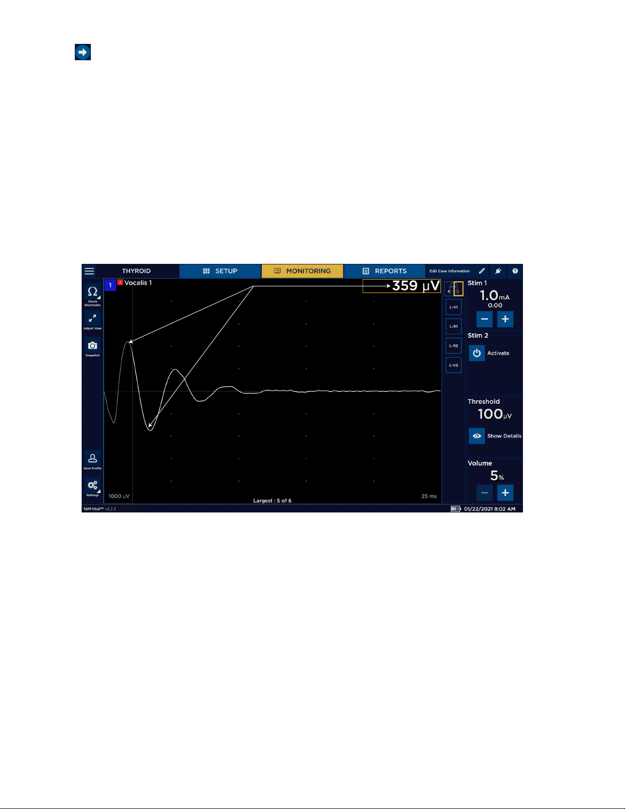
• Upon stimulation of the nerve, EMG is evoked, and the default audible tone is heard at ~4X/sec and raw EMG (thump, thump,
thump). The EMG event is also shown on the monitoring screen as a waveform (gure 1).
Figure 1. Biphasic EMG waveform showing peak-to-peak measurement or amplitude
Note: the latency is measured from the stimulus from the left-hand side of the screen to the start of the EMG waveform.
2. Between probe uses the NIM is passively monitoring muscles and you may hear changes in the EMG, or mechanically evoked
nerve responses that look and sound similar to stimulator evoked nerve responses. Note: The NIM may not alert the surgeon to
all types of surgical manipulation of the nerve including sharp, surgical resection.
3. The surgeon conrms the integrity of the nerve using the probe throughout the entire procedure and at the end of the
procedure. Refer to the table of contents “Audio - understanding what you hear” topic for more information.
Unboxing and installing the system
Check o the contents of the box against the packing slip. If incomplete or damaged, notify customer service at +1 800 874 5797.
If the container is damaged or cushioning material shows stress, notify the carrier and customer service. Keep the shipping materials
for carrier inspection.
After unpacking, save the cartons and packing material. If the NIM Vital™ system is to be shipped, the shipping package will provide
proper protection.
5
Page 8

Nerve Integrity Monitor
Setting up the NIM Vital™ console
1. Remove the NIM Vital™ console from its shipping box.
2. Place the console on a stable counter or on the NIM Vital™ cart (if purchased). Refer to the “Setting up the NIM Vital™ cart” topic
for more information.
3. Install the NIM Vital™ battery that shipped separately from the NIM Vital™ system. Refer to the “Installing the NIM Vital™ battery”
topic for more information.
4. While facing the NIM Vital™ console’s front, gently pull the monitor up and toward you until it reaches the desired placement.
5. Rotate the monitor until the monitor screen is facing you.
6. If you are not using the cart, plug the power cord into the socket on the rear of the console.
Installing the NIM Vital™ battery
1. Remove the two screws on the information plate located on the back of the console base between the patient interface cradles
using a phillips head screwdriver.
2. Insert the battery into the battery compartment with the pull tab on the battery facing up until you feel the battery engage.
3. Replace the information plate by placing the lip on the bottom of the plate into the bottom edge of the battery compartment.
4. Align the two screw holes and replace the phillips head screws using a screwdriver.
Setting up the NIM Vital™ cart
Refer to the “The NIM Vital™ equipment cart” topic for additional information.
1. Remove the cart from its shipping crate. Refer to the uncrating instructions that ship with the shipping crate.
2. At the top of the cart, remove the tape securing the power cord and move it out of the way.
3. Place the NIM Vital™ console onto the top of the cart making sure to align the two pins on the cart with the holes in the bottom
of the console.
4. Reach underneath the console tray and hand-tighten the securing knob.
5. Plug the power cord into the console.
6. Plug the 20 ft Mains power cord into the multi-socket outlet (MSO) located in the lower drawer of the cart.
7. Secure the cord using the cable clamp in the lower drawer using a phillips head screwdriver.
If you plan to add a printer to the bottom shelf of the cart, refer to the “Installing the power isolator” topic. Refer to the “Precautions”
topic for additional information.
Connecting NIM Vital™ accessories
Place the patient interfaces into the cradles to begin charging them.
First time user interface setup
Refer to the “SETUP tab” topic for more information while performing a basic setup.
1. Connect unit to AC power.
2. Turn power switch On.
3. After the system completes the self-test, press .
4. Select Language (English is default).
5. Press or to close Global settings.
Set the time zone, date, time, and date/time format
1. During setup, press time/date in the lower right corner of the screen.
The System Date Time Settings dialog box appears.
2. Select the time zone from the Time Zone drop-down menu.
3. Select the date/time format using the Date Time Format drop-down list.
4. Press and select the correct date from the calendar.
5. Select the time using the Hours/Minutes/Seconds drop-down lists.
6. Do one of the following:
• Press [Conrm] and the system saves the information.
• Press [Cancel] to exit without saving the information.
6
Page 9

Nerve Integrity Monitor
Create a surgeon prole
You can create a Surgeon prole from the Select Prole screen.
1. Click [NEW] on the initial setup screen.
The New Surgeon Prole dialog box appears.
2. Press the Enter Prole Name text box.
The electronic keyboard appears.
3. Type the name of the Surgeon prole.
4. Click [CONFIRM].
The Edit Prole screen appears.
5. Select a procedure(s) from the Available Procedures lists using the tabs to navigate between specialties.
6. Click to move the procedures to the Prole Procedures box.
7. Once the user moves the procedure, she/he can rename the procedure by:
• Select the procedure to rename from the Prole Procedures box.
• Press . The Edit Procedure Name dialog box appears.
• Type the new procedure name.
• Click [Conrm] or [Cancel] to either conrm the name change or cancel the change.
8. Click [Conrm] to save the surgeon prole.
9. Do one of the following:
• Select the prole to continue with the new prole.
• Press [Edit], then select the new prole to return to the Edit Prole screen and modify the prole.
• Select [Delete], then select a prole and press [CONFIRM] or [CANCEL] to either conrm the removal of the prole or cancel
the removal.
Saving to a surgeon prole
Once the user creates a surgeon prole and selects a procedure, the user can save the settings changes made during monitoring
into the prole’s procedure as preferences. Refer to the “Create a surgeon prole” and “Select a user prole” topics for additional
information.
1. On the Monitoring screen, press .
2. After making changes, press to save all current changes.
The system removes the save prole button once the system saves the settings until the next time
the user changes settings. The next time the user selects the procedure from the surgeon prole, an asterisks appears next
to its name to indicate it has been customized and loads with all of the saved surgeon preferences. Note: This procedure does
not save patient case information.
Save custom proles to a USB drive
1. Navigate to the Prole Selection screen.
2. Insert a USB drive.
The system detects the USB drive and appears.
3. Click the button.
The system saves all custom proles.
Import custom proles from a USB drive
1. Navigate to the Prole Selection screen.
2. Insert USB drive containing saved custom proles.
The system detects the USB drive and appears.
3. Click the button.
The system saves all the custom proles on the console. Refer to the “Select a user prole “ topic for additional information.
7
Page 10
Nerve Integrity Monitor
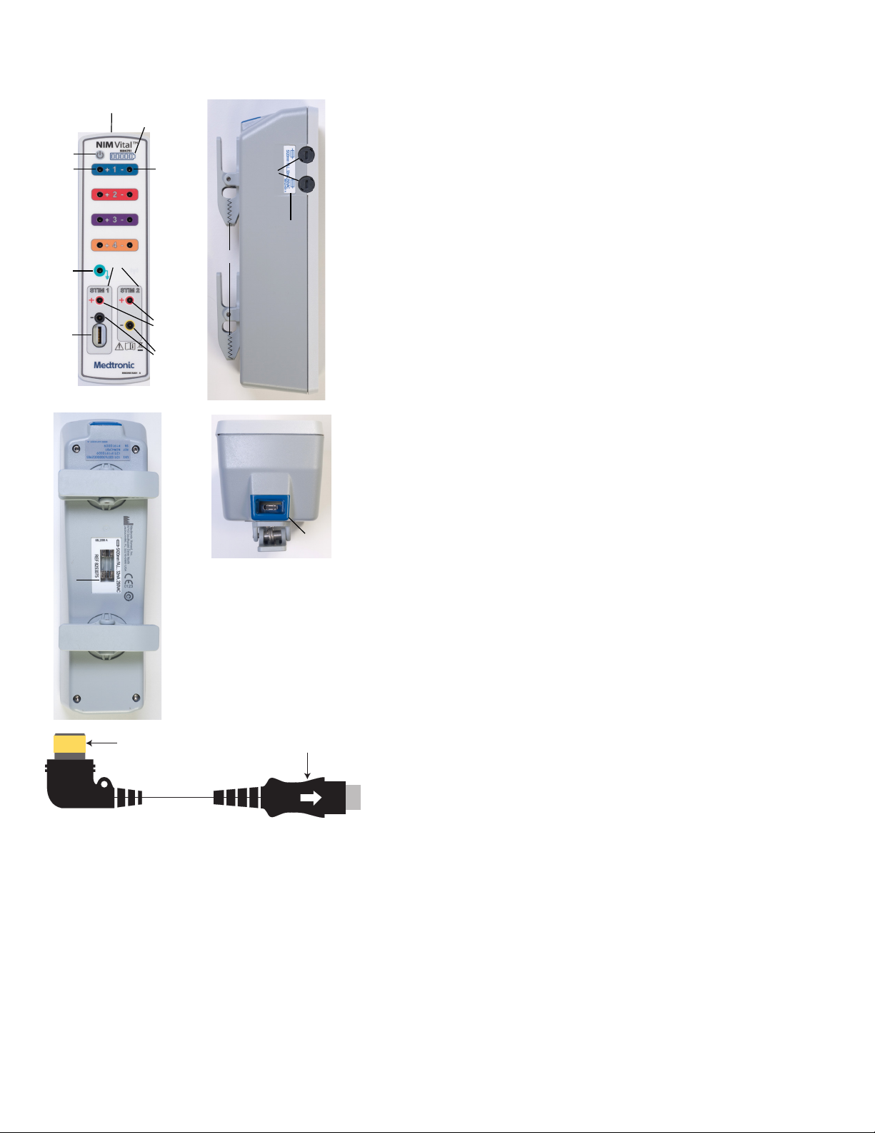
Components
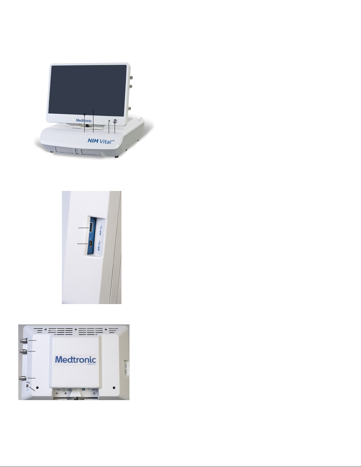
Console front
1 Power button.
2 Screen.
3 Camera.
4 Microphone.
3
2
1
4
Console left side
1 USB-A (3.0) port.
2 USB-C (3.0) port.
1
2
Console right side
1 STIM 1 adjustment knob.
1
2 STIM 2 adjustment knob.
3 Volume knob.
2
3
4
4 Mute detector adaptor connection.
8
Page 11
Nerve Integrity Monitor
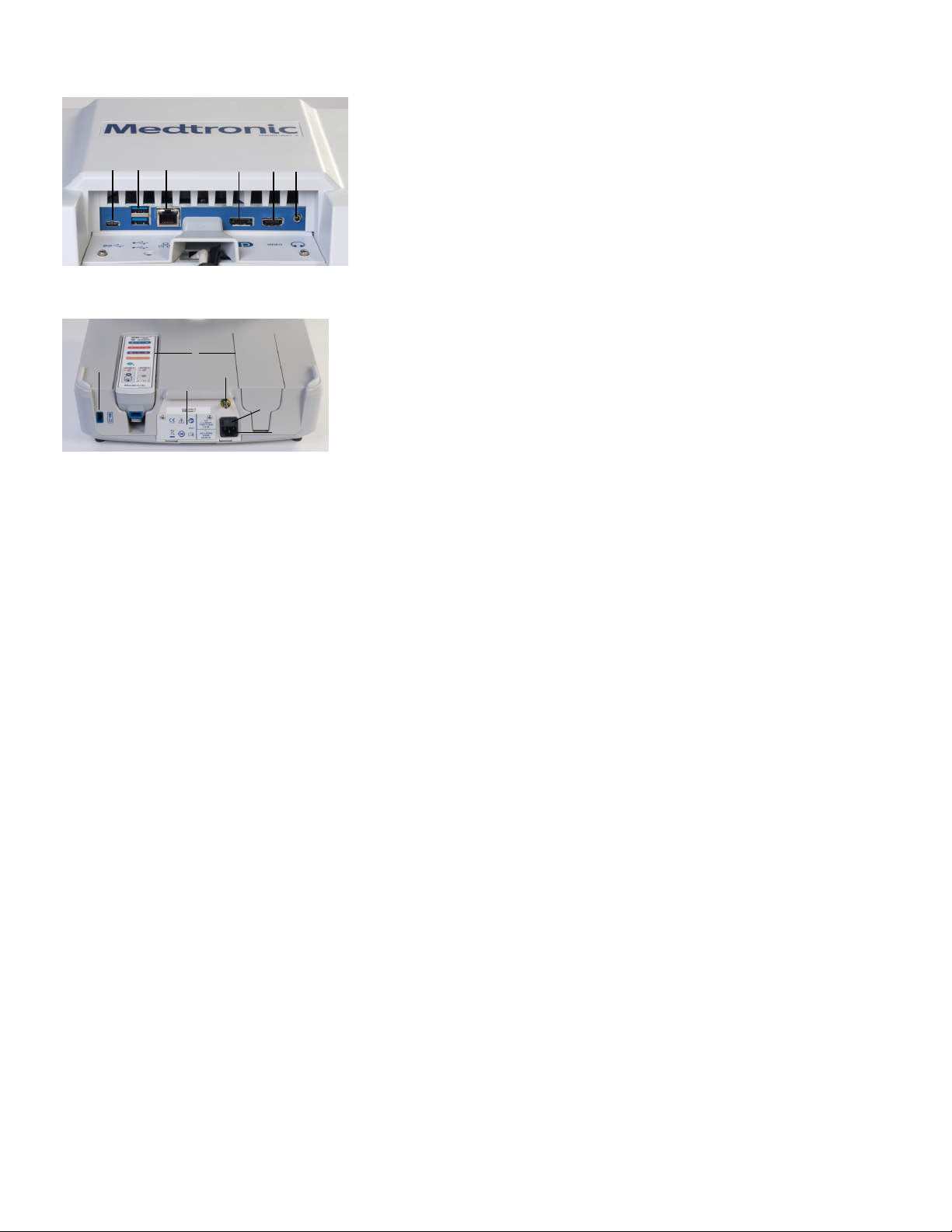
Console display bottom
1 USB-C.
2 Dual USB-A.
2
1
3
5 6
4
3 Ethernet.
4 Display port.
5 HDMI. Not specically for use with a microscope.
6 Audio (headphones).
Console base back
1 Patient interface docking cradles.
2
1
4
3
6
5
2 Wired patient interface port.
3 Battery door.
4 Earth ground (P.O.A.G.).
5 Power inlet.
6 Console fuses.
9
Page 12
Nerve Integrity Monitor
Patient Interface
1 Electrode ground. Signal return for patient electrodes.
11
12
2 Stimulating Instrument Jack or Stimulator Probes (Monopolar or
Bipolar).
14
8 9
7
3 Incrementing Probe Control Jack. Connects Incrementing Probe controls
to the NIM Vital™.
4 Stimulus (out) Jack, negative (-).
13
5 Stimulus Return, positive (+).
6 Patient Interface to console connector.
1
2
10
7 The Patient Interface fuses are for Stimulator Output and specically
tested for ECU protection.
8 Positive Electrode Jacks. Positive electrodes have matching color-coded
3
5
4
wires and plugs.
9 Negative Electrode Jacks. Negative electrodes have black wires and
color-coded plugs.
10 Patient Interface Clips.
11 Docking connector.
12 Battery indicator LED.
13 Fuse indicator LED.
14 Power button.
15 Spare fuses.
6
15
Incrementing Probe Adapter
2
1
1 Connect to Incrementing probe.
2 Connect to patient interface.
Note: For use with prass incrementing probe (CFN 8225825 and CFN
8225490)
10
Page 13
Nerve Integrity Monitor
Incrementing probe
The (single use) incrementing probe provides the surgeon with the means to adjust the stimulation current at the surgical site. Refer
to the “Probe-based functions” for additional information on specic button functions.
2 3
1
1. Toggle button normal or at rest.
2. Increase.
3. Decrease.
4. The user can perform the following functions with the toggle button:
• Momentary press saves the current screen to memory (for reports) and to a selected peripheral device (printer and/or USB
ash drive) if the user selected that option in the settings area.
• Press and hold opens a menu on the user interface with more options.
4
Power Cords
1895825 Power Cord, 6 Meter, EU
1897821 Power Cord, 6 Meter Standard, U.S.
1895824 Power Cord, 6 Meter, U.K.
1895823 Power Cord, Japan, 100 V
Software overview
Turning the system on
1. Press .
The splash screen appears and automatically performs an internal integrity check. Once the system completes its integrity check,
the Select Prole screen appears.
The system automatically performs an internal integrity check on the system and batteries for the console and patient interface, if
docked, each time you turn the NIM Vital™ system ON. If the system encounters any errors during the self-test, the user will not be
able to use the NIM Vital™ system. Refer to the “Maintenance schedule” and “Troubleshooting” topics for more information.
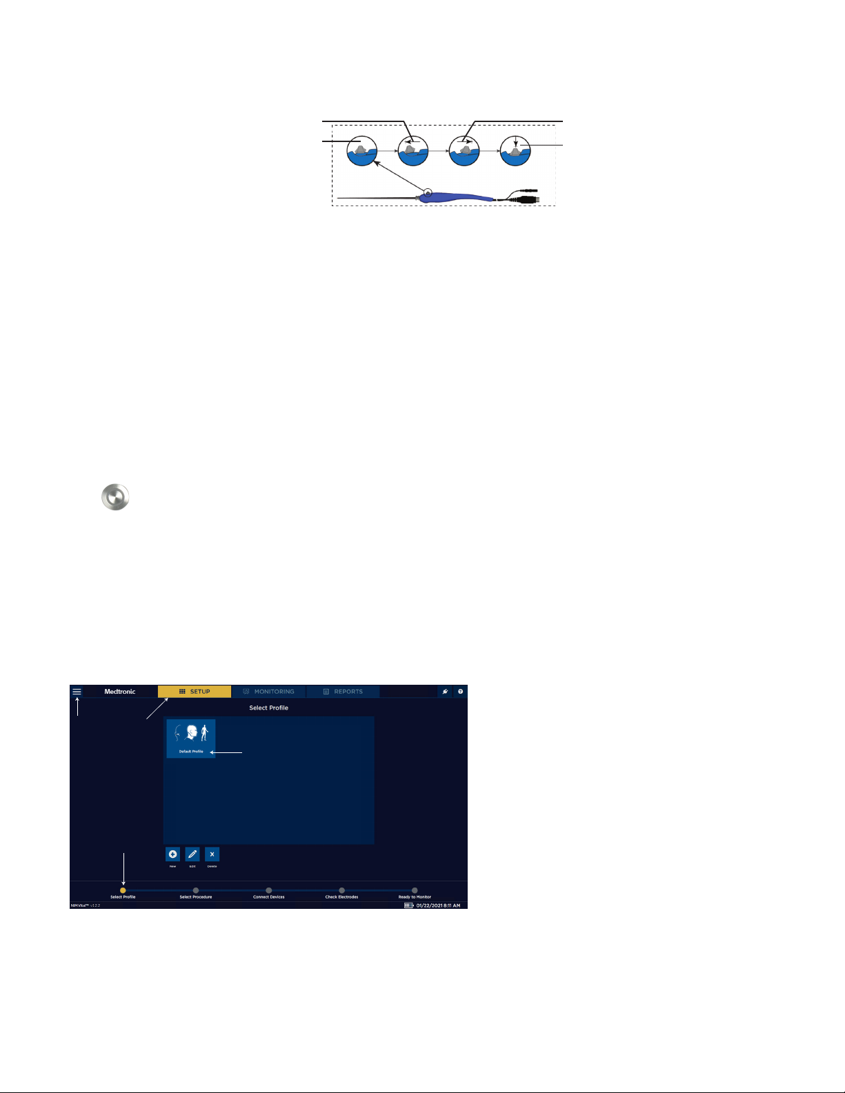
SETUP tab
The setup tab consists of the following screens:
Screen 1. Select Prole 1 Global settings.
2 SETUP tab.
1
2
3
4
3 Prole options.
4 Progress tracking bar.
11
Page 14
Nerve Integrity Monitor
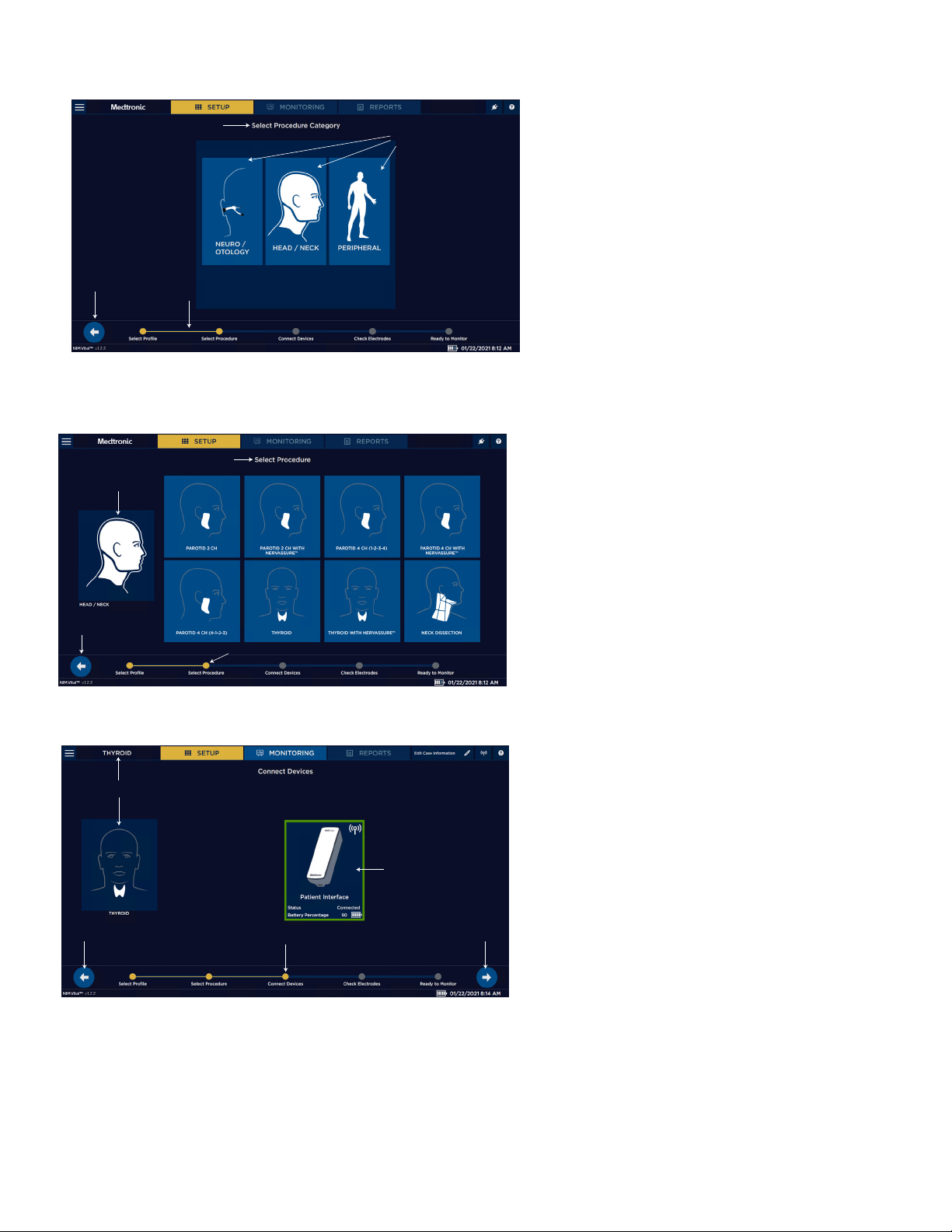
Screen 2. Select Category 1 Select Procedure Category (if the user selected
the default prole on the previous screen).
1
2
2 Specialties.
3 Progress tracking bar.
4 Return to previous screen.
4
3
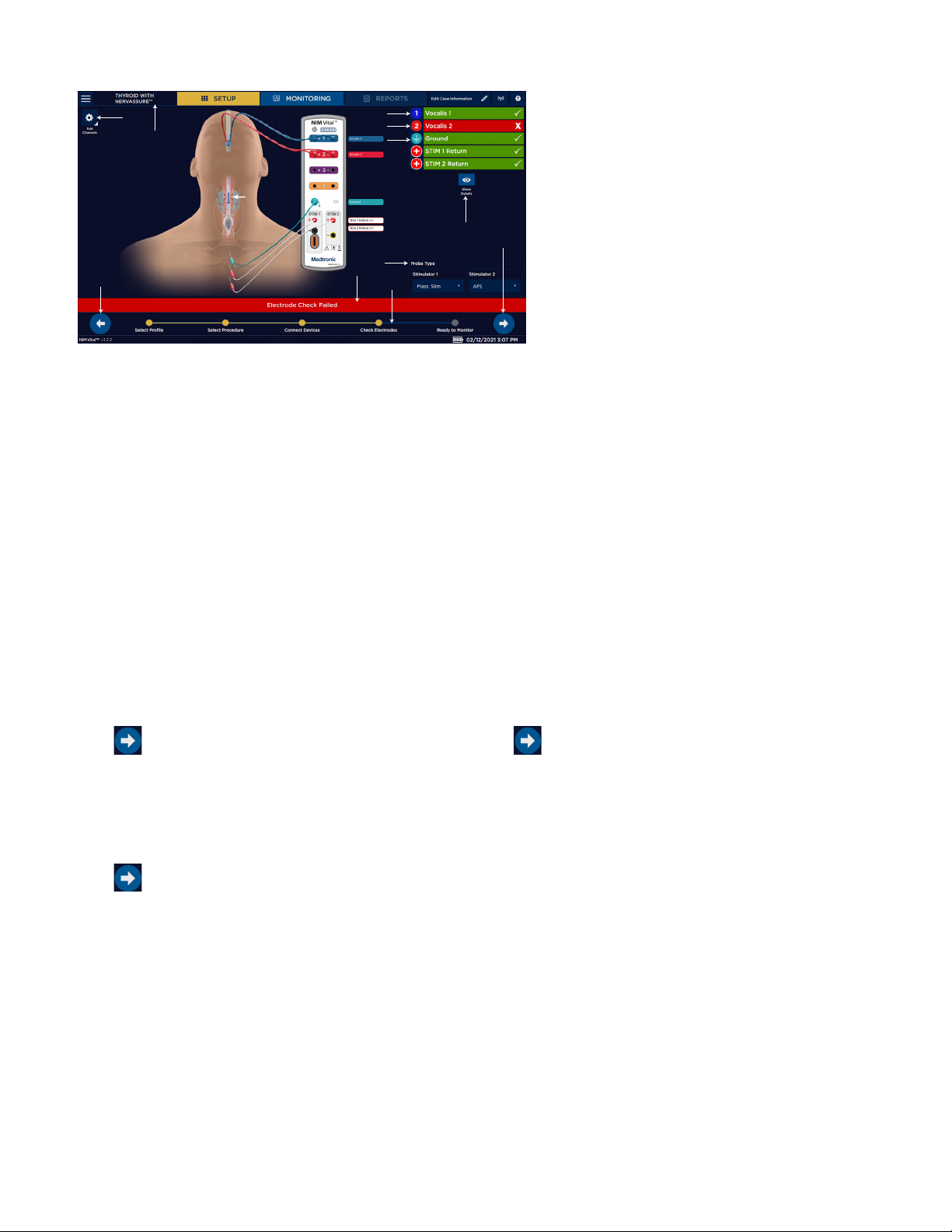
Screen 3. Select Procedure 1 Go back.
2 Selected category.
3
2
1
4
3 Select procedure.
4 Progress tracking bar.
Screen 4. Connect Devices 1 Go back to previous setup screen.
2 Selected procedure.
3 Go to next setup screen.
2
4 Status of the patient interface (connected).
5 Progress tracking bar.
12
4
1
5
3
Page 15
Nerve Integrity Monitor
Screen 5. Electrode Check
1
3
4
5
6
1 Edit Channels.
2 Go back to previous setup screen.
3 Selected procedure.
4 Channel 1 electrode check passed.
5 Channel 2 electrode check failed.
6 Ground check passed.
7
11
8
2
9
10
7 Electrode check show/hide details.
8 Stim probe selection.
9 Electrode check status bar.
10 Progress Tracking bar.
11 Proceed to monitoring.
Select user proles or default categories
The SETUP screen appears after the system has completed an internal integrity check via the splash screen.
Select a default procedure
During the setup, you can keep track of the progress of setting up the default procedure using the yellow indicator bar at the
bottom of the screen.
1. Press [Default Prole] on the touchscreen.
The system progresses to the next screen showing the default categories.
2. Select a default category.
3. Press one of the pre-dened procedures on the touchscreen.
The “Connect Devices” screen appears.
4. Undock the patient interface. If no patient interface is docked, dock one to register it with the NIM Vital™ system, then undock it.
The system automatically begins connecting the patient interface. The Status: Connected message appears with a green border
around the Patient Interface selection box and the paired blue wireless symbol illuminates on the patient interface.
Note: If a wireless connection is not available, plug in the patient interface cable between the NIM Vital™ console and the patient
interface. The console connector is located on the back, left side and is marked by a PI box symbol (refer to the “Buttons and
indicators” and “Symbols” topics for more information).
5. Press on the bottom right side of the screen. Note: if you press without connecting to a patient interface (wired
or wirelessly), the Notication dialog box appears with the message, “Monitoring is unavailable until the patient interface is
connected. Continue?” The user must select [CONFIRM] or [CANCEL] before proceeding to the next screen.
The Check Electrode screen appears and shows the status of the electrode check.
6. Place the electrodes on the patient according to the diagram. Refer to the “Help” topic for additional information.
7. Select the correct stimulator for the procedure.
8. Press on the right of the screen, or the MONITORING tab, to progress to the MONITORING screen.
Note: If you progress to the MONITORING screen without passing the electrode check, the warning message, “Impedance check
has failed: Continue?” appears. The user must select [CONFIRM] or [CANCEL] before proceeding to the MONITORING screen.
Select a user prole
During the initial setup, you can keep track of the progress of setting up the default procedure using the yellow indicator bar at the
bottom of the screen.
1. Select a pre-dened user prole. Refer to the “Create a surgeon prole” topic for additional information.
2. Press one of the pre-dened procedures on the touchscreen.
The Connect Devices screen appears. Refer to the “Connect Devices” topic for more information.
13
Page 16

Nerve Integrity Monitor
3. Undock the patient interface.
The system automatically begins connecting the patient interface. The Status: Connected message appears with a green border
surrounding the Patient Interface selection box and the paired blue wireless symbol illuminates on the patient interface.
Note: If a wireless connection is not available, plug in the patient interface cable between the NIM Vital™ console and the
patient interface. The console connector is located on the back, left side and is marked by a patient interface symbol (refer to the
“Buttons and indicators” and “Symbols” topics for more information).
4. Press on the bottom right of the screen.
The Check Electrode screen appears and shows the status of the electrode check. Refer to the “Check Electrode screen” topic for
additional information.
5. Place the electrodes according to the diagram. Refer to the “Electrode placement” topic for additional information.
6. Select the correct stimulator for the procedure.
7. Press on the bottom right of the screen, or the MONITORING tab, to progress to the MONITORING screen.
Note: If you progress to the MONITORING screen without passing the electrode check, the warning message, “Impedance check
has failed: Continue?” appears. The user must select [CONFIRM] or [CANCEL] before proceeding to the MONITORING screen.
The Monitoring screen appears.
Connect Devices screen
The following information is located on the Connect Devices screen.
The symbol appears in the top right-hand corner of the screen when the patient interface is cradled.
Wireless connection
Undocking the patient interface initiates an automatic wireless connection to the console. The Status: Connected message appears
with a green border around the Connect device box and the paired light will illuminate on the patient interface.
The symbol appears in the top right-hand corner of the screen when the patient interface is connected wirelessly.
Note: Only undock the patient interface you plan to use. Once undocked, the system automatically connects to the patient interface
that is undocked rst. If you need to switch connection to the other patient interface, replace the rst patient interface into its dock
and undock the other patient interface box.
Wired connection
If a wireless connection is not available, plug in the patient interface cable between the NIM Vital™ console and the patient interface.
The console connector is located on the back-left side and is marked by a patient interface symbol (refer to the “Buttons and
indicators” and “Symbols” topics for more information).
The symbol appears in the top right-hand corner of the screen when the patient interface is connected with a cable.
Check Electrode screen
The Check Electrode screen assists you with electrode placement.
The surgeon should insert the electrodes into the appropriate target muscle location innervated by the monitored nerve. The
surgeon should then insert the ground electrode (green) and the stim return (white) as shown in the electrode placement diagram.
Once the surgeon places the electrodes on the patient, the surgeon needs to insert the other end of the electrodes into the patient
interface to complete the electrode setup. NIM Vital™ systems include nerve and electrode placement guides that are color-coded to
help reduce confusion.
The electrode placement guide contains some, but not all, possible electrode placements. Press on the SETUP screen for an
additional list of electrode placement guides ( Refer to the help section for electrode placement diagrams).
When the system runs an electrode check, this screen shows the electrodes the system is testing.
• Green bar with white check marks indicate the electrode is connected to the corresponding channel.
• Red bar with white Xs indicate the connection is incomplete.
• A spinning icon indicates the system is calculating.
If you connected all the electrodes properly, all channels will have green check marks indicating the electrode check has passed.
Select the correct stimulator for the procedure and then press to proceed to monitoring.
STIM 1, STIM 2, Ground - If a spinning icon appears after the system has completed the test, no channel electrode or ground was
connected, so the system reads that as a no value (impedance). You must connect at least one channel electrode and ground for the
system to read STIM 1, STIM 2, and ground impedance.
14
Page 17
Nerve Integrity Monitor
If the user needs detailed values, press to show the more detailed impedance menu. If showing details, use the drop-down
menus on the Electrode Type panel (the only screen where you can adjust the electrode type in use) to select the type of electrode
you want to use. Refer to the “Troubleshooting” topic for information on electrode troubleshooting.
Note:
• You can bypass the next place electrodes screen by selecting the MONITORING tab or .
• If you bypass the Check Electrode screen, no pre-surgery impedance values of the electrodes, ground, or STIMreturns are
available for printed/saved reports.
• If the patient interface, electrodes, ground, or STIMreturns were disconnected when you exit the Check Electrode screen, any
printed reports will show a failure of the impedance values of the disconnected item(s).
• There is no STIM status (blank) if you select Bipolar on the Probe Type (located in the Settings/Stimulation Panel).
• STIM2 appears after you turn it on using the Activate button located on the main screen, or by selecting the STIM2 from the
drop-down list on the Stimulation Panel.
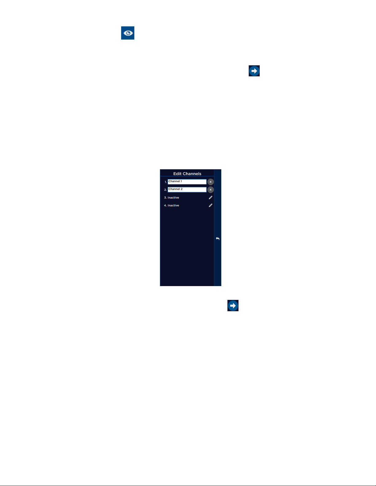
Edit channel names
From the Electrode Check page, the user can open the Edit Channels panel. This panel enables adding, editing, and removing
channels from the selected procedure. Once changes have been made, select [Apply Changes] to use the settings in the current
procedure only, or select [Save to Prole] to save the channels for current and future use. The user can also reset changes to the
latest save point (or to default in a default procedure) by selecting [Reset to Saved].
MONITORING tab
Access the MONITORING screen by pressing MONITORING on the top tool bar, or .
The main monitoring screen helps provide EMG information to the surgeons. The EMG information can be free running and
stimulation evoked.
EMG Display
Free-running EMG
If the user has Event Capture disabled on the Threshold panel, the NIM Vital™ system continuously displays free running EMG picked
up by the electrodes. If the user enables Event Capture, the system only displays values above the threshold values.
Evoked EMG
The surgeon can use the stimulator probe to conrm the location and integrity of the nerves. When the surgeon touches the surgical
site with the STIM probes, one of the two following events happen:
You can expect one of two events:
• Stimulation with an EMG response - This event occurs when the stimulation device touches healthy nerve tissue that is capable
of propagating an action potential that reaches its innervated muscle tissue. The surgeon will notice the following on the
console:
— Audio (thump, thump, thump, thump)
— Biphasic wave form
— An amplitude value
— A STIM measured value
15
Page 18
Nerve Integrity Monitor
• Stimulation of tissue, but no EMG response - This event occurs when the stimulation device touches non-nerve tissue, or if the
current delivered is not sucient to propagate an action potential. The surgeon will notice the following on the console:
— Hear the current delivery tone
— See a STIM measured value
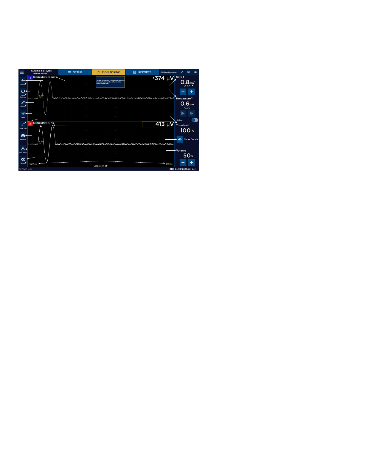
A detailed list and explanations of all the monitoring screen buttons are displayed below.
1 Scale. Displays screen scale settings.
10
9
11
12
13
14
2 Settings button.
3 Save Prole button (only when settings have been
changed, but not saved into a prole).
8
7
5
4
6
15
16
4 Trace. Display stimulus nerve activity/inactivity.
5 Adjust view.
6 Snapshot button.
7 Freeze button (when activated).
8 Measure button (when activated).
3
2
1
17
9 Check Electrodes button.
10 Baseline button (only active if the user activates it
on the settings panel).
11 Channel label. Displays the channel number and
nerve being monitored.
12 Amplitude.
13 Stim panels.
14 Stim return value.
15 Threshold panel.
16 Show details button. Provides access to event
capture and adjust threshold.
17 Volume panel. Adjust the system volume.
EMG display area
The amplitude displays activity level in microvolts on each channel:
• A box encloses the activity level of the highest channel.
• When the STIM probe is removed and “Largest Overall” is selected, a box encloses the channel with the largest event.
• If the system detects a signal (response) outside the range of the system’s ability to measure (100,000 V or higher), the system
displays the “Out of Measurement Range” message.
• Absolute Amplitude Limit: The Absolute Amplitude Limit (in uV) and the Amplitude Percentage Limit (in %) are used in
conjunction to determine the APS amplitude alarm criteria. The lower of the two limits sets the alarm limit. For example, if the
baseline amplitude is 2000 V, Amplitude Percentage limit is 50%, and Absolute Amplitude limit is 500 V, then a signal of 800
V would not cause an alarm because although the signal has decreased more than 50%, it is still above the Absolute Amplitude
limit.
Recognizing stimulus artifacts
Stimulus artifact is a monitoring term for an artifact created by stimulus voltage delivered to the patient, which is picked up as
feedback either internally or externally to the monitoring equipment. It is normally small and does not impact monitoring but can,
under certain conditions, be displayed and sounded on the monitor. It is important to understand the NIM system’s visual and audio
feedback so as not to confuse the stimulus artifact with real EMG, or recognize if both the stimulus artifact and real EMG are present
at the same time.
The on-screen stimulus artifact, when it appears on the monitoring panel display, is seen as an event (above or below threshold)
which starts directly after the stimulus on the left side of the screen and proceeds for a duration into the EMG waveform detection
area. The level of the artifact is directly proportional to the stimulus delivery and cannot be EMG because nerve signals need time
propagate.
The stimulus artifact sound is the audio representation of stimulus artifact. It is a high frequency sound similar to cymbals and
sounds like “ti - - tchi.” It is unlike an EMG sound which is similar to a drum sound.
16
Page 19
Nerve Integrity Monitor
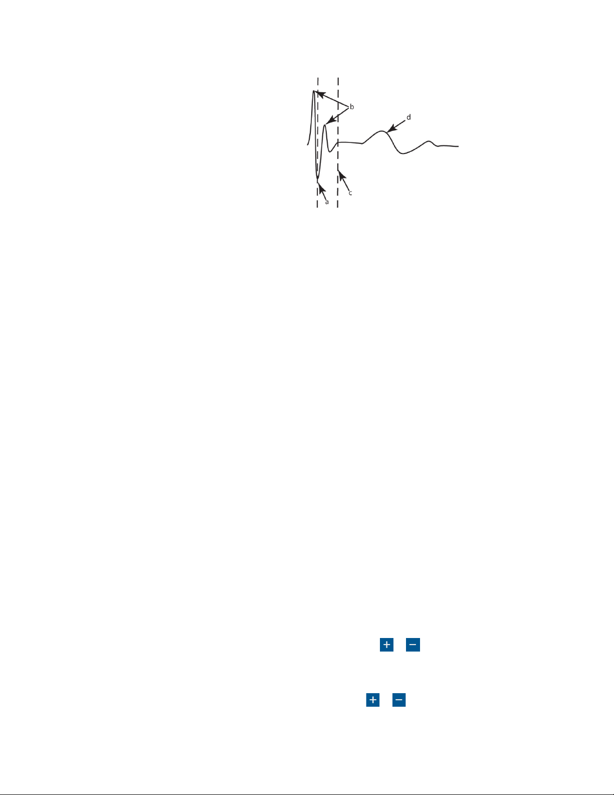
The stimulus rejection period enables you to lter the stimulus artifact (electric noise caused by stimulation) and all other signals in
this period.
a. Original Rejection Period setting.
b. Stimulus Artifact.
c. Move Rejection Period line to here to avoid artifact.
d. EMG Response.
Understanding and recognizing other artifacts
The NIM Vital™ system features sophisticated artifact rejection technology designed to provide highly sensitive and accurate
monitoring. However, there may be electrically generated signals in the range of true response that the NIM Vital™ system cannot
dierentiate. Refer to the “Troubleshooting” topic for more information.
Examples:
• A transcutaneous stimulator used by the anesthesiologist might generate an audible signal.
• Any external nerve locator/stimulator may not provide automatic synchronized muting with the NIM Vital™ system.
• Electrical leakage from faulty thermal cautery units. You can identify the spurious signals by their lack of surgical context (there
was nothing the surgeon was doing at that moment that could have caused a true EMG response).
• If the recording electrodes and the stimulator (+) or (-) cables become tangled the resulting stimulus artifact might be spuriously
detected as an EMG event. Be careful to route the recording electrodes away from stimulator cables.
• If/when wires must cross, they should cross at right angles. Never run other operating room cords/cables parallel to any of the
NIM Vital™ system wires.
• The pace pulse generated by pacemakers may be detected and displayed by the NIM Vital™ system as a rhythmic artifact signal.
This is caused by the electrode ground or stimulus return electrodes being in close proximity to the pacemaker or its lead wire(s).
The artifact caused by the pacemaker may be reduced by repositioning the Electrode Ground and Stimulus Return electrodes to
the top of the patient’s shoulder (the Acromion) (use shoulder opposite operative side). The Electrode Ground (green plug green
wire) and Stimulus Return (red plug white wire) electrodes should be positioned about 5 cm apart, green Proximal, red Distal.
Once the electrodes are repositioned, verify that the Stimulus Return and Ground Impedances are within tolerance (review Setup
Mode/Electrode Check ).
• There may also be interference-generated signals in the range of true response that the NIM Vital™ system cannot dierentiate.
An example of this type of artifact signal could occur when the surgeon strikes two metal instruments together within the
surgical eld, such as a metal suction tube with a dissecting tool. Such signals are typically monophasic with fast onset and
oset. That is, the signals appear on the screen as sharply peaked responses in one direction only.
• While these artifacts are signicantly dierent in waveform appearance from true EMG events (which have a biphasic waveform),
the magnitudes of these signals can reach several hundred microvolts causing the event tone to sound. However, the surgeon is
usually aware when two instruments have been struck together and can, therefore, relate such “false positive” responses to the
surgical context.
MONITORING tab right panel
STIM 1
The STIM1 panel displays the following settings:
• Stimulation setting (large numbers in mA units)
• Measured value (small numbers)
• Adjustment buttons for the STIM1 current settings.
• You can adjust the current of the stimulator plugged into the STIM 1 port using or , or the knobs located on the side of the
monitor. Refer to the “Stimulation panel” topic for more information.
STIM 2
If the STIM2 panel is inactive, it displays the Activate button. If active as a second stimulator, its display is the same as STIM1.
You can adjust the current of the stimulator plugged into the STIM 2 port using or , or the knobs located on the side of the
monitor. Refer to the “Stimulation panel” topic for additional information.
17
Page 20
Nerve Integrity Monitor
Threshold
Use threshold to dene where EMG activity becomes signicant. EMG activity exceeding the threshold is dened as an event and
results in event tones. Any activity below this threshold does not trigger an audible event.
Show details/event capture
The Threshold panel displays the threshold settings and enables you to adjust the setting level (in 5, 10, or 100V increments
depending on the Threshold value). Press to access the threshold settings and then press or to increase or decrease the
value as desired. The system displays the setting in micro-Volts. Press to access the Event Capture toggle button. When event
capture is enabled, the system captures any waveform above the event threshold. The event capture stays on the screen until the
next waveform above the threshold appears.
Volume
The Volume panel displays an adjustable volume setting.
You can adjust sound levels using or in 5% increments. The default setting is 50.
MONITORING tab left panel
The NIM Vital™ left panel contains the following items you can use to adjust the monitoring screen.
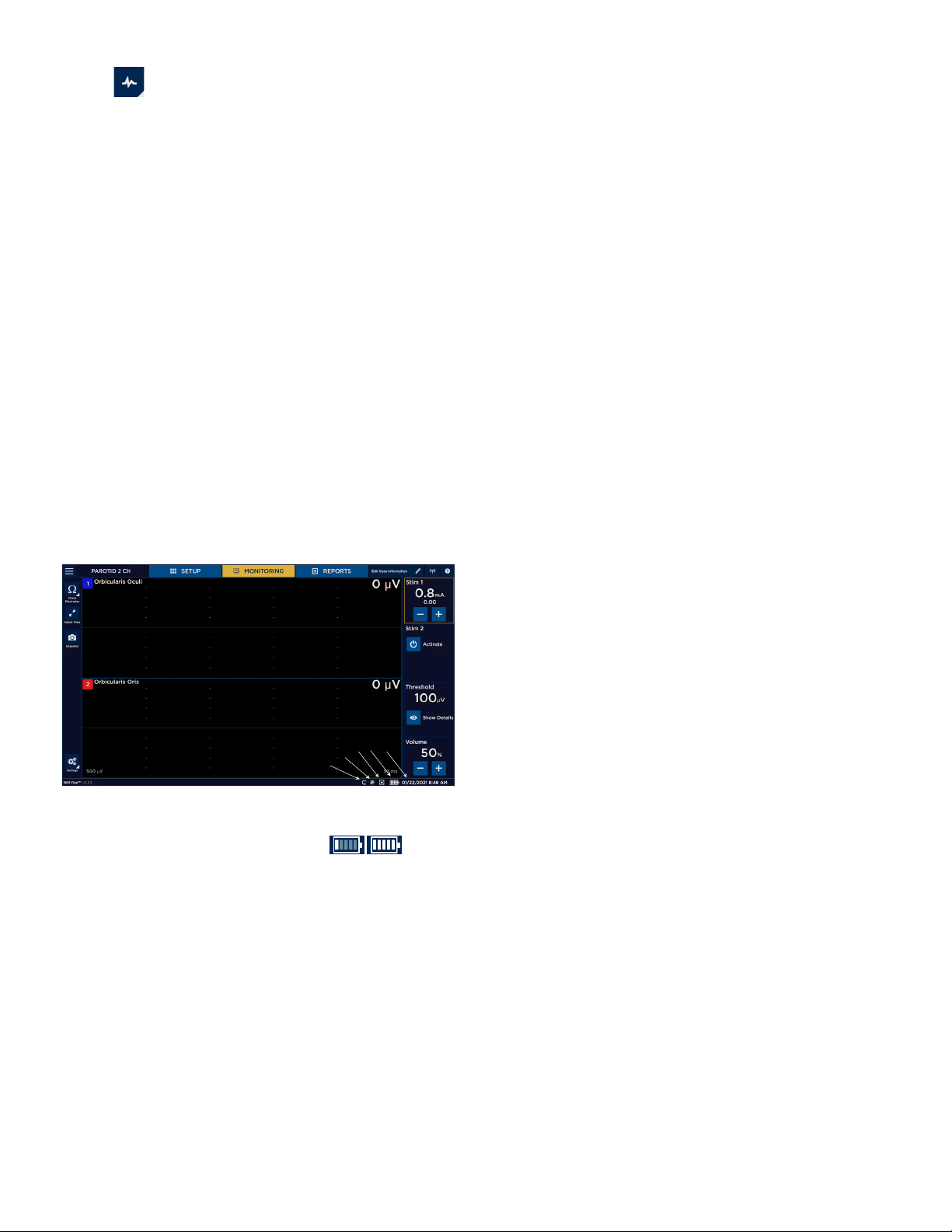
Baseline
You can create a baseline and then manually trend future stimulations against the baseline using the trend function. For
Nervassure™ continuous monitoring, select a Nervassure™ procedure on the Select Procedure screen during initial setup. For nonNervassure™ procedures, you can use the NerveTrend™ function which works similarly to the trend function.
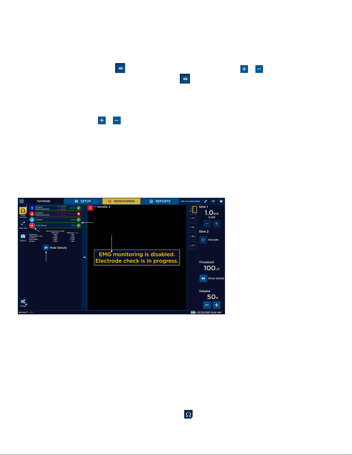
Electrode Check button
The Electrode Check panel checks the integrity of the patient to the patient interface connections.
1
1 Electrode check button. Opens/
closes Electrode Check panel.
2 STIM1, STIM2, and Ground status
3
2
4
elds.
3 Electrode Show Details status eld:
• Green check marks. Green
check marks appear when
the electrodes are connected
5
correctly.
• Spinning icons. Spinning
icons appear while the
system runs the electrode
test.
• Red X. A red X appears when
the electrodes are connected
incorrectly or fail.
4 The system disables monitoring
when the Electrode Check panel is
open.
5 Show/hide details button.
Note:
• There is no STIM status (blank) if you select Bipolar on the Type Panel
(located in the Advanced Settings/Stimulation Panel).
• There is no STIM2 status (blank) if a single stimulator is connected.
• STIM 1, STIM 2, Ground - If a spinning icon a question mark appears after the system has completed the test, no channel
electrode or ground was connected, so the system reads that as a no value (impedance). You must connect at least one
channel electrode and ground for the system to read STIM 1, STIM 2, and ground impedance.
Electrode check
You can perform an electrode check on the MONITORING screen using .
18
Page 21

Nerve Integrity Monitor
Electrode Check panel pass/fail
The system measures impedance values of the electrodes to the patient to conrm the integrity of the connection. The electrode
check only indicates that the electrodes are making contact with the patient’s tissue. The system does not conrm that the needle is
inserted into the correct muscle. The user is responsible for ensuring the electrodes are placed, or inserted into the target muscles.
The above graphic illustrates that all channels have passed the electrode check. A red bar with a white X will replace the green bar
with a white checkmark if a channel(s) fails.
Electrode Check Show Details button
Press the Show Details button to see the actual impedance values. Refer to the “Troubleshooting” topic for more information.
Note: When you select , the system displays the normal electrode impedance limits if the number of channels is less than six.
Measure
When activated, press to enable and adjust the measurement cursor. Refer to the “Display settings” topic for additional
information.
1. Enable the Measurement cursor on the main screen.
2. Select the cursor type. This determines where the cursor is initially displayed.
3. Adjust the cursor position.
Freeze
When activated, press to freeze the current waveform on the screen. The main screen shows “Display is Frozen” during this
time. Press again to end the freeze. Monitoring continues in the background when enabled and monitoring sounds still play.
19
Page 22
Nerve Integrity Monitor
Adjust view
Press to adjust the scale (Y-axis V [amplitude] and x-axis mS [milli-seconds]).
1 Adjust View button.
2 The vertical portion of the EMG display represents
peak-to-peak amplitude. You can adjust the scale.
The vertical screen is divided into equal sections per
1
channel with 1/2 of each channel positive and 1/2
negative. Each channel is separated by a solid blue
line.
3 Time scale is represented by the horizontal portion
of the EMG display and is adjustable. The screen is
divided into equal sections. This diers from the
“Amplitude scale” in that the “Time scale” selection is
2
3
the entire horizontal portion of the screen.
Note: Changing either scale only aects how the
data appears on the screen. It does not modify the
sensitivity of the unit.
Snapshot
Use the Snapshot Button to save the current screen to memory (for reports). Based on options selected in Settings/Display, taking a
snapshot can also ask for additional comments, print, and/or save to le on a connected USB.
Save Prole
Press [Save Prole] to save any current settings changes to a user prole. If the user is in a default prole pressing [Save Prole]
asks the user to enter a new prole name and automatically adds the procedure to the prole. If the user is in a custom prole
pressing [Save Prole] updates existing stored procedure settings.
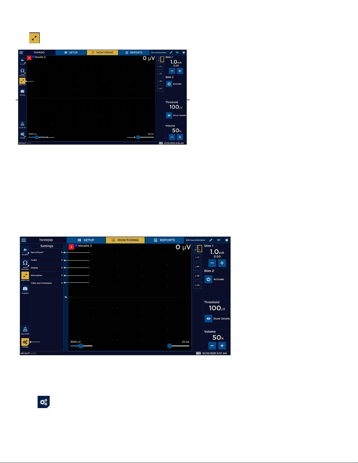
Settings
Use the Settings panel to access additional settings/advanced settings and monitoring features.
1 Settings button.
5
4
3
2
6
2 Stimulation settings.
3 Display settings.
4 Audio settings.
5 NerveTrend™ or Nervassure™
settings (if enabled).
6 Titles and Comments.
1
NerveTrend™ (available once enabled)
NerveTrend™ enables users to manually track the status of a nerve over time. The system records EMG responses that the user
captures and plots over time using a graph.
Creating a NerveTrend™ baseline
1. Press .
2. Select Display.
3. Expand Additional Features.
4. Toggle Enable NerveTrend™ to On.
20
Page 23
Nerve Integrity Monitor
5. Press .
The NIM Vital™ system performs a number of measurements (minimum of 20) and shows the results for channels one and/or two
with the amplitude and latency (if enabled).
6. Do one of the following:
• Press [Cancel] to return to MONITORING without creating a baseline measurement.
• Press [Re-evaluate] to direct the system to restart the baseline measurement.
• Press [Continue] to use the system’s measurements.
If you pressed (insert continue button), the Operating Side panel appears.
7. Select an operating side which auto-generates as session title.
8. Change the session title or add session comments, if desired.
9. Press [Accept].
Using the NerveTrend™ feature
1. Identify a proximal location on the nerve at risk.
2. Stimulate the nerve at the proximal location using the supramaximal stimulus value.
3. Initiate a NerveTrend™ baseline. Refer to the “Probe-based functions” and “NerveTrend™” topics for additional information.
4. After a successful baseline acquisition, stimulate the same anatomical location at the same stimulus intensity and document the
EMG response on the graph using the incrementing probe buttons or the Trend button on the NIM Vital™ system (stimulation
at a modied intensity causes responses to appear as grey indicating that they cannot be graphed. Returning the stimulation
intensity to the baseline level and repeating stimulation allows graphing to continue).
Note: the user can repeat this step multiple times throughout the procedure to visualize a change in the nerve function.
NIM Vital™ bottom panel
The bottom panel of the NIM Vital™ displays the following informational symbols.
1 Data recording (on).
2 System is running on console battery (or No Mains power
connected).
3 Take a screenshot.
4 Patient interface battery status.
5 Date/time (settings if in Setup).
4 5
3
2
1
Battery status
The user can view the battery status using . The battery indicator enables the user to see the remaining battery in the
Patient Interface. A lightning bolt icon appears on the bottom right of the display when the battery is charging.
Recording icon
If the user has enabled data recording, the recording icon appears on the bottom panel until the user turns o the setting.
Console battery icon
The console battery icon slowly pulses when the console detects that it has lost main A/C power. It remains until the console detects
it has regained A/C power.
Screenshot icon
The screenshot icon appears when the console detects a mounted, approved USB. Taking a screenshot captures the entire screen
(not just a waveform) and saves it directly to the USB.
21
Page 24
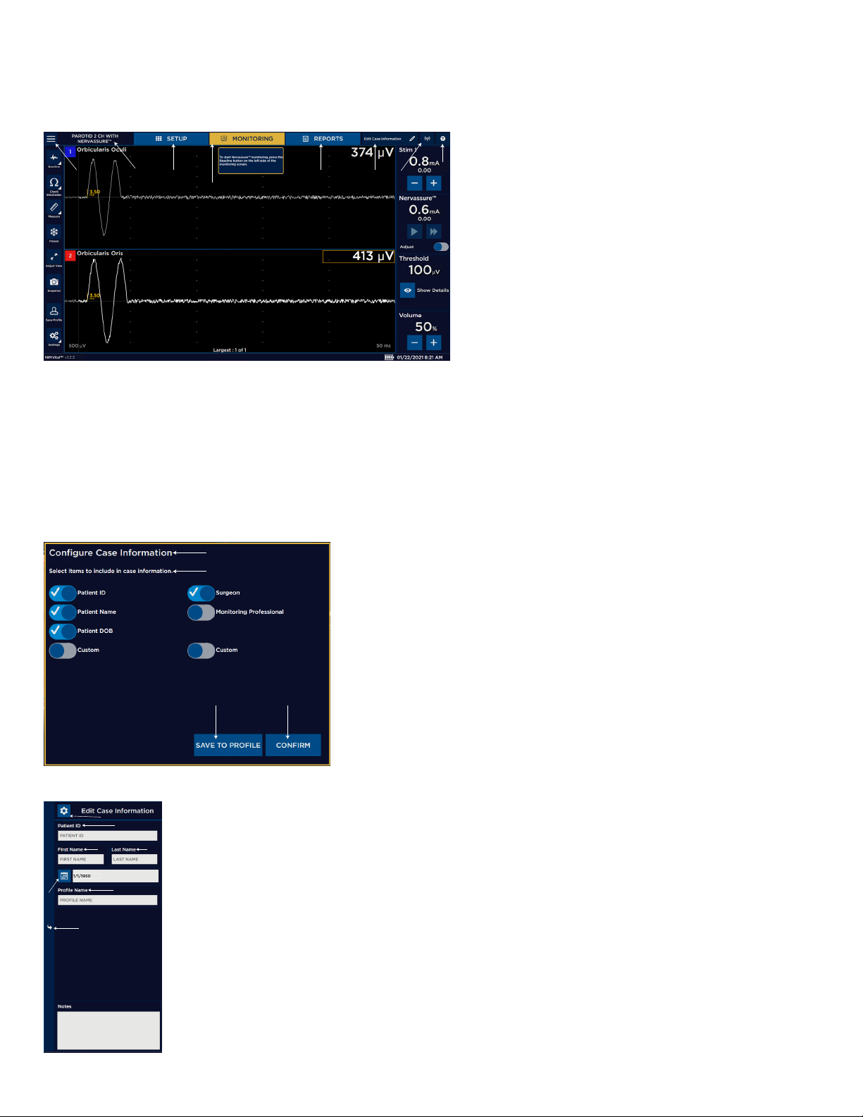
Nerve Integrity Monitor
NIM Vital™ top panel
You can view, add, and update patient information using the Edit case information button located on the top panel of the NIM
Vital™. You can also access the NIM Vital™ Help screen and view the connected devices.
1 Global settings.
2 Current procedure.
1 2
3
4
5 6
7
Edit/congure case information button
The Congure case information setting enables the user to choose which elds appear on the Edit case information panel.
The Edit case information panel opens when you press the Edit Case Information button. Use this screen to enter data into
preselected data elds. The user can modify the Data elds displayed by selecting the icon on the top left of the Edit case
information panel. In the Congure Case Information window, the user can turn on/o each data eld for display in the Edit case
information panel. Select [Save to Prole] to keep the changes in a surgeon prole, or [Conrm] to save the changes for the
current case.
8
3 SETUP tab.
4 MONITORING tab.
5 REPORTS tab.
6 Edit case information button.
7 Type of patient interface connection.
8 Help button.
1
2
1 Congure Case Information setting.
2 Select Items to Include in Case Information.
3 SAVE TO PROFILE.
4 CONFIRM.
3
1
2
3
1 Edit Case Information. Press any of the information elds
to open the keyboard for data entry. Changes are saved
4
automatically.
4
2 Patient ID.
5
6
3 First Name.
4 Last Name.
7
5 Date of Birth.
6 Prole Name.
22
7 Close the Edit Case Information screen.
Page 25
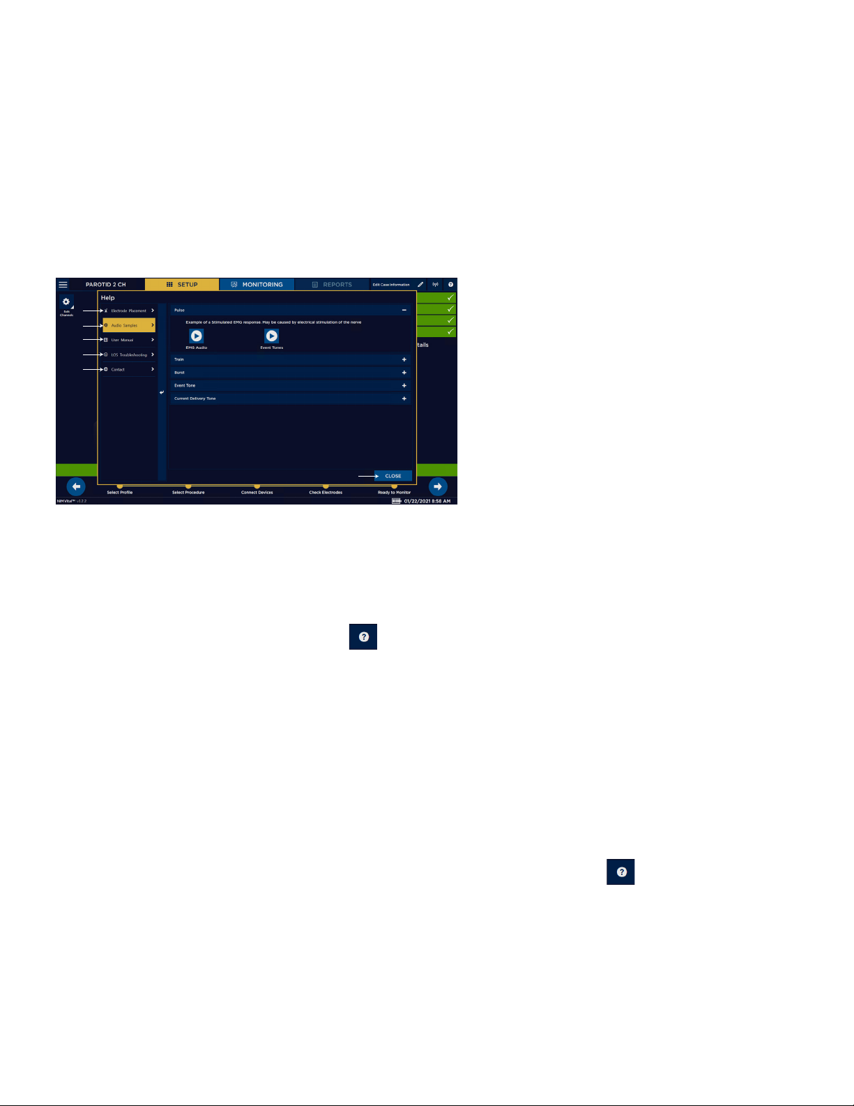
1. From the MONITORING screen, press the Edit Case Information button.
The Case Information screen appears.
2. Press the Surgeon box and type the surgeon information using the on screen or attached keyboard.
3. Repeat step 2 and 3 for the following information depending on conguration:
• Patient ID
• Patient Name
• Patient DOB
• Notes
4. Press the reverse arrow button on the right side panel.
The system returns you to the previous screen.
Help
1 Electrode Placement.
1
2
3
4
5
2 Audio Samples.
3 User Manual.
4 LOS Troubleshooting.
5 Contact.
6 Close Button.
Nerve Integrity Monitor
6
The Help screen displays help graphics for locating electrodes, sample audio sounds, an electronic version of the IFU, LOS
troubleshooting, and contact information.
You can use the Help screen to view electrode placement graphics which aids in the electrode placement and sample audio sounds.
View Electrode placement using the Help screen
You can use the Electrode Placement tab on the Help screen to view electrode placement graphics.
1. In the top right-hand corner of the screen, press .
The Help screen appears.
2. Press [Electrode Placement]
3. Place electrodes according to the appropriate help graphic.
4. Press [Close] to return to the current screen.
Note: When the user accesses the Help screen from the MONITORING screen, the system disables monitoring.
Electrode placement
The surgeon should insert the electrodes into the appropriate muscle location innervated by the monitored nerve. The surgeon
should then insert the ground electrode (green) and the stim return (white) as shown in the electrode placement diagram. Once the
surgeon places the electrodes on the patient, the surgeon needs to insert the other end of the electrodes into the patient interface
to complete the electrode setup. NIM Vital™ systems include nerve and electrode placement guides that are color-coded to help
reduce confusion.
The electrode placement guide contains some, but not all, possible electrode placements. Press on the top right-hand corner
of the screen for an additional list of electrode placement guides.
23
Page 26
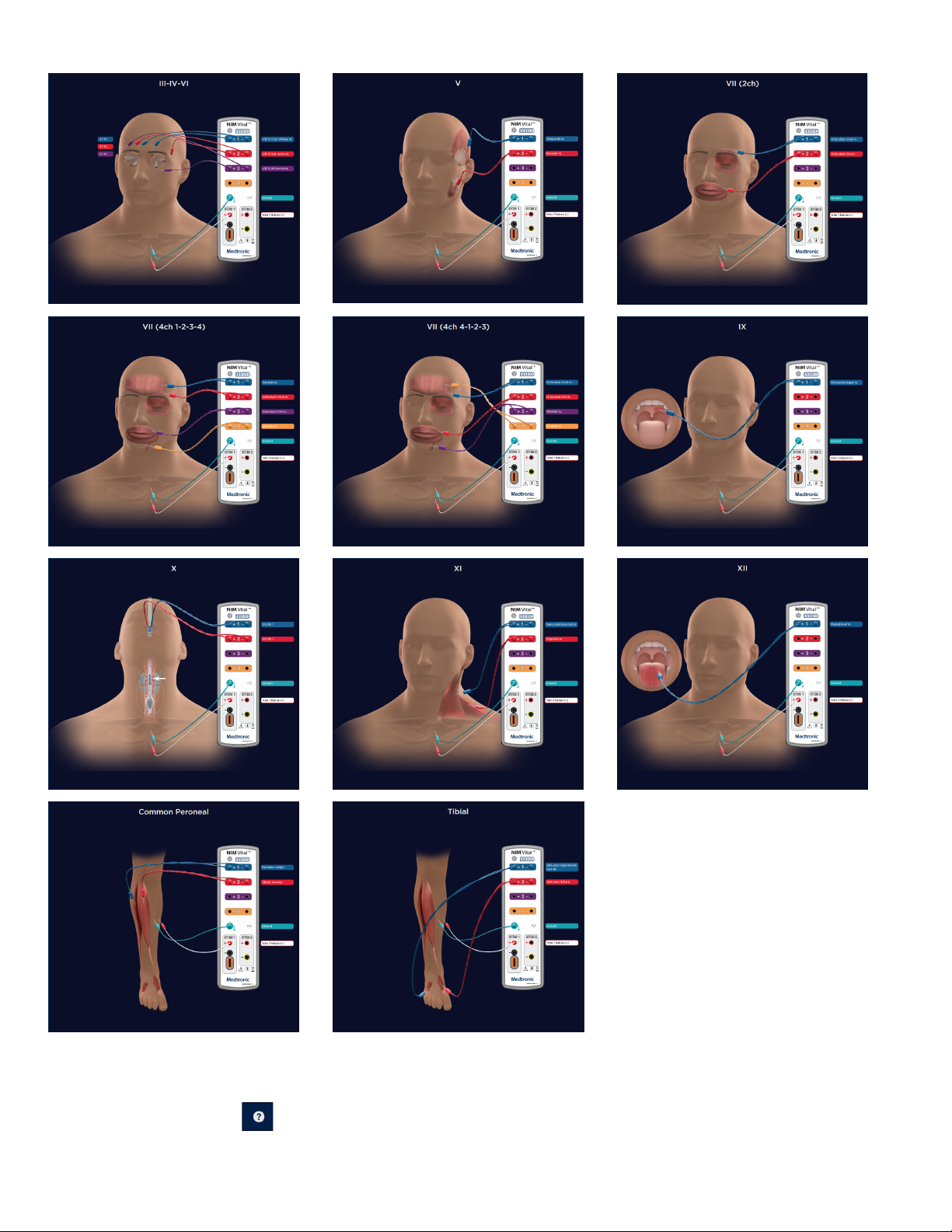
Nerve Integrity Monitor
Listen to audio samples
You can use the Audio Samples tab on the Help screen to hear multiple types of audio.
1. On the SETUP screen, press .
The Help screen appears.
24
Page 27

Nerve Integrity Monitor
2. Select the Audio Samples tab.
3. Select any of the following audio samples:
• Pulse
• Train
• Burst
• Event tone
• Current Delivery tone
4. Press [Close] to return to the SETUP screen.
Note: When the user accesses the Help screen from the MONITORING screen, the system disables monitoring.
View the Instructions for Use
1. On the SETUP screen, press
The Help screen appears.
2. Select [User Manual].
The Instructions for Use appears in the right pane.
3. Use the scroll bar on the right to scroll through the Instructions for Use.
4. Select [DOWNLOAD] (appears when the system detects a mounted, approved USB).
The system downloads the .pdf le the USB drive. Note: The user receives a message stating the system saved the document to
the USB drive after ve seconds. You must wait at least two minutes before removing the USB drive though. It takes the system at
least two minutes to complete the download.
5. Press [Close] to return to the current screen.
Note: When the user accesses the Help screen from the MONITORING screen, the system disables monitoring.
View the LOS troubleshooting information
1. In the top right-hand corner of the screen, press .
The Help screen appears.
2. Press [LOS Troubleshooting].
3. View the intraoperative LOS troubleshooting algorithm.
4. Press [Close] to return to the current screen.
Note: When the user accesses the Help screen from the MONITORING screen, the system disables monitoring.
View contact information
1. In the top right-hand corner of the screen, press .
The Help screen appears.
2. Press [Contact].
3. View Medtronic’s contact information/Remote assistance.
4. Press [Close] to return to the current screen.
Note: When the user accesses the Help screen from the MONITORING screen, the system disables monitoring.
Connected devices
The user views the status of connected devices using . The Connected Devices panel provides detailed information on any
connected patient interface whether it is docked, wirelessly connected, or wired.
Settings overview
Settings/Advanced settings adjustments made in the MONITORING mode lasts for the duration of the session unless the user
presses [Save Prole] which saves the changes in a prole.
25
Page 28
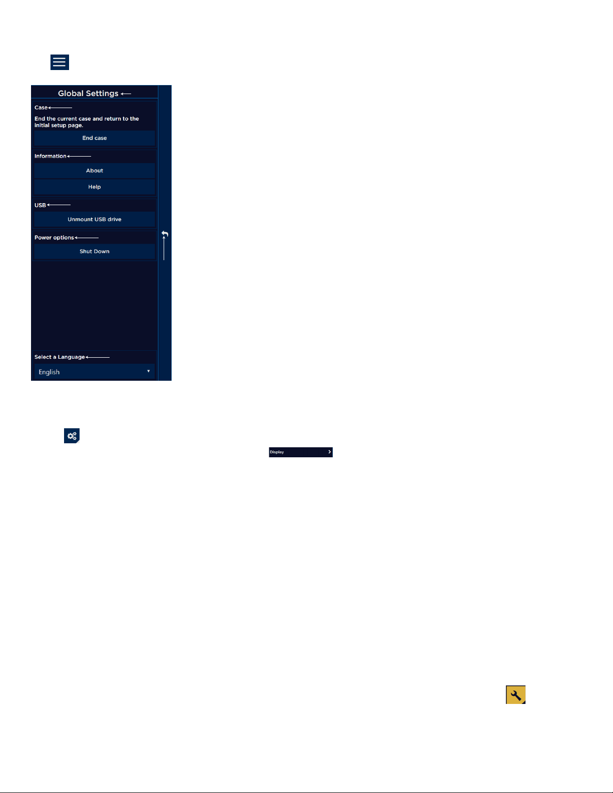
Nerve Integrity Monitor
Global settings
Press to access the Global Settings menu on any screens.
1
2
1 Global Settings screen.
2 Case panel. Press [End case] to end the current case and return to the Select Proles
screen.
3 Information panel. Access the following screens:
• About
3
• Help
4 USB panel (appears when the system detects an approved, mounted USB drive). Press
[Unmount USB drive] to safely remove the USB drive.
4
5 Power options panel. Press [Shut down] to shut down the NIM Vital™ system.
6 Select a Language drop-down menu.
5
6
7 Close the Global settings panel.
7
Accessing settings
The user can only access/modify these settings from the MONITORING tab.
1. Press .
The Settings slider panel buttons appear (for example: ).
2. Select one of the following settings you want to adjust:
• Nervassure™ (available when enabled).
• NerveTrend™ (available when enabled).
• Audio.
• Display.
• Stimulation.
• Titles and Comments
The panel slides out enabling you to make the adjustments.
Note: to open any Advanced Settings panel, the user must accept a dialog box that warns her/him about modifying advanced
settings.
Nervassure™ settings panel
Refer to the “Nervassure™ settings” topic for additional information on Nervassure™ settings.
NerveTrend™ panel
The user must enable the NerveTrend™ panel using the Display panel. Go to Display/Additional Features/Enable NerveTrend™ toggle
button. Once the user selects Enable NerveTrend ™“on”, the system shows the NerveTrend™ panel and the user can now access the
NerveTrend™ settings/advanced settings.
Note: If you adjust the advanced settings, you will change the default characteristics of your NIM Vital™. Only someone with
knowledge of the advanced settings and how they impact your NIM Vital™ should make changes. If the user selects , the system
displays a warning. The user must select [Cancel] or [Conrm] to return to settings or move forward to the advanced settings panel.
26
Page 29
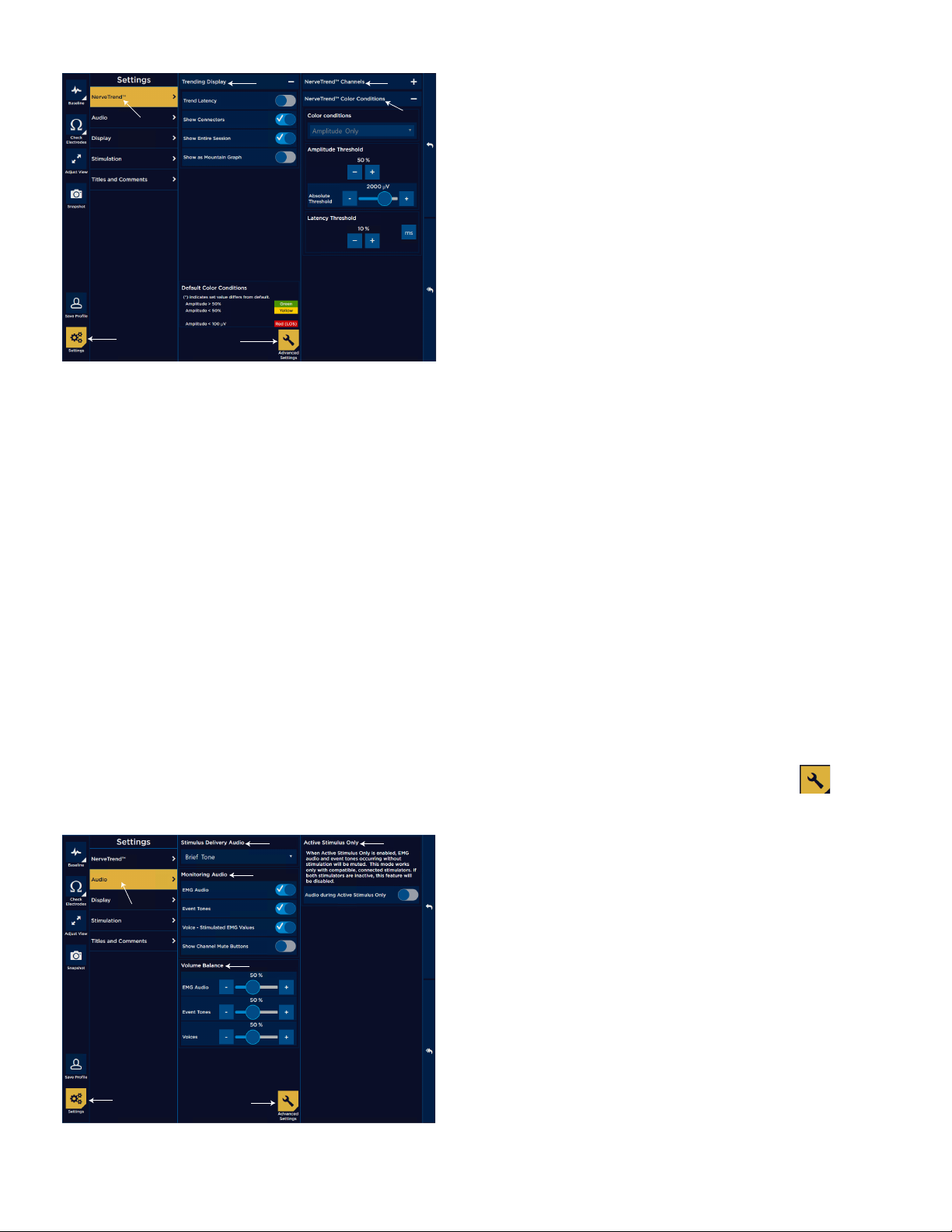
Nerve Integrity Monitor
3
5
3
7
1 Settings button.
2 NerveTrend™ settings.
2
6
3 Trending Display expand/collapse menu:
• Trend Latency.
• Show connectors.
• Show Entire Session.
• Show as Mountain Graph.
4 NerveTrend™ settings advanced settings.
5 NerveTrend™ Channels.
6 NerveTrend™ Color Conditions expand/collapse menu:
• Color Display Criteria.
• Amplitude Threshold.
1
4
• Absolute Threshold.
• Latency Threshold.
On the NerveTrend™ settings panel you can select the following diverse types of trends to track:
• Trending Display settings - you can toggle on/o the following settings from the Trending Display settings panel:
— Trend latency - Turn on latency for the trending area.
— Show Connectors - Display connecting lines between trend points.
— Show Entire Session – When enabled, the system displays the entire session in the trend window. When disabled, the trend is
on a rolling timeframe that only shows the most recent portion of the trend session.
— Show as Mountain Graph - Change the visual layout of the trend.
• Color Conditions - View the alarm color conditions. The Color conditions depend on the Alert Type setting (amplitude/latency).
The user must enable Trend Latency to use a latency Alert Type.
NerveTrend™ advanced settings
On the NerveTrend™ advanced settings panel you can adjust the following:
• NerveTrend™ Channels - Toggle on/o the EMG channels in the procedure to trend.
• NerveTrend™ Color Conditions - You can adjust the following color condition information:
— Condition Type (amplitude only, latency only, amplitude AND latency, Amplitude OR latency)
— Amplitude Threshold
— Latency Threshold
Audio panel
Refer to the “Audio – understanding what you hear” topic for more information on the Audio tab.
Note: If you adjust the advanced settings, you will change the default characteristics of your NIM Vital™. Only someone with
knowledge of the advanced settings and how they impact your NIM Vital™ should make changes. If the user selects , the system
displays a warning. The user must select [Cancel] or [Conrm] to return to settings or move forward to the advanced settings panel.
1 Settings button.
4
2 Audio panel.
3 Stimulus Delivery Audio.
2
4 Monitoring EMG Audio:
• EMG Audio.
5
• Event Tones.
• Voice - Stimulated EMG Values.
• Show Channel Mute Button.
5 Volume Balance:
• EMG Audio Volume Balance.
• Event Tones Volume Balance.
• Voices Volume Balance.
1
6
6 Audio Advanced Settings.
7 Active Stimulus Only.
27
Page 30

Nerve Integrity Monitor
Additional options for the Stimulus Delivery Audio panel (3):
• Brief Tone (default). Delivery of stimulus current is accompanied by a brief warbled tone.
• Continuous Tone. Delivery of stimulus current is accompanied by a continuous, warbled, high-low tone (referred to as “Stimulus
Warble Tone”).
• Voice - Stimulus. Delivery of current to the surgical eld is announced by the word, “STIMULUS”.
• Voice - Setting. Delivery of current to the surgical eld is announced by the value of the stimulus setting.
Note: You will not hear the Stimulus Delivery Audio when an event has occurred.
The following options are located on the Monitoring Audio panel. At least one selection must be active, however you may select all
three options.
• EMG audio is the amplied sound of muscle activity that is heard instantaneously as the nerve is stimulated. All EMG activity,
regardless of amplitude, is audible when the EMG audio is ON. The EMG activity may sound like a low-pitched “drumbeat”, a highpitched “crackle,” or a “growl”. When you monitor multiple channels, it is unlikely that you will be able to dierentiate the EMG
signals as to their channel of origin strictly by the sounds they produce.
• Event Tones are heard when the EMG amplitude is larger than the Event Threshold setting. The Event Tones are easily heard over
O. R. noise and are heard at the same time with the EMG audio, previously mentioned.
• “Voice – Stimulated EMG Values” announces the value of the highest channel in the largest event in a sequence if largest
is selected in Display settings (approximately one second after the sequence ends). The system rounds the actual value
appropriately for annunciation. For example, the NIM Vital™ system would announce 623 as “six hundred twenty.”
You can dierentiate channels by tone pitch. The tone for channel 1 activity is lower in pitch than channel 2, and so on for channels
3 through 4. When EMG activity exceeding the event threshold occurs at the same time on multiple channels, only the tone of the
channel with the highest EMG activity will be produced.
You can mute individual EMG channels by selecting Show Channel Mute Buttons.
Once the user enables a monitoring audio option (EMG Audio, Event Tones, or Voice - Stimulated EMG Values), the system displays a
volume balance for the option. All of the balances in this panel default to 50%.
Audio advanced settings
On the Audio advanced settings panel the user can toggle on/o Audio during Active Stimulus Only. When the user enables the
Active Stimulus Only, the system mutes the EMG audio and event tones occurring without stimulation. This mode only works with
compatible, connected stimulators.
Display Settings panel
Note: If you adjust the advanced settings, you will change the default characteristics of your NIM Vital™. Only someone with
knowledge of the advanced settings and how they impact your NIM Vital™ should make changes. If the user selects , the system
displays a warning. The user must select [Cancel] or [Conrm] to return to settings or move forward to the advanced settings panel.
28
Page 31

Nerve Integrity Monitor
2
3
4
5
1
6
10
11
12
1 Display settings.
2 Display Transient Events.
3 Auto Threshold.
4 Single Channel Mode (in Thyroid procedures only).
5 Sequence Display.
6 Latency.
7
13
14
15
7 Additional Features:
• Enable Quick Tags.
• Show Measure Button.
• Show Freeze Button.
8
9
• Enable NerveTrend™.
8 Snapshot Default Actions:
• Comment.
• Print.
• Save To File (only enabled if the system detects a mounted,
approved USB drive).
9 Display Advanced Settings.
10 Waveform Filters:
• Artifact Filter.
• Low-Pass Filter.
• High-Pass Filter.
11 ESU Filter.
12 ESU Muting Level.
13 Reject Stim Pulse Artifacts.
14 Rejection Period.
15 Research Settings:
• Display Raw EMG as Transients.
• Record Waveform Data.
When you activate the Measure button (by enabling it in the display settings), the on screen cursor (green) shows the amplitude (V)
and time (mS) at the cursor location.
• Time is measured from zero (0) not from Stimulus/Rejection Period.
• Amplitude is measured from the channels zero (0) with a minus (-) sign for negative numbers.
If the users selects Display Transient Events, the system enables transient events. With Event Capture disabled, free running EMG
signals scroll across the screen at real-time. When an Event occurs, the signal persists as a transient event on the screen for ve
seconds before fading away.
If you selected Auto Threshold on the Events panel and the event tones are continuous for 10 seconds:
• Auto Threshold automatically calculates a new Event Threshold (to a maximum of 400V).
• You will hear all activity less than the new Event Threshold as raw EMG.
• EMG activity greater than the new Event Threshold or greater than 400V generates Event Tones.
• The Event Threshold returns to the original value after 10 – 20 seconds of no, or decreased, event activity.
• Single channel mode is only available in Thyroid procedures and is enabled by default. When single channel mode is on,
the system presents the channel with the best amplitude. For more on how single channel mode aects trending, see the
“Nervassure™” topic.
• In the Sequence Display panel, the system selects the Largest Overall option by default. The following happens:
— If Last and Event Capture are selected, the most recent event appears until replaced with a new or more recent event.
— If Largest Overall and Event Capture are selected, and multiple events occur over a period of time, then the largest event from
the series (the series end when the stim probe is removed) of events appear as Largest x of x (example 3 of 5).
— This remains on screen until replaced with the next event or next largest event from a series of events.
On the Latency panel, you can do the following:
• Control whether the system shows latency values in stimulated waveform sweeps using the Latency selection button.
29
Page 32

Nerve Integrity Monitor
• Control whether the system measures latency to the onset of the response, or to the highest peak EMG value of the response by
selecting Onset or Peak from the drop-down menu.
• If the user has Latency enabled on the Latency panel, then for every stimulation pulse that causes a response greater than 20 µV,
the system displays the Latency value on the waveform. It may be measured to the onset of the response or to the highest peak
EMG value of the response depending on the settings you chose.
On the Additional Features panel, the user can do the following:
• Enable Quick Tags. This displays quick tags on the Quick Tags panel on the right hand side of the monitoring screen. See the
“Quick Tags” topic for more information.
• Show Measure Button. This displays the measure button in the left panel enabling the user to use the measure feature. See the
“Measure” topic for more information.
• Show Freeze Button. This displays the freeze button in the left panel enabling the user to freeze the waveform display. See the
“Freeze” topic for more information.
• Enable NerveTrend™. This turns on NerveTrend™ functionality by presenting NerveTrend™ settings in the settings panel and
enabling NerveTrend™ baseline to be taken.
On the Snapshot Default Actions panel, you can do the following:
• Choose the default snapshot actions using the Comment, Print, and/or Save To File selection buttons. You can select more than
one action.
• Select the Probe Saves Snapshot to control whether the center position on the incrementing stimulus probe saves a snapshot.
• If the center button is enabled and the Comment button is selected, then when you press the center probe button:
— The title/comment box pops out.
— One of the titles in the list is selected.
— The up/down buttons on the probe now do not change the stim current, but rather move the highlight bar up and down the
title list.
• Comments. Opens comments box enabling comments and Event Titles (you may enter titles via keyboard or select them from a
customized list) to be added to the captured event when you press the Snapshot button. The system displays these comments/
title on the printed and/or saved event. Refer to the “Titles and Comments Panel” topic to customize this list.
Note: You can modify Comments and Event Titles in Reports Mode.
• Print. Sends captured event to the printer (with comments enabled) when you press the Snapshot button.
• Save. Sends captured event to the USB mass storage device (with comments if enabled it) when you press the Snapshot button.
You can use the Waveform Filters panel to toggle the artifact lter on/o. If you select the artifact lter you can control the following
waveform lters:
• Artifact Filter: selecting the artifact lter enables the detection of artifact as “Spiked Waveforms” .
• Low-Pass Filter: low frequency response is generally caused by the movement of the electrodes, electrode wires, tissue etc.
This can result in a response that is not a true EMG response. Selecting the low-pass lter enables a lter that reduces peak-topeak amplitude (about 20%) in a frequency range below 70Hz reducing unwanted response. The lter is on by default for all
procedures.
• High-Pass Filter: reduces frequencies seen above the set value.
• Reject Stim Pulse Artifacts: enables the artifacts rejection lter. Refer to the “Recognizing stimulus artifacts” topic for additional
information.
• Rejection Period: the user can set the STIM rejection period time.
• The ESU Filter automatically suppresses interference from monopolar electrosurgical equipment.
• The ESU Muting Level control adjusts the sensitivity of the ESU Filter.
— Increase the ESU Muting Level when the ESU Filter is not adequately suppressing monopolar electrosurgical interference.
— Decrease the ESU Muting Level if the system excessively mutes when used on a patient and activates the ESU Filter even
though no electrosurgical equipment is in active use.
Stimulation panel
Use the Stimulation settings panel to make adjustments to stimulators, such as assigning names and probe types.
Note: If you adjust the advanced settings, you will change the default characteristics of your NIM Vital™. Only someone with
knowledge of the advanced settings and how they impact your NIM Vital™ should make changes. If the user selects , the system
displays a warning. The user must select [Cancel] or [Conrm] to return to settings or move forward to the advanced settings panel.
30
Page 33

1 Stimulation panel button.
2
3
4
1
5
7
8
9
2 Stimulator 1 Name.
3 Stimulator 1 Probe Type.
4 Stimulator 1 Rate and Pulse Width.
5 Stimulator 2. Note: The identical settings for STIM 1 appear for
10
6 Advanced Settings button.
7 Stimulator 1 Pulse Type.
8 Stimulator 1 Train Count.
9 Stimulator 1 Current Warning Level.
10 Stimulator 2. Note: The identical settings for STIM 1 appear for
6
Identify STIM 1 and STIM 2 types
1. Press .
The Settings panel appears.
2. Press the Stimulation button.
The Stimulation panel appears.
3. Do one of the following:
• Select STIM 1.
• Select STIM 2.
4. Under the Name eld, press the STIM Name drop down arrow.
A list of pre-dened STIM types appears.
5. Select a STIM type from the list.
Nerve Integrity Monitor
STIM 2 if it is connected and Stim mode is set to normal.
STIM 2 if it is connected and Stim mode is set to normal.
6. Click to close the panel.
The system saves the probe name.
The following is an example of a pulse width and rate adjustment performed on the Pulse Width and Rate panels.
Pulse width and Rate diagram (number of pulses per second)
Note: If you selected a Nervassure™ procedure, then the Stimulator 2 Rate adjustment will be located on the Nervassure™ Tab.
In the Stimulation advanced settings, the user can change the pulse type which alters the polarity of pulses generated by the
stimulator. Selecting any of the biphasic options enables an Interphase Delay option to appear. Interphase Delay changes the time
between pulses of dierent polarities during a single period. The user can also adjust the train count – number of repetitions of a
pulse for each polarity that occur within a single period. Selecting any train count (the number of pulses in a series of pulses) higher
than one enables an Interpulse Interval. The Interpulse Interval changes the time between pulses that occur in the same polarity.
The following is an example of these adjustments.
Important note on stimulator adjustments
By selecting a procedure, the default settings for stimulus intensity normally provide adequate stimulation. The absolute stimulus
intensity required to adequately stimulate any motor nerve is determined by a complex combination of several factors including
31
Page 34

Nerve Integrity Monitor
(but not limited to) the following:
• The functional health of the nerve itself.
• The type of stimulation probe used (monopolar or bipolar).
• Proximity to the nerve.
• The pulse width of the stimulus.
You should use the amount of stimulation necessary to elicit a detectable EMG event. Stimulus current levels of 0.3mA may be high
enough for adequate direct monopolar stimulation of the facial nerves, but may elicit little or no response when monitoring nerves
during thyroid procedures. The best guideline for setting the stimulus intensity level is to use the lowest amount that produces an
EMG event. Under- and over-stimulation are covered under W19, W20, and W26 in the “Warnings” topic.
The surgeon should be aware:
• That STIMULUS is continuously being applied to the STIMULATOR probe and/or the Nervassure™ stimulator.
• STIMULATING the patient is the result of physical contact between the patient and the STIMULATOR probe.
• The STIMULATOR probe should be kept ISOLATED when NOT STIMULATING the patient (except Nervassure™).
Note: Stimulator adjustment involves the adjustment of the Current, Rate, Pulse Width, and the Stimulus/Rejection Period.
Note: To prevent inadvertent high stimulus levels, the rst time the stimulus level exceeds the Current Warning Level (9), a dialog
box opens:
• Stimulus in excess of the current warning level (usually 3 mA).
• Press [CONFIRM] to enable stimulus.
If using the procedures Lower Extremity, Knee, or Ankle, the stimulus level warning is set at 12.0 mA.
32
Page 35

Nerve Integrity Monitor
NIM Nerve Stimulator probe types and best usage range
The NIM Vital™ has an increased maximum stimulation current from the 30mA used in the prior generation NIM 3.0™. The NIM
Vital™ has a more capable 50mA stimulation current to facilitate stimulating a nerve from a distance, or to compensate for current
shunting. The utility of more capable stimulation levels includes the following:
• Stimulating with electrodes types with larger surface areas and electrodes that stimulate through larger volumes of overlying
tissue.
• The need for stimulation parameter increases to compensate for monitoring and locating in cases which include:
— Clinical neuro-weakness.
— Neuro-anatomical-variation.
— Stimulation of the nerve in a weakly-innervated muscle.
• Stimulation for pre-operative incision planning that requires higher stimulation/compliance levels for transcutaneous nerve
mapping using a large surface area ball-tip probe to stimulate the underlying nerve tissue.
• Stimulation of nerves using larger surface-area skin electrodes necessary for patients who are:
— Obese.
— Diabetic.
— Diagnosed with a neuropathy condition requiring higher stimulation levels to evoke nerves due to the physiological
condition or distance of these nerves from the stimulation site.
The NIM monitors have pre-programmed setups for most common procedures and are almost exclusively used at these well
designed default settings with an occasional adjustment of a few mA of stim current. The NIM Vital™ has the same defaults as the
previous NIM 3.0™ monitor for:
• Stimulation current initial settings.
• Stimulation waveform parameters.
• Stim current message adjustment alert levels to facilitate continued normal routine use.
There are two main types of stimulator probes for intermittent monitoring:
• Monopolar with a single stimulating contact like the Prass Probe, or instrument for stimulation/locating the nerve.
• Bipolar probes with two stimulation contacts like the Concentric Bipolar Probe used for stimulation/dierentiating a nerve.
Intracranially, smaller stimulator probes are used at lower currents. Extracranial stimulation is used at normal currents or larger
currents in special monitoring situations.
The NIM Vital complies with IEC 60601-2-40 Medical Standard Particular requirements for the basic safety and essential performance
of electromyographs and evoked response equipment. All of the NIM Vitals’ default procedure settings are less than 2mA/cm2
root mean square (RMS) current density. The NIMs are used safely at the default procedure settings.
Special consideration is needed if exceeding NIM default settings or conditions. Levels higher than 2 mA /cm2 RMS may result in
tissue damage (refer to warning W26). The primary risk of over-stimulation during intermittent monitoring is the potential injury of
unintended patient movement (refer to warning W20). Also, refer to the NIM Stimulator Probe Current Density (Rev. 201027) table.
NIM probe type typical uses
• Standard Prass probes are used in most neuromonitoring applications.
• Slim Prass probes, Prass Bipolar probes, and Yingling probes are the smallest NIM probes and are more sensitive to excessive
current densities. They are best used Intracranially, at or near default currents, or less than 2mA /cm RMS.
• Ball tip probes and surface electrodes can be used at higher default setting current amplitudes because the larger surface
area distributes the current density. Use caution if exceeding a current density of 2mA /cm2 RMS. Ball Tip probes are used for
mapping from larger distances or stimulation of nerve through skin or instrumentation.
• NIM Stimulating instruments can be used at default and higher current amplitude stimulation settings. Use caution if exceeding
a current density of 2mA/cm2 RMS.
33
Page 36

Nerve Integrity Monitor
NIM Stimulator Probe Current Density
Note: All NIMs default procedure settings are
less than 2mA/cm2 (RMS) current density.
Description of Stim Contact area (mm2)
The lowest NIM Vital™ Current setting (mA) that should not exceed 2mA/
cm2 RMS Current density.
NIM Vital™ or NIM 3.0™
default stimulation
settings (100 μsec, 4
pps)
NIM Vital™ Modied
Max Stim settings
(250 μsec, 20 pps, TOF,
Biphasic)
NIM Vital™ Advanced
Max stim settings
(1000 μsec, 20 pps,
Biphasic)
The currents below are not the NIM default currents
Probes
Prass Standard 0.204 10.2 mA 0.8 mA 0.2 mA
Prass Slim
1 mm Ball Tip 1.26 63.0 2.5 0.6
2.3 mm Ball Tip 6.65 332 13.3 1.3
Yingling Probe 0.65 32.5* ‡ ‡
Prass Bipolar Probe 0.0415 2.1* ‡ ‡
Concentric Bipolar Probe 0.5343 26.7 1.1 0.3
Side-by-Side Bipolar Probe 0.644 80.6 3.2 0.8
Electrodes
Subdermal Needle 12.56 628 25.12 6.3
Subdermal Needle twisted
Pr.
Prass Paired 82-27410 5.02 251 10 2.5
Surface Electrode 82-
27767
Stimulus Dissection Instrument Probes, SDI Probes
Curved Needle .99 27 5.4 0.3
Curved Elevator 6.5 340 13.6 3.4
Ring Dissector 2.0mm 2.0 54 10.8 0.6
Stimulus Dissection
Forceps
Neurotologic Dissection Instrument Probes, NSD Probes
Right Angled Pick, Long 0.68 34.0 1.4 0.3
Curved Needle 3.27 163 6.5 1.6
Duck Bill Elevator, Medium 2.21 110 4.4 1.1
Duck bill Elevator, Wide 2.87 143 5.7 1.4
Raspatory, Narrow Right 0.85 42.5 1.7 0.4
Shaded cells indicate the current density could exceed 2 mA/cm2 at a current setting less than the maximum Stimulation setting.
*Slim Prass Probes, Prass Bipolar Probes, and Yingling probes are the smallest NIM probes which are used at default settings or currents less than 2.0mA. It is
recommended that these probes are used intracranially in small spaces.
‡ Not recommend, use exceeds which 2mA/cm2 RMS Current density.
0.086 4.3* ‡ ‡
0.166
1.1165
0.644
22.11 1105 44.2 11.1
455 22750 3640 227
4.0 27 21.6 1.2
NIM Probe Current Density Rev. 201027
34
Page 37

Titles and comments
Nerve Integrity Monitor
1 Enable quick tags toggle.
1
2
2 Edit custom titles and comments list.
3 Move forward/backward through title/comment list.
4 Selected item is a quick tag title toggle.
5 Create a new title/comment/quick tag.
6 Edit a title/comment/quick tag.
7 Delete a title/comment/quick tag.
3
6 7
4
5
The edit custom titles and comments feature enables you to create new titles/comments or delete entries that have already been
created including the default titles. The Edit and Delete buttons appear when you select an existing item in the list. The titles/
comments specic to the procedure type that the user is monitoring.
1. Press .
The Settings panel appears.
2. Press the Titles and Comments button.
A list of titles for the current procedure appears.
3. Do any of the following:
• Select [New] to create a custom title/comment. Use the on-screen or attached keyboard to type a title or comment.
• Select a title, press [Edit] and then edit the existing title.
• Select a title, press selected item is a Quick Tag title toggle. See the “Quick Tags” topic for more information.
• Select a title, press [Delete]. The system deletes the title. This option is not available if the title is a quick tag that has already
been used during the procedure.
4. Press to close the settings panel.
Optional features in monitoring
Quick tags
You can use the Enable Quick Tags toggle slider to display the abbreviation of the title that appears on a quick tag button on the tool
bar at the right of the screen during the Monitoring phase. You can activate a quick tag by selecting a title and then select “Selected
item is a Quick Tag title” toggle. Type an abbreviation for the title of the button using the pop-up that appears.
1. Select the Enable Quick Tags toggle slider.
2. Select the Selected item is a Quick Tag title toggle slider.
The Edit Title/Comment Abbreviation pop up appears with the title/comment name in the Title/Comment box.
3. Press the Abbreviation box.
The Abbreviation pop up appears with the choice to use an on screen keyboard, or use your attached keyboard.
4. Type the abbreviation you want to use for your quick tag and press [CONFIRM].
Note: the system adds new titles to the end of the quick tag list.
35
Page 38

Nerve Integrity Monitor
Probe-based functions
The (single use) Incrementing Probe provides the surgeon with the means to adjust the stimulation current at surgical site.
2 3
1
1 - Toggle button normal or at rest.
2 - Increase (plus).
3 - Decrease (minus).
4 - The user can perform the following functions with the toggle button:
• Momentary press saves a snapshot of the current screen to memory (for reports) and to a selected peripheral device (printer
and/or USB ash drive) if the user selected that option in the settings area.
• Press and hold opens a menu on the user interface with more options.
Control stimulation and volume using the probe
By default, the increase (plus)/decrease (minus) positions control stimulation values and annunciate the newly set stimulation
current. There are two methods the user can use to toggle between stimulation and volume controls.
Method 1
1. Press the increase (plus) position for two seconds.
The probe’s increase (plus)/decrease (minus) positions now control volume and provides audio feedback of the volume level.
2. When in the volume mode, press the increase (plus) position for an additional two seconds.
The probe’s increase (plus)/decrease (minus) positions now control stimulation. If the probe is in volume mode, after 30 seconds
of no use it defaults back to stimulation control.
Method 2
1. Press the toggle button for two seconds.
A menu appears.
2. Use the increase (plus)/decrease (minus) positions to navigate through the menu options and select [Volume].
The probe’s increase (plus)/decrease (minus) positions now control volume and provide audio feedback of the volume level.
3. Press the toggle button for two seconds.
A menu appears.
4. Use the increase (plus)/decrease (minus) positions to navigate through the menu options and select [Stimulus].
The probe’s increase (plus)/decrease (minus) positions now control stimulation. If the probe is in volume mode, after 30 seconds
of no use it defaults back to stimulation control.
Note: When the user toggles between the stimulation and volume controls an audio cue is heard.
Create a snapshot using the probe
If the user quickly presses the toggle button during monitoring, the system takes a snapshot.
Set a NerveTrend™ baseline using the probe
If NerveTrend™ is enabled, the user can use the probe to initiate a NerveTrend™ baseline. Refer to the “NerveTrend™” and “Creating a
NerveTrend™ baseline” topics for additional information. You must have NerveTrend™ enabled to use the following procedure.
1. Press the toggle button and select Baseline from the menu.
The system begins the NerveTrend™ baseline process.
2. Use the plus/minus positions to move through the bottom control buttons and select [Continue].
The second baseline screen appears showing the operative side selection panel.
3. Use the plus/minus positions to select the right/left operative side, then press the select button.
Once the user has selected the operative side using the probe, the system focuses on the bottom control buttons.
4. Use the plus/minus positions to move through the bottom control buttons and select [Accept].
4
36
Page 39

Nerve Integrity Monitor
Set a NerveTrend™ trend point
1. Press the toggle button once there is a point ready to trend. Refer to the “Using the NerveTrend™ feature” topic for additional
information.
A menu appears.
2. Use the increase (plus)/decrease (minus) positions to select whether to apply the trend point to the graph (which also takes a
snapshot) or only take a snapshot.
3. Press the toggle button to apply your selection.
Select a quick tag using the probe
The user can access quick tags, if they have been enabled (refer to the “Titles and Comments” topic for additional information), using
the following procedure.
1. Press the toggle button for two seconds.
A menu appears.
2. Use the increase (plus)/decrease (minus) positions to navigate through the menu options and select [Quick Tags].
The system expands the quick tag area.
3. Use the increase (plus)/decrease (minus) positions to navigate through the existing quick tag list.
4. Press the toggle button once you have highlighted the specic quick tag you want to use.
The system applies quick tag and closes quick tag area.
Note: If no action is taken for 10 seconds, the quick tag area shrinks.
Nervassure™ functions using the probe
The following Nervassure™ functions are available using the incrementing probe.
Set a Nervassure™ baseline using the probe
1. Press the toggle button for two seconds while in a Nervassure™ procedure.
A dialog box appears.
2. Use the increase (plus)/decrease (minus) positions to move through the menu options and select [Baseline].
The system begins the baseline process.
3. Use the increase (plus)/decrease (minus) positions to move through the bottom control buttons and select [Continue].
The second baseline screen appears showing the operative side selection panels.
4. Use the plus/minus positions to select the right/left operative side, then press the select button.
Once the user has selected the operative side using the probe, the system focuses on the bottom control buttons.
5. Use the increase (plus)/decrease (minus) positions to move through the bottom control buttons and select [Accept].
REPORTS tab
Note: All stored case data (snapshots, log les, Nervassure™ data, and reports) is lost when unit is powered o.
The REPORTS mode enables you to quickly compose and print/save reports using a report builder. The system provides report
templates to simplify report creation.
The REPORTS mode can be active while audio monitoring continues in the background. The system saves all work performed in
REPORTS mode if you exit REPORTS and return to MONITORING. For example, you can start a report midway through a monitoring
session. When you return to MONITORING to complete the session, all previous work is available when you return to the REPORTS
mode. When you turn the system o, you lose all monitoring session data.
37
Page 40

Nerve Integrity Monitor
1 Live Preview window: Displays auto-generated report.
Use the tabs to jump to bookmarks within the report.
3
2
1
4
2 Live Preview expand: Expands the report to a two-
page at a time view.
3 Modify Report Panel: Options to edit Quick Tags,
Snapshots, and baseline sessions in the case.
4 Export Report Panel: Options to save a .pdf version of
the report to a USB (if the system detects a mounted,
5
approved USB) and to print the report with a
connected printer.
5 Save To File button: Saves a copy of the case to a USB
(if the system detects a mounted, approved USB).
Include quick tags on a report
By default, the system includes all quick tags the user creates during monitoring on the report. Once the user makes all quick tag
changes to the snapshots (the user can change multiple quick tags at once), the user can create a report.
1. Select [Edit Quick Tags].
The Modify Quick Tags screen appears.
2. Select a quick tag from the left side panel.
3. Select a snapshot from the center of the screen.
4. Press [Include in Report].
The system adds the quick tag to the report.
5. Do one of the following:
• Select [CONFIRM] to save your changes.
• Select [RESET] to revert snapshots back to their last saved state prior to the editing session.
Delete quick tags from the report
1. Select [Edit Quick Tags].
The Modify Quick Tags screen appears.
2. Select a quick tag from the left side panel.
3. Press [Include in Report] twice to toggle it o.
The system removes the quick tag from the report.
Edit the snapshot title and comments
1. Press [...] on the snapshot.
The system opens an editing dialog box.
2. Do one or both of the following:
• Edit the title.
• Add comments
Note: The system displays a larger image of the captured waveforms when the user selects [...].
Include snapshots on a report
By default, snapshots taken during monitoring are not automatically placed in the report.
1. To select a snapshot for inclusion, press the snapshot and the system highlights it.
2. Do one of the following:
• Press [Select All] to highlight all of the available snapshots to add to the report.
• Press [Clear All] to deselect all of the snapshots on the report.
3. Do one of the following:
• Select [CONFIRM] to save your changes.
• Select [RESET] to revert snapshots back to their last saved state prior to the editing session.
Note: In a NerveTrend™ procedure, the user can lter snapshots automatically taken when the user plots a trend point.
38
Page 41

Nerve Integrity Monitor
Edit sessions
By default, the session includes all sessions started during monitoring on the report.
1. Press [...] on the session.
The system open a dialog box for editing the session title and comments as well as displays the session start and stop times with
a composite view of the session trend.
2. Do one of the following:
• Select a single session (the system highlights the selected session).
• Select [Select All] to select all sessions.
• Select [Clear All] to deselect all session.
3. Do one of the following:
• Select [CONFIRM] to save your changes.
• Select [RESET] to revert session back to their last saved state prior to the editing session.
Include trending graphs in a report - Nervassure™ and NerveTrend™
After completing either a Nervassure™ or NerveTrend™ case with a trend graph, the Reports screen automatically includes all trends
in the report. The user can modify the trends shown in the report.
1. From the Modify Report area on the Report Screen, do one of the following:
• Press [Nervassure™], or
• Press [NerveTrend™]
2. Press [Edit] to edit the Title or Comment for the trend, then select the trend to modify.
The system opens a dialog box for modications.
3. Press [Conrm] to save changes.
The system includes all trends that have a yellow border in the report.
Remove a trend
1. Click the trend thumbnail to remove the border.
2. Click [Conrm].
The system regenerates the report.
Add a trend
1. Click the trend thumbnail so the yellow border shows.
2. Click [Conrm].
The system regenerates the report.
Edit case information on a report
The system automatically includes Case information on the report. To edit case information prior to saving/printing, use the Edit
Case Information tab on the top right of the screen to make any required adjustments.
After completing a case, the user can edit case information on the Reports screen.
1. Press [Case Information] from the Modify Report area.
The system opens a panel on the right side of the screen.
2. Edit the information for the currently displayed case.
3. Press [Apply Changes].
The system regenerates the report with the updated case information.
Generate the report
Once the user is satised with the report content, the user can make a nal review of the report using the live preview window. The
tabs at the top of the window enable the user to jump to bookmarks for each section within the report, or use the expand button to
move through the report in its entirety. The user can select from the following options:
• Print button - sends the report to the attached printer.
• Save button - sends the report to the attached USB mass storage device and saves the formatted report as a .pdf format
on the USB drive. The system formats the lenames with the report type, year, month, day and time. For example,
Report_20190528_112530.pdf.
Reports are located in a case folder titled with date, sequential case, and procedure type.
39
Page 42

Nerve Integrity Monitor
Nervassure™ overview
The following topics contain information about how a Nervassure™ procedure is conducted.
Automatic periodic stimulation (Nervassure™) is a process wherein a nerve at risk is continuously stimulated. The resulting EMG is
monitored and charted continuously in real time.
The plotted characteristics are:
• EMG amplitude (peak-to-peak, response to stimulation).
• Latency (time from stimulation to the “Onset” or peak of the EMG response), if enabled.
Every point plotted in the bottom half of the trend chart for each channel is a single EMG amplitude response. Each point plotted in
the top half of the trend chart for each channel is a latency response.
If a measurement falls outside of the threshold values, the points change color and the console issues an audible alarm to alert you
depending on what alarm settings you selected on the Advanced Settings panel.
Nervassure™ case set up
1. Select a user prole that has Nervassure™ procedures, or a default Nervassure™ procedure.
2. The Check Electrode screen displays two stim return electrodes that need to be connected. A green bar will appear in stim return
2, when connected.
3. Press to proceed to monitoring.
Nervassure™ Monitoring Screen details
5
4
7
3
2 Settings button.
3 Trace. Display stimulus nerve
activity/inactivity.
4 Baseline button.
5 Channel label. Displays the channel
number and nerve being monitored.
1 Scale. Displays screen scale settings.
6
8
6 Amplitude and latency.
7 Stim panels.
8 Threshold panel.
9
2
1
9 Volume panel. Adjust the system
volume.
Right panel for Nervassure™ procedures
The user can access the following information on the NIM Vital™ system’s right panel when conducting a Nervassure™ procedure.
Nervassure™ STIM panel
If the user selected a Nervassure™ procedure, then the Nervassure™ STIM appears on the right panel of the monitoring screen. The
Nervassure™ STIM panel contains the following:
• The stimulation setting (shown as the large numbers).
• The measured value in small font below the stimulation setting.
• Slow and fast rate settings which enables users to select between two stimulation rate options. The default rates are specied in
the defaults section.
• The adjust mode on/o button (only available prior to taking a baseline). When the user turns the adjust mode on, the NIM
Vital™ console stimulates the nerve at a 1HZ stim rate, and plots the resulting EMG amplitude as a bar graph. These adjustments
enable the user to reposition the tube for optimum contact with laryngeal musculature, or to reposition continuous monitoring
electrodes for other Nervassure™ procedures.
• The Nervassure™ on/o button (only after accepting a baseline). When the user turns Nervassure™ o, the system removes the
trending graphs from the screen and disables the Nervassure™ stimulator. Turning the setting back on resumes stimulation and
trending with the same baseline.
Note: The Slow Rate and Fast Rate buttons are inactive (gray) until after the user establishes a Nervassure™ baseline.
40
Page 43

Nerve Integrity Monitor
Left panel for Nervassure™ procedures
The user can access the following information on the NIM Vital™ system’s left panel when conducting a Nervassure™ procedure.
Baseline button
The Baseline button enables the user to initiate Nervassure™ trending by creating a baseline.
Monitoring a Nervassure™ case
Establishing a baseline
1. Press located on the left panel of Monitoring screen.
The Baseline panel slides out and the system begins stimulating the nerve at 1Hz using a minimum of twenty stimulations. The
system displays the resulting EMG on the electrode channels.
Note: If the baseline was not robust, the system continues to stimulate until the system achieves a stable, consistent signal. It is
important to not manipulate the nerve or the surgical eld during this time to ensure system records consistent data.
2. Select one or both baselines (both baselines are selected by default).
3. Press [Continue].
4. Select RIGHT or LEFT operating side and type in a session title and session comments (if desired). The user must select at least
one of selections to proceed.
5. Press [Accept].
The system closes the Baseline menu and the trend lines appear on the right half of the screen.
If the system does not receive a stable, consistent signal you may see an error message.
41
Page 44

Nerve Integrity Monitor
Nervassure™ trending
The system stimulates the nerve at the default frequency preset for the procedure the user chose. The stimulation is accompanied
by a thump sound. Amplitude and latency values from each stimulation are trended over time.
The baseline appears as a solid line with hashmarks, the trend limits for amplitude and latency as dashed lines, and loss of signal as a
solid line.
1 Nervassure™ Waveform. Appears
5
13
2
1
12
9
6
8
7
10
4
3
11
as a Blue Trace on all channels
if Show Nervassure™ Waveforms
is on (default) in the Settings
Nervassure™ panel.
2 EMG Waveform. Appears as a white
trace on all channels.
3 Nervassure™ Latency value.
4 Nervassure™ stimulation level.
5 Values. The system displays the EMG
measured values in white with the
largest value boxed in yellow. The
system displays the Nervassure™
values in blue.
6 Alarm Mute button. This button
shows that an alarm condition is
present.
7 Limit Lines. The system displays the
upper limit for latency and lower
limit for amplitude as red dotted
lines and the loss of signal (LOS) as
a solid line.
8 Baselines. The system displays the
latency and amplitude baseline as
solid lines with hash marks.
9 Trend lines. The system displays
latency and amplitude as a series of
points based on the trend color.
10 Alert. The system shows the alarm
(if sounded) mute buttons for
amplitude and latency separately
and colors the bottom bar
according to the combined alarm
level.
11 Nervassure™ ON selection button.
Use this check box to pause/
continue Nervassure™ stimulation
once the session has started.
12 Time Base.
42
13 Session duration.
Page 45

Nerve Integrity Monitor
If the Nervassure™ values go above or below the set limits, the stimulation point changes to yellow or red depending on the limits
the value crosses. The yellow and red zones have a unique tone associated with their state. Refer to the “Alarms and alarm criteria”
topic for additional information.
Thyroid with Nervassure™ specic features
The thyroid with Nervassure™ procedure has Best Channel mode turned on by default. Refer to the “Nervassure™ advanced settings”
topic for additional information. Uncheck the Thyroid with Nervassure™ mode to view.
Muting a Nervassure™ alarm
When a plotted point falls within the set alarm band, the system displays an alarm button on screen. You can mute this Nervassure™
alarm on the Monitoring screen using the alarm button. There are three levels of alarm with their availability determined by
procedure settings – a red, yellow, and loss of signal. Each level has a separate alarm button with mute functionality that mutes only
that level (so muting yellow and the trend moves to the loss of signal limit still sounds the red alarm until that one is muted.
1. Press .
The system mutes the alarm and displays a muted alarm.
2. To unmute the alarm, press the muted alarm button.
43
Page 46

Nerve Integrity Monitor
Default Nervassure™ alarm criteria
Default Color Conditions
Amplitude is greater than 50% AND Latency is less than 10% Green
Amplitude is less than 50% OR Latency is greater than 10% Yellow
Amplitude is less than 50% AND Latency is greater than 10% Red (Yellow for INMSG)
Amplitude is less than 100 Red (loss of signal [LOS])
(*) Indicates set value diers from default.
Default Nervassure™ trend settings
Procedure Name Thyroid Parotid Acoustic Neuroma
Slow Stim Rate 10/min 10/min 10/min
Fast Stim Rate 1/sec 1/sec 1/sec
Baseline Rate 2/sec 2/sec 2/sec
Show as Mountain Graph No Yes Yes
Alert Type Amplitude OR Latency Amplitude OR Latency Amplitude OR Latency
Nervassure™ Stim
Current
Amplitude Threshold 50% 50% 50%
Latency Threshold 10% 10% 10%
Single Channel Mode Yes Option not available Option not available
Alarm on Best Channel Yes Option not available Option not available
1.0 mA 0.6 mA 1.0 mA
Note: When running single channel mode in a Thyroid procedure, the trend graph (right side of the screen) will present the trend
with the best plotted amplitude. The waveform graph (left side of the screen) will present the waveform with the best Nervassure™
amplitude when Stim 1 is not in use. When Stim 1 is used to procedure EMG, the waveform graph will present the waveform with
the best EMG amplitude.
On the Nervassure™ EMG panel, the Show Nervassure™ Waveforms selection is activated by default. The system shows the
waveforms from Nervassure™ electrode stimulation on the Monitoring Screen as blue with EMG response in white.
You can adjust the following Nervassure™ settings using the Nervassure™ panel. The Nervassure™ settings only appear on the
Settings panel when you select a Nervassure™ procedure.
Nervassure™ EMG Settings panel
1 Settings button. Opens the Settings panel.
2 Nervassure™ settings.
3
2
4
5
6
7
3 Nervassure™ EMG Audio adjustment.
4 Voice - Nervassure™ Values.
5 Nervassure™ Stim 2 rates.
• Slow rate.
• Fast rate.
• Baseline rate.
6 Trending Display:
• Show Nervassure™ Waveforms.
• Trend Latency:
— Show entire session.
• Show as Mountain Graph.
7 Color Conditions panel.
44
1
Page 47

Nerve Integrity Monitor
2
The following settings are available on the Nervassure™ EMG audio panel:
• Nervassure™ EMG audio - Mute the Nervassure™ EMG Audio using the selection option. If the user turns o the toggle button
and selects the Mute check box, then the system mutes the EMG audio for the sweeps initiated by a Nervassure™ stimulation
pulse. If the user turns on the toggle button (on is the default) and deselects the Mute check box, then the volume of the EMG
audio for Nervassure™ sweeps is controlled by the [+] and [-], or the slider bar.
• Voice - Nervassure™ values - if the user selects this toggle button check box, then the NIM periodically announces the last
Nervassure™ EMG value audibly. Use the drop-down menu to select the frequency of annunciation. Note: Voice – the user
cannot enable Stimulated EMG Values at the same time as Voice – Nervassure™ values. Therefore, when the user enables Voice –
Nervassure™, the system automatically disables Voice – Stimulated EMG Values (found in Settings/Audio).
• Nervassure™ Stim 2 rates - you can adjust the following rates and baseline from the Nervassure™ stimulation panel using values
from their dropdown boxes:
— Slow rate
— Fast rate
— Baseline
• Trending Display - You can toggle on/o the following settings from the Nervassure™ display panel using the slide button:
— Show Nervassure™ Waveforms
— Trend Latency
— Show Entire Session
— Show as Mountain Graph
• View Color Conditions - You can view the Nervassure™ default alarm color conditions on this panel. The system marks any the
modied values with an asterisk.
Nervassure™ advanced settings
The Nervassure™ advanced settings enable you to adjust the following settings.
Note: If you adjust the advanced settings, you will change the default characteristics of your NIM Vital™. Only someone with
knowledge of the advanced settings and how they impact your NIM Vital™ should make changes. If the user selects , the system
displays a warning. The user must select [Cancel] or [Conrm] to return to settings or move forward to the advanced settings panel.
1 Advanced Settings button. Enables access to the Nervassure™
advanced settings.
3
2 Nervassure™ Channels.
3 Nervassure™ Alert Conditions:
• Alert Type.
• Amplitude Threshold.
• Absolute Threshold.
• Latency Threshold.
• Monitoring study group adapted color scheme (2018, only in
Thyroid).
• Alarm on Best Channel (only in Thyroid).
4 Nervassure™ Alert Volumes:
1
4
• Yellow.
• Red.
The following advanced settings are available on the Nervassure™ advanced settings panel:
• Nervassure™ Channels - Select the EMG channels to trend.
• Nervassure™ Alert Conditions
— Alert type - Select one of the following alarm types from the dropdown menu:
— Amplitude only
— Latency only
— Amplitude AND latency
— Amplitude OR latency
— Amplitude Threshold - adjust the amplitude limit using or .
— Absolute Amplitude - adjust the absolute amplitude using the slider bar or .
— Latency threshold - adjust the latency limit using or .
• Nervassure™ Alert Volumes - adjust the red and yellow alert volumes using the slider bar or .
• Additional Options - toggle the following options on/o that are available only in Thyroid procedures:
45
Page 48

Nerve Integrity Monitor
— Monitoring study group adapted color scheme (2018) – changes the color conditions for alerts.
— Alarm on best channel – When the user uses the Alarm on Best Channel, the system assigns the status from the individual
trended channel with the highest amplitude as the alarm condition. When the user does not use the Alarm on Best Channel,
the system assigns the status from the individual trended channel with the lowest status as the alarm condition. Alarm on
Best Channel is on by default and cannot be disabled when Single Channel Mode is in use.
Use the advanced alarm settings selections to customize the following alarm settings (Note: These settings may behave dierently if
Alarm on Best Channel is in use):
• Amplitude Only sets the alarm to sound if the EMG response tolerance limit is reached regardless of the latency (default is 50%
less than baseline and lower than 2000µV). You can also set an absolute alarm limit in this area.
• Latency Only sets the alarm to sound if the latency tolerance limit is reached regardless of the amplitude (default is latency value
plus(+) 10%).
• Absolute alarm limit example: If the baseline amplitude is 3000 V, the amplitude percentage limit is 50% (1500 V), and
Amplitude Absolute limit is 1000 V, then a signal of 1400 V would not cause an alarm because although the signal has
decreased more than 50%, it is still above the absolute limit.
• Absolute Alarm Adjustment. This is an actual EMG voltage response above which the percentage alarm is disabled.
• Amplitude OR Latency sets the alarm to sound if either the EMG amplitude OR the latency limit is reached.
• Amplitude AND Latency only sets the alarm to sound if BOTH the EMG amplitude AND the latency limits are reached.
• The Latency type button is located to the right of the Increase button and toggles between percent (%) and msec.
— Percentage – this is the percentage increase in latency from the baseline latency at which an alarm condition occurs (for
example, if the setting is 10%, then an alarm occurs when the latency goes above 110% of baseline - a 10% increase).
— ms – this is the increase in latency (in milliseconds) from the baseline latency at which an alarm condition occurs (for example,
if the setting is 1.5 msec and the baseline latency is 8.0 msec, then an alarm occurs when the latency goes above 9.5 msec).
Audio – understanding what you hear
The NIM Vital™ system Nerve Monitor produces many dierent sounds throughout the surgical procedure that alert you to various
important information. In addition to EMG sounds, the system uses beeps and voices to provide useful information.
Alarms
The alarms draw attention to any condition which prevents you from properly monitoring the surgical procedure. You should not
ignore any of the audible alarms. You must assume that valid monitoring has stopped and determine immediately why the alarm
sounded.
There are three distinct alarms:
• BEEP alarm. This is a high-pitched repetitive beep. You will hear the alarm under the following circumstances:
— Power on.
— Power o.
— System failure. Stop using the NIM Vital™ system and contact Medtronic.
• Bleedle alarm. This is a three-note alarm (Blee-Dle Deet) that you cannot disable. You will hear the alarm under the following
circumstances:
— Completion of power up.
— Check electrode. The alarm repeats if there is an electrode issue until you remedy the responsible condition.
• As soon as contact with an electrode is lost after removal including lost contact with Nervassure™ electrodes.
• The channel shows a lead o message.
• The system mutes the channel until connection is restored.
— Muting. As soon as the Muting Detector senses current ow, the dialog box “ EMG MONITORING IS DISABLED/Muting from
external source” appears and the system becomes mute. For both the wired mute probe and the ESU lter, after 30 seconds,
the bleedle alarm sounds followed by the “Muting” voice. The bleedle alarm repeats every 30 seconds until you remedy the
condition.
— Stimulus tone (warbled).
• Nervassure™ alarm. The system uses several alarms to notify you when a plotted point is determined to be outside an alarm limit.
Refer to the “Muting a Nervassure™ alarm” topic for more information.
— Alarm with yellow condition. A single bong alarm sounds every ve seconds until the condition is remedied or moves into a
dierent alarm condition.
— Alarm with red condition. A double honk alarm sounds every ve seconds until the condition is remedied or moves into a
dierent alarm condition.
— Alarm with Loss of Signal (LOS) condition. A Bleedle alarm sounds every ve seconds until the condition is remedied.
46
Page 49

Nerve Integrity Monitor
Voices
Voice types:
• Stimulation delivery conrmation:
— Voice - Stimulus. With “Stimulus”, delivery of current to the surgical eld is announced by the word, “STIMULUS”. It may be
turned on or o and has volume control.
— Voice - Setting. The “Setting” voice announces the numeric current value of the STIMULUS setting. It also announces any new
stimulus setting when you make adjustments.
Example: The system announces 0.50mA as “Point Five”. It may be turned on or o and has volume control.
Note: Voice - Setting or Voice - Stimulus does not sound for stimulus current levels below 0.05mA.
• Activation of auto threshold:
— Threshold increased.
— Threshold decreased.
• Voice – Stimulated EMG Values: when selected, the system turns on annunciation of EMG responses via voice.
Tones
The Medtronic NIM Vital™ system uses the following tones:
• Stimulus Delivery.
• EMG Response:
— Burst tone. Brief tone caused by electrical stimulation, direct nerve contact, irrigation, or thermal changes.
— Train tone. Longer version of the Burst tone lasting seconds to minutes, caused by nerve excited/irritated, irrigation, drying,
bumping, or anesthesia.
— Pulse tone. Regularly repeating tone caused by electrical stimulation, tumor mapping, verifying nerve integrity.
• If the system uses the Continuous Tone, then delivery of stimulus current is accompanied by a continuous, warbled, high-low
tone (referred to as “Stimulus Warble Tone”).
• If the system uses the Brief Tone, then delivery of stimulus current is accompanied by a brief warbled tone.
Note: Stimulus tones do not sound for stimulus current levels below 0.05mA.
Other sounds
You may hear the following additional sounds from the NIM Vital™ system:
• Monitoring on/o sound. The two tone bo beep monitoring on sound occurs anytime monitoring is turned on such as going
into monitoring from setup or closing the electrode check panel. The two tone be boop monitoring o sound occurs anytime
monitoring is turned o such as returning to setup from monitoring or opening the electrode check panel.
• Incrementing probe clicks. When using the incrementing probe buttons, a click can be heard to indicate that you pressed a
probe button.
47
Page 50

Nerve Integrity Monitor
Powering down the NIM Vital™ system
1. Press and select Shut Down from the menu, or press and hold the white illuminated power button for 3 seconds.
A system message appears giving you information about the patient interface and conrms shutdown. The console power
switch can take up to 10 seconds to shut down.
2. Place the patient interfaces into the cradle(s) located in the back of the NIM Vital™ system ensuring the patient interface lights
appear.
3. Wait for the system to complete its power down.
4. Remove the power cord from the supply receptacle to disconnect the equipment from the power.
Note: If the system alerts the user with a warning message indicating there is not enough power in the console battery, use Mains
power to charge the patient interface batteries. All stored case data (snapshots) is lost when the unit is powered o.
Resetting/powering down the console with the power button
When the NIM Vital™ is plugged in, the user may reset the console by pressing and holding the power button for ten seconds. This
turns the console o, resets it and places it into standby mode.
When the NIM Vital™ is running on battery power, the user may turn it o by pressing the power button for three seconds, which
turns the console completely o.
Visual error and informational messages
The NIM Vital™ system has user-friendly notications and informational messages. It informs the user of the issue and available
actions to take. The following notications and informational message may appear:
48
Page 51

Nerve Integrity Monitor
• About
• Active Stim Only Mode
• Annual Planned Maintenance
• APS Stim Current Warning
• Attempt Wireless Connection
• Change Wireless Connections
• Console Battery - AC Power Lost
• Console Battery - AC Power Lost and Low Console Battery
• Console Battery - Too Low for PI Charging
• Console Power Unavailable
• Current/New Case Conrmation
• Date and Time Settings
• Delete Prole Conrmation
• Disk Space Almost Full
• Disk Space Full
• Edit Procedure Name
• Edit Sessions Trend
• Edit Snapshots
• Edit Title and Comment [and Abbreviation]
• EMG Disabled - Connection lost
• EMG Disabled - Electrode check
• EMG Disabled - Fault Detected
• EMG Disabled - Wired muting
• EMG Recording Failed
• Enable Advanced Settings
• End Procedure Conrmation
• Exit Trend Conrmation
• Expanded Report View
• Failed Impedance Check
• Failed Wireless Connection
• File Transfer and Printing Unavailable
• Fuse Warning
• Help
• High Stim Not Supported
• Impedance Check Not Completed
• Incrementing Probe Menu
• Internal Communication Error
• Knob and Muting Unavailable Low Set Stim Current
Conrmation
• Maintenance
• Module DSP Error
• ModuleErrorDialog
• Monitoring Unavailable
• Overcurrent Detected
• Overwrite Quick Tag
• Patient Interface Critical Battery
• Patient Interface Low Battery
• PI Charging Failure - Dock Overcurrent
• PI Charging Failure - Regulator failed
• PI Charging Failure - Wired overcurrent
• Poor Connection Quality
• Recording Session Name
• Reminder: Recommended annual planned maintenance is
due on MM/DD/YYYY (XX days)
• Save Stim Current to Prole
• Self Test Progress
• Self Test Result
• Shut Down
• Skip Electrode Check
• Skip Patient Interface Connection
• Stim Current Density
• Snapshot Comment
• Start New Baseline
• Stim Current Warning
• Storage Drive Unavailable
• Surgeon Prole Name
• The Patient Interface wireless connection quality is poor,
or another device is interfering with its connection. Please
connect the Patient Interface cable.
• To start Nervassure™ monitoring, press the Baseline button
on the left side of the monitoring screen.
• Trend Recording Failed
• Wireless Connection Lost
• Wireless Connection Replaced by Wire
• Wireless Monitoring Unavailable
System set-up
Operating room set-up
The NIM Vital™System Nerve Monitor has a few characteristics that need to be taken into consideration when setting up the
operating room (OR). Some of these characteristics include, but are not limited to, external devices, trac patterns, sterile areas,
color-coding, grounding, and muting detection.
Position the unit so that it does not obstruct the power source for the purpose of disconnecting the Main voltage by the power cord.
Set the NIM Vital™System on a table or NIM cart located about three meters (10 ft) from the surgical eld, but as far as possible from
the electrosurgical unit. Consider trac patterns and sterile areas. The surgeon may have additional preferences as to location and
visibility.
49
Page 52

Nerve Integrity Monitor
Typical Set-up
3
1 Anesthesia Equipment
2 IPC
3 Nursing Supplies / Surgical Instruments
2
4 6
5
4 Scrub Nurse
5 NIM Vital™
6 Surgeon/assistant
8
1
7 Surgeon
8 Electro Surgical Unit
97
9 Anesthesiologist
Anesthesia requirements
All decisions regarding anesthesia are the responsibility of the attending licensed medical practitioner administering the anesthesia.
Because all intraoperative monitoring discussed in this User’s Guide requires that EMG activity be recorded from a muscle or
muscles, it is important that the muscle(s) not be paralyzed during the surgery or at least during those parts of the surgery when the
nerve(s) being monitored is (are) deemed at risk by the surgeon. It is important that the surgeon discuss these issues pre-operatively
with the attending licensed medical practitioner administering the anesthesia.
Note: The use of paralyzing anesthetic agents will signicantly reduce, if not completely eliminate, EMG responses to direct or
passive nerve stimulation. Whenever nerve paralysis is suspected, consult an anesthesiologist.
Patient Interface setup
Prior to surgery, you must setup the patient interface. You may use the NIMVital system to support the process of determining
which nerves to monitor and positioning the electrodes appropriately. Refer to the “View electrode placement using the Help
screen” topic for additional information.
Clip the patient interface near the surgical site within reach of the sterile electrode leads and sterile stimulator cable(s). Position it so
that it is out of the way of the doctor and the scrub nurse.
Placement of the electrodes should be performed by a physician or under the direction of a licensed medical practitioner who
determines the particular nerves that are at-risk with each particular patient and procedure. Place the recording electrodes in
the muscles innervated by the at-risk nerves. The electrode sites should be cleaned with alcohol to remove oils from the skin. The
electrode needles are inserted into the patient, taped into position, and the wires routed away from where the surgeon will be
working. Usually, recording electrodes are placed before the sterile eld is draped and dened. Never let the recording electrode
needle leads contact one another.
Two electrodes per monitoring channel and one ground are required. The electrode pairs for each channel plug into color-coded
input jacks on the patient interface. The polarity of each channel does not matter for eective monitoring unless you want the wave
form inverted.
Always locate the ground and stimulus return electrodes in a non-innervated, electrically neutral area (electrically neutral areas are
where the bone is close to the skin and the electrode will not contact muscle tissue [sternum]). The ground should also be located
between the stimulus return and recording electrodes.
Route the white (+) stimulus return wire (monopolar) away from the channel electrode wires.
After conrming the electrodes are properly placed in the patient and connected to the patient interface, perform an Electrode
Check on the NIM Vital™ system. This may determine if the electrodes need to be re-inserted for better electrical contact to help
optimize monitoring.
If you are using the wired patient interface, lay the patient interface cable out of busy trac patterns and secure the patient
interface cable to the oor as needed.
Stimulators
The NIM Vital™ system Stimulator output supports the use of both monopolar and bipolar stimulating probes with a range of 0-50
mA.
50
Page 53

Nerve Integrity Monitor
Monopolar Incrementing probe
The single use incrementing probe provides the surgeon with the means to adjust the stimulation current and print or save the
monitoring screen shots from the sterile eld as well as other features.
The patient interface supports one incrementing probe. The smaller plug is color-coded black and plugs into the black (-) jack on
the patient interface. The larger plug is also color-coded black and plugs into the large black (STIM CONTROL) jack on the patient
interface. If you are using the incrementing probe adapter, plug the incrementing probe into the adapter and then plug the
adapter into the patient interface. The monopolar stimulating probe delivers current to the patient and acts as the cathode. The red
electrode with white wire (+) is required for monopolar stimulation. It is referred to as the stimulus return or anode. Plug the red
connector of the red electrode with white wire into the white jack with a red ring (+). Route the white (+) stimulus return wire away
from the channel electrode wires.
1
2
3
4
5
6
7
8
9
1 Monopolar Probe with Remote Stimulus Adjust
(Incrementing Probe) Handle
2 Remote Control Connector
3 Stimulator Output (cathode)
4 Negative Electrode Jacks (electrode plug matches color and
wire is black)
5 Positive Electrode Jacks (electrodes, plug and wire are the
same color)
6 Electrode Ground
7 STIM1 Stimulator Return (anode)
8 Paired Electrodes
9 Incrementing probe adapter
2 3
1
Note: The Incrementing probe connector (2) has three indentations in the connector sleeve and one-o center key that must be
aligned with the incrementing probe adapter (3) or the connector may be damaged. Align white arrow (1) on side of Incrementing
probe connector with the black arrow on incrementing probe adapter.
51
Page 54

Nerve Integrity Monitor
Monopolar probe with universal handle
1
2
4
3
6
The patient interface supports one or two monopolar probes. The handle plug is color-coded black and plugs into the black (-) jack
on the patient interface . The monopolar stimulating probe delivers current to the patient and acts as the cathode.
The red electrode with white wire (+) is required for monopolar stimulation. It is referred to as the stimulus return or anode. Plug the
red connector of the red electrode with white wire into the white jack with a red ring (+). Route the white (+) stimulus return wire
away from the channel 1-8 electrode wires.
1 Stimulator Output, Monopolar Probe and Universal
Handle (cathode)
2 Negative Electrode Jacks (electrode plug matches color
and wire is black)
3 STIM1 Stimulator Return (anode)
4 Positive Electrode Jacks (electrodes, plug and wire are
the same color)
5 Electrode Ground
5
6 Paired Electrodes
Bipolar probe
1 Single Use Bipolar Probe and Handle.
1
5
6
2
3
7
4
The patient interface supports one or two bipolar probes. The stimulator connection uses two dierent diameter pins to connect to
the cable. The cable-to-patient interface uses color-coded connectors (Green wire with a red plug, connecting to the white jack (+)
with a red ring, and black plug connecting to the black (-) jack).
Note: By default Monopolar (STIM1 and
STIM2) is selected in the Type Panel (located in
the Advanced Settings/Stimulation Panel). The
operator should change this to Bipolar.
2 Negative Electrode Jacks (electrode plug
matches color and wire is black)
3 Positive Electrode Jacks (electrodes, plug and
wire are the same color)
4 Paired Electrodes
5 STIM1 Stimulator Return (anode)
6 Stimulator Output (cathode)
7 Electrode Ground
52
Page 55

Nervassure™ electrodes stimulator
Nerve Integrity Monitor
1
2
3
The patient interface supports one Nervassure™ stimulator in the STIM 2 position. The Continuous Monitoring electrodes have a
yellow wire and black plug. Insert the black plug into the black (-) jack on the PI (STIM2). The Continuous Monitoring electrodes
deliver current to the patient and act as the cathode.
The stimulus return electrode has a white wire and red plug. Insert the red plug into the white jack with a red ring (+). The stimulus
return electrode is required for stimulation and is referred to as the stimulus return or anode. Route the white (+) stimulus return
wire away from the channel 1- 4 electrode wires.
1 Negative Electrode Jacks (electrode plug matches color
4
5
6
and wire is black)
2 Positive Electrode Jacks (electrodes, plug and wire are the
same color)
3 Paired Electrodes
4 Continuous Monitoring Electrodes Stimulator Output
(cathode)
5 STIM2/Nervassure™ Electrodes Stimulator Return (anode)
6 Electrode Ground
Patient Interface and stimulator combinations
Note:
• The NIM Vital™ STIM1 and STIM2/Nervassure™ are wired independent of each other with each requiring an output (stimulator)
and a return (red electrode with white wire).
• By default STIM1 is on and STIM2 is o. STIM2 must be turned on manually (in Nervassure™ procedures the system turns on
stim 2 when the user presses the baseline or adjust button). Refer to the “MONITORING mode” or “SETUP mode” topics.
• By default STIM1 and 2 are Monopolar Probes and must be changed manually for Bipolar. Refer to the “Settings” topics.
Monopolar incrementing stimulator and Nervassure™ electrode stimulator
1 Stimulator Output, Continuous Monitoring Electrode
1
2
3
6
7
4
5
8
9
10
(cathode)
2 STIM2/Nervassure™ Stimulator Return (anode)
3 Negative Electrode Jacks (electrode plug matches color
and wire is black)
4 Positive Electrode Jacks (electrodes, plug and wire are the
same color)
5 Paired Electrodes
6 Incrementing probe adapter
7 Remote Control Connector
8 Stimulator Output (cathode)
9 STIM 1 Stimulator Return (anode)
10 Electrode Ground
53
Page 56

Nerve Integrity Monitor
Monopolar probe and Stimulus Dissection probe
1
2
3
1 Negative Electrode Jacks (electrode plug matches
color and wire is black)
2 Positive Electrode Jacks (electrodes, plug and wire
are the same color)
3 Paired Electrodes
4
4 STIM2 Stimulator Return (anode)
5
5 Stimulator Output, Monopolar Probe with Universal
6
7
8
Handle (cathode)
6 Stimulator Output, Stimulus Dissection Probe and
Cable (cathode)
7 STIM 1 Stimulator Return (anode)
8 Electrode Ground
Bipolar and Monopolar probe
1 Stimulator Output, Monopolar Probe with Universal
1
2
3
4
5
6
7
8
9
Handle (cathode)
2 Bipolar Probe and Handle.
Note: By default Monopolar (STIM 1 and STIM 2) is
selected on the Type Panel (located in the Settings/
Stimulation Panel). The operator should change this to
Bipolar.
3 Negative Electrode Jacks (electrode plug matches
color and wire is black)
4 Positive Electrode Jacks (electrodes, plug and wire are
the same color)
5 Paired Electrodes
6 STIM2 Stimulator Return (anode)
7 Stimulator Output (cathode)
8 Electrode Ground
9 STIM1 Stimulator Return (anode)
For installing the stimulating electrode
Refer to the Instructions for Use included with your electrode set.
Surgery Notes
Please be aware of the following:
• Use of a stimulating probe is encouraged during surgery in conjunction with Nervassure™ monitoring.
• When using the NIM EMG endotracheal tube for Nervassure™ monitoring, tube movement or mucus buildup during surgery can
reduce Nervassure™ responses requiring a new baseline.
• A decrease in the EMG amplitude (greater than the alarm limits) may occur when performing Nervassure™ monitoring lasting
longer than four hours. You may need to acquire a new baseline if this occurs. Please note that stimulating the nerve for up to 8
hours poses no signicant risk of nerve injury.
After surgery
Removal of the Nervassure™ electrodes is the reverse of installation. Refer to the Instructions for Use included with your electrode
set.
54
Page 57

Nerve Integrity Monitor
When the case is complete
Before closing the surgical site, the surgeon should evaluate the nerve’s functional integrity one more time. This can be done by
stimulating the nerve both proximal and distal to the immediate dissection area as far as is accessible within the surgical eld. Use
the same pre- and post-surgical dissection stimulation level to compare the response.
Continue to monitor with the NIM Vital™ system throughout the procedure (until the incision is closed), since items such as wound
dressings might exert stress or pressure on the nerve and aect its function.
When monitoring is complete
Follow the instructions for powering down the NIM Vital™ system when the entire procedure is completed and have the licensed
medical practitioner remove the electrodes from the patient.
Contaminated single use electrodes and probes must be disposed of in an appropriate sharps biohazard container in accordance
with hospital or other user facilities policy.
Managing patient interfaces
One of the following scenarios could occur when pairing the patient interface to the NIM Vital™ system:
• NIM Vital™ system that has one wireless patient interface: after the user powers on the system, undock the patient interface
and place it on the table or NIM Vital™ cart. The system automatically pairs with it. Do not undock patient interface prior to
powering on the system.
• NIM Vital™ system that has two wireless patient interfaces: undock patient interface 1 and place it on the table or NIM Vital™
cart. If patient interface 2 is already connected to the system, the NIM Vital™ console prompts you to choose which wireless
patient interface you want to use for the procedure. Select either patient interface 1 or 2 and the NIM Vital™ system pairs with the
patient interface you selected.
• NIM Vital™ system that has a wired patient interface: undock the patient interface and place it on the table or NIM Vital™ cart.
Since you are using a wired connection, the NIM Vital™ system rejects any existing wireless connection and will forget/unregister
all undocked patient interfaces. The system pairs with the wired patient interface.
• User decides not to use the wired patient interface: unplug the wired patient interface from the receptacle on the back of the
NIM Vital™ console. The NIM Vital™ system prompts the user to decide whether to switch to a wireless connection. Select to pair
wirelessly and the NIM Vital™ system automatically pairs with the patient interface.
If your wireless patient interface has trouble pairing with the NIM Vital™ system, connect the patient interface to the console using
the patient interface cable. Follow the above instructions to pair the wired patient interface to the NIM Vital™ system.
If the NIM Vital™ system reboots, the NIM Vital™ system registers/remembers only the patient interfaces that are docked or wired to
it. Undocked patient interfaces are forgotten/unregistered by the NIM Vital™ system.
Note: If the system alerts the user with a warning message indicating there is not enough power in the console battery, use Mains
power to charge the console battery and patient interface batteries.
Power backup
General operation
The NIM Vital™ System is equipped with a rechargeable battery (PN: NIM4CB01), which is installed in the rear of the console that acts
as a battery backup system. The console battery serves two purposes: 1) charges the patient interface batteries when the system is
disconnected from the mains power and 2) provides battery back-up for the console if mains power is lost during use for up to ve
minutes.
Charging the patient interface
The primary purpose of the console battery is to recharge the patient Interface batteries when the system is unplugged from the
electrical wall outlet or while the system is turned on, in-use and patient interfaces are connected to the console through the patient
interface cable. The console battery is designed to fully charge two 4-channel patient interfaces when the system is powered down.
The NIM Vital™ patient interface battery recharges in one hour for procedures less than two hours. If the patient interface battery is
completely discharged, it can take up to three hours to fully recharge. If the NIM Vital™ console is not plugged in during the patient
interface charging process, the power button ashes until the patient interfaces are charged. Then the console completely shuts
down and the power button no longer ashes. If the NIM Vital™ console is plugged in during the patient interface charging process,
the power button remains ashing when turned o.
The patient interfaces need to be docked within ve minutes after removing Mains power to initiate patient interfaces charging. The
system remains in stand-by mode (ashing power button).
The secondary purpose of the console battery is to serve as a backup power supply should the system lose wall power either
accidentally or intentionally such as moving the system to another part of the operating theater.
55
Page 58

Nerve Integrity Monitor
Loss of power during surgery
The secondary purpose of the console battery is to act as backup power should the system lose Mains power either accidentally or
intentionally. For example, when moving the system to another area of the operating theater.
The system is designed to continue monitoring when unplugged for a minimum of ve minutes to allow time for reconnection to
Mains power or moving the system to another location and reconnecting to power. If the system is disconnected from mains power
during use, the system displays the following caution message on the screen and an alarm sounds to indicate the system has been
unplugged.
The user may clear the warning and alarm to continue using the NIM Vital™ during while unplugged; however, a second warning
and alarm occurs after four minutes indicating that the system will shut down in one minute if mains power is not restored.
Console battery charging
The system automatically charges the console battery any time it is plugged into the mains power and adequately charges the
console battery to 100% after approximately two hours of continuous power application, or if left plugged into the wall between
surgical procedures.
Using the console with no battery installed
If the console battery is not installed in the NIM Vital™ system or has reached the end of its life, the system displays a warning
message that the user may clear to continue with normal monitoring. The system still functions as a nerve monitor but does not
have the backup capability and shuts down when unplugged. Additionally, the console will not be capable of recharging the
patient interfaces once the system is unplugged from the wall.
Resetting/powering o the patient interface with the power button
A user may turn o a wireless patient interface not connected by a wire by pressing and holding the power button on the patient
interface for three seconds. The user may reset the patient interface by holding down the power button on the patient interface for
more than ten seconds.
The user can reset the wired patient interface by pressing and holding the patient interface power button for ten seconds, which
turns the patient interface completely o and back on.
Troubleshooting
Error message appears on screen.
Examples:
1
• No communication.
• Self-test failure.
Electrode impedance is too high.
> 10KΩ for subdermal electrodes.
> 25KΩ for Prass paired electrodes.
2
> 7.5 KΩ for EMG tube.
> 150 KΩ for hookwire electrode.
> 40KΩ for hookwire electrode.
No artifact response or sound is evoked if
3
an electrode “Tap Test” is conducted.
Electrode impedance is too low (≤0.1KΩ).
4
Symptom Cause Solution
Internal NIM communication error or malfunction.
Electrode dislodged from patient, but not completely
out.
High resistance in electrode. Remove and replace with new electrode.
Electrode pin not rmly inserted into patient interface.
The NIM artifact lter typically removes this type of
artifact.
Positive and negative electrodes touching below
surface of skin.
Extremely low impedance may be observed in a
normally functioning EMG tube.
Turn NIM power button o, wait ve seconds and then turn
it on again. If issue persists, contact Medtronic customer
service.
Insert dislodged electrode; tape down in place.
Check connection at Patient Interface.
The “Tap Test” to evoke artifact is not reliable and does
not conrm proper electrode or EMG tube placement and
therefore not recommended.
Remove and relocate electrodes.
This is normal. No action required.
56
Page 59

Electrode reading is (lead o):
5
(+ or -) O
Electrode imbalance is too high.
6
> 2KΩ (Subdermal electrodes).
> 10KΩ (Prass Paired electrodes).
Stimulus Return Impedance is shown high
on the Electrode Check panel (Question
7
mark at STIM 1, STIM 2, or ground).
Unexpected artifact events on the NIM.
8
Interference on external anesthesia
9
equipment (ECG Monitor) from the NIM.
Electrosurgical unit causes interference
10
with the NIM screen and audio.
Excessive Muting causing monitoring to be
disabled (the muting message appears on
11
the screen.
Inadequate muting causing monitoring
12
artifact events and audio noise.
Rhythmic Artifact from pacemaker in safe
13
mode.
Incrementing Probe will not adjust
14
stimulation.
Incrementing Probe stimulus keeps
15
changing (run away).
Nerve Integrity Monitor
Electrode laying on skin surface.
Surface electrodes may have too high of impedance
to be used which causes the symptom.
Electrode placement insecure.
Dirty electrode tip.
Electrode cable is broken.
Electrode pin disconnected from patient interface. Check connection to Patient Interface.
Dirty electrode.
Mismatched pair.
Unequal placement.
No stimulus return electrode connected.
Ground not connected.
Excessive electrical noise on the patient interferes
with NIM electrode measurement.
Metal-to-metal discharge artifact.
Intertwined recording electrode and stimulator wires. Disentangle recording electrode and stimulator cables.
Inadvertent manipulation of electrode wires, Patient
Interface cable, or recording area on patient.
Electrical interference from other equipment.
Electrode Check automatically generates current
through the electrodes during setup.
Electrode Check automatically generates current
through the electrodes during monitoring when
selected by the user.
Muting function active. See Excessive Muting (Symptom Column).
With Stimulator active. Turn the NIM Stimulator to 0.0mA when not needed.
The muting lter may not be enabled. Turn muting lter on.
The muting lter is insucient. Consider using external muting detector.
Electrosurgical grounding inadequate. Check electrosurgical grounding pad on patient.
NIM Vital™ system or Patient Interface cable too close
to electrosurgical unit or its cables.
Unit receiving excessive signal.
The muting lter in the software may be inadequate
or turned o.
If using the optional muting detector, it may be
damaged, or not plugged in to the NIM.
The Muting Detector is not plugged into the NIM.
The electrosurgical unit’s signal is too low to be
muted.
May not be using the correct Muting Detector.
Pacemakers – Pace Pulse is picked up by the NIM
electrodes or EMG tube.
Loose connector, or not plugged into the patient
interface.
Bad Incrementing Probe.
Re-insert electrode in question.
Remove and replace electrode in question.
Remove and replace electrode for appropriate channel with
highest impedance reading rst.
Remove and replace electrode in question.
Connect the stimulus return electrode.
Connect ground.
Identify and eliminate the source of the noise. Proceed to
monitoring and verify stimulus delivery via stimulus current
return value.
Determine response type from waveform pattern on 50ms
screen.
Check area near recording electrodes for excessive
stretching from tape, drapes, etc.
Check for intermittent stimulation from anesthesiologist
(i.e., hand-held electrical stimulator).
Move NIM Vital™ system away from source of interference.
Make sure Patient Interface cable and electrode wires do not
cross other electrical equipment or cables.
Try an alternate ECG Lead set.
Deselect Electrode Screen.
Maintain separation between electrosurgical cable and the
NIM system.
Disconnect the muting detector completely.
Turn o the muting software lter.
Ensure the muting lter is turned on in the software.
Inspect the internal jaws for damage.
Plug the Muting Detector into the NIM.
Loop the electrosurgical unit cable and clip the muting
detector over the doubled cable.
Relocate electrode ground and stimulus return to patient’s
shoulder (Acromion).
Check connector is properly aligned and fully seated (See
System Set-Up / Patient Interface Set-Up).
Replace Incrementing Probe or disconnect STIM CONTROL
connector and manually adjust stimulus at touch screen.
57
Page 60

Nerve Integrity Monitor
Inadequate stimulus intensity. Increase stimulus intensity.
Paralyzing anesthetic in use. Eliminate paralyzing anesthetic.
White Stimulus Return electrode (+) electrode has
fallen out or is not connected.
Stimulator probe not connected.
Patient Interface stimulator fuse blown.
STIM1 (EMG) Patient Interface fuse REF 8253075.
16 No EMG response to direct stimulation.
Unexpected EMG responses when not
17
directly stimulating nerve.
During power up the system, the NIM
18
Vital asks for a password (non-monitoring
service diagnostic information).
Not holding probe on nerve long enough. Hold probe tip to nerve for at least 1 second.
Nerve not contacted with ush tip.
Volume control too low.
Event threshold set too high.
Excessive current shunting in surgical eld. Remove uids from surgical stimulating area.
No electrodes in innervated muscle tissue. Nerve not
stimulated.
Unexplained continuous “train” EMG response.
Nerve or monitoring area being stimulated or
manipulated by other thermal or mechanical means.
The NIM Vital may display a request for a password if
the NIM Vital was not powered down properly or if the
NIM Vital backup battery is not installed or weak.
Patient interface troubleshooting
Symptom Cause Solution
Patient Interface is not paired with the system.
The patient interface does not wirelessly
connect to the NIM Vital™ system at start-
1
up.
The battery charge is depleted.
The patient interface does not work in the
wireless conguration during the surgical
2
procedure.
The patient interface does not work in
3
wired mode.
The battery charge is depleted.
A non-typical electrical interference in the operating
theater from a miscellaneous source.
The patient interface cable is not fully inserted into
the patient interface and/or the NIM Vital™ console.
Check stimulator cathode (-) connections.
Check fuse in STIM1 (EMG) Patient Interface. Replace if
necessary with REF 8253075 only.
Contact the ush tip of the probe perpendicular to the
nerve.
Check and correct volume and event threshold.
Place channel electrodes in muscle to be monitored.
Check EMG tube placement if applicable.
Identify and eliminate possible source of “train” stimulation:
• Cold irrigation.
• Stray heat from electrocautery bovie.
• Laser heat.
• Retraction on nerve or muscles being recorded.
• Patient waking from anesthesia.
• Nerve drying.
• Ultrasonic aspirator.
Identify and eliminate source of inadvertent manipulation.
Turn the NIM power button o, wait ve seconds and then
turn it on again. See Powering down the NIM Vital™ system.
Check that NIM Vital backup battery is working. If the issue
persists, contact Medtronic customer service.
Place the patient Interface in the dock located at the rear of
console. Select a procedure and navigate to the Connection
screen. Remove the patient Interface after three seconds
and verify the wireless connection indicated on the console
display and the blue wireless symbol light on patient
Interface changes from blinking to solid. If the wireless
connection continues to fail, attach the patient Interface
cable for wired operation.
Re-dock the patient Interface in the dock located at the rear
of the console. Check the battery charge icon on the NIM
Vital™ screen to verify the battery level. If low, connect the
patient Interface cable for wired operation or re-dock the
patient Interface in the charging cradle.
Connect the patient Interface cable for wired operation and
battery charging.
Connect the patient interface cable for wired operation and
battery charging.
Check cable connections at the patient interface and NIM
Vital™ console ends to ensure full insertion and connection.
Full insertion is indicated by a tactile click. If the condition
persists contact Medtronic Customer Service.
Reprocessing and maintenance
Cleaning
The cleaning instructions detailed below apply to the NIM Vital™ cart, system monitor, patient interface and cable (if using a wired
patient interface), muting detector and cable(s), printer and printer cable, power cords and a USB ash drive:
• Disconnect all cables from the system components.
• Clean the units by wiping them down with a soft, lint-free cloth dampened with a solution of one of the following detergents:
— a pH-neutral (pH 6-8), enzymatic detergent.
— a mild-alkaline (pH8-11), non-enzymatic detergent.
The detergent should be used at the concentration and temperature recommended by the detergent manufacturer. The
temperature of the detergent solution should not exceed 40º C (104º F).
• Wipe in a single direction and away from vents and crevices to avoid introducing contaminants into the system.
• After cleaning heavily soiled areas, use another clean cloth to mitigate cross contamination.
• Continue wiping until visible organic soil has been removed.
58
Page 61

Nerve Integrity Monitor
• If contamination is suspected in areas not accessible for wiping (for example: crevices, on the inside of the Patient Interface clips),
clean those areas using a brush moistened in the detergent solution until visible soil has been removed.
• Remove detergent residues from the system by wiping it down with a soft, lint-free cloth dampened with puried water.
• Dry the units by wiping them with a clean, dry lint-free cloth until visible moisture has been removed.
Disinfection
The intermediate-level disinfection instructions detailed below apply to the NIM Vital™ cart, system monitor, patient interface and
cable (if using a wired patient interface), muting detector and cable(s), power cords and a USB ash drive.
• Prior to disinfecting the system, ensure that the system has been cleaned per the cleaning instructions above and that cables are
disconnected from the system components.
• Disinfect the system by wiping its external surfaces with a sterile, soft, lint-free wipe soaked with one of the following solutions:
— a 70% solution of isopropyl alcohol (IPA) in puried water.
— a 0.5% solution of Accelerated Hydrogen Peroxide (AHP).
— 0.5% sodium hypochlorite (bleach).
• Wipe in a single direction and away from system’s crevices.
• Fold the wipe over to access hard-to-reach areas.
• Allow the disinfectant to remain in contact with system’s surfaces for a minimum of 10 minutes.
• If required due to air-drying, re-apply the disinfectant as described above to achieve the required minimum contact time.
• For disinfection using bleach: After the specied disinfectant contact time, remove disinfectant residuals by wiping system
surfaces as described above, using a sterile, lint-free cloth moistened with puried water.
• Before re-using or storing the system, allow its surfaces to air-dry or wipe o visible moisture with a dry, sterile, lint-free cloth.
Storage
Allow the NIM Vital™ system and accessories to thoroughly air-dry before storing them in a cool dry place. Refer to the “Technical
Specications” topic for more information.
Maintenance
Medtronic provides three ways to maintain your system to ensure optimal electrical and functional performance related to nerve
detection and stimulation. System self-tests are performed by the system at boot up. System Quick Check is performed by the user.
Planned maintenance is performed by Medtronic.
The maintenance schedule must comply with the policies of your institution’s infection control unit and/or biomedical department.
System self-tests
The system automatically performs a series of self-tests and reports any failures on-screen at start-up. Whenever a problem is
detected then a comprehensive testing should be performed by returning the console and patient interface to Medtronic Service
and Repair.
System quick check
The user can complete the functional and safety testing using the Annual System Quick Check checklist page included in this
manual.
Note: Refer to W29.
Annual planned maintenance
Hospitals are expected to maintain NIM equipment inventories and documentation of their maintenance activities per Federal
regulations, or State laws and regulations may require that equipment maintenance activities (i.e., maintenance, inspection, and
testing) be performed in accordance with the manufacturer’s recommendations.
To help maintain optimal performance and ensure optimal electrical safety and functional performance related to nerve detection
and stimulation Medtronic recommends annual planned maintenance with a yearly electrical safety test or whenever a problem is
suspected; or more often as required by local statutory, hospital administration or business practice.
For the best service of the NIM Vital™ system, use a Medtronic factory planned maintenance service. During the annual planned
maintenance over 100 tests are performed. These include comprehensive visual, functional and electrical safety testing; and
Patient Interface battery check and replacement, if necessary. Medtronic returns systems to the customer, certied with a certicate
indicating maintenance and safety tests performed.
Contact Medtronic Service and Repair to schedule an annual planned maintenance.
Hospitals may perform and document their own annual NIM maintenance and safety check. Medtronic requires a minimum check
including performance tests, an annual system quick check, and safety checks which are included in this user’s guide. The user can
perform these tests and must have them documented by a local hospital biomedical department. Refer to the “Annual system quick
check” topic for additional information.
59
Page 62

Nerve Integrity Monitor
To aid in complying with the recommended NIM functional and safety check there is a built-in time to alert when service is
recommended. The system displays the following maintenance alerts until the appropriate action is taken:
• The rst alert appears one time when the user turns the system on the rst time during the 30 to 16 day range.
• The second alert appears one time when the user turns the system on the rst time during the 15 to 1 day range.
• The third alert appears one time when the user turns the system on the rst time during the 1 to 30 day past due range.
• The fourth alert appears one time when the user turns the system on the rst time during the 31+ day past due range.
• The fth alert appears anytime the user turns the system on after the fourth alert. The yellow wrench icon appears as a reminder
in the Global Settings menu.
Refer to the “Annual system quick check” topic for additional information.
60
Page 63

Nerve Integrity Monitor
Annual system quick check and safety check
User maintenance for the NIM Vital™ is limited to visual inspection before use and periodic cleaning. Annual “System Quick Check”
with Simulator and System Safety Checks according to IEC/EN60601-1 is recommended. Please see Warning W6h. If the user does
not have a patient simulator (CFN # 8253600), please contact Medtronic’s customer service to purchase one.
Model # ____________ S/N __________________ Tester _____________________ Date _______________
A. System quick check with Simulator (A. a - f) ________( )
Use Patient Simulator to conrm appropriate behavior.
Refer to the Patient Simulator Instructions for Use topic to conrm the following:
a. System Set-Up
b. Conrming Electrodes _______
c. EMG Electrode Lead O _______
d. Mechanical Stimulation _______
e. Stimulus: Set and Measure _______
f. Threshold Test _______
B. System safety check according to IEC/EN60601-1
Medtronic recommends System Safety Checks to be scheduled at yearly intervals.
IEC/EN60601-1 safety analysis
In accordance with local procedures, perform a complete Safety Analysis for a Class 1, Type BF Device on the NIM Console.
Utilize “Equipotential Ground” connector found on rear of console as Chassis ground.
For Patient Leakage and Mains on Applied Parts tests, a Patient Interface must be attached to the NIM Console with electrodes
connected to each channel.
Ensure Ground Impedance is less than 0.252 Ωs when measured with a 25 Amp source.
High potential (Hi-Pot) testing (B. a - c) ________( )
In accordance with local procedures, perform the following Hi-Pot tests on the NIM Console.
Note: Perform Test at voltages indicated and record values in space as needed.
Safety ground to Line/Neutral:
Apply Hi-Pot to Line and Neutral of Power Inlet of NIM® Console while monitoring Ground.
Applied Parts to line/neutral:
Apply Hi-Pot to Line and Neutral of Power Inlet while monitoring Applied Parts.
Precaution: use DC voltage only when performing Applied Parts Hi-Pot test. AC Hi-Pot voltage to applied parts will damage
the device.
System Safety Check Manufacturers Specications Recorded Value
a. Ground impedance <0.252Ω @ 25 Amps ______________
b. Safety ground to Line/Neutral <5.0 mA @ 1500 Vac ______________
c. Applied Parts to line/neutral <1.0 mA @ 3535 Vdc ______________
_______( )
61
Page 64

Nerve Integrity Monitor
6
7
Cybersecurity
The NIM Vital™ has been designed to minimize the impact of potential cybersecurity incidents.
No regular user action is required to maintain system cybersecurity. If updates necessary to maintain system cybersecurity are
required, those updates are applied by a Medtronic representative using a labeled USB ash drive.
To ensure continued cybersecurity do not use a USB ash drive of unknown origin.
If the user suspects a wireless Denial of Service event (for example, the “The Patient Interface wireless connection quality is poor...”
warning message appears on the screen), connect the patient interface to the console using the provided patient interface cord to
establish a wired connection.
If the user suspects any other cybersecurity issue, please contact Medtronic’s customer service.
Optional Accessories
System description
The Medtronic NIM Universal Patient Simulator provides for testing some of the features of the NIM system without the need for
patient interaction. In addition, the NIM Universal Patient Simulator is a convenient means of testing various aspects of instrument
operability prior to patient application.
This section describes the NIM Patient Simulator and pertinent components of the NIM system used during a test.
On the NIM Vital™ Universal Patient Simulator, there are 8 channel stimulation contact pads, one (1) for each channel. These contacts
are the points for activating individual circuits. A monopolar probe is recommended for use during testing.
Simulator set-up
Simulator use requires prior setup of the NIM Vital™ unit as previously described.
5
8
2
3
4
1
9 Simulated patient with inserted electrodes (pads).
10 Simulated stimulus return plug for connection to the Patient Interface.
9
11 Simulated electrode ground plug for connection to the Patient Interface.
10
12 Simulated negative electrodes for connection to the Patient Interface.
11
13 Simulated positive electrodes for connection to the Patient Interface.
12
13
1 Electrode ground.
2 Auxiliary stimulator STIM2 or Nervassure jack.
Note: You cannot use the Nervassure Stimulating Electrodes
with the Simulator.
3 Incrementing Probe control jack.
4 Stimulator STIM1 jack.
5 Stimulus return jack.
6 Positive electrode jacks.
7 Negative electrode jacks.
8 Power button.
62
Page 65

Nerve Integrity Monitor
14 Stimulus plugs for connection to the Patient Interface.
15 Incrementing probe control plug for connection to the Patient Interface.
14
15
16 Probe for stimulating patient electrode pads (Simulated Events).
14
16
Follow these steps to set-up the system for Patient Simulator use:
1. Connect all channel jumper cables (simulated subdermal electrodes, ground, and STIM1 return. You can also use STIM1 return as
the STIM2 return) from the simulator to the corresponding patient interface. Refer to the Wiring Table topic.
2. Connect a monopolar stimulator to the STIM1 negative (black) jack on the patient interface.
Wiring Table
Patient Simulator to Patient Interface
Connector Wire Ch. # Connects To
Blue Blue 1 Positive
Blue Black 1 Negative
Red Red 2 Positive
Red Black 2 Negative
Purple Purple 3 Positive
Purple Black 3 Negative
Orange Orange 4 Positive
Orange Black 4 Negative
Red White N/A STIM1 / 2
Green Green N/A Ground
Using the patient simulator
Patient interface noise caused by the patient simulator and cart power supply
Putting the patient interface next to a noise source is known to cause trouble with noise and the NIM impedance checking test.
During NIM Patient Simulator use, do not place the NIM Patient interface and Simulator on the NIM Vital™ charging dock, or next to
the power cord. This shelf has a power supply, or power cord that may have the noise that interferes with the patient interface and
simulator during testing, or in demo mode. This noise could be on-screen’s 50-60 Hz noise, presented as the hum and waveform
from the power supply line, or cord voltage AC being picked up.
Noise can disrupt the NIM Vital’s ability to perform impedance checks.
Conrming electrodes
This check conrms that all electrode circuits are connected and functioning properly.
1. Turn the NIM Vital™ on.
2. Connect the patient interface wirelessly.
3. Connect Simulator and probe to the patient interface and the patient interface wirelessly to the NIM Vital™ system.
4. Turn on the power switch.
The NIM Vital™ performs a series of self-tests during the boot up process. After the splash screen closes the SETUP screen
appears.
63
Page 66

Nerve Integrity Monitor
You can select any procedure. For this assessment the assumption is that you have setup a custom procedure (refer to the
System Setup/Custom Setup for instructions) called “Stimulation Test” and named the channels Ch1, Ch2, CH 3, CH 4.
5. Select User Proles/ Stimulation Test.
The Select Procedure SETUP screen appears.
6. Select a procedure.
The Connect Devices screen appears.
7. Connect the patient interface (wired or wirelessly).
8. Press .
The Check Electrode screen appears.
9. Press Show Details.
The Electrodes screen appears. Conrm the following:
• All channels are on.
• All channels have Subdermal selected.
• Positive and negative k (impedance) for 4 channels is 5.1k or 5.6k ±1.0k with the Patient Simulator.
• The (dierence) in their values is 500 ± 500.
• The k (impedance) of the Ground is 6.5k ± 1.0k.
• The k (impedance) of the Stimulus Return is less than 0.1kOhm.
Note: If any of these conditions are dierent, check your setup. If still incorrect, contact Customer service.
64
Page 67

Nerve Integrity Monitor
EMG Electrode lead o
This test simulates what happens when contact with an electrode is lost.
1. On the Monitoring screen, disconnect the positive lead from Channel 1 (all adjustments are at default values).
After Removal:
• Channel 1 shows a lead o message.
• After approximately a few seconds, the system displays “Lead O” in yellow text on a zero (0) amplitude waveform line.
2. Reconnect the electrode and conrm the NIM Vital™ returned to normal operation.
3. Repeat test for all channels.
Note: If any of these conditions are dierent, check your setup. If still incorrect, contact Customer service.
Stimulation
Mechanical stimulation
The positive and negative patient stimulator electrode cables are sensitive to touch (mechanical stimulation) and generate EMG
visual tone responses when manipulated (tapped). These simulated responses appear as spontaneous burst-like responses.
1. Start at the Monitoring screen with default settings and all electrodes connected.
Note: The Artifact Filter check box on the Settings/Display/Advanced button/MONITORING tab should be selected (On) by
default. If not, turn it on (select).
2. Lightly tap the electrode connectors.
3. Observe the following:
• You should hear single beep as each channel is tapped.
• Alarm tones are lowest for channel 1 and highest for channel 4.
• You should see sharp (spike like) waveforms on the screen.
• The “Detected Artifact” appears as an orange trace.
• Tapping multiple cables produces multiple alarms and waveforms.
Un-Stimulated (mechanical) Event Stimulated (patient simulator) Event Stimulated Event
Stimulus: set and measure
1. Start at the MONITORING screen (default settings) with all electrodes connected using a monopolar probe with universal handle,
or incrementing probe handle with Prass tip.
2. Check the stimulus adjustment buttons for the following:
• The upper right of the screen should read 1.0 unless the user needs to lower it (this is the mA setting).
• Below the mA setting is a small window reading 0.00mA. This is the measured value.
• Press [+] and [-] observing that the mA setting changes values.
• Press the mA [+] until reaching a value of 3.00mA.
65
Page 68

Nerve Integrity Monitor
• A dialog box appears.
• Stimulus in excess of 3 mA.
• Press [Conrm] to enable stimulus.
3. Touch and hold the stimulating probe to channel1 of the Patient Simulator and observe the following:
• Stimulus waveform on channel1 (Refer to the Example Stimulus and Spike Waveforms).
• Stimulus tone sounds (steady repeating beep).
• Raw EMG can be heard (a popping sound accompanying the stimulus tone).
• mA Measured is ± 5% of the mA setting.
• The system displays the V reading to the right and above the zero (0) amplitude line in yellow and boxed.
4. Repeat test for all channels.
5. Set mA button to 1.00mA and Event Threshold to 100V (default settings for a Thyroid procedure. Other default settings may
vary depending on the procedure chosen).
6. Stimulate channel 1 and observe that the stimulus tone sounds (repeating beep) and raw EMG can be heard (a popping sound
accompanying the stimulus tone).
7. Increase the Event Threshold to 500V and stimulate channel 1and observe the following:
• Stimulus waveform on channel1.
• Stimulus tone is NOT heard.
• Raw EMG can be heard (a popping sound).
• mA Measured is ± 5% of the mA setting.
• The system displays the V reading to the right and above the zero(0) amplitude line, the highest in a yellow box.
8. Repeat for remaining channels.
9. Move the Stimulator and STIM1 Return to STIM2 and repeat steps 2, 3, and 7 using any channel.
2 3
1
4
10. If a Remote (Incrementing Probe) is available, check the stimulus adjustment as shown in the 2, 3 and 4 illustration. (If all 8
channels have been tested it is acceptable to test the remote probe on any one channel).
• 1 - Toggle button normal or at rest.
• 2 - Increase current.
• 3 - Decrease current.
• 4 - The user can perform the following functions with the toggle button:
— Momentary press saves the current screen to memory (for reports) and to a selected peripheral device (printer and/or USB
ash drive) if the user selected that option in the settings area.
— Press and hold opens a menu on the user interface with more options.
Note: If any of these conditions are dierent, check your setup. If still incorrect, contact Customer service.
Threshold test
1. Decrease Event Threshold to 20V.
2. Grasp one lead of the channel 1 electrode wire to induce artifact noise over 20 V threshold causing continuous event tones to
sound. If the artifact is not over the 20 V level, event tones and auto threshold will not be able to be tested.
3. Select Auto Threshold located at Settings/Display/Auto Threshold.
4. Press the channel 1 electrode wire with your nger and observe the following:
• Continuous event alarms sounding for ten seconds.
• After ten seconds, the system announces the Threshold Increase.
• The new threshold value appears next to the channel number.
Note: Auto Thresholds maximum is 400V. Holding a channel electrode wire between your thumb and forenger, or pressing the
wire too hard can generate signals greater than the maximum. In this case the threshold increases to 400V, but alarms continue to
sound.
5. Repeat for the remaining channels.
Note: If any of these conditions are dierent, check your setup. If still incorrect, contact Customer service.
66
Page 69

Nerve Integrity Monitor
3
5
Cleaning
Refer to the “Cleaning and Maintenance” topic.
Storage
Allow the unit and accessories to thoroughly air-dry before storing in a cool dry place. Refer to the “Technical Specications” topic for
further information.
Troubleshooting
Should you encounter any diculty eliciting simulated responses from the NIM Vital™ system patient simulator, check the following:
• Verify that the Stimulus Measured is approximately the same as the Stimulus Intensity.
• Make sure the jumper cables are connected correctly between the SIMULATOR and PATIENT INTERFACE.
• Adjust the EVENT THRESHOLD setting on the NIM Vital™ system.
• Adjust the STIMULUS intensity on the NIM Vital™ system for adequate output.
• Clean the stimulator contacts of debris.
• Check the integrity of the stimulator or stimulus-dissection instrument and its connecting cable.
• Check for a blown fuse in NIM Vital™ system patient interface and replace with a proper valued fuse (shown near fuse box).
• Check for proper closure of fuse holder in the NIM Vital™ system patient interface.
Customer service information
For further information regarding the use of this product or to report any problems, please contact Medtronic using the appropriate
information provided on the blue and white contact information card packaged with each device; or contact your local distributor.
External display support
The NIM Vital™ system has the following external video ports, but does not have any specic connection settings for a microscope
output:
• HDMI
• Display
Wireless display module
The wireless display module enables users to wirelessly replicate the NIM Vital™ console display onto any monitor with an HDMI
input port. Refer to the installation instructions packaged with the wireless display module.
NIM Vital™ Mute adapter
The NIM Vital™ mute adapter enables the NIM Vital™ console to be connected to an external muting detector.
1. Console Connector (below knobs).
2. Connector to mute probe.
3. Tether.
1
2
NIM Muting detector
Refer to the “Precautions” topic for additional information.
The optional Muting Detector Probe is designed to detect the presence of electronic noise from external devices (such as
electrocautery/electrosurgical unit) that may cause interference on the EMG monitor. The use of a mute probe could be considered if
there is excessive noise from the electrosurgical unit.
1. Anti-slide Ring.
2. Electronic Noise Detection Area.
3. Insulating Sleeve.
4. Cable Connector.
5. Ferrite.
1
2
3
4
67
Page 70

Nerve Integrity Monitor
Muting Detector setup
Refer to the “Precautions” topic for additional information.
1. Connect the mute probe adapter to the console.
2. Connect the mute probe to the mute probe adapter.
3. Open the Muting Detector jaws and insert the cable from the electrosurgical instruments ensuring that the wire is free to move
and the jaws are completely closed.
4. Route the wire straight through the clamp.
68
Page 71

Standard Clamping
Nerve Integrity Monitor
Monopolar and Bipolar (if needed) Clamping
Note: Bipolar clamping is normally not needed, but if power level is very low it may be necessary to loop the single conductor
around and through the clamp. Refer to step 6 for clamping instructions.
5. Slide the cable so the probe is near the main unit of the electrosurgical instruments, not near the hand piece(s).
6. Slip the upper side of the anti-slide ring around the end of the Muting Detector to form a “U” around the cable. Pull it snugly
against the probe’s lower jaws (see Steps 1 & 2).
Step 1 Step 2
Note: Do not clip the Muting Detector to the grounding pad cable.
69
Page 72

Nerve Integrity Monitor
7. Secure the Muting Detector and Patient Interface cables to the oor with tape or other non-slip/trip device.
8. If necessary, for very low power levels, loop the single conductor around and through the clamp once.
Additional mute probe adapter information
To remove the mute probe adapter from the console, squeeze the two tabs on the side of the adapter to release it.
To tether the mute probe adapter to the muting detector, do the following:
1. Loop the mute probe adapter tether around the muting detector.
2. Take the end of the mute probe adapter marked with “Medtronic” and slip it through the tether, while going around the muting
detector’s cable.
Muting
The Muting Detector is normally clamped around the active cable of an electrosurgical instrument that would otherwise interfere
with monitoring. Do not include the grounding pad cable in the jaws of the Muting Detector. It may also be connected to other
equipment cables, such as electrocautery, ultrasonic debulking devices (for example, CUSA), or other external devices, which
generate interfering signals. Always attach the Muting Detector close to the output jacks of the electrosurgical or other unit rather
than near the hand piece the surgeon uses. More than one output cable may be clamped within the Muting Detector jaws at one
time.
Monopolar electrosurgical instrument clamping
Power level for satisfactory muting performance of electrosurgical unit:
• Monopolar Electrosurgical Unit
• 5-100W
STIM Bur Guard
The STIM Bur Guard provides stimulating current to standard Medtronic burs in both static and
dynamic modes. The STIM Bur Guard locks onto any Visao handpiece, while the cable connects to
a port on the IPC System or XPS 3000 (REF 1897102BF). A separate cable then connects to the
NIM Patient Interface. Wires within the STIM Bur Guard make contact with the uncoated bur
and carry the stimulating current to the bur tip.
Prior to using this device, you must be familiar with the NIM Systems User’s Guide, the Bur
manual, the STIM Bur Guard User’s Guide, and the IPC System or XPS 3000 (REF 1897102BF) User’s
Guide.
Compatible equipment:
• XPS 3000 Console (1897102BF)
• IPC Console
For more information related to the STIM Bur Guard system contact your local Medtronic representative.
Accessories / parts list
System components & accessories
(See Medtronic Catalog for product details Note: online some numbers require a dash xx-xxxxx)
P/N Description P/N Description
NIM4CM01 NIM Vital™ Console NIM4CC01 NIM Vital™ Cart
NIM4CS01 NIM Vital™ Storage Case NIM4CB01 NIM Vital™ Battery Console
70
Page 73

Nerve Integrity Monitor
NIM4CPB1 NIM Vital™ Patient Interface (4 channel) NIM4CAV1 NIM Vital™ Video/Audio Recording Adaptor Kit
NIM4CFU1 Fuse Kit, NIM4CFU1 NIM Vital™ Console NIM4CC02 NIM Vital™ Power Isolator for Printer
8253075 FUSE KIT 8253075 NIM 3.0 INTFC 32MA NIM4CPB2 NIM Vital™ Patient Interface Connector Cable
NIM4CC03 International NIM Vital™ Power Isolator for Printer 8220325 Muting Probe NIM
NIM4CD01 NIM Vital™ Wireless Display Module NIMCAD400 NIM Incrementing Probe Adapter
8253030 Keyboard NIM4CAM1 INTFC Adaptor Mute Probe
8253600 Universal Patient Simulator
EMG Endotracheal Tubes
Mainframe accessories
8229506 NIM EMG Endotracheal Tube, 6mm 8229709 NIM Trivantage EMG Endotracheal 9.0 MM ID
8229507 NIM EMG Endotracheal Tube, 7mm 8229735 3PK NIM Trivantage 5 MM
8229508 NIM EMG Endotracheal Tube, 8mm 8229736 3PK NIM Trivantage 6 MM
8229705 NIM Trivantage EMG Endotracheal 5.0 MM ID 8229737 3PK NIM Trivantage 7 MM
8229706 NIM Trivantage EMG Endotracheal 6.0 MM ID 8229738 3PK NIM Trivantage 8 MM
8229707 NIM Trivantage EMG Endotracheal 7.0 MM ID 8229739 3PK NIM Trivantage 9 MM
8229708 NIM Trivantage EMG Endotracheal 8.0 MM ID
Monopolar Stimulating probes
8225101 Standard Prass Flush-Tip Stimulator Probe, 5/Box 8225278 Ball-Tip Monopolar Stim Probe 1mm (tips only), 10/Box
8225110 Standard Prass Flush-Tip Stim Probe (tips only), 10/Box 8225251 Ball-Tip Monopolar Stim Probe 2.3mm (tips only), 10/Box
8225275 Ball-Tip Monopolar Stimulator Probe 1mm, 1/Box 8225277 Yingling Flex-Tip Monopolar Stimulating Probe, 5/Box
8225825 Incrementing Probe with Standard Prass Tip, 3/Box 8225051 Monopolar Stimulator Handles, 10/Box
8225276 Ball-Tip Monopolar Stimulator Probe 2.3mm, 1/Box 8225490 Incrementing Probe, Ball Tip 1mm 3/Box
Bipolar Stimulating probes
8225351 Concentric Bipolar Stimulating Probe, 5/Box 8225401 Side-by-Side Bipolar Stimulating Probe, 5/Box
8225451 Prass Bipolar Stimulator Probe, 5/Box
Power cords
1895825 Power Cord, 6 Meter, EU 1897821 Power Cord, 6 Meter, Standard, U.S.
1895824 Power Cord, 6 Meter, U.K. 1895823 Power Cord, Japan, 100V
Automatic Periodic Stimulating electrodes
8228052 APS Electrode, 2mm 8228053 APS Electrode, 3mm
Prass Paired EMG Electrodes
8227301 25mm, Protected Pin 2 channel, 5 Pkg/Box 8227307 38mm, Protected Pin 2 channel, 5 Pkg/Box
8227304 18mm, Protected Pin 2 channel, 5 Pkg/Box
Subdermal Needle Electrodes
8227421 Subdermal Needle Twisted Pair Electrodes 4 channel 8227103 Subdermal Needle Electrodes 12mm
8227422 Subdermal Needle Twisted Pair Electrodes 8 channel 8227450 Paired Electrodes, Gray, Prot. Pin
8227410 Paired Subdermal Electrodes 2 channel 1set/box 8227465 Paired Subdermal Electrodes 25/box
8227411 Paired Subdermal Electrodes 4 channel 1set/box 8227466 Paired Subdermal Electrodes 25/box
8227412 Paired Subdermal Electrodes 8 channel 1set/box
Stimulus dissection instruments
1352401 Curved Needle 1352413 Ring Dissector, 2.0 mm, Regular
1352401 Elevator 1352415 Cable, 9 ft
1352407 Storage Case 1352415 Cable, Protected Pin, 1Ea.
Neurotologic Stimulus Dissection Instrument Set
1353402 Right Angled Pick, Long 1353405 Duck Bill Elevator, Wide
1353403 Curved Needle 1353409 Raspatory, Narrow Right
1353404 Duck Bill Elevator, Medium 1353415 Cable, 9.0 ft
Other manuals and IFUs
M987225A001 IFU (Greek, Spanish, French, European Portuguese) M987226A001 IFU (German, French, Italian, Dutch)
M987227A001 IFU (Danish, Finnish, Norwegian, Swedish) M987228A001 IFU (Czech, Hungarian, Polish, Turkish)
M987229A001 IFU (Croatian, Russian, Serbian) M987230A001 IFU (Brazilian Portugese)
9736172 NIM Vital™ Cart Repair Manual M996055A001 NIM Vital™ Cart Uncrating Instructions
Note: Please refer to the ENT Product and Instruments Catalog for a complete listing of available products.
Additional information can be found at www.mcatalogs.com/ent/ 68E4004 Minimization of Pacemaker Pacing Artifacts displayed on
the NIM monitor screen.
71
Page 74

Nerve Integrity Monitor
Installing the power isolator
Figure 1 Figure 2
Figure 3 Figure 4
Medtronic does not provide printers but if you wish to install one, you need to install the power isolator.
You can setup the printer on the NIM Vital™ cart bottom shelf.
Note: “Front”, “back/rear”, “left” and “right” instructions assume you are facing the NIM Vital™ cart front where you face the upper
drawer and/or the NIM Vital™ monitor, unless specied otherwise.
1. Lock the castor wheels.
2. Slide the printer power isolator (Medtronic part # NIM4CC02 or NIM4CC03) into its cradle (opening on the right of the cradle)
underneath the bottom shelf of the NIM Vital™ cart (gures 1 and 2), with the label side up and the two cords facing the rear of
the cart.
3. Run the two cords to the rear of the cart, between the shelf and cart base (gure 3). Note: the user must route the printer cord
(male connector) to the right of the cart spine. The user must route the power cord (female connector) to the left of the cart
spine.
4. Using a counter-clockwise turn, unlock and open the drawer under the cart base at the rear of the cart.
5. Using the provided L-Key, remove the two screws and the metal plate from the cart base.
6. Open the cable duct on the cart’s spine.
7. Plug the power cord into one of the two open outlets on the power strip in the drawer (gure 4).
8. Place the power cord in the left-most channel ensuring that all the slack has been pulled out of the cord and reinstall the metal
plate to the cart base using the two screws.
9. Close the drawer and secure it by turning the knob clockwise.
10. Place the printer on the shelf and plug in the printer cord into the rear of the printer. See the “NIM Vital™ Compatible Accessories”
section of the “Technical Specications” topic for the list of compatible printers and their duty cycles, if applicable.
11. If needed, attach the optional power cord adapter that conforms to your printer’s power cord type.
72
Page 75

NIM Probes and electrodes
Probes and electrode types recommended for use with the NIM Vital™ system.
Probes
Monopolar Ball Tip Probe.
Monopolar Standard Prass Flush Tip Probe.
Incrementing Monopolar Probe Handle.
Universal Monopolar Probe Handle.
Bipolar Side-by-Side Stimulating Probe
Bipolar Prass Flush Tip Stimulating Probe
Nerve Integrity Monitor
Electrodes
NIM Trivantage EMG Endotracheal Tube.
NIM EMG Endotracheal Tube. Designed to monitor both vocal cords.
Paired Subdermal Electrodes. Non-insulated high performance electrodes with 2.5mm spacing.
Prass Paired Electrodes. The electrodes are insulated to within 5mm of the end with 5mm spacing. Muscle-specic
single use.
Prass Paired Electrodes Small Hub. The electrodes are insulated to within 5mm of the end with 2.5mm spacing.
Muscle-specic single use.
Subdermal Needle Electrodes. Non-insulated high performance electrodes 12mm long with a 0.4mm diameter.
Electrode Ground (green with green wire) and Electrode Stimulus Return (red with white wire).
73
Page 76

Nerve Integrity Monitor
1
Hookwire Electrode. Two small wires attached to the end of a hypodermic needle. Injected intramuscularly (then
the hypodermic needle is removed). The wires are insulated to within 3 mm of the end and are designed to obtain a
more specic response.
NIM Vital™ continuous monitoring electrodes and tools
APS (Automatic Periodic Stimulation) Probe.
Continuous, real-time monitoring of vagus nerve through low-level stimulation.
Single-use.
Fuses
Console Replacement: the console AC power is fuse protected. Have a Biomedical Engineer check the fuse if a problem is suspected.
It is very important that the correct replacement fuse is used (5 x 20mm, 2.5 Amp, time-lag, Low breaking capacity, Xomed Fuse Kit #
NIM4CFU1).
2 3
4
5
6
74
Page 77

Nerve Integrity Monitor
Patient Interface fuse replacement
The Patient Interface is shipped with two fuses installed. There are two spare fuses attached to the bottom of the patient interface.
An LED underneath the fuse will blink white to indicate which fuse(s) need to be replaced. It is very important that the correct
fuse is used – It must be Xomed Fuse Kit # 8253075 (similar 32mA Type F250V 5 x 20mm fuses may not oer the same degree of
protection).
1 2
3 4
5
75
Page 78

Nerve Integrity Monitor
NIM Vital Wireless Medical Radio Frequency Technology
The NIM Vital™ monitoring system uses wireless technology for user convenience and product ease-of-use.
To facilitate the safe and eective use of this wireless medical device, we evaluated risk in the product design and provided built-in
mitigation measures that can address RF wireless issues and dened corrective remedies users should take.
The following information describes the NIM Vital™ radio frequency technology:
• Use the NIM Vital™ wireless feature for bi-directional communication between the NIM Vital™ console and the NIM Vital™
patient interface (or other equipment that Medtronic provided as an intended communication companion). Use the wireless to
communicate the functions of EMG monitoring and stimulation settings. For more information on setup and use, refer to the
“NIM™ quick monitoring set-up” topic. The NIM Vital™ uses Bluetooth™* 5 Wireless Medical technology incorporated into the
system console and patient interface per specications IEEE 802.15.4 Bluetooth™* class III.
• The Bluetooth™* Radio is in both the console and patient interface, which operate in the 2.4 GHz ISM (Industrial Scientic
Medical) band. The operating (transmitting and receiving) frequency band is 2400 - 2483.5 MHz with 79 RF channels are spaced
1 MHz apart. Bluetooth™* wireless technology implemented is operating in the 2.4 GHz ISM band, which uses wideband
modulation techniques. (The BLUETOOTH™* word mark and logos are registered trademarks owned by Bluetooth™* SIG, Inc.)
Wireless Quality of Service (QoS)
• The low power wireless technology provides an eective RF radiated power output of 4 dBm (0.0025 W) for an unobstructed
“operating range” of 6 meters between the console and patient interface. Keep the paired medical devices within operating
range to ensure successful operation.
• The NIM Vital™ maintains and monitors the wireless QoS needed for safe and eective operation with no more than 25mS EMG
sweep loss once within 15 minutes (loss of 1 in 36,000 25mS EMG sweeps). The NIM Vital™ is designed with 2X redundancy data
transmission to help maintain QoS.
If the user does not maintain the QoS, the system alerts the user. The “Poor Connection Quality” system message appears if the
user does not maintain the QoS recommending the user switch from wireless to wired connection between the console and
patient interface. Refer to the “Visual error and informational messages” topic for additional information.
• The system initiates wireless security with secure pairing and out-of-band physical hardware key exchange. The system maintains
security using a custom communication protocol with data masking encryption.
Wireless security
• The system initiates wireless security with secure pairing and out-of-band physical hardware key exchange. Pairing can only be
accomplished with physical access to the devices and is only available for a short period of time. During the pairing process, both
devices generate a link key at the same time. This key is derived from a secret key known only to the pair. Once the link key is
generated, both devices authenticate each other to verify they have the same key.
Once the devices establish a communication session, data trac is encrypted to prevent eavesdropping of packet payloads. The
system maintains security using a custom communication protocol with data masking encryption.
• If there are wireless issues during setup or if problems occur during surgical use, connect the patient interface to the console
using the patient interface cord. In the “Patient interface troubleshooting” topic, refer to the “The patient interface does not
wirelessly connect to the NIM Vital™ system at start-up” and “The patient interface does not work in the wireless conguration
during the surgical procedure” troubleshooting items for additional information.
• The system can maintain wireless coexistence operation within manufacturer declared limits. In the “Guidance and
manufacturer’s declaration - electromagnetic immunities - part II” topic, note that the portable RF communications equipment
(including peripherals such as antenna cables and external antennas) should be used no closer than 30 cm (12 inches) to any
part of the NIM Vital™, including cables specied by the manufacturer.
If there is an issue from “A non-typical electrical interference in the operating theater from a miscellaneous source” in the
vicinity (for example, electrosurgical systems, electromagnetic imaging systems, cellular telephones, RFID, WiFi, or other inband transmitters), it can be mitigated by connecting the patient interface cable (for wired operation) between the console and
patient interface, or by removing/separating the interference. Refer to the “Patient interface troubleshooting” topic for additional
information.
• The NIM Vital™ complies with EMC IEC 60601-1-2 Collateral Standard: Electromagnetic disturbances – Requirements and
tests, Ed. 4, AIM 7351731 - Medical Electrical Equipment & System Electromagnetic Immunity Test for RFID Readers and
telecommunications standards compliance ANSI C63.27 - American National Standard For Evaluation Of Wireless Coexistence.
Refer to the “Guidance and manufacturer’s declaration – electromagnetic emission and immunity” topic for additional
information.
• The NIM Vital™ is in compliance with RF wireless communications required by: FCC rules; in compliance with FCC Part 15 B, FCC
Part 15 15.247, Canada RSS-GEN, RSS102, RSS210, ICES003, and European Union EN301 489-1, EN301 489-17, and EN300 328
section 4.3.2.9 and 4.3.2.10.
76
Page 79

Nerve Integrity Monitor
Technical specications
Physical dimensions - console
Physical dimensions - patient interface
Physical dimensions - cart (NIM4CC01)
Operational environment - console, console back-up battery, patient interface with internal battery
Transport and storage environment - console, console back-up battery, patient interface with internal battery
Amplier
Impedance measurement
Artifact detection and rejection
Display / touch screen
Patient Interface
Size: 41 cm W x 45 cm D
42.5 cm H (Screen Open)
20.5 cm H (Screen Down for storage)
Weight: 10.7 Kg
Size: 6.5 cm W x 7.5 cm H x 21.5 cm D
Weight: .55Kg
Size: 53 cm W x 101 cm H x 61 cm DP
Weight: 45 kg
Capacities: Drawer Max. Load - 4.5 kg
Shelf Max. Load - 9.0 kg
Cart Total Max. Load - 79.5 kg
Operating Temperature range: 10 to 33º C (Operating)
Humidity: 30-70% RH non-condensing
Atmospheric Pressure range: 700hPa to 1060hPa
Shock and Vibration: Veried to Standard ISTA 2A
Ambient Temperature range: -20°C to + 50° C
Relative Humidity range: 10% to 100%, including condensation
Atmospheric Pressure range: 500hPa to 1060hPa
Channels - 1 to 4: Individually and simultaneously selectable
Input Sensitivities: 5 – 10,000 V peak-to-peak AC Coupled ± 5% at 10 mV to ± 30% at 100 mV peak-to-
peak AC Coupled
Sensitivity Selection: Automatically zeroed
Bandpass: 15Hz - 1.85kHz (± 3db @ 500Hz) EMG Display
200Hz - 1.0kHz (-6, +3db @ 500Hz) Audio EMG Speaker
Input Noise: 3-14µV p-p, < 5µV RMS @ DC - 2 KHz, inputs shorted
Input Impedance: > 10Meg Ohm
DC oset Rejection: ± 0.90 V DC Rejection
Common Mode Rejection: >80dB @ 60Hz, balanced inputs, >66dB @ 60Hz, 1K Ohm imbalance
Channel Enable/Disable Controls: Dedicated function touch pads for independent channel enable/disable.
Event Threshold Control and Display: Adjustable Graduated Touch Screen with Voltage threshold displayed.
Patient Isolation Wired: 1,000 Vrms 60Hz < 100µA
Control: Automatic CHECK ELECTRODE feature.
Measuring Signal: 6 µA or 24 µA peak-to-peak, 7.8 Hz Square wave
Measurement Range: Electrodes:
0K to 2K Ohm ± 500 Ohm
>2K-175K Ohm ± 20%
Ground and Stim Returns < 25K.
Stimulus Artifact: Synchronized and adjustable muting and warning.
Bipolar Electrocautery Rejection: Continuous Monitoring During Bipolar Cautery < 40 watts
Monopolar Electrocautery (ESU) Interference: Automatic detection and muting in wired or wirefree modes.
Muting Detector Input ESU Sensitivity: Monopolar ESU Cut / Coag
Contact 5 - 100 Watts
Air-Discharge 10-100 Watts
Muting Console Input Sensitivity: Muting (0.6 - 2.0 Volts Vrms)
Non-Muting (<0.3Volts Vrms)
Muting Detector Input ESU Immunity: ESU < 100 Watts Cut / Coag or
(<3.0Vrms 100-800KHz Sq. Wave)
EMG Electrode Lead O: Automatic detection with Channel O Mutiing and Warning message.
Type: High contrast, digital, graphic color, visible in complete darkness.
Resolution: Display Full HD - 1920H x 1080W pixels
Dedicated Function Event Touch Screen Controls: Touch Panel - Capacitive Multi and Glove touch compatible 4095H x 4095W
Vertical Display: 20, 50, 100, 200, 500, 1,000, 2,000 5K, 10K, 20K, 50K, and 100K V display modes.
Event Capture: Enable/disable capture mode indicator on touch screen.
Time Scale: 25ms, 50ms, 100ms or 20s display modes.
Color Coded Channel Patient Connections: “Touchproof safety connection protected pin 1.5 mm per specication: DIN 42 802”
Internal Fuse: Electronic limiting protection circuit and standard fuses. See Stimulator 1 and 2
“Internal Fuse”.
77
Page 80

Nerve Integrity Monitor
Stimulator 1 and 2
Stimulus Type Constant: Constant Current
Stimulus Range: Stim 1 and Stim 2
Load Impedance Range: as long as the load impedance X
stimulation current is less than or equal to the compliance
voltage.
Stimulus Control: Digitally controlled, range – dependent adjustment increments of 0.01, 0.05, 0.1, .5
Stimulus Output Accuracy: ± 0.02mA or 10% of reading, whichever is greater.
Stimulus Adjustment: Dedicated Side Control knobs and Graduated Touch Screen Control with display of
Stimulus Measurement Accuracy: ± .02mA (or ± 10% of reading at 1 K load) over Stimulus Range.
Internal Fuse: 32mA Type F, 250 V 5 x 20mm (It must be Xomed #8253075, other similar
Stimulus 1 and 2 characteristics
Waveform: Monophasic, Bi-phasic, Alternating Polarity, or Pulse Train of square pulses
Duration (Width): Software selectable, 50, 100, 150, 200, 250, or 1000s, (Accuracy: 50uS ± 15uS, 100uS
Interpulse Interval: 50uS, 100uS, 500uS, 1-5mSec
Interphase Delay: 50, 100, 500, uS (Accuracy of 0uS < 25uS, 50uS – 100uS ± 15uS, 500uS ± 25uS)
Train Count: 1, 2, 3, 4, and 5
Rise Time to 30mA: Less than 10s
Rate STIM1 and 2: Software selectable 1, 4, 7, 10, or 20Hz (±10% of setting)
Rate STIM2 Nervassure selected: Nervassure repetition rates 1, 2, 4, 10, 30, 60, and 120 pulses per minute
Stimulus Probe: Monopolar (standard) or bipolar
Stimulus Trigger Input: TTL compatible remote input. Not active. For future expansion.
Audio output
Volume Adjustment: Dedicated Side Control knob and Graduated Touch Screen Control with graphic of
Transducers: 1 x 7.62 x 7.62 cm speaker
Baseline Audio Sound Level: 58 ± 4dBC SPL at (1 ft)
Change in Baseline with added Channels: < ± 4dBC SPL at (1 ft)
Change in Baseline due to EMG and Tones: > + 20dBC SPL at (1 ft)
Max Audio Sound Level: > + 88 dBA SPL at (1 ft)
Min Audio Volume (Tone and Alarm) sounds: > 43 dBA SPL at (1 ft)
EMG & Event Tone Signals: Continuously processed EMG.
Volume Preset and Limiter: Volume Power Up Pre-set Default and a Low Volume Limiter.
“Current Delivered” Tone Signals: Selectable options include continuous and brief warble tone, voice and voice setting.
Power-Down / Power-up Tone : Constant Power-up / Decaying Power-down Tone
Touch Screen Key Click: Selectable ON/OFF
Connection: 3.5mm Mini Audio Female Headphone Jack
Headphone Output: Line level
I/O - Video Output/USB Drive Output/Networking
Data output
Connection: 3 x USB-A (3.0) , 2 x USB-C (3.0)
Networking
Ethernet: Not active. For future expansion.
Connection: RJ45
Video Output 1
Interface: HD 1920 x 1080 resolution
Connection: 19 pin HDMI
Video Output 2
Interface: HD 1920 x 1080 resolution
Connection: 20 pin Display Port
Wireless Remote Monitor
Interface: HD 1920 x 1080 resolution
Connection: Display Port or HDMI
Electrical - Mains
Input Voltage/Power:
Console: 100 - 240VAC, 250VA
Cart: 100 - 240VAC, 600VA
Frequency: 50 - 60 Hz
Power consumption: 62 W Nominal; <78 W Peak (Total 72 W [62 W Console, 10 W Wireless HDMI]
0-3 mA, a minimum of ±12 V
compliance (tested into a 4K load)
Stim 1
3.1-50mA a minimum of ±100V
compliance (tested into a 2K load)
< 4K Ohms (0 - 3 mA): Compliance 12 V
< 2K Ohms (3.1 - 50 mA): Compliance 100 V
and 1.0mA
command current and delivered current.
fuses may not give the same degree of protection). Order 8253075 Fuse Kit for
replacements.
- 1000uS ± 10% of setting)
Volume.
4 x 2.5 x 2.5 cm speakers
Piezoelectric Sounder
Signal occurs when 80% of set current is delivered over range when greater than
(0.05) mA.
78
Page 81

Nerve Integrity Monitor
Cart Auxiliary AC output Power Isolator (See Printers listed in
NIM Vital™ Compatible Accessories):
Auxiliary AC output: (For Use With Approved NIM Accessories
Only):
Line Isolation: 4000V Peak-to-Peak 60Hz dielectric withstand from Line Connections to Signal
Internal Fuse: 5 x 20mm, 5Amp, 250V, Quick-acting, Low breaking capacity,
Potential Equalization Connection: POAG Equipotential Earthing Connection for supplemental grounding or convenient
Patient Connections: All patient probes and electrodes are Type BF applied parts
Patient Connection Capacitance: 100 pF +/- 30% @ 1kHz (All patient probes and electrodes combined to Safety GND)
Electrical - Batteries
Console Back-up Battery - Li-ion - Secondary: 14.4V / 4750 mAH / 72Wh (user replaceable)
Console Real Time Clock (RTC) - Primary Lithium Cell: 3.0V / 0.600mAH / 1.8Wh (non-user replaceable)
Patient Interface Battery - Li-ion - Secondary: 7.2V / 3400mAH / 24.4Wh (non-user replaceable)
Classication
Type of Protection against electrical shock: Class I Medical Device per IEC/EN60601-1
Degree of protection against electrical shock: Type BF applied parts
Ingress of water, dust, or solids IEC 60529: Console IPX1, Patient Interface IPX2
Use with ammable anesthetic mixtures, with air, oxygen, and
nitrous oxide:
Transportation of Batteries UN/DOT 38.3 2015: Recommendations of the Transport of Dangerous Goods: Manual of Tests and Criteria
Battery Safety
IEC 62123-2012:
NIM Vital™ System Essential Performance as dened by IEC
60601-1:
NIM Vital Compatible Accessories
Audio Accessories Veried Compatible
NIM4CC02 100-127VAC, 50-60 Hz, - 200VA
NIM4CC03 220-240VAC, 50-60 Hz - 200VA
- Continuous duty cycle – 200VA
- 25% Intermittent duty cycle (Up to 5 minutes on at maximum 2X rated load then 15
minutes o)
NIM Printer Power Supply (# 8253025)150 VA Max.
Ground
electrical safety test connection point
Not suitable for use in the presence of ammable anesthetic mixtures.
- Lithium Metal and Lithium Ion Batteries
Secondary cells and batteries containing alkaline or other non-acid electrolytes Safety requirement for porable sealed secondary cells, and for batteries made from
them, for use in portable application.
Audible notication (tone, buzzer, voice) to the user if monitoring of one or more
active channels is halted
AND
Audible notication (event tone, stim delivery tone) that nerve stimulus has been
delivered.
Wireless Video Output
Wireless HDMI: C2G 29329
Interface: HD 1920 x 1080 resolution
Connection: Display Port or HDMI through C2G
Printers Veried Compatible
Printer 1: Samsung®* Xpress m2020w Wireless Black-and-White laser printer
Printer 2: HP®* ocejet 200 Mobile Printer Wireless Color Inkjet printer
Printer 3: Samsung Xpress C430W
- 25% Intermittent duty cycle (Up to 5 minutes on- Printing followed by 15 minutes o
or Standby)
- 25% Intermittent duty cycle (Up to 5 minutes on- Printing followed by 15 minutes o
or Standby)
USB Drive Data Output
USB Compact Flash Memory: SanDisk®* Brand, Cruzer®* Mini SanDisk®* Brand, Cruzer®* Micro, Apricorn™* Aegis
Secure Key ASK-256-26GB
The NIM Vital™ equipment cart
The equipment cart serves as a convenient means to operate the NIM Vital™ in the operating room as well as store the console and
accessories when not in use.
79
Page 82

Nerve Integrity Monitor
NIM Vital™ lockdown
The Equipment Cart is supplied with a retaining screw with a four-arm knob which holds the NIM Vital™ console to the equipment
cart.
1. Guide pins and a nut located on the bottom of the NIM Vital™ console interfaces with the console cart (illustration 1).
2. Place the NIM Vital™ console onto the top of the cart making sure to align the two pins on the cart with the holes in the bottom
of the console (illustration 2).
3. Reach underneath the console tray and hand-tighten the securing knob (illustration 3).
NIM Vital™ cart repair
Repair kits for select cart components may be ordered by contacting Medtronic Service and Repair.
80
Page 83

Nerve Integrity Monitor
81
Page 84

Nerve Integrity Monitor
Ankle (Tibial
Knee (Peroneal)
Lower
Glomus
Nerve) 2Ch
2Ch
Extremity 4 Ch
Ankle (Tibial
Nerve) 2 CH
Knee (Peroneal)
2 CH
Lower Extremity
4 CH
Neck
NIM Vital
Thyroid with
Cochlear
Dissection
Parotid
Nervassure™
Mastoid Thyroid
Implant
NIM Vital
Thyroid with
Cochlear
Parotid Neck Dissection Glomus
Nervassure™
Mastoid Thyroid
Implant
STIM2
Vagus STIM
Nervassure™
82
Acoustic
Neuroma 2ch
Acoustic
Neuroma 4ch
Procedure Name
Display default settings
Event Threshold 100 µV
Event Capture Largest
3.1mS 2.1 mS 2.1 mS 3.1 mS 5.0mS
Stimulus Rejection
Period
Time Scale 50mS 25mS 50mS
Vertical Scale 500uV 1000 µV 500 µV 2000uV
Detect Artifacts Yes
Monitoring Audio EMG + Event Tones
Stimulus Delivery
Acoustic Neuroma
2 Ch
Brief
Acoustic Neuroma
4 Ch
Tone
Procedure Name
STIM1 & 2 default settings
STIM1 Name STIM1
STIM1 Mode Regular
100uS
STIM1 Pulse
Width
3.0 mA 12.0mA
STIM1 Current 0.8mA 1.0mA 0.8 mA 1.0mA 0.8mA 1.0mA
STIM1 Warning
Level
STIM1 Rate 4/sec
STIM2 Name STIM2
STIM2 Mode Regular
STIM2 ON/OFF OFF ON OFF
100uS
STIM2 Pulse
Width
STIM2 Current 0.0mA 1.0 mA 0.0mA
STIM2 Warning
3.0mA Variable 3.0mA 12.0mA
Level
STIM2 Rate 4/sec 1/sec 4/sec
Page 85

Nerve Integrity Monitor
Legal information
Contact information
For further information regarding the use of this product or to report any problems, please contact Medtronic customer service at 1
800 874 5797; or refer to the last page of this manual for address information.
Open source software disclosure
The following open source software disclosure information applies to the NIM Vital system:
• This document identies the Open Source Software that may be separately called, executed, linked, aliated, or otherwise
utilized by this product.
• Such Open Source Software is licensed to users subject to the terms and conditions of the separate software license agreement
for such Open Source Software.
• Use of the Open Source Software by you shall be governed entirely by the terms and conditions of such license.
• The source/object code and applicable license for any Open Source Software can be obtained at the following site(s): Ubuntu –
https://www.ubuntu.com/
Guidance and manufacturer’s declaration – electromagnetic emission and immunity
Environment of intended use: professional healthcare facility environment.
Guidance and manfacturer’s declaration - electromagnetic emissions
The NIM Vital is intended for use in the electromagnetic environment specied below. The customer or the user of the NIM Vital should assure that it is used in such
an environment.
Emissions test Compliance Electromagnetic environment – guidance
RF emission
CISPR 11
RF emission
CISPR 11
Harmonic emissions
IEC 61000-3-2
Voltage uctuations/
icker emissions
IEC 61000-3-3
Group 1 The NIM Vital uses RF energy only for its internal function. Therefore, its RF emissions are very
low and are not likely to cause any interference in nearby electronic equipment.
Class A The NIM Vital is suitable for use in all establishments other than domestic establishment
and those directly connected to the public low-voltage power supply network that supplies
buildings for domestic purpose.
Class A
Complies
Guidance and manufacturer’s declaration – electromagnetic immunity – Part I
The NIM Vital is intended for use in the electromagnetic environment specied below. The customer or the user of the NIM Vital should assure that it is used in such
an environment.
Immunity test IEC/EN60601-1-2 test level Compliance level Electromagnetic environment - guidance
Electrostatic discharge (ESD)
IEC 61000-4-2
Electrical fast transient/burst
IEC 61000-4-4
Surge
IEC 61000-4-5
Voltage dips, short
interruptions and voltage
variations on power supply
input lines
IEC 61000-4-11
Power frequency (50-60 Hz)
magnetic eld
IEC 61000-4-8
Note: UT is the a.c. mains voltage prior to application of the test level.
±8 kV contact
±15 kV air
±2kV for power supply lines
±1kV for input/output lines
±1kV line to line
±2 kV line to earth
0 % UT (100 % dip in UT) for 0.5
cycle at 0°, 45°, 90°, 135°, 180°,
225°, 270°, and 315°
0 % UT (100 % dip in UT) for 1
cycle at 0°
40 % UT (60 % dip in UT) for 5
cycles
70 %UT (30 % dip in UT) for 0.5 sec
0 % UT (100 % dip in UT) for 5 sec 0 % UT (100 % dip in UT) for 5 sec
30 A/m 30 A/m
±8 kV contact
±15 kV air
±2kV for power supply lines
±1kV for input/output lines
±1kV line to line
±2kV line to earth
0 % UT (100 % dip in UT) for 0.5
cycle at 0°, 45°, 90°, 135°, 180°,
225°, 270°, and 315°
0 % UT (100 % dip in UT) for 1
cycle at 0°
40 % UT (60 % dip in UT) for 5
cycles
70 % UT (30 % dip in UT) for 0.5
sec
The relative humidity should be at least 5%.
Mains power quality should be that of a typical commercial or
hospital environment.
Mains power quality should be that of a typical commercial or
hospital environment.
Mains power quality should be that of a typical commercial
or hospital environment. If the user of the NIM Vital requires
continuous operation during power mains interruptions,
it is recommended that the NIM Vital be powered from an
uninterruptible power supply or a battery.
Power frequency magnetic elds should be at levels
characteristic of a typical location in a typical commercial or
hospital environment.
83
Page 86

Nerve Integrity Monitor
Guidance and manufacturer’s declaration - electromagnetic immunities - part II
The NIM Vital is intended for use in the electromagnetic environment specied below. The customer or the user of the NIM Vital should assure that it is used in such
an environment.
Immunity test IEC/EN60601-1-2 test level Compliance level Electromagnetic environment - guidance
Conducted RF
IEC 61000-4-6
3Vrms
150kHz to 80MHz
6 Vrms
150 kHz to 80 MHz in ISM Bands
3Vrms
150kHz to 80MHz
6 Vrms
150 kHz to 80 MHz in ISM bands
Portable RF communications equipment (including
peripherals such as antenna cables and external
antennas) should be used no closer than 30 cm (12
inches) to any part of the NIM Vital, including cables
specied by the manufacturer. Otherwise, degradation of
the performance of this equipment could result.
Radiated RF
IEC 61000-4-3
Note: These guidelines may not apply in all situations. Electromagnetic propagation is aected by absorption and reection from structures, objects and
people.
The NIM Vital is intended for use in the electromagnetic environment in which radiated RF disturbances are controlled. The customer or the user of the NIM Vital
can help prevent electromagnetic interference by maintaining a minimum distance between portable and mobile RF communications equipment (transmitters)
and the NIM Vital as recommended below, according to the maximum output power of the communications equipment.
Rated maximum power
of transmitter
P(W)
3V / m
80MHz to 2.7 GHz
9 – 28 V/m
Spot frequencies
385MHz to 5.785 GHz
Pulse modulation
Recommended separation distances between portable and mobile RF communications equipment and the NIM Vital
380MHz-390MHz
d = 0.22√P
430MHz-470MHz
d = 0.22√P
3V / m
80 MHz to 2.7 GHz
9 – 28 V/m
Spot frequencies
385MHz to 5.785 GHz
Pulse modulation
Separation distance according to frequency of transmitter meters
704MHz-787MHz
d = 0.67√P
Portable and mobile RF communications equipment
should be used no closer to any part of the NIM Vital,
including cables, than the recommended separation
distance calculated from the equation applicable to the
frequency of the transmitter.
Recommended separation distance
d = ( 6/E )√P
Where P is the maximum output power rating of the
transmitter in watts (W) according to the transmitter
manufacturer, E is the immunity test levels in volt per
meter (V/m), and d is the recommended separation
distance in meters (m).
Interference may occur in the vicinity of equipment
marked with the following symbol:
800MHz960MHz
d = 0.22√P
1.7GHz-
1.99GHz
d = 0.22√P
2.4GHz-
2.57GHz
d = 0.22√P
5.1GHz-
5.8GHz
d = 0.67√P
0.01 0.03 0.03 0.07 0.03 0.03 0.03 0.07
0.1 0.07 0.07 0.21 0.07 0.07 0.07 0.21
1 0.22 0.22 0.67 0.22 0.22 0.22 0.67
10 0.7 0.7 2.12 0.7 0.7 0.7 2.12
100 2.2 2.2 6.7 2.2 2.2 2.2 6.7
For transmitters rated at a maximum output power not listed above, the recommended separation distance d in meters (m) can be determined using the
equation applicable to the frequency of the transmitter, where P is the maximum output power rating of the transmitter in watts (W) according to the
transmitter manufacturer.
NOTE: These guidelines may not apply in all situations. Electromagnetic propagation is aected by absorption and reection from structures, objects and
people.
84
Page 87

Nerve Integrity Monitor
Limited warranty
A. This Limited Warranty provides the following assurance for the customer who purchases a Medtronic NIM Vital™ System. This
Limited Warranty is extended only to the buyer purchasing the NIM Vital™ System directly from Medtronic or from its aliate
or its authorized distributor or representative. The NIM Vital™ System may include the console (including power cable), Patient
interface boxes (including patient interface cable, hereafter referred to as System Components), Wireless display module, Cart,
Storage Case, Video/Audio Recording Adapter Kit (hereinafter referred to as “Accessories”), and single use electrodes and probes
(hereinafter referred to as Single Use Components) and collectively referred to as the Product, unless specically noted.
(1) Should a System Component fail to function to Medtronic’s published specications during the term of this Limited
Warranty (one year from the date of sale of a new System Component or 90 days from the date of sale of a refurbished
or used System Component), Medtronic will, in its sole discretion, either repair or replace the System Component or any
portion thereof.
(2) Should an Attachment fail to function to Medtronic’s published specications during the term of this Limited Warranty
(90 days from the date of sale of a new Attachment), Medtronic will, in its sole discretion, either repair or replace the
Attachment or any portion thereof.
(3) Should a Single Use Component fail to function to Medtronic’s published specications prior to its “use by” date Medtronic
will replace the Single Use Component.
B. To qualify for this Limited Warranty, the following conditions must be met:
(1) The Product must be used on or before its “Use By” or “Use Before” date, if applicable.
(2) The Product must be used in accordance with its labeling and may not be altered or subjected to misuse, abuse, accident
or improper handling.
(3) Medtronic must be notied in writing within thirty (30) days following discovery of a defect, or malfunction.
(4) The Product must be returned to Medtronic within thirty (30) days of Medtronic receiving notice as provided for in (3)
above.
(5) Upon examination of the Product by Medtronic, Medtronic shall have determined that: (i) the Product was not repaired
or altered by anyone other than Medtronic or its authorized representative, (ii) the Product was not operated under
conditions other than normal use, and (iii) the prescribed periodic maintenance and services, if applicable, have been
performed on the Product.
C. This Limited Warranty is limited to its express terms. THIS LIMITED WARRANTY IS IN LIEU OF ALL OTHER WARRANTIES, EXPRESSED
OR IMPLIED WHETHER STATUTORY OR OTHERWISE, INCLUDING ANY IMPLIED WARRANTY OF MERCHANTABILITY OR FITNESS FOR
A PARTICULAR PURPOSE. In no event shall Medtronic be liable for any consequential, incidental, prospective or other similar
damage resulting from a defect, failure, or malfunction of the product, whether a claim for such damage is based upon the
warranty, contract, negligence or otherwise.
D. The exclusions and limitations set out above are not intended to, and should not be construed so as to, contravene mandatory
provisions of applicable law. Users may benet from statutory warranty rights under legislation governing the sale of consumer
goods. If any part or term of this Limited Warranty is held by any court of competent jurisdiction to be illegal, unenforceable, or
in conict with applicable law, the validity of the remaining portion of the Limited Warranty shall not be aected, and all rights
and obligations shall be construed and enforced as if this Limited Warranty did not contain the particular part or term held to be
invalid.
Transmissible Spongiform Encephalopathies (TSE)
Medtronic recommends incineration of devices that have directly or indirectly contacted patients suspected or conrmed with prions or a
Transmissible Spongiform Encephalopathy (TSE) such as Creutzfeldt-Jacob disease (CJD).
85
Page 88

Nerve Integrity Monitor
Glossary
APS Nerve Monitoring Software application featuring trending / alerts during automatic periodic stimulation while
performing continuous Intraoperative Nerve monitoring.
APS Electrode Nerve stimulation electrode for Automatic Periodic Stimulation (CIONM).
CIONM Continuous Intraoperative Nerve Monitoring.
CRM Console Radio Module.
DSP Digital signal processor.
EIC External Interface Controller.
Event sequence A series of events separated from each other by less than one second.
GUI Graphical user interface.
IONM Intraoperative Nerve Monitoring.
Medtronic Nerve
Monitoring Systems
Nervassure Nerve Monitoring Software application featuring trending / alerts of automatic periodic stimulation.
NIM Nerve Integrity Monitor, NIM Vital.
NIM Vital Medtronic IONM System.
PI Patient interface.
PMB Power Management Board.
Stimulus artifact A monitoring term for an artifact created by stimulus voltage delivered to the patient, which is picked up as feedback
Stimulus artifact onscreen
Stimulus artifact sound The audio representation of a stimulus artifact. It is a high frequency sound similar to a cymbal (ti--tchi). This sound
Stimulus rejection period Adjustable delay reading EMG after stimulation. In previous versions of the NIM, this was referred to as Stimulus
False negative The condition where the probe is on nerve, but you do not get an EMG tone.
Tap test Tapping the electrode location may cause artifactual response on the NIM Vital. This test is not a reliable technique to
Medtronic IONM Systems, For Example: NIM Vital and NIM 3.0
either internally or externally to the monitoring equipment. It is normally small and does not impact monitoring but
can, under certain conditions, be displayed and sounded on the monitor.
On the monitoring screen, the stimulus artifact appears as an event (above or below threshold) which starts directly
after the stimulus on the left side of the screen and proceeds for a duration into the EMG waveform detection area.
The level of the artifact is directly proportional to the stimulus delivery and cannot be EMG because nerve signals
need time propagate.
should not be confused with an EMG sound which sounds like a drum beat.
Artifact or Artifact Delay.
indicate correct electrode placement/connection.
86
Page 89

Nerve Integrity Monitor
Buttons and indicators
The “Buttons and indicators” topic contains all buttons the touch screen user interface displays and an explanation of how they work.
Globally visible
Multi-state for tabs:
(Selected, available
but not selected,
disabled).
SETUP tab. Accept button. Cancel button.
MONITORING tab. Dismiss button.
REPORTS tab. Warning icon. Continue
Click to enter patient
data.
Channel buttons. Battery health. Signal health.
Menu: Global
settings.
Wireless connection
details.
Conrm button.
current case
button.
Start new case
button.
Wireless peripheral
connection
(indicator and
button).
Pass state for
Electrode check.
Acknowledge
button.
Date entry button. Indeterminate/
Save to Prole
button.
SETUP
Congure channels. Add new user prole
Default categories
button.
Wired peripheral
connection (indicator
and button).
Electrode check
failed.
Edit Case Information
Conguration.
determining state for
electrode check.
button.
Go back. Continue.
Determining
electrode check
result.
Show details
button.
Hide details
button.
Help button.
Edit button.
Delete user prole.
87
Page 90

Nerve Integrity Monitor
MONITORING
Baseline button. Electrode check
button.
Snapshot
button.
Freeze button. Settings button. Decrease
button.
Increase button. Activate button. Slow APS
Button.
Fast APS button. Contextual help
button.
Restart/start new
baseline button.
Category item.
Clicking will open
more settings.
Next step button
(baseline).
Category title.
Clicking will open
relevant settings.
Toggle slider o/on. Slider with plus/
minus buttons for
ne tuning.
Operating
side buttons
(right currently
selected, left
currently
unselected).
Quick tag
buttons (green
is selected
showing it has
been taken).
The operating
side is shown
in a Thyroid
procedure
and Recall
button toggles
waveform recall
for V1 and R1
snapshots.
Yellow mute
when trending.
Red mute when
trending.
88
Toggle-enabled
Drop-down menu. Measure button.
drop-down menu.
Toggle-enabled
Adjust view. Save prole.
sliders.
Trend button. Restart new
baseline button.
Channel mute icon.
Next step in
baseline.
Page 91

REPORTS
Print button. Save to .pdf button.
Nerve Integrity Monitor
Save Database
button.
Quick Tags report
button.
89
Page 92

Symbols
SN
LOT
REF
STERILE R
STERILE
0123
Serial number
Do not dispose of this product in the unsorted municipal waste stream. Dispose of this product according to local regulations. See
http://recycling.medtronic.com for instructions on proper disposal of this product.
Do Not Use If Package Is Open Or Damaged.
Package Contents
Use By Date
Precaution
If the single use symbol is on the device label then this device is designed for single patient use only. Do not reuse, reprocess, or
resterilize this product. Reuse, reprocessing, or resterilization may compromise the structural integrity of the device and/or create a risk
of contamination of the device, which could result in patient injury, illness, or death.
Lot Number
Fuse
ACC
STERILE EO
EC REP
Accessory
Catalog Number
AC Power
Output
Is Approximately Equal To
Sterilized By Radiation. Do Not Use If Package Is Open Or Damaged.
Non-Sterile
Sterilized By Ethylene Oxide. Do Not Use If Package Is Open Or Damaged.
Authorized Representative In The European Community.
This Device Complies With Medical Device Directive 93/42/EEC
Quantity
Caution: Federal Law (U.S.A.) Restricts This Device To Sale By Or On The Order Of A Physician.
Manufacturer
Date Of Manufacture
ROHS - Environmental Friendly Use Period 50 years- China (SJ/T11364-2006).
Product does not contain any toxic or hazardous substances above permitted levels.
Page 93

Symbols
105345
IPX1
IPX2
Conforms To IEC/EN60601-1 and ANSI/AAMI ES60601-1 Certied To CSA C22.2 No.60601-1
Protective Earth
Equipotential
Consult Instructions for Use
Caution
Protected Against Vertical Water Drops
Protects against water drops when the device is tilted up to and including 15°
Type BF Applied Part
Manual Start/Stop
UDI
Rf Transmitter (Interference May Occur)
Follow instructions for use
General warning sign
Input/Output
FCC Symbol - This device complies with Part 15 of the FCC Rules
Patient Interface connector
Unique Device Identication
USB 3.0
USB 2.0
Display Port
Ethernet
Headphone
Page 94

Medtronic Xomed
6743 Southpoint Drive North
Jacksonville, Florida 32216-0980
USA
medtronic.com
+1 800 874 5797
EC REP
Authorized Representative in the European
Community
Medtronic B.V.
Earl Bakkenstraat 10
6422 PJ Heerlen
The Netherlands
+31 45 566 8000
Europe/Middle East/Africa
Medtronic International Trading Sàrl
Route du Molliau 31
Case Postale 84
CH- 1131 Tolochenaz
Switzerland
+41 21 802 7000
Australia
Medtronic Australasia Pty Ltd
2 Alma Road
Macquarie Park, NSW 2113
Australia
Canada
Medtronic of Canada Ltd
99 Hereford Street
Brampton, Ontario L6Y 0R3
Canada
+1 905 460 3800
Technical manuals
medtronic.com/manuals
© 2021 Medtronic
M987224A001 D
2021-02
 Loading...