

Page 1
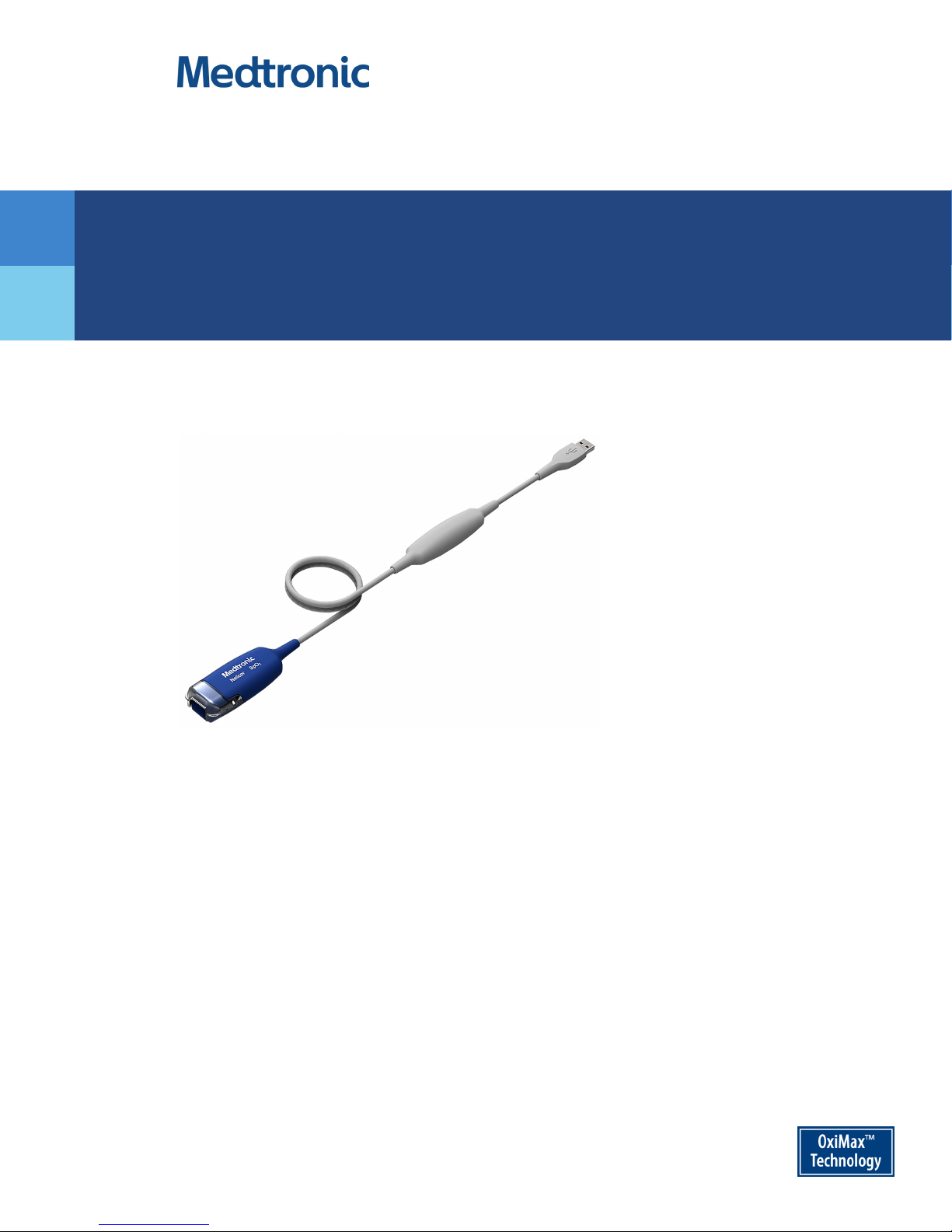
Instructions for Use
TM
Nellcor
OxiCable, USB
305 cm
Page 2

©2017, 2018 Medtronic. All rights reserved. Medtronic and Medtronic logo are trademarks of Medtronic. All other brands are
trademarks of a Medtronic company.
Page 3

Table of Contents
1 Introduction
1.1 Overview . . . . . . . . . . . . . . . . . . . . . . . . . . . . . . . . . . . . . . . . . . . . . . . . . . . . . . . . . . . . . . . . . . . 1-1
1.2 Safety Information . . . . . . . . . . . . . . . . . . . . . . . . . . . . . . . . . . . . . . . . . . . . . . . . . . . . . . . . . . 1-1
1.2.1 Safety Symbols . . . . . . . . . . . . . . . . . . . . . . . . . . . . . . . . . . . . . . . . . . . . . . . . . . . . . . . . . . . . . . . . . . . . . . .1-1
1.2.2 Patient and Operator Safety - General Use . . . . . . . . . . . . . . . . . . . . . . . . . . . . . . . . . . . . . . . . . . . .1-2
1.2.3 System Connection, Compliance, and Interference . . . . . . . . . . . . . . . . . . . . . . . . . . . . . . . . . . . . 1-3
1.2.4 Sensor Use and Performance Considerations . . . . . . . . . . . . . . . . . . . . . . . . . . . . . . . . . . . . . . . . . .1-3
1.2.5 Disposal . . . . . . . . . . . . . . . . . . . . . . . . . . . . . . . . . . . . . . . . . . . . . . . . . . . . . . . . . . . . . . . . . . . . . . . . . . . . . . 1-4
1.3 Technical Assistance . . . . . . . . . . . . . . . . . . . . . . . . . . . . . . . . . . . . . . . . . . . . . . . . . . . . . . . . 1-4
1.3.1 Technical Services . . . . . . . . . . . . . . . . . . . . . . . . . . . . . . . . . . . . . . . . . . . . . . . . . . . . . . . . . . . . . . . . . . . .1-4
1.3.2 Warranty Information . . . . . . . . . . . . . . . . . . . . . . . . . . . . . . . . . . . . . . . . . . . . . . . . . . . . . . . . . . . . . . . . .1-4
2 Product Overview
2.1 Product Description . . . . . . . . . . . . . . . . . . . . . . . . . . . . . . . . . . . . . . . . . . . . . . . . . . . . . . . . . 2-1
2.2 Indications for Use . . . . . . . . . . . . . . . . . . . . . . . . . . . . . . . . . . . . . . . . . . . . . . . . . . . . . . . . . . 2-1
2.3 Monitoring Cable Components . . . . . . . . . . . . . . . . . . . . . . . . . . . . . . . . . . . . . . . . . . . . . . 2-2
2.4 Labeling Symbols . . . . . . . . . . . . . . . . . . . . . . . . . . . . . . . . . . . . . . . . . . . . . . . . . . . . . . . . . . . 2-3
3 Connection
3.1 Connection to a Host Monitoring System . . . . . . . . . . . . . . . . . . . . . . . . . . . . . . . . . . . . . 3-1
3.2 Connection to a Nellcor™ Sensor . . . . . . . . . . . . . . . . . . . . . . . . . . . . . . . . . . . . . . . . . . . . . 3-1
4 Performance Considerations
4.1 Nellcor™ Sensor Performance Considerations . . . . . . . . . . . . . . . . . . . . . . . . . . . . . . . . 4-1
4.2 Electromagnetic Interference . . . . . . . . . . . . . . . . . . . . . . . . . . . . . . . . . . . . . . . . . . . . . . . . 4-2
5 Product Maintenance
5.1 Cleaning . . . . . . . . . . . . . . . . . . . . . . . . . . . . . . . . . . . . . . . . . . . . . . . . . . . . . . . . . . . . . . . . . . . 5-1
5.2 Service and Calibration . . . . . . . . . . . . . . . . . . . . . . . . . . . . . . . . . . . . . . . . . . . . . . . . . . . . . 5-4
6 Accessories
6.1 Nellcor™ Sensor Selection . . . . . . . . . . . . . . . . . . . . . . . . . . . . . . . . . . . . . . . . . . . . . . . . . . . 6-1
7 Theory of Operations
7.1 Theoretical Principles . . . . . . . . . . . . . . . . . . . . . . . . . . . . . . . . . . . . . . . . . . . . . . . . . . . . . . . 7-1
7.2 Automatic Calibration . . . . . . . . . . . . . . . . . . . . . . . . . . . . . . . . . . . . . . . . . . . . . . . . . . . . . . . 7-2
Instructions for Use i
Page 4

7.3 Functional Testers and Patient Simulators . . . . . . . . . . . . . . . . . . . . . . . . . . . . . . . . . . . 7-2
7.4 Functional versus Fractional Saturation . . . . . . . . . . . . . . . . . . . . . . . . . . . . . . . . . . . . . . 7-3
7.5 Measured versus Calculated Saturation . . . . . . . . . . . . . . . . . . . . . . . . . . . . . . . . . . . . . . 7-4
7.6 System Features . . . . . . . . . . . . . . . . . . . . . . . . . . . . . . . . . . . . . . . . . . . . . . . . . . . . . . . . . . . . 7-4
7.6.1 Nellcor™ Sensor Technology . . . . . . . . . . . . . . . . . . . . . . . . . . . . . . . . . . . . . . . . . . . . . . . . . . . . . . . . . .7-4
7.6.2 Data Update Period, Data Averaging, and Signal Processing . . . . . . . . . . . . . . . . . . . . . . . . . . . 7-5
7.6.3 Pulse Rate Delay Alarm Management Parameter . . . . . . . . . . . . . . . . . . . . . . . . . . . . . . . . . . . . . . 7-5
7.6.4 SatSeconds™ Alarm Management Parameter . . . . . . . . . . . . . . . . . . . . . . . . . . . . . . . . . . . . . . . . .7-6
7.7 References . . . . . . . . . . . . . . . . . . . . . . . . . . . . . . . . . . . . . . . . . . . . . . . . . . . . . . . . . . . . . . . . . 7-6
8 Product Specifications
8.1 Physical Characteristics . . . . . . . . . . . . . . . . . . . . . . . . . . . . . . . . . . . . . . . . . . . . . . . . . . . . . 8-1
8.2 Electrical Requirements . . . . . . . . . . . . . . . . . . . . . . . . . . . . . . . . . . . . . . . . . . . . . . . . . . . . . 8-1
8.3 Environmental Conditions . . . . . . . . . . . . . . . . . . . . . . . . . . . . . . . . . . . . . . . . . . . . . . . . . . 8-1
8.4 System Accuracy and Ranges . . . . . . . . . . . . . . . . . . . . . . . . . . . . . . . . . . . . . . . . . . . . . . . . 8-2
8.5 Nellcor™ Sensor Optical Specifications . . . . . . . . . . . . . . . . . . . . . . . . . . . . . . . . . . . . . . . 8-3
8.6 Product Compliance . . . . . . . . . . . . . . . . . . . . . . . . . . . . . . . . . . . . . . . . . . . . . . . . . . . . . . . . 8-3
8.7 Biocompatibility Testing . . . . . . . . . . . . . . . . . . . . . . . . . . . . . . . . . . . . . . . . . . . . . . . . . . . . 8-3
8.8 Manufacturer’s Declaration and Guidance . . . . . . . . . . . . . . . . . . . . . . . . . . . . . . . . . . . 8-4
8.8.1 Electromagnetic Compatibility (EMC) . . . . . . . . . . . . . . . . . . . . . . . . . . . . . . . . . . . . . . . . . . . . . . . . . 8-4
8.8.2 Safety Tests . . . . . . . . . . . . . . . . . . . . . . . . . . . . . . . . . . . . . . . . . . . . . . . . . . . . . . . . . . . . . . . . . . . . . . . . . . . 8-6
8.9 Host Monitoring System Requirements . . . . . . . . . . . . . . . . . . . . . . . . . . . . . . . . . . . . . . 8-6
8.10 Essential Performance . . . . . . . . . . . . . . . . . . . . . . . . . . . . . . . . . . . . . . . . . . . . . . . . . . . . . . 8-7
A Clinical Study
A.1 Overview . . . . . . . . . . . . . . . . . . . . . . . . . . . . . . . . . . . . . . . . . . . . . . . . . . . . . . . . . . . . . . . . . . . A-1
A.2 Methods . . . . . . . . . . . . . . . . . . . . . . . . . . . . . . . . . . . . . . . . . . . . . . . . . . . . . . . . . . . . . . . . . . . A-1
A.3 Study Population . . . . . . . . . . . . . . . . . . . . . . . . . . . . . . . . . . . . . . . . . . . . . . . . . . . . . . . . . . . A-1
A.4 Study Results . . . . . . . . . . . . . . . . . . . . . . . . . . . . . . . . . . . . . . . . . . . . . . . . . . . . . . . . . . . . . . . A-2
A.4.1 Adverse Events or Deviations . . . . . . . . . . . . . . . . . . . . . . . . . . . . . . . . . . . . . . . . . . . . . . . . . . . . . . . . .A-4
A.5 Conclusion . . . . . . . . . . . . . . . . . . . . . . . . . . . . . . . . . . . . . . . . . . . . . . . . . . . . . . . . . . . . . . . . . A-4
ii Instructions for Use
Page 5
1 Introduction
1.1 Overview
This manual provides information for using the Nellcor™ oxicable, USB (the “monitoring cable”).
This manual applies to the following product:
PMC10UB305N
1.2 Safety Information
This section contains important safety information for use of the monitoring cable. Use this
information in conjunction with the safety information specified in the host monitoring system
documentation.
1.2.1 Safety Symbols
Symbol Definition
WARNING
Warnings alert users to potential serious outcomes (death, injury, or adverse events) to
the patient, user, or environment.
Caution
Cautions alert users to exercise appropriate care for safe and effective use of the product.
Note
Notes provide additional guidelines or information.
Table1-1.Safety Symbol Definitions
1-1
Page 6

Introduction
1.2.2 Patient and Operator Safety - General Use
WARNING:
Shock hazard — Do not immerse or wet the monitoring cable or sensor.
WARNING:
Choking hazard — The monitoring cable contains small detachable parts.
WARNING:
Disconnect the monitoring cable, sensor, and monitoring system from the patient during
magnetic resonance imaging (MRI) scanning. Objects containing metal can become dangerous
projectiles when subjected to the strong magnetic fields created by MRI equipment. Also, induced
currents could potentially cause burns.
WARNING:
Do not use the monitoring cable in the presence of flammable anesthetics. This may cause an
explosion or fire.
WARNING:
Do not use a pulse oximetry sensor on the same extremity as a blood pressure cuff or other
constricting instrument. Such usage can cause inaccurate pulse oximetry measurements or a loss
of signal.
WARNING:
Do not use any monitoring cable, monitoring system, sensor, cable, or connector that has a
damaged enclosure or any damaged component. Remove any damaged equipment from service
for inspection by a qualified service technician.
WARNING:
As with all medical equipment, carefully route patient cabling to reduce the possibility of patient
entanglement or strangulation.
WARNING:
Ensure that the monitoring cable is carefully positioned to prevent tripping and entanglement.
Caution:
Federal law (U.S.A.) restricts this device to sale by or on the order of a physician.
1-2 Instructions for Use
Page 7

1.2.3 System Connection, Compliance, and Interference
WARNING:
The monitoring cable may cause radio interference or may disrupt the operation of nearby
equipment. Mitigation for such disruption may require re-orienting or relocating the monitoring
cable or shielding the location.
WARNING:
The use of accessories, sensors, and cables other than those specified may result in inaccurate
readings and increased EMI emissions of the monitoring cable.
WARNING:
EMI disruption can cause erratic readings, cessation of operation, or other incorrect functioning.
Caution:
This device has been tested and found to comply with the limits for medical devices related to IEC
60601-1-2: 2007 for Class B Emissions. These limits are designed to provide reasonable protection
against harmful interference in a typical medical installation.
Safety Information
Caution:
Anyone who connects the monitoring cable to a host monitoring system is configuring a medical
system and, therefore, is responsible for ensuring the system complies with the Requirements for
Medical Electrical Systems IEC/EN 60601-1:2005 and electromagnetic compatibility IEC/EN 606011-2:2007.
Caution:
Do not connect the monitoring cable’s USB connector to anything other than a compatible USB 2.0
host device.
1.2.4 Sensor Use and Performance Considerations
WARNING:
Certain physical conditions may affect calculation of SpO
include, but are not limited to: dysfunctional hemoglobin, intravascular dyes, low perfusion, and
darkly pigmented skin. Refer to Nellcor™ Sensor Performance Considerations, page 4-1.
Caution:
Use only Medtronic-approved sensors when connecting to the sensor port. Connecting any other
sensor influences the accuracy of sensor data, which may lead to adverse results.
and pulse rate. These conditions
2
Instructions for Use 1-3
Page 8

Introduction
1.2.5 Disposal
Caution:
Dispose of the monitoring cable in accordance with local requirements and regulations.
1.3 Technical Assistance
1.3.1 Technical Services
For technical information and assistance, if unable to correct a problem while using the monitoring cable, or to order parts, contact Medtronic or a local Medtronic representative.
Medtronic Technical Services: Patient Monitoring
15 Hampshire Street
Mansfield, MA 02048 USA
1.800.635.5267, 1.925.463.4635 (toll)
or contact a local Medtronic representative
www.medtronic.com
When calling Medtronic or a local Medtronic representative, have the monitoring cable serial
number available.
1.3.2 Warranty Information
To obtain information, contact Medtronic or a local Medtronic representative. See Technical Ser-
vices, page 1-4.
Purchase of this instrument confers no express or implied license under any Medtronic patent to
use that instrument with any sensor not manufactured or licensed by Medtronic.
1-4 Instructions for Use
Page 9

2 Product Overview
2.1 Product Description
When used with a host monitoring system, the Nellcor™ oxicable, USB (the “monitoring cable”)
provides continuous non-invasive monitoring of functional oxygen saturation of arterial hemoglobin (SpO
cable relies on unique oximetry technology and design to provide hospitals, clinicians, and caregivers with accurate, timely data.
The monitoring cable provides the following patient data to the host monitoring system:
• Arterial blood oxygen saturation (SpO
tive to the sum of oxyhemoglobin and deoxyhemoglobin.
• Pulse rate (PR) - Detected pulsations per minute.
• Plethysmographic waveform (Pleth) - Visual waveform representing detected pulsations. (Non-
normalized)
) and pulse rate, as measured by Nellcor™ pulse oximetry sensors. The monitoring
2
) - Functional measure of oxygenated hemoglobin rela-
2
• Operating status - Alarm conditions and operational status.
2.2 Indications for Use
The Nellcor™ OxiCable, USB is indicated for prescription use only for spot check or continuous
non-invasive monitoring of functional oxygen saturation of arterial hemoglobin (SpO
pulse rate. It is intended for use with neonatal, pediatric, and adult patients during both no
motion and motion conditions and for patients who are either well or poorly perfused, in hospitals and hospital-type facilities.
Note:
• Hospital use typically includes such areas as the intensive care unit (ICU), neonatal intensive care unit
(NICU), operating room (OR), post-anesthesia care unit (PACU), emergency department, and
medical/surgical general care floor (GCF).
• Hospital-type facilities include step-down units and long-term care facilities.
Use with any particular patient requires the selection of an appropriate Nellcor™ sensor. See Nellcor™
Sensor Selection, page 6-1.
) and
2
2-1
Page 10
Product Overview
Monitoring Cable Components
2.3
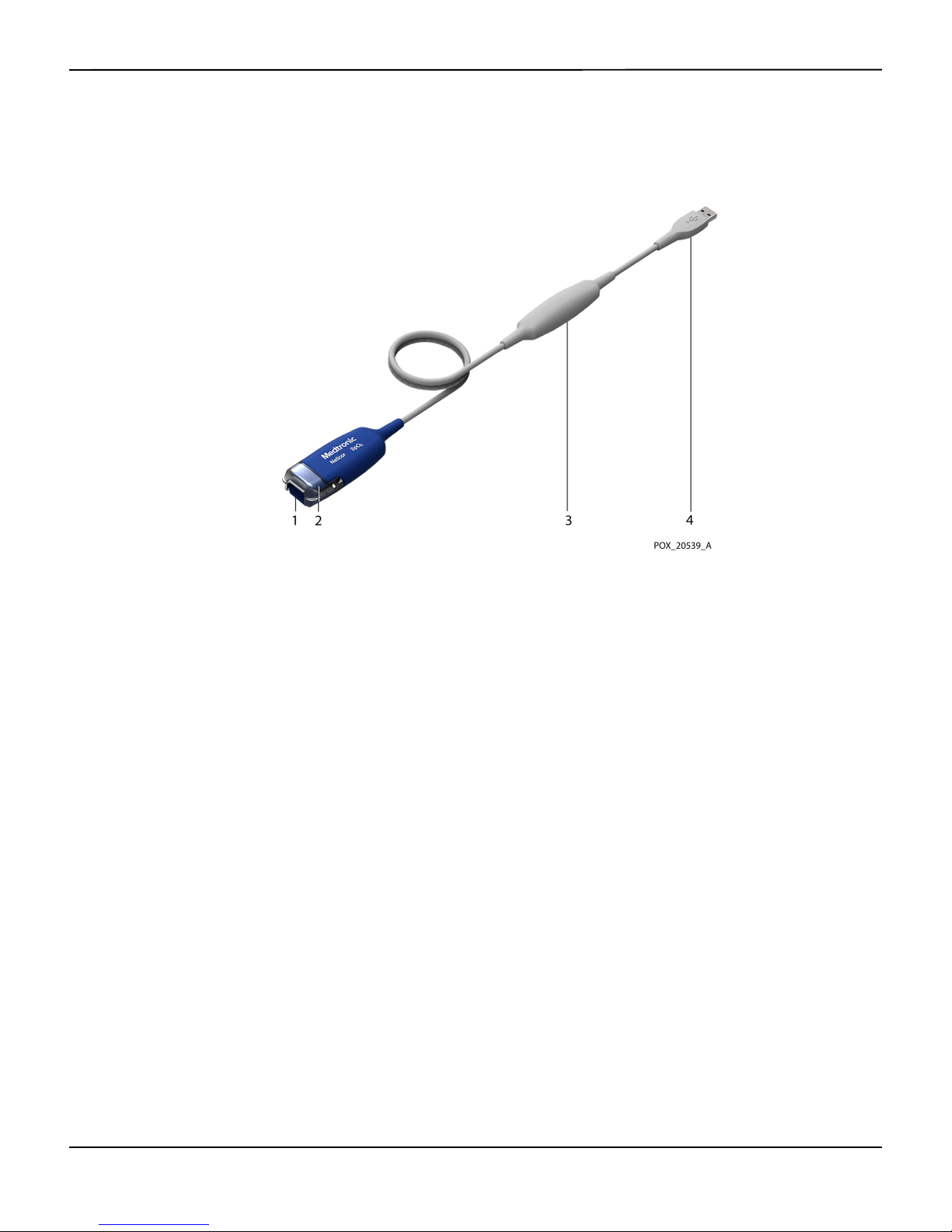
Figure2-1.Monitoring Cable Components
1 Sensor Port
(to Nellcor™ Sensor)
2 Sensor Latch 4 USB Connector
3 Isolation Module
(to Host Monitoring System)
2-2 Instructions for Use
Page 11
Labeling Symbols
2.4
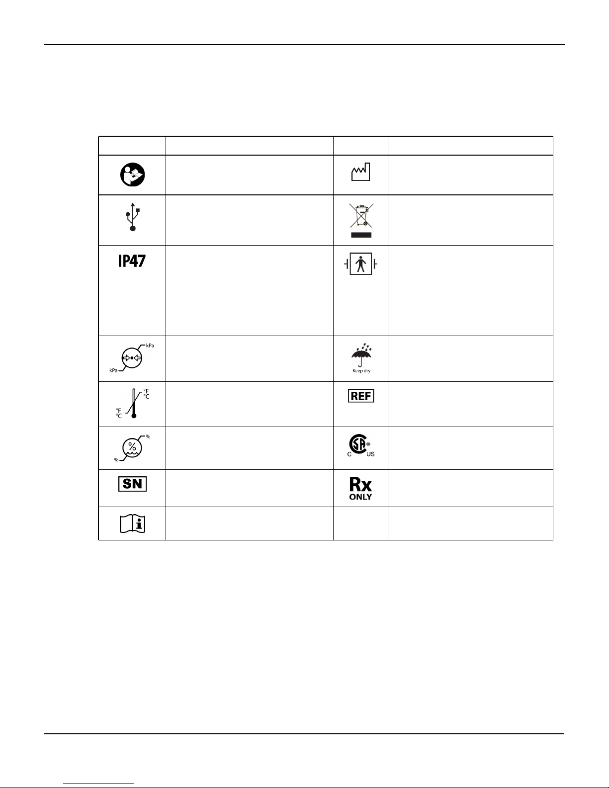
Symbol Description Symbol Description
Must consult instructions for use Date of manufacture
Universal Serial Bus (USB) connector Proper waste disposal for electrical and
Labeling Symbols
Table2-1.Labeling Symbols
electronic equipment
Protection against particulate and fluid
ingress:
Protected against solid objects greater than
1mm.
Protected against the effects of submersion
in water up to 1 meter deep for up to 30
minutes.
Atmospheric pressure limitations (see Envi-
ronmental Conditions, page 8-1)
Temperature limitations (see Environmental
Conditions, page 8-1)
Humidity limitations (see Environmental
Conditions, page 8-1)
Serial number Prescription only
Consult instructions for use
Type BF applied part: Nellcor™ sensor and
sensor cable
Defibrillator proof
Keep dry
Catalog number
CSA – Canadian Standards Association certification mark
Instructions for Use 2-3
Page 12

Product Overview
Page Left Intentionally Blank
2-4 Instructions for Use
Page 13
3 Connection
3.1 Connection to a Host Monitoring System
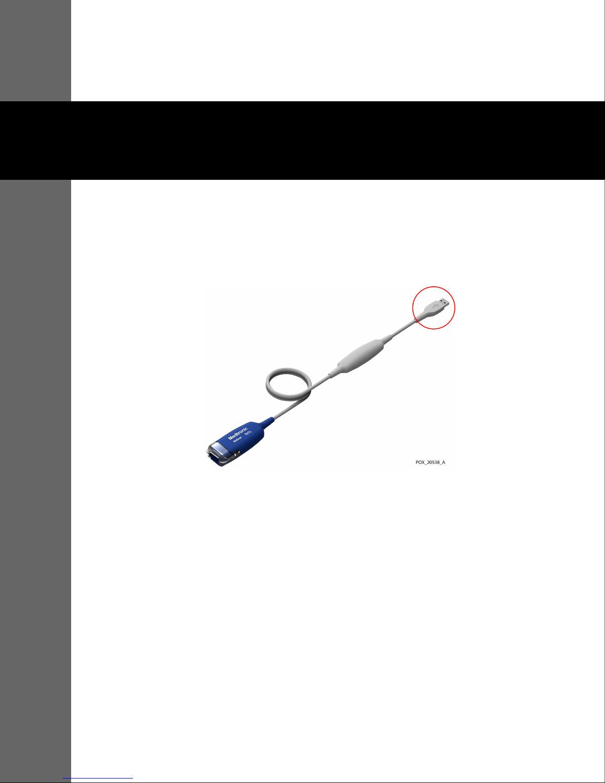
To connect the Nellcor™ oxicable, USB (the “monitoring cable”) to a host monitoring system,
insert the monitoring cable’s USB connector into a compatible USB port on the host system.
Figure3-1.USB Connector on Monitoring Cable
Note:
The monitoring cable derives power from the host monitoring system. The monitoring cable has no
power switch. To ensure that power is removed from the monitoring cable, disconnect it from the host
monitoring system.
3.2 Connection to a Nellcor™ Sensor
Prior to using a Nellcor™ sensor with the monitoring cable:
• See Nellcor™ Sensor Selection, page 6-1 for information about selecting the appropriate sensor for the
patient.
• Read the Instructions for Use accompanying the sensor.
• See Nellcor™ Sensor Performance Considerations, page 4-1 for information about optimizing the per-
formance of the sensor and monitoring cable during patient use.
3-1
Page 14

Connection
To connect a Nellcor™ sensor to the monitoring cable:
1. Open the latch at the end of the monitoring cable’s sensor port and firmly insert the sensor connector.
The connector is keyed so that it fits correctly in one orientation only.
Figure3-2.Inserting Sensor Connector
2. Snap the latch over the sensor connector. When the sensor connector is seated properly, the latch
should close completely over the connector.
Figure3-3.Latch Closed over Sensor Connector
3-2 Instructions for Use
Page 15

4 Performance Considerations
4.1 Nellcor™ Sensor Performance Considerations
A variety of conditions can cause inaccurate sensor measurements or cause the loss of the pulse
signal:
• Incorrect application of the recommended sensor
• Sensor applied too tightly
• Placement of the sensor on an extremity with a blood pressure cuff, arterial catheter, or intravascular
line
• Failure to cover the sensor site with material that blocks light when operating under bright light condi-
tions
High ambient light sources such as surgical lights (especially those with a xenon light source),
bilirubin lamps, fluorescent lights, infrared heating lamps, and direct sunlight can interfere with
sensor performance. To prevent interference from ambient light, ensure the sensor is properly
applied, and cover the sensor with opaque material.
Additional possible patient conditions may also influence measurements:
• Anemia — Anemia causes decreased arterial oxygen content. Although SpO
normal, an anemic patient may be hypoxic. Correcting anemia can improve arterial oxygen content.
The monitoring cable may fail to provide an SpO
• Dysfunctional hemoglobins — Dysfunctional hemoglobins such as carboxyhemoglobin, methemo-
globin, and sulfhemoglobin are unable to carry oxygen. SpO
reading if hemoglobin levels fall below 5 gm/dl.
2
readings may appear normal; howev-
2
er, a patient may be hypoxic because less hemoglobin is available to carry oxygen. Further
assessment beyond pulse oximetry is recommended.
• Arterial occlusion proximal to the sensor
• Poor peripheral perfusion
• Excessive patient movement
• Venous pulsations
• Dark skin pigment
readings may appear
2
4-1
Page 16

Performance Considerations
Intravascular dyes, such as indocyanine green or methylene blue
•
• Externally applied coloring agents (nail polish, dye, pigmented cream)
• Defibrillation
4.2 Electromagnetic Interference
Because of the proliferation of radio frequency transmitting equipment and other sources of electrical
noise in health care environments (for example, electrosurgical units, cellular phones, mobile two-way
radios, electrical appliances, and high-definition television), it is possible that high levels of such interference due to close proximity or strength of a source might result in disruption of monitoring cable
performance.
The monitoring cable is designed for use in environments in which electromagnetic interference
might obscure the client’s pulse. During such interference, measurements may seem inappropriate or the monitoring cable may not seem to operate correctly. EMI disruption can cause erratic
readings, cessation of operation, or other incorrect functioning. If this occurs, survey the site of use
to determine the source of this disruption, and take the listed actions to eliminate the source.
• Turn equipment in the vicinity off and on to isolate the interfering equipment.
• Reorient or relocate the interfering equipment.
• Increase the separation between the interfering equipment and the monitoring cable.
The monitoring cable can radiate radio frequency energy and, if not installed and used in accordance
with these instructions, may itself cause harmful interference with other susceptible devices in the
vicinity.
4-2 Instructions for Use
Page 17

5 Product Maintenance
5.1 Cleaning
For surface cleaning of the Nellcor™ oxicable, USB (the “monitoring cable”), follow the procedure below.
Note:
Before attempting to clean a Nellcor™ sensor, read the Instructions for Use enclosed with the sensor. Each
sensor model has cleaning instructions specific to that sensor.
Note:
For cleaning instructions for the host monitoring system, refer to the host system's operators manual.
Materials
• Paper towels
• Soft, lint-free cloths
• Water (tap water is acceptable)
• Cleaning agent:
Procedure
Note:
Ensure at least 30 seconds of contact time between the cleaning agent and all surfaces being cleaned.
To clean the monitoring cable:
1. Power off the host monitoring system.
2. If a sensor is connected to the monitoring cable, disconnect the sensor.
3. Moisten (but do not saturate) a paper towel with water. Remove excess water as necessary.
– Isopropyl alcohol, maximum 60% by weight, or
– Bleach: Mix 10 parts water to 1 part 5.25% bleach to create an 0.5% bleach concentration
5-1
Page 18

Product Maintenance
4. Starting at the sensor port end of the monitoring cable, use the moistened paper towel to soften and
loosen any bulky soils on the exterior of the monitoring cable, then wipe them off.
5. Moisten (but do not saturate) a clean lint-free cloth with one of the cleaning agents listed in Materials,
page 5-1.
Note:
Do not spray the cleaning agent into the sensor port.
Note:
Do not clean the metal USB connector with the cleaning agent. The cleaning agent can damage the
connector.
6. Wipe down all external surfaces of the monitoring cable, removing all visible soil, ensuring not to wipe
the USB connector. Begin at the sensor port end of the cable and work toward the opposite end. Pay
special attention to the areas shown in the following figure.
Figure5-1.Check These Areas for Soil
7. If there is soil beneath the sensor latch, clean the latch and area under the latch as follows:
Figure5-2.Check These Areas for Soil When Latch is Removed
a. With the sensor latch in the open (up) position, gently pull one side of the latch away from the
body of the monitoring cable until the latch disengages from the pegs on both sides.
b. Moisten (but do not saturate) a paper towel with water. Remove excess water as necessary.
5-2 Instructions for Use
Page 19

Cleaning
c. Use the moistened paper towel to soften and loosen any bulky soils on the latch and in the area
under the latch, then wipe them off.
d. Moisten (but do not saturate) a clean lint-free cloth with one of the cleaning agents listed in Mate-
rials, page 5-1.
e. Use the moistened cloth to remove all visible soil from the latch and area under the latch, with
special attention to the areas shown in Figure5-2.
f. Rinse the latch in tap water until all residual cleaning agent has been removed.
g. Use a clean lint-free cloth to dry the latch.
h. Wipe the surfaces of the monitoring cable where the latch was attached until all residual cleaning
agent has been removed. See Figure5-3.
Figure5-3.Ensure all of These Areas are Clean When Latch is Removed
i. Use a clean lint-free cloth to dry the area where the latch was attached.
Note:
Do not use pressurized air or gas to dry inside the sensor port.
j. If visible soil remains, repeat the cleaning process.
k. Ensure all areas are dry before reattaching the sensor latch.
l. Replace the sensor latch by positioning it directly in front of the sensor port in the closed position.
Slide the latch over the sensor port until it snaps into position on the pegs on both sides of the
sensor port body. Ensure that the latch opens and closes freely over the sensor port. If the latch is
damaged, contact Medtronic (see Technical Services, page 1-4).
8. Moisten a clean lint-free cloth with water and wipe the monitoring cable until all residual cleaning
agent has been removed.
9. Use a clean lint-free cloth to dry the monitoring cable.
Note:
Do not use excessive drying techniques, such as oven, forced heat, or sun drying.
10. If visible soil remains on the monitoring cable, repeat the cleaning process.
Instructions for Use 5-3
Page 20

Product Maintenance
Note:
Ensure that the monitoring cable is completely dry before connecting a sensor and returning it to patient
use.
5.2 Service and Calibration
Note:
There are no user-serviceable parts inside the monitoring cable. Users may not modify any components of
the monitoring cable.
Periodically verify the functionality of the monitoring cable by following the procedures outlined
in the SRC-MAX Pulse Oximetry Functional Tester Technical Manual. Have a qualified service technician perform these procedures prior to initial installation in a clinical setting.
The monitoring cable requires no calibration.
5-4 Instructions for Use
Page 21

6 Accessories
6.1 Nellcor™ Sensor Selection
When selecting a Nellcor™ sensor, consider the patient’s weight and activity level, the adequacy
of perfusion, the available sensor sites, the need for sterility, and the anticipated duration of
monitoring. Use the recommended sensor’s Instructions for Use to guide sensor selection, or
contact Medtronic or a local Medtronic representative.
Table6-1.Nellcor™ Sensor Models
Nellcor™ Sensor SKU
Nellcor™ Preemie SpO
Nellcor™ Neonatal SpO
Nellcor™ Adult SpO
Sensor, non-adhesive (Single-patient use) SC-PR
2
Sensor, non-adhesive (Single-patient use) SC-NEO
2
Sensor, non-adhesive (Single-patient use) SC-A
2
Nellcor™ Adult-Neonatal SpO
Nellcor™ Pediatric-Infant SpO
Nellcor™ Pediatric SpO
Sensor, Two Piece (Sterile, single-use only) P
2
Nellcor™ Neonatal-Adult SpO
Nellcor™ Infant SpO
Nellcor™ Adult SpO
Sensor, Two Piece (Sterile, single-use only) I
2
Sensor, Two Piece (Sterile, single-use only) A
2
Nellcor™ Neonatal-Adult SpO
Nellcor™ Infant SpO
Nellcor™ Pediatric SpO
Nellcor™ Adult SpO
Nellcor™ Adult SpO
Nellcor™ Adult XL SpO
Sensor (Sterile, single-use only) MAXI
2
Sensor (Sterile, single-use only) MAXP
2
Sensor (Sterile, single-use only) MAXA
2
Nasal Sensor (Sterile, single-use only) MAXR
2
Sensor (Sterile, single-use only) MAXAL
2
Sensor with Wraps (Reusable with adhesive) OXI-A/N
2
Sensor with Wraps (Reusable with adhesive) OXI-P/I
2
Sensor, Two Piece (Sterile, single-use only) N
2
Sensor (Sterile, single-use only) MAXN
2
Nellcor™ Forehead SpO
Nellcor™ Adult SpO
Nellcor™ SpO
Sensor, Multi-site Reusable (Nonsterile) D-YS
2
Sensor (Sterile, single-use only) MAXFAST
2
Sensor, Reusable (Nonsterile) DS100A
2
6-1
Page 22

Accessories
Table6-1.Nellcor™ Sensor Models (Continued)
Nellcor™ Sensor SKU
Nellcor™ SpO2 Ear Clip, Reusable (Nonsterile) D-YSE
Nellcor™ Pediatric SpO
Nellcor™ Flexible SpO
Nellcor™ Flexible SpO
Sensor Clip, Reusable (Nonsterile) D-YSPD
2
Sensor, Reusable FLEXMAX
2
Sensor, Reusable, Small FLEXMAX-P
2
Contact Medtronic for sensor accuracy information regarding all applicable Nellcor™ sensors.
6-2 Instructions for Use
Page 23

7 Theory of Operations
7.1 Theoretical Principles
The Nellcor™ oxicable, USB (the “monitoring cable”) uses pulse oximetry to measure functional
oxygen saturation in the blood [1]. Pulse oximetry works by applying a Nellcor™ sensor to tissue
regions with rich presence of capillaries and arterioles, such as a finger or toe [2]. The sensor
contains a dual light source and a photodetector [2] [3].
Bone, tissue, pigmentation, and venous vessels normally absorb a constant amount of light over
time. The vascular bed normally pulsates and absorbs variable amounts of light during the pulsations. The ratio of light absorbed is translated into a measurement of functional oxygen saturation (SpO
Ambient conditions, sensor application, and patient conditions can influence the ability of the
monitoring cable to accurately measure SpO
Pulse oximetry is based on two physical principles: oxyhemoglobin and deoxyhemoglobin
differ in their absorption of red and infrared light (measured using spectrophotometry), and the
volume of arterial blood in tissue (and hence, light absorption by that blood) changes during
the pulse (registered using plethysmography) [5]. A monitoring system determines SpO
passing red and infrared light into a vascular bed and measuring changes in light absorption
during the pulsatile cycle. Red and infrared low-voltage light-emitting diodes (LED) in the
sensor serve as light sources; a photo diode serves as the photo detector [2] [3].
) [2] [3].
2
2
[4].
2
by
Since oxyhemoglobin and deoxyhemoglobin differ in light absorption, the amount of red and
infrared light absorbed by blood is related to hemoglobin oxygen saturation [2].
The monitoring cable uses the pulsatile nature of arterial flow to identify the oxygen saturation
of arterial hemoglobin. During systole, a new pulse of arterial blood enters the vascular bed, and
blood volume and light absorption increase. During diastole, blood volume and light absorption reach their lowest point. The monitoring cable bases its SpO
ence between maximum and minimum absorption (measurements at systole and diastole). By
doing so, it focuses on light absorption by pulsatile arterial blood, eliminating the effects of nonpulsatile absorbers such as tissue, bone, and venous blood [2] [6].
measurements on the differ-
2
7-1
Page 24

Theory of Operations
Automatic Calibration
7.2
Because light absorption by hemoglobin is wavelength dependent and because the mean wavelength of LEDs varies, a monitoring system must know the mean wavelength of the sensor's red
LED to accurately measure SpO
2
[2].
During monitoring, the monitoring cable's software selects coefficients that are appropriate for
the wavelength of that individual sensor's red LED; these coefficients are then used to determine
[2].
SpO
2
Additionally, to compensate for differences in tissue thickness, the light intensity of the sensor's
LEDs is adjusted automatically [2].
Note:
During certain automatic calibration functions, the monitoring system may briefly display a flat line on the
plethysmographic waveform. This is a normal operation and does not require any user intervention.
7.3 Functional Testers and Patient Simulators
Some models of commercially available bench top functional testers and patient simulators can
be used to verify the proper functionality of Medtronic Nellcor™ monitoring systems, sensors, and
cables. Reference the individual testing device's operator's manual for the procedures specific to
the model of tester used. While such devices may be useful for verifying that the sensor, cabling,
and monitoring system are functional, they are incapable of providing the data required to properly evaluate the accuracy of a system's SpO
measurements. Fully evaluating the accuracy of the
2
SpO2 measurements requires, at a minimum, accommodating the wavelength characteristics of
the sensor and reproducing the complex optical interaction of the sensor and the patient's tissue.
These capabilities are beyond the scope of known bench top testers. SpO
measurement accura-
2
cy can only be evaluated in vivo by comparing monitoring system readings with values traceable
to SaO
measurements obtained from simultaneously sampled arterial blood using a laboratory
2
CO-oximeter [6].
Many functional testers and patient simulators have been designed to interface with the monitoring system's expected calibration curves and may be suitable for use with monitoring systems
and/or sensors. However, not all functional testers and patient simulators are compatible for use
with the OxiMax™ digital calibration system [6].
While this will not affect use of the simulator for verifying system functionality, displayed SpO
2
measurement values may differ from the setting of the test device. For a properly functioning
monitoring system, this difference will be reproducible over time and from monitoring system to
monitoring system within the performance specifications of the test device [6].
7-2 Instructions for Use
Page 25

Functional versus Fractional Saturation
Functional versus Fractional Saturation
7.4
This monitoring cable measures functional saturation where oxygenated hemoglobin is
expressed as a percentage of the hemoglobin that can transport oxygen. It does not detect significant amounts of dysfunctional hemoglobin, such as carboxyhemoglobin or methemoglobin.
In contrast, hemoximeters, report fractional saturation where oxygenated hemoglobin is
expressed as a percentage of all measured hemoglobin, including measured dysfunctional
hemoglobins. To compare functional saturation measurements to those from a monitoring
system that measures fractional saturation, fractional measurements must be converted using the
following equation:
100+–=
Functional saturation %carboxyhemoglobin
Fractional saturation %methemoglobin
Instructions for Use 7-3
Page 26

Theory of Operations
Measured versus Calculated Saturation
7.5
When calculating saturation from a blood gas partial pressure of oxygen (PO2), the calculated
value may differ from the SpO2 measurement of a monitoring system. This usually occurs when
saturation calculations exclude corrections for the effects of variables such as pH, temperature,
the partial pressure of carbon dioxide (PCO
PO2 and SpO2 as shown in the following figure.
), and 2,3-DPG, that shift the relationship between
2
Figure7-1.Oxyhemoglobin Dissociation Curve
1 Saturation (%) Axis 3 Increased pH; Decreased temperature,
PCO
, and 2,3-DPG
2
2PO
(mmHg) Axis 4 Decreased pH; Increased temperature,
2
System Features
7.6
7.6.1 Nellcor™ Sensor Technology
PCO
, and 2,3-DPG
2
Nellcor™ sensors are specifically designed for use with particular monitoring systems. Nellcor™
sensors are identified by the Nellcor™ logo on the plug. All Nellcor™ sensors with OxiMax™ technology contain a memory chip carrying information about the sensor which the monitoring cable
requires for correct operation, including the sensor's calibration data, model type, troubleshooting codes, and error detection data [7].
Medtronic's unique oximetry architecture enables several distinctive features. When an OxiMax™
sensor is connected to the monitoring cable, the monitoring cable reads the information from the
7-4 Instructions for Use
Page 27

System Features
sensor’s memory chip, ensures it is error free, and then loads the sensor data prior to monitoring
for new information [7].
Any monitoring system containing OxiMax™ technology uses calibration data contained in the
sensor to calculate the patient's SpO
. With sensor calibration, the accuracy of many sensors is
2
improved over non-calibrated sensors, since the calibration coefficients can be tailored to each
sensor [7].
7.6.2 Data Update Period, Data Averaging, and Signal Processing
The advanced signal processing of the OxiMax™ algorithm automatically extends the amount of
data required for measuring SpO
and pulse rate depending on the measurement conditions.
2
The OxiMax™ algorithm automatically extends the dynamic averaging time required beyond
seven seconds during degraded or difficult measurement conditions caused by low perfusion,
signal artifact, ambient light, electrocautery, other interference, or a combination of these factors,
which results in an increase in the dynamic averaging. If the resulting dynamic averaging time
exceeds 20 seconds for SpO
, the monitoring cable reports a pulse search condition to the mon-
2
itoring system while continuing to update SpO2 and pulse rate values every second. If the
dynamic averaging time exceeds 25 seconds, the monitoring cable reports a low-priority Extend-
ed Update alarm condition to the monitoring system.
As such measurement conditions extend, the amount of data required may continue to increase.
If the dynamic averaging time reaches 40 seconds for SpO
high priority alarm state results: the monitoring cable reports a Pulse Timeout alarm condition to
the monitoring system and reports a zero saturation indicating a loss-of-pulse condition.
7.6.3 Pulse Rate Delay Alarm Management Parameter
Note:
This parameter is available via the monitoring cable but may be optionally implemented on the host
monitoring system.
The monitoring cable also monitors pulse rate by determining the number of cardiac cycles over
a one minute time period. With traditional alarm management, upper and lower alarm limits are
set for monitoring pulse rate. When pulse rates fluctuate near an alarm limit, alarms trigger with
each violation. Pulse Rate Delay allows a period of threshold violation before the pulse rate alarm
sounds. Thus, it helps distinguish clinically significant events from minor and brief pulse rate limit
violations that may result in nuisance alarms.
, and/or 50 seconds for pulse rate, a
2
Instructions for Use 7-5
Page 28

Theory of Operations
7.6.4 SatSeconds™ Alarm Management Parameter
Note:
This parameter is available via the monitoring cable but may be optionally implemented on the host
monitoring system.
The monitoring cable monitors the percentage of hemoglobin binding sites saturated with
oxygen in the blood. With traditional alarm management, upper and lower alarm limits are set to
alarm at specific SpO
each time it violates the alarm threshold. SatSeconds monitors both degree and duration of
desaturation when the SpO
When the SatSeconds index crosses a set threshold, the alarm annunciates. Thus, the SatSeconds
parameter helps distinguish clinically significant events from minor and brief desaturations that
may result in nuisance alarms.
7.7 References
levels. When the SpO2 level fluctuates near an alarm limit, the alarm sounds
2
level crosses the alarm limits as an index of desaturation severity.
2
[1] J. Toffaletti and W. G. Zijlstra, "Misconceptions in Reporting Oxygen Saturations," Anesthesia & Analgesia, vol. 105, no. 6,
pp. S5 - S10, December 2007.
[2] P. D. Mannheimer, "Light-Tissue Interaction of Pulse Oximetry," Anesthesia & Analgesia, vol. 105, no. 6, pp. S11-S17,
December 2007.
[3] K. K. Tremper, "Pulse Oximetry," Chest Journal, vol. 95, no. 4, pp. 713 - 715, April 1989.
[4] P. B. Batchelder and D. M. Raley, "Maximizing the Laboratory Setting for Testing Devices and Understanding Statistical
Output in Pulse Oximetry," Anesthesia & Analgesia, vol. 105, no. 6, pp. S85 - S94, 2007.
[5] T. Aoyagi and M. K, "Pulse Oximetry: Its invention, contribution to medicine and future tasks," Anesthesia & Analgesia, vol.
94, pp. S1 - S3, 2002.
[6] BS EN ISO 80601-2-61: 2011, Medical Electrical Equipment: Particular requirements for basic safety and essential performance
of pulse oximeter equipment.
[7] Nellcor Technical Staff, A Technology Overview of the Nellcor OxiMax Pulse Oximetry System: 0379-1203, Whitepaper, 2003.
7-6 Instructions for Use
Page 29

8 Product Specifications
8.1 Physical Characteristics
Weight 160 ± 16 g (0.35 ± 0.03 lbs.)
Length 305 ± 5 cm (10 ± 0.16 ft.)
8.2 Electrical Requirements
Power Requirements USB host power supply: 5.0V ±5% DC power input
Consumes maximum 250mW (average power) with no fault conditions
Consumes typical 40mA ±10% current (5V input ±5%)
USB Standard USB 2.0 full-speed compliant
8.3 Environmental Conditions
Operating Transport and Storage
Temperature 5ºC to 40ºC
(41ºF to 104ºF)
Altitude/Atmospheric
Pressure
Relative Humidity 15% to 95% non-condensing 15% to 95% non-condensing
-500 m to 4,000 m
(1075 hPa to 616 hPa)
-40ºC to 70ºC
(-40ºF to 158ºF)
-500 m to 5,572 m
(1075 hPa to 500 hPa)
8-1
Page 30

Product Specifications
System Accuracy and Ranges
8.4
The monitoring cable has the capability to detect physiological alarm conditions using SpO2
accuracy, pulse rate accuracy, and alarm limit conditions.
Table8-1.System Measurement Ranges
Measurement Range
SpO
2
1% to 100%
Pulse Rate 20 to 300 beats per minute (bpm)
Perfusion 0.03% to 20%
Table8-2.System Accuracy Ranges
Accuracy
Saturation
Adult2,
Neonate
Adult and Neonate Low Sat
Low Perfusion
Adult and Neonate with Motion
1
3
4, 5
2, 3, 4
6
2, 7
70 to 100% ±2 digits
70 to 100% ±2 digits
60 to 80% ±3 digits
70 to 100% ±2 digits
70 to 100% ±3 digits
Pulse Rate
2, 3
and Neonate
Adult
Low Perfusion
Adult and Neonate with Motion
1. Saturation accuracy varies by sensor type. Contact Medtronic for sensor accuracy information.
2. Accuracy specifications were validated using measurements of healthy non-smoking adult volunteers during controlled hypoxia studies spanning the specified saturation ranges. Subjects were recruited from the local population and comprised
both men and women ranging in age from 18-50 years old, and spanned a range of skin pigmentations. Pulse oximeter SpO
readings were compared to SaO2 values of drawn blood samples measured by hemoximetry. All accuracies are expressed
as ±1 SD. Because pulse oximeter equipment measurements are statistically distributed, about two-thirds of the measurements can be expected to fall in this accuracy (A
3. Adult specifications are shown for OxiMax™ MAXA and MAXN sensors with the pulse oximeter.
4. Neonate specifications are shown for OxiMax™ MAXN sensors with the pulse oximeter.
5. Clinical functionality has been demonstrated on a population of hospitalized neonate patients. The observed SpO
was 2.5% in a study of 42 patients with ages of 1 to 23 days, weight from 750 to 4,100 grams, and 61 observations made
spanning a range of 77% to 98% SaO
6. Specification applies to monitoring cable performance. Reading accuracy in the presence of low perfusion (detected IR pulse
modulation amplitude 0.03% - 1.5%) was validated using signals supplied by a patient simulator. SpO
were varied across the monitoring range over a range of weak signal conditions and compared to the known true saturation
and pulse rate of the input signals.
7. Motion performance was validated during a controlled hypoxia blood study over an SaO2 span of 70% to 98.9% and a convenience-sample heart rate range of 41-105 bpm. Subjects performed rubbing and tapping movements 1-2 cm in amplitude
with aperiodic intervals (randomly changing) with a random variation in frequency between 1-4 Hz. The average percent
modulation during quiescent periods was 3.28, during motion 4.05. Motion performance over the entire specified pulse rate
range was validated using synthetic signals from a patient simulator that comprised representative cardiac and signal artifact
components. Applicability: OxiMax™ MAXA, MAXAL, MAXP, MAXI, and MAXN sensors.
4, 5
6
2, 7
.
2
20 to 250 bpm ±3 digits
20 to 250 bpm ±3 digits
20 to 250 bpm ±5 digits
) range.
RMS
accuracy
2
and pulse rate values
2
2
8-2 Instructions for Use
Page 31

Nellcor™ Sensor Optical Specifications
8.5
LED Wavelength Maximum Output Power
Red: Approximately 650 to 670 nm 3.0 mW
Infrared: Approximately 880 to 910 nm 4.0 mW
Power Dissipation
52.5 mW
Wavelength range can be especially useful to clinicians.
8.6 Product Compliance
Equipment Classification USB-Powered Pulse Oximeter
IEC CISPR 11, Group 1, Class B
IEC/EN 80601-2-61:2011
CAN/CSA-C22.2 No. 60601-1:14
IEC 60601-1:2005/AMD1:2012
Nellcor™ Sensor Optical Specifications
Patient Isolation 1.5 kV
Degree of Protection Against Electrical Shock Defibrillation-Proof Type BF Applied Part
Mode of Operation Continuous
Electromagnetic Compatibility IEC 60601-1-2:2007
IEC 60601-1-2:2014
Ingress Protection IP47
Degree of Safety Not suitable for use in the presence of flammable anesthetics
Biocompatibility Testing
(Monitoring Cable)
8.7 Biocompatibility Testing
ISO 10993-1, Biological Evaluation of Medical Devices, Part 1:
Evaluation and Testing
Biocompatibility testing has been conducted on the monitoring cable in compliance with ISO
10993-1, Biological Evaluation of Medical Devices, Part 1: Evaluation and Testing. The monitoring
cable has passed the recommended biocompatibility testing and is therefore in compliance with
ISO 10993-1.
Instructions for Use 8-3
Page 32

Product Specifications
Manufacturer’s Declaration and Guidance
8.8
8.8.1 Electromagnetic Compatibility (EMC)
The monitoring cable is suitable for prescription use only in the specified electromagnetic environments, in accordance with the IEC 60601-1-2:2014 standard. The monitoring cable requires special precautions during installation and operation for electromagnetic compatibility. In particular, the use of
nearby mobile or portable communications equipment may influence monitoring cable performance.
Electromagnetic Emissions
Table8-3.Electromagnetic Emissions Guidelines and Compliance
Guidance and Manufacturer’s Declaration—Electromagnetic Emissions
The monitoring cable is intended for use in the electromagnetic environment specified
below. The customer or the user of the monitoring cable should assure that it is used in such
(IEC/EN 60601-1-2:2014)
an environment.
Emissions Test Compliance
RF emission
CISPR 11
EN 55011
Electromagnetic Immunity
Table8-4.Electromagnetic Immunity Guidelines and Compliance
Guidance and Manufacturer’s Declaration—Electromagnetic Immunity
The monitoring cable is intended for use in the electromagnetic environment specified below.
The customer or the user of the monitoring cable should assure that it is used in such an environment.
Immunity Test IEC/EN 60601-1-2
Electrostatic discharge
(ESD)
IEC/EN 61000-4-2
Test Level
± 8 kV contact
± 15 kV air
Class B
(IEC/EN 60601-1-2:2014)
Compliance
Level
± 8 kV contact
± 15 kV air
Electromagnetic Environment
Guidance
Floor should be wood, concrete, or
ceramic tile. If floors are covered with
synthetic material, the relative humidity should be at least 30%.
Power frequency (50/60
Hz) magnetic field
IEC/EN 61000-4-8
8-4 Instructions for Use
30 A/m 30 A/m It may be necessary to position further
from the sources of power frequency
magnetic fields or to install magnetic
shielding.
Page 33

Guidance and Manufacturer’s Declaration—Electromagnetic Immunity
Immunity Test IEC/EN 60601-1-2 Test Level Compliance Level
Conducted RF IEC/EN
61000-4-6
Radiated RF IEC/EN
61000-4-3
Electrical Fast Transient (EFT)
IEC 61000-4-4
Guidance and Manufacturer’s Declaration—Electromagnetic Immunity
Manufacturer’s Declaration and Guidance
Table8-5.Electromagnetic Immunity Compliance
(IEC/EN 60601-1-2:2014)
3 Vrms
150 kHz to 80 MHz
3 V/m
80 MHz to 2.7 GHz
10 V/m
80 MHz to 2.7 GHz
±1kV (100 kHz rep rate) I/O >3 m ±1kV (100 kHz rep rate) I/O >3 m
Table8-6.Proximity Field Immunity Compliance
(IEC/EN 60601-1-2:2014)
3 Vrms
150 kHz to 80 MHz
3 V/m
80 MHz to 2.7 GHz
10 V/m
80 MHz to 2.7 GHz
Test
Frequency
(MHz)
385 380 to 390 TETRA 400 Pulse Modulation
450 430 to 470 GMRS 460, FRS 460 FM ± 5kHz devia-
710 704 to 787 LTE Band 13, 17 Pulse Modulation
745 704 to 787 LTE Band 13, 17 Pulse Modulation
780 704 to 787 LTE Band 13, 17 Pulse Modulation
810 800 to 960 GSM 800/900, TETRA
870 800 to 960 GSM 800/900, TETRA
930 800 to 960 GSM 800/900, TETRA
Band
(MHz)
Service Modulation Max.
18 Hz
tion 1 kHz sine
217 Hz
217 Hz
217 Hz
Pulse Modulation
800, iDEN 820, CDMA
850, LTE Band 5
800, iDEN 820, CDMA
850, LTE Band 5
800, iDEN 820, CDMA
850, LTE Band 5
18 Hz
Pulse Modulation
18 Hz
Pulse Modulation
18 Hz
Dis-
Power
(W)
1.8 0.3 27 27
0.2 0.3 9 9
0.2
0.2 0.3 9 9
tance
(m)
2 0.3 28 28
0.3 9 9
2 0.3 28 28
2 0.3 28 28
2 0.3 28 28
Immunity
Compliance
Level (V/m)
Immunity
Test Level
(V/m)
1720 1700 to
1990
Instructions for Use 8-5
GSM 1800; CDMA
1900; GSM 1900;
DECT; LTE Band 1, 3,
4, 25; UMTS
Pulse Modulation
217 Hz
2 0.3 28 28
Page 34

Product Specifications
Table8-6.Proximity Field Immunity Compliance (Continued)
Guidance and Manufacturer’s Declaration—Electromagnetic Immunity
(IEC/EN 60601-1-2:2014)
Test
Frequency
(MHz)
1845 1700 to
1970 1700 to
2450 2400 to
5240 5100 to
5500
5785 5100 to
Band
(MHz)
1990
1990
2570
5800
5100 to
5800
5800
Service Modulation Max.
GSM 1800; CDMA
1900; GSM 1900;
DECT; LTE Band 1, 3,
4, 25; UMTS
GSM 1800; CDMA
1900; GSM 1900;
DECT; LTE Band 1, 3,
4, 25; UMTS
Bluetooth, WLAN,
802.11 b/g/n, RFID
2450, LTE Band 7
WLAN 802.11 a/n Pulse Modulation
WLAN 802.11 a/n Pulse Modulation
WLAN 802.11 a/n Pulse Modulation
Pulse Modulation
217 Hz
Pulse Modulation
217 Hz
Pulse Modulation
217 Hz
217 Hz
217 Hz
217 Hz
Dis-
Power
(W)
0.2 0.3 9 9
0.2 0.3 9 9
0.2 0.3 9 9
tance
(m)
2 0.3 28 28
2 0.3 28 28
2 0.3 28 28
Immunity
Compliance
Level (V/m)
Immunity
Test Level
(V/m)
Safety Tests
8.8.2
The monitoring cable is intended to be used only in combination with an external monitoring
system that either operates with AC power isolation conforming with IEC 60601-1 (or equivalent)
or operates on battery power. It is the monitoring system manufacturer’s responsibility to
conduct the appropriate safety tests required to ensure compliance.
8.9 Host Monitoring System Requirements
The monitoring cable provides oximetry reporting to any host monitoring system that provides
the following features:
• USB Standard A female receptacle supporting USB 2.0 Full-Speed
• Operating system compatible with the monitoring cable’s Client-Side Virtual COM Port Driver
• Operating system that allows power saving settings (turning off power to an inactive connected
device) to be disabled for the USB port to which the monitoring cable is connected
• User interface software that connects and manages a virtual COM port connection to the USB port
hosting the monitoring cable
8-6 Instructions for Use
Page 35

Essential Performance
User interface software that can update the displayed monitoring cable information without signifi-
•
cant delays
• User interface software providing a GUI to display SpO
and pulse rate as reported by the monitoring
2
cable
• User interface software that displays physiological and technical system alarms in accordance with
appropriate sections of EN 60601-1-8
• User interface software that can produce audible alarms as directed by the monitoring cable in accor-
dance with appropriate sections of EN 60601-1-8
• User interface software providing a GUI that allows a user to send commands to the monitoring cable
8.10 Essential Performance
Per IEC 60601-1-2:2007 and ISO 80601-2-61:2011, the monitoring cable’s essential performance
attributes include:
• SpO
• Detection of physiological alarm conditions - The monitoring cable reports physiological alarm
and pulse rate accuracy - See System Accuracy and Ranges, page 8-2.
2
conditions to the host monitoring system. The host monitoring system is responsible for prioritizing
and notifying the operator of the alarm conditions. Refer to the documentation provided with the host
monitoring system.
• Sensor disconnect/off notification - The monitoring cable reports sensor off/disconnect conditions
to the host monitoring system. The host monitoring system is responsible for providing the appropriate notification to the operator. Refer to the documentation provided with the host monitoring
system.
• Motion, interference, or signal degradation indicator - The monitoring cable reports motion, inter-
ference, or signal degradation conditions to the host monitoring system. The host monitoring system
is responsible for providing the appropriate notification to the operator. Refer to the documentation
provided with the host monitoring system.
Instructions for Use 8-7
Page 36

Product Specifications
Page Left Intentionally Blank
8-8 Instructions for Use
Page 37

A Clinical Study
A.1 Overview
This appendix contains data from the clinical study conducted for the
Nellcor™
sensors used
with the Nellcor™ oxicable, USB, PMC10UB305N (the "monitoring cable").
One prospective, controlled hypoxia clinical study was conducted to demonstrate the accuracy
of Nellcor™ sensors when used in conjunction with the monitoring cable. The study was performed with healthy volunteers at a single clinical laboratory. Accuracy was established by comparison to CO-oximetry.
A.2 Methods
Data from 12 healthy volunteers were included in the analysis. Sensors were rotated on digits
and brow to provide a balanced study design. SpO
values were continuously recorded from
2
each instrument while inspired oxygen was controlled to produce five steady state plateaus at
target saturations of approximately 98, 90, 80, 70 and 62%. Arterial blood samples are periodically taken from an indwelling arterial catheter at each plateau resulting in a total of approximately 30 samples per subject. Each arterial sample is drawn while SpO
data were
2
simultaneously collected and marked for direct comparison to reference-standard measurements of blood SaO
by a CO-oximeter. Each arterial sample was analyzed by multiple CO-oxim-
2
eters and an average SaO2 value was calculated for each sample. End tidal CO2, respiratory rate,
and respiratory pattern were continuously monitored throughout the study.
A.3 Study Population
A total of 12 subjects completed the study, 6 males (50%) and 6 females (50%) with a mean age
of 29.3 ± 5.3 and an age range of 21 to 40 years of age. The mean height was 172.7 ± 9.7 cm and
the mean weight was 68.7 ± 11.4 kg.
Gender Male 6
TableA-1.Demographic Data
Type Class Total
Female 6
A-1
Page 38

Clinical Study
A.4 Study Results
TableA-1.Demographic Data
Type Class Total
Race Caucasian 7
Hispanic 3
African American 2
Asian 0
Age - 21 - 40
Weight (kg) - 53.5 - 89.8
Skin Pigment Very Light 6
Olive 4
Dark Olive/Medium Black 0
Extremely Dark/Blue Black 2
Accuracy was calculated using Accuracy Root Mean Square (A
TableA-2.SpO2 Accuracy for NellcorTM Sensors vs. Co-Oximeters
Range 100% - 90% 90% - 80% 80% - 70% 70% - 60%
SpO
2
N 588 428 394 378
MAXA 1.49 1.57 2.50 3.08
MAXN 1.71 1.51 1.59 2.01
MAXFAST 1.24 1.26 2.05 3.14
A
(%) 1.56 1.50 2.06 2.68
RMS
RMS
).
The following modified Bland-Altman plots show SpO2 data by sensor type. Each individual
subject is represented by a unique marker on the plots. Subject identification numbers are indi-
cated in the legend with each plot.
A-2 Instructions for Use
Page 39

FigureA-1.Modified Bland-Altman for SpO2 - MAXA Sensor: SaO2 vs. (SpO2 - SaO2)
1 SpO2 - SaO2 (%) 3 Upper 95% LoA
Study Results
2 SaO
(%) 4 Mean Bias
2
FigureA-2.Modified Bland-Altman for SpO
5 Lower 95% LoA
- MAXN Sensor: SaO2 vs. (SpO2 - SaO2)
2
Instructions for Use A-3
1 SpO
2 SaO
- SaO2 (%) 3 Upper 95% LoA
2
(%) 4 Mean Bias
2
5 Lower 95% LoA
Page 40

Clinical Study
FigureA-3.Modified Bland-Altman for SpO2 - MAXFAST Sensor: SaO2 vs. (SpO2 - SaO2)
1 SpO2 - SaO2 (%) 3 Upper 95% LoA
2 SaO
Adverse Events or Deviations
A.4.1
(%) 4 Mean Bias
2
5 Lower 95% LoA
The study was conducted as expected with no adverse events and no deviations from the protocol.
A.5 Conclusion
When using the monitoring cable in conjunction with the MAXA, MAXN, and MAXFAST sensors,
during a saturation range of 60% - 80% and non-motion conditions, the system demonstrates
expected SpO
accuracy of 3% A
2
RMS
.
When using the monitoring cable in conjunction with the MAXA, MAXN, and MAXFAST sensors,
during a saturation range of 70% - 100%, the system passed the expected SpO
A
.
RMS
accuracy of 2%
2
A-4 Instructions for Use
Page 41

Page 42

Part No. 10134064 Rev F 2018-04
Medtronic and Medtronic logo are trademarks of Medtronic.
All other brands are trademarks of a Medtronic company.
U.S. Patents: www.covidien.com/patents
© 2017 Medtronic. All rights reserved.
Covidien llc
15 Hampshire Street, Mansfield, MA 02048
www.Medtronic.com
 Loading...