

Page 1

NIM-Eclipse™ E4 NS
Nerve Monitoring System
User’s Manual
Software Version 4.3
Page 2

CUSTOMER SERVICE
For further information regarding the use of this product or to report any problems, please contact Medtronic using the appropriate information
provided on the contact information card packaged with each device; or contact your local distributor.
The information contained in this document is accurate at time of publication. Medtronic reserves the right to make changes to the product
described in this manual. Refer to manuals.medtronic.com for the current version.
© 2021 Medtronic. Medtronic, Medtronic logo and Further, Together are trademarks of Medtronic. ™* Third-party brands are trademarks of their
respective owners. All other brands are trademarks of a Medtronic company.
Page 3

Table of Contents
Device description ............................................................................................................ ......1-1
Indications for use ............................................................................................................. ......1-1
Target patient population .............................................................................................. ......1-1
Intended use ....................................................................................................................... ......1-1
Contraindications .............................................................................................................. ......1-1
Warnings and Precautions ............................................................................................. ......1-1
Warnings ...................................................................................................................... ......1-1
Precautions .................................................................................................................. ......1-3
Training requirements ..................................................................................................... ......1-4
Residual risks ....................................................................................................................... ......1-4
Possible adverse events .................................................................................................. ......1-4
Material composition ....................................................................................................... ......1-4
Section 2: Setting up Hardware
System components and software ............................................................................. ......2-1
System accessories ........................................................................................................... ......2-1
Unpack the system ........................................................................................................... ......2-1
Shipping and storage environment ................................................................... ......2-1
System components descriptions ............................................................................... ......2-2
NIM-Eclipse™ System controller ........................................................................... ......2-2
Digital Preamplier Module .................................................................................. ......2-3
Pulse Oximeter ........................................................................................................... ......2-3
Electro-Surgery Unit mute probe ....................................................................... ......2-3
Electrical Stimulator Module ................................................................................. ......2-4
NIM-Eclipse™ System computer .......................................................................... ......2-5
Power Controller Unit .............................................................................................. ......2-5
Connecting the system components ......................................................................... ......2-5
Connection guide ..................................................................................................... ......2-6
NS System Connection Diagram .................................................................................. ......2-6
Powering on the system ................................................................................................. ......2-7
Section 3: Quick Start and Stop
Quick start procedure ...................................................................................................... ......3-1
Quick stop procedure ...................................................................................................... ......3-1
Section 4: Creating and Modifying Protocols
NIM-Eclipse™ System Run/Modify Test selection screen..................................... ......4-1
NIM-Eclipse™ System Resume/Review Test selection screen ............................ ......4-2
Create a protocol ............................................................................................................... ......4-3
Modify a protocol .............................................................................................................. ......4-3
Run a test .............................................................................................................................. ......4-3
Start/Stop, Stop All, and Pause/Resume Stimulation ........................................... ......4-3
Run test functional keys .................................................................................................. ......4-4
Resume a test ...................................................................................................................... ......4-4
Resume a test after accidental power loss ............................................................... ......4-4
Patient Information ......................................................................................................... ......4-5
Personal ........................................................................................................................ ......4-5
Case Sta ...................................................................................................................... ......4-5
Case Details ................................................................................................................. ......4-6
Case Info ....................................................................................................................... ......4-6
Monitored Modalities, Alerts, Alarms................................................................. ......4-7
Create a Patient Prole .................................................................................................... ......4-8
Modify a Patient Prole ................................................................................................... ......4-8
Delete a Patient Prole .................................................................................................... ......4-8
Edit Lists ................................................................................................................................ ......4-8
System Settings.................................................................................................................. ......4-9
General tab .................................................................................................................. ......4-9
Colors tab ..................................................................................................................... ... 4-10
Training tab ................................................................................................................. ...4-11
Electrodes and Channels ................................................................................................ ... 4-12
Naming electrodes ........................................................................................................... ...4-13
Assigning channels ........................................................................................................... ... 4-13
Sets ......................................................................................................................................... ... 4-14
Stimulating Boxes ............................................................................................................. ...4-14
Modalities ............................................................................................................................. ... 4-14
EEG .......................................................................................................................................... ... 4-14
Raw EMG ............................................................................................................................... ... 4-14
Triggered EMG .................................................................................................................... ... 4-14
MEP ......................................................................................................................................... ... 4-15
Pedicle Screw ...................................................................................................................... ...4-15
Pedicle Tract ........................................................................................................................ ...4-15
Nerve Root ........................................................................................................................... ... 4-16
Neural Proximity ................................................................................................................ ... 4-16
Train of Four (TOF)............................................................................................................. ...4-16
SEP Upper and Lower ...................................................................................................... ...4-16
BAER ....................................................................................................................................... ... 4-16
VEP .......................................................................................................................................... ... 4-16
Other EP ................................................................................................................................ ... 4-17
Speech Mapping ............................................................................................................... ...4-17
Motor Mapping .................................................................................................................. ... 4-17
D Wave ................................................................................................................................... ...4-17
Modality Settings .............................................................................................................. ... 4-17
Trace Settings ..................................................................................................................... ...4-18
Spectral Settings ................................................................................................................ ... 4-21
Numeric Settings ............................................................................................................... ... 4-22
Markers Settings ................................................................................................................ ... 4-22
Stimulus Settings ............................................................................................................... ... 4-23
Electrical Stimulus Advanced Settings Window ..................................................... ... 4-24
Audio Stimulus Advanced Settings Window ........................................................... ... 4-25
Secondary Windows Settings ....................................................................................... ... 4-27
Measured Current - All Stimuli ...................................................................................... ...4-27
EMG Tests ............................................................................................................................. ... 4-27
Pulse Oximeter ................................................................................................................... ... 4-27
Camera 1 & Camera 2 ....................................................................................................... ... 4-27
Surgeon Screen .................................................................................................................. ... 4-27
Timer 1 & Timer 2 ............................................................................................................... ... 4-27
Vital Signs ............................................................................................................................. ... 4-27
Speaker Settings ................................................................................................................ ... 4-28
Diagnostics .......................................................................................................................... ... 4-28
Comments settings........................................................................................................... ...4-29
System generated comments ............................................................................... ...4-29
User entered comments ......................................................................................... ... 4-29
Predened comments ............................................................................................ ...4-29
Auto Comments ................................................................................................................. ...4-29
Show Comments ............................................................................................................... ... 4-29
Save ........................................................................................................................................ ... 4-30
Comments File .................................................................................................................... ...4-30
Section 5: Monitoring and Review
NIM-Eclipse™ System Monitoring Screen ................................................................. ......5-1
System Menu ...................................................................................................................... ......5-2
Layout tabs .......................................................................................................................... ......5-2
Impedances ........................................................................................................................ ......5-2
Threshold Impedance .............................................................................................. ......5-3
Impedance Autochecking ...................................................................................... ......5-3
Screenshot capture ........................................................................................................... ......5-3
Screen and Window customization ............................................................................ ......5-3
Channels On/O ........................................................................................................ ......5-4
Include Channels for Autotesting ....................................................................... ......5-4
Dragging Elements in Trace and Stack Windows ........................................... ......5-4
Right-click windows menu ............................................................................................ ......5-4
Page 4

Clear Traces .................................................................................................................. ......5-5
Next Average .............................................................................................................. ......5-5
Baseline ......................................................................................................................... ......5-6
Reset EP ........................................................................................................................ ......5-6
Cursors dialog ............................................................................................................. ......5-6
Add alert/alarm .......................................................................................................... ......5-7
Other right-click options ....................................................................................... ......5-7
NIM-Eclipse™ System Review Data screen ............................................................... ......5-8
Review a test ....................................................................................................................... ......5-9
Previous/Next arrow control ................................................................................. ......5-9
Play/Stop Playback control .................................................................................... ......5-9
Review test functional keys ................................................................................... ......5-9
Print Settings ....................................................................................................................... ... 5-10
Output ........................................................................................................................... ... 5-10
Comment ..................................................................................................................... ... 5-10
Select Reports............................................................................................................. ... 5-10
Professional report.................................................................................................... ...5-10
Report Header ............................................................................................................ ... 5-10
Legal Notice ................................................................................................................ ...5-10
Report Parameters .................................................................................................... ... 5-10
Export data settings ......................................................................................................... ... 5-11
Report generator ............................................................................................................... ... 5-12
Templates ..................................................................................................................... ... 5-12
Lists ................................................................................................................................. ... 5-13
Printing ......................................................................................................................... ...5-14
Saving the Report ..................................................................................................... ... 5-14
Formatting Text .......................................................................................................... ... 5-14
Report Tables ...................................................................................................................... ...5-15
Create and Edit Report Templates ............................................................................... ...5-17
Add Date Fields .......................................................................................................... ... 5-17
Section 6: Remote Monitoring
NIM-Eclipse™ System remote monitoring ................................................................ ......6-1
Clinical system remote monitoring session ............................................................. ......6-1
Remote system remote monitoring session ............................................................ ......6-2
OR Time ................................................................................................................................. ......6-3
Text chat ............................................................................................................................... ......6-3
Troubleshooting remote connections ....................................................................... ......6-4
Section 7: System Information
Sterility .................................................................................................................................. ......7-1
Cleaning and maintenance............................................................................................ ......7-1
Cleaning........................................................................................................................ ......7-1
Disinfection ................................................................................................................. ......7-1
Disposal................................................................................................................................. ......7-2
Technical support .............................................................................................................. ......7-2
Limited warranty ............................................................................................................... ......7-2
Technical specications .................................................................................................. ......7-3
System overview ....................................................................................................... ......7-3
Digital preamplier module .................................................................................. ......7-3
Digital preamplier module .................................................................................. ......7-4
Pulse oximeter module (not approved in Brazil and Canada) .................. 7-4
Evoked potential monitoring ................................................................................ ......7-5
EEG monitoring .......................................................................................................... ......7-5
EMG monitoring ........................................................................................................ ......7-5
Speech mapping ....................................................................................................... ......7-6
Stimulation general .................................................................................................. ......7-6
Electrical high level ................................................................................................... ......7-6
Electrical slow charge MEP .................................................................................... ......7-6
Electrical fast charge MEP ...................................................................................... ......7-7
Pedicle screw integrity ............................................................................................ ......7-7
Neural proximity ........................................................................................................ ......7-8
Electrical low level..................................................................................................... ......7-8
Audio ............................................................................................................................. ......7-8
Visual .............................................................................................................................. 7-8
External stimulus trigger output ......................................................................... ......7-9
System architecture .................................................................................................. ......7-9
Operational environment ...................................................................................... ......7-9
Guidance and manufacturer’s declaration – electromagnetic emission and im-
munity .................................................................................................................................. ... 7-10
Part I ............................................................................................................................... ... 7-10
Part II .............................................................................................................................. ... 7-11
Troubleshooting ................................................................................................................ ...7-12
Symbols ............................................................................................................................... ...7-15
Page 5

Introduction
PHYSICIAN NOTE: The physician must convey the indications, contraindications, warnings, and precautions given in this document to the
patient.
Device description
The NIM-Eclipse™ System is a multi-functional, thirty two channel monitor designed for intraoperative and ICU applications. The system can
be used to simultaneously monitor EEG, evoked potentials (EP) and spontaneous and triggered EMG activity. It is designed to meet the highly
demanding requirements for comprehensive neurological monitoring in the electrically hostile operating room and critical care environment.
The system incorporates a graphical, point and shoot style user interface to clearly identify and speed parameter selection. A/D conversion
is performed in the digital preamplier module, at the patient location, to minimize interference and improve isolation. High performance
preampliers, combined with digital signal processing and statistical testing are used to ensure high quality recorded data.
The System incorporates multiple digital signal processors and microcontrollers to enhance product exibility, response time, and patient safety.
All patient connections are both software and hardware protected against faults.
Patient data can be reviewed during monitoring and reviewed remotely as well. Data can be saved and printed in a variety of formats including
HL7 and faxed or emailed directly.
Indications for use
The NIM-Eclipse™ System (NS) is intended for use to monitor sensory and motor pathways and to provide information to determine the state of
blood ow in the intracranial and extracranial vascular arteries in adults. The instrument uses electroencephalography (EEG), electromyography
(EMG), motor and sensory evoked potentials and nerve potentials. Transcranial stimulation techniques for motor evoked potentials are used to
assess for acute dysfunction in axonal conduction of the corticospinal tract.
The system is used in the operating room and critical care areas to provide health care professionals with information to guide surgery and to
assess a patient’s neurological and vascular status.
Target patient population
The NIM-Eclipse™ System is used during minimally invasive and open operative surgical procedures in various locations of the body with
peripheral and/or central nervous system involvement in adult patients where intraoperative neuromonitoring is appropriate. It is designed to
be used by neurophysiology clinicians, technicians or surgeons.
Intended use
The NIM-Eclipse™ System (NS) is intended for locating and identifying cranial and peripheral motor and mixed motor-sensory nerves
during surgery, including spinal cord and spinal nerve roots. Indicated surgical procedures include intracranial, extracranial, intratemporal,
extratemporal, neck dissections, thoracic surgeries, and upper and lower extremities.
Contraindications
The use of paralyzing anesthetic agents will signicantly reduce, if not completely eliminate, EMG responses to direct or passive nerve
stimulation. Whenever nerve paralysis is suspected, consult an anesthesiologist.
Comprehensive relative contraindications for transcranial electrical motor evoked potentials (MEP) include epilepsy, cortical lesions, convexity
skull defects, raised intracranial pressure, cardiac disease, pro convulsant medications or anesthetics, intracranial electrodes, vascular clips or
shunts, and cardiac pacemakers or other implanted biomedical devices. Otherwise unexplained intraoperative seizures and possibly arrhythmias
are indications to abort MEP.
Warnings and Precautions
It is important that the NIM-Eclipse™ System operator be familiar with this manual, device warnings and precautions, procedures and safety
issues.
Warnings
W1 The NIM-Eclipse™ System does not prevent the surgical severing of nerves. If monitoring is compromised, the surgical practitioner must
rely on alternate methods or surgical skills, experience, and anatomical knowledge to prevent damage to nerves.
W2 To avoid alternate site patient burns or lesions:
• Do not activate the electrosurgical instrument (ESU) while the stimulator is in contact with tissue.
• Do not leave dissection instruments, stimulating electrodes or probes in surgical eld.
• Do not store dissection instruments, stimulating electrodes or probes in electrosurgical instrument holder.
• Do not allow a second surgeon to use electrosurgical instrument while stimulator is in use.
• Do not activate electrosurgical instrument for prolonged periods while ESU is not in contact with tissue.
• Do not activate electrosurgical instrument near the recording or stimulating electrodes.
• Do not allow Stimulators, Digital Preampliers, or recording/stimulating electrodes sites to be ooded with saline.
• Do not allow excessive stray AC or DC leakage currents from patient-connected equipment; avoid creating an unintended grounding
path through applied electrodes.
• Verify that the ESU return electrode is properly applied and making good contact with the patient.
• Do not use the ESU return electrode as the patient ground connection for the NIM-Eclipse™ System.
• Do not place the ESU return electrode above or near the NIM-Eclipse™ System recording or stimulating electrodes.
• Do not connect the patient or patient ground electrode to grounded metal objects or to earth ground, either directly or indirectly.
• Avoid using non-approved external patient connected devices, which may create pathways from the patient to earth ground.
1-1NIM-Eclipse™ E4 NS
Page 6

Introduction
• Practitioner is responsible for proper use, periodic safety certication of patient connected equipment, and AC power grounding in
accordance to appropriate IEC 60601-1 and/or IEC60601-1-1 medical safety standard.
W3 Safe stimulus levels are dependent on various conditions including but not limited to: type of excitable tissue, charge per pulse, and
charge per unit area. Waveform morphology, repetition rate, and stimulator eective surface area must be considered. Special operator
(Neurophysiologist) attention is required for stimulus levels which exceed default settings or conditions. Levels higher than 2 mA RMS/
cm2 may result in neural tissue damage or injury to exposed tissue. Do not exceed an energy level of 50 mJ per pulse (measured into a 1
kilo-ohm load).
W4 While Muting is activated, auditory and visual monitoring are disabled.
W5 High stimulator current and/or transcranial motor stimulation may cause involuntary patient movement resulting in patient injury.
W6 High stimulator current and/or transcranial motor stimulation activating of the fth cranial nerve or Mastication muscles may cause
tongue lacerations.
W7 Do not use this instrument for either direct stimulation to, or direct recording from, the heart. Do not use for trans-thoracic stimulation;
maintain anode and cathode stimulating sites in close proximity.
W8 Direct stimulator contact may disrupt the operation of active implanted devices. Do not stimulate a patient with an implanted cardiac
pacemaker or similar implanted device without the approval of a licensed medical practitioner.
W9 Do not use high level electrical or MEP stimulation to directly stimulate an exposed nerve.
W10 High level electrical stimulators can produce outputs of 400V @ 100mA. Use electrodes with appropriate surface area to ensure safe
current densities. Do not use a needle electrode for patient ground.
W11 Avoid prolonged use of high sound pressure levels or light intensity stimulation which may cause permanent hearing or visual
impairment.
W12 LED goggles for ash stimulation should be used with closed eyes only.
W13 False negative responses (failure to locate nerve) may result from:
• Shorted EMG electrode or cabling (conductive parts of applied needle electrodes or cables contacting each other).
• Inadequate stimulus current (too low or set to 0 mA).
• Inadequate current for stimulation of nerve through hardware, such as pedicle screws or stimulus dissection instruments, may vary
based on the physical size, shape characteristics, and design of the hardware and proximity to the nerve.
• Neuromuscular fatigue from prolonged or repeated exposure to electrical stimuli.
• Inadvertent simultaneous current delivery from both Stimulator probe outputs. This may result in current shunting, division between
the stimulator probes (this is referring to monopolar probes only).
• Flatline on the EMG channel caused by shorted internal amplier (characterized by baseline activity of < 3 µV p-p).
• Electrodes not positioned properly in the target muscles
• Non-ush contact between the stimulating electrode or probe and the nerve, inadequate stimulator probe electrical contact surface
area, or high impedance.
• Stimulator return electrode is not connected, or other incomplete electrical connection between the NIM-Eclipse™ System, monitoring
electrode and stimulator probe.
• Defective stimulating electrode or probe.
W14 Do not power-on the NIM-Eclipse™ System when the stimulator is in the surgical eld.
W15 To avoid the risk of re or explosion, do not use the NIM-Eclipse™ System in the presence of ammable anesthetics and/or oxygen-rich
environments.
W16 To avoid electrical shock, do not attach unapproved components or accessories to the NIM-Eclipse™ System.
W17 Proper handling, insertion, and placement of electrodes and probes is critical for safe and accurate monitoring.
W18 Improperly placed or bent needles increase the risk of needles breaking o in the patient.
W19 Do not attempt to straighten bent needles because this may cause stress and weaken device, causing needles to break o in patient.
W20 Extreme care must be taken when handling instruments with sharp points or edges.
W21 The surgical practitioner must choose the appropriate size and locations of electrodes and probes based on the procedure to be
performed and the stimulating current necessary for the application.
W22 Reuse of single use electrodes and probes increases the risk of infection and may cause degraded or ineective monitoring.
W23 After each procedure, properly clean and disinfect all reusable system components.
W24 Disconnect power to the NIM-Eclipse™ System or connected printer before cleaning the unit to avoid electrical macro shock.
W25 To avoid the risk of electric shock, connect the NIM-Eclipse™ System to hospital grade receptacles only. Achieve electrical grounding
reliability with proper connections.
W26 This medical device complies with IEC/EN60601-1-2 safety standard for electromagnetic compatibility, requirements and test. However, if
this equipment is operated in the presence of high levels of electromagnetic interference (EMI) or highly sensitive equipment, interference
may be encountered and the user should take whatever steps are necessary to eliminate or reduce the source of the interference.
Diminished performance may lengthen operating time for anesthetized patient.
W27 All service must be performed by Medtronic qualied service personnel only. Repair and/or modication to the NIM-Eclipse™ System or
any accessory by anyone other than Medtronic qualied service personnel may signicantly compromise the unit’s ability to monitor
nerve activity or expose hazardous voltages.
1-2 NIM-Eclipse™ E4 NS
Page 7

Introduction
W28 Use of any accessories, cables and disposables other than those specied or provided by Medtronic could result in compromised operation
such as but not limited to decreased accuracy, increased electromagnetic emissions, or decreased electromagnetic immunity of this
equipment.
W29 Electrode integrity should be checked after electrode insertion and before electrode removal to give additional assurance that electrode
continuity was maintained throughout the entire procedure. If the system indicates improper electrode impedance, consult the
Troubleshooting topic for impedance value troubleshooting.
W30 Operation in close proximity to high frequency (shortwave or microwave) equipment may produce instability in the electrical stimulator
output.
W31 Do not perform Magnetic Resonance Imaging (MRI) on a patient with electrodes, and probes in the eld. The eect of MRI is unknown on
these devices.
W32 Do not touch non-medical equipment and patient simultaneously.
W33 Special care must be exercised to distinguish between the high-pitched beep of the Event Tones (EMG activity over threshold), and the
dual-beep Stimulus Tone (indicates the set current is being delivered).
W34 The NIM-Eclipse™ System is oered in both Laptop and Desktop versions. If the Desktop system is used, the Power Controller Unit must be
used with the system.
• Do not overload the Power Controller Unit by using it to control multiple systems. One Power Controller Unit is intended to be used with
one system only.
• Do not connect any devices to the Power Controller Unit other than the NIM-Eclipse™ System for which its use is intended. The unit is
not intended for use as a power source for devices that are not specically part of the NIM-Eclipse™ System.
• Do not place the Power Controller Unit on the oor when in use. The Power Controller Unit is intended to be used as a desktop/tabletop
device.
• Proper handling, insertion, and placement of connections is critical for safe operation; consult the Setting Up Hardware section for more
information.
• Do not use an extension cord with the Power Controller Unit; use only the system component line cords provided.
• The Power Controller Unit should be used away from heat emitting appliances such as heaters and radiators, etc.
• Do not use the unit in areas where there is excessive moisture or conductive contaminants present.
W35 The use of systems or components of other manufacturers in conjunction with the NIM-Eclipse™ System have not been veried. The
performance characteristics may be altered if systems or components of other manufacturers are used in conjunction with this device.
Precautions
P1 To avoid loud, extraneous monitoring noise during electrosurgical unit activation, ensure the ESU detection software is enabled or the
Muting Probe is properly attached to the active electrosurgical lead.
P2 To avoid false positive EMG events (stimulus artifacts):
• Ensure the recording electrodes and the stimulator (+) or (-) cabling are routed separately and not tangled.
• When possible, ensure the EMG ground is physically placed between the stimulator return electrode and the EMG channel input
electrodes.
P3 Proper placement and setup of the electrosurgical unit away from the NIM-Eclipse™ System will reduce or minimize unnecessary muting
and interference.
P4 Cables should be secured to the oor with tape or other non-trip device.
P5 To avoid excessive muting:
• Avoid high-power electrosurgical unit monopolar settings. Note that muting caused by electrode charging may last several seconds
after electrosurgical Instrument use.
• Avoid accidental contact between connected but unapplied electrodes and other conductive parts.
P6 Contaminated single use electrodes and probes must be disposed of in an appropriate sharps biohazard container in accordance with
hospital or other user facilities policy.
P7 This equipment is not liquid or splash proof. Erratic operation or permanent damage can result if water or liquids enter any of the
electronic portions of this equipment.
P8 Do not modify, change, alter or delete the software in this equipment. Third party software may interfere with proper operation of this
medical device. Do not install any o-the-shelf software without rst consulting Medtronic. Installing unapproved software may void the
warranty.
P9 Automatic updates of Windows™* and Anti-Virus software have been disabled to prevent updating during a monitored procedure.
However the user will continue to be notied when software updates are available to be downloaded. Always install new updates as soon
as is practically possible to ensure your system is current.
P10 Non-medical equipment approved to an appropriate standard (like IEC 60950) may be connected to the System I/O and auxiliary
mains output provided that the total leakage current meets the requirements of IEC 60601-1. If not, an IEC 60601-1 approved isolation
transformer with appropriate ratings must be used. Consult Medtronic for additional details.
P11 To avoid system damage, do not connect any device other than NIM-Eclipse™ System accessories into the inputs on the rear panel of the
NIM-Eclipse™ System controller.
P12 Reasonable care should be made in making electrical connections and handling electrically powered devices. Do not use damaged
electrical equipment or frayed electrical cords.
1-3NIM-Eclipse™ E4 NS
Page 8

Introduction
P13 The NIM-Eclipse™ System operates from power sources of 50 to 60 Hz at 100/240 VAC. Use only hospital-grade power cords and the
connectors supplied with the NIM-Eclipse™ System. Be sure power cords and connectors are in good condition. Never apply a voltage to
the equipment that is outside the range specied for its connectors.
P14 Connection of equipment not tested and or not found in conformance with the IEC60601-1 MEDICAL DEVICES AND APPLIANCES standards
is strictly prohibited.
P15 Avoid accidental contact between connected but unapplied parts (Devices which can be connected to the patient) and other conductive
parts including those connected to protective earth.
P16 To avoid electrical and re hazard, use only recommended fuses. Fuses must match by type, voltage rating, and current rating.
P17 To prevent overheating, keep ventilation holes free from obstruction.
P18 Do not connect USB devices to the system while a test is running.
P19 At the end of their life cycle, all NIM-Eclipse™ System electronic components must be sent to a WEEE recycling center or disposed of
according to local regulations.
P20 The NIM-Eclipse™ System is not debrillator-proof. Remove all applied parts from the patient before applying the debrillator.
P21 Do not exceed the power rating of the NIM-Eclipse™ System Controller CPU Power Output (200VA).
P22 Check the polarity and function before inserting peripheral connectors. Digital Preamplier Module and Stimulator connectors will mate
easily if alignment arrows line up. Damage will occur if excessive insertion force is used.
P23 Medical electrical equipment including the NIM-Eclipse™ System may be aected by RF sources, such as radio or TV stations and portable
or mobile cellphones or communications devices. Consider RF sources when installing this equipment.
P24 The NIM-Eclipse™ System should not be used adjacent to or stacked with other equipment. If adjacent or stacked use is necessary, the
NIM-Eclipse™ System should be observed to verify normal operation in the conguration in which it will be used.
P25 Once the user bends the probe, DO NOT attempt to straighten the probe again as damage will occur to the insulation.
Training requirements
This device is intended for use by physicians trained in the procedures described in the Indications for use.
Residual risks
Residual risks related to the use of the NIM-Eclipse™ System include: electrical shock, cardiac arrhythmia, cardiac arrest, bronchospasm,
toxicity, nerve damage, nerve paralysis, nerve paresis, nerve fatigue, injury, infection, sepsis, additional exposure to anesthesia, and additional
intervention needed to complete therapy.
Possible adverse events
In the event that a serious incident has occurred related to device use, immediately report the event to Medtronic and the competent
authorities.
Material composition
For material of concern information such as REACH, CA Prop 65, or other product stewardship programs, go to www.medtronic.com/
productstewardship.
1-4 NIM-Eclipse™ E4 NS
Page 9

Section 2: Setting up Hardware
In this section, you will be able to:
1. Verify and identify system components
2. Install system components
3. Power on the system
Page 10

Setting up Hardware
System components and software
The following components and software programs are available with the NIM-Eclipse™ System:
Computer NCCPUE4/NCCPUE4-DE/NCCPUE4-FR/NCCPUE4-IT/
Display monitor MON19/945MON19 CUSB100/945CUSB100 controller USB jumper cable, 0.5m
Controller ECLC/945ECLC NIM-Eclipse™ System controller CPJ203/945CPJ203 power controller jumper cable, 0.9m
Stimulators EEX901/945EEX901 electrical stimulator extender CPJ206/945CPJ206 power controller jumper cable, 1.8m
Digital preamplier
module
Peripherals MDP201/945MDP201 ESU mute probe
Other P216/945P216 or P226 power controller (required for
NCCPUE4-ES/945NCCPUE4 laptop computer
NWCPUE4/NWCPUE4-DE/NWCPUE4-FR/NWCPUE4-IT/
NWCPUE4-ES/945NWCPUE4 desktop computer
AE102/945AE102 insert earphones CPC18/CPC19 UK/EU power cord, 6m
VG202/945VG202 LED goggles CPC16/945CPC16 hospital grade power cord, 15ft
DAQ916/945DAQ916 digital preamplier CPP500AUS/CPP50EUR/CPP50UK/CPP500IND printer
POC180/945POC180 pulse oximetry cable
desktop computer systems)
TC32/945TC32 transporter case
Cables CDAQ916/945CDAQ916 preamplier cable
CEEX20/945CEEX20 stimulator cable, 6m
CEEX98/945CEEX98 stimulator cable, 2.4m
CUSB6/945CUSB6 printer USB cable, 1.8m
power cord, 1.8m
System accessories
Disposable
subdermal needle
electrodes
Direct nerve probes BNP2001, CNP2001, CNP2002, FTP1001, MNP1001,
Pulse oximeter
sensor
Note: The use of the Pulse Oximeter sensors with the NIM-Eclipse™ E4 System
is not approved in Brazil or Canada
Note: The use of the Direct nerve probes with the NIM-Eclipse™ E4 System
is not approved for Speech Mapping and Motor Mapping Modalities in the
European Union.
DSN1260, DSN1299, DSN2260, DSN2280, DSN2299 Electrode
945DSN1260, 945DSN1299, 945DSN2260, 945DSN2280,
945DSN2299
PSP1000, PSP1001, PSP1002, BNP2002, FTP2001,
MNP2001, PSP2000, PSP2001, PSP2002
945BNP2001, 945CNP2001, 945FTP1001, 945MNP1001,
945PSP1000, 945PSP1001, 945BNP2002, 945CNP2002,
945FTP2001, 945MNP2001, 945PSP2000, 945PSP2001
PXC2002/945PXC2002 Stimulus
extenders
Surface
electrodes
dissection
instrument
Corkscrew
electrodes
DSE0001, DSE0002, DSE0003, DSE0004, DSE0005
945DSE0001, 945DSE0002, 945DSE0003, 945DSE0004,
945DSE0005
DSE1115, DSE1125, DSE2115, DSE2125, DSE3115, DSE3125,
DSE4115, DSE4125
945DSE1115, 945DSE1125, 945DSE2115, 945DSE2125,
945DSE3115, 945DSE3125, 945DSE4115, 945DSE4125
NSD2750, 945NSD2750
DME1001, DME2002, DME1004
945DME1001, 945DME2002, 945DME1004
Unpack the system
When you unpack the NIM-Eclipse™ System, save the cartons and packing material in which your monitor arrived. If the instrument is to be
shipped from one location to another, the custom designed shipping package will provide the best protection.
When the box is unpacked, check o the contents of the box against the items listed on the packing slip. If the contents are incomplete, or if
there is damage, notify Medtronic. If the shipping container is damaged, or the cushioning material shows signs of stress, notify the carrier as
well.
Shipping and storage environment
The items contained in this package can be stored or shipped within the following environmental limits. Note that these limits apply to nonoperational storage and shipping situations.
• Temperature -20°C to +60°C
• Humidity 15% to 95% (non-condensing)
• Atmospheric pressure 500kPa to 1060kPa
NIM-ECLIPSE™ E4 NS2-1
Page 11

Setting up Hardware
System components descriptions
The main components of the NIM-Eclipse™ System neurological monitoring system consist of the NIM-Eclipse™ System controller, computer with
installed NIM-Eclipse™ System software, Digital Preamplier Module(s), and Electrical Stimulator Module(s).
NIM-Eclipse™ System controller
The ECLC/945ECLC NIM-Eclipse™ System controller provides high-speed digital data processing, stimulation generation and audio processing
of EMG activity. The NIM-Eclipse™ System controller connects to the computer via the high-speed USB interface. The controller also supplies
switched AC power to the computer.
Power indicator
Front panel indicator illuminates when the NIM-Eclipse™ System controller power is on.
Note: When power is switched on, there is a 2 to 3 second delay before power is applied.
Rear panel
The NIM-Eclipse™ System controller rear panel contains connectors for all optional peripheral components. The rear panel also contains the CPU
USB interface, AC power input and output, main system power switch and fuse compartment.
1. Preamplier A: Connect the DAQ916/945DAQ916 Digital Preamplier
module to the black color-coded connector to Preamplier A.
2. Preamplier B: If a second DAQ916/945DAQ916 Digital Preamplier
module is used, connect the black color-coded connector to Preamplier
B.
3. Stimulator: Connect the EEX901/945EEX901 module red color-coded
connector to Stimulator connector. If a second EEX901/945EEX901
module is used, connect the second module to the rst module. Do not
connect the second module to the ECLC.
4. Earphones
5. LED Goggles
6. ESU Probe: Connect the MDP201/945MDP201 ESU Mute probe to this
connector to provide audio muting and pausing of stimulation during
electrocautery use.
7. USB Interface: Connect the NIM-Eclipse™ System controller to the
computer USB port using the USB jumper cable.
8. Audio Input
9. Potential Equalization Terminal: The NIM-Eclipse™ System controller
potential equalization terminal can be used to equalize ground potentials
between instruments. Improper or inadequate power grounding can
cause a potential dierence to exist between the NIM-Eclipse™ System
controller chassis and earth ground, possibly resulting in line-related
interference and artifact. Improper grounding is most often caused by
faulty AC outlets. This potential dierence can be minimized or eliminated
by connecting a heavy gauge wire from the Potential Equalization
Terminal to a known high quality earth ground terminal.
10. CPU Power Out
11. External Triggered In
12. External Triggered Out 1
13. External Triggered Out 2
14. External EMG Speaker
15. Main Power Switch: Applies power to the controller and computer via the
Computer Power Outlet. Power to the NIM-Eclipse™ System controller
must be applied prior to login to Windows™*.
16. Fuse: The NIM-Eclipse™ System controller requires two (2) T2.5A250V Type
2 fuses.
17. AC Power In: Connect to AC power source. The NIM-Eclipse™ System
operates from 105 – 240Vac, 50 – 60 Hz. Maximum input power is 300VA.
NIM-ECLIPSE™ E4 NS
2-2
Page 12
Setting up Hardware
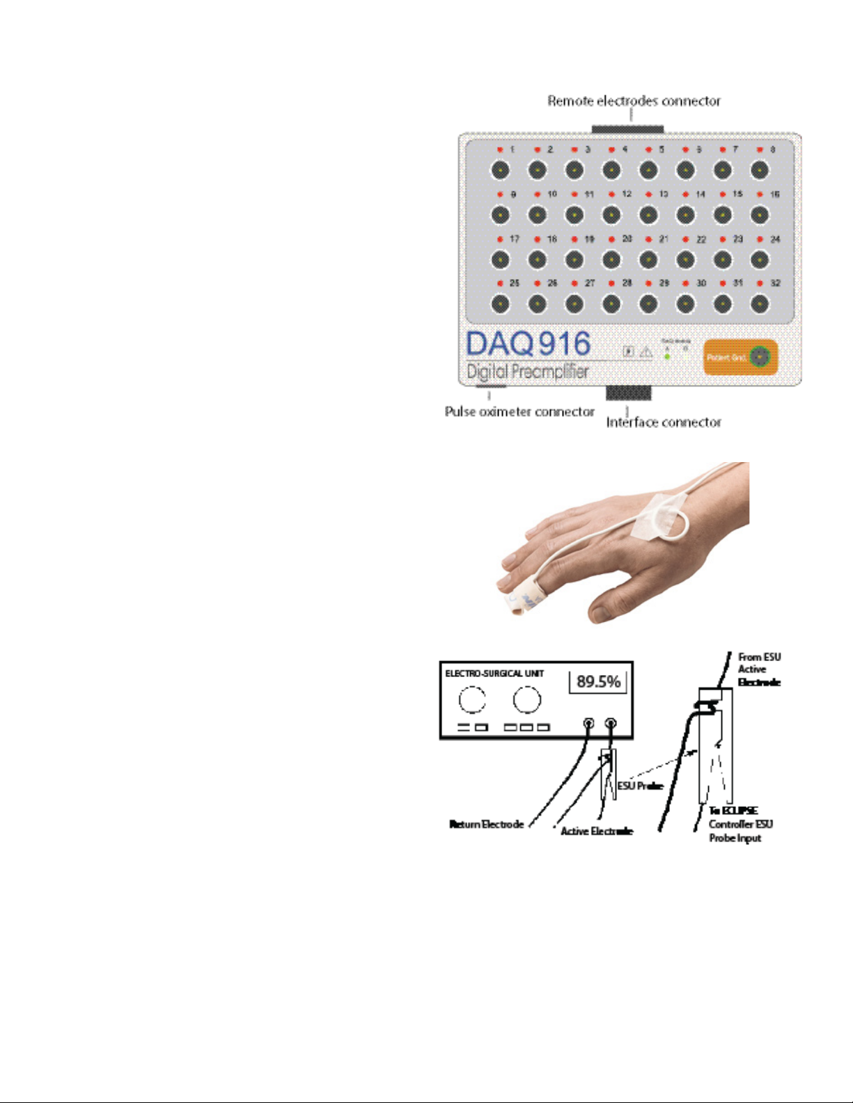
Digital Preamplier Module
The DAQ916 Digital Preamplier Module (DPM) provides signal
detection, amplication, montage selection, A/D conversion, antialiasing ltering, and digital signal preprocessing. Isolated digital data is
routed to the controller, via a 20ft cable, for further processing. The DPM
has inputs for remote electrodes and a pulse oximeter.
Two DPM’s may be used at dierent patient locations to provide up
to 32 recording channels. The DPM’s are labeled “A” and “B”. An LED
will illuminate to indicate the DPM in use. DPM “A” and “B” electrodes
are used as inputs to dene channels and traces. DPM “A” is used for
channels 1 – 16, DPM ‘B” is used for channels 17 – 32.
Patient electrode leads are connected to the DPM input pins in
accordance with the requirements of the specic test. Software
controlled electrode switching allows any of thirty-two (32) inputs to be
congured to form up to 16 channels. When two DPM’s are used, a total
of 64 inputs are available for up to 32 channels. Each input pin has an
LED which will be illuminated when that pin (electrode) is used in the
current recording.
Note: A patient ground electrode must be used on each DPM if two
DPM’s are used in a test.
Pulse Oximeter
The DPM accepts input from one disposable pulse oximeter nger or
toe sensors. If two DPM’s are used, an additional pulse oximeter input
is available. When the pulse oximeters are used, oxygen saturation
information is automatically measured and displayed. Oxygen
saturation can be helpful to monitor for low blood ow in extremities
due to eects of patient positioning.
Note: The use of the Pulse Oximeter sensor with the NIM-Eclipse™ E4
System is not approved in Brazil or Canada.
Electro-Surgery Unit mute probe
The MDP201/945MDP201 Electro-Surgery Unit (ESU) mute probe
senses ESU activity and will automatically mute the EMG speaker audio,
preventing unwanted interference.
Clamp the ESU around only one output wire of the electrocautery
and as close as possible to the interference generating device’s case.
In some cases it may be necessary to loop the ESU wire around the
probe twice. This technique will improve artifact detection. Connect
the MDP201/945MDP201 cable connector to the controller rear panel
connector labeled ESU Probe.
When both monopolar and bipolar electrosurgery units are used, and
are located near each other, the mute probe can be connected to both
as follows: Separate the bipolar ESU leads suciently and clamp the
mute probe around one lead only close to the ESU enclosure. Open
the mute probe clamp and place the monopolar ESU lead as described
above.
Internal ESU detection software is available for use when you do
not have access to the ESU mute probe. To access the internal ESU
detection, open the System settings within any of the protocols to
toggle the ESU detection.
NIM-ECLIPSE™ E4 NS2-3
Page 13
Setting up Hardware
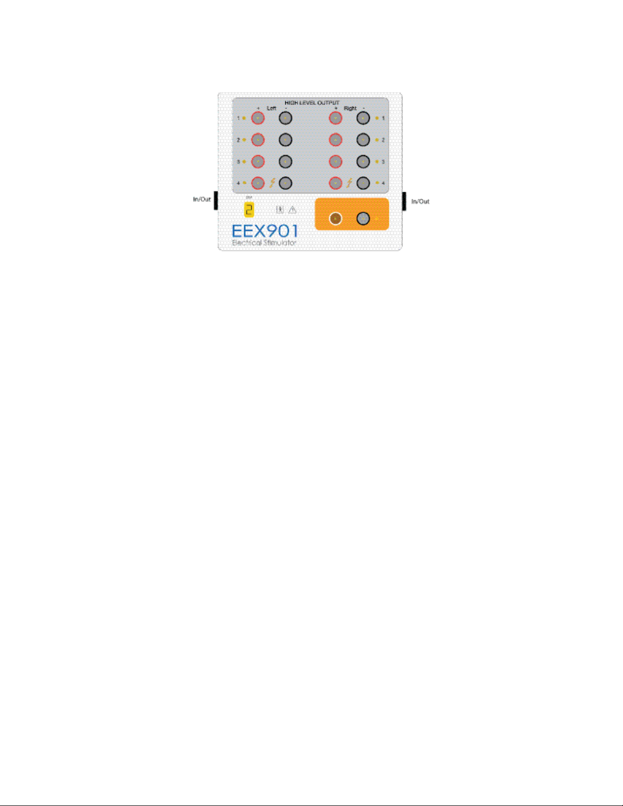
Electrical Stimulator Module
The system’s electrical stimulator module provides stimulation suitable for peripheral, direct nerve, cortical and slow or fast charge transcranial
electrical motor evoked potentials (MEP). A wide variety of triggering modes and pulse outputs are available.
The electrical stimulator is located in the controller. Stimulator outputs are then routed to site selectors located in the EEX901/945EEX901
stimulator extender.
The System accepts up to two EEX901/945EEX901 electrical stimulator extenders, designated ESM1 and ESM2. A numeric indicator displays the
ESM number. Using two EEX901/945EEX901 extenders, up to 16 high level outputs are available. ESM1 interfaces to the controller stimulator via
a 20 ft cable connected to the ESM 1 Input connector. A second extender (ESM2) can be connected via an 8 ft cable from ESM1 output to the
ESM2 input connector.
Connect the cable to either Input/Output end of the EEX901/945EEX901.
The stimulators are electrically isolated from the patient and the outputs are protected by both hardware and software fault detectors to insure
patient safety. Patient current is displayed for both constant current and constant voltage stimulation modes. The stimulator extenders are small
and lightweight and can be placed at the patient location.
The EEX901/945EEX901 provides eight independent high level outputs, paired as left and right, for peripheral nerve stimulation and a low-level
output for direct nerve applications.
Note: Up to 16 high level and 2 low level outputs are available if two EEX901/945EEX901 Stimulator Extenders are used.
The positive (anode) is connected to the red terminal of the site, and the negative (cathode) to the black terminal. EEX901/945EEX901 provides
high level outputs to a maximum of 100mA or 400V and low level outputs to 4mA/4V. Stimulus pulse duration is adjustable for the Low and High
level outputs, respectively. Stimulus rates can be adjusted for all stimuli.
A special MEP stimulation output mode is available using site 4. Output pulses may be either single train or double train.
Stimulator self-test
Left, Right and Low output stimulators are independent of one another and are veried for proper operation by comprehensive self-tests prior to
starting a test or if a stimulator error was detected. If, for some reason, a stimulator fails the self-test procedure the following message appears:
• Please contact Customer Service! Self-test indicates a *** Left *** output failure. If your application allows, you may continue temporarily by
modifying the test output from the Stimulator Output Denition.
Note: The Title Bar of this message includes a specic code relating to the failure. Please make note of this when contacting technical support.
If the result indicates that one output has failed you may have the option to temporality recongure your test protocol and complete the
monitoring procedure. To do so, press OK to continue and change all Stimulus Name references from the failed side to operational side, for
example, from Left 1 to Right 3. Save the Test Protocol with a new name to dierentiate it from the original. The system will then check your
protocol to insure that all Stimulus Names have been changed as described above and, if not, display an error message indicating those Names
requiring a changed stimulus output site.
Stimulator error messages
The stimulators communicate with the main console using a digital serial link. If communications are interrupted, the following error message
will appear:
• Electrical Stimulator Extender Module not found. Check Connections or replace module.
In most cases this error is caused by a faulty connection at the stimulator or console or an electrical disturbance. Check the connections or
replace the stimulator module or cable. If the problem persists, contact Medtronic.
The Electrical Stimulators provide built-in safety mechanisms to insure patient safety. The following error message will appear when the
stimulator detects an internal or external fault:
• Electrical Stimulator Module Error.
NIM-ECLIPSE™ E4 NS
2-4
Page 14

Setting up Hardware
The error message will be displayed for three possible reasons:
• The stimulus settings exceed the built-in safety limits. - Change the stimulus parameters to reduce the output energy. For example, reduce
Stimulus Intensity, Pulse Duration or Stimulus Rate. If train stimulation is used, reduce the Train Count.
• Check for high stimulator electrode impedance. - Reapply or change the electrodes if necessary.
• The stimulator module or stimulator cable is faulty. - Replace the defective component and retry.
Audio stimulators
The System can produce various auditory stimuli to either intraoperative ear insert. Auditory stimulation may be tone bursts, over a wide range
of frequencies and envelopes, or square wave clicks. The stimulus intensity foam ear insert can be varied. Broadband uniform masking noise is
also available.
Visual stimulators
High intensity LED goggles provide visual stimulation. The applied stimulation may be unilateral, or bilateral, with relative intensity level control.
External trigger outputs
The System provides two external trigger outputs which can be used to trigger an external stimulator. The output trigger is a positive true, 100µs
wide, TTL compatible pulse derived from BNC connectors located on the Main Unit connector slots.
Vital signs monitor
The system can be connected to an external Vital Signs Monitor (VSM) to display certain measurements along with the neurological data. Use
this information to correlate changes in the neurological data with ongoing vital signs. The VSM communicates with the System via the serial
port. Connect the VSM to the Serial port of the desktop, or to the serial port or serial port adapter of portable computer. A list of supported vital
signs monitors is provided in the Secondary window settings section.
Microscope view or video camera input
The operator may display the surgeon’s microscope view or video from a camera on the screen along with the monitored data. Connect video to
the USB video adapter. Plug the USB plug into any available USB connector of the computer.
NIM-Eclipse™ System computer
The NIM-Eclipse™ System is supplied with either a desktop or laptop computer with installed software. The computer provides user interface,
data display, communications and output functions. The computer also interfaces with external devices, such as printers, LAN or remote
monitoring features. The computer is supplied with all necessary software applications preloaded.
Consult the supplied computer’s hardware manual (included with the system) for the exact computer specications.
Power Controller Unit
The Power Controller Unit provides complete line isolation and surge suppression for protection of sensitive system components. Each Power
Controller Unit provides electrical outlets congured to connect with the power cords provided with the NIM-Eclipse™ System components. The
Power Controller Unit is used ONLY with the NIM-Eclipse™ System where the system uses the Desktop small form factor computer unit.
Connecting the system components
The NIM-Eclipse™ System is a highly sensitive instrument capable of detecting microvolt level physiological activity. Every precaution is taken
in the instrument design to reduce extraneous and unwanted interference due to electrical noise (motors, uorescent lights, etc.) which may
compromise data acquisition. This interference is characterized by an excessive line frequency signal present in the Live or Current Sweep display
modes. Selection of a suitable installation site will minimize or eliminate this eect.
The back panel of the Main Console has a power ON/OFF switch. This switch may be kept in the ON position, and the entire system activated
from the Power Controller Unit On/O switch.
Note: Power must be applied to the System controller prior to applying power to the computer. If power to the controller is interrupted, be sure
to sequence power on as described.
Note: In the event the computer does not respond to keystrokes or mouse movements, press and hold the power button for 10 to 20 seconds to
restart the system.
NIM-ECLIPSE™ E4 NS2-5
Page 15

Setting up Hardware
Connection guide
The NIM-Eclipse™ System has connectors on the rear panel to interface to the PIM, ESU mute probe, and other devices. Connect the patient
related peripherals as required for your application as shown in the diagram below. An optional mouse may be connected to the NIM-Eclipse™
System via the computer USB ports. To connect an optional printer to a laptop NIM-Eclipse™ System, a wireless connection such as Bluetooth™*
or WiFi™* must be used. If a desktop system is used, the optional printer may be connected via USB.
If a desktop computer is used instead of a notebook computer as shown, plug the Power Controller Unit into the Hospital Grade Receptacle, then
plug the NIM-Eclipse™ System components; including printer, monitor, and other similar connected accessories; into the Power Controller Unit.
Only the Power Controller Unit should be connected to a Hospital Grade Receptacle as it provides electrical isolation to the equipment. Do not
bypass the Power Controller Unit by plugging these accessories directly into a wall outlet.
NS System Connection Diagram
NIM-ECLIPSE™ E4 NS
2-6
Page 16

Setting up Hardware
Powering on the system
Once all connections have been made:
1. Plug the NIM-Eclipse™ System controller into a hospital grade receptacle or the Power Controller Unit that has been plugged into a hospital
grade receptacle. Ensure the NIM-Eclipse™ System is positioned so it can be easily disconnected from the hospital grade receptacle, if
necessary.
Note: If using a desktop computer with Power Controller Unit, turn the Power Controller Unit on by placing the switch in the I position.
2. Press the NIM-Eclipse™ System controller rear panel power switch button.
3. After ve seconds, press the power button on the computer.
NIM-ECLIPSE™ E4 NS2-7
Page 17

Section 3: Quick Start and Stop
In this section, you will be able to:
1. Use the NIM-Eclipse™ System on a basic level.
2. Stop the NIM-Eclipse™ System.
Page 18

Quick Start and Stop
Quick start procedure
The following are instructions to quickly get up and running with the NIM-Eclipse™ System. These instructions are very general and represent
only the basics of operating the system. We encourage you to read the manual thoroughly to make full use of the exibility and power of the
NIM-Eclipse™ System.
To get started with the NIM-Eclipse™ System:
1. Connect the system as described in the Setting Up Hardware section.
2. Power on the Controller.
3. Power on the Computer.
4. Conrm the Operator name on the NIM-Eclipse™ System splash screen, then click [NS].
5. Click [Run Test]. Select the appropriate protocol from the protocol list and click [Run], or, double-click on the selected protocol.
Note: Default protocols are provided as examples of the systems capabilities. Do not use default protocols without prior conrmation that
they are applicable for the intended procedure.
6. In the Select Patient window, select Existing Patient, New Patient or Unnamed based on case needs, then click [OK].
7. Connect appropriate disposables, such as electrodes, to Digital Preamplier & Stimulator modules.
8. Click the Impedances icon.
9. Verify impedances and electrode placement on the patient.
10. Click [Close] at the bottom of the Impedances window.
11. As necessary, use the icons on the right side of the screen to modify settings while monitoring.
12. Press F1 to open system help.
13. Click [Save] to save the Protocol.
Quick stop procedure
The following are instructions to quickly stop and shut down the NIM-Eclipse™ System.
1. Click the Stop All icon on the NIM-Eclipse™ System screen or F2 on the keyboard to stop recording and stimulation for all started modalities.
2. Click the System Menu icon on screen and select Close to close the protocol.
3. Click the System Menu icon on screen and select Exit to close the system.
4. Click the Windows™* Start menu and select Shut Down to turn o the computer.
5. Turn o the power of the NIM-Eclipse™ System controller.
6. Turn o the NIM-Eclipse™ System Power Controller Unit (desktop version only).
3-1 NIM-Eclipse™ E4 NS
Page 19

Section 4: Creating and Modifying Protocols
In this section, you will be able to:
1. Understand NIM-Eclipse™ System screens
2. Use the Patient Information Panel
3. Use the System Settings Panel
4. Understand Electrodes and Channels
5. Create a Protocol
6. Modify a Protocol
7. Use the Modalities Settings Panel
8. Use the Stimulus Settings Panel
9. Use the Secondary Windows™* Settings Panel
10. Use Diagnostics
11. Use the Speaker Settings Panel
12. Use the Comments Settings Panel
Page 20

Creating and Modifying Protocols
NIM-Eclipse™ System Run/Modify Test selection screen
The NIM-Eclipse™ System Run/Modify Test Selection screen contains protocol tabs and Medtronic and user-dened protocol lists.
1. System Menu: Use this menu to access System Info, Help, User’s
Manual, Support, and to Exit system.
2. Protocol tabs: Displays the protocol list by protocol type.
3. Refresh (or F5 key): Click to refresh the protocol list.
4. Minimize: Click to minimize window.
5. Maximize: Click to maximize window.
6. Close: Click to close the application.
7. System Settings: Allows users to change the general settings for
the overall system.
8. Show/Hide settings panel: Shows/Hides settings and chat.
9. Resize window: Drag to resize the window display.
10. Modify Protocol: Allows users to modify protocols from a list of
saved protocols.
11. New Protocol: Allows users to create/save new protocols.
12. Remote View: Allows users to enable remote networking.
13. Review Test: Shows list of saved procedures available for review.
14. Resume Test: Allows users to resume a test/procedure.
15. Run Test: Allows users to select/run protocols from a list of saved
protocols.
16. Run/Modify: Click to run/modify the selected protocol.
17. USERS: Toggle between Medtronic and user-dened protocols.
18. Protocol list: Displays the list of saved protocols, their related
modalities, the date and time when the protocol was last saved,
and any notes. Select a protocol by clicking on it. A quick doubleclick will select and run the protocol.
4-1 NIM-ECLIPSE™ E4 NS
Page 21

Creating and Modifying Protocols
NIM-Eclipse™ System Resume/Review Test selection screen
The NIM-Eclipse™ System Resume Test screen displays a list of recently run tests. The NIM-Eclipse™ System Review Test screen displays the patient
test inside the selected folder. You can review patient tests recorded with the NIM-Eclipse™ NS or NIM-Eclipse™ SD Systems.
Right-click the column headers to show/hide columns.
1. System Menu: Use this menu to access System Info, Help, User’s
Manual, Support, and to Exit system.
2. Folder path and Folder icon: Displays the address of the selected
test. Click the icon to open the browser to select a test.
3. Refresh (or F5 key): Click to refresh the screen.
4. Minimize: Click to minimize window.
5. Maximize: Click to maximize window.
6. Close: Click to close the application.
7. Patient and Case Information: Displays a series of panels that
enables users to complete case information including Personal,
Case Sta, Case Info, Case Details and Monitored Modalities, Alerts,
Alarms.
8. System Settings: Allows users to change the general settings for
the overall system.
9. Show/Hide settings panel: Shows/Hides settings and chat.
10. Resize window: Drag to resize the window display.
11. Modify Protocol: Allows users to modify protocols from a list of
saved protocols.
12. New Protocol: Allows users to create/save new protocols.
13. Remote View: Allows users to enable remote networking.
14. Review Test: Shows list of saved procedures available for review.
15. Resume Test: Allows users to resume a test/procedure.
16. Run Test: Allows users to select/run protocols from a list of saved
protocols.
17. Resume/Review: Click to resume/review the selected test.
18. Patient list: Displays the list of patients, the date and time when
the protocol was last saved. Right-click a test and select from
the available options. Right-click the header line to select which
columns are visible.
4-2NIM-ECLIPSE™ E4 NS
Page 22

Creating and Modifying Protocols
Create a protocol
The New Protocol feature enables users to create and save new protocols.
1. Click [New Protocol] on the Main screen.
2. Use the Add Modality (plus sign) on the modality settings panel to add the desired modalities.
3. Use Modalities Settings to congure parameters for the modalities to be included in the protocol. Refer to the Modality Settings topic for
more information.
4. Click System Menu > Save As to save the protocol.
5. In the Save As window, navigate to the user sub-folder location where the protocol will be saved.
6. Name the Protocol, then click Save.
Modify a protocol
The Modify Protocol feature enables users to modify and save existing protocols. The window is divided into Protocol Name, Modalities, Date and
Time, and Notes columns. To modify a protocol, click [Modify Protocol] on the Main screen.
• Users: These folders are used to store Medtronic preset protocols and user created protocols. Right-click on a folder to add, rename, or
remove the folder.
• Protocol Tabs: Protocol tabs organize available protocols into categories. Right-click on a tab to add a new category or rename or remove
existing categories.
• Protocol List: The Protocol List displays all standard Medtronic (read only) and user dened test protocols. Test protocols are further
subdivided by the protocol tabs at the top of the screen. Right-click over a protocol name and select from the displayed menu one of the
available functions. Multiple protocols can be selected for simultaneous Export and Delete. Right-click the header line to import protocols.
• Read only: Factory Preset protocols are read only, but may be modied and saved with a new name.
• User dened: User dened tests are created either directly or indirectly by modifying and renaming a factory preset test.
To modify a protocol:
1. On the Main screen, locate the appropriate protocol in either the Medtronic or User folders and within the protocol tabs.
2. Highlight the desired protocol and click [Modify], or double click the desired test protocol.
3. Use Modalities Settings to congure parameters for the modalities to be included in the protocol. Refer to the Modality Settings topic for
more information.
4. Click System Menu > Save As to save the protocol.
5. In the Save As window, navigate to the user sub-folder location where the protocol will be saved.
6. Name the Protocol, then click Save.
Run a test
The Run Test screen contains a list of factory preset and user-dened test protocols. The window is divided into Protocol Name, Modalities, Date
and Time, and Notes columns. To run a test, click [Run Test] on the Main screen and do the following:
1. Locate the appropriate protocol in either the Medtronic or User folders and within the protocol tabs.
2. Highlight the desired protocol and click [Run], or double click the desired test protocol.
3. In the Select Patient window, choose an existing patient or enter the name and ID number of a new patient.
• Select an existing patient’s information to add to the Case. When selecting an existing patient, the patient’s information populates in the
Patient and Case info Panel on the monitoring screen.
• Provide new patient information. In the Select Patient window, type the patient’s rst name, last name, and ID number. Patient
information for this new patient can be modied in the Patient Information Panel on the monitoring screen.
• Select an Unnamed Patient. When selecting an unnamed patient in the Select patient window, patient information can be modied in
the Patient Information Panel on the monitoring screen.
4. Click [Ok].
Start/Stop, Stop All, and Pause/Resume Stimulation
• Press the Start/Stop button on the modality window title bar to start/stop recording and stimulation.
• Press the Stop All icon to stop recording and stimulation for all started modalities.
• Press the Pause/Resume icon to pause/resume repetitive or single sequence stimulation for all started modalities. Delivers the next stimulus
when non-repetitive stimulation.
4-3 NIM-ECLIPSE™ E4 NS
Page 23

Creating and Modifying Protocols
Run test functional keys
Use the following functional keys on the keyboard to perform NIM-Eclipse™ System functions while running a test.
Key Run Test
F1 Help
F2 Stop All
F3 Pause/Resume stimulation, or next stimulus
F4 Impedance
F5 N/A
F6 N/A
F7 Next average
F8 Install baseline
F9 Save screen
F10 Print screen
F11 Speaker On/O
when non-repetitive stimulation. Use Shift+F3 in
simulation mode to simulate measured current.
Resume a test
From the Main screen, users can resume test from the last saved point. The user can resume a test as long as the period of time between starting
and resuming a test doesn’t exceed 7 days. The resume test screen contains the following sections:
• Patient Name: Field contains the patient name.
• ID: Field lists the ID number associated with the patient.
• Protocol: Field lists the name of the Protocol.
• Date and Time: Field lists the date and time the protocol was created.
• Folder: Field contains the folder name for the patient or patient data. Right-click over the header line of the list to show/hide the folder.
To resume a test:
1. Click [Resume Test] on the NIM-Eclipse™ System Main screen.
2. Select the patient test to be resumed.
3. Click Resume.
4. Click Yes to reset all stimulus Intensities to zero, or No to retain stimulus intensity settings.
Resume a test after accidental power loss
The following are instructions to resume a test after accidental power loss:
1. Turn on the computer, if it is not rebooted automatically.
2. Launch the NIM-Eclipse™ System application.
3. Follow the Resume a test procedure above to continue.
Note: Select Yes to reset all stimulus intensities to zero during Resume a test.
4-4NIM-ECLIPSE™ E4 NS
Page 24

Creating and Modifying Protocols
Patient Information
The Patient Information panel enables users to enter data about the case. Access the Patient Information panel from the NIM-Eclipse™ System
Resume or Review screen by clicking the Patient Information icon.
There are several sections in the Patient Information Tab. Each of these sections contains a series of text entry elds and lists for data entry.
Personal
The Personal section contains information elds specic to the patient
such as vital statistics, patient’s address, and notes.
Case Sta
The Case Sta section contains information elds used to
list the individuals involved in the case such as the surgeons,
anesthesiologists, technicians, and hospital.
4-5 NIM-ECLIPSE™ E4 NS
Page 25

Creating and Modifying Protocols
Case Details
The Case Details section contains elds for history, pre- and postoperative neuro decit.
Case Info
The Case Info section contains elds used to list information about the
case such as the diagnosis, procedure, muscle sites, anesthesia, and
surgery start and end time. The system automatically lls Monitoring
Start and End when the user starts/stops a modality.
4-6NIM-ECLIPSE™ E4 NS
Page 26

Creating and Modifying Protocols
Monitored Modalities, Alerts, Alarms
When the user starts a modality, the system automatically marks it as a monitored one. The system shows Numbers of Alerts and Alarms per
modality. Click the Details icon (3 dots) to review or modify these events.
4-7 NIM-ECLIPSE™ E4 NS
Page 27

Create a Patient Prole
1. Click [Review Test].
2. Click the Patient and Case Information icon.
3. Click + in the Patient Information panel.
4. In the New Patient window, type the patient’s name and ID number in the elds.
5. Press [OK].
Modify a Patient Prole
1. Click [Review Test].
2. Select the patient from the list.
3. Click the Patient and Case Information icon.
4. Modify patient information in the Patient Information panel.
Delete a Patient Prole
1. Click [Review Test].
2. Select the patient from the list.
3. Click the Patient and Case Information icon.
4. Click [] in the Patient Information panel.
5. In the Delete Patient Data window, click [OK] to delete the selected patient’s data.
Alternatively, to delete a patient prole:
1. In the review test screen, right-click the patient test and select Delete.
2. In the Delete Patient Data window, click [OK] to delete the selected patient’s data.
Creating and Modifying Protocols
Edit Lists
Users can edit preset items in the Patient Information panel by using the List Editor feature. Refer to the “Report Generator” topic for a
description of how to edit lists.
To open the list editor:
1. Click the Patient and Case Information icon.
2. Click either Case Sta or Case Info to reveal [Edit List].
3. Click [Edit Lists].
4-8NIM-ECLIPSE™ E4 NS
Page 28

Creating and Modifying Protocols
System Settings
The System Settings panel controls the look and feel of the NIM-Eclipse™ System.
On the panel, the user can congure General settings as described below.
General tab
• The Language setting enables users to select the language that the system
displays.
• The Units settings enable users to select what units the system uses.
• The Amplitude Decrease warning setting enables the user to enter the
percentage drop of the response amplitude when the system displays a
warning. A zero value disables the warning.
• The Latency Increase warning setting enables the user to enter the increase
in a percentage when the system displays a warning. A zero value disables
the warning. The system displays a MEP/H-Reex latency warning only if the
peak-to-peak amplitude is above or equal to the Threshold level.
• ESU software detection enables the software to detect the ESU, mute the
audio, and stop the stimulation. To work reliably, connect the recording
electrodes for all EMG channels to the patient.
• The ESU software detection algorithm uses the Detection level setting. Adjust
the level to work appropriately with your ESU devices.
• The Type setting contains the Butterworth, Chebyshev and Bessel lter types.
• The Slope LFF settings set the Low Frequency Filter (LFF) default lter slope
at either 6 dB/octave, or 12 dB/octave. The 12 dB/octave setting will provide a
steeper slope.
• The Slope HFF settings set the High Frequency Filter (HFF) default lter slope.
Select 12 dB/octave or 24 dB/octave. The 24 dB/octave setting will provide a
steeper slope.
• The Notch Frequency setting enables users to select either 50 or 60 Hz for the
notch frequency.
• When the user checks [Create research le], the system creates/updates the
le for the case every time the user changes a eld used in the research le
while in the main screen, or when the user closes run/review. The system does
not create the le for tests saved with 4.3.423 or earlier versions. The system
uses the patient encrypted name and data folder name for the le name.
Also, the system creates two other les: the “Res_Header.cvs” le with column
headers for the research data les and the “Res_Lists.cvs” le with the list
items used for the elds in the research le. The [Folder Name] selects where
to create the le. [Combine all research les] creates the “Res_Data.cvs” le.
If the user checks [Include header in the combined le], the system puts the
header line in that le.
• When the user checks [Enable export of EP current sweeps], the system
exports individual EP sweeps for a modality while [Current Sweep (Live)] is
checked. The system places les with exported data in the test data folder.
• The Show on Status Bar list enables users to select what displays on the status
bar.
• The Thumbnail Width slider controls the width of the trace and other
thumbnails when minimized.
• Pen width controls the width of the displayed traces.
4-9 NIM-ECLIPSE™ E4 NS
Page 29

Colors tab
• The Color Mode setting enables users to select Black, White, Custom, and
Printer color modes. Each color mode provides a default palette of colors that
the system uses to display information.
• The Set Default setting resets all changes made to the color palette.
• The colors for the selected color mode are organized in two groups; Common
Colors group and EEG/EMG Channels group.
• The system assigns the Selected Color to a color setting when the user clicks
on that setting. Select a color from the list, or press [Advanced] to select a
color from the palette. Click anywhere in the screen to close the Selected
Color list.
• If the user checks [Display Captured] and there are captured traces, the
system uses channel colors for the captured traces and the EMG Response
color for the raw traces.
Creating and Modifying Protocols
4-10NIM-ECLIPSE™ E4 NS
Page 30
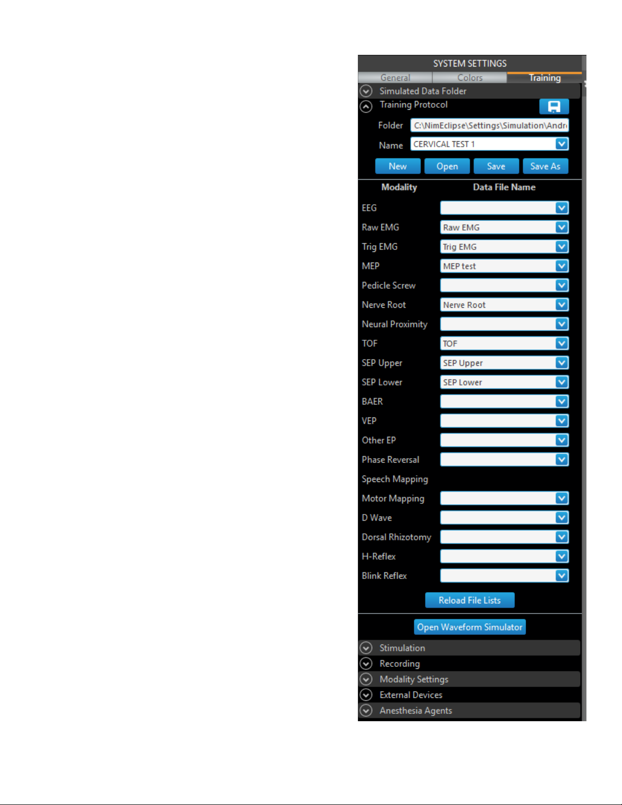
Creating and Modifying Protocols
Training tab
• The Training settings enable the system to simulate data for dierent
modalities and situations and display the data while running a test.
• The user can control the Training settings from the same computer which is
running the test, or from a dierent computer. Both programs must create
the same “Simulated Data Folder”.
• The Training tab is always available in the System Settings main screen and
during a run test, modify test, and new protocol in simulation mode. When
in run mode, the only settings available are the Simulated Data Folder and
Anesthesia Agents settings.
• Use the Open Waveform Simulator setting to generate data for the
modalities. Click on any Waveform or Ampl Change window to change its
shape.
4-11 NIM-ECLIPSE™ E4 NS
Page 31

Creating and Modifying Protocols
Electrodes and Channels
Use the Electrodes and Channels window to edit electrode names and dene channels for both recording and stimulation. The Electrode and
Channels window contains the sections for DAQ Ports A & B, Sets, DAQ A & B Channels, and High and Low-level stimulation output for ESM 1 & 2.
• Trash Can: Allows the user to delete an entire DAQ channel in the Electrodes and Channels window, by clicking on the channel “Type” (next
to the channel to be deleted) and dragging it to the Trash Bin. When a DAQ channel is deleted it will be removed from all modalities using it.
DAQ Channels can be deleted at any time when create or modify protocol. When running a test, a DAQ channel can be deleted only before
any modality using it has started.
• [Save]: Saves the electrode names in a le for future use in other protocols.
• [Load]: Loads all electrode names from a le. The button appears only when there are no dened electrode names.
• [Recording Boxes]: Displays the Recording Boxes window.
• [Stimulating Boxes]: Displays the Stimulating Boxes window.
• [Cancel]: Close the Electrodes and Channels window without saving data.
• [Apply]: Apply dened electrodes and channels to the current protocol.
4-12NIM-ECLIPSE™ E4 NS
Page 32

Creating and Modifying Protocols
Naming electrodes
When creating a new test, the electrode name elds are blank. If an existing test is being edited, the electrode names for that test appear. Click
on the name eld for an electrode to edit it. Press [Tab] to move between electrode names. Electrode names may be up to eight characters long.
You only need to name those electrodes that will be used in the test.
Assigning channels
Channels are used to pair signals from the electrodes. The DAQ Channels section is used to assign electrode names to the positive (Reference
Input) and negative (Active Input) amplier inputs of a channel, forming a dierential pair. These assignments are performed for each set and
dene the channels used in that set. An electrode may be assigned to more than one channel.
You may assign electrodes to the input pins of as many available channels as needed, and must assign inputs for all channels used in the
protocol.
To assign electrodes to channels:
1. Click the appropriate modality tab at the top of the screen, then click the appropriate Set where the channel will be assigned.
2. Click the channel where the electrodes will be assigned, then click the electrodes to assign them to the selected channel.
3. Select Sel to assign the channel to either the Left side or Right side. When dual modality is selected the assignment will be for the left or
right stimulus. Use the Name text box to rename the channel, if necessary.
4-13 NIM-ECLIPSE™ E4 NS
Page 33

Creating and Modifying Protocols
Sets
When there are not enough channels, sets may be used to provide additional channels. To create sets, redene the DAQ channel electrodes in
dierent sets. Modalities having channels in dierent sets cannot be run simultaneously if they have overlapping channels. All channels for a
modality must be in the same set.
An asterisk indicates the set that contains the channels for the selected modality..
Example: SEP Upper tab is highlighted and Set 1 is selected. The asterisk indicates that the SEP Upper is located in Set 1.
Stimulating Boxes
The settings in this group determine the Stimulator Extender Module used (either ESM 1 or ESM 2) and the stimulator output site for the selected
modality. The High Level Output sites on EEX901/945EEX901 are grouped by Left and Right side. Each side has four outputs labeled 1, 2, 3 and 4.
The Site Output setting selects the stimulator output site. The Outputs are Left 1, Left 2, Left 3 and Left 4 and Right 1, Right 2, Right 3 and Right
4. A Stimulation Site is dened by selection of module (ESM 1 or ESM 2) and Output. Site selection is aected by the Stimulation Mode. In the
Unilateral Mode only Site 1 is available. In Bilateral Mode both Sites 1 and 2 are available. For example, if bilateral stimulation were used, the
Output sites could be set to Left 1 and Right 1.
To access the Stimulus Boxes window, click [Stimulus Boxes] on the Electrodes and Channels window.
Modalities
When modalities are added, correct values are assigned to their parameters. Several modalities described below have special features.
EEG
The EEG modality displays the spontaneous electrical activity of the brain presented in a scrolling display. Fast Fourier Transform (FFT)
techniques can also be performed to provide alternative formats to interpret EEG data. The FFT options available are compressed, density, and
color density array.
Raw EMG
The Raw EMG modality displays high frequency spontaneous activity recorded from dierent muscles. If Captured Responses is enabled,
responses will be captured when the signal exceeds the response amplitude and will be displayed above the trace in the trace window. The
captured response will remain displayed until the signal again exceeds the threshold. If EMG Audio Tone is enabled for Raw EMG, a beep tone
will be heard whenever the signal exceeds the threshold. Select [Save] to manually save the Raw EMG for 30 seconds before and after the click.
Triggered EMG
If Captured Responses is enabled, triggered responses will be captured when they exceed the threshold amplitude and will be displayed above
the trace in trace window. The captured response will remain displayed until another triggered response exceeds the threshold. If EMG Audio
Tone is enabled for Triggered EMG, a beep tone will be heard whenever the triggered response exceeds the threshold. Select [Freeze] to stop
updating the window while the system still collects data.
4-14NIM-ECLIPSE™ E4 NS
Page 34

Creating and Modifying Protocols
MEP
The MEP test is designed to quickly assess the integrity of the motor pathways by applying
predened, constant voltage stimulus to the motor cortex and recroding subsequent compound
muscle action potentials from allocated muscles. When a MEP stimulus is used for safety reasons
an additional “Enable” button will be displayed next to “Start” on trace and stack window title bar.
Click “Enable” to enable the “Start” button.
Pedicle Screw
The Pedicle Screw Integrity Test is designed to quickly and automatically verify proper
positioning of pedicle screws during spinal xation procedures. To select the pedicle levels that
are needed, access the stimulus parameters for the pedicle screw test and deselect the Show
selected pedicle levels only option.
To start an automated test, click on a pedicle level button in Stimulus settings panel or in
Spine window. The test begins by stimulating at the Start Intensity. For each stimulus the EMG
response is measured within the Response criteria and a response either passes or fails based on
the Pass/Fail criteria. If a response is found at a particular intensity, repeat tests are performed
to ensure accuracy. Responses are marked with comments indicating the level tested, stimulus
intensity, Pass/Fail or No Decision. For a passed or failed test, the system enters the comment
with the channel that has the response. The Pedicle Screw Integrity test provides the user with
voice or tone-status indicators and ability to stop the test after the rst response is found or to
continue the test until the End Intensity is reached. Use two dierent stimuli for dierent pedicle
levels.
Manually perform the test by clicking the Start button on the Trace window; adjust the stimulus
intensity. When the manual test is complete, click the pedicle level button to generate a
comment for the result.
Enabling the pedicle screw audio will prompt the NIM-Eclipse™ System to silence the EMG audio
during the pedicle screw testing phase. Once the pedicle screw testing is complete, the system
automatically adjusts the EMG audio.
Pedicle Tract
The Pedicle Tract is an additional test that the user can perform in the Pedicle Tract modality. The user can switch between Screw and Tract
testing by selecting the button next to the Start button on the title bar of the Trace window. The user can perform the Pedicle Tract test in an
automated or manual mode in a similar way to the Pedicle Screw test. The system generates comments when the user checks the Pedicle Tract
checkbox on the Comments Settings dialog.
To run the Pedicle Tract test in the automated mode:
• Click a pedicle level to start auto mode.
• Click the same pedicle level while started will stop the modality.
• Clicking another pedicle level while started will cancel the testing for the rst level and will initiate testing for the new level.
• The system sets the stimulus intensity to “Auto Intensity Start” value.
• When the probe touches a hole, the system initiates the test, and the system changes intensity following the logic of the Neural proximity
modality.
• While initiated, the program checks for response using the same logic as the pedicle screw test.
• If the system nds a response, the program saves the stimulus intensity for the response.
• If the system nds another response at a lower intensity, that intensity replaces the previously saved intensity.
• The test ends when the the user removes the probe from the patient.
• When the test ends, if the system nds a response, the system bases the comment on the response intensity. If the system does not nd a
response, the system bases the text on the maximum intensity used in the testing.
To run the Pedicle Tract test in manual mode:
• Click [Start] to start manual mode.
• The system sets the stimulus intensity to the “Auto Intensity Start” value. The user can change the stimulus intensity.
• The system initiates the test when the probe touches a hole.
• While initiated, the program checks for a response using the same logic as pedicle screw test.
• The program saves the stimulus intensity for the response if it nds a response.
4-15 NIM-ECLIPSE™ E4 NS
Page 35

Creating and Modifying Protocols
• If the system nds another response at a lower intensity, the system replaces that intensity with the previously saved intensity.
• The system generates a comment if the user clicks a pedicle level. If the system nds a response, the system bases the comment on the
response intensity. If the system does not nd a response, the system bases the text on the current intensity.
• The hole test ends when the user removes the probe from the patient.
• While the probe is removed, the results will be kept and a comment will be generated by clicking on a pedicle level in the same way as
clicking while the probe was touching the hole.
• If the user touches the patient with the probe, the system continues the pedicle tract test in the same way as if the user clicks [Start].
Nerve Root
The Nerve Root test relies on direct stimulation of the nerve root and it is used to locate and quantify the health of a nerve root. The test is
performed in a similar way to the Pedicle screw test. Results of the Nerve Root test are saved and can be used as a reference when performing
the Screw Integrity Test.
Complete automated or manual testing in the same way as pedicle screw testing.
Neural Proximity
The Neural Proximity mode automatically changes stimulation intensity directed to an electried instrument while searching for an EMG
response. Responses found at lower stimulation intensities indicate the nerve is closer to the instrument site. Audio feedback indicates nerve
proximity. High and low frequency tones indicate a nerve near or more distant to the electried instrument site respectively.
Train of Four (TOF)
Train of Four (TOF) records the compound muscle action potential (CMAP) which is the cumulative electrical activity generated by individual
action potentials of the individual muscle bers. The amplitude of the TOF CMAP response is proportional to the number of muscle units
innervated. Record a baseline TOF response after the patient has been anesthetized and before administration of neuromuscular blocking
agents. It is appropriate to record TOF responses from a muscle in the extremity where EMG activity is being monitored. Position the active
recording electrode on the belly of the muscle and a reference at the muscle tendon.
Examples: For upper extremity monitoring, stimulate at the ulnar nerve and record TOF responses from the adductor pollicus muscle. When
monitoring the lower extremity, stimulate tibial nerve at the ankle and record from the adductor hallucis.
TOF modality has an additional “Calibrate” button displayed next to “Start” on the trace window title bar. When the TOF test is activated by
pressing the “Start” button, the system will generate four stimuli using supramaximal current intensity at 2 Hz stimulation rate. The intensity can
be set by the user using the intensity slider when the “Calibrate” button is pressed.
TOF Stimulation Artifacts
Stimulus artifact may obscure the TOF responses or provide incorrect measurements, especially when the stimulation and recording electrodes
are in close proximity. To reduce the eects of stimulus artifact:
• Prep the skin with abrasive prior to applying stimulation or recording surface electrodes.
• Do not place the proximal stimulation electrode closer than 2, preferably 3, inches from the recording electrode.
• Place the stimulation electrode centers no further than 1 inch apart.
• Use small, 15mm x 20 mm surface area stimulation electrodes.
• Use biphasic stimulation.
SEP Upper and Lower
Upper SEP – This modality is used to access the somatosensory pathways from the upper extremities. Stimulation is usually applied at the wrist
over the ulnar or median nerves, bilaterally. Recording electrodes are placed at various sites along the pathway, ending at the corresponding
sensory portion of the cortex. Averaged responses are recorded and measured for both latency and amplitude changes.
Lower SEP - This modality is used to access the somatosensory pathways from the lower extremities. Stimulation is usually applied at the ankle
over the posterior tibial nerve or at the knee over the peroneal nerve, bilaterally. Recording electrodes are placed at various sites along the
pathway, ending at the corresponding sensory portion of the cortex. Averaged responses are recorded and measured for both latency and
amplitude changes.
BAER
The brainstem auditory evoked potential (BAEP) modality is used to evaluate the functional integrity of the auditory nerve pathway to the
brainstem. Ear inserts are used to provide click or tone stimulation to the auditory nerve. Averaged responses are recorded and measured for
both latency and amplitude changes.
VEP
The visual evoked potential (VEP) evaluates the functionality of the visual pathway from the retina to the occipital cortex. LED goggles are placed
over the eyes and a ash stimulus is delivered to the closed eye. Recording electrodes are placed on the scalp over the occipital portion of the
cortex. The resulting averaged waveform is measured for both latency and amplitude changes.
4-16NIM-ECLIPSE™ E4 NS
Page 36

Creating and Modifying Protocols
Other EP
This modality is used when the desired modality is not available in the predened modalities listed.
Speech Mapping
The Speech Mapping modality is used to nd the speech related areas of the brain. The stimulation is applied for a selected period of time. There
is no recording available for Speech Mapping stimulation.
When starting the Speech Mapping modality, the stimulator becomes active at 0.5mA. Select the delivered current amount. When the stimulator
comes into contact with the tissue it delivers this amount for a selected amount of time (default is 4 seconds). After the selected duration has
elapsed, the delivered current amount will stop and return to 0.5mA. To initiate another stimulation, the stimulator tip must break contact with
the tissue to prime the instrument for the next stimulation. If the Speech Mapping Audio Tones checkbox is enabled, tones will alert the user
when stimulation is initiated by contact with tissue, when stimulation ceases, if the instrument breaks contact with the tissue, or if the selected
time has elapsed.
Motor Mapping
The Motor Mapping modality is used to nd the motor related areas of the brain. Press [Freeze] to stop updating the window while the system
still collects data.
D Wave
The D-Wave modality is used to test the motor pathways of the spinal cord. Transcranial electrical stimulation is applied on the scalp over
the motor cortex. The D-Wave response is recorded from the epidural space of the spinal cord with the use of an epidural catheter electrode.
H-reex
The H-reex modality is used to evaluate the nerve’s ability to conduct between the extremity and spinal cord. Stimulation is delivered at
the level of the extremity and travels along the sensory nerve bers to the level of the spinal cord where it transverses and returns down the
extremity on the motor bers of the nerve. The wave following the initial motor response is called the H-Wave (H-reex).
Phase Reversal
TThe Phase Reversal modality is used to nd the central sulcus of the brain.
Blink-Reex
The Blink-Reex modality is used to monitor some nerves in the head.
Dorsal Rhizotomy
The Dorsal Rhizotomy modality is used to select nerves for Rhizotomy surgical procedure.
Modality Settings
The Modality Settings panel contains all parameters for adding/removing modalities and modifying the recording and displaying settings. The
Modality Settings panel is divided into the following sections; Trace, Stack, Spectral, Numeric, and Markers.
• Modalities can be added at any time while creating a protocol or running a test.
• Modalities can be removed at any time during creation of a protocol.
• When opening a protocol, modalities cannot be removed after any test has started.
To add modalities:
1. Click the Add Modality Button [+] at the top of the Modality Settings panel.
2. Select a modality in the Modality Type eld.
3. Complete the elds that appear in the Modality Settings panel and then click [Add].
Note: The following elds appear on the Modality Settings panel but are not applicable to all modalities.
• Modality Name: Use the Modality Name eld to rename the modality. By default, the type of the modality is listed in the eld followed
by its number of occurrence.
• Stimulus Type: Use the Stimulus Type eld to select the type of stimuli to be used with the selected modality. Depending on the
modality, the types of stimuli available are Electrical, Audio, Goggles, and External Trigger Out. The system lists only the stimulus types
available for each modality.
• Left or Right: Select one or both of these options to assign unilateral or bilateral stimulation.
• Biphasic: Select Biphasic to achieve zero net charge (cancellation of positive and negative charge) stimulation. When Biphasic is
selected, a positive pulse is followed immediately by a negative pulse of equal amplitude and duration.
• Facilitation: Select Facilitation to deliver an additional stimulus to prime the lower motor neuron (LMN), before delivering the MEP
stimulation.
• Use Two Stimuli: Available only for pedicle screw modality. Allows the use of two dierent stimuli for dierent pedicle levels.
• Neural Mode: Only available for the neural proximity modality. The system uses two stimuli when the user selects “Spinal cord and
Nerve”.
• MEP Mode: Only available for MEP modalities. Provides proper default settings for each mode.
• Sweep Length [ms]: Use the Sweep Length eld to select the sweep length in milliseconds.
4-17 NIM-ECLIPSE™ E4 NS
Page 37

Creating and Modifying Protocols
4. On the Electrodes and Channels window, complete the elds as necessary, then click [Apply].
5. Click on each section tab, then click the down arrow icon next to the modality to reveal modality settings.
Note: Press the down arrow icon on the right side of the panel to reveal additional modality settings.
To remove modalities:
1. Click the remove modality button [-] at the top of the Modality Settings panel.
2. Select a modality you want to remove in the Modality Name eld and then click [Remove].
Trace Settings
Trace settings provide controls for recording and display of the modality channels used during a procedure. The user can open the Trace settings
panel by left-clicking on a channel name in the Trace window.
The available settings for each modality vary; the system only displays the settings available for the selected modality.
Trace Settings Field Trace Settings Field Description
Channel Use this eld to select a channel. The additional Trace settings that appear are for the selected channel.
Open/Close Modality
Trace Window
Modality Name Select this eld to modify the modality name.
Apply to all Select this eld to apply settings changes to all channels.
Sensitivity This eld species the sensitivity to be used in the display. Click inside the Trace, Stack or Spectral window to change
Sweeps Use this eld to set the number of averages that will occur for each trace in a modality.
Response Level [μV] Use this eld to set response threshold value for Raw EMG modality. Only EMG signals exceeding this threshold will be
Select this eld to place the window on the top in the thumbnail tray.
the sensitivity using Up and Down keys.
considered as a response and will be captured.
Artifact Rejection Select this eld to enable/disable artifact rejection acceptance limits for data. When a reading exceeds the artifact
limits, it will be rejected as invalid and not processed. Select the artifact rejection limit in the Level [V] eld. The
system mutes the Raw EMG if the signal exceeds the artifact level.
Threshold Line
Current Sweep (Live)
Start [ms] Use this eld to set a time delay after the start of the stimulus, so that the checking for a response or artifact rejection
Level [μV] Use this eld to set the threshold level or artifact rejection limits.
Mode Use this eld to select how the replicated EP averages or Trig EMG sweeps will be displayed. When Average is selected
Less Replications Use this eld to set the max number of replications to be displayed when Less Replications is selected.
More Replications Use this eld to set the max number of replications to be displayed when More Replications is selected.
Replications per
division
Display Use this section to enable/disable items on the trace display. The following items are available.
Max Response Grid Vertical AUC, AUC Baseline, AUC
Channel On Select this eld to enable/disable recording and displaying of the channel.
Invert Select this eld to invert a channel. Inverting a channel reverses only the displayed polarity.
Amplier Input [μV] Use this eld to select the amplier input voltage range. If the input signal is above that value it will be clipped.
Select this eld to show/hide the threshold lines in the trace window. Drag these lines to adjust the response or artifact
levels. The system displays the current sweep instead of the building average when the user selects Current Sweep in
EP modalities.
may begin at some time after the stimulation. This feature is useful in the event of a high amplitude stimulus artifact.
all averages/sweeps will be combined to form one grand average.
Use this eld to set the vertical space between the displayed replications. The number of vertical divisions occupied by
each channel will depend on this setting and the number of the displayed replications.
Peak to Peak Amplitude Building Average
Replication
Grid Horizontal Stimulus Info Timebase Odd-Even
Channel Name Grid Baseline Time Baseline
Timebase Auto Sensitivity Accept/Reject Time Last Average
Sensitivity Stimulus Onset SNR Time Replications
Captured Responses Time, Time Captured, Time
Replications
Max Response Best Channel
Last Average Replication Number
4-18NIM-ECLIPSE™ E4 NS
Page 38

Creating and Modifying Protocols
Trace Settings Field Trace Settings Field Description
Filters Use the lters settings to optimize the signal to noise ratio of the desired signal. In particular, narrowing the lter
band pass for EP traces will improve the signal to noise ratio so that fewer sweeps are required to obtain the averaged
response.
LFF [Hz] Low frequency lter, denes the high pass frequency in Hz. The LFF setting allows for frequencies
below the dened frequency to be removed by the lter.
HFF [Hz] High frequency lter, denes the low pass frequency in Hz. The HFF setting allows for frequencies
above the set frequency to be removed by the lter.
Notch Select this eld to enable/disable the line rejection lter which removes power line related
interference.
Burst Suppression
Ratio
The Burst Suppression Ratio (BSR) section provides a means to quantify periods of EEG activity and silence. Burst
suppression ratio measures the percentage of time that the EEG Epoch is in the suppressed (silent) phase of burst
suppression activity. The BSR settings allow you to modify the denition of BSR by adjusting settings for Epoch Length,
Minimum Suppression Time and Suppression Threshold.
Epoch Length [s] Use this eld to select the total EEG analysis time.
Minimum
Suppression Time
Use this eld to dene a parameter of the suppressed (silent) phase by selecting the minimum
time the EEG must be below the suppression threshold.
[ms]
Suppression
Threshold
Use this eld to select the voltage threshold for determination of the suppressed EEG phase. EEG
activity must be below this threshold for the Minimum Suppression Time in order to qualify as
suppressed EEG.
Smoothing Type Use this eld to select the smoothing type for the channel. When the Bandpass lter is selected, choose low and high
cuto frequencies to the limits dened in the LFF and HFF elds.
Averaging mode Select between the traditional Grand Average and the faster updated Moving Average.
Last Average update
Select a value between 1 and 10 where 1 corresponds to the fastest updates.
rate
Auto sequence Use Auto sequence to enable automatic switching between EP modalities that are organized in groups. The system
switches the group when all averages are ready. The system ignores channels that constantly show artifacts.
Sequence group Assign a group number for the EP modality that the system uses in the auto sequence.
Sequence interval Delay switching to the next group in the auto sequence with the Sequence interval value.
Averaging:
Select this eld to enable/disable continuous averages.
Continuous
Stop Stimulation
Use this eld when continuous averaging is not selected to control the stimulation for the modality.
when Average is
Ready
Averaging: Sync
Averages
Select this eld to enable/disable synchronized averages. If the setting is enabled and the sweep for one EP channel is
rejected then the sweeps for all EP channels triggered by the same stimulus will be rejected. All sweeps must have the
same number.
Averaging Interval If the value is not 0, do not start new averaging until all channels have their averages and the averaging interval,
applied after the slowest average, is ended.
Reset Building
Check this eld to reset the building average.
Average on Start
Screen Size [“] Use this eld to select the screen size of the monitor in use. Selecting the appropriate screen size ensures correct
display of EEG data when mm/division is used.
Sweep Length [ms] Use this eld to set the sweep length in milliseconds. Sweep Length denes the total analysis time for the data.
Sweep Delay [ms] Use this eld to set the stimulus delay interval between the start of the sweep recording and the stimulus. This number
may be either negative (beginning before the stimulus) or positive (the interval to elapse after the stimulus).
Timebase [ms/div] Use this eld to set the time window for the displayed data. Click inside the Trace windows to change the timebase
using the Left and Right arrow keys.
Sensitivity Units Use this eld to select sensitivity per division or millimeters for EEG.
Shifted Oset [%] Use this eld to set the percentage oset for each trace in the TOF trace window.
Split Use this eld to select the orientation of the split trace display.
4-19 NIM-ECLIPSE™ E4 NS
Page 39

Creating and Modifying Protocols
Trace Settings Field Trace Settings Field Description
Ignore when
If the user checks this eld, the system does not collect traces when the measured current is 0.
measured current
is 0
Autosave Select this eld to automatically save all of the traces from the particular modality. When the autosave eld is not
checked, the system saves data when the user enters a comment and checks [Save on comment]. The system
saves the Last EP averages, most current Trig EMG sweeps and 30 seconds of EEG and Raw EMG before and after the
comment.
Save on Response When the user checks the Save on Response eld and there is a Raw EMG capture, the system saves the Raw EMG 1
second before the capture start and 10 seconds after capture start.
Interval [s] Use this eld to reduce the amount (le size) of saved Triggered EMG sweeps. Sweeps will be saved no famster than 1
per the specied interval when the sweeps are below the set threshold level. All sweeps above the threshold will be
saved. When the Interval is 0 all sweeps will be saved.
Compress saved data Use this led to compress Raw EMG data before saving to reduce the used disk space.
Note: The system shows the Peak-to-Peak Ampl value on replications as a percentage change to the baseline value if the system shows the
baselines. The system shows the AUC value on replications as a percentage change to the baseline value if the system shows baselines and
baseline AUC.
Stack Settings
The stacked mode displays collected sweeps stacked in time and is a convenient way to show response history. The most recent trace is shown
at the bottom of the stack. Use Stack Settings to dene and organize the presentation of the Stack window. The user can open the Stack settings
panel by left-clicking on a channel name in the Stack window.
The available settings for each modality vary; the system only displays the settings available for the selected modality.
Stack Settings Field Stack Settings Field Description
Channel Use this eld to select a channel. The additional Stack settings that appear are for the selected channel.
Open/Close Modality
Select this eld to place the window on the top in the thumbnail tray.
Stack Window
Modality Name Select this eld to modify the modality name.
Apply to all Select this eld to apply settings changes to all channels.
Hide Channel Use Hide Channel eld to show/hide the channel column.
Sensitivity This eld species the sensitivity to be used in the display.
Space Use this eld to dene the amount of space between each trace in the stack.
X Shifted Oset Percent of one horizontal division, maximum 250.
Y Shifted Oset Percent of one vertical division, maximum 100.
Display Use this section to enable/disable items on the stack display. The following items are available.
Timebase Measured Current Baseline Building Average
Sensitivity Grid Accept/Reject Building
Accept/Reject Repl
AUC Building average, AUC
Baseline, AUC Replication
Peak to Peak Amplitude Replication Number TOF Calibration TOF [%]
Only Responses
Timebase [ms/div] Use this eld to set the time window for the displayed data.
Display Mode Use this eld to select the mode of the stack display. The following three display modes are available:
• Stack: stacks the traces.
• Density: the intensity of the display line indicates the amplitude at a given time.
• Color Density: the color of the display line indicates the amplitude at a given time.
Split Use this eld to select the orientation of the split trace display.
Note: The system shows the Peak-to-Peak Ampl value on replications as a percentage change to the baseline value if the system shows the
baselines. The system shows the AUC value on replications as a percentage change to the baseline value if the system shows baselines and
baseline AUC.
4-20NIM-ECLIPSE™ E4 NS
Page 40

Creating and Modifying Protocols
Spectral Settings
The Spectral Window displays frequency characteristics of previously dened EEG traces. EEG spectra may also be divided into user dened
frequency bands for further quantication. Use Spectral Settings to dene and organize the presentation of the Spectral window. The user can
open the Spectral settings panel by left-clicking on a channel name in the Stack window.
Spectral Settings
Field
Synchronize Display
Parameters
Display Mode Use this eld to select the mode of the spectral display. The following three display modes are available:
Open/Close Modality
Spectral Window
Modality Name Select this eld to modify the modality name.
Sensitivity This eld species the sensitivity to be used in the display.
Space Use this eld to dene the amount of space between each trace in the stack.
Displayed Frequency
Range [Hz]: Low
Displayed Frequency
Range [Hz]: High
Display Use this section to enable/disable items on the stack display. The following items are available.
Split Use this eld to select the orientation of the split spectral display.
Display Type Use this eld to select the spectra. Spectra based on Power tend to accentuate large changes and attenuate smaller
Update Rate [sec] Use this eld to select the interval, in seconds, between EEG spectral updates to the screen. Select low values to see
FFT Avg Time [sec] The system uses a moving FFT epoch averaging algorithm to eectively increase the EEG analysis time in multiples of
SEF [%] The Spectral Edge Frequency (SEF) dened for the total frequency band is that frequency below which the spectrum
Type Use this eld to select the spectral measurement types to be displayed. The following measurement types are
Spectral Settings Field Description
The Synchonize Display Parameters selection appears when the user uses multiple EEG modalities. When
synchronization is on changing a parameter in one window changes that parameter in the other windows. Three
parameters (Averaging time, Update rate and SEF) and band denitions are always synchronized regardless of the
synchronization setting. The system does not synchronize the Spectral window On/O checkbox.
• Compressed Spectral Array (CSA): stacks the spectral bands generated from the FFT.
• Density Spectral Array (DSA): the intensity of the display line indicates the power/amplitude at a given frequency.
• Color Density Spectral Array (CDSA): the color of the display line indicates the power/amplitude at a given
frequency.
Select this eld to place the window on the top in the thumbnail tray.
Use this eld to set the low frequencies range of the spectral display.
Use this eld to set the high frequencies range of the spectral display.
Baseline SEF Measurement Value Grid
variations. Amplitude based Spectra indicate small and large variations linearly.
changes more rapidly and higher values to view longer time windows.
the two (2) second EEG epoch. Increasing the analysis time has the eect of smoothing the response and eliminating
any short term variations. The FFT averaging time should be chosen based on the type of recording required.
contains a specied percentage of power, dened by the Spectral Edge Percentage. For example, if the Spectral
Edge Percentage is set to 95% and the SEF is 16.5Hz then 95% of the power in the total band will be contained in the
frequency band from 0 to 16.5 Hz.
The Spectral Edge eld sets the Spectral Edge percentage for the Total Spectral Band.
available:
• Absolute Power displays the absolute power of EEG in each frequency band. Absolute power, in µV2, is related to
the energy of the EEG signal.
• Relative Power displays the relative power, in percent, in each frequency band relative to the Total Band.
• RMS displays the RMS (Root Mean Square) voltage of the EEG in each band. RMS is the square root of the absolute
power. Units are in µV.
• Peak Frequency displays the frequency, in Hz, of the highest power bin in the band. Each frequency band is
composed of 0.5Hz bins. A band from 3.5 to 7.0Hz would consist of 7 adjacent 0.5Hz bins.
• Mean Frequency is the measurement of the frequency, within each band, that divides the absolute power such that
50 percent of the power is above and 50 percent below the Mean Frequency.
• SEF is that frequency for which a given percentage of the total power lies between it and zero Hz.
• BSR provides a means to quantify periods of EEG activity and silence. BSR measures the percentage of time that the
EEG is in the suppressed (silent) phase of burst suppression activity.
4-21 NIM-ECLIPSE™ E4 NS
Page 41

Creating and Modifying Protocols
Spectral Settings
Field
Mode Use this eld to select the presentation of the processed EEG data. Mode contains the following options:
Band Select the band for the measurement value that appears in the Spectral window.
Bands Use this eld to dene frequency bands that are used in the processed EEG calculations. Press [Bands] to display the
Spectral Settings Field Description
• Absolute measurements are derived directly from the current value.
• Dierence to Baseline measurements are displayed as dierences between the current value and a baseline value.
If a baseline has not been installed, the values will be blank.
• Ratio to Baseline measurements are displayed as a ratio of the current value and a baseline value and displayed as a
percentage. If a baseline has not been installed, the values will be blank.
EEG Spectral Bands Denition window to rename the bands and set the low and high frequencies for each of the eight
bands.
Numeric Settings
Use Numeric Settings to determine how the system displays measurements in the EEG, MEP, H-Reex and EP numeric windows.
The available settings for each modality vary; the system only displays the settings available for the selected modality.
Numeric Settings
Field
Mode Use this eld to select the criteria for measuring and displaying numeric calculations relating to the power and
Open/Close Modality
Numeric Window
Modality Name Select this eld to modify the modality name.
Show markers Used for BAER.
Show interpeaks Used for BAER.
Font Size Use this eld to select the font size of the numeric data.
Default layout The user can change the width or order of the columns using the left mouse button. Click [Default layout] to reset
Numeric Settings Field Description
frequency of the trace data. The data can be measured using Absolute, Dierence to Baseline or Ratio to Baseline
criteria.
Select this eld to place the window on the top in the thumbnail tray.
the window layout. The user can also reset the layout by Double-clicking on the header bar, or below the rows in the
window.
Markers Settings
Markers provide a convenient means of labeling EP features. Markers can be placed on the Building Average, Last Average, Replications, and
Baselines.
Markers are also used to dene evoked potential features (peaks or troughs) for numeric calculations. During the test, the autotracking feature
allows the marker to automatically track the selected peak or trough. Latency and amplitude for each selected marker will be displayed
automatically. When markers have been dened for an EP trace, marker latencies and amplitudes are automatically calculated and given in the
trace report. Marker amplitudes may be displayed as marker to zero, or marker to following marker. The System allows up eight marker names
per channel to be dened.
When the system displays baselines and baseline markers in the Trace/Stack windows, the system displays amplitude and latency values for the
markers on replications and last averages as percentage changes to the baseline values.
Markers Settings Field Markers Settings Field Description
Enable Autotracking Select this eld to enable/disable the marker to automatically move with the selected peak or trough. Marker
autotracking is constrained to a user selected time interval. If the marker is out this range, no marker value will be
displayed or recorded. If a Marker is placed at a xed position, it is always displayed when Autotracking is enabled.
Autotracking requires dening the type of marker to be tracked, the center and lower and upper time interval of
tracking.
Apply to all Trace
windows
Apply to all Stack
windows
Select this eld to apply trace window changes for all trace windows.
Select this eld to apply stack window changes for all stack windows.
4-22NIM-ECLIPSE™ E4 NS
Page 42

Creating and Modifying Protocols
Markers Settings Field Markers Settings Field Description
Display Markers as Evoked potential marker amplitude may be displayed by calculating the peak amplitude relative to a zero baseline
or to the following marker. Peak to peak amplitudes may also be displayed as the absolute value, ignoring sign.
Calculating amplitude from marker to the following marker has the advantage of removing any DC osets from the
calculations.
Note: In order to use peak to peak method a second marker, following the desired peak or trough, must be
dened. If this following marker is not specied, the amplitude measurement will not be displayed.
Save As Default Markers Click the button to open a dialog and add all dened markers in the current protocol to the database of default
markers. If a new modality is added to any protocol and its channel names match channel names in the default
markers database then default markers will be set for these channels.
If you check “Clear previous markers” the database will have only the markers from the current test.
Trace Window Use the Trace Window settings to enable/disable marker features which appear in the Trace window.
Stack Window Use the Stack Window settings to enable/disable marker features which appear in the Stack window.
Channel Use this eld to select the channel for which the markers will be dened.
Name Use this eld to enter marker names or select from a list of predened markers.
Type Use this eld to dene the type of marker being tracked. The available marker types are; Peak, Trough, Fixed, and
Manual.
Peaks and Troughs of a channel are dened as points for which at least two samples, on both sides, must lie below
or above that point, respectively. A Fixed Marker Type will remain stationary at the selected latency position.
Center Use this eld to dene the center of the Peak or Trough Marker or the position of the Fixed Marker in milliseconds.
Click in the eld and select the time length after the beginning of the stimulus trigger when the peak or trough’s
center will occur. The available range begins either at zero (the stimulus onset) if a pre-stimulus delay has been
selected, or at the value of the post stimulus delay. The end of the range is the sum of the dened sweep length
and the sweep delay.
Interval This eld denes the time interval, in milliseconds, for which the Peak or Trough Marker will track the desired EP
feature. The interval is equal on both sides of the marker center. For example, if the center is set to 15 ms and the
interval chosen is 2 ms, the EP feature will be tracked from 13 to 17 ms.
Stimulus Settings
The Stimulus Settings panel provides settings for stimulation based modalities. The stimulus window allows you to apply additional settings for
each of the available modalities. The user can open the Stimulus settings panel with the stimulus name highlighted by left -clicking on a stimulus
name in Trace window.
The available attributes for each modality vary; the system only displays the attributes available for the selected modality.
To adjust stimulation settings:
1. Click the Stimulus icon.
2. Click the down arrow icon next to the modality.
Note: Click the ellipses (...) on the right side of the panel to reveal additional stimulus settings.
3. On the additional stimulus settings window, complete the elds, as necessary, then click [Apply].
The following elds appear on the Stimulus Settings panel but are not applicable to all modalities.
Stimulus Settings Field Stimulus Settings Field Description
Show only intensity
sliders
Trigger source The Trigger source setting is used with Trig EMG. Every stimulus generates a sweep if the user selects Stimulus. The
Rate Use this eld to set the desired stimulation rate. The eld next to the Rate eld displays the actual rate. If multiple
Suppress Stimulus
Artifact
Suppress Train/Double
Train Artifact
Wait for recovery When ON, the Wait for recovery eld enforces a 12 second interval before starting TOF from the last stimulus using
The user can simultaneously display the intensity sliders for all modalities when the user checks the Show only
intensity sliders. The rest of the stimulation parameters are not visible. When not checked, the system shows its
stimulation parameters and sliders only one modality at a time.
stimulation is disabled and the system generates a sweep when the signal is above the threshold if the user selects
Threshold.
modalities are running simultaneously, the actual rate may be lower than the set rate.
Select this eld to enable stimulus artifact suppression and set the interval of suppression in milliseconds. Left-
click and drag the suppression marker to accommodate the stimulus artifact.
When ON, the system extends the stimulus artifact suppression to the end of the train/double train.
the same TOF stimulator output.
4-23 NIM-ECLIPSE™ E4 NS
Page 43

Creating and Modifying Protocols
Stimulus Settings Field Stimulus Settings Field Description
Apply TOF intensity to
the corresponding SEP
Mode Use the Mode setting to determine how the stimuli are to be applied.
Set ASI The Set ASI (After Stimulus Interval) setting is only available in Single Sequence mode. The Set ASI determines the
Random Stimulation Rate Select this eld to generate stimuli at random intervals determined by the randomization percentage selected. Use
Intensity Use the intensity slider to set desired current or voltage stimulation. The user must select the slider to use the
Link Intensity Select this eld for the second intensity. When using bilateral or double train, the second intensity is disabled and
Spine View Select this eld to shows/hide the Spine View window. The Spine View window displays a visual representation of
Show selected levels only Select this eld to show/hide and enable/disable all pedicle level buttons in the Stimulus Settings panel. To enable
Show window Available only for the Speech Mapping modality. Select this eld to place the dedicated window for Speech
Duration Available only for the Speech Mapping modality. Use this eld to select the maximum time for stimulation.
Disable Interval Only available for the Speech Mapping modality. After the user stops the Speech mapping stimulation by
When On, the system sets the Apply TOF intensity to the corresponding SEP eld value for the SEP stimulus
intensity for all stimuli using the same stimulator output every time the TOF test or calibration is done.
• Repetitive mode repeats the stimuli throughout the modality.
• Non-repetitive mode activates the next stimulus once each time the Pause/Resume button is pressed.
• Single Sequence mode activates all stimuli in the current modality once each time the Start button is pressed.
• External Trigger In mode generates a stimulus when a trigger pulse is detected on the Trigger Input connector.
interval between this stimulus and the next stimulus. The available range is from (Sweep Length + 8) ms to 10000
ms.
the Interval Randomness setting to select the randomization percentage. The available range is 0 - 30%.
mouse wheel and keyboard arrows with the Intensity eld.
is equal to the rst intensity.
the spine, as well as the pedicle levels enabled in the Nerve Root or Pedicle Screw Stimulation Settings panels.
individual pedicle level buttons, select the desired pedicle level.
Mapping on the top of the thumbnail tray.
removing the probe, or reaching the Duration time, do not start another stimulation until the set Disable Interval
expires.
Electrical Stimulus Advanced Settings Window
The following elds appear on the Advanced Stimulus settings window but are not applicable to all modalities.
Advanced Stimulus
Settings Field
Mode Used this eld to select the stimulus mode. Four modes are available, Hi El 100mA/400V, Low EL 4mA/ 4V, Fast MEP,
Type Use this eld to select the stimulation type. Voltage and Current are the available stimulation types.
Polarity Use this eld to select the polarity of the pulse. The polarity selections are Normal, Inverse, and Biphasic. When
Output Use this eld to select either unilateral (stimulus from only one stimulator output) or Bilateral (stimuli from two
Pulses Use this eld to select the type of pulse that is delivered. A single stimulus is one pulse, delivered at a stated
InterTrain Interval Used for double trains. The InterTrain Interval is the interval between the start of the rst train and the start of the
Pulse Duration [μs] Use this eld to select the duration of the pulses in micro seconds.
Train Count Use this eld to select the number of pulses to be included in the train.
Train Rate Use this eld to select the train pulse rate in pulses/second.
Advanced Stimulus Settings Field Description
and Slow MEP.
Normal is selected, positive voltage appears at the + (positive) red terminal of the EEX901 / 945EEX901; When
Inverse is selected, negative voltage appears at the + (positive) red terminal of the EEX901 / 945EEX901, when
Biphasic is selected, a positive pulse is followed immediately by a negative pulse of equal amplitude and duration.
Use the biphasic mode to achieve zero net charge (cancellation of positive and negative charge) stimulation.
stimulator outputs). If bilateral is selected, a bilateral delay eld will appear. If a delay interval between the two
stimuli is needed, adjust the amount of milliseconds for the delay. If simultaneous stimulus is needed, the delay
interval should remain at zero milliseconds.
interval; A train is a sequence of identical pulses. The responses to the train stimulus are recorded as a single
sweep. The train rate and count may be selected from the list box as desired; A Double train is two pulse trains as
described above separated by an adjustable intertrain interval.
second train.
4-24NIM-ECLIPSE™ E4 NS
Page 44

Creating and Modifying Protocols
Advanced Stimulus
Settings Field
Train Interval The system calculates the Train Interval from the Train Rate. The system calculates the Train Rate when the user
Stim Box Use this eld to select which stim box will generate the stimulation.
Stim Port Use this eld to select which port on the stim box will deliver the stimulation.
Max Current [mA] Use this eld to set the maximum stimulation current for the Intensity slider.
Max Voltage [V ] Use this eld to set the maximum stimulation voltage for the Intensity slider.
Intensity Step Use this eld to set the intensity step from 0 to 20 mA or Volts for High Electrical mode. The increment above that
Advanced Stimulus Settings Field Description
enters a Train Interval value.
limit is 1 mA or Volt per step.
Use this eld to set the intensity step for Fast MEP and Slow MEP modes.
Neural Proximity Advanced Stimulus Settings
Auto Intensity Max [mA] Use this eld to enter the maximum intensity used in the searching algorithm.
Threshold Low [mA] /
Threshold High [mA]
Three dierent tone frequencies are used to indicate the stimulus current intensity needed to evoke an EMG
response. Tone Threshold Low and Tone Threshold High parameters dene the intensity levels at which the audio
tone changes.
Pedicle Screw Advanced Stimulus Settings
Auto Intensity Start/
Maximum
Fail If Below If the stimulus intensity current needed to evoke a response is below this value, the screw test fails for that level.
Pass If Above If the stimulus intensity needed to evoke a response is above this value, the screw test passes.
Stop After First Response Check this box to stop stimulation and auto testing when a response is found for a single channel. If not checked,
Dierence to Nerve Root When the setting is on and the nerve root has been tested, the dierence between the pedicle screw test intensity
Fail If Below Di If the dierence of stimulus intensity is below the desired value, the screw test fails for that level.
Pass If Above Di If the dierence of stimulus intensity is above the desired value, the screw test passes.
These settings dene the Start (minimum) and End (maximum) stimulus intensity current used in the test.
the stimulation will continue until the End Intensity is reached.
and nerve root intensity needed to generate a response is used to determine the result, using the following two
thresholds.
Nerve Root and Train of Four (TOF) Advanced Stimulus Settings
Auto Intensity Start/Auto
Intensity Maximum
Use these elds to set the Start (minimum) and End (maximum) stimulus intensity current used in the test.
Audio Stimulus Advanced Settings Window
The following elds appear on the advanced stimulus settings window.
Advanced Stimulus
Settings Field
Type Use this eld to select Click or Tone as the stimulation type.
Pulse Duration [μs] Use this eld to select the duration of the pulses in micro seconds.
Output Use this eld to select either Left, Right or Bilateral (stimuli from Left and Right outputs). If bilateral is selected,
Polarity Use this eld to select the polarity of the pulse.
Pulses Use this eld to select the type of pulse that is delivered. A single stimulus is one pulse, delivered at a stated
Train Count Use this eld to select the number of pulses to be included in the train.
Train Rate Use this eld to select the train pulse rate in pulses/second.
Train Interval The system calculates the Train Interval setting from Train Rate. When the user enters this value, the system
Advanced Stimulus Settings Field Description
a bilateral delay eld will appear. If a delay interval between the two stimuli is needed, adjust the amount
of milliseconds for the delay. If simultaneous stimulus is needed, the delay interval should remain at zero
milliseconds.
interval; A train is a sequence of identical pulses. The responses to the train stimulus are recorded as a single
sweep. The train rate and count may be selected from the list box as desired.
calculates the Train Rate.
4-25 NIM-ECLIPSE™ E4 NS
Page 45

Creating and Modifying Protocols
Advanced Stimulus
Settings Field
Contralateral Masking Noise Check this box to enable contralateral white noise masking
Noise Intensity Mode Use this eld to select Absolute or Relative intensity mode for the masking noise.
Stim Intensity Mode Use this eld to select normal hearing level (nHL) or sound pressure level (SPL) mode.
nHL When nHL is selected use the eld to set the Oset for that mode.
Insert Phone Delay Use this setting to compensate for the length of the tubes delivering the stimulus to the ear. This setting is
Advanced Stimulus Settings Field Description
turned on by default.
Tone Advanced Stimulus Settings
Frequency Use this eld to set the frequency of the tone in Hz
Plateau This box sets the length of the plateau of the burst, in cycles of the tone frequency. The plateau is the duration
of the maximum amplitude of the tone.
Ramp This box sets the rate at which the burst increases from its inception to its maximum amplitude in cycles of the
selected tone frequency.
Envelope Six types of envelope settings (which modify the shape of the ramp) are available: Rectangular, Triangular,
Hanning, Hamming, Blackman, and Blackman-Harris. Envelopes are used to reduce spectral spreading of the
stimulus tone.
Visual Stimulus Advanced Settings Window
The following elds appear on the advanced stimulus settings window.
Advanced Stimulus
Settings Field
Pulse Duration [μs] Use this eld to select the duration of the pulses in milli seconds.
Output Use this eld to select either Left, Right or Bilateral (stimuli from Left and Right outputs). A bilateral delay eld
Pulses Use this eld to select the type of pulse that is delivered. A single stimulus is one pulse, delivered at a stated
Train Count Use this eld to select the number of pulses to be included in the train.
Train Rate Use this eld to select the train pulse rate in pulses/second.
Train Interval The system calculates this setting from the Train Rate. The system calculates the Train Rate when the user enters
Advanced Stimulus Settings Field Description
appears if the user selects Bilateral. Adjust the amount of milliseconds for the delay if a delay interval between
the two stimuli is needed. The delay interval should remain at zero milliseconds if a simultaneous stimulus is
needed.
interval. A train is a sequence of identical pulses. The system records responses to the train stimulus as a single
sweep. The user can select a train rate and count from the list box as desired.
the Train Interval value.
External Trigger Out Stimulus Advanced Settings Window
The following elds appear on the advanced stimulus settings window.
Advanced Stimulus
Settings Field
Pulse Duration [μs] The system sets the Pulse Duration eld to 100 micro seconds and it cannot be changed.
Output Use the Output eld to select either Trigger 1, Trigger 2, or Bilateral. If the user selects Bilateral, a bilateral delay
Pulses Use the Pulses eld to select the type of pulse that is delivered. A single stimulus is one pulse, delivered at a
Train Count Use the Train Count eld to select the number of pulses to be included in the train.
Train Rate Use the Train Rate eld to select the train pulse rate in pulses/second.
Train Interval The system calculates the Train Interval setting using the Train Rate. When the user enters a value, the system
Advanced Stimulus Settings Field Description
eld appears. If the user needs a delay interval between the two stimuli, adjust the amount of milliseconds for
the delay. If the user needs simultaneous stimulus, the delay interval should remain at zero milliseconds.
stated interval. A train is a sequence of identical pulses. The system records responses to the train stimulus as a
single sweep. The user may select the train rate and count from the list box as desired.
calculates the Train Rate.
4-26NIM-ECLIPSE™ E4 NS
Page 46

Creating and Modifying Protocols
Secondary Windows™* Settings
Use the Secondary Windows™* Settings panel to display current measured values, Pulse Oximeter data, video input, etc.
To set or adjust secondary window settings:
1. Click the Secondary Windows™* icon.
2. Select the secondary window to display.
3. Click the down arrow icon next to the secondary window to reveal secondary window settings.
4. Open/Close the secondary window - when this control is selected, the window is placed on the top in the thumbnail tray.
Measured Current - All Stimuli
The Measured Current window displays the measured patient current of all electrical stimulators. Use the Font Size eld to select the font size
of the data in the Measured Current window. Use Show Delivered Charge and Show Impedance elds to include columns for these values. Click
[Default layout] to reset the window layout. The user can change the width or order of the columns using the left mouse button. To reset the
layout, double-click on the header bar or below the rows in the window.
EMG Tests
The EMG Test window displays the intensity of the set current as well as the measured current for automated EMG tests. The user can also use the
EMG Test window to set the stimulus intensity.
Pulse Oximeter
The Pulse Oximeter Window displays oxygen saturation and heart rate from a connected pulse oximeter.
NOTE: The use of the Pulse Oximeter sensors with NIM-Eclipse™ E4 System is not approved in Brazil or Canada.
Camera 1 & Camera 2
The NIM-Eclipse™ System has the ability to import two video and one audio input simultaneously. The cameras or video input can be used for
microscope, operating room, patient or other views. Use this window to preview and record from the camera and audio devices.
• Use the Camera Device eld to select the camera input.
• Use the Audio Device eld to select the audio input.
Surgeon Screen
The Surgeon screen displays on a second monitor and can provide information for the surgeon. Connect the secondary display to the laptop,
select Extended Mode and congure the screen sharing parameters prior to starting the NIM-Eclipse™ E4 System software.
After the test begins, select the Surgeon screen control to open the surgeon window on the monitoring display. Adjust the information and
appearance of the screen with the following parameters:
• Use the Source eld to select the information that appears on the Surgeon screen.
• Use the Target eld to select the position of the information on the Surgeon screen.
• Use the Target Width and Target Height elds to adjust the size of the information that appears on the Surgeon screen.
Timer 1 & Timer 2
The Timer windows provide a simple stopwatch with the following features:
• Use the Name eld to type the name of the timer.
• Select Reset on MEP Stimulus to enable the timer to reset when the system generates a MEP stimulus.
• Select Warning to enable the timer to display a warning at a designated time interval. When the warning is activated, the timer color
changes to red until timer is reset.
• Use the Interval [min] eld to select the stopwatch time.
• Use the Stopwatch Mode to set the countdown for the timer.
• Use the Start/Stop and Reset buttons to control the timer.
Vital Signs
The Vital Signs window displays vital sign data from a connected vital signs device. Use the checkmarks to select the measurements to be
displayed in the Vital Signs window.
• Use the Font Size eld to select the font size of the data in the Vital Signs window.
• The user can change the width or order of the columns using the left mouse button. Click [Default layout] to reset the window layout. The
user can also reset the layout by double-clicking on the header bar or below the rows in the window.
• Use the Vital Signs Device eld to select a device from a list of supported devices.
4-27 NIM-ECLIPSE™ E4 NS
Page 47

Creating and Modifying Protocols
Speaker Settings
Use the Speaker Settings panel to set the Raw EMG audio and various tone settings. Muting of Raw EMG audio is also controlled from this panel.
The following elds appear on the Speaker Settings panel.
EMG Audio Volume Use the slider to increase/decrease the EMG audio volume.
Tone Volume Use the slider to increase/decrease the tone volume.
Audio Output Use this eld to select the computer or the ECLC as the audio device.
EMG Tone Mode Use this eld to select which EMG tone is audible and also if the audio tone is enabled or disabled.
Pedicle Screw Audio Use this eld to set the pedicle tone type. The pedicle tone types available are a tone or voice.
Speech Mapping
Audio
Tone Duration Use this eld to select Short, Medium or Long duration of the tone.
Impedance Warning
Tone
Current Applied Tone Use this eld to enable/disable the tone for applied current to the patient.
Continuous tone When enabled, a tone is heard for every delivered stimulus.
Timer Warning tone Use this eld to enable/disable a tone when the system generates a Timer warning.
Screenshot Tone Use this eld to enable/disable the tone when a screenshot is taken.
Chat Message Tone Use this eld to enable/disable the tone when a new chat message has arrived.
Same EMG Tone for all
channels
Positive and negative
response tones
Mute Stimulus
Artifacts
Mute below Use this feature to silence low level EMG and attend only to those EMG bursts above the set level. When the Mute
Mute above Raw EMG
artifact level
Mute High Frequency
Artifacts
Enable EMG Audio Use this eld to enable/disable EMG Audio.
EMG Audio by
Channel
EMG tone by channel Use this eld to enable/disable the EMG tone by channel.
Tone Test Click on the speaker icon to hear the tone associated with the corresponding item.
Use this eld to set the audio type. The Speech Mapping types available are tone or voice.
Use this eld to enable/disable the Impedance Warning Tone.
When the user selects this checkbox, the system uses one tone for all EMG channels. Select the channel tone by
clicking on a Tone test button.
When the user selects this checkbox, the system uses the selected tone for positive responses. Use the tone for the
channel above the selected channel for negative responses.
Use this eld to reduce the sound level of the artifact. Stimulus artifact can be present when recording EMG during
direct nerve stimulation. The artifact sounds like a click or pop and occurs with each stimulus.
EMG Below feature is enabled, audible EMG activity will be muted if the EMG signal is below the set level for all
selected EMG traces.
When the user selects this and the Art.Rejection checkbox, the system mutes parts of the Raw EMG channel when the
data is above theArtifact Level.
Check every 4 ms of Raw EMG for muting. Mute the Raw EMG audio in that interval if the signal is no less than the
Above [peak-peak μV] value and the system detects a high frequency artifact. Display the 4 ms Raw EMD data with
the Current Sweep (Live) color when the system mutes the audio.
Use this eld to enable/disable Raw EMG audio by channel.
Diagnostics
Use the Diagnostics panel for system calibration. The window allows for viewing channel calibration and altering calibration parameters.
The following elds appear on the Diagnostics panel.
Show Select this eld to display the Diagnostic Calibration window.
Mode Use this eld to select between Calibration or Live mode. Calibration mode displays and records an internally
generated sine wave from the amplier. This helps identify functioning or non-functioning amplier channels. The
user can select both the sine wave and display parameters.
Live mode creates and displays an EMG-like trace for each dened channel created within the protocol. This helps
identify noise issues.
Frequency [Hz] Use this eld to dene the frequency in Hz.
Amplitude [μV] Use this eld to dene the amplitude.
Sensitivity This eld species the sensitivity to be used in the display.
Timebase [ms/div] Use this eld to set the time window for the displayed data.
4-28NIM-ECLIPSE™ E4 NS
Page 48

Creating and Modifying Protocols
Amplier Input [μV] Use this eld to select the amplier input voltage. If the input signal is above that value it will be clipped.
Low Frequency Filter
[Hz]
High Frequency Filter High frequency lter, denes the low pass frequency in Hz. The HFF setting allows for frequencies above the set
Split Use this eld to select the orientation of the split trace display.
Set Default Values for
Parameters
Low frequency lter, denes the high pass frequency in Hz. The LFF setting allows for frequencies below the dened
frequency to be removed by the lter.
frequency to be removed by the lter.
Use this eld to set the diagnostic parameters to their default values.
Comments settings
The Comments window displays time stamped events that occur during a procedure and user dened comments that are typed in the
Comments eld or selected from the predened comments list. Comments are available in Review Mode and can be printed to the Summary
report.
There are three types of comments: system generated comments, user entered comments, and predened comments.
System generated comments
The System automatically saves and displays events that occur during a procedure.
User entered comments
Users can enter comments as necessary during a procedure. When comments are created there is a one hour grace period for editing the text.
After that, every edit will create a new revision of the comment that can be reviewed. When a report is printing comments, only the most current
revision will be included.
To enter comments:
1. Click the Comments eld at the bottom of the screen.
2. Enter comments.
Predened comments
The Comments Settings window allows users to save comments, edit comments and load saved comments. Additionally, users can determine
the types of comments the system generates automatically and whether or not the comments appear in the Stack and Spectral windows.
To save comments:
1. Click the Comment Settings icon.
2. Type a comment in the comment eld, then press Enter.
3. Click the Save icon.
4. Name the comment le, then click Save.
To Load Comments:
1. Click the Comment Settings icon.
2. Click the Load icon.
3. Select the appropriate comment le, then click Open.
Auto Comments
To select comments automatically generated by the system:
1. On the Comment Settings window, select any of the following elds to enable/disable the automatic generation of a comment.
• Screen Save: Automatically generate a comment when a snapshot is saved.
• Impedance: Automatically generate a comment when an auto impedance is performed.
• Modality Start: Automatically generate a comment when a modality starts.
• Pedicle Screw Test: Automatically generate a comment when a pedicle screw test is performed.
• Pedicle Tract Test: Automatically generate a comment when a pedicle tract test is performed.
• Nerve Root Test: Automatically generate a comment when a nerve root test is performed.
2. Click [OK].
Show Comments
To select whether or not comments appear in the Stack and Spectral windows, On the Comment Settings window, click the box next to Stack
Window and Spectral Window.
The system displays all comments if the Most recent only checkbox remains unchecked. If the user checks Most recent only, the system
displays only the most recent comment.
4-29 NIM-ECLIPSE™ E4 NS
Page 49

Creating and Modifying Protocols
Save
The Save Data on Comment option enables users to determine if the system saves data automatically when the user enters a manual comment,
or the user creates a snapshot comment
Comments File
The system creates a text le with comments when the user starts a test in the C:\NimEclipse\Log folder. The system adds every new comment to
that le. The le can be read by other programs while the test is running. When the user closes the test, the system deletes the les.
4-30NIM-ECLIPSE™ E4 NS
Page 50

Section 5: Monitoring and Review
In this section, you will be able to:
1. Understand the Monitoring screen and windows
2. Test Impedances
3. Manipulate the Monitoring screen
4. Save and review screen captures
5. Review Data
6. Print Settings
7. Develop Report
8. Create and Edit Templates
Page 51

Monitoring and Review
NIM-Eclipse™ System Monitoring Screen
Below is a brief description of the function of each button and icon shown on the Monitoring screen of the NIM-Eclipse™ System NS.
1. System menu: Contains the Save, Save As, Review Test, and Close
functions, and System Info, Help, User’s Manual, and Support data.
2. Layout tab: Click to select a layout to view the data.
3. Increase/Decrease Sensitivity/Timebase buttons: increase/
decrease the amplitude display or timebase setting of the active
channels. Click in a trace/stack/spectral/diagnostics window
to select and use the arrows. Timebase is applied only to trace
windows. Use Shift + mouse wheel to change sensitivity for all
channels in the window under the mouse pointer. Use Ctrl +
mouse wheel to change sensitivity for the channel under the
mouse pointer. Use Ctrl + mouse wheel to change sensitivity for
the channels in the Spectral window.
4. Stop All Icon: Stops data and stimulation recording during test.
5. Pause/Resume Stimulation icon: Pause or resume repetitive or
single sequence stimulation for started modalities. Delivers the
next stimulus when non-repetitive stimulation.
6. Impedance: Opens window that displays electrode impedances,
impedance threshold values, and time check intervals.
7. Next Averages: Opens window to select channels and start a new
average for them.
8. Baseline: Opens window to select channels and install baselines.
9. Reset EP: Opens window to select EP channels and type of data to
be reset for them.
10. Electrodes and Channels: Opens window to provide electrode
names, denitions of recording channels and assignments of
stimulator outputs.
11. Minimize: Click to minimize window.
12. Maximize: Click to maximize window.
13. Close: Click to close the test.
14. Modalities Settings panel: Opens panel containing display and
recording options for data collected during a test.
5-1 NIM-ECLIPSE™ E4 NS
15. Stimulus Setting panel: Opens Panel containing stimulation
parameters.
16. Secondary Windows™* Settings panel: Allows user to congure
secondary window settings.
17. Speakers: Allows users to congure audio settings for raw EMG
and various tones.
18. Print: Allows users to congure document output settings and
print reports.
19. Patient and Case Information: Displays a series of panels that
allow users to enter information about the case including Personal
Info, Case Sta, Case Info, and Case.
20. Remote Monitoring Settings: Displays settings for a remote
monitoring session.
21. System Settings panel: Allows users to congure system settings
such as the display language, units, and status bar displays.
22. Diagnostics: Displays settings for Calibration or Live windows.
23. Comments: Allows users to add comments to a test during the
procedure.
24. Chat: Allows users to communicate during a remote monitoring
session.
25. Show/Hide Settings Panel: Shows/hides the settings column.
26. Resize Window: Click and drag this area to resize the monitoring
window.
27. Comments Settings: Edit, create, and save predened comments
and auto comment settings.
28. Thumbnail Tray: All open and minimized windows for the selected
layout are kept in this tray.
Page 52

Monitoring and Review
29. Comment Field: Use this area to type comments or select from the predened comments.
30. Screenshot icons: Press the camera icon to captures a screenshot of the program windows. Use the folder icon to browse captured
screenshots.
Note: If the Ctrl button is pressed when the snapshot icon is clicked, the entire NIM-Eclipse™ System window will be captured.
System Menu
• Save: Saves the current version of the protocol. If the protocol is a predened Medtronic protocol, which cannot be modied, the Save As
window automatically appears.
• Save As: Opens the Save As window for saving the protocol as a new le.
• Close: Closes the current protocol. A window will appear asking the user if they want to save the changes to the protocol.
• System Info: Displays system name, version date, program version, Controller, DAQ version, ESM Main version, ESM1 version, and ESM2
version data.
• User’s Manual: Opens the NIM-Eclipse™ System User’s Manual window. Use this window to access electronic copies of the NIM-Eclipse™
System NS, SD, or Service Manual.
• Support: View help materials and contact support information.
• Close: Closes the system menu.
Layout tabs
Layout tabs at the top of the screen are used to organize modality displays during a procedure. Tabs can be manipulated in the following ways:
• New: Creates a new tab in the monitoring window.
• Duplicate: Creates an exact copy of the duplicated tab.
• Rename: Rename the selected tab.
• Clear: Minimizes all open windows into the thumbnail tray.
• Remove: Removes the selected tab.
To manipulate any layout tab function:
1. Right-click the appropriate layout tab at the top of the monitoring screen.
2. Select appropriate function from the pop-up menu.
Impedances
The Impedance window is used to test the quality of the recording electrode-skin interface by measuring electrode impedance. Electrode
impedance can be measured manually or automatically during monitoring at a pre-selected interval. Impedances above or below user-selected
thresholds are highlighted and a warning indicator displayed.
Electrode impedances are measured with respect to a dynamic, virtual reference at frequencies of 83 and 166 Hz. Each electrode is measured
independently, however at least 3 electrodes, including the Patient Ground electrode, must be connected to obtain accurate readings.
The Impedance window displays boxes representing the thirty-two (32) active electrodes and Patient Ground electrode for each DAQ module,
and begins measuring electrode impedance. Impedances are measured from each electrode to the Ground reference.
Each box displays an electrode pin number, corresponding to the number found on the Digital Preamplier Module, the previously dened
electrode name and the impedance value for that electrode.
5-2NIM-ECLIPSE™ E4 NS
Page 53

Monitoring and Review
Threshold Impedance
During monitoring, electrodes may be tested periodically to ensure good quality recording. Impedances above or below threshold will cause an
electrode indicator warning to appear. Threshold Impedance elds are used to set the warning criteria.
Impedance Autochecking
The system is capable of automatically checking impedance values at predetermined intervals.
To enable/disable Autochecking:
1. Select the Autochecking eld to enable/disable the autochecking feature.
2. Type a time value in the Time interval (min) eld to set the autochecking interval.
Screenshot capture
The system is capable of capturing screenshots during procedures using the screenshot icon. Click the screenshot icon at any time during a
procedure to capture the data portion of the NIM-Eclipse™ System window and save it to a folder on the NIM-Eclipse™ System. Press [Ctrl] and
click the screenshot icon to capture the entire NIM-Eclipse™ System window.
Review saved screenshots by clicking on the browse folder next to the screenshot icon.
Screen and Window customization
Dene which modalities appear within a particular layout tab by dragging and dropping protocol windows from the thumbnail tray into the
Monitoring screen. While dragging a window arrows appear for possible places to drop the window. A highlighted rectangle will indicate the
place the window will occupy.
5-3 NIM-ECLIPSE™ E4 NS
Page 54

Monitoring and Review
Dragging Elements in Trace and Stack Windows
Use dragging for the following actions:
• move individual traces
• move all traces for channel by dragging the channel name
• move a marker
• change marker interval by grabbing its end
• change AUC start and end point
• change max and min points
• move cursors
The user can reorder channels by dragging channel names in the Trace window using the Ctrl+Left mouse button.
Right-click windows menu
Right-click over the Trace, Stack, or Spectral windows to display the related menu. Right-click over a trace to display a particular set of Trace
window menu items. Right-click away from a trace display another set of Trace window menu items.
Right-click on the stimulus name in the Trace window to open a window with stimulus parameters and intensity sliders.
Channels On/O
Use Channels On/O dialog to switch multiple channels in the
modality at the same time. If all channels for are o, the modality stops
except for Trig EMG. Now, the user can use the Trig EMG for stimulation
without recording.
Apply to all EMG modalities: Select this eld to apply the selections
made on the Trace and Stack menu to all EMG modalities.
Include Channels for Autotesting
Use Include Channels for Autotesting to include or exclude a channel
from automated testing in Pedicle Screw, Nerve Root, and Neural
Proximity modalities. When a channel is o, the channel does not
appear in the window. When the channel is excluded, the system
displays the channel, but it is not used in the automated algorithm.
Example: Exclude a channel from automated testing when a channel
has noise that is expected to end soon.
Apply to all EMG modalities: Select this eld to apply the selections
made on the Trace and Stack menu to all EMG modalities.
5-4NIM-ECLIPSE™ E4 NS
Page 55

Monitoring and Review
Clear Traces
Use Clear Traces for MEP modalities to remove unwanted traces from
the display.
Last trace (applies to all channels): Select this eld to apply the
selections to the last trace only.
All traces (applies to all channels): Select this eld to apply the
selections to all traces.
Baseline (applies to all channels): Select this eld to apply the
selections to the Baseline trace.
Next Average
Use Next Average to begin a new average at any time. For example,
if a grand average of 500 sweeps has been chosen and the building
average shows an identiable evoked potential after 200 sweeps, you
may improve response time by starting a new average immediately.
The Next Average panel starts the selected EP traces only.
Channel: Select this eld to include all of the traces. All of the traces
are selected once the next average button is selected.
Reset Building Average: If the user selects this eld, the the system
clears the building averages for the selected channels and the new
building averages start. If the user does not select this eld, the system
continues the current building average.
Save Building Average: If this eld is selected, the building averages
for the selected channels will be saved as last averages before the new
building averages start. If this eld is not selected, the current building
average will be lost.
Example: 3 traces on the left and 3 traces on the right. Five of the
traces are good, but one trace is unclear. Select next average and
deselect the unclear trace. The other traces continue on to the next
set of sweeps, but the unclear trace continues to nish the rst set of
sweeps to obtain a better waveform.
5-5 NIM-ECLIPSE™ E4 NS
Page 56

Baseline
Use Baseline to install the last averages as baselines for the selected EP
channels.
If Spectral EEG is selected baselines will be installed for all EEG
channels.
If MEP is selected baselines will be installed for all MEP channels.
The Use selected traces checkbox appears when the user opens the
Baseline dialog window from the Stack window menu. If the user
selects the Use selected traces checkbox, the system sets the selected
trace as a baseline for selected channels with only one selected trace
(the system ignores channels without selected traces or multiple
selected traces).
When the user clicks [OK] and checks [Use baselines installed during
the test], the system shows the baselines used during the test at the
selected time. This setting is available in review mode only.
Note: The system must complete a full sweep of traces before you can
set a baseline.
Reset EP
Use Reset EP to reset the selected EP traces. The window contains a
series of check boxes for these features:
• Last Average
• Building Average
• All Replications
• Baseline
Use these checkboxes to select/deselect the data that will be reset.
Monitoring and Review
Cursors dialog
Trace window
Trace cursors are two vertical cursors per EP or Trig EMG Trace. To
display a cursor, move the pointer close to the left border of the
window, or select it in the Cursors dialog. When the cursor appears,
drag it to the desired position. If you drop the cursor mark on a trace it
follows the trace point. To delete a cursor, drag it to the left border of
the window or unselect it in the Cursors dialog.
The user can choose Multiple cursors in the Trace and Stack windows.
The user can choose up to eight vertical (latency) and horizontal
(amplitude) cursors in the Trace window and each stack channel.
5-6NIM-ECLIPSE™ E4 NS
Page 57
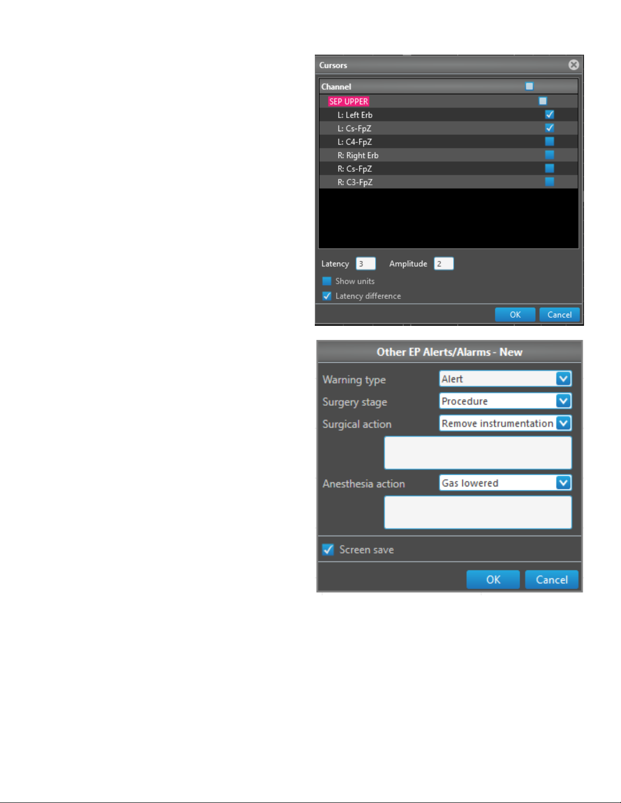
Monitoring and Review
Stack window
In the Stack window – select the channels for which cursors will be
visible.
Add alert/alarm
Add Alert/Alarm - Opens a dialog window used to add an alert or
alarm. The system generates a comment when the user creates an
alert/alarm.
Other right-click options
Save Building Average - Use the Save Building Average dialog to save
it without starting another average when used while the modality is
stopped.
Hide Channels – Use the Hide Channels dialog to select which
channels to show in the Stack window.
Cursors – Open the Cursors dialog to select the cursors for the
window.
More Replications/Less Replications – The system switches between
these two modes when the user selects one or the other.
Auto Hide Traces – When the user selects Auto Hide Traces, the system
only saves traces immediately before and after the selected comments
are visible.
Hide Trace – Hide selected highlighted traces. The system highlights
Traces when the user hovers the mouse pointer over them. Use the
Ctrl+left mouse button to select a single trace in the Stack window.
Use the Shift+Left mouse button to select the whole row in the Stack
window.
Unselect Traces – Unselect all selected traces in the Stack window.
Unhide Trace – Unhide the last hidden traces.
Unhide All Traces – Unhide all hidden traces.
Zoom Trace – Zoom the selected channel in the Stack windows.
Equalize Traces – Set the traces to their default positions.
Update Comment – Update a comment for modied peaks in the TOF
trace window.
Copy Window – Copy the window to the clipboard.
Markers – Open the Marker settings panel.
Place Marker – Open the Place Marker dialog.
Remove Marker – Remove the highlighted marker.
5-7 NIM-ECLIPSE™ E4 NS
Page 58

Monitoring and Review
NIM-Eclipse™ System Review Data screen
You can review saved data for any patient on the Review Data screen. Access the Review Data screen by clicking [Review Test] on the Run/
Modify Test Selection screen after opening the NIM-Eclipse™ System application.
1. System menu: Contains the Save As, Review Test, Close functions,
System Info, Help, User’s Manual, and Support data.
2. Layout tab: Click to select a layout to view the data.
3. Arrow icons: Use the arrows on the title bare to change the
sensitivity and timebase.
4. Review by menu: Allows users to select how data will be reviewed.
Data can be reviewed by Time, Triggered EMG, and EP. The time
markers for the viewed data can be noted in the Trace windows
on the Review screen.
5. Previous: Allow users to move to the previous saved data from the
current data.
6. Next: Allows users to move to the next saved data from the
current data.
7. Play/Stop icon: Play data for continuous review.
8. Baseline: Opens window to select channels and install baselines.
9. Electrodes and Channels: Opens window to provide electrode
names, denitions of recording channels and assignments of
stimulator outputs.
10. Minimize: Click to minimize window.
11. Maximize: Click to maximize window.
12. Close: Click to close the test.
13. Modalities Settings panel: Opens panel containing display and
recording options for data collected during a test.
14. Stimulus Setting panel: Opens Panel containing stimulation
parameters.
15. Secondary Windows Settings panel: Allows user to congure
secondary window settings.
16. Speakers: Enables users to congure audio settings for raw EMG
and various tones.
17. Print: Allows users to congure document output settings and
print reports.
18. Export Data Settings panel: Opens panel containing settings for
exporting the data.
19. Thumbnail Tray: All open and minimized windows for the selected
layout are kept in this tray.
20. Patient and Case Information: Displays a series of panels that
allow users to enter information about case including personal
Info, Case Sta, and Case Info.
21. System Settings panel: Allows users to congure system settings
such as the display language, units, and status bar displays.
22. Diagnostics: Displays settings for Calibration or Live windows.
23. Comments: Shows added comments to the test during the
procedure.
24. Chat: Shows chat messages during the remote monitoring
session.
25. Show/Hide settings panel: Shows/hides the settings column.
26. Resize Window: Click and drag this area to resize the monitoring
window.
27. Review Bar: Indicates the section of the saved data the system
is displaying. Adjust the slider to move forward or back in the
timeline. NOTE: If the user resumes data collection using the
Resume Test tab, the time increments on the review bar display
the last data collected until the review bar reaches the resume
data point . When the review bar reaches the new data point, all
new data appears.
5-8NIM-ECLIPSE™ E4 NS
Page 59

Monitoring and Review
Review a test
To select a test for review:
1. Click [Review Test] on the NIM-Eclipse™ System Main screen.
2. Click a patient test from the list.
3. Click [Review].
Previous/Next arrow control
The Previous/Next controls provide a means to manually review data. Use the arrow buttons to move to the Previous or Next data save from the
current time. The data displayed will depend upon the selected Review Mode. A beep at the beginning or end of the test will signal end-of-data.
Evoked potential data is displayed for each Last Average saved, and in the order the Last Average was acquired. If EP Traces were interleaved,
and especially if artifacting occurred during acquisition, EP Trace updates will not appear simultaneously.
EEG and Raw EMG data are moved forward or backward in 4 second steps for each click of the Next or Previous button, respectively. Use the
Play/Stop button to examine the EEG/EMG with more time detail.
Triggered EMG data are displayed in a similar manner to EP traces.
Press the F2 keyboard function key review a previous data, Press the F3 keyboard function key to review the next data.
Play/Stop Playback control
Press Play/Stop Playback to review data automatically. Click [Play] to begin reviewing data automatically starting from the current time.
Press the F4 keyboard function key to quickly toggle between play and stop.
Review test functional keys
Use the following functional keys on the keyboard to perform NIM-Eclipse™ System functions while review a test.
Key Review Test
F1 Help
F2 Previous
F3 Next
F4 Play/Stop
F5 Remote Sync Screen
F6 Remote Live On/O
F7 N/A
F8 Install baseline
F9 N/A
F10 Print screen
F11 Speaker On/O
5-9 NIM-ECLIPSE™ E4 NS
Page 60

Monitoring and Review
Print Settings
The system produces detailed reports in two types of formats. These formats are PDF and HL7. You may print data at any time during Test or
Review. The reports can be generated locally to a variety of supported printers. Reports can also be saved to a le and attached to email. You
may also select options relating to HIPAA and patient privacy.
Output
Use the printer and HL7 features to select the format of the test data
output. When the Printer tab is selected, the system displays the
printer menu, properties button, and a PDF Reports button. When the
HL7 tab is selected, the system displays the check box for View report
in HL7 File Viewer, and a HL7 Reports button.
The Printer eld allows users to select congured printer for system
printing. The Properties button displays the selected printer’s
properties. The PDF reports button allows users to open the default
folder where the PDF reports are saved.
If the View report in HL7 File Viewer is selected, the HL7 viewer is
open for every printed report.
Comment
The Comments text box is a free text area where users can add
additional comments to the report.
Select Reports
The Select reports section contains the Summary, Comment History,
Electrode Map, Trace, Stack, Spectra, and Patient Info report types. The
system outputs each of the enabled reports when the user clicks [Print
Report]. Clicking [Print Screen] creates a one-page report.
Professional report
The Template Section enables users to select predened report
templates for the professional report.
Click [Report Generator] to open the professional report program.
Report Header
The Report Header section includes text boxes used to add
information to the reports header. This information includes Hospital
Name, Department/Phone, Address, and City/State/Zip Code.
Legal Notice
The report header section also includes an area to enter a legal notice.
Click [Set Default] to restore the default legal notice.
Report Parameters
Report Parameter settings enable/disable additional features to the
report such as black and white print output, including the patient
name on the report header, including the legal notice, changing black
to white background, and fast print screen to PDF using the eDoc PDF
Pro printer without opening the save dialog for the report.
5-10NIM-ECLIPSE™ E4 NS
Page 61

Monitoring and Review
Export data settings
Export data in les can be used to export.
The Export to Data Settings tab enables users to export EP, Raw and
Triggered and EMG Trace data and EEG raw and spectral data to
third party programs such as Excel for o-line analysis. The Export
Data function is available when reviewing test data. The Export Data
function contains text elds and check boxes for the data listed below:
• Stack Markers: Exports the data corresponding to the EP Trace
Markers in the Stack.
• EP Channels: Exports the data corresponding to the EP Channels.
• Stack Only: Exports the data for each EP Trace data point in the
Stack only.
• Include samples: Include all sweep samples in the data le.
• Trig EMG Channels: Works the same way as EP channels for
Triggered EMG data. The user can select dierent modalities for the
output.
• Export: Creates the les with selected EP and Trig EMG export
selections.
• EEG Channels: Exports the data corresponding to the EEG
Channels.
• Fast Export: When selected, the system exports the EEG at a higher
speed and the screen is not updated.
• EEG Spectra: Starts/stops export of the EEG spectral data and
measurements. Data will be exported when EEG is played.
• EMG Channels: Starts/stops export of raw EMG data. Data will be
exported when Raw EMG is played.
• Include Patient Info: Includes the patient’s rst and last name and
ID with the exported data.
• Missing data: The system uses text when a marker is not dened
or not set.
5-11 NIM-ECLIPSE™ E4 NS
Page 62

Monitoring and Review
Report generator
The Report Generator enables you to create highly customizable reports with a minimum of typing by using templates.
Templates
A template is a set of forms with placeholders for data. Each template has exactly one form called MAIN – this is the form representing the entire
report. When printing, select the template and the Report Generator takes the template’s MAIN form and auto lls the data elds.
Once the MAIN form is automatically lled in, the document can be printed or further edited. In many cases the MAIN form may be all you
need to create a report. However, you may also have blocks of text that are specic to certain types of procedures. In this case, you can have a
template with a generic Main form and any number of additional secondary forms. You can insert these forms by dragging them from the forms
pane onto the document pane. As you drop these forms, all data elds will be automatically lled in.
If the template has a large number of additional forms, nding the right one may become dicult. To alleviate that, forms may be assigned a
group name. You can then use the FILTER button to show only the forms from a particular group. Use CLEAR FILTER to show all forms again.
5-12NIM-ECLIPSE™ E4 NS
Page 63
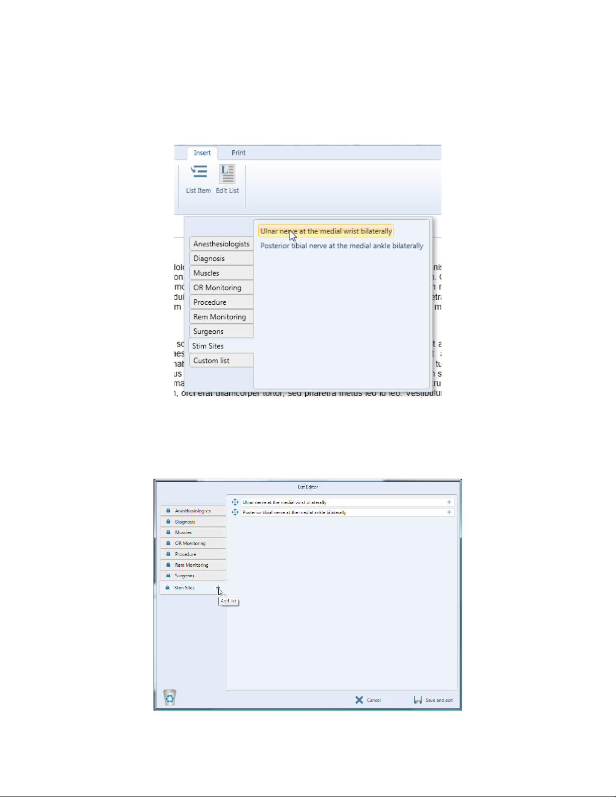
Monitoring and Review
Lists
Forms are complex blocks of text that may span multiple paragraphs, contain images, tables and data placeholders. However, there may be
simple chunks of text that you often use, such as muscle names, diagnoses etc. Instead of typing them, you can insert them from the INSERT /
LIST ITEM menu.
Lists are customizable via the EDIT LIST button. There are a few system lists that are xed. Their content can be edited but the lists themselves
cannot be deleted or reordered. In addition to them, you can dene any number of custom lists containing arbitrary data.
Lists are installed with some predened data.
Editing Lists
The button brings up the List Editor. Here you can add lists and add items to existing lists. You can also delete or reorder lists and items by
grabbing them by the handle and dragging them. To delete anything, drag it to the Recycle bin. You can delete items or entire lists. You can add
new lists and list members by clicking on the + or by pressing Enter while editing the previous item. Some lists have a little padlock instead of a
drag handle. Those are the system lists and they can’t be deleted or reordered. However, you can still add, remove and reorder the items in these
lists.
5-13 NIM-ECLIPSE™ E4 NS
Page 64

Monitoring and Review
Printing
Once the report is ready for printing, select the PRINT tab. In the print preview, the pages are shown exactly as they will print. Use the zoom
options to inspect your document and then click the PRINT button to send it to the printer. Alternatively, you can go back to the Edit tab for
further changes.
When the Report Generator is opened from within NIM-Eclipse™ System, it will ll the Main form and if no data is missing, will go directly to the
Print tab. If there is missing data, the Report Generator will go to the Edit tab since you most likely will need to edit the missing elds before
printing. The missing elds appear highlighted in yellow.
Saving the Report
You can save the report for further editing or printing. A saved report contains the report document itself, all the patient data and the template
to allow further editing of the saved report. When a saved report in opened the forms pane is displayed. Since the patient data is there as well,
you can drag-drop additional forms and they will be lled in on the y.
Formatting Text
The Edit tab contains the standard controls for font and paragraph manipulation. You may also include numbered or bulleted lists. The Insert tab
allows inserting a table, a page break or a list item. Inserting a page break in edit mode will add a horizontal line where the break will occur. To
see what the document will look like when printed, switch to the Print tab.
5-14NIM-ECLIPSE™ E4 NS
Page 65

Monitoring and Review
Report Tables
Tables can be used to display tabular data, but just as importantly, they can help you with the text layout.
To insert a table, position the cursor where you want the table to appear and click TABLE on the Insert tab. From the popup, drag the mouse to
determine the size of the table. Click the square that reects the desired size.
When a table is initially inserted, all of its columns are set to “auto width”. The table grid color is light gray which means that the grid won’t be
visible when printing; it is only shown in edit mode.
Table columns can either have a xed width (in inches) or have “auto width”. When a table contains both xed and auto width columns, the
layout works as follows. First, from the page width the widths of all xed columns are subtracted. The remaining space is divided equally
between the “auto width” columns.
You can control the column widths via the table context menu. To bring up the table context menu, right-click anywhere in the table. You can
add/remove rows, toggle between invisible and visible grid and set column widths.
5-15 NIM-ECLIPSE™ E4 NS
Page 66

Monitoring and Review
Example: Text Layout Using Tables
In the Report Generator, tables are used to control the layout of text. Suppose you want your company logo to appear on the top right of the rst
page. To do that, rst insert a table with 2 columns:
Next, copy the logo image from another program and paste it in the right column:
Next, copy the logo image from another program and paste it in the right column:
Columns are “auto width” by default, meaning that they take up the whole page and divide the available space equally. To adjust the right
column, position the cursor inside the column and right-click to bring up the table menu. Click the plus or minus buttons until the column is the
desired size.
The logo is placed. Note that the table grid is light gray, meaning the grid lines will not pint.
Anything can be inserted inside a table cell including formatted text with its own alignment, bulleted lists and even nested tables.
5-16NIM-ECLIPSE™ E4 NS
Page 67

Monitoring and Review
Create and Edit Report Templates
Templates are created and edited from within the Report Generator. Click the Edit Template button to toggle the Template editing mode on and
o.
The template editing mode opens a form editor window under the document window. In addition, each form in the forms pane has two buttons:
edit and delete.
Use the edit button to modify the form in the form editor. Use the delete button permanently removes the form.
The form editor controls are the same as the document window. The form editor has three additional controls: Group name, New form and Insert
eld.
You can resize the form editor up to the whole available space. The convenience of having the document window open as well is that you can
copy and paste between the two windows. For example, while writing a report if you type a paragraph that may be used in other reports you
can quickly add it to the template. To do so, toggle TEMPLATE EDIT, copy and paste your paragraph from the document into the form editor,
and toggle TEMPLATE EDIT again to close the form editor. Now your paragraph is included in the template and you can just drag and drop it if
needed in future reports.
Add Date Fields
If the paragraph you want to add to the template contains the patient name, we need to insert a data eld that will be lled with the actual
patient name for each report.
In the form editor, position your cursor where you want the data eld to be inserted. Click the INSERT DATA FIELD button.
A popup appears with a list of available data elds. Click on the data eld you need and it will be inserted in the form.
Since there are many data elds, it may be dicult to nd the one you need. If you know approximately what the eld name should be, just start
typing it in the search box and the selection will narrow down as you type.
5-17 NIM-ECLIPSE™ E4 NS
Page 68

Section 6: Remote Monitoring
In this section, you will be able to:
1. Start and End a Clinical System Remote Monitoring Session
2. Start and End a Remote System Remote Monitoring Session
3. Initiate a Text Chat Session
Page 69

Remote Monitoring
NIM-Eclipse™ System remote monitoring
The NIM-Eclipse™ System provides two exible approaches to remote monitoring depending upon the remote monitoring connection scheme.
Connections between the monitoring site (Clinical System) and the remote review site (Remote System) can be made through an Internet
connection.
The user can establish Remote monitoring using one of two available modes per session:
• Screen Share: Screen Share allows the remote view site users to view the Clinical System screen but they cannot change the screen layout,
view, or settings.
• Share Data: Share Data allows the data to be streamed from the Clinical System to the Remote System so that the remote review site user can
change their view of the data without changing the Clinical view.
• Text Chat: Text Chat allows monitoring site users to chat with remote review site users once a remote connection has been made between
the Clinical System and the Remote System, regardless of which remote monitoring mode the user selects. To save the chat log, right-click on
the chat window and export the text.
Clinical system remote monitoring session
To enable a remote connection from the monitoring site (Clinical System) to the remote review site (Remote System), do the following:
1. On the Main screen, click the Remote Monitoring icon.
2. In the Remote Monitoring Settings window, press [Enable networking].
Note: If desired, select the Auto-enable networking check box to automatically enable Remote Monitoring functions in the future. When
enabled, the IP address appears in the Remote Hosting section.
3. Ensure the remote user has an account on this computer. The system lists remote users in the Remote Monitoring User Accounts section.
If a user does not exist, select [+] to type a user name and password. If desired, select the Auto-Accept check box next to the user name to
enable that remote user to automatically connect to the Clinical System.
Notes:
• The user may manually add remote users by placing those users in the NimEclipseRemoteUsers Local Group in the Windows™*
operating system.
• To manually congure Auto-Accept, add the remote user to the NimEclipseRemoteUsersAutoAccept Local Group in the Windows™*
operating system.
• The user may use Active Directory credentials.
4. From the Hosting Services section, select the type of remote monitoring service, Share data, or the Screen Share screen.
5. The system is now ready to accept remote connections. Important: When the Remote System communicates with the Clinical System, if
a user has not been given permission to Auto-Accept, the monitoring site user must accept the remote review site user to complete the
remote monitoring service connection. Press [Accept] in the Remote Monitoring Settings window to accept the connection.
Note: Up to four remote users may connect to a single Clinical System simultaneously.
6. To disconnect a remote user, press [Disconnect].
When the remote connection is activated, the Remote Monitoring Settings window displays additional details under Remote Clients. The
additional details include; User, Connection Duration, Data Rate in Kpbs, and Response time in ms.
6-1 NIM-ECLIPSE™ E4 NS
Page 70

Remote Monitoring
Remote system remote monitoring session
To activate a remote connection from the remote view site (Remote System) to the monitoring site (Clinical System), do the following:
1. On the Main screen, press [Remote View]. The system displays the Remote Browser window.
Note: The software version of the Remote System must match the software version of the Clinical System.
2. When the system discovers clinical systems on the network, the systems appear in tabs on the Remote Browser screen. If there are no
clinical systems on the network, you can manually set up a system.
Note: On the Main screen, click the Remote Monitoring icon and deselect the Enable discovery check box if Discovery is not desired.
3. A. Select the appropriate system (for found systems).
B. If there are no found systems, click the add button (+) (to manually enter a system), then type your Host Name or IP Address, User Name,
Password, and then press [Request access].
4. Once the Clinical System accepts your connection you may select Start monitoring to begin your session.
Notes:
• If the user is using Share Data and wants to keep the Remote view layout synchronized with the Clinical system, ensure the user selects
the Synchronize automatically check box. If the user does not select Synchronize automatically, a red outline appears around the tab the
user is viewing on the Clinical side if that tab is not currently selected on the Remote side.
• If the user is using Screen Share and would like to t the Clinical view to your Remote screen, select the Auto-Fit View check box.
6-2NIM-ECLIPSE™ E4 NS
Page 71

Remote Monitoring
OR Time
Remote View displays “OR Time”, which is operating room live time. Remote View also displays the remote locations live time on the status bar.
If the network bandwidth is low and data cannot be transferred on time, the delay between displayed data at the remote location and the data
in the operating room increases. The remote location can detect the increased delay by observing the dierence between the OR Time and the
remote location live time.
Text chat
To create a text chat session, activate a connection between the Clinical System and the Remote System, and then do the following:
1. Click the Chat tab in the Remote Monitoring Settings window.
2. Type the text you want to send in the entry eld, then click [Send].
6-3 NIM-ECLIPSE™ E4 NS
Page 72

Remote Monitoring
Troubleshooting remote connections
1. Ensure a network connection is possible between the two systems to be connected. If the systems are not on the same network, the user
can use a Virtual Private Network. Consult the Information Technology department at your facility.
2. Ensure each side has set the correct date, time, and time zone.
6-4NIM-ECLIPSE™ E4 NS
Page 73

Section 7: System Information
In this section, you will be able to:
1. Clean and Maintain the NIM-Eclipse™ System
2. Locate User Assistance
3. View the Limited Warranty
4. View Technical Specications
5. View the Guidance and Manufacturer’s Declaration - Electromagnetic Immunity
6. Troubleshoot
7. View Symbols
Page 74

System Information
Sterility
This device is provided NON-STERILE and is REUSABLE.
Cleaning and maintenance
Cleaning
1. Disconnect all power cords from system components.
2. Preparation of NIM Insert Earphones
i. Discard the single-use earbuds.
ii. Replace the velcro strips covering the earphone velcro pads if organic soil contamination is visible on the velcro strips. If soil is visible
directly on the velcro pads, discard the earphone set.
3. Prepare a solution of one of the following detergents in tap or puried water and at the temperature and concentration within ranges
recommended by the detergent manufacturer:
i. a neutral (pH 6.0–8.0) enzymatic detergent
ii. a mild-alkaline (pH 8.0–11.0) non-enzymatic detergent
During application, the temperature of the detergent solution shall not exceed 40°C (104°F).
4. Clean the system components and cords by wiping their accessible surfaces with a soft, lint-free cloth dampened with the prepared
detergent solution. Wipe in a single direction and away from vents and crevices until surfaces are visibly clean.
5. If residual soil is observed in a hard-to-reach area, clean the aected area with a non-abrasive, soft-bristled brush moistened with the
detergent solution until the area is visibly clean.
6. Wipe accessible surfaces of the system and cords with a soft, lint-free cloth moistened with puried water.
7. If any areas were cleaned using a brush, rinse these areas with a clean soft-bristled brush moistened with puried water.
8. Dry all accessible surfaces of the system and cords by wiping them with a dry lint-free cloth. Allow moisture in any hard-to-reach areas to
air-dry.
Disinfection
1. Prior to disinfection, ensure that the system has been cleaned as instructed above and that all power cords remain unplugged.
2. Wipe surfaces of the reusable system components and cords using a sterile lint-free cloth soaked with one of the following disinfectant
solutions:
i. 70% isopropyl alcohol
ii. 0.5% accelerated hydrogen peroxide
iii. 0.5% sodium hypochlorite (bleach).
3. Do not allow the solution to penetrate vents or access electrical components.
4. Wipe in a single direction and away from vents and crevices.
5. Fold the wipe over to access hard-to-reach areas.
6. Allow the disinfectant to remain in contact with system’s surfaces and cords for at least 10 minutes. Re-apply the disinfectant to the areas
where air-drying of the disinfectant has occurred.
7. For disinfection using bleach: After the specied disinfectant contact time, remove disinfectant residuals by wiping system surfaces as
described above, using a sterile, lint-free cloth moistened with puried water.
8. Before re-using or storing the system, allow the surfaces to air-dry or wipe o visible moisture with a dry, sterile, lint-free cloth.
Disposal
Dispose of this device in accordance with hospital, administrative, or government policies.
Technical support
For further information regarding the use of this product or to report any problems, please contact Medtronic Xomed using the appropriate
information provided on the contact information card packaged with each device; or contact your local distributor.
Limited warranty
A. This LIMITED WARRANTY provides assurance for the customer who purchases a Medtronic Xomed Product (hereinafter the “Product”) that
should the Product fail to function to Medtronic Xomed’s published specications during the term of this LIMITED WARRANTY (one year from
the date of shipment for new Product, 90 days from date of shipment for refurbished or used Product), Medtronic Xomed will either replace,
repair, or issue a credit (adjusted to reect the age of the Product) for the Product or any portion thereof. This LIMITED WARRANTY is extended
only to the buyer purchasing the Product directly from Medtronic Xomed or from its aliate or its authorized distributor or representative.
B. To qualify for this LIMITED WARRANTY, the following conditions must be met:
1. The Product must be used on or before its “Use By” or “Use Before” date, if applicable.
2. The Product must be used in accordance with its labeling and may not be altered or subjected to misuse, abuse, accident or improper
handling.
3. Medtronic Xomed must be notied in writing within 30 days following discovery of a defect.
7-1
NIM-ECLIPSE™ E4 NS
Page 75

System Information
4. The Product must be returned to Medtronic Xomed within 30 days of Medtronic Xomed receiving notice as provided for in (3) above.
5. Upon examination of the Product by Medtronic Xomed, Medtronic Xomed shall have determined that: (i) the Product was not repaired or
altered by anyone other than Medtronic Xomed or its authorized representative, (ii) the Product was not operated under conditions other
than normal use, and (iii) the prescribed periodic maintenance and services have been performed on the Product.
C. This LIMITED WARRANTY is limited to its express terms. THIS LIMITED WARRANTY IS IN LIEU OF ALL OTHER WARRANTIES, EXPRESSED OR IM-
PLIED WHETHER STATUTORY OR OTHERWISE, INCLUDING ANY IMPLIED WARRANTY OF MERCHANTABILITY OR FITNESS FOR A PARTICULAR
PURPOSE. In no event shall Medtronic Xomed be liable for any consequential, incidental, prospective or other similar damage resulting from a
defect, failure, or malfunction of the Product, whether a claim for such damage is based upon the warranty, contract, negligence or otherwise.
D. The exclusions and limitations set out above are not intended to, and should not be construed so as to, contravene mandatory provisions of
applicable law. Users may benet from statutory warranty rights under legislation governing the sale of consumer goods. If any part or term of
this LIMITED WARRANTY is held by any court of competent jurisdiction to be illegal, unenforceable, or in conict with applicable law, the validity of the remaining portion of the LIMITED WARRANTY shall not be aected, and all rights and obligations shall be construed and enforced as
if this LIMITED WARRANTY did not contain the particular part or term held to be invalid.
NIM-ECLIPSE™ E4 NS
7-2
Page 76

System Information
Technical specications
System overview
Multitasking: Simultaneous, acquisition, processing, display, saving, reviewing and printing or faxing of data.
Multimodality: Simultaneous monitoring of EEG, evoked potentials and EMG.
Interleaving: Up to16 stimuli per test.
Sets: Up to 8 multimodality sets can be dened within a test protocol.
User interface:
Data collection modes: Free running, averaged or triggered. All trace parameters (lter, amplier input, artifact rejection, timebase, display scale, etc.) are fully
Data presentation:
Vital signs: Import up to 24 physiological measures from an external physiological monitor using serial data link.
Display: Any data window can be viewed at any time.
Trace window: Displays continuous EEG and EMG, averaged EP, and triggered EMG. Up to 128 traces can be displayed.
Stack window: Displays EP and triggered EMG traces epochs stacked in time.
Spectral window: Displays up to 32 processed channels of EEG in CSA, DSA or CDSA formats.
Numerics window: Displays absolute or relative calculated values of measurements.
Settings panel: Displays key test parameters, which can be quickly changed during the test.
Cursors: Absolute and dierential in all EP and triggered EMG trace and stack display windows.
Saving data: Data can be saved manually or automatically as continuous EEG, free run EMG, triggered EMG, updated averaged EP, Screen snapshots.
Data review: Previously saved data can be reviewed while monitoring. Review data locally or remotely via network or Internet.
Remote Monitoring: Screen and data transfers with text chat.
Test protocols: Standard test protocols are provided and can be modied and saved by user.
Comments: Preset and free form text entry saved with time marks.
Quick reports: Automatically generated for every test.
Speaker output: Any selected EMG channel.
Mouse with “notebook“ pages and Windows™* style controls.
user adjustable and independent.
Data are displayed in 4 window types: Traces, Stack, Spectral, Numerics. Windows™* may be split, resized and moved.
Video: Up to two inputs. Synchronized to neurological data.
Help: Available
Digital preamplier module
Number: 2 modules
Channels: 32 (16 channels per preamplier module)
Active inputs: 64 (32 inputs per preamplier module)
Leads: Auto switched
Indicators: LEDs indicate active electrode inputs
Auto recovery: 0.5 sec recovery to baseline after overload
Amplier Input: ± 160 μV to ±25 mV
Noise: 20 nV√ Hz, < 2.0 μV p-p (0.2 – 200 Hz)
CMRR: > 100 dB @ 60 Hz
Impedance: > 1000 Mohms
DC input: ± 0.75 V
Bandwidth: 1 Hz – 4 KHz
A/D converter 20KHz/channel, 16 bit
External digital
interface port:
Interface: Proprietary
Isolated, RS232, 5V, 155Kb
Interfaces to Nonin Xpod™* pulse oximetry (not approved in Brazil and Canada)
7-3
NIM-ECLIPSE™ E4 NS
Page 77

Digital preamplier module
Isolation: Optical
Safety: Meets or exceeds IEC60601-1
Environmental: Splash proof
Dimensions: Size: 5.5 X 8.8 X 1.5 in
Weight: 1.5 lb
Pulse oximeter module (not approved in Brazil and Canada)
Oximeter device:
Oximeters per System 2. One per each DAQ916 / 945DAQ916 Digital Preamplier
Population: Adult, pediatric and neonatal
Anatomical sites: Fingers and toes
Oxygen saturation
Pulse rate range: 18 to 321 pulses per minute
Measurement
wavelengths:
SpO2 accuracy: No motion Disposable Sensor
Pulse rate accuracy: No motion (18 – 300 BPM) Disposable Sensor
Power: Isolated, supplied by Digital Preamplier Module
Dimensions: Size: 2.1 x 0.8 x 0.6 in
Nonin Xpod™* Patient Cable Oximeter Rev 29+
0 to 100%
range:
Red – 660 Nanometers @ 3mw nominal
Infrared – 910 Nanometer @ 3mw nominal
Adults, Pediatrics +/- 3 digits
Neonates +/- 4 digits
Motion
Adults, Pediatrics +/- 3 digits
Neonates +/- 4 digits
Low Perfusion
Adults, Pediatrics +/- 2 digits
Neonates +/- 3 digits
Adults, Pediatrics +/- 3 digits
Neonates +/- 3 digits
Motion (40 -240 BPM)
Adults, Pediatrics +/- 5 digits
Neonates +/- 5 digits
Low Perfusion (40 -240 BPM)
Adults, Pediatrics +/- 3 digits
Neonates +/- 3 digits
Cable length: 6 ft
Weight: 75 g
System Information
NIM-ECLIPSE™ E4 NS
7-4
Page 78

System Information
Evoked potential monitoring
Channels: 32
Modes: BAER, SEP, VEP, D Wave, Phase Reversal
Averaging: Grand averaging, Moving average
Traces: Up to 64
Low pass lter: 50 – 4000 Hz; 12 or 24 dB/oct
High pass lter: 1 – 500 Hz; 6 or 12 dB/oct
Smoothing lter: Zero phase bandpass or 3, 5, 7, 9, 15, 25 pt smoothing lters
Notch lter: 50 or 60 Hz
Sweeps: 1 – 10000
Sweep length: 1 – 5000 msec
Timebase: 0.1 – 1000 msec/div, 10 divisions
Points/sweep: 10 – 1000 based on Sweep Length
Artifact rej: 0 – 100% of Full Scale, 0-40 msec delay
Stimulus delay: ± 0.5 sweep length
Trace display: Current sweep, building average, last average, odd/even averages, up to 1024 replications and baselines per trace
Markers: Up to 8 per trace
EEG monitoring
Collection: Continuous, free running
Channels: 32
Sampling Rate: 250 samples/sec
Traces: Up to 64
Timebase: 5, 10, 15, 30 or 60 mm/sec and 0.2, 0.5, 1.0, 2.0 sec/div
Artifact rejection: 0 – 100% full scale
Low pass lter: 10 – 80 Hz; 12 or 24 dB/oct
High pass lter: 1 – 20 Hz; 6 or 12 dB/oct
Notch lter: 50 or 60 Hz
Processing: Absolute and relative power, rms voltage, mean and peak frequency, asymmetry and coherence in 8 user dened bands, burst
FFT epoch averaging: 1 – 30 epochs; moving averaged; 2 sec epochs
suppression ratio, spectral edge frequency
EMG monitoring
Collection: Continuous, free running and signal or stimulus triggered
Channels: 32
Traces: Free run EMG: Up to 32
Triggered EMG: Up to 64
Raw EMG timebase: 10, 20, 50, 100, 200, 500, 1000, 2000 msec/div, 10 divisions
Sweep length: 1 – 5,000 msec
Low pass lter: 50 – 4,000 Hz; 12 or 24 dB/oct
High pass lter: 1.0 – 500 Hz; 6 or 12 dB/oct
Notch lter: 50 or 60 Hz
Pre-Stim delay: +/- 0.5 sweep length
Audio output: Selectable; any or all EMG channels
Trigger tones: Unique frequency tone identies the triggered channel with highest amplitude.
Muting: Automatic muting of electrocautery noise using Mute Probe or ESU software detection.
7-5
NIM-ECLIPSE™ E4 NS
Page 79

Speech mapping
Stimulation: High electrical stimulus
Stimulation duration: 1 to 60 seconds
Stimulation general
Modes: Repetitive, non-repetitive, single sequence, external trigger in
Interleaving: Up to 16 stimuli
Trigger source: Internal, external.
Ext trigger: TTL compatible voltage level.
Trigger edge: Rise, fall.
Presentation: Continuous, paused
Stimulus rate: 0.1 – 100 stim/sec
Train rate: 1 – 10000 Hz
Train count: 1 – 200
Stim interval: Fixed, random
Randomness: 0 to 30 %.
Elec stim. extender
dimensions:
Safety: Meets or exceeds IEC60601-1
Size: 5 X 5 X 1.3
Weight: 0.4 lb
Electrical high level
Output sites: 8 sites/extender. Up to 2 stim extenders/system.
Stimulus mode: Single, train, double train, unilateral, bilateral
Stimulus type: Constant current or voltage
Polarity: Normal, inverse, biphasic
Pulse Duration: 25 - 1000 μsec
High Intensity: 0 – 20 mA in 0.1 mA steps, 400 V max;
21 – 100mA in 1mA steps, 400V max
0 – 20V in 0.1V steps into 4K Ohm load
21 – 400 V in 1 V steps into 4K Ohm load.
Monitoring: On-screen display of patient current
Electrical slow charge MEP
Output sites: 2 sites/extender.
Stimulus mode: Single, train, double train
Train Rate: 1 - 10000 Hz
Train Count: 1 – 9 monophasic, 1 – 7 biphasic
Stimulus type: Constant voltage
Polarity: Normal, inverse, biphasic
Pulse Duration: 100 - 500 μsec
Intensity: 0 – 600 V in 1 V steps into 4K Ohm load. 175mA max.
Monitoring: On-screen display of patient current
Safety: Safety limits for stimulation parameters
Auto shutdown when parameters exceed safe limits.
Minimum time to re-stimulate 0.5 second
System Information
NIM-ECLIPSE™ E4 NS
7-6
Page 80

System Information
Electrical fast charge MEP
Output sites: 2 sites/extender.
Stimulus mode: Single, train, double train
Train Rate: 1 - 10000 Hz
Train Count: 1 - 10 monophasic, 1 – 8 biphasic
Double Train Sum
Count:
Double Train
Interval:
Stimulus type: Constant voltage
Polarity: Normal, inverse, biphasic
Pulse Duration: 30 – 75 μsec Rectangular pulse
Intensity: 0 – 1000 V in 1 V steps 1000 mA max. into 1K Ohm load
Monitoring: On-screen display of patient current
Safety: Safety limits for stimulation parameters
1 - 10 monophasic, 1 – 8 biphasic
6 - 500 msec
Auto shutdown when parameters exceed safe limits.
Minimum time to re-stimulate 0.5 second
Pedicle screw integrity
Output Sites 8 sites/extender. Up to 2 stim extenders/system.
Modes: Automatic and Manual
Stimulus mode: Single, train, double train
Stimulus type: Constant current
Polarity: Normal, inverse, biphasic
Pulse Duration: 25 - 1000 μsec
Rate: 0.1 – 100 Stim/sec; Default = 3 Stim/sec
Manual Mode
Intensity:
Manual Mode
Intensity Step:
Automatic
Stimulation
Intensity
Automatic Response
Criteria
Pass Fail Criteria: Fail if Below: 1 - 30 mA
Monitoring: On-screen display of patient current
Indicators: Tone, voice
Results: Auto saved comments with spinal level, intensity and results (Pass/Fail/No Decision)
0 – 100mA into 4K Ohm load
0.1 mA: 0 – 20 mA
1 mA: 21 – 100 mA
Start: 0.1 – 10 mA
End: 1 - 60 mA
Start Time: 0 – 40 ms
Response Replications: 3
Pass if Above: 3 - 30 mA
7-7
NIM-ECLIPSE™ E4 NS
Page 81

Neural proximity
Output Sites 8 sites/extender. Up to 2 stim extenders/system.
Modes: Automatic
Stimulus mode: Single, train, or double train
Stimulus type: Constant current
Polarity: Normal, inverse, biphasic
Pulse Duration: 25 - 1000 μsec
Rate: 0.1 – 100 Stim/sec; Default = 3 Stim/sec
Auto Intensity Max 3 - 60mA
Response Criteria Start Time: 0 – 40 ms
Monitoring: On-screen display of patient current
Indicators: Tone, 3 frequencies
Electrical low level
Output site: 1 site/extender. Up to 2 stim extenders/system.
Stimulus mode: Single, train, or double train
Stimulus type: Constant current or voltage
Polarity: Normal, inverse, biphasic
Duration: 25 - 500 μsec
Intensity: Low level: 0 – 4.0 mA/V in 0.01 mA/V steps into 10K Ohm load
Monitoring: On-screen display of patient current
System Information
Audio
Stimulus Mode: Left, right or bilateral. Single or train.
Stimulus Rate: 0.1 – 100 per second.
Type: Tone, click
Polarity: Rarefaction, condensation, alternating.
Intensity: 0 to 134 dB SPL Tone burst, 134 dB SPL Click
Steps: 1 dB
Click duration: 50 to 1000 μsec in 50 μsec steps.
Tone freq.: 0.250 to 8 KHz.
Plateau: 0 – 1600 cycles
Onset ramp: 0 – 320 cycles
Tone envelope: Rectangular, Linear, Hanning, Hamming, Blackman, Blackman-Harris
Calibration: SPL or nHL
Masking Noise: Broadband white noise.
Noise Intensity: 0 to 125 dB SPL absolute or relative to stimulus intensity.
Transducers: ER-3A insert or TDH 39 earphones.
Earphone delay: 0 - 1000 μsec
Visual
Stimulus Mode: Left, right or Bilateral. Single or train.
Flash duration: 1-10 msec
Rel intensity: 0-100 %
Pk luminous int: 3 X 5500 mcd
Wavelength: White light
NIM-ECLIPSE™ E4 NS
7-8
Page 82

System Information
External stimulus trigger output
Output sites: 2
Stimulus mode: Single, train, unilateral or bilateral
Duration: 100 μsec
Output: TTL compatible
System architecture
Central CPU i5 or higher, 1.4+ GHz, 4GB+ RAM
Operating system:
Platform: Desktop or laptop
Graphics resolution: 1024 x 768 or higher
Display size: 15” or larger
EMG speaker: 1 internal
Mass storage: 64+ GB HDD/SSD, R/W DVD
Printer:
Communications: Network compatible
Power: 100-240 VAC, 50-60Hz, < 300W
64-bit Windows™* 7/10 for System; 32/64-bit Windows™* 7/10 for Reader.
Any Windows™* supported printer
Operational environment
temperature range:
Operating
Humidity: 30-70% RH non-condensing
Atmospheric
pressure range:
Mode of operation: Continuous duty
Classications
Type of Protection against electrical shock: Class I Medical Device per IEC/EN60601-1
Degree of protection against electrical shock: Type BF applied parts
Ingress of water, dust, or solids IEC 60529: IPX0
Use with ammable anesthetics mixtures, with air,
10 to 40 ºC (Operating)
700 kPa to 1060 kPa
oxygen, and nitrous oxide:
Power Outlets
System Controller (ECLC/945ECLC): 200VA
Power Controller (P216, 945P216, P226): 300VA (total combined load from 4 outlets)
Not suitable for use in the presence of ammable anesthetic mixtures and/or oxygen-rich environments
7-9
NIM-ECLIPSE™ E4 NS
Page 83

System Information
Guidance and manufacturer’s declaration – electromagnetic emission and immunity
Environment of intended use: professional healthcare facility environment.
Guidance and manfacturer’s declaration - electromagnetic emissions
The NIM-Eclipse™ is intended for use in the electromagnetic environment specied below. The customer or the user of the NIM-Eclipse™ should assure that it is
used in such an environment.
Emissions test Compliance Electromagnetic environment – guidance
RF emission
CISPR 11
RF emission
CISPR 11
Harmonic emissions
IEC 61000-3-2
Voltage uctuations/icker
emissions
IEC 61000-3-3
Note: The emissions characteristics of this equipment make it suitable for use in industrial areas and hospitals (CISPR 11 class A). If it is used in a residential
environment (for which CISPR 11 class B is normally required) this equipment might not oer adequate protection to radio‐frequency communication services.
The user might need to take mitigation measures, such as relocating or re‐orienting the equipment.
Part I
The NIM-Eclipse™ is intended for use in the electromagnetic environment specied below. The customer or the user of the NIM-Eclipse™ should assure that it is
used in such an environment.
Immunity test IEC/EN 60601-1-2 test level Compliance level Electromagnetic environment - guidance
Electrostatic discharge (ESD)
IEC 61000-4-2
Electrical fast transient/burst
IEC 61000-4-4
Surge
IEC 61000-4-5
Voltage dips, short interruptions
and voltage variations on
power supply input lines
IEC 61000-4-11
Power frequency (50/60 Hz)
magnetic eld
IEC 61000-4-8
Note: UT is the a.c. mains voltage prior to application of the test level.
Group 1 The NIM-Eclipse™ uses RF energy only for its internal function. Therefore, its RF emissions are
Class A
Class A
Complies
very low and are not likely to cause any interference in nearby electronic equipment.
The NIM-Eclipse™ is suitable for use in all establishments, other than domestic and those
directly connected to the public low-voltage power supply network that supplies buildings
for domestic purpose.
Guidance and manufacturer’s declaration – electromagnetic immunity
±8 kV contact
±15 kV air
±2kV for power supply lines
±1kV for input/output lines
±1kV line to line
±2 kV line to earth
0 % UT (100 % dip in UT) for 0.5 cycle
at 0°, 45°, 90°, 135°, 180°, 225°, 270°,
and 315°
0 % UT (100 % dip in UT) for 1 cycle
at 0°
70 % UT (30 % dip in UT) for 0.5 sec
at 0°
0 % UT (100 % dip in UT ) for 5 sec 0 % UT (100 % dip in UT ) for 5 sec
30 A/m 30 A/m
±8 kV contact
±15 kV air
±2kV for power supply lines
±1kV for input/output lines
±1kV line to line
±2kV line to earth
0 % UT (100 % dip in UT) for 0.5 cycle
at 0°, 45°, 90°, 135°, 180°, 225°, 270°,
and 315°
0 % UT (100 % dip in UT) for 1 cycle
at 0°
70 % UT (30 % dip in UT) for 0.5 sec
at 0°
The relative humidity should be at least 5%.
Mains power quality should be that of a typical commercial
or hospital environment.
Mains power quality should be that of a typical commercial
or hospital environment.
Mains power quality should be that of a typical commercial
or hospital environment. If the user of the NIM-Eclipse™
requires continuous operation during power mains
interruptions, it is recommended that the NIM-Eclipse™
be powered from an uninterruptible power supply or a
battery.
Power frequency magnetic elds should be at levels
characteristic of a typical location in a typical commercial
or hospital environment.
NIM-ECLIPSE™ E4 NS
7-10
Page 84

System Information
Part II
Guidance and manufacturer’s declaration - electromagnetic immunities
The NIM-Eclipse™ is intended for use in the electromagnetic environment specied below. The customer or the user of the NIM-Eclipse™ should assure that it is
used in such an environment.
Immunity test IEC/EN 60601-1-2 test level Compliance level Electromagnetic environment - guidance
Conducted RF
IEC 61000-4-6
3Vrms
150kHz to 80MHz
6 Vrms
150 kHz to 80 MHz in ISM bands
3Vrms
150kHz to 80MHz
6 Vrms
150 kHz to 80 MHz in ISM bands
Portable RF communications equipment (including
peripherals such as antenna cables and external
antennas) should be used no closer than 30 cm
(12 inches) to any part of the NIM-Eclipse™, including
cables specified by the manufacturer. Otherwise,
degradation of the performance of this equipment
could result.
Radiated RF
IEC 61000-4-3
NOTE These guidelines may not apply in all situations. Electromagnetic propagation is aected by absorption and reection from structures, objects and people.
3V/m
80MHz to 2.7 GHz
9 – 28 V/m
Spot frequencies
385 MHz to 5.785 GHz
Pulse modulation
3V/m
80 MHz to 2.7 GHz
9 – 28 V/m
Spot frequencies
385 MHz to 5.785 GHz
Pulse modulation
Portable and mobile RF communications equipment
should be used no closer to any part of the NIM-Eclipse™,
including cables, than the recommended separation
distance calculated from the equation applicable to
the frequency of the transmitter.
Recommended separation distance
d = (6/E) √P
Where P is the maximum output power rating of the
transmitter in watts (W) according to the transmitter
manufacturer, E is the immunity test levels in volt per
meter (V/m), and d is the recommended separation
distance in meters (m).
Interference may occur in the vicinity of equipment
marked with the following symbol:
Recommended separation distances between portable and mobile RF communications equipment and the NIM-Eclipse™
The NIM-Eclipse™ is intended for use in the electromagnetic environment in which radiated RF disturbances are controlled. The customer or the user of the
NIM-Eclipse™ can help prevent electromagnetic interference by maintaining a minimum distance between portable and mobile RF communications equipment
(transmitters) and the NIM-Eclipse™ as recommended below, according to the maximum output power of the communications equipment.
Rated maximum
power of
transmitter
P (W)
380 MHz -
390 MHz
d = 0.22√P
430 MHz -
470 MHz
d = 0.22√P
Separation distance according to frequency of transmitter meters
704 MHz -
787 MHz
d = 0.67√P
800 MHz -
960 MHz
d = 0.22√P
1.7 GHz -
1.99 GHz
d = 0.22√P
2.4 GHz -
2.57 GHz
d = 0.22√P
5.1 GHz -
5.8 GHz
d = 0.67√P
0.01 0.03 0.03 0.07 0.03 0.03 0.03 0.07
0.1 0.07 0.07 0.21 0.07 0.07 0.07 0.21
1 0.22 0.22 0.67 0.22 0.22 0.22 0.67
10 0.7 0.7 2.12 0.7 0.7 0.7 2.12
100 2.2 2.2 6.7 2.2 2.2 2.2 6.7
For transmitters rated at a maximum output power not listed above, the recommended separation distance d in meters (m) can be determined using the
equation applicable to the frequency of the transmitter, where P is the maximum output power rating of the transmitter in watts (W) according to the
transmitter manufacturer.
NOTE These guidelines may not apply in all situations. Electromagnetic propagation is aected by absorption and reection from structures, objects and people.
7-11
NIM-ECLIPSE™ E4 NS
Page 85

System Information
Troubleshooting
For any troubleshooting items not corrected by the actions below, contact Technical Support.
Issue Possible Cause Action
Some or all traces are at Incorrect calibration waveform Switch to Calibration mode and calibrate.
Electro surgical cautery (ESU) is in use Wait until ESU stops.
Open or loose electrodes (including patient ground) Verify connectivity of electrodes.
Electrodes in wrong pin. Verify the electrodes are in the correct pins
Saturated ampliers. Artifact of FSI indicator appears. Increase Amplier Input.
Line related artifacts on some or all traces AC operated equipment. Periodic artifacts are caused by AC
Guest (remote PC) unable to connect to Host
(NIM-Eclipse™ System)
operated equipment. Large power line artifacts (between
100-1000 microvolts) can preclude evoked potential
monitoring and must be addressed prior to monitoring.
Electrostatic or Electromagnetic interference Remove power connections from equipment at
ECG contamination due to electrodes being placed over
artery or in close proximity to ECG signal
EMG interference or movement artifacts Consult anesthesiologist regarding anesthetic
Wireless connection is o. The PC has a wireless on/o switch on the
Wireless connection is on, but unable to connect to the
Internet.
Remote Monitoring is not enabled on the Host. From the Test screen, click the Remote
Unable to connect to IP address after virtual private
network is established.
according to the electrode chart.
Use the Live Mode to view input data so that
changes can be seen easily.
the wall outlet.
Disconnect power from microscope, electric
operating room table, blood warmer, heating
blanket, etc.
Test for faulty AC outlets or excessive leakage
current from perioperative equipment. Verify
that the system wall power outlet is well
grounded.
Use an alternate wall outlet.
Connect the system isopotential ground
terminal to a known good ground using a
heavy gauge wire to ensure zero voltage
dierence between equipment.
Set the Stimulation Rate to a non-integer
multiple of the power line frequency, for
example 4.3Hz.
Verify electrode impedances are lower than 5K
Ohms. Attempt to match impedances to less
than 2K Ohms.
Use a large, 2-3 cm² active area electrode for
patient ground.
Braid electrode leads to reduce
electromagnetic interference.
Minimize electrostatically induced interference
by changing the position of the Digital
Preamplier and/or electrode leads.
Reposition electrodes on aected channel(s)
agents used
Prevent electrode movement by securing to
the patient with tape
front, side, or on the keyboard layout. Conrm
that the switch is in the On position.
Click on the Wireless icon on the taskbar to
open available network selections. Conrm
that the preferred network is selected.
icon on the right side of the screen.
The Remote Monitoring Settings
panel appears. Press [Enable
Networking] to enable remote
monitoring.
Conrm that the 8000 port is open on the
rewall for both incoming and outgoing trac.
NIM-ECLIPSE™ E4 NS
7-12
Page 86

System Information
Issue Possible Cause Action
Guest does not have correct IP address. On the Test screen, click the Remote
The system displays the incorrect date / time
format on the user interface and on reports.
Excessive stimulus artifact High or unbalanced electrode impedance (may be on
Stimulation not delivered (measured current
does not equal set current)
Improper impedance values / failed impedance
test
Windows™* is not using the correct region format for date/
time.
stimulation, recording, or ground electrodes)
Stimulation and recording electrodes are overlapping or in
close proximity
Electrodes not properly connected If pre-gelled adhesive electrodes are used,
Stimulating electrode or probe connection or contact with
tissue
Current shunting Ensure electrode sites are not ooded
Stimulus Mode set to non-repetitive Verify Stimulus Mode setting
High electrode impedance (greater than 5K Ohms) or high
electrode imbalance (electrodes are not within 2K Ohms of
each other)
icon on the right side of the screen.
The Remote Settings panel appears.
The correct IP address appears in the
Remote Hosting section.
Close the NIM-Eclipse™ E4 System
software.
In the Windows™* Control Panel,
select Region and Language
settings.
On the Formats tab, select the
appropriate language from the
Format list.
On the Location tab, select the
appropriate country from the Current
Location list.
Click [Apply] and then click [OK].
Restart the NIM-Eclipse™ E4 System
Software.
Prep skin at stimulation and recording sites
Ensure proper electrodes connections and
placement
Verify electrode impedances are lower than 5K
Ohms. Attempt to match impedances to less
than 2K Ohms.
Place ground electrode between recording and
electrical stimulator electrodes
Increase distance between the recording and
stimulation electrode leads. If they must cross,
set leads at right angles.
Add Stimulus delay
Use Suppress Stimulus to blank out the
stimulus artifact
ensure the gel pads are not contacting each
other.
Verify electrode impedances are lower than 5K
Ohms. Attempt to match impedances to less
than 2K Ohms.
Ensure ush contact between stimulating
electrode or probe and nerve
Ensure proper connections and placement
Verify electrode placement
Ensure proper electrodes connections and
placement
Prevent electrode movement by securing to
the patient with tape
Prep skin at electrode sites
Remove and replace with new electrode. If
correcting high imbalance, remove and replace
electrode with highest impedance reading rst.
7-13
NIM-ECLIPSE™ E4 NS
Page 87

Issue Possible Cause Action
Electrode impedance is too low Ensure positive and negative electrode tips are
not contacting each other below surface of skin
Stimulator Error Message Faulty connection between stimulator and controller Check all connections
Replace stimulator module or cable
Stimulus settings exceed built-in safety limits Change stimulus parameters to reduce output
energy
High stimulator electrode impedance Ensure proper electrodes connections and
placement
System Information
NIM-ECLIPSE™ E4 NS
7-14
Page 88

System Information
Symbols
Do not dispose of this product in the unsorted municipal waste stream. Dispose of this product according to local regulations. See recycling.
medtronic.com for instructions on proper disposal of this product.
Equipotential Ground connector
AC Power
Type BF Applied Part
Fuse
Functional earth (ground)
Protective earth
High voltage. Do not use for Trans-Cranial stimulation
Power o / Power on
Follow instructions for use
General warning sign
Warning: Dangerous Voltage
ROHS - Environmental friendly use period - China (SJ/T11364-2006)
7-15
Conforms to ANSI/AAMI ES 60601-1, IEC/EN 60601-1.
Certied to CSA C22.2 No.60601-1
NIM-ECLIPSE™ E4 NS
Page 89

Page 90
EC REP
Medtronic Xomed
6743 Southpoint Drive North
Jacksonville, Florida 32216-0980
USA
medtronic.com
18008745797
medtronic.com
manuals.medtronic.com
Authorized Representative in the European
Community
Medtronic B.V.
Earl Bakkenstraat 10
6422 PJ Heerlen
The Netherlands
+31455668000
Europe/Middle East/Africa
Medtronic International Trading Sàrl
Route du Molliau 31
Case Postale 84
CH- 1131 Tolochenaz
Switzerland
+41218027000
Australia
Medtronic Australasia Pty Ltd
2 Alma Road
Macquarie Park, NSW 2113
Australia
© 2021 Medtronic
M003043C001 B
2021-02
Canada
Medtronic of Canada Ltd
99 Hereford Street
Brampton, Ontario L6Y 0R3
Canada
+19054603800
 Loading...