

Page 1

Guardian
®
RT
Continuous Glucose Monitoring System
REF MMT-7900
User Guide
Page 2
© 2005, Medtronic MiniMed. All rights reserved.
Guardian
®
, MiniMed® and Sen-serter® are registered trademarks of Medtronic MiniMed.
Com-Station™, Shower-Pak™, Solutions™ Software are trademarks of Medtronic MiniMed.
BD Logic™ is a trademark of Becton, Dickinson and Company
Detachol
®
is a registered trademark of Ferndale Laboratories, Inc.
Polyskin
®
is a registered trademark of the Kendall Healthcare Products Company.
CaviCide
®
is a registered trademark of the Metrex Research Corporation.
IV3000
®
is a registered trademark of Smith & Nephew, Inc.
YSI 2300 STAT Plus™ is a trademark of YSI Incorporated.
The Guardian RT System is covered by the following Patent Nos: 5,390,671; 5,391,250; 5,568,806; 5,586,533; 5,586,553;
5,777,060; 5,779,665; 5,786,439; 5,851,197; 5,882,494; 5,954,643; 6,093,172; 6,248,067; 6,293,925; 6,368,141; 6,418,332;
6,424,847; 6,462,162; 6,520,326; 6,607,509; DES 433,755.
The Guardian RT System is covered by other/pending patents.
6024979-012 072505
0459/0976
Page 3

Table of Contents i
Table of Contents
Chapter 1: Introduction ......................... 1
System Function....................................................... 2
System Components .................................................. 2
Glucose Sensor.................................................................... 2
Transmitter .......................................................................2
Monitor............................................................................. 3
Monitor Buttons ..................................................................3
Monitor Button Functions .......................................................4
Monitor User Guide Terms ......................................................4
Test Plug.......................................................................... 5
Sen-serter ........................................................................ 5
Availability............................................................. 5
Help..................................................................... 6
Record Keeping........................................................ 6
Warranty ............................................................... 6
User Safety .................................... ......................... 7
Indications for Use...............................................................7
Contraindications ................................................................7
Warnings...........................................................................8
Precautions........................................................................ 9
Adverse Reactions.............................................................. 11
Symptoms of Hypoglycemia .................................................. 11
Symptoms of Hyperglycemia ................................................. 12
Blood Glucose Meter........................................................... 12
Page 4

ii Table of Contents
Chapter 2: Getting Started .....................13
Quick-Reference Guide............................................. 13
Start-Up Process..................................................... 17
Installing the Batteries ....................................................... 17
Turning On the Monitor........................................................ 19
Turning Off the Monitor....................................................... 19
Home Screen.................................................................... 19
The Main Screens.................................................... 20
Programming the Monitor..................................................... 21
Setting the Language ......................................................... 22
Setting the Time Display Format ........................................... 23
Setting the Time and Date................................................... 24
Clearing the Glucose History ................................................ 26
Setting the Glucose Unit ..................................................... 29
Setting the Low Glucose Alert............................................... 30
Setting the High Glucose Alert.............................................. 33
Setting the Alert Type........................................................ 36
Entering the Transmitter ID ................................................. 37
Inserting the Sensor................................................ 39
Sensor Storage and Handling ................................................ 44
Sen-serter Maintenance...................................................... 44
Affixing the Transmitter............................................ 45
Searching for the Transmitter............................................... 46
Connecting the Sensor to the Transmitter ................................ 47
Sensor Initialization........................................................... 48
Sensor Calibration............................................................. 48
Calibration Pending........................................................... 50
No Sync ......................................................................... 50
Replacing the Glucose Sensor ..................................... 51
Removing the Sensor.......................................................... 51
Page 5

Table of Contents iii
Chapter 3: Routine Operation.................. 53
Glucose History ...................................................... 53
Entering Meter BG for Calibration................................ 55
BG Due................................................................ 56
Enter BG......................................................................... 57
Calibration Pending............................................................ 57
No Sync .......................................................................... 58
Replacing the Glucose Sensor ................................................ 58
Events.......................................... ........................59
Units of Insulin Taken ......................................................... 60
Carbohydrate Amount ......................................................... 61
Duration of Exercise ........................................................... 61
Other Events.................................................................... 62
Glucose Alarm History...............................................63
Search .................................................................65
Signals .................................................................65
The Snooze Option...................................................66
Chapter 4: Troubleshooting and Alarms ........ 67
List of Alarms........................................................ 68
No ID ............................................................................. 68
High .............................................................................. 69
Low............................................................................... 70
Check Sensor.................................................................... 71
Low Batt......................................................................... 72
Off/No Power................................................................... 73
Service C60/61 ................................................................. 74
Re Init............................................................................ 74
No Sync .......................................................................... 75
Cal Err............................................................................ 76
Key Held......................................................................... 77
Enter BG......................................................................... 77
Set Time......................................................................... 78
Replace Sensor ................................................................. 79
System Alarms....................................................... 80
Test Plug Procedure ................................................ 81
Page 6

iv Table of Contents
Chapter 5: Performance Characteristics .......83
Performance Results................................................ 84
Accuracy of Guardian RT Readings ............................... 85
Precision of Guardian RT Readings ............................... 89
Low and High Alerts................................................. 89
The Low Glucose Alert ....................................................... 90
The High Glucose Alert........................................................ 91
Guardian RT Sensor Performance and Calibration .............. 92
Affects of Calibration Frequency ................................. 94
Time-Elapsed Plots.................................................. 95
Chapter 6: System Maintenance ................99
Belt Clip .............................................................. 99
Installation ...................................................................... 99
Removal........................................................................ 100
Leather Case ....................................................... 100
Protection from Water ............................................100
Protection from Impact ...........................................101
Protection from High and Low Temperatures..................101
Cleaning the Monitor............................................... 102
Cleaning the Transmitter ......................................... 102
Cleaning the Sen-serter ........................................... 104
Interference from Electrical Equipment ........................ 105
Ordering Supplies................................................... 106
Product Specifications............................................. 107
FCC Notice for the Monitor ....................................... 110
FCC Notice for the Transmitter .................................. 110
Icon Table ........................................................... 111
Fixed Elements Table.............................................. 113
Appendix........................................ 115
Electromagnetic Compatibility Compliance Information .... 115
Glossary ........................................ 121
Page 7
1
Introduction
Congratulations on buying one of the most exciting devices in the field of diabetes care! The Medtronic
MiniMed Guardian® RT (Real Time) System (M MT-7900) continuously monitors glucose levels, provides real-
time glucose values, and gives high and low glucose alerts. The Guardian RT uses three separate components—Sensor, Transmitter, and Monitor—to measure and display glucose levels in persons with diabetes.
The Sensor is inserted in the abdomen in fluid under the skin (Interstitial Fluid) and is attached to the
Transmitter. The Transmitter takes information from the Sensor and sends it to the Monitor. The Monitor is
a device that can store this information for real-time review, or can download it to a personal computer
using a Medtronic MiniMed Com-Station™ (MMT-7301) and the Guardian Solutions™ Software (MMT-7315).
This information is used by you and your doctor to identify glucose patterns and to improve your diabetes
management.
We know you are ready to start, but before you do, please read the following user guide to learn all
about the Guardian RT. Chapter 1 gives a general overview of the system. Chapter 2 offers step-by-step
instructions to get you started. Chapter 3 explains the routine operation of the Guardian RT. Chapter 4
walks you through the system alarms and troubleshooting approach. Chapter 5 goes over performance
characteristics, and Chapter 6 covers system maintenance and other important information.
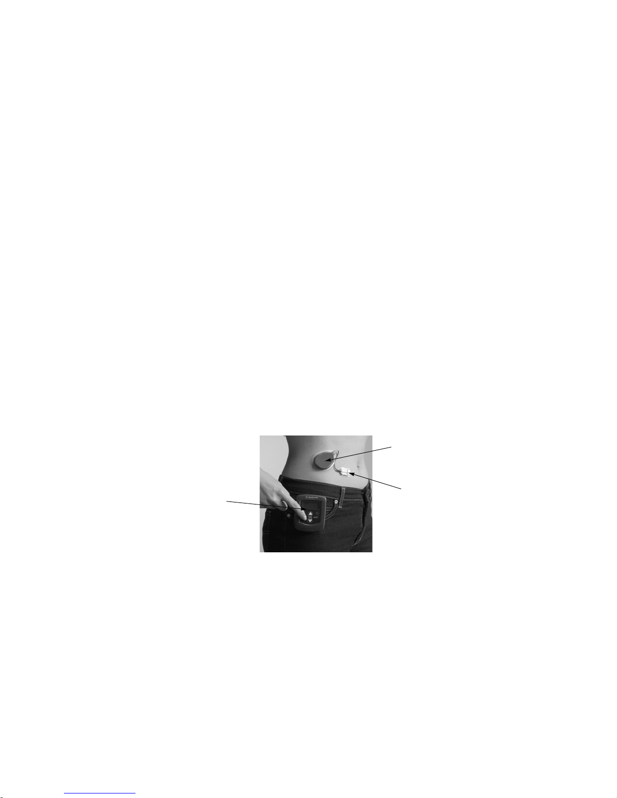
Figure 1.1
Monitor
Transmitter
Sensor
Page 8

2
System Function
The Guardian RT measures glucose levels in interstitial fluid: the fluid found between the body’s cells. It
is from this fluid that cells get oxygen and nutrients, including glucose. Glucose levels in interstitial fluid
typically match glucose levels in the blood. The system gives real-time interstitial fluid glucose values on
demand (updated every five minutes). The system also features low glucose and high glucose alerts that
are triggered once limits you have preset are reached. Data from the Sensor (which is placed under the
skin into the interstitial fluid) triggers the low blood glucose alert if your Sensor glucose value is less than
or equal to the preset limit. The high blood glucose alert is triggered if your Sensor glucose value is
greater than or equal to the preset limit. Glucose values are calculated and displayed based on the blood
glucose reference values entered periodically into the Monitor for calibration.
NOTE -
Before taking action based on glucose values or High and Low glucose alerts, check your blood
glucose using a home glucose meter available from your doctor or pharmacy.
System Components
Glucose Sensor
Figure 1.2
The Sensor (MMT-7002) is inserted through the skin into interstitial fluid. The Sensor
gives off a signal that is related to the amount of glucose in the interstitial fluid at the
insertion site. (See Figure 1.2.)
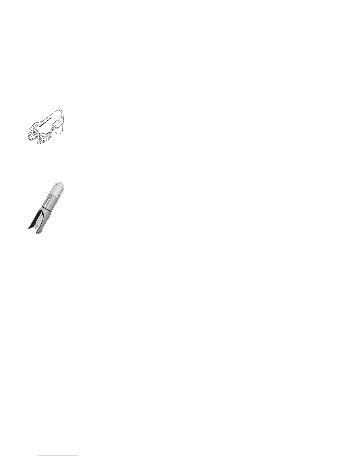
Transmitter
Figure 1.3
The Transmitter (MMT-7700) connects to the Sensor and is fixed to the skin with
medical tape. The Transmitter receives and processes signals from the Sensor,
and it sends the signals by radio frequency to the Monitor. (See Figure 1.3.)
Page 9

Introduction 3
Monitor
The Transmitter sends Sensor data in the form of radio signals to the Monitor (MMT-7901) about every 5
minutes. The Monitor stores this information and uses it to provide real-time glucose values and to trigger
low or high glucose alerts. This information can also be downloaded for analysis to a personal computer by
means of a Medtronic MiniMed Com-Station™ (MMT-7301) and the Guardian Solutions™ Software (MMT-7315).
The system is calibrated by entering into the Monitor blood glucose values from a home glucose meter. Six
hours before a meter BG entry for the purpose of calibration is due, the word CAL will appear on the Monitor
screen. This icon will remain on the display until you enter a meter value. If you do not enter a meter value
within 12 hours of the last entry, an ENTER BG alarm is triggered. This alarm is also triggered if a calibration
has not been done in the last 8 hours since the first calibration. For best performance, enter a meter value
every 6 hours. A minimum of one meter value must be entered at least every 12 hours into the Guardian RT
for the real-time glucose display and the low and high glucose alerts to work.
Monitor Buttons
The Monitor is controlled by 5 buttons. (See Figure 1.4.) Always press the Monitor buttons slowly and
firmly.
Figure 1.4
Up Arrow
Down Arrow
Backlight Button
Select
Button
Activate
Button
On/Off
Button
Display
Screen
Page 10

4
Monitor User Guide Terms
The following terms and icons are used to describe the Monitor in this User Guide:
➠ Press means to push and release the button.
➠ Hold means to push and keep pressure on the button.
➠ Flashing words or numbers (but not icons) on the screen mean that you can change this information
in the Monitor.
➠ Information that cannot be changed appears on the screen in characters that do not flash.
➠ Button names are always UPPERCASE and bold, e.g., ACT and SEL.
➠ Screen names are always UPPERCASE, e.g., HOME and HIGH.
Monitor Button Functions
This button turns the Monitor On or Off.
SEL
The SEL (Select) button scrolls through the menu screens. It is used
with the ACT button to clear alarms/alerts.
ACT
The ACT (Activate) button lets you make changes to programming,
save information to memory or clear alarms/alerts. You will hear a
beep when you press ACT to confirm the selection.
Up and Down
Arrows
The Up and Down arrows are used to change values or settings. Press
either arrow once to pick the next highest or lowest value. Hold down
either arrow to scroll through the list of values. Hold down either arrow
for more than 5 seconds to speed up scrolling. When you reach the
wanted value press ACT to set. If you do not press ACT within
10-20 seconds, the display will go back to the default screen.
Located on the Down arrow and used from the HOME screen, the
Backlight button turns On or Off the screen light, letting you see the
display at night or in dim lighting. The light will stay on for about 15
seconds after the last button press.
Page 11
Introduction 5
Test Plug
Figure 1.5
The Test Plug (MMT-7400) is a device used to troubleshoot the Guardian RT system. (See
Figure 1.5.) If there is a problem with the Guardian, it can give information that will tell if
the Sensor, Transmitter, or Monitor are working correctly. See Chapter 4:
Troubleshooting and Alarms for more details.
Sen-serter
Figure 1.6
The Sen-serter® (MMT-7500) is a spring-loaded reusable device that inserts the Sensor
(MMT-7002) at an angle under the skin and into the interstitial fluid. (See Figure 1.6.)
Availability
The Guardian RT and supporting products are available from Medtronic MiniMed and authorized
distributors.
Page 12
6
Help
Medtronic MiniMed provides a 24-Hour Product Help Line in the United States and Canada. The help line
is staffed with personnel trained in the set-up and use of the Guardian RT system, and they are able to
answer your questions. When calling, please have the Guardian RT system and this User Guide with you.
Record Keeping
A serial number is found on the back of the Monitor and on the top of the Transmitter. Please enter the
serial numbers and purchase date in the table below.
Warranty
Please read the enclosed warranty card carefully as it lists the terms of coverage.
Department Telephone Number
24-Hour Product Help Line
U.S. and Canada
800-MINIMED (800-646-4633) or
818-576-5555
International
Contact your local sales office
Medtronic MiniMed Website
www.minimed.com
Serial Number Purchase Date
Monitor:
Transmitter:
Page 13

Introduction 7
User Safety
Indications for Use
The Guardian RT is indicated for continuous or periodic monitoring of glucose levels in the fluid under
the skin, in adults (ages 18 and older) with diabetes mellitus, for the purpose of improving diabetes
management. It alerts if a glucose level falls below, or rises above, preset values. Values are not
intended to be used directly for making therapy adjustments, but rather to provide an indication of when
a finger stick may be required. All therapy adjustments should be based on measurements obtained using
a home glucose monitor and not on Guardian RT values.
The Guardian RT provides real-time glucose values that allow users to track patterns in glucose
concentrations and to possibly identify episodes of low and high blood glucose. It also stores the data so
that it can be analyzed to track patterns. Glucose data can be further downloaded to PC software for
analysis of historical glucose values.
Contraindications
Use of the Guardian RT is not recommended for persons whose impaired vision or hearing does not allow
full recognition of the Guardian RT signals and alarms/alerts.
The Sen-serter is not indicated for use with product other than the Glucose Sensor. Medtronic MiniMed
cannot guarantee this product’s safety and/or efficacy if other sets are used.
Page 14

8
Warnings
Monitor
The Monitor and Transmitter need to be kept within 6 feet (approximately 2.0 meters) of each other to
ensure that communication is not interrupted.
Transmitter
The Transmitter should be removed if irritation or reaction to the Transmitter tape develops.
The Transmitter should be disconnected from the Sensor while traveling on an aircraft, or if it interferes
with another transmitting device.
Sensor/Sen-serter
The Sensor may create special needs regarding your medical conditions or medications. Please discuss
these conditions and medications with your doctor before using the Sensor. Bleeding, swelling, irritation
and/or infection at the insertion site are possible risks associated with inserting the Sensor and may
result from improper insertion and maintenance of insertion site.
After insertion, wait 2-3 minutes before attaching the Transmitter to watch for bleeding at the insertion
site. If bleeding occurs, apply steady pressure using a sterile gauze or clean cloth for up to 3 minutes.
If bleeding stops:
1. Attach the Sensor to the system connector.
If bleeding does not stop:
CAUTION: Do NOT attach the Sensor to the system connector.
1. Remove the Sensor and discard.
2. Check the site for redness, bleeding, irritation, pain, tenderness, or inflammation and treat
accordingly.
3. Insert a new Sensor in a different location.
Page 15

Introduction 9
The Sensor should be removed if redness, pain, tenderness, or swelling develop at the insertion site, or if
you experience unexplained fevers. Check site often for these conditions and to make sure Sensor is still
in place, especially before going to bed and upon waking.
Confirm symptoms of low blood glucose and high blood glucose, as well as displayed glucose values and
alerts, with a home blood glucose meter available from your doctor or pharmacy.
The Sensor is sterile and non-pyrogenic unless the package has been opened or damaged. Do not use any
Sensor if its sterile package has been previously opened or damaged. Always inspect packaging for
damage prior to use. Do not use a Sensor that exceeds the expiration date printed on the package.
Remove plastic needle cover before inserting Sensor.
If Sensor is not securely placed in Sen-serter prior to insertion, pain or minor injury may occur.
Never point loaded Sen-serter toward any body part where insertion is not desired.
Precautions
Monitor
You should be trained by your healthcare professional on how to program and operate the Monitor and
respond to alarm/alert conditions before using the system.
Do not expose the Monitor to water. The Monitor should be set aside or placed in a Shower-Pak™ (MMT-
117) before doing activities in which the Monitor would be expected to get wet.
Contact sports or other activities may damage the Monitor and should be avoided. Prior to exercising,
make sure the Sensor is firmly attached.
If the Monitor shows a NO POWER alarm on the display, there will be an immediate shut-off as soon as the
alarm is acknowledged, and data collection will automatically stop. Batteries must be replaced
immediately to avoid the need for Sensor replacement and potential loss of data stored in memory. Upon
battery replacement, a SEARCH must be performed. (Refer to Searching for the Transmitter section in
Chapter 2: Getting Started.)
Page 16

10
Although the Monitor is tested and complies with the applicable standards, the use of the Monitor in
close proximity to strong electromagnetic sources, such as MRI equipment, television transmitters, highvoltage power lines, or high-power radio transmitters is not recommended.
Keep the Monitor in its leather case to protect against electrostatic discharges that are common in cold
and dry climates.
Transmitter
Establish a rotation schedule for choosing each new Transmitter site. Avoid sites that are constrained by
clothing, scar tissue, accessories or subjected to rigorous movement during exercise.
Sensor
Always wash hands with soap and water before opening the Sensor package and handling Sensor. After
opening the package, avoid touching any Sensor surfaces that will come in contact with the body. These
surfaces include: the Sensor, needle, connector adhesive surfaces and tape.
Prior to inserting the Sensor, select insertion site, and use antiseptic to cleanse site. Allow area to dry.
If you also wear an insulin pump, make sure that the Sensor insertion site is at least three (3) inches
(7.62 cm) away from the insulin infusion site. If you inject insulin, you should give injections at least
three (3) inches (7.62 cm) away from the Sensor insertion site. When replacing Sensor, select new
insertion site at least two (2) inches (5.08 cm) from previous site.
Do not insert Sensor through tape, and do not use sticky preps before insertion.
After inserting the Sensor and attaching the Transmitter, cover the Sensor site with sterile/occlusive
dressing, such as IV3000® (MMT-174).
Be aware that excessive perspiration can loosen dressing. Check dressing after any activity in which
excessive perspiration has resulted.
Establish a rotation schedule for choosing each new Sensor site. Avoid sites that are constrained by
clothing, scar tissue, accessories or subjected to rigorous movement during exercise.
Dispose of used Sensors and introducer needles in a sharps container after single use. Do not clean or
resterilize, and do not recap needle with Sensor needle cover.
Page 17

Introduction 11
Adverse Reactions
Operation of the Medtronic MiniMed Guardian RT requires the insertion of a Glucose Sensor into the skin.
Bleeding, swelling, bruising, or infection at the Sensor insertion site are possible risks of Sensor use. The
Sensor should be removed if redness, pain, tenderness, or swelling develop at the insertion site. The
Transmitter should be removed if irritation or a reaction to the Transmitter tape develops. In the event
of any adverse reaction associated with this system, U.S. and Canadian customers please contact your
doctor and the Product Help Line at 800-MINIMED (800-646-4633) or 818-576-5555. All other international
customers please contact your local sales office.
Symptoms of Hypoglycemia
Hypoglycemia (low blood glucose) may occur in persons with diabetes who take insulin or certain oral
medications. There are symptoms linked to low blood glucose that should not be ignored no matter how
mild they are, even if the Guardian RT does not display a low glucose value or give a low glucose alert. If
you have any of the following symptoms, take a meter blood glucose reading, and check with your doctor
before you treat:
➠ sweating ➠ confusion ➠ hunger
➠ dizziness ➠ headache ➠ blurred vision
➠ palpitations ➠ speech impairment
➠ trembling ➠ drowsiness
Page 18

12
Symptoms of Hyperglycemia
Hyperglycemia (high blood glucose) may develop if you do not have enough insulin. There are symptoms
linked to high blood glucose that should not be ignored no matter how mild they are, even if the
Guardian RT does not display a high glucose value or give a high glucose alert. If you have any of the
following symptoms, take a meter blood glucose reading, and check with your doctor before you treat:
Blood Glucose Meter
Be sure to periodically maintain your home blood glucose meter periodically, and check its accuracy
when using it for calibration of your Guardian RT system. Check with your BG meter’s user guide for
information on meter coding, calibration, and testing against solutions and other laboratory instruments.
Ask your doctor about verifying the relative accuracy of your meter, or to find a BG meter that is right for
you.
➠ fatigue ➠ blurred vision ➠ excessive thirst
➠ hunger ➠ frequent urination
Page 19

13
Chapter 2
Getting Started
Now that you are ready to use the Medtronic MiniMed Guardian RT, there is a Start-Up process that you must follow
to ensure a rewarding glucose sensing experience. Read the Quick-Reference section below, as it outlines the steps
needed to successfully operate the Guardian RT. Use this section as a general reference guide. But please read the
rest of this chapter carefully for the detailed steps needed to Program the Monitor and Set up the Sensor.
NOTE -
If the ACT button has not yet been pressed, mistakes in programming often can be fixed by
simply waiting 10-20 seconds without pressing any buttons.
Quick-Reference Guide
PROGRAM MONITOR
➠ Set Language
➠ Select Time Display Format
➠ Set Date and Time
➠ Clear Glucose History
➠ Set Gluco se Units
➠ Set Low Alert
➠ Set High Alert
➠ Set Alert Typ e
➠ Enter Transmitter ID
Page 20

14 Chapter 2
SENSOR START
Clean Site
Insert Sensor
Affix Transmitter to Skin
Perform Search
Connect Sensor to Transmitter
Verify Initialization
Place Tape Over Sensor and Connector
Enter BG for Calibration at End of Initialization
Page 21

Getting Started 15
ROUTINE OPERATION
Review Glucose Sensor Values
Check Sensor Signals Periodically
Check BG Due Status
Enter BG Values for Calibration
Enter Events: Insulin, Meals, Exercise, Others
Set High Alarm Snooze as Needed
Modify Alarm Limits for Overnight and Daytime
Address Alarms and Follow Up Actions
Enter BG Values for Calibration in Response to High and Low Alarms
Check Sensor Site Periodically
Replace Tape and Secure Transmitter As Needed
Replace Sensor at 72 Hours
Code BG Meter When Changing Test Strip Lots, and Run Controls
Page 22

16 Chapter 2
LIST OF ALARMS
See Chapter 4, Troubleshooting and Alarms, for More Information.
No ID (C52): Missing Transmitter ID in Setup
Sensor Glucose HIGH: Sensor Glucose Above High Setting
Sensor Glucose LOW: Sensor Glucose Below Low Setting
Check Glucose Sensor (C54): Sensor Current Outside Range
Low BATT: Monitor Batteries are Running Low
Off/No Power: Monitor Batteries are Used Up
Service C60/C61: Transmitter Battery is Low or Used Up
Re Init C62: Setup Information Not Received by Monitor
No Sync (C76): Monitor Lost Communication with Transmitter
Cal Err (Calibration Error): Last BG Entry Differed from Expected
Reading
Key Held (C77): Button Pressed for Too Long/Button Stuck
Enter BG (C78): Enter New BG Value for Calibration
Set Time (C79): Time Reset to Default
Replace Sensor (C80): No More Glucose Readings/End of Sensor Life
System Alarms (F##): System Diagnostic Problem
Test Plug Procedure
Page 23

Getting Started 17
Start-Up Process
Installing the Batteries
The Monitor uses two (2) AAA alkaline batteries. When changing out used-up batteries, make sure to use
new batteries. The Monitor will alert you when a battery change is needed. Batteries should be installed
right after unpacking the Guardian RT.
NOTE -
Use only disposable AAA alkaline batteries in the Monitor. Do not use rechargeable batteries
or other battery types. These batteries can damage the Monitor or affect Monitor
operation.
If batteries are not changed within 10 minutes of taking out a used-up set, an alarm will be
triggered, and the Sensor will have to be replaced. (See Chapter 4: Troubleshooting and
Alarms.) Be sure to have a new set of batteries ready when replacing the old set.
In order to properly save and keep stored Monitor information, always turn the Monitor off
before changing batteries.
4. Find the battery compartment on the back side of the Monitor.
5. With the screwdriver provided, loosen the screw while holding the Monitor’s battery compartment
lid. Do not try to fully remove the screw; it is meant to stay attached to the lid.
6. Take off the battery compartment lid.
7. If you are changing batteries, first pull on the ribbon to loosen. Next, take out the old batteries with
your fingers.
8. Place the battery strap around the new batteries. Refer to the diagram on the inside of the battery
compartment lid.
CAUTION: If the batteries are put in with the positive and negative
terminals switched, they will become very warm, and the
Monitor will not work. Carefully, place the batteries in the
Monitor correctly.
Page 24

18 Chapter 2
9. Put in the new batteries, following the diagram on the bottom of the compartment. (See Figure 2.1)
Figure 2.7
10.
Place the battery compartment lid back into place, aligning it correctly against compartment seal.
11. With the screwdriver, tighten the screw to close the battery compartment and hold the lid in place.
Do not overtighten lid.
NOTE -
After changing the batteries, all programmed settings should be checked, and changed if
needed.
NOTE -
If Monitor display is blank, or not responding to button presses, U.S. and Canadian customers
please contact the Product Help Line at 800-MINIMED (800-646-4633) or 818-576-5555. All
other international customers please contact your local sales office.
CAUTION: Batteries must be recycled or disposed of properly. Do not
dispose of batteries by putting them in fire.
+
-
Page 25
Getting Started 19
Turning On the Monitor
NOTE -
The Monitor will turn on and automatically run a self-test when batteries are put in correctly.
NOTE -
If the Monitor does not turn On, and before that you got a LOW BATT alarm, change out the
batteries.
1. Press the On/Off ( ) button.
2. The Monitor will beep and vibrate, display the software version used, and display the HOME screen.
NOTE -
Every time the Monitor is turned on, a test is run. If a problem is found, it will trigger an
audible (or vibrating) alarm and an error message. See Chapter 4: Troubleshooting and Alarms.
Turning Off the Monitor
Information, including the Sensor values gathered before the Monitor was turned off, will be saved in the
Monitor. No new information will be collected.
1. Press the On/Off button.
2. The Monitor will beep or vibrate, and CONFIRM will blink on the screen.
3. Press ACT to confirm. If you don’t, the Monitor will stay on and return to the HOME screen.
4. The screen will go blank when successfully turned off.
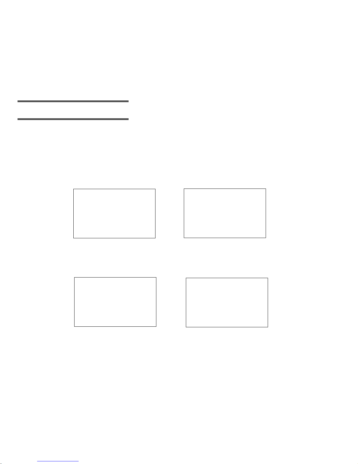
Home Screen
The HOME (Time of Day) screen for the Monitor shows the time in the
upper left-hand corner. Once the Search procedure has been
successfully done, the antenna icon ( ) will show that the Monitor is
getting information from the Transmitter, i.e., telemetry has been
achieved. The antenna icon will stay on the screen as long as there is
telemetry. This screen, as shown to the right, is displayed if no
buttons have been pressed or no alarms/alerts have been triggered.
From any screen, if no buttons are pressed, the Monitor will “time
out” and return to the HOME screen.
12:00 PM
Page 26
20 Chapter 2
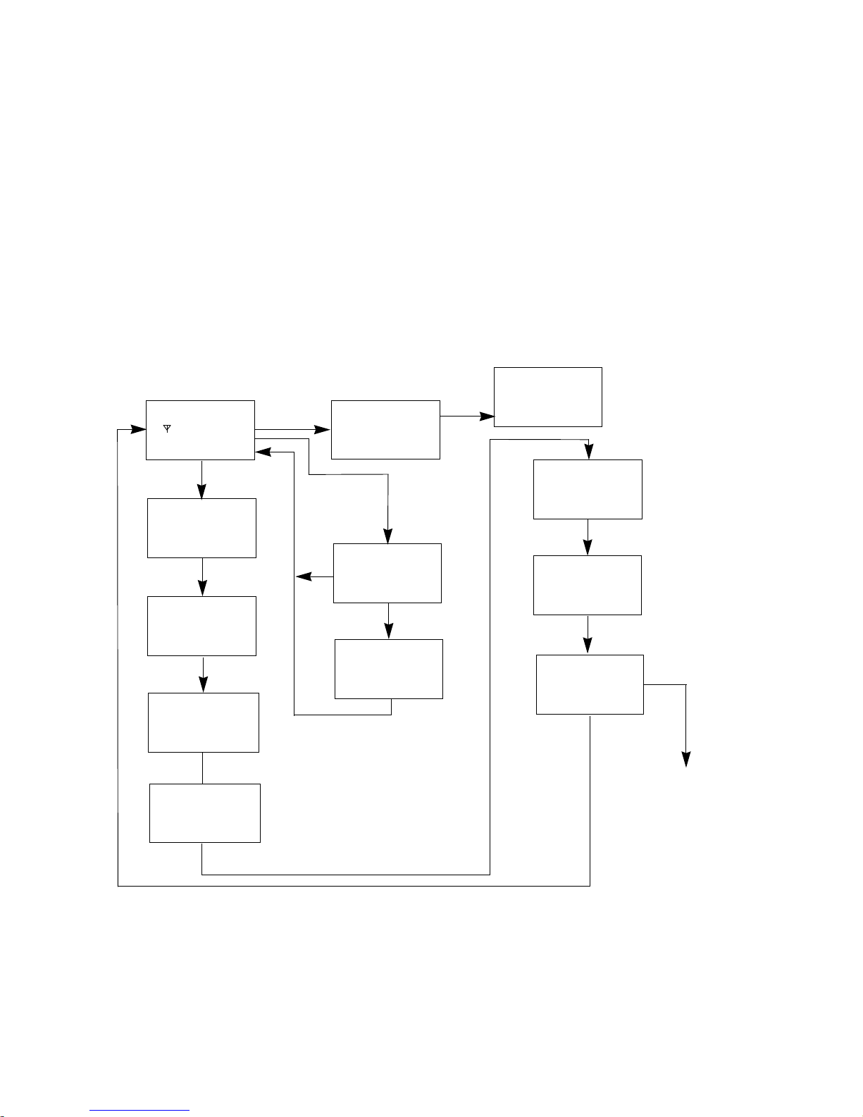
The Main Screens
There are eight main screens in the Guardian RT Monitor: HOME (TIME AND ALARM), GLUCOSE HISTORY,
METER BLOOD GLUCOSE (BG), EVENTS, GLUCOSE ALARMS HISTORY, SEARCH, SIGNALS and SETUP. You can
enter any of these screens from the one before by pressing SEL and then ACT. Figure 2.2 describes the
screen flow. These screens will be explained in detail in Chapter 3: Routine Operati on.
Figure 2.8
SETUP
12: 00
AM
SIGNALS
GLUCOSE
SENSOR
events
GLUCOSE
mg/dl
_ _ _
search
SEL
SEL
SEL
SEL
11:57
PM
CONFIRM
--:--
BG DUE
SNOOZE
11:57
PM
SEL
SET-UP
SUB-SCREENS
UP ARROW
SEL
SEL
ACT
UP ARROW/
SEL
SEL
UP ARROW
POWER
OFF
HOME SCREEN
GLUCOSE
ALARMS
meter bg
mg/dl
_ _ _
SEL
ACT
BLANK SCREEN/
OFF
3:00
PM
NOW
Page 27
Getting Started 21
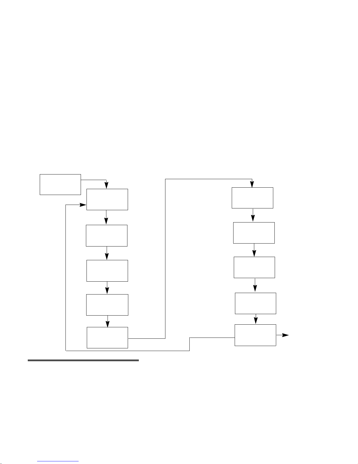
Programming the Monitor
There are ten Setup subscreens in the Guardian RT Monitor: LOW, HIGH, ALERT, SET TIME, DISPLAY, UNIT,
TRANS ID, CLEAR, LANGUAGE, and EXIT. To get to these subscreens: From the HOME Screen (See Figure
2.2) press the SEL button 7 times to reach the SETUP Screen, and press the ACT button to enter. Then
press SEL to scroll through the subscreens and ACT to enter any given one. The subscreens have to be
programmed before starting on the Guardian RT. This process will be explained in the following pages.
Figure 2.3 describes the subscreen flow.
SET-UP SUB-SCREENS
Figure 2.9
NOTE -
Always set time and date before using the Monitor for the first time.
clear
TRANS ID
SET TIME
ALERT
UNIT
SEL
SEL
SEL
SEL
DISPLAY
language
EXIT
SEL
SEL
SEL
ACT
SEL
MAIN MENU
SEL
LIMIT
GLUCOSE
LOW
GLUCOSE LIMIT
HIGH
12:00
AM
12:H r
GLUCOSE
GLUCOSE
SETUP
ACT
mg/dl
mg/dl
mg/dl
_ _ _
_ _ _
HIST:
Page 28

22 Chapter 2
Setting the Language
The Guardian RT offers the choice of displaying Monitor information in seven different languages:
English, French, Spanish, Italian, Swedish, German and Dutch.
From the HOME screen:
1. Press SEL 7 times to get to the SETUP screen.
2. Press ACT once.
3. Press SEL 8 times to get to the LANGUAGE screen.
4. Press ACT. The screen will display the word ENGLISH blinking.
5. Use Up or Down arrow button to scroll through the different languages. Each language will appear
blinking until selected when the ACT button is pressed.
a. With each press of the Up arrow button, this is the language order as it appears on the screen:
English —> French —> Spanish —> Italian —> Swedish —> German —> Dutch
b. With each press of the Down arrow button, this is the language order as it appears on the screen:
English —> Dutch —> German —> Swedish —> Italian —> Spanish —> French
6. Press ACT to choose the desired language.
7. The display will change to the EXIT screen. The screen information will now be shown in the chosen
language.
NOTE -
If when on a language screen SEL is pressed instead of ACT, the display will go to the EXIT
screen, and the language change will not be made.
8. Press ACT to return to the HOME screen.
LANGUAGE
Page 29

Getting Started 23
Setting the Time Display Format
The Monitor gives you a choice of using either 12 or 24-hour time format.
From the HOME screen:
1. Press the SEL button 7 times until the SETUP screen appears.
2. Press the ACT button once to get to the SETUP sub-screens.
3. Press the SEL button 4 times until the DISPLAY sub-screen appears.
4. Press the ACT button once and the upper left-hand corner of the screen will be blinking. The word
SET will appear under the blinking number. Use the Up or Down arrow button to choose either “12”
(AM/PM) or “24” (International) which is the time format to be used.
5. Press the ACT button to set the time format.
6. Press the SEL button and the Monitor will go to the UNIT sub-screen. Press SEL 4 times to go to EXIT.
Press ACT to go back to the HOME screen.
DISPLAY
12:HR
or
DISPLAY
24:Hr
DISPLAY
12:Hr
SET
SET
Page 30
24 Chapter 2
Setting the Time and Date
NOTE -
All steps to set up the Time and Date must be done, or the time and date will not be saved.
NOTE -
If the SEL button is pressed while in a Time/Date subscreen, the display will automatically
change to the Time Display option.
From the HOME screen:
1. Press the SEL button 7 times until the SETUP screen appears.
2. Press the ACT button once to get to the SETUP sub-screens.
3. Press the SEL button 3 times until the SET TIME sub-screen appears.
Setting the Current Hour
1. Press the ACT button once, and the word HOURS will appear. The first two digits will be blinking,
and the word SET will appear.
2. Use the Up or Down arrow button to choose the correct hour. If using the 12-hour format, make sure
the screen shows the correct AM or PM text. For example: AM is displayed and you need PM; press
the Up or Down arrow to scroll through the times until the correct time with PM appears.
3. If using the 24-hour time format, choose hours between “0” and “23.”
4. Press the ACT button once, and the word MINUTES will appear.
or
SET TIME
00:00
SET TIME
12:oo
AM
or
HOURS
00:00
HOURS
12:oo
AM
SET
SET
Page 31

Getting Started 25
Setting the Current Minutes
1. The word MINUTES will now appear with the last two digits of the time blinking.
2. Use the Up or Down arrow button to choose the current minute from “00” to “59.”
3. Press the ACT button once, and the word YEAR will appear.
Setting the Current Year
1. The YEAR will now appear with the number “00” blinking in
the upper right-hand corner of the screen. The starting year is
2000.
2. Use the Up or Down arrow button to choose the last two digits
of the current year. For example: “00” is entered for the year
2000, and “04” is entered for the year 2004, etc.
3. Press the ACT button once, and the word MONTH will appear.
Setting the Current Month
1. The word MONTH will now appear with the number “01”
blinking in the upper right-hand corner of the screen. Use the
Up or Down arrow button to choose the digits for the current
month. For example: “01” is entered for the month of
January, “02” is entered for the month of February, “03” is
entered for the month of March, etc.
2. Press the ACT button once, and the word DAY will appear.
or
MINUTES
00:00
MINUTES
12:oo
AM
SET
SET
YEAR
12:00
SET
AM
00
12:00
SET
AM
MONTH
01
Page 32

26 Chapter 2
Setting the Current Day
1. The word DAY will now appear with the number “01” blinking
in the upper right-hand corner of the screen.
2. Use the Up or Down arrow button to choose the digits for the
current day of the month, from 1 to 31.
3. Press the ACT button once to save date and time values
chosen.
4. The current time and date will appear briefly, and the
Monitor will go to the DISPLAY sub-screen. Press SEL 5 times to go to EXIT. Press ACT once to return
to the HOME screen.
Clearing the Glucose History
NOTE -
If there is data in the Monitor that you want to save, download the data using the Com-
Station and Guardian Solutions Software before clearing the history.
NOTE -
You only need to clear the Monitor glucose history prior to first-time use, between different
users, or at the end of any training or demo sessions prior to first-time use. Glucose history data
in the Monitor overwrites itself automatically, so you do not need to clear the history on a regular
basis.
The Monitor glucose history should be cleared before first-time use. This is to make sure that the
memory is free of unwanted information.
From the HOME screen:
1. Press the SEL button 7 times until the SETUP screen appears.
2. Press the ACT button once to get to the SETUP sub-screens.
12:00
SET
AM
DAY
01
Page 33

Getting Started 27
3. Press the SEL button 7 times until the CLEAR sub-screen appears.
4. Press the ACT button once. The Monitor will beep, and the word NO will appear on the screen
blinking.
5. Use the Up or Down arrow button to choose between YES and NO. Select YES to clear the Monitor
memory.
6. With YES displayed on the screen, press the ACT button once. The Monitor will display YES with
CONFIRM blinking.
GLUCOSE
HIST:
CLEAR
NO
GLUCOSE
HIST:
CLEAR
GLUCOSE
HIST:
CONFIRM
YES
Page 34

28 Chapter 2
7. Press the ACT button again. The Monitor will beep or vibrate and the word CLEARING will appear for
a few seconds.
8. The Monitor will then go to the LANGUAGE screen. The memory will now be cleared. Press SEL to go
to the EXIT screen, followed by ACT to go back to the HOME screen.
9. If NO is selected, the Monitor memory will NOT be cleared, and the Monitor will go to the LANGUAGE
screen. Press SEL to go to the EXIT screen, followed by ACT to go back to the HOME screen.
CLEARING
Page 35

Getting Started 29
Setting the Glucose Unit
The Monitor gives you a choice of entering meter BG values and setting the low blood glucose and high
blood glucose limits in either mg/dl or mmol/l.
From the HOME screen:
1. Press the SEL button 7 times until the SETUP screen appears.
2. Press the ACT button once to go to the SETUP sub-screens.
3. Press the SEL button 5 times until the UNIT sub-screen appears.
4. Press the ACT button once, and use the Up or Down arrow button to choose either mg/dl or mmol/l.
5. Press the ACT button again to save the chosen units, and the Monitor will go to the ID sub-screen.
Press SEL 3 times to go to EXIT, and press ACT one to go back to the HOME screen.
GLUCOSE
UNIT
mg/dl
GLUCOSE
UNIT
mg/dl
SET
Page 36

30 Chapter 2
Setting the Low Glucose Alert
The Monitor is designed to alert the user when the system finds glucose values at or above the set high
glucose limit, or at or below the set low glucose limit. These alerts may be turned off if not needed or
wanted. If an alert is triggered, you should confirm the glucose value with a home glucose meter before
taking any action. Also, you should use a home blood glucose meter to confirm the symptoms of high and
low blood glucose. (See Chapter 1: Introduction for a list of symptoms.)
The low glucose alert can be set from 40-100 mg/dl (2.2-5.5 mmol/l). Enter a glucose value within this
range to set a low glucose alert. Typically , the number entered is above the value that causes you to have
symptoms of low blood glucose. Confirm the alert limit with your doctor.
For this feature to work, you must select ON, a value, and CONFIRM to save the value in memory. Always
treat low blood glucose per the advice of your doctor and the readings of your blood glucose meter.
From the HOME screen:
1. Press the SEL button 7 times until the SETUP screen appears.
2. Press the ACT button once to go to the SETUP sub-screens.
3. The LOW Limit sub-screen will automatically appear with the previously set low-glucose limit (or the
default value of 60 mg/dl (3.3 mmol/l) ) showing in the upper right hand of the display.
4. Press the ACT button and the following screen appears with ON (default setting) blinking:
LOW
LIMIT
GLUCOSE
60
mg/dl
LOW
LIMIT
GLUCOSE
ON
SET
Page 37

Getting Started 31
5. Press the Up or Down arrow button to choose either ON or OFF or rEP (Repeat Function - See Next
Page). If you do not want to use this feature, choose OFF and the low glucose alert feature will be
turned off.
6. Press the ACT button.
7. If ON is entered, the current value will begin blinking.
8. Use the Up or Down arrow button to choose the value you want to set a low glucose alert. Press the
ACT button to save the chosen value. The value 65 mg/dl (3.6 mmol/l) has been entered in this
example.
NOTE -
Since it takes time for the Guardian RT to collect and measure glucose values, there is a
delay in triggering the alert. Ask your doctor which low glucose limit is right for you.
9. Press the ACT button to confirm the chosen value. The screen will go to the HIGH sub-screen. If you
would like, program the HIGH Limit as well. If not, press SEL 8 times to go to EXIT. Press ACT once
to go back to the HOME screen.
10. If you do not want to use this feature, repeat steps 1-4, and then use the Up or Down arrow button
to select OFF and press the ACT button. A CONFIRM screen will be displayed. Press the ACT button
once more to set, and the low glucose alert feature will be turned off.
LOW
LIMITGLUCOSE
60
SET
mg/dl
CONFIRM
65
mg/dl
Page 38

32 Chapter 2
11. To customize the time delay for a specific time period between recurrences of the LOW glucose
alert, repeat steps 1-4. Next, use the Up or Down arrow button to select rEP (blinking), and press
the ACT button.
12. The previously set time interval (or 20 minutes default) will be blinking. Use the Up or Down arrow
button to select the desired interval, in 10-minute increments, from 20 minutes to 60 minutes
(1 hour). Press the ACT button. The CONFIRM screen will be displayed. Press the ACT button to set.
NOTE -
Ask your doctor to which Repeat time interval is right for you.
NOTE -
If after setting a REPEAT interval you change either the REPEAT setting and/or the Low
Alert limit setting, the system will reset, and the Low Glucose Alert will be activated once more.
LOW
LIMIT
GLUCOSE
rEP
SET
CONFIRM
GLUCOSE
SET
00:20
Page 39

Getting Started 33
Setting the High Glucose Alert
The high glucose alert range is 105-400 mg/dl (5.8-22.2 mmol/l). Enter a glucose value within this range
to set a high glucose alert. Typically, the number entered is below the value that causes you to have
symptoms of high blood glucose. Confirm the alert limit with your doctor.
For this feature to work, you must select ON, a value, and CONFIRM to save the value in memory. Always
treat high blood glucose per the advice of your doctor.
From the HOME Screen:
1. Press the SEL button 7 times until the SETUP screen appears.
2. Press the ACT button once to go to the SETUP sub-screens.
3. Press the SEL button once until the HIGH Limit sub-screen appears. The previously set high-glucose
limit (or the default value of 200 mg/dl (11.1 mmol/l)) will appear in the upper right hand of the
display.
4. Press the ACT button and the following screen appears with ON (default setting) blinking:
5. Press the Up or Down arrow to choose either ON or OFF or rEP (Repeat). If you do not want to use
this feature, choose OFF and the high glucose alert feature will be turned off.
HIGH
LIMIT
GLUCOSE
200
mg/dl
HIGH
LIMIT
GLUCOSE
ON
SET
Page 40

34 Chapter 2
6. If ON is activated, the default value will be blinking.
7. Use the Up or Down arrow button to choose the value you want to set a high glucose alert.
8. Press the ACT button to save the chosen value. The following screen will appear with CONFIRM
blinking. The value 240 mg/dl (13.3 mmol/l) has been entered in this example.
NOTE -
Since it takes time for the Guardian RT to collect and measure glucose values, there is a
delay in triggering the alert. Ask your doctor which glucose limit is right for you.
9. Press the ACT button to confirm the chosen value. The screen will go to the ALERT sub-screen. Press
SEL 7 times to go to EXIT. Press ACT once to go back to the HOME screen.
10. If you do not want to use this feature, repeat steps 1-4, and then use the Up or Down arrow button
to select OFF and press the ACT button. A CONFIRM screen will be displayed. Press the ACT button
once more to set, and the high glucose alert feature will be turned off.
HIGH
LIMITGLUCOSE
SET
mg/dl
200
CONFIRM
240
mg/dl
Page 41

Getting Started 35
11. To customize the time delay for a specific time period between recurrences of the HIGH glucose
alert, repeat steps 1-4. Next, use the Up or Down arrow button to select rEP (blinking), and press
the ACT button.
12. The previously set time interval (or 1 hour default) will be blinking. Use the Up or Down arrow to
select the desired interval, in 30-minute increments, from 60 minutes to 180 minutes (3 hours).
Press the ACT button. The CONFIRM screen will be displayed. Press the ACT button to set.
NOTE -
Ask your doctor which Repeat time interval is right for you.
NOTE -
If after setting a REPEAT interval you change either the REPEAT setting and/or the High
Alert limit setting, the system will reset and the High Glucose Alert will be activated once more.
HIGH
LIMIT
GLUCOSE
rEP
SET
CONFIRM
GLUCOSE
SET
1:00
Page 42

36 Chapter 2
Setting the Alert Type
The Set Alert feature gives the choice of BEEP, VIBRATE, or BOTH whenever an alert is triggered. The
default setting for the Monitor is the audible BEEP. Choose the Alert type as follow:
From the HOME screen:
1. Press the SEL button 7 times until the SETUP screen appears.
2. Press the ACT button once to get to the SETUP sub-screens.
3. Press the SEL button 2 times until the ALERT sub-screen appears.
4. Press the ACT button once, and the word BEEP (default setting) will appear blinking. Use the Up or
Down arrow button to choose BEEP, VIBRATE, or BOTH.
5. Press the ACT button again to save your choice in the Monitor memory. If the VIBRATE alert has
been chosen, the Monitor will vibrate briefly and go to the SET TIME and DATE screen.
ALERT
SET
VIBRATE
Page 43

Getting Started 37
6. If you choose the BEEP or BOTH alert, a number 2 (default) will appear blinking above the words
BEEP VOL. You can choose between three different beep volumes: 1 = Low, 2 = Medium, and 3 =
High. Use the Up or Down arrow button to choose 1, 2, or 3. (While scrolling, corresponding beep
tones will sound.)
7. Press the ACT button to save your choice. The Set Time and Date screen will appear. Press SEL 6
times to go to EXIT. Press ACT to go back to the HOME screen.
Entering the Transmitter ID
Each Transmitter is given a unique 7-digit identification number in the factory , from 0000001 to 9999999,
which is the serial number shown on the Transmitter device label. This number (including leading zeros)
must be entered into the Monitor before glucose data sent from the Transmitter can be received and
stored in the Monitor. This will limit the Monitor to only receive data from the Transmitter with that ID
number. If a different Transmitter is used, the new Transm itter ID must be entered.
From the HOME screen:
1. Press the SEL button 7 times until the SETUP screen appears.
2. Press the ACT button once to go to the SETUP sub-screens.
3. Press the SEL button 6 times until the ID sub-screen appears.
4. Press the ACT button, and a 0000000 number will appear with the first digit blinking. Use the Up or
Down arrow button to choose the first digit in your Transmitter ID number.
BEEP VOL
2
TRANS ID
Page 44

38 Chapter 2
5. Press the ACT button again to go to the second digit.
6. The second digit will now be blinking. Use the Up or Down arrow button to choose the second digit in
your Transmitter ID number.
7. Press the ACT button once again to go to the third digit.
8. Keep using the Up or Down arrow to choose numbers for each of the digits left. Then press the ACT
button to go to the next digit. The example below uses 7596.
NOTE -
If the ID number is less than 7 digits, make sure leading zeros are entered.
9. Press the ACT button after the 7th digit has been entered to save the ID in the Monitor. Press SEL
2 times to go to the EXIT screen, followed by ACT to go back to the HOME screen.
SET
0007596
Page 45

Getting Started 39
Inserting the Sensor
Before handling the Sensor, wash hands thoroughly. Choose a site with enough subcutaneous fat for Sensor
insertion. The abdominal area and upper buttocks are the best and most common-used sites for insertion of
the Glucose Sensor. See Figure 2.4 for all body areas where the Glucose Sensor can be inserted.
Figure 2.10
As a rule, AVOID the following areas:
➠ Frequently used injection or pump sites. (Never insert Sensor closer than 3 inches (7.62 cm) from
pump infusion site or manual injection site.)
➠ Belt or waistline
➠ Within 2-inch (5.08 cm) area around navel or less than 3 inches (7.62 cm) from pump infusion site
or manual injection site.)
➠ Site where clothing will rub or press against the Sensor
➠ Scarred or atrophied tissue
➠ Areas experiencing a lot of movement
NOTE -
Clean site with alcohol, making sure site is dry before inserting Sensor. Do NOT use skinprep solutions prior to insertion. However, I.V. Prep may be used after insertion and before
applying a sterile dressing. Lift back of tape slightly to apply I.V. Prep.
CAUTION: Do not connect Sensor to Transmitter at this time.
Page 46

40 Chapter 2
1. Carefully open sterile Sensor pouch, and take out Sensor from package by holding base or tape. Do
not hold Sensor by introducer needle handle. Place the Sensor in the Sen-serter until it fits snugly.
2. Hold Sen-serter as shown:
3. Secure white tape of Sensor, and take off clear tape using counterclockwise motion.
Page 47

Getting Started 41
4. Place fingers on back of white tape, and push carrier down until it clicks in place.
5. As a safety measure, when the Sen-serter is in the loaded position you can set the lock at the top of
the device until you are ready to insert.
a. To Lock: Rotate the white knobs 90o away from the arrows on the side of the Sen-serter.
b. To Unlock: Rotate the white knobs 90o so that they align with the arrows on the side of the
Sen-serter.
Page 48

42 Chapter 2
6. Take off needle guard from introducer needle.
NOTE -
While the use of gloves at this point is required for clinicians, it is optional for patients.
7. Rest Sen-serter legs against skin at 45-degree angle, placing two fingers of opposite hand on Sen-
serter legs to keep this angle.
NOTE -
Sensor may not penetrate skin if insertion angle is less than 45 degrees.
8. Press white button to insert Sensor, checking to see that Sensor is inserted and flush with skin
Page 49

Getting Started 43
9. While holding Sensor in place, gently slide Sen-serter away from Sensor. Do not twist, bend or lift
Sen-serter while taking it off Sensor.
10. Holding Sensor base, take off white paper from adhesive pad. Press adhesive against skin.
11. Hold Sensor with two fingers on base, and gently take out introducer needle at 45-degree angle.
➠ Do NOT rotate introducer needle when taking it out
➠ Throw away needle in sharps container
➠ Check site for redness, bleeding, irritation, pain, tenderness or swelling
NOTE -
The expected life of the Sensor is at least 24 hours and is good for up to 72 hours of use.
Replace Sensor at 72 hours, or earlier in the event of a REPLACE SENSOR (C80) alarm. If these
alarms are triggered, follow instructions in Chapter 4: Troubleshooting and Alarms.
Page 50

44 Chapter 2
Sensor Storage and Handling
➠ Store Sensors in refrigerator at +36° to +50°F (+2° to 10°C). Do not freeze.
➠ Before opening, allow individual Sensor package to reach room temperature and 5% to 95% relative
humidity to avoid condensation.
➠ Sensors taken out of refrigeration must be kept at or below room temperature, +50° to +75°F (+10°
to 24°C), and used within 1 week to ensure Sensor sensitivity.
➠ Throw away Sensor after “Use Before” expiration date on label, or if the package is damaged or the
seal broken.
➠ Do not use Sensor if High temperature-limit indicator is black (not clear).
Sen-serter Maintenance
➠ Occasionally clean Sen-serter with soapy water, using liquid detergent or other household soaps.
Allow to dry.
➠ Disinfect Sen-serter by wiping with 10% bleach solution or 70% isopropyl alcohol as needed.
➠ Always store Sen-serter in the released position to ensure peak product performance and life.
Page 51

Getting Started 45
Affixing the Transmitter
1. Find a comfortable, protected area on the abdomen (away from the belt-line) that is within Cable
reach of the Sensor. Clean the area with isopropyl alcohol and allow to dry.
2. Use the disposable Transmitter adhesive pad (MMT-7006) to affix the Transmitter to your body.
3. Take off the paper backing from the Transmitter side of the adhesive pad (side labeled “1”).
4. Stick the adhesive pad to the smooth, flat, unlabeled side of the Transmitter.
5. Take off the paper from the skin side of the adhesive pad (side labeled “2”). Press firmly to prepped
skin.
6. Transmitter should now be affixed to skin with serial number facing outward.
NOTE -
An adhesive remover, such as Detachol®, can be used to take off the adhesive pad, or any
adhesive residue left on the skin after taking off the pad. Use a product tested for use on skin,
and follow the product’s instructions.
CAUTION: Do not connect Sensor to Transmitter at this time. Do a
SEARCH for the Transmitter first.
Page 52

46 Chapter 2
Searching for the Transmitter
The Search procedure starts communication so that the Monitor can receive and recognize the data
signals from the Transmitter.
NOTE -
Before starting a SEARCH, make sure the Transmitter ID has been entered into the Monitor.
From the HOME screen:
1. Press the SEL button 5 times until the SEARCH screen appears.
2. Press the ACT button and the Monitor will beep or vibrate, and CONFIRM will be blinking on the screen.
3. Press the ACT button again to begin a SEARCH. The screen will display WAITING and a countdown
clock starting at 8 minutes and 00 seconds. The countdown will be in 10-second intervals. Connect
Sensor to Transmitter at start of countdown. It may take up to 8 minutes to finish the SEARCH.
4. If you want to cancel the SEARCH, press SEL. The Monitor will beep or vibrate, and CONFIRM will be
blinking on the screen. Press ACT to confirm.
Caution: Do not press any button on the Monitor while doing a Search. This
interferes with the Search action.
SEARCH
8:00
WAIting
3:58 PM
Page 53

Getting Started 47
Connecting the Sensor to the Transmitter
NOTE -
To extend Transmitter battery life, do not leave Sensor or Test Plug connected to the
Transmitter when system is not in use.
1. With the Monitor in SEARCH mode, hold the base of the Sensor
between the thumb and forefinger so that it doesn’t move. Hold
the Transmitter connector in the other hand. Place the Sensor
connector so that the two connectors are closely aligned. Push
together to connect the Transmitter to the Sensor. You should
hear a click when fully connected.(See Figure 2.5.)
Figure 2.11
2.
The Monitor will search for signals sent by the Transmitter. If the Transmitter is not identified by
the Monitor, an alarm code will appear. See Chapter 4: Troubleshooting and Alarms for detailed
information on Alarm codes.
3. When the Transmitter is identified by the Monitor, the screen will briefly display SUCCESS. The INIT
screen will then appear.
4. Cover the Sensor site with a sterile/snug dressing, such as
IV3000®. (See Figure 2.6.)
Figure 2.12
NOTE -
If the Transmitter is unplugged from the Sensor, wait 20 seconds before reconnecting in
order to ensure normal operation
SUCCESS
3:58
PM
Page 54

48 Chapter 2
Sensor Initialization
After the Transmitter Search is done, the SUCCESS screen will be
briefly displayed. The INIT screen will then appear. The system
automatically initializes the Sensor before starting to record
glucose data. Initialization takes about 120 minutes (2 hours). The
Monitor, however, will count down from 140 minutes (2 hours and
20 minutes) toward 0 hours and 0 minutes, or until finished
(whichever comes first), in one-minute intervals.
Sensor Calibration
When initialization is done, the system will alarm and the Enter
BG screen to the right will be displayed. This screen shows that
calibration is needed. A fingerstick glucose value must be
entered into the Monitor to calibrate the Sensor. The Guardian RT
will not record or display any glucose values, and the High and
Low glucose alerts will not work until calibration is done.
Calibration is needed to make sure the Guardian RT can turn the
electronic signals from the Sensor into glucose values. Make sure
to enter a BG value right after taking a fingerstick glucose reading.
Calibration will happen within 10 to 15 minutes of the Meter BG entry.
NOTE -
Use the same blood glucose meter for all calibrations to ensure the accuracy of the calibrations.
NOTE -
If an incorrect blood glucose value is entered, this value can be overwritten within 10-15
minutes of input.
1. Press the SEL button followed by ACT to clear the alarm.
2. Press the SEL button 2 times. When the METER BG screen appears, the last glucose value (mg/dl or
mmol/l) entered will be displayed. (Dashes will appear the first time since no entry has been made.)
12:00
INIT
AM
2:20
h
12:00
ENTER BG
C 78
AM
---
mg/dl
METER BG
GLUCOSE
Page 55

Getting Started 49
3. Press the ACT button, and the glucose value (dashes) will blink. Use the Up or Down arrow buttons
to scroll through the values until the right one is displayed in increments of 1 mg/dl or 0.1 mmol/l.
Holding down either button will scroll faster through the list of values. The METER BG feature lets you
enter values from 20 to 600 mg/dl (1.1 to 33.1 mmol/l). However, only values between
40-400 mg/dl (2.2-22.2 mmol/l) are used for calibration.
NOTE -
The METER BG screen will display the last value programmed. But when ACT is pressed, the
scrolling will start at “---” and the screen will read ENTER BG. If the Up or Down arrow is
pressed, the next value scrolled to is 100 mg/dl (5.5 mmol/l). If ACT is pressed when “---” is
displayed, no value is entered.
4. Press the ACT button to save the right value. The Monitor will run a calibration and sensitivity check
using the Meter BG value entered and the Sensor value that corresponds in time. Calibration occurs 10
to 15 minutes from the time of entering the fingerstick glucose reading.
5. The HOME screen will appear.
NOTE -
The Monitor will not use values between 20-39 mg/dl (1.1-2.2 mmol/l) and 401-600 mg/dl
(22.2-33.3 mmol/l) for calibration. These values will be displayed and saved for informational
purposes only. BE SURE TO TREAT LOW AND HIGH CONDITIONS PER THE ADVICE OF YOUR
DOCTOR. Also, when a value in the 40-400 mg/dl (2.2-22.2 mmol/l) range is displayed, ENTER BG
will appear below it. When a value in the 20-39 mg/dl (1.1-2.2 mmol/l) or 401-600 mg/dl (22.2-33.3
mmol/l) ranges is displayed, NO CAL will appear below it.
NOTE -
Every time you change your Sensor, a fingerstick glucose reading must be entered into the
METER BG screen. A fingerstick glucose reading should be entered every 6 hours, however, a
minimum of one meter reading must be entered every 12 hours. More frequent daily readings will
optimize the accuracy of the Sensor glucose readings. If you have not entered a reading into the
METER BG screen in 12 hours, a C78 (ENTER BG) alarm will be triggered. This alarm is also
triggered if a calibration has not been done in the last 8 hours since the first calibration.
Page 56

50 Chapter 2
Calibration Pending
If a BG value has been recently entered, but the Up arrow is pressed from the HOME screen within 15
minutes of the entry, not giving the Sensor enough time to calibrate, the screen below will be displayed.
The example 90 mg/dl (5.0 mmol/l) is the recently entered Meter BG value.
No Sync
If the Sensor is not in INIT, (Initialize mode) and still working, and the Guardian RT is not synchronized,
then the screen below will be displayed. This means that the Monitor is not getting Sensor data from the
Transmitter at this point in time.
PENDING
90
mg/dl
GLUCOSE
No SYNC
12:00
AM
Page 57

Getting Started 51
Replacing the Glucose Sensor
If the word REPLACE is displayed on the screen along with a time that is not the current time
(i.e., the time displayed is a future time), the Sensor must be changed before the next calibration is due.
The time displayed is the end of Sensor life. If REPLACE and the current time are displayed on the
screen, then the Sensor is not working and the system is no longer sending Sensor glucose values. Change
out the Sensor immediately to continue using the Guardian RT system.
Removing the Sensor
➠ Remove dressing
➠ Pinch snap arms on sides of Glucose Sensor, and gently disconnect Transmitter Sensor Connector
from Glucose Sensor
➠ Slowly remove Glucose Sensor by pulling it parallel to the skin
➠ Throw away Sensor in Sharps or other biohazard container
NOTE -
To extend Transmitter battery life, do not leave Glucose Sensor connected to the
Transmitter when system is not in use.
REPLACE
12:00
AM
Page 58

52 Chapter 2
Page 59

53
Chapter 3
Routine Operation
This chapter explains how to use the Main Screens of the Guardian RT. From the HOME screen, press the
SEL button to go to each of these operating screens. Press ACT to enter these screens.
NOTE -
Pressing the SEL button from the SETUP screen will take you back to the HOME screen.
Glucose History
The glucose history will display the last 8 hours of glucose values. The oldest value will be displayed if
the Up arrow button is pressed, or the newest (most recent) if the Down arrow button is pressed, for a
total of 96 available entries. The history can be viewed in 5- or 30-minute increments. From the HOME
Screen:
1. Press the SEL button once until the GLUCOSE HISTORY screen appears. In the example below, the
most current glucose value is 108 mg/dl (6.0 mmol/l).
NOTE -
The word NOW on the screen above refers to the current Sensor glucose value.
NOW
GLUCOSE
11:57
PM
108
mg/dl
Page 60

54 Chapter 3
2. Scroll through the history by using the Up arrow button to go from oldest to newest glucose value in 5-minute
increments. Press the Down arrow button to go from newest to oldest glucose value in 5-minute increments. In
the example below, the glucose value was 112 mg/dl (6.22 mmol/l), 5 hours and 25 minutes ago.
3. If the ACT button is pressed, the scrolling display will switch from 5- to 30-minute increments, and an
asterisk ( ) will be displayed next to the time increment. If you now press the Up arrow button, the
history will go from oldest to newest glucose value in 30-minute increments. If you press the Down arrow
button, the history will go from newest to oldest glucose value in 30-minute increments. In the example
below, the glucose value was 96 mg/dl (5.33 mmol/l) 4 hours and 35 minutes ago. Press the ACT button to
go back to scrolling in 5-minute increments. The asterisk will no longer be displayed.
4. If the glucose value is lower or higher than operational range of 40-400 mg/dl (2.2 -22.2 mmol/l),
the screen will display LO or HI where the glucose value is normally found. See example below.
NOTE -
When there is no calibration for the Sensor value, NO CAL* will be displayed on the bottom
of the screen in place of NOW. In these cases,
“---”
will be displayed for the glucose value.
When the Sensor value is unstable, NOISE* will be displayed on the screen. And when the Sensor
value is unavailable due to bad or no telemetry, MISSED* will be displayed on the screen.
-5h 25M
GLUCOSE
HIST:
11:57
PM
112
mg/dl
X
-4H 35M
X
GLUCOSE
HIST:
11:57
PM
96
mg/dl
-5H 25M
GLUCOSE
HIST:
mg/dl
LO
11:57
PM
Page 61

Routine Operation 55
Entering Meter BG for Calibration
In order for the electronic signals from the Sensor to be converted into glucose values, Meter BG (Blood
Glucose) readings must be entered into the Guardian RT for the purpose of calibration. See Chapter 2:
Getting Started, Sensor Calibration.
From the HOME screen:
1. Press the SEL button 2 times and the METER BG screen will appear. In the example below, the last
entered meter blood glucose value was 95 mg/dl (5.3 mmol/l). This value will thus appear on the
display. (If no BG reading was entered before, dashes (“- - -”) will appear on the screen.)
2. Press the ACT button, and the number display will go to dashes. Enter the desired meter blood
glucose value, in increments of 1 mg/dl (0.1 mmol/l), by using the UP or Down arrow button.
Remember, the number value will start at 100 mg/dl. See Chapter 2: Getting Started, Sensor
Calibration.
NOTE -
If you scroll below 40 mg/dl (2.22 mmol/l) or above 400 mg/dl (22.2 mmol/l) the screen will
display “NO CAL.” The value entered will be stored but not used for calibration.
3. Press the ACT button to set the value, and the display will return to the HOME screen.
MEter BG
95
mg/dl
12:00
AM
ENter BG
mg/dl
---
SET
Page 62

56 Chapter 3
BG Due
One useful feature of the Guardian RT is the BG DUE screen. This screen lets you know when to enter the
next needed blood glucose (BG) value into the Guardian RT to go on with calibration.
From the HOME screen:
1. Press the Up arrow button once. If an initial Sensor calibration has already been performed, the
screen will display when the next BG entry is due. Pressing SEL or ACT once, or the Up arrow 2
times, will return you to the HOME screen. In the example below, the last calibration was done at
12:45 A.M. Therefore, the next BG value is due before 12:45 P.M. because the last BG entered was
12 hours before.
Depending on the condition and calibration status of the Sensor, there are four other screens that may be
displayed, instead of BG DUE, by pressing the Up arrow once from the HOME screen. These screens are:
ENTER BG, PENDING, NO SYNC, and REPLACE.
NOTE -
If calibration is pending, do not turn off the Monitor. Otherwise, you will have to enter a new
Meter BG value.
BG DUE
12:45
PM
Page 63

Routine Operation 57
Enter BG
If no calibration has been done, and no calibration is pending, the screen below will be displayed if the
Up arrow is pressed from the HOME screen.
Calibration Pending
If a BG value has been recently entered, but the Up arrow is pressed within 15 minutes of the entry, not
giving the Sensor enough time to calibrate, the screen below will be displayed. The example 90 mg/dl
(5.0 mmol/l) is the recently entered Meter BG value.
ENTEr bg
12:45
PM
PENDING
90
mg/dl
GLUCOSE
Page 64

58 Chapter 3
No Sync
If the Sensor is not in INIT (Initialize mode), and still working, and the Guardian RT is not synchronized,
then the screen below will be displayed. This means that the Monitor is not getting Sensor data from the
Transmitter at this point in time.
Replacing the Glucose Sensor
If the word REPLACE is displayed on the screen along with a time that is not the current time
(i.e., the time displayed is a future time), the Sensor must be changed before the next calibration is due.
The time displayed is the end of Sensor life. If REPLACE and the current time are displayed on the
screen, then the Sensor is not working and the system is no longer sending Sensor glucose values. Change
out the Sensor immediately to continue using the Guardian RT system.
No SYNC
12:00
AM
REPLACE
12:00
AM
Page 65

Routine Operation 59
Events
The EVENT screens are used to record information that might affect glucose values. Events are stored
but they cannot be reviewed on the Monitor display (except previously entered values). Event markers
and related values can be downloaded, along with the glucose Sensor history, to the Guardian Solutions
Software using the Com-Station cradle. Event information is helpful in evaluating glucose trends and
patterns displayed in the software reports. There are four types of events that can be recorded into the
Monitor:
‡ Insulin
‡ Carb Amount
‡ Exercise
‡ Other
From the HOME screen:
1. Press the SEL button 3 times, and the EVENTS screen will appear.
2. From the EVENTS screen, press the ACT button. The screen will display INSULIN, and it will be
blinking. Use the Up arrow to move between the following Event options:
‡ Insulin
‡ Carb Amount
‡ Exercise
‡ Other
EVENTS
Page 66

60 Chapter 3
Units of Insulin Taken
From the HOME screen:
1. Press the SEL button 3 times, and the EVENTS screen will appear.
2. Press the ACT button once, and the screen will display SET and INSULIN will be blinking. (Dashes will
be displayed if no insulin amount was entered before.)
NOTE -
If you are an insulin pump user, the dose refers to your bolus, not basal insulin. If your bolus
amounts are in the hundredth of a unit (2 places after the decimal point), round to the nearest
tenth of a unit (one place after the decimal point) or whole number of units.
3. Press the ACT button.
4. Press the Up or Down arrow button to enter units of insulin taken, from 0.1 to 99 units.
5. Press the ACT button to confirm, and a blinking CARB AMT screen will appear.
INSULIN
7.0
U
SET
Page 67

Routine Operation 61
Carbohydrate Amount
After an Insulin dose has been entered and the ACT button pressed, the screen will display SET, and CARB
AMT will be blinking. (Dashes will be displayed if no carb amount was entered before.) If you do not want
to enter a carbohydrate amount, press SEL until the HOME screen appears. Otherwise, follow these
steps.
1. Press the ACT button.
2. Press the Up or Down arrow button to enter the amount of carbohydrate eaten. (Example: One
baked (6 ounce) potato is 30 grams of carbohydrate.) The unit range is from 1 to 300. Enter the Carb
Amount in units, grams, or exchanges. If you do not know how to figure out amount of carbohydrate
eaten, ask your doctor to learn how.
3. Press the ACT button again to save the carbohydrate amount in the Monitor memory. Return to the
HOME screen.
Duration of Exercise
From the HOME screen:
1. Press the SEL button 3 times, and the EVENTS screen will appear.
2. Press the ACT button once. The screen will display SET, and INSULIN will be blinking.
3. Use the Up or Down arrow button to choose the exercise Event option. The screen will display SET,
and EXERCISE will be blinking. (Dashes will be displayed if no exercise amount was entered before.)
50
CARB AMT
SET
Page 68

62 Chapter 3
4. Press the ACT button. Use the Up or Down arrow buttons to enter how long you have exercised. You
can enter Exercise in 10-minute increments up to 4 hours.
5. Press the ACT button to save the exercise length and go back to the HOME screen.
Other Events
Any other important events, such as illness, menstrual cycle, etc., can be entered using the OTHER
screen.
From the HOME screen:
1. Press the SEL button 3 times, and the EVENTS screen will appear.
2. Press the ACT button once. The screen will display SET with “INSULIN” blinking.
3. Press the Down arrow, and the screen will display SET, and “OTHER” will be blinking.
4. Press the ACT button again to enter the OTHER event and go back to the HOME screen.
NOTE -
No values are associated with OTHER events. Track the type of event manually in your
logbook.
0:30
EXERCISE
SET
H
SET
OTHER
Page 69

Routine Operation 63
Glucose Alarm History
The glucose alarm history will display the last 20 high and low glucose alarms received.
From the HOME Screen:
1. Press the SEL button 4 times until the GLUCOSE ALARMS screen appears.
2. Press the ACT button to view the saved alarms.
3. If there are no alarms in the history, the following screen will appear:
4. If there are alarms in the history, the newest one will be displayed first. The alarm will be displayed
with the time and date they were triggered and the corresponding value.
5. In the example below, an alarm was triggered at 13:04 (1:04 PM) on August 3, 2002 when the glucose
value reached 140 mg/dl (7.77 mmol/l). This value is at or above the High glucose limit setting.
ALARMS
GLUCOSE
NONE
- -: - -
140
13:04
03AUG02
GLUCOSE
mg/dl
Page 70

64 Chapter 3
6. If the glucose value was outside the “operational range” of 40-400 mg/dl (2.2 -22.2 mmol/l), then
the Guardian RT will display either of these two screens:
7. Use the Up or Down arrow button to go through the rest of the Glucose Alarm History. Pressing the
DOWN arrow will display the previous (next-most recent) alarm. Pressing the UP arrow will display
the oldest alarm. Press SEL to return to the HOME screen.
13:04
GLUCOSE
LO
03AUG02
13:04
GLUCOSE
HI
03AUG02
Page 71

Routine Operation 65
Search
The Search procedure start synchronized communication between the Monitor and the Transmitter. The
Search procedure is explained in detail in Chapter 2: Getting Started, Searching for the Transmitter.
Please refer to that section for more information.
Signals
The SIGNALS screen is useful to make sure the ISIG (Input Signal, i.e., Sensor signal) readings are in the
correct range. Reviewing the Signal readings is valuable for reporting Signals within an acceptable range
and when doing the Test Plug Procedure (See Chapter 4: Troubleshooting and Alarms). This procedure
lets you know if the Monitor, Transmitter or Sensor are working properly.
From the TIME AND ALARM Screen:
1. Press the SEL button 6 times until the SIGNALS screen appears. Press the ACT button to view the
ISIG. Press the ACT button once more and the SETUP screen will be displayed.
2. If the Up or Down arrow button is pressed from the ISIG screen, the VCTR (Sensor voltage) screen is
displayed. This screen is for diagnostic purposes only and not for everyday use.
NOTE -
When in the INIT (Initialization) mode, do not go to the signals screen until the Monitor has
counted down to between 133 and 130.
SEARCH
Signals
GLUCOSE
Page 72

66 Chapter 3
NOTE -
While unlikely, moisture may enter the Guardian RT Transmitter connector during normal use.
This may lead to erratic ISIG values above 200 nA. Stop Sensor use if problems with moisture are
suspected. Remove the Transmitter from the skin surface and allow to air dry for 3-4 hours.
(More or less drying time may be needed, depending on the air temperature and humidity.) Once
dry, perform the Test Plug Procedure. If the ISIG values are in the range of 24-29 nA, then the
Transmitter is working correctly.
The Snooze Option
The Guardian RT has a Snooze option that works with the HIGH alert feature. This option can be turned
on during a specific period of time when you are expecting your glucose level to rise above the set HIGH
limit (e.g., after eating a heavy meal). It can also be set if you do not want the HIGH alert to interrupt
you during a given time interval (e.g., during a business meeting). The Snooze option will thus deactivate
the HIGH alert for a specified period, from 1 to 12 hours.
In order to get to, and set, this feature, the Glucose HIGH limit setting must be ON. At the end of the set
SNOOZE time period, the high glucose alarm feature will be turned on once more. You can view the
SNOOZE screen to see how much of the set SNOOZE time is remaining. To turn the SNOOZE feature OFF at
any time, access the SNOOZE screen, select --:-- and press the ACT button.
From the HOME screen:
1. Press the Up arrow 2 times to reach the SNOOZE screen.
2. Press the ACT button to display the time interval (blinking dashes).
3. Use the Up or Down arrows to choose the desired interval. Press the ACT button to set and go back
to the HOME screen.
4. The HOME screen will now display “S” in the upper right corner.
NOTE -
Ask your doctor if the Snooze option is right for you, and if so, what your personal Snooze
setting should be.
Snooze
SET
--:--
Page 73

67
Chapter 4
Troubleshooting and Alarms
This chapter lists the Monitor alarms and how to troubleshoot and respond to them to keep the system
working smoothly. If an alarm is triggered, the Monitor will beep, vibrate, or do both, depending on the Alert
setting. All alarms are cleared by pressing the SEL button, followed by the ACT button. If an alarm is not
cleared within 10 minutes, a continuous tone will sound.
Alarms with the letter “F” on the display are system errors. Before clearing these types of alarms, U.S. and
Canadian customers, please contact the Product Help Line at 800-MINIMED (800-646-4633) or 818-576-5555.
All other international customers please contact your local sales office.
If more than one alarm has been triggered, the alarms will be shown in order on the display, starting with
the oldest. The alarm type and when it was triggered is stored in the Monitor memory for later download to
the Guardian Solutions Software.
NOTE -
Always take care of alarms right away. The first button press after an alarm is triggered
turns on the display backlight. The backlight will stay on for about 10 to 20 seconds after the last
button press.
NOTE -
A calibration must be done after taking care of certain alarms by entering a new METER BG
value. No Monitor glucose values will be reported after these alarms are triggered until a
successful calibration is done.
NOTE -
If a key is pressed and held down at the same time that an alarm is triggered, the alarm will
not be displayed until the key is released.
CAUTION: An audible alarm may not awaken you if you are a heavy sleeper, or if
the sleeping environment has a significant amount of background noise.
If there is a chance of not being awakened by the BEEP alert mode, then
you should either use the VIBRATE or the BOTH mode. You should
confirm that the alarm volume will be adequate to awaken you if an
alarm is triggered during sleep.
Page 74

68 Chapter 4
List of Alarms
No ID
Error Message: C52/NO ID (Missing Transmitter ID)
Cause: A Transmitter ID has not been entered in the Monitor.
Action: Press the SEL button and then the ACT button to clear the alarm. Enter the Transmitter ID (serial
number) into the Monitor’ s TRANS ID setup screen. See Chapter 2: Getting Started.
NO ID
12:00
AM
C52
Page 75

Troubleshooting and Alarms 69
High
NOTE -
If the alert pattern is set on beep, a series of ascending tones will be heard. This tone is
unique to the HIGH alert. If the alert type is set on vibrate, vibrations do not vary for different
alarms.
NOTE -
In the screen above, 250 mg/dl is being used as an example.
Error Message: HIGH (High Glucose Alarm)
Cause: Glucose value is higher than or equal to the high glucose limit.
Action:
5. Press the SEL button and then the ACT button to clear the alarm. The alarm will turn off and the
HOME screen will reappear. The alarm will repeat about every hour (or longer if the Repeat interval
has been customized) until the condition has been corrected.
6. Take a blood glucose meter reading. If the value indicates a high blood glucose level, treat per your
doctor’s instructions and enter the value into the Monitor for calibration.
7. Even if the blood glucose value does not confirm the alarm, enter the value into the Monitor for
calibration.
HIGH
12:00
AM
GLUCOSE
mg/dl
250
Page 76

70 Chapter 4
Low
NOTE -
If the alert pattern is set on beep, a series of descending tones will be heard. This tone is
unique to the LOW alert. If the alert type is set on vibrate, there is no differentiation between
the vibrations for the different alarms.
NOTE -
In the screen above, 60 mg/dl is being used as an example.
Error Message: LOW (Low Glucose Alarm)
Cause: Glucose value is lower than or equal to the low glucose limit set.
Action:
1. Press the SEL button and then the ACT button to clear the alarm. The alarm will turn off and the
HOME screen will reappear. The alarm will repeat about every 20 minutes (or longer if the Repeat
interval has been customized) until the condition has been corrected.
2. Take a blood glucose meter reading. If the value indicates low blood glucose level, treat per your
doctor’s instructions and enter the value into the Monitor for calibration.
3. Even if the blood glucose reading does not confirm the alarm, enter the value into the Monitor for
calibration.
LOW
12:00
AM
mg/dl
GLUCOSE
60
Page 77

Troubleshooting and Alarms 71
Check Sensor
Error Message: C54/CHECK
Cause: The Monitor picked up a Sensor current that is outside the operating range or is unstable.
Action:
1. Press the SEL button and then the ACT button to clear the alarm. The alarm will turn off, and the
HOME screen will reappear. The alarm will repeat periodically until the condition is corrected.
2. Make sure the insertion site appears normal and the Sensor is still connected. DO NOT REMOVE
CONNECTOR.
3. If the alarm is triggered two or more times, take out the Sensor. Before putting in a new Sensor, do
the Test Plug procedure at the end of this chapter to check system function.
4. If the Transmitter is not working correctly, a new Transmitter must be used. If it is working
correctly, put in a new Sensor. Run initialization and calibration. See Chapter 2: Getting Started.
check
12:00
AM
C54
GLUCOSE
SENSOR
Page 78

72 Chapter 4
Low Batt
Error Message: LOW BATT (Low Batteries)
Cause: The voltage of the AAA batteries in the Monitor is low.
Action: Press the SEL button and then the ACT button to take care of the alarm. When this alarm is first
triggered, the batteries have about eight hours of normal operating life left. The time of the first alarm
is recorded into the Monitor memory. The Battery icon will be displayed on the HOME screen.
1. Turn Off the Monitor.
2. Change the batteries. See Chapter 2: Getting Started.
NOTE -
Make sure to put in new batteries within 10 minutes of taking out the old ones to avoid
automatic resetting of date and time. This will also avoid the triggering of a Replace Sensor alarm.
3. Do a manual Search procedure:
a. From the HOME Screen, press the SEL button 5 times until the SEARCH screen appears.
b. Press the ACT button and the Monitor will beep or vibrate. CONFIRM will be blinking on the
screen.
c. Press the ACT button again to begin a SEARCH. The screen will display SEARCH and the number 8
(minutes). A countdown will begin. It may take up to 8 minutes to finish the SEARCH.
NOTE -
Frequent use of the backlight and having the alert type on “vibrate” will use up batteries
quicker.
12:00
AM
LOW BATT
-
+
Page 79

Troubleshooting and Alarms 73
Off/No Power
Error Message: OFF/NO POWER (Replace Batteries)
Cause: There is less than one (1) hour of battery life left. The Monitor will turn off.
Action:
1. Press the SEL button and then the ACT button to CLEAR the alarm.
2. CHANGE THE BATTERIES RIGHT AWAY TO AVOID LOSS OF DATA STORED IN MEMORY! Follow steps
in Chapter 2: Getting Started.
3. Perform the manual Search procedure:
a. From the HOME Screen, press the SEL button 5 times until the SEARCH screen appears.
b. Press the ACT button and the Monitor will beep or vibrate. CONFIRM will be blinking on the
screen.
c. Press the ACT button again to begin a SEARCH. The screen will display SEARCH and the number 8
(minutes). A countdown will begin. It may take up to 8 minutes to finish the SEARCH.
12:00
AM
NO POWER
-
+
OFF
Page 80

74 Chapter 4
Service C60/61
Error Message: C60/SERVICE (Transmitter Battery Low/End of Battery Life)
Cause: The Transmitter battery is low when C60 appears. The C60 service alarm will repeat each day
around 12:00 noon. Service C61 means that the Transmitter battery is used up.
Action: Press the SEL button and then the ACT button to clear the alarm. The battery cannot be changed in the
Transmitter . The battery life is about one year. Change out the Transmitter as soon as possible. Take off
the Sensor, and insert a new Sensor to connect to the new T ransmitter. After the T ransmitter is changed,
the Monitor must be reprogrammed with the new Transmitter ID number . See Chapter 2: Getting
Started.
Re Init
Error Message: C62/RE INIT (Re-Initialize Sensor)
Cause: The Monitor did not get the needed setup information from the Transmitter.
Action: Press the SEL button and then the ACT button to clear the alarm. Disconnect the Sensor from the
Transmitter . Perform Search, reconnect Sensor , and following Initialization, enter blood glucose
calibration. See Chapter 2: Getting Started.
NOTE -
If this alarm is triggered repeatedly, change out Sensor and do Initialization process once more.
SERvice
12:00
AM
C60
re init
12:00
AM
C62
Page 81

Troubleshooting and Alarms 75
No Sync
Error Message: C76/NO SYNC (Loss of Communication)
Cause: The Monitor and Transmitter are out of synchronization. As a result, the Monitor is unable to get
data from Transmitter. The search for the Transmitter has failed, or communication has been
lost.
Action:
1. Press the SEL button and then the ACT button to clear alarm. If Transmitter Search is not done, the
alarm will repeat every 20 minutes.
2. Make sure that the Transmitter ID entered correctly (including leading zeros). If it is, do a manual
SEARCH procedure:
a. From the HOME Screen, press the SEL button 5 times until the SEARCH screen appears.
b. Press the ACT button and the Monitor will beep or vibrate. CONFIRM will be blinking on the
screen.
c. Press the ACT button again to start a SEARCH. The screen will display SEARCH and the number 8.
A countdown will begin. It may take up to 8 minutes to finish the SEARCH.
3. If not correct, reenter the Transmitter ID number and do the Sensor Initialization procedure. See
Chapter 2: Getting Started.
4. Reposition the Monitor and Transmitter within 5-10 inches (12.7-25.4 cm) of each other and retry
the SEARCH procedure.
5. Is a cell phone or another RF transmitter working nearby? If so, move further away, and retry the
manual SEARCH procedure.
6. Wireless transmission between the Monitor and the Transmitter within the six-feet operating range
may be interrupted due to Transmitter Cable orientation. Move the Monitor closer to the
Transmitter or to another position and retry the SEARCH procedure.
NO sync
12:00
AM
C76
Page 82

76 Chapter 4
7. If alarm continues, U.S. and Canadian customers please contact the Product Help Line at 800-MINIMED
(800-646-4633) or 818-576-5555. All other international customers please contact your local sales
office.
Cal Err
Error Message: CAL ERR (Calibration Error)
Cause: Calibration cannot be done successfully due to Monitor and Transmitter not communicating,
Meter BG outside expected range from Sensor reading, or Monitor was turned off for more than
2 hours.
Action:
1. Press the SEL button and then the ACT button to clear the alarm. The alarm will turn off, and the
HOME screen will appear. An alarm to recalibrate will repeat until a new calibration is
done.
2. Check to make sure that the antenna icon is displayed. If it is not displayed, the communication link
between the Transmitter and the Monitor has not been set. Restore communication between the
Transmitter and the Monitor. Make sure the Monitor and Transmitter are within 6 feet (2 meters) of
each other.
3. Take fingerstick reading and enter meter BG value, between 40-400 mg/dl (2.2-22.2 mmol/l), for
calibration.
CAL ERR
12:00
AM
Page 83

Troubleshooting and Alarms 77
Key Held
Error Message: C77/KEY HELD
Cause: A Monitor key has been pressed and held for more than 3 minutes.
Action: Press the SEL button and then the ACT button to clear the alarm.
Enter BG
Error Message: C78/ENTER BG (Enter Calibration Value)
Cause: Calibration is needed. No new glucose values will be recorded until calibration is done.
Calibration value must be between 40-400 mg/dl (2.22-22.2 mmol/l). This alarm is triggered if
calibration has not been done in the last 12 hours or following a CAL ERR alarm, or if a
calibration has not been done in the last 8 hours since the first calibration.
Action: Press the SEL button and then the ACT button to clear the alarm. Take a fingerstick reading using a
meter. Press the SEL button until the METER BG screen appears. Press the ACT button, and the dashes “-
--” will blink. Press the Up or Down arrow button to scroll through the values until meter value is
displayed. Press the ACT button to confirm. Until calibration is done, this alarm will repeat hourly.
Key HELD
12:00
AM
C77
ENTER BG
12:00
AM
C78
Page 84

78 Chapter 4
Set Time
Error Message: C79/SET TIME (Reset Date and Time in Monitor)
Cause: The internal clock has cleared. Most likely the batteries were taken out and not placed back for
more than 10 minutes, and the clock does not have the right time.
Action: Press the SEL button and then the ACT button to take care of the alarm. Reprogram your Monitor, and
change Sensor, if prompted, following the instructions in Chapter 2: Getting Started.
SET TIME
12:00
AM
C79
Page 85

Troubleshooting and Alarms 79
Replace Sensor
Error Message: C80/REPLACE (Change Sensor/End of Sensor Life)
Cause: The maximum expected life of the Sensor has been reached. In other words, either the Monitor
has seen a problem with the Sensor, triggering two calibration alarms, one after the other, or 72
hours have passed since the Sensor was first put in and initialized. This alarm will repeat every
20 minutes until the Sensor is changed and initialized.
Action:
1. Press the SEL and then the ACT button to turn off the alarm.
2. Turn the Monitor Off.
3. Turn the Monitor On.
4. Remove the Sensor, and insert a new Sensor. Follow the Inserting the Sensor section in Chapter 2:
Getting Started. Initialize the Sensor by following the Sensor Initialization section also in Chapter 2.
NOTE -
If after changing the Sensor, but before doing the initialization, the alarm repeats, turn off
the alarm and go on with initialization.
GLUCOSE
REPLACE
SENSOR
12:00
C80
AM
Page 86

80 Chapter 4
System Alarms
These alarms are triggered when a diagnostic test finds an error in the Monitor. If an alarm code has an
“F” followed by two numbers (example shown below), do the following procedure:
1. Write down the alarm code.
2. Download data into a personal computer right away (using the Com-Station and Guardian Solutions
Software) to help with troubleshooting the device.
3. To report the alarm, U.S. and Canadian customers please contact the Product Help Line at 800-MINIMED
(800-646-4633) or 818-576-5555. All other international customers please contact your local sales
office.
4. Clear the alarm by pressing the SEL button and the ACT button. The Monitor programming will
change to factory settings, except for glucose history data. All other information needs to be
reprogrammed after speaking with the Product Help Line.
Service
12:00
AM
F##
Page 87

Troubleshooting and Alarms 81
Test Plug Procedure
If you come across an operating problem, the Test Plug gives information that can let you know if a
Sensor, Monitor or Transmitter is working correctly. The Test Plug sends a constant electronic signal to
the Monitor. This data can be read on the Monitor Signals screen. The normal signal range is about
24-29 nA (nanoamperes).
1. Disconnect the Sensor from the Transmitter’s Sensor connector.
2. Press the SEL button until the SEARCH screen appears, and start the search for the Transmitter. See
Chapter 2: Getting Started.
3. Connect the Sensor Connector end of the Transmitter to the Transmitter Connector end of the Test
plug (see Figure 4.1). Press the parts together until the snap arms on the Cable Connector come
together with a click.
Figure 4.1
4.
If the Monitor recognizes the Transmitter, the Monitor will enter the Initialization mode. The
Monitor will display INIT and 2:20 h.
5. The Monitor will count the minutes down from 2:20 h. Data is first sent in the 2:13 to 2:10 h. To
check the correct ISIG values (ISIG stands for Input Signal, which is the Sensor current) you must
wait for data to be first sent. Let the Monitor reach this range in time; it will take between seven to
ten minutes. This wait period ensures that the reading from the Transmitter is stable.
Sensor
Connector
Transmitter
Connector
Page 88

82 Chapter 4
6. When the Monitor displays between 2:13 and 2:10 h, go to the SIGNALS screen (From the HOME
screen, press SEL 6 times and then press ACT) to view the ISIG.
NOTE -
Do not go to the signals screen until the Monitor has counted down to between 2:13 and 2:10 h.
7. If the ISIG value is between 24 and 29 nA, and the Initialization screen shows 2:00 h or less, the
Transmitter and Monitor are working properly. Change the Sensor. Initialize and calibrate the new
Sensor. Refer to Chapter 2: Getting Started.
NOTE -
If you miss the first transmission of data and the second transmission has been sent, the
ISIG reading will typically be above 29 to 34 nA and can go very high. This value should be
ignored. All following transmissions will return to the 24-to-29 nA range.
8. If the ISIG value is outside the range of 24 to 29 nA, the Transmitter, Monitor, or both, may have a
problem. U.S. and Canadian customers, please contact the Product Help Line at 800-MINIMED
(800-646-4633) or 818-576-5555. All other international customers please contact your local sales
office.
NOTE -
To extend the operational life of the Transmitter battery, do not leave the Test Plug
connected to the Transmitter when not in use.
Signals
GLUCOSE
SENSOR
Page 89

Performance Characteristics 83
Chapter 5
Performance Characteristics
NOTE -
Users should have the information in this chapter reviewed by their healthcare provider.
The Medtronic MiniMed Guardian RT uses a glucose Sensor to continuously monitor your glucose levels.
The Guardian RT Sensor is “calibrated” using your home blood glucose meter. Once calibrated, the
Guardian RT reports glucose values every 5 minutes. These values were compared to reference
laboratory blood glucose measurements to check the Guardian RT’s performance characteristics in a
clinical study1.
Although presentations to characterize performance of the Guardian RT are given below, there is no
commonly accepted statistical approach for capturing the performance of continuous glucose monitors
such as the Guardian RT. Performance may be best characterized by viewing graphs called time-elapsed
plots. In these plots, the values from Guardian RT for one subject over time are overlaid with values at
the same time from the glucose reference method. Three representative time-elapsed plots of Sensors
that exhibited excellent performance, average performance and poor performance are shown on pp. 9597 (Figures 5.3-5.5).
1
Medtronic MiniMed, A Frequent Sample Accuracy Evaluation of the Medtronic MiniMed T elemetered Glucose Monitoring System
II (TGMS II) in Subjects with Type 1 Diabetes Mellitus, August 2004.
Page 90

84 Chapter 5
Performance Results
The performance of the Guardian RT was evaluated in a clinical study. Guardian RT results were compared to
plasma glucose values from a reference method, the YSI 2300 STAT PlusTM glucose analyzer (referred to as
YSI). Sixteen subjects with Type I diabetes participated in a single-site in-clinic study. Subjects ranged in age
from 18 to 65 years old. Each subject wore 2 Guardian RT systems simultaneously. One Guardian system was
calibrated an average of 3.5 times per day, and the other was calibrated approximately 5 times per day using
the BD LogicTM meter. YSI measurements were taken every thirty minutes.
Users and their healthcare providers should consider that performance in this study may be idealized, and
that performance may be worse when the Guardian RT is used in a less-controlled home setting. For
example:
‡ The mean Hemoglobin A1c among the 16 participants was 8.2%. As hemoglobin A1c levels rise,
conditions often occur which are most challenging to test systems measuring glucose in interstitial
fluid, i.e., higher glucose levels, more rapid changes in glucose concentrations, and often more
hypoglycemic episodes.
‡ Subjects saw, on average, between 4 and 5 fingerstick values per day. This enables subjects to
better manage their diabetes when compared to those who perform less fingersticks per day.
Agreement between Guardian RT and YSI values is shown to be closer at mid-range glucose levels,
as compared to agreement at low or high glucose concentrations.
‡ Subjects were more limited in their activities than what may exist in home use, and they were
provided with all their meals. Sensors were also inserted by clinic staff rather than the subjects
themselves. Subjects who are more active, or with poor eating habits, may create more challenging
conditions for the Guardian RT.
‡ Performance of the Guardian RT may vary depending on the glucose meter used and how well the
meter is maintained. It is important to carry out quality-control checks on the meter and code the
meter according to the manufacturer's instructions to optimize performance of the Guardian RT.
Page 91

Performance Characteristics 85
Accuracy of Guardian RT Readings
In this study, YSI measurements (taken every half hour) were paired with the corresponding Guardian RT
reading (taken every 5 minutes). Pairing was done by selecting the Guardian R T value closest in time to the
YSI test result. Agreement was analyzed by comparing paired glucose measurements.
Agreement between the matched pair was estimated by evaluating the difference between the Guardian
RT reading and the YSI measurement. The difference between them was calculated as a percentage of the
YSI (Mean Absolute Percent Difference). The bias was also calculated, and it is defined as the overall
difference between the Guardian RT glucose values and the YSI values. The paired glucose measurements
are summarized in Table 5.1.
Table 5.1
The accuracy of the Guardian RT was also evaluated by calculating the percentage of Guardian RT
readings within 20% and within 30% of the YSI reading (or within 20 mg/dl (1.1 mmol/l) in the low glucose
range). Results are shown in Table 5.2
Table 5.2
*For the Low glucose range, 40-80 mg/dl (2.2-4.4 mmol/l), the value shown is the percent within 20 mg/dl (1.1 mmol/l).
Number of Paired Glucose Measurements 3941
Mean Absolute Percent Difference (+ SD) 19.7 + 18.4%
Bias -15.0 mg/dl (-0.8 mmol/l)
Plasma Glucose
Range (mg/dl)
Plasma Glucose
Range (mmol/l)
Number of
Paired Readings
Percent
Within 20%
Percent
Within 30%
Overall 3941 62% 79%
40-80* 2.2-4.4 356 68% 68%
>80-120 >4.4-6.7 769 60% 77%
>120-240 >6.7-13.3 2362 62% 81%
>240 >13.3 454 61% 82%
Page 92

86 Chapter 5
The Clarke Error Grid was used to assess the clinical relevance of the differences between the Guardian
RT readings and the comparative YSI measurements. The Clarke Error Grid divides a correlation plot into
5 zones. See Table 5.3.
Results in zones A and B are considered clinically acceptable, while results in zones C, D, and E are
potentially dangerous and, therefore, c l i n i c ally significant errors. The Clarke Error Grid zones are
labeled on the correlation plot.
Table 5.3
Zone Description
A Clinically accurate, would lead to correct treatment decisions
B Would lead to benign decisions or no treatment
C Would lead to overcorrection of normal glucose levels
D Would lead to failure to detect and treat high or low glucose levels
E Would lead to erroneous treatment decisions
Page 93

Performance Characteristics 87
Figure 5.1 is a correlation plot of Guardian RT readings versus readings from the reference method, the
YSI 2300 Glucose Analyzer. It is overlaid with the Clarke Error Grid. The total number of paired data
points is 3941.
Figure 5.1
Page 94

88 Chapter 5
The percent of Guardian RT readings in the above graph are presented in Table 5.4 below according to
the percentage of points falling within each zone (A-E). Results are further broken down (stratified)
according to the range of glucose concentrations.
Table 5.4: Stratified Clarke Error Grid Analysis
*N/A means that the Clarke Error Grid does not consider the possibility of these zones in that
concentration range.
Glucose
Range
(mg/dl)
Number
and (%)
of Data
Points
Evaluated
A+B A B C D E
40-80 356 (9) 271
(76.1)
214
(60.1)
57
(16.0)
2 (0.6) 80
(22.5)
3 (0.8)
81-120 769 (20) 768
(99.9)
463
(60.2)
305
(39.7)
1 (0.1) N/A* N/A
121-240 2362 (60) 2352
(99.6)
1476
(62.5)
876
(37.1)
4 (0.2) N/A 6 (0.2)
>240 454 (11) 394
(86.8)
277
(61.0)
117
(25.8)
N/A 59
(13.0)
1 (0.2)
Overall 3941
(100)
3785
(96.0)
2430
(61.7)
1355
(34.4)
7 (0.2) 139
(3.5)
10
(0.2)
Page 95

Performance Characteristics 89
Precision of Guardian RT Readings
This study was also designed to look at the reproducibility of two Sensors worn simultaneously at
different locations on the body. Precision was estimated by comparing the glucose readings from the two
Guardian RT systems. In this study 11,475 paired Sensor Guardian RT values were obtained. On average,
they were different by 17.2%. Figure 5.2 is an example of how data was paired in this study. In the
graph there are two tracings of Guardian RT values. Each tracing comes from a different Guardian RT
unit worn by one subject during a one-day period.
Figure 5.2
In Figure 5.2, Guardian RT device #1 is represented by a solid line, and the Guardian RT device #2 by a
light-gray line.
Low and High Alerts
The ability of the Guardian RT to detect high and low glucose levels was measured in the same clinical
study. Since it is important to set the alert levels in a conservative fashion, the Low Glucose Alert should
be set at a value slightly higher than the value of blood glucose you want to detect, and the High Glucose
Alert should be set at a value slightly lower than the value of blood glucose you want to detect.
NOTE -
Please ask your doctor which low and high alert setting is best for you.
BD Monitor Calibration Point
BD Monitor Evaluation Point
Time of Day
Page 96

90 Chapter 5
The Low Glucose Alert
The Low Glucose Alert was evaluated for its ability to detect glucose levels at 70 mg/dl (3.9 mmol/l), or
below, using the YSI 2300 STAT Plus glucose analyzer. As a reference, with the Low Glucose Alert set at 70
mg/dl (3.8 mmol/l), 49% (100/205) of low glucose events were detected by the Guardian RT. Better
detection of low blood glucose can be obtained by setting the Low Glucose Alert level higher. For
example, setting the Low Glucose Alert at 90 mg/dl (5.0 mmol/l), instead of 70 mg/dl (3.9 mmol/l),
increases the ability to detect low blood glucose levels from 49% to 82% (Table 5.5).
Sometimes the Guardian RT will alert when the blood glucose levels are not low. When the Guardian RT
Low Alert was set at 70 mg/dl (3.9 mmol/l) in this study, 43% of the results were considered false alerts
(actual blood glucose values are greater than 85 mg/dl (4.7 mmol/l)). This percentage may be
exaggerated because blood glucose may be dropping when the Guardian RT alerts. Table 5.5 shows the
percent of Low Glucose readings correctly identified by the Guardian RT for specific settings.
Table 5.5
* True Alert Rates are the % of times when the glucose level was at or below the alert setting and the alert sounded.
** False Alerts Rates are the % of times when the Guardian RT Sensor alarmed but the blood glucose level was greater
than the alert setting.
Increasing the Low Alert settings will improve the ability to detect low blood glucose events, but it will
also increase the frequency of Guardian RT false alerts for blood glucose levels not below the target
value. You should consider this trade-off between the improved ability to detect true low blood glucose
versus the increased number of false alerts when setting the low alert threshold.
Guardian RT Low
Alert Setting
(mg/dl)
Guardian RT Low
Alert Setting
(mmol/l)
True Alert Rate* False Alert Rate**
70 3.9 49% 60%
80 4.4 68% 64%
90 5.0 82% 75%
100 5.6 90% 79%
Page 97

Performance Characteristics 91
The High Glucose Alert
The High Glucose Alert was evaluated for its ability to detect glucose levels at 250 mg/dl (13.8 mmol/l), or
above, using the YSI analyzer. As a reference, with the High Glucose Alert set at 250 mg/dl 13.8 mmol/l),
53% (195/365) of high glucose events were detected by the Guardian RT. Better detection of high blood
glucose can be obtained by setting the High Glucose Alert level lower. For example, setting the High
Glucose Alert at 190 mg/dl (10.6 mmol/l), instead of 250 mg/dl (13.8 mmol/l), increases the ability to
detect high blood glucose levels from 53% to 85% (see Table 5.6).
Sometimes the Guardian RT will alert when the blood glucose levels are not high. When the Guardian RT
High Alert was set at 250 mg/dl (13.8 mmol/l) in this study, 7.2% of the results were considered false alerts
(actual blood glucose values are less than 225 mg/dl (12.5 mmol/l)). This percentage may be exaggerated
because blood glucose may be rising when the Guardian RT alerts. Table 5.6 shows the percent of High
Glucose readings correctly identified by the Guardian RT for specific settings.
Table 5.6
* True Alert Rates are the % of times when the glucose level was at or above the alert setting and the alert sounded.
** False Alerts Rates are the % of times when the Guardian RT Sensor alarmed but the blood glucose level was lower
than the alert setting.
Decreasing the High Alert settings will improve the ability to detect high blood glucose events, but it will
also increase the frequency of Guardian RT false alerts for blood glucose levels not above the target
value. You should consider this trade-off between the improved ability to detect true high blood glucose
versus the increased number of false alerts when setting the high alert threshold.
Guardian RT High
Alert Setting
(mg/dl)
Guardian RT High
Alert Setting
(mmol/l)
True Alert Rate* False Alert
Rate**
190 10.6 85% 64%
200 11.1 81% 58%
225 12.5 67% 40%
250 13.8 53% 25%
Page 98

92 Chapter 5
Guardian RT Sensor Performance and Calibration Stability As
a Function of Time
The Guardian RT Sensor may be worn for up to 3 days (72 hours) and must be calibrated at least twice a
day. Two sets of data, approximately equal in number, were collected during the clinical trial. One data
set was generated when the frequency of calibrations averaged 3.5 per day (Data Set A), and the other
averaged 5 times a day (Data Set B). During the study, a total of 38 Sensors were evaluated in 16
individuals.
As per the stratified Clarke Error Grid analysis above (Table 5.4), agreement between Guardian RT values
and YSI values tends to be poorer at low and high glucose concentrations when compared to other
concentration ranges.
Guardian RT performance in the hypoglycemic range, as a function of Sensor insertion time, is
characterized below. Results from the two different data sets are presented. The two populations were
separated according to the number of calibrations per day. Table 5.7 represents the percentage of Data
Points in the 40-80 mg/dl range that fell within 20 mg/dl. Data is presented in 12-hour increments.
Table 5.7
Data Set 0-12 hrs 12-24 hrs 24-36 hrs 36-48 hrs 48-60 hrs 60-72 hrs
A 78% 81% 73% 65% 56% 41%
B 67% 70% 93% 60% 75% 38%
Page 99

Performance Characteristics 93
An analysis of the mean percentage of Absolute Relative Error (ARE %) and standard deviations, across
12-hour increments of wear periods, appears in Table 5.8 below. Both data sets are pooled together in
this data.
Table 5.8: Performance As a Function of Sensor-Insertion Time
The median Sensor life from Data Sets A and B were 57.5 hours and 72.9 hours, respectively. Twenty-one
of the Sensors operated for 72 hours, while the others were removed for a variety of reasons, most often
because of calibration errors.
The percentage of Guardian RT readings within 20 mg/dl and 30 mg/dl of YSI readings from 40-80 mg/dl
(Table 5.9), and the percentage of readings within 20% and 30% of YSI readings from 81-120 mg/dl
(Table 5.10), was analyzed according to time after Sensor insertion and according to the glucoseconcentration range (as determined by the YSI analyzer).
Table 5.9
Hours From
Insertion
Mean ARE (%) Std. Dev.
0-12 hrs 24.84 20.04
12-24 hrs 19.66 16.17
24-36 hrs 16.43 15.62
36-48 hrs 18.23 19.27
48-60 hrs 16.59 14.25
>60 hrs 22.95 23.51
Percentage of Guardian RT values within
20 mg/dl of YSI laboratory readings
Percentage of Guardian RT values within
30 mg/dl of YSI laboratory readings
Glucose
Range
(mg/dl)
During first 60 hours
of Sensor wear
After 60 hours
of Sensor wear
During first 60
hours of Sensor
wear
After 60 hours of
Sensor wear
40-80 62-82% 39% 78-91% 67%
Page 100

94 Chapter 5
Table 5.10
Performance of the Guardian RT was evaluated according to the length of time since calibration. This
data is not conclusive because of the limited number of data points during the final 3 hours of the 12hour calibration cycle, i.e., 10. In contrast, 3-hour time bins, earlier in the 12-hour cycle, contained
hundreds of data points. This may suggest that calibrations are often required prior to the 12-hour
calibration cycle.
Affects of Calibration Frequency
The average bias when Guardian RT was calibrated ~ 3.5 times a day was -20.5 + 41 mg/dl (LL: -22.40
mg/dl and UL: -18.63 mg/dl). In those calibrated ~ 5 times a day, the bias was -10.2 mg/dl + 36 mg/dl
(LL: -11.74 mg/dl and UL: -8.66 mg/dl).
When comparing Guardian RT units that were calibrated less often to those calibrated more often, the
following alarm performance was observed:
‡ Specificity increased 2-4% in the hypoglycemic range and decreased 0-2% in the hyperglycemic
range
‡ Sensitivity increased between 5-9% across the hyperglycemic range, and decreased 7-16% when the
alarm was set to 80 mg/dl or below, and decreased 3-7% when set between 85 and 100 mg/dl
Stratified error grid analysis also shows better performance in the hypoglycemic range when fewer
calibrations are performed, i.e., 62% of data points are in Zone A when fewer calibrations were
performed, whereas 58% were in Zone A when more calibrations were performed.
Percentage of Guardian RT values
within 20% of YSI laboratory readings
Percentage of Guardian RT values
within 30% of YSI laboratory readings
Glucose Range
(mg/dl)
During first 60 hours
of Sensor wear
After 60 hours
of Sensor wear
During first 60 hours
of Sensor wear
After 60 hours
of Sensor wear
81-120 57-66% 48% 72-84% 66%
 Loading...