

Page 1

Printing instructions: doc #163256
Category: Implant manual
Size: 4.625 x 6 in (117 x 152 mm)
EV ICD DVEX3E4
Digital single chamber extravascular implantable cardioverter defibrillator (VVE-VVI) with
Antitachycardia Pacing (ATP), Pause Prevention, and Post-Shock Pacing
MR Conditional with PhysioCurve™ Design
503196-012
Device Manual
Caution: Investigational device. Limited by Federal law (USA) to investigational use.
M972448A001 A Medtronic Confidential Composed: 2018-12-21 13:48:44
XSL-Stylesheet B - Implant manual 27-AUG-2018
Page 2

Printing instructions: doc #163256
Category: Implant manual
Size: 4.625 x 6 in (117 x 152 mm)
503196-012
The following list includes trademarks or registered trademarks of Medtronic in the United States and
possibly in other countries. All other trademarks are the property of their respective owners.
Active Can, Cardiac Compass, CareAlert, CareLink, Conexus, Flashback, Integrity, Marker Channel,
Medtronic, Medtronic CareAlert, Medtronic CareLink, Patient Alert, PhysioCurve, Quick Look, SureScan,
T-Shock
M972448A001 A Medtronic Confidential Composed: 2018-12-21 13:48:44
XSL-Stylesheet B - Implant manual 27-AUG-2018
Page 3

Printing instructions: doc #163256
Category: Implant manual
Size: 4.625 x 6 in (117 x 152 mm)
Contents
1 System overview 5
1.1 Introduction 5
1.2 Investigational notice 5
1.3 System description 5
1.4 Indications for use 6
1.5 Contraindications 6
1.6 Pre-implant consideration 6
1.7 MRI conditions for use 7
1.8 Feature summary 7
1.9 Data security 10
2 Warnings, precautions, and potential adverse events 10
2.1 General warnings and precautions 10
2.2 Explant and disposal 11
2.3 Handling and storage instructions 11
2.4 Lead evaluation and lead connection 12
2.5 Device operation 12
2.6 Warnings, precautions, and guidance for clinicians performing medical procedures on cardiac
device patients 13
2.7 Warnings, precautions, and guidance related to electromagnetic interference (EMI) for cardiac
device patients 16
2.8 Potential adverse events 18
3 Implant procedure 19
3.1 Preparing for an implant 19
3.2 Implanting the lead 20
3.3 Testing the lead system 21
3.4 Connecting the lead to the device 21
3.5 Positioning and securing the device 23
3.6 Performing a Sensing Test 24
3.7 Performing a pacing threshold test 25
3.8 Performing ventricular defibrillation threshold tests 25
3.9 Completing the implant procedure 27
4 Replacement procedure 28
4.1 Replacing a device 28
5 Product specifications 29
5.1 Physical characteristics 29
5.2 Electrical specifications 30
5.3 Replacement indicators 33
5.4 Projected service life 33
5.5 Energy levels and typical charge times 34
5.6 Magnet application 34
503196-012
3
M972448A001 A Medtronic Confidential Composed: 2018-12-21 13:48:44
XSL-Stylesheet B - Implant manual 27-AUG-2018
Page 4

Printing instructions: doc #163256
Category: Implant manual
Size: 4.625 x 6 in (117 x 152 mm)
6 Device parameters 34
6.1 Emergency settings 34
6.2 Tachyarrhythmia detection parameters 35
6.3 Ventricular tachyarrhythmia therapy parameters 36
6.4 Post shock pacing parameters 38
6.5 Pause Prevention Detection — detection and pacing parameters 39
6.6 Sensing parameters 39
6.7 MRI SureScan parameters 40
6.8 Medtronic CareAlert parameters 40
6.9 Data collection parameters 42
6.10 System test parameters 43
6.11 EP Study parameters 44
7 Explanation of symbols 45
503196-012
4
M972448A001 A Medtronic Confidential Composed: 2018-12-21 13:48:44
XSL-Stylesheet B - Implant manual 27-AUG-2018
Page 5

Printing instructions: doc #163256
Category: Implant manual
Size: 4.625 x 6 in (117 x 152 mm)
1 System overview
1.1 Introduction
This manual describes the Medtronic EV ICD Model DVEX3E4 single chamber, extravascular implantable
cardioverter defibrillator (ICD). It contains model-specific feature information, indications and contraindications,
warnings and precautions, instructions for implanting the device, quick reference specifications, and parameter
tables.
The MRI SureScan feature permits a mode of operation that allows a patient with a SureScan system to be safely
scanned by an MRI machine. When programmed to On, MRI SureScan operation disables pacing, arrhythmia
detection and all user-defined diagnostics. Before performing an MRI scan, refer to the MRI Technical Manual.
The following manuals and documents also contain information about the device:
MRI technical manual – This manual provides MRI-specific procedures and warnings and precautions.
Reference manual – This manual contains information about device features and describes how to use a
programmer to conduct a session. The reference manual applies to multiple models of ICD devices.
Programming guide – This manual explains how to use the programmer software to conduct a patient session.
Radio regulatory compliance information – This document provides compliance information related to the
radio components of the device.
1.2 Investigational notice
The Medtronic EV ICD model DVEX3E4 implantable cardioverter defibrillator is under clinical investigation. The
procedures for using the device, as well as its safety and effectiveness, will be evaluated according to the Clinical
Investigation Plan. Therefore, the indications in this manual are based on the experience Medtronic has had with
similar devices. No claims of safety and effectiveness can be made for the model DVEX3E4 device during clinical
evaluation. Physicians should advise their patients that the model DVEX3E4 device is under clinical investigation.
1.3 System description
The Medtronic EV ICD model DVEX3E4 single chamber, implantable cardioverter defibrillator (ICD) is a
multiprogrammable cardiac device that monitors and regulates the patient’s heart rate. It provides ventricular
tachyarrhythmia detection and therapy, post-shock pacing, and prolonged pause detection and therapy (Pause
Prevention pacing).
The device also provides diagnostic and monitoring features to assist with system evaluation and patient care.
The users of this device include medical professionals (physicians, nurses, technicians, and their supporting staff)
trained in surgery, cardiology, radiology, and magnetic resonance (MR) technology and able to implement the
procedures documented in the instructions for use for this device.
1.3.1 Usage environments
The device is intended to be used in the following environments and conditions:
●
The device must be implanted in a properly equipped, staffed, and sterile surgical environment.
●
The device must be implanted under standard surgical protocols and in the patient population for which the
device is indicated.
●
Post-surgical patient and device follow-up care must be conducted in a properly equipped and staffed
cardiology clinic or office.
●
MRI procedures for patients with this device must be conducted in a properly equipped and staffed MR facility,
and in consideration of the conditions and requirements described in Section 1.7.
503196-012
5
M972448A001 A Medtronic Confidential Composed: 2018-12-21 13:48:44
XSL-Stylesheet B - Implant manual 27-AUG-2018
Page 6

Printing instructions: doc #163256
Category: Implant manual
Size: 4.625 x 6 in (117 x 152 mm)
●
After the device and lead are implanted, patients can resume their lives at home, at work, and in other
environments with consideration of the advice and restrictions documented in Section 2.6, “Warnings,
precautions, and guidance for clinicians performing medical procedures on cardiac device patients”,
page 13, Section 2.7, “Warnings, precautions, and guidance related to electromagnetic interference (EMI)
for cardiac device patients”, page 16, and in the patient literature.
1.3.2 System components and accessories
Contents of sterile package – The package contains 1 implantable cardioverter defibrillator and 1 torque
wrench.
Connector – The device has a Medtronic EV4 quadripolar inline connector. This connector facilitates the
connection of a Medtronic Model EV2401 EV4-LLHH extravascular quadripolar lead. EV4-LLHH is a Medtronic
proprietary design where the lead connector contacts are defined as low voltage (L) and high voltage (H). The
mechanical specifications for the EV4-LLHH connector are defined by the Medtronic EV4 connector specification.
Lead – The device is intended for implant with a Medtronic Model EV2401 EV4-LLHH extravascular quadripolar
lead. The Medtronic Model DVEX3E4 device can be used with EV4 labeled leads only. See Section 3.2,
“Implanting the lead”, page 20 for more information.
Implantable device system – The implantable device system includes the Medtronic EV ICD Model DVEX3E4
device connected to a Medtronic Model EV2401 EV4-LLHH extravascular quadripolar lead.
Programmers and software – The Medtronic programmer and software are used to program this device. Refer
to the reference manual for information about using the programmer.
Programmers from other manufacturers are not compatible with Medtronic devices, but they do not damage
Medtronic devices.
Medtronic pacing system analyzer – A pacing system analyzer can be used to measure some electrical
characteristics of the implanted lead prior to its attachment to the device.
Medtronic patient monitor – The Medtronic CareLink Network, if available, provides remote monitoring of
patients. Patients use the Medtronic patient monitor to gather information from their implanted devices and
communicate the information to their physicians through the Medtronic CareLink Network. For information on
using the patient monitor, refer to the patient monitor literature.
1.4 Indications for use
The Medtronic EV ICD model DVEX3E4 device is indicated for the automated treatment of patients who have
experienced, or are at significant risk of developing, life-threatening ventricular tachyarrhythmias.
1.5 Contraindications
The Medtronic EV ICD model DVEX3E4 device is contraindicated for patients with the following issues:
●
Ventricular tachyarrhythmias due to transient or reversible causes
●
Incessant VT or VF
●
Concomitant implant of a device delivering unipolar pacing
●
Concomitant implant of a device delivering dual-chamber or triple-chamber (CRT) pacing
●
Concomitant implant of a device delivering anti-tachyarrhythmia therapies
●
Symptomatic bradycardia
1.6 Pre-implant consideration
Patient evaluation for the implant of EV ICD model DVEX3E4 should include the following consideration about a
concomitant implant with a neurostimulator:
Concomitant neurostimulator and cardiac device implants – Some patients have medical conditions that
require the implant of both a neurostimulator and a cardiac device (for example, a pacemaker, a defibrillator, or a
monitor). In this case, physicians (for example, a neurologist, a neurosurgeon, a cardiologist, and a cardiac
6
503196-012
M972448A001 A Medtronic Confidential Composed: 2018-12-21 13:48:44
XSL-Stylesheet B - Implant manual 27-AUG-2018
Page 7

Printing instructions: doc #163256
Category: Implant manual
Size: 4.625 x 6 in (117 x 152 mm)
surgeon) involved with either device should contact Medtronic Technical Services or their Medtronic
representative before implanting the patient with the second device. Based on the particular devices that the
physicians have prescribed, Medtronic can provide the necessary precautions and warnings related to the implant
procedure. For information about how to contact Medtronic, see the telephone numbers and addresses provided
on the back cover of this manual.
1.7 MRI conditions for use
A complete SureScan defibrillation system is required for use in the MR environment. Before performing
an MR scan, refer to the MRI technical manual for MRI-specific warnings and precautions.
A complete SureScan system only includes components that have been certified by Medtronic as being MRI
conditional. To verify that components are part of a SureScan system, visit http://www.mrisurescan.com. Any other
combination may result in a hazard to the patient during an MRI scan.
Warning: Do not scan a patient without first programming the MRI SureScan feature to On. Scanning the patient
without programming the MRI SureScan feature to On may result in patient harm or damage to the SureScan
defibrillation system.
Note: The MRI SureScan feature cannot be programmed to On if the device is recommended for replacement.
Patients and their implanted systems must be screened to meet the following requirements:
Cardiology requirements
●
The patient has no implanted lead extenders, lead adaptors, or abandoned leads.
●
The patient has no broken leads or leads with intermittent electrical contact as confirmed by lead impedance
history.
●
The SureScan device is operating within the projected service life.
●
The device does not provide pacing therapy when SureScan mode is programmed to On. Do not scan
pacemaker-dependent patients.
Notes:
●
For radiology requirements, refer to the MRI technical manual.
●
Before performing an MRI scan, refer to the MRI technical manual for MRI-specific warnings and
precautions.
Patient monitoring and rescue requirements
Continuous patient monitoring is required while MRI SureScan is programmed to On.
In the event that patient rescue is required, an external defibrillator must be immediately available.
1.8 Feature summary
The following features are available in this device. For a list of the features that are enabled at shipping, see the
“Shipped” column of the tables in Chapter 6, “Device parameters”, page 34.
1.8.1 Programmer software features
For more information about these features, see the reference manual.
Conexus wireless telemetry – This feature enables wireless transmission of data between an implanted device
and the programmer in the hospital or clinic and between an implanted device and a home monitor in the patient’s
home.
Emergency therapies – During a patient session, defibrillation and cardioversion can be initiated manually to
treat ventricular tachyarrhythmia episodes quickly.
503196-012
7
M972448A001 A Medtronic Confidential Composed: 2018-12-21 13:48:44
XSL-Stylesheet B - Implant manual 27-AUG-2018
Page 8

Printing instructions: doc #163256
Category: Implant manual
Size: 4.625 x 6 in (117 x 152 mm)
Live Rhythm Monitor – This window on the programmer displays ECG, LECG, Marker Channel (with marker
annotations), and telemetered EGM waveform traces. It also displays the patient heart rate and interval in the
upper left-hand corner of the window.
Patient Information – This feature allows clinicians to store patient-related information on the programmer that
they can view and print during a patient session.
1.8.2 Diagnostic data features
When MRI SureScan is programmed to On, diagnostic data is not collected. Before performing an MRI
scan, refer to the MRI technical manual for MRI-specific warnings and precautions.
For more information about these features, see the reference manual.
Arrhythmia episode data – The system compiles an arrhythmia episode log that the clinician can use to view
summary and detailed diagnostic data quickly, including stored EGM, for the selected arrhythmia episode. Also
available on the programmer are episode and therapy counters, stored data showing the number of times that
arrhythmias and therapies have occurred.
Cardiac Compass Trends – This feature presents an overview of the patient’s condition over the past 14 months
with graphs that display long-term clinical trends in heart rhythm and device status, such as frequency of
arrhythmias, heart rates, and device therapies.
Flashback Memory – This diagnostic feature records the intervals that immediately preceded tachyarrhythmia
episodes or that preceded the last interrogation of the device and plots the interval data over time.
Medtronic CareAlert events – If the device identifies any CareAlert programmed or automatic alert conditions,
this feature sounds a Patient Alert tone to notify the patient to seek medical attention.
Quick Look II – This screen on the programmer presents overview data about device operation and patient
rhythms collected since the last patient session. It includes links to more detailed status and diagnostic information
stored in the device, such as arrhythmia episodes and therapies provided.
Rate Histograms – This diagnostic feature shows range distributions for the patient’s heart rate.
1.8.3 Tachyarrhythmia detection features
When MRI SureScan is programmed to On, tachyarrhythmia detection and therapies are suspended.
Before performing an MRI scan, refer to the MRI technical manual for MRI-specific warnings and
precautions.
For more information about these features, see the reference manual.
Auto-adjusting sensitivity – This feature automatically adjusts sensitivity thresholds following specific paced
events and sensed events, according to configured parameters.
Feature Match – This feature prevents ventricular tachyarrhythmia detection for rapidly conducted SVTs whose
morphology features are similar to a template collected during sinus rhythm.
High Rate Timeout – This feature allows the device to deliver therapy for any ventricular tachyarrhythmia that
continues beyond the programmed length of time.
Morphology Noise – This feature withholds detection of ventricular tachyarrhythmias when the morphology on
the EGM2 channel shows noise.
Onset – This feature helps prevent the detection of sinus tachycardia as VT by evaluating the acceleration of the
ventricular rate.
Rapid AF – This feature withholds detection for rapid atrial fibrillation conducted into the ventricles with periodic
slow intervals that have consistent morphology and amplitudes.
Sensed EMI – This feature withholds ventricular tachyarrhythmia detection when noise is sensed during the
blanking periods.
503196-012
8
M972448A001 A Medtronic Confidential Composed: 2018-12-21 13:48:44
XSL-Stylesheet B - Implant manual 27-AUG-2018
Page 9

Printing instructions: doc #163256
Category: Implant manual
Size: 4.625 x 6 in (117 x 152 mm)
Sensed Noise – This feature withholds ventricular tachyarrhythmia detection when the device sees sensed noise,
but the EGM2 signal is free of noise.
Stability – This feature helps to prevent detection of atrial fibrillation as ventricular tachyarrhythmia by evaluating
the stability of the ventricular rate. If the device determines that the ventricular rate is not stable, it withholds VT
detection.
TWave Discrimination – This feature withholds VT/VF detection when a fast ventricular rate is detected because
of oversensed T-waves, avoiding the delivery of an inappropriate therapy.
VT/VF detection – This feature uses programmable detection zones to classify ventricular events. If the number
of tachyarrhythmia events in a zone exceeds a programmed threshold, the device detects a ventricular
tachyarrhythmia episode. Depending on programming, the device delivers a scheduled therapy, re-evaluates the
patient’s heart rhythm, and terminates or redetects the episode.
Wavelet – This feature is designed to prevent the detection of rapidly conducted SVTs as ventricular
tachyarrhythmias by comparing the shape of each QRS complex during a fast ventricular rate to a template. The
feature offers the option to collect and maintain the stored template automatically.
1.8.4 Tachyarrhythmia therapy features
When MRI SureScan is programmed to On, tachyarrhythmia detection and therapies are suspended.
Before performing an MRI scan, refer to the MRI technical manual for MRI-specific warnings and
precautions.
For more information about these features, see the reference manual.
Progressive Episodes Therapies – This feature causes the device to skip therapies or modify high-voltage
energy levels to ensure that each therapy delivered during an episode is at least as aggressive as the previous
therapy.
Ventricular antitachycardia pacing (ATP) therapies – ATP therapies respond to a VT episode or an FVT
episode with rapid sequences of pacing pulses to terminate detected ventricular tachyarrhythmias. Therapy
options include Burst and Ramp, each with a programmable number of sequences.
Ventricular cardioversion (CV) – This therapy delivers a high-voltage shock to treat a VT or FVT episode.
Therapy is synchronized to a sensed ventricular event.
Ventricular defibrillation (VF Therapies) – Programmable defibrillation therapy is available to treat VF
episodes. The first defibrillation therapy requires VF confirmation before delivery. If synchronization fails following
delivery of the first defibrillation therapy, subsequent therapies are delivered asynchronously.
1.8.5 Pacing features
When MRI SureScan is programmed to On, pacing features are suspended. Before performing an MRI
scan, refer to the MRI Technical Manual for MRI-specific warnings and precautions.
For more information about these features, see the reference manual.
Pause Prevention pacing – This feature monitors for prolonged pauses of programmed duration between
intrinsic ventricular events in OVO mode. If a pause is detected, the device switches to VVI pacing. After 30 s of VVI
pacing, the device switches back to OVO mode and resumes monitoring for prolonged pauses between intrinsic
ventricular events.
Post Shock pacing – This feature provides VVI pacing for 30 s following a defibrillation or cardioversion therapy.
1.8.6 Testing features
For more information about these features, see the reference manual.
Charge/Dump test – This feature tests the charge time of the capacitors and dumps any charge remaining on the
capacitors.
503196-012
9
M972448A001 A Medtronic Confidential Composed: 2018-12-21 13:48:44
XSL-Stylesheet B - Implant manual 27-AUG-2018
Page 10

Printing instructions: doc #163256
Category: Implant manual
Size: 4.625 x 6 in (117 x 152 mm)
EP Study tests – This set of protocols allows clinicians to induce arrhythmias and deliver on-demand
tachyarrhythmia therapies during electrophysiology studies. The available protocols are T-Shock, Burst Induction,
Programmed Electrical Stimulation (PES), Defibrillation, Cardioversion, and Burst ATP.
Lead Impedance Test – This feature tests the integrity of the implanted lead system by measuring the impedance
of the pacing and high-voltage electrodes. The test uses low-voltage, subthreshold pulses to make these
measurements.
Pacing Threshold test – This feature allows the clinician to determine the patient’s pacing stimulation thresholds.
This information can be used to determine appropriate amplitude, pulse width, and temperature sensitivity settings
that ensure capture and minimize output.
Sensing test – This feature measures R-wave amplitudes to help the clinician assess lead integrity and sensing
performance.
Wavelet Test – This feature evaluates the accuracy of the current wavelet template and allows the clinician to
collect a new template, if necessary.
1.8.7 Additional operations
MRI SureScan – This feature allows patients to be scanned safely by an MRI machine when used according to
the specified MRI conditions for use. Refer to the MRI technical manual for additional information.
1.9 Data security
Medtronic has designed safeguards to protect patient information and device data for the EV ICD model DVEX3E4
device.
Inductive telemetry communication system – The Medtronic inductive telemetry communication system is
used with the clinician programmer to interrogate and program the device through a programming head. This
system uses short-range communication that protects patient information and device data.
Long range wireless telemetry communication system – The Medtronic long range wireless telemetry
communication system is used with the clinician programmer to interrogate and program the device. This system
uses RF telemetry for wireless communications between the device and the programmer. During a wireless
telemetry session, all other programmers are locked out from communications with the patient’s implanted device
to protect patient information and device data.
503196-012
2 Warnings, precautions, and potential adverse events
2.1 General warnings and precautions
Refer to the Medical Procedure and EMI Precautions manual for information about hazards related to medical
therapies and diagnostic procedures on patients with cardiac devices. This manual also includes information
about sources of EMI in the patient’s environment.
Avoiding shock during handling – Disable tachyarrhythmia detection during implant, explant, or postmortem
procedures. The device can deliver a high-voltage shock if the defibrillation terminals are touched.
Electrical isolation during implant – Do not allow the patient to have contact with grounded electrical equipment
that might produce electrical current leakage during implant. Electrical current leakage may induce
tachyarrhythmias that may result in the patient’s death.
External defibrillation equipment – Keep external defibrillation equipment nearby for immediate use during
acute lead system testing, the implant procedure, or whenever arrhythmias are possible or intentionally induced
during post-implant testing.
Lead compatibility – Do not use another manufacturer’s leads without demonstrated compatibility with
Medtronic devices. If a lead is not compatible with a Medtronic device, the result may be undersensing of cardiac
activity, failure to deliver necessary therapy, or a leaking or intermittent electrical connection.
10
M972448A001 A Medtronic Confidential Composed: 2018-12-21 13:48:44
XSL-Stylesheet B - Implant manual 27-AUG-2018
Page 11

Printing instructions: doc #163256
Category: Implant manual
Size: 4.625 x 6 in (117 x 152 mm)
Prior sternotomy – Use of the EV ICD model DVEX3E4 device has not been evaluated in patients who have
undergone a prior sternotomy.
2.2 Explant and disposal
Consider the following information related to device explant and disposal:
●
To prevent the device from delivering unwanted shocks, interrogate the device, then disable tachyarrhythmia
detection and Pause Prevention detection and therapy before explanting, cleaning, or shipping the device.
●
Explant the implanted device postmortem. In some countries, explanting battery-operated implanted devices
is mandatory because of environmental concerns; check the local regulations. In addition, the device can
explode if subjected to incineration or cremation temperatures.
●
Medtronic implantable devices are intended for single use only. Do not resterilize and reimplant explanted
devices.
●
Contact Medtronic for return mailer kits to return explanted devices for analysis and disposal. See the back
cover for addresses.
Note: Observe all local laws and regulations regarding the disposal of explanted devices or leads.
2.3 Handling and storage instructions
Carefully observe these guidelines when handling or storing the device.
2.3.1 Device handling
Checking and opening the package – Before opening the sterile package tray, visually check for any signs of
damage that might invalidate the sterility of the package contents.
Damaged package – The device packaging consists of an outer tray and an inner tray. Do not use the device or
accessories if the outer packaging tray is wet, punctured, opened, or damaged. Return the device to Medtronic
because the integrity of the sterile packaging or the device functionality may be compromised. This device is not
intended to be resterilized.
Sterilization – Medtronic has sterilized the package contents with ethylene oxide before shipment. This product
is for single use only and is not intended to be resterilized.
Device temperature – Allow the device to reach room temperature before it is programmed or implanted. Device
temperature above or below room temperature may affect initial device function.
Dropped device – Do not implant the device if it is dropped on a hard surface from a height of 30 cm (12 in) or more
after it is removed from its packaging.
Fluid immersion – Do not immerse the device in fluid or flush the connector ports at the time of implant. Doing so
could adversely affect the performance of the device and lead system.
“Use by” date – Do not implant the device after the “Use by” date because the battery longevity could be reduced.
For single use only – Do not resterilize and reimplant an explanted device.
2.3.2 Device storage
Avoid magnets – To avoid damaging the device, store the device in a clean area away from magnets, kits
containing magnets, and any sources of electromagnetic interference.
Temperature limits – Store and transport the package between –18°C and +55°C (0°F and 131°F). Electrical
reset may occur at temperatures below –18°C (0°F). Device longevity may decrease and performance may be
affected at temperatures above +55°C (131°F).
503196-012
11
M972448A001 A Medtronic Confidential Composed: 2018-12-21 13:48:44
XSL-Stylesheet B - Implant manual 27-AUG-2018
Page 12

Printing instructions: doc #163256
Category: Implant manual
Size: 4.625 x 6 in (117 x 152 mm)
2.4 Lead evaluation and lead connection
Refer to the lead technical manuals for specific instructions and precautions about lead handling.
Torque wrench – Use only the torque wrench supplied with the device. The torque wrench is designed to prevent
damage to the device from overtightening a setscrew. Other torque wrenches (for example, a blue-handled or
right-angled torque wrench) have torque capabilities greater than the lead connector can tolerate.
Lead connection – Consider the following when connecting the lead to the device:
●
Cap abandoned leads to avoid transmitting electrical signals.
●
Verify lead connections. Loose lead connections may result in inappropriate sensing and failure to deliver
arrhythmia therapy.
Lead Impedance – Consider the following information about lead impedance when evaluating the lead system:
●
Ensure that the defibrillation lead impedance is greater than 30 Ω. An impedance of less than 30 Ω may
damage the device or prevent delivery of high-voltage therapy.
●
The impedance range for therapies delivered at ≤ 8 V is 100 - 1500 Ω.
●
The impedance range for therapies delivered at ≥ 10 V is 30 - 250 Ω.
●
Prior to taking electrical or defibrillation efficacy measurements, move objects made from conductive
materials, such as guide wires, away from all electrodes. Metal objects, such as guide wires, can short a lead
and an active implantable device, causing electrical current to bypass the heart and possibly damage the
implantable device and lead.
2.5 Device operation
Accessories – Use this device only with accessories, parts subject to wear, and disposable items that have been
tested to technical standards and found safe by an approved testing agency.
Battery depletion – Carefully monitor device longevity by checking battery voltage and replacement indicators.
Battery depletion eventually causes the device to stop functioning. Cardioversion and defibrillation are
high-energy therapies that shorten device longevity. An excessive number of charging cycles or treated Pause
Prevention episodes also shorten device longevity.
Charge Circuit Timeout or Charge Circuit Inactive message – Contact a Medtronic representative and
replace the device immediately if the programmer displays a Charge Circuit Timeout or Charge Circuit Inactive
message. If this message is displayed, high-voltage therapies are not available for the patient.
Concomitant devices – If a single-chamber bipolar pacemaker is used concomitantly with the Model DVEX3E4
device, verify that the concomitant device accurately senses and paces the patient’s heart:
●
Verify that the concomitant device correctly senses all intrinsic ventricular rhythms, including normal sinus
rhythm and all ventricular tachyarrhythmias.
●
Verify that the concomitant device maintains pacing capture.
If the concomitant device does not correctly sense and pace the patient’s heart, it can interfere with the normal
operation of the Model DVEX3E4 device. This interference can lead to inappropriate tachyarrhythmia detection
and therapy, or it can lead to undersensing of VF.
Note: The concomitant devices for which the Model DVEX3E4 device is contraindicated can be found in
Section 1.5, “Contraindications”, page 6.
Device status indicators – If any of the device status indicators (for example, Electrical Reset) are displayed on
the programmer after interrogating the device, inform a Medtronic representative immediately. If these device
status indicators are displayed, therapies may not be available to the patient.
Electrical reset – Electrical reset can be caused by exposure to temperatures below –18°C (0°F) or strong
electromagnetic fields. Advise patients to avoid strong electromagnetic fields. Observe temperature storage limits
to avoid exposure of the device to cold temperatures. If a full reset occurs, the device operates in OVO mode.
Electrical reset is indicated by a programmer warning message that is displayed immediately upon interrogation.
503196-012
12
M972448A001 A Medtronic Confidential Composed: 2018-12-21 13:48:44
XSL-Stylesheet B - Implant manual 27-AUG-2018
Page 13

Printing instructions: doc #163256
Category: Implant manual
Size: 4.625 x 6 in (117 x 152 mm)
To restore the device to its previous operation, it must be reprogrammed. Inform a Medtronic representative if your
patient’s device has reset.
Emergency VVI button disabled – The red, mechanical Emergency VVI button on the Medtronic models 2090
and Encore programmers is disabled during programmer sessions with the EV ICD model DVEX3E4 device. If
emergency therapy is needed during a programmer session, tap Emergency at the bottom of the programmer
screen. That screen button opens the Emergency window from where you can deliver either defibrillation or
cardioversion therapy to the patient.
End of Service (EOS) indicator – Replace the device immediately if the programmer displays an EOS indicator.
The device may soon lose the ability to pace, sense, and deliver therapy adequately.
Follow-up testing – Consider the following information when performing follow-up testing of the device:
●
Keep external defibrillation equipment nearby for immediate use. Potentially harmful spontaneous or induced
tachyarrhythmias may occur during device testing.
●
Changes in the patient’s condition, drug regimen, and other factors may change the defibrillation threshold
(DFT), preventing the device from terminating the patient’s tachyarrhythmias postoperatively. Successful
termination of ventricular fibrillation or ventricular tachycardia during the implant procedure is no assurance
that tachyarrhythmias can be terminated postoperatively.
Higher than programmed energy – The device may deliver a therapy of higher than programmed energy if it was
previously charged to a higher energy and that charge remains on the capacitors.
Magnets – Positioning a magnet over the device suspends tachyarrhythmia detection. If you place a programming
head over the device during a wireless telemetry session, the magnet in the programming head always suspends
tachyarrhythmia detection. If you place a programming head over the device and establish a nonwireless telemetry
session, tachyarrhythmia detection is not suspended.
Pacing and sensing safety margins – Lead maturation may cause sensing amplitudes to decrease and pacing
thresholds to increase, which can cause undersensing or a loss of capture. Provide an adequate safety margin
when selecting values for pacing amplitude, pacing pulse width, and sensitivity parameters.
Patient safety during a wireless telemetry session – Make sure that you have selected the appropriate patient
before proceeding with a wireless patient session. Maintain visual contact with the patient for the duration of the
session. If you select the wrong patient and continue with the session, you may inadvertently program the patient’s
device to the wrong settings.
Programmers – Use only Medtronic programmers and application software to communicate with the device.
Programmers and software from other manufacturers are not compatible with Medtronic devices.
Sensing settings – If you change any sensing parameters, verify that the new settings provide adequate safety
margins for the patient.
Carefully evaluate the possibility of increased susceptibility to EMI and oversensing before changing the sensitivity
threshold to its minimum (most sensitive) setting of 0.075 mV.
Shipping values – Do not use shipping values or nominal values for pacing amplitude and sensing settings
without verifying that the values provide adequate safety margins for the patient.
2.6 Warnings, precautions, and guidance for clinicians performing medical procedures on cardiac device patients
This section is for health care professionals who perform medical procedures, in consultation with cardiologists,
on patients who have a Medtronic EV ICD Model DVEX3E4 single chamber, extravascular implantable
cardioverter defibrillator (ICD) system. The procedures in this section come with specific warnings, precautions,
and guidance. Failure to follow medical procedure warnings, precautions, and guidance can interfere with or
damage the implanted device system, or can lead to serious patient injury.
503196-012
13
M972448A001 A Medtronic Confidential Composed: 2018-12-21 13:48:44
XSL-Stylesheet B - Implant manual 27-AUG-2018
Page 14

Printing instructions: doc #163256
Category: Implant manual
Size: 4.625 x 6 in (117 x 152 mm)
For guidance on medical procedures that are not addressed in this section, health care professionals can contact
the following resources:
●
Health care professionals within the United States can contact Medtronic Technical Services
at +1 800 723 4636. You can also submit questions to tshelp@medtronic.com or to your Medtronic
representative.
●
Health care professionals outside of the United States can contact a Medtronic representative.
Ablation (RF ablation or microwave ablation) – Ablation is a surgical technique in which radiofrequency (RF)
or microwave energy is used to destroy cells by creating heat. Ablation used in cardiac device patients may result
in, but is not limited to, induced ventricular tachyarrhythmias, oversensing, unintended tissue damage, device
damage, or device malfunction. Pulse-modulated ablation systems may pose higher risk for induced ventricular
tachyarrhythmias. Medtronic cardiac devices are designed to withstand exposure to ablation energy. To mitigate
risks, observe the following precautions:
●
Ensure that temporary pacing and defibrillation equipment is available.
●
Avoid direct contact between the ablation catheter and the implanted system.
●
Position the return electrode patch so that the electrical current pathway does not pass through or near the
device and lead system.
●
Always monitor the patient during ablation with at least two separate methods, such as arterial pressure
display, ECG, manual monitoring of the patient’s rhythm (taking pulse) or monitor by some other means such
as ear or finger pulse oximetry, or Doppler pulse detection.
To avoid or mitigate the effects of oversensing, suspend tachyarrhythmia detection by using a magnet or a
programmer. If a programmer is used and ablation causes a device reset, the cardiac device resumes detection.
After the ablation procedure, remove the magnet or restore device parameters.
Dental procedures – Dental equipment, such as ultrasonic scalers, drills, and pulp testers, poses no risk of
electromagnetic interference. Keep a cardiac device at least 15 cm (6 in) away from magnets, such as magnets
found in dental office pillow headrests.
Diagnostic radiology (CT scans, fluoroscopy, mammograms, x-rays) – Diagnostic radiology refers to the
following medical procedures:
●
Computerized axial tomography (CT or CAT scan)
●
Fluoroscopy (an x-ray procedure that makes it possible to see internal organs in motion by producing a video
image)
●
Mammograms
●
X-rays (radiography, such as chest x-rays)
Normally, the accumulated dose from diagnostic radiology is not sufficient to damage the device. If the device is
not directly exposed to the radiation beam, no risk of interference with device operation occurs. However, if the
device is directly in a CT scan beam, see the following precautions in “CT scan”. Similar interference may be
observed for some forms of high-intensity fluoroscopy.
CT scan – A CT scan is a computerized process in which two-dimensional x-ray images are used to create a
three-dimensional x-ray image. If the device is not directly in the CT scan beam, the device is not affected. If the
device is directly in the CT scan beam, oversensing may occur for the duration of time the device is in the beam.
If the device will be in the beam for longer than 4 s, to avoid or mitigate the effects of oversensing, suspend
tachyarrhythmia detection by using a magnet or a programmer. After completing the CT scan, remove the magnet
or restore device parameters.
Diagnostic ultrasound – Diagnostic ultrasound is an imaging technique that is used to visualize muscles and
internal organs, their size, structures, and motion as well as any pathological lesions. It also is used for fetal
monitoring and to detect and measure blood flow. Diagnostic ultrasound, such as echocardiogram, poses no risk
of electromagnetic interference. For precautions about therapeutic ultrasound, see “Diathermy treatment
(including therapeutic ultrasound)”.
Diathermy treatment (including therapeutic ultrasound) – Diathermy is a treatment that involves the
therapeutic heating of body tissues. Diathermy treatments include high frequency, short wave, microwave, and
14
503196-012
M972448A001 A Medtronic Confidential Composed: 2018-12-21 13:48:44
XSL-Stylesheet B - Implant manual 27-AUG-2018
Page 15

Printing instructions: doc #163256
Category: Implant manual
Size: 4.625 x 6 in (117 x 152 mm)
therapeutic ultrasound. Except for therapeutic ultrasound, do not use diathermy treatments on cardiac device
patients. Diathermy treatments may result in serious injury or damage to an implanted device and lead system.
Therapeutic ultrasound (including physiotherapy, high intensity therapeutic ultrasound, and high intensity focused
ultrasound), is the use of ultrasound at higher energies than diagnostic ultrasound to bring heat or agitation into the
body. Therapeutic ultrasound is acceptable if treatment is performed with a minimum separation distance of 15 cm
(6 in) between the applicator and the implanted device and lead system, as long as the ultrasonic beam is pointing
away from the device and lead system.
Electrolysis – Electrolysis is the permanent removal of hair by using an electrified needle (AC or DC) that is
inserted into the hair follicle. Electrolysis introduces electrical current into the body, which may cause oversensing.
Evaluate any possible risks associated with oversensing with the patient’s medical condition. To avoid or mitigate
the effects of oversensing, suspend tachyarrhythmia detection by using a magnet or a programmer. After
completing electrolysis, remove the magnet or restore device parameters.
Electrosurgery – Electrosurgery (including electrocautery, electrosurgical cautery, Medtronic Advanced Energy
surgical incision technology, and hyfrecator) is a process in which an electric probe is used to control bleeding, to
cut tissue, or to remove unwanted tissue. Electrosurgery used on cardiac device patients may result in, but is not
limited to, oversensing, unintended tissue damage, tachyarrhythmias, device damage, or device malfunction. If
electrosurgery cannot be avoided, consider the following precautions:
●
Ensure that temporary pacing and defibrillation equipment is available.
●
Use a bipolar electrosurgery system or Medtronic Advanced Energy surgical incision technology, if possible.
If a unipolar electrosurgery system is used, position the return electrode patch so that the electrical current
pathway does not pass through or within 15 cm (6 in) of the device and lead system.
●
Do not apply unipolar electrosurgery within 15 cm (6 in) of the device and lead system.
●
Use short, intermittent, and irregular bursts at the lowest clinically appropriate energy levels.
●
Always monitor the patient during electrosurgery. If the ECG tracing is not clear due to interference, manually
monitor the patient’s rhythm (take pulse); alternatively, monitor by some other means such as ear or finger
pulse oximetry, Doppler pulse detection, or arterial pressure display.
To avoid or mitigate the effects of oversensing, suspend tachyarrhythmia detection by using a magnet or a
programmer. If a programmer is used and electrosurgery causes a device reset, the cardiac device resumes
detection. After completing electrosurgery, remove the magnet or restore device parameters.
External defibrillation and cardioversion – External defibrillation and cardioversion are therapies that deliver
an electrical shock to the heart to convert an abnormal heart rhythm to a normal rhythm.
The EV ICD Model DVEX3E4 is designed to withstand exposure to external defibrillation and cardioversion. While
damage to an implanted system from an external shock is rare, the probability increases with increased energy
levels. These procedures can also temporarily or permanently elevate pacing thresholds or temporarily or
permanently damage the myocardium. If external defibrillation or cardioversion are required, consider the
following precautions:
●
Use the lowest clinically appropriate energy.
●
The EV ICD Model DVEX3E4 device is implanted in the left midaxillary region. Do not position the patches or
paddles directly over the implanted device or lead.
●
Do not position the patches or paddles closer than 15 cm (6 in) to the device.
●
Position the patches or paddles perpendicular to the device and lead system.
●
If an external defibrillation or cardioversion is delivered within 15 cm (6 in) of the device, use a Medtronic
programmer to evaluate the device and lead system.
Hyperbaric therapy (including hyperbaric oxygen therapy, or HBOT) – Hyperbaric therapy is the medical use
of air or 100% oxygen at a higher pressure than atmospheric pressure. Hyperbaric therapies with pressures
exceeding 4.0 ATA, approximately 30 m (100 ft) of seawater, may affect device function or cause device damage.
To avoid or mitigate risks, do not expose implanted devices to pressures exceeding 4.0 ATA.
Lithotripsy – Lithotripsy is a medical procedure that uses mechanical shock waves to break up kidney or
gallbladder stones. If the device is at the focal point of the lithotripter beam, lithotripsy may permanently damage
the device. If lithotripsy is required, keep the focal point of the lithotripter beam a minimum distance of 2.5 cm (1 in)
away from the device. To avoid or mitigate the effects of oversensing, suspend tachyarrhythmia detection by using
503196-012
15
M972448A001 A Medtronic Confidential Composed: 2018-12-21 13:48:44
XSL-Stylesheet B - Implant manual 27-AUG-2018
Page 16

Printing instructions: doc #163256
Category: Implant manual
Size: 4.625 x 6 in (117 x 152 mm)
a magnet or a programmer. After completing lithotripsy treatment, remove the magnet or restore device
parameters.
Magnetic resonance imaging (MRI) – An MRI is a type of medical imaging that uses magnetic fields to create
an internal view of the body. If certain criteria are met and the warnings and precautions provided by Medtronic are
followed, patients with an MR Conditional device and lead system are able to undergo an MRI scan; for details,
refer to the MRI Technical Manual that Medtronic provides for an MR Conditional device.
Radiotherapy – Radiotherapy is a cancer treatment that uses radiation to control cell growth. When performing
radiotherapy, take precautions to avoid oversensing, device damage, and device operational errors, as described
in the following sections:
●
Oversensing – If the patient undergoes radiotherapy treatment and the average dose rate at the device
exceeds 1 cGy/min, the device may inappropriately sense direct or scattered radiation as cardiac activity for
the duration of the procedure. To avoid or mitigate the effects of oversensing, suspend tachyarrhythmia
detection by using a magnet or a programmer. After completing radiotherapy treatment, remove the magnet
or restore device parameters.
●
Device damage – Exposing the device to high doses of direct or scattered radiation from any source that
results in an accumulated dose greater than 500 cGy may damage the device. Damage may not be
immediately apparent. If a patient requires radiation therapy from any source, do not expose the device to
radiation that exceeds an accumulated dose of 500 cGy. For patients who are undergoing multiple radiation
treatments, consider the accumulated dose to the device from previous exposures.
Note: Normally, the accumulated dose from diagnostic radiology is not sufficient to damage the device. See
“Diagnostic radiology” for precautions.
●
Device operational errors – Exposing the device to scattered neutrons may cause electrical reset of the device,
errors in device functionality, errors in diagnostic data, or loss of diagnostic data. To help reduce the chance
of electrical reset due to neutron exposure, deliver radiotherapy treatment by using photon beam energies less
than or equal to 10 MV. The use of conventional x-ray shielding during radiotherapy does not protect the device
from the effects of neutrons. If photon beam energies exceed 10 MV, Medtronic recommends interrogating the
device immediately after radiotherapy treatment. An electrical reset requires reprogramming of device
parameters. Electron beam treatments that do not produce neutrons do not cause electrical reset of the
device.
Transcutaneous electrical nerve stimulation (TENS) – TENS (including neuromuscular electrical stimulation
or NMES) is a pain control technique that uses electrical impulses passed through the skin to stimulate nerves. A
TENS device is not recommended for in-home use by cardiac device patients due to a potential for oversensing,
inappropriate therapy, or inhibition of pacing. If a TENS device is determined to be medically necessary, contact
a Medtronic representative for more information.
Transurethral needle ablation (TUNA) and Transurethral Microwave Therapy (TUMT) – TUNA and TUMT
are surgical procedures used for benign prostatic hyperplasia (BPH) in which precisely focused energy is used to
ablate prostate tissue. Patients with implanted cardiac devices may conditionally undergo procedures that use a
TUNA or TUMT system. To avoid affecting cardiac device function when performing a TUNA or TUMT procedure,
position the return electrode on the lower back or lower extremity at least 15 cm (6 in) away from the implanted
device and lead system.
2.7 Warnings, precautions, and guidance related to electromagnetic interference (EMI) for cardiac device patients
General EMI guidelines for patients – Patients should observe the following general guidelines regarding
electromagnetic interference (EMI) with their Medtronic EV ICD model DVEX3E4 implantable cardiac defibrillator
(ICD):
●
Area restrictions – Before you enter an area that is posted with warnings that prohibit entrance by persons with
an ICD, consult with your doctor.
503196-012
16
M972448A001 A Medtronic Confidential Composed: 2018-12-21 13:48:44
XSL-Stylesheet B - Implant manual 27-AUG-2018
Page 17

Printing instructions: doc #163256
Category: Implant manual
Size: 4.625 x 6 in (117 x 152 mm)
●
Symptoms of EMI – If you become dizzy or feel rapid or irregular heartbeats while using an electrical item,
release whatever you are touching or move away from the item. The cardiac device should immediately return
to normal operation. If symptoms do not improve when you move away from the item, consult with your doctor.
If you receive a shock therapy from your ICD while using an electrical item, release the item or move away from
it, then consult with your doctor.
●
Proper grounding of electrical items – To avoid interference from electrical current that can leak from
improperly grounded electrical items and pass through the body, observe the following precautions:
– Make sure that all electrical items are properly wired and grounded.
– Make sure that electrical supply lines for swimming pools and hot tubs are properly installed and grounded
according to local and national electrical code requirements.
Wireless communication devices – Wireless communication devices and accessories can interfere with the
function of an ICD. To avoid such interference, keep the following items at least 15 cm (6 in) away from an ICD:
●
Cordless home telephones
●
Laptop or tablet computers, keyboards; network routers; MP3 players; eReaders; gaming consoles;
televisions, DVD/DVR players, and remote controls; wearable fitness monitors; smart watches
●
Headsets, headphones, and earbuds
●
Remote keyless entry and remote car starter devices
●
Remote controller of radio-controlled toys
●
Two-way walkie-talkies (less than 3 W)
For example, to avoid interference, do not carry a wireless device in a pocket over an ICD or in a shoulder bag near
an ICD. Note: magnets in these wireless communication devices can interfere with an ICD; however transmitters
in these wireless communication devices are not likely to interfere with an ICD.
Mobile telephones – Mobile telephones, including cellular telephones and smartphones, are not likely to affect
an ICD. However, some accessories for mobile telephones contain magnets, such as cases with magnetic clasps.
Keep these accessories at least 15 cm (6 in) away from an ICD.
Electronic article surveillance (EAS) – Electronic article surveillance equipment, such as retail theft prevention
systems, may interact with devices and result in inappropriate therapy delivery. Advise patients to walk directly
through an EAS system and not remain near an EAS system longer than necessary.
Household and hobby items with motors or magnets and other items that cause EMI – Household and
hobby items that have motors or magnets or that generate electromagnetic energy fields could interfere with the
ICD. Keep the ICD at least 15 cm (6 in) away from the following items:
●
Handheld kitchen appliances, such as electric mixers
●
Sewing machines and sergers
●
Personal care items, such as handheld hair dryers, electric shavers, electric or ultrasonic toothbrushes (base
charger), or back massagers
●
Items that contain magnets, such as bingo wands, mechanic’s extractor wands, magnetic bracelets, magnetic
clasps, magnetic chair pads, speakers, or earphones
The following household and hobby items require special precautions:
●
Boat motors – Keep the ICD at least 30 cm (12 in) away from electric trolling motors or gasoline-powered boat
motors.
●
Electronic body fat scale – Using this type of scale is not recommended for ICD patients because it passes
electricity through the body and can interfere with the device.
●
Electronic pet fences or invisible fences – Keep the ICD at least 15 cm (6 in) away from the collar, remote
control, and indoor antenna of electronic pet fences or invisible fences.
●
Recreational handheld metal detectors – Keep the ICD at least 60 cm (24 in) away from the detector end.
●
Home-use electric kilns – Keep the ICD at least 60 cm (24 in) away from home-use electric kilns.
●
Induction cook tops – An induction cook top uses an alternating magnetic field to generate heat. Keep the ICD
at least 60 cm (24 in) away from the heating zone when the induction cook top is turned on.
●
Magnetic mattress pads or pillows – Items containing magnets can interfere with the normal operation of the
ICD if they are within 15 cm (6 in) of the device. Avoid using magnetic mattress pads or pillows because they
cannot easily be kept away from the ICD.
503196-012
17
M972448A001 A Medtronic Confidential Composed: 2018-12-21 13:48:44
XSL-Stylesheet B - Implant manual 27-AUG-2018
Page 18

Printing instructions: doc #163256
Category: Implant manual
Size: 4.625 x 6 in (117 x 152 mm)
●
Portable electric generators up to 20 kW – Keep the ICD at least 30 cm (12 in) away from portable electric
generators.
●
UPS (uninterruptible power source) up to 200 A – Keep the ICD at least 30 cm (12 in) away from a UPS.
2.8 Potential adverse events
The following are foreseeable potential adverse events associated with the use of this device.
Note: Implant and usage of this product may result in adverse events which may lead to injury, death, or other
serious adverse reactions.
●
Acute tissue trauma
●
Allergic reaction to implant
●
Bradyarrhythmia
●
Cardiac arrest
●
Death
●
Device migration
●
Discomfort
●
Discomfort associated with fibrotic growth
●
Discomfort associated with product migration
●
Dizziness
●
Dyspnea
●
Electrical or thermal tissue damage
●
Erosion
●
Extracardiac stimulation
●
Failure to provide necessary therapy
●
Hematoma
●
Hemorrhage
●
Hiccups
●
Hospitalization
●
Inappropriate shocks
●
Infection
●
Lethargy
●
Mental anguish
●
Pain
●
Palpitations
●
Return of cardiac symptoms
●
Seroma
●
Skeletal muscle twitching
●
Syncope
●
Tachyarrhythmia
●
Toxic reaction to implant
●
Twiddler’s syndrome
●
Wound dehiscence
Additional known potential adverse events associated with the use of ICD systems include the following events:
●
Potential mortality due to inability to defibrillate
●
Shunting current or insulating myocardium during defibrillation
Patients susceptible to frequent shocks despite medical management could develop psychological intolerance to
an ICD system that might include the following conditions:
●
Dependency
●
Depression
●
Fear of premature battery depletion
●
Fear of shocking while conscious
503196-012
18
M972448A001 A Medtronic Confidential Composed: 2018-12-21 13:48:44
XSL-Stylesheet B - Implant manual 27-AUG-2018
Page 19

Printing instructions: doc #163256
Category: Implant manual
Size: 4.625 x 6 in (117 x 152 mm)
●
Fear that shocking capability may be lost
●
Imagined shocking (phantom shock)
3 Implant procedure
3.1 Preparing for an implant
To retain the ability to scan the SureScan system safely during MRI scans, the MRI conditions for use in Section 1.7
must be followed. Refer to the MRI Technical Manual for additional information.
The following implant procedures are provided for reference only. Proper surgical procedures and sterile
techniques are the responsibility of the physician. Each physician must apply the information in these procedures
according to professional medical training and experience.
Ensure that you have all of the necessary instruments, system components, and sterile accessories to perform the
implant.
3.1.1 Instruments, components, and accessories required for an implant
The following components are used to support the device implant:
●
Medtronic programmer.
●
Programming head sleeve (if a programming head is used).
Note: If a sterilized programming head is used during an implant, a sterile programming head sleeve is not
necessary.
●
SW041 programmer software application for the EV ICD Model DVEX3E4 device.
●
Medtronic pacing system analyzer and analyzer cables.
●
External defibrillator.
3.1.2 Setting up the programmer and starting the application
See the reference manual for the Medtronic programmer for instructions about how to set up the programmer. The
Model SW041 software must be installed on the programmer. Establish telemetry with the device and start a
patient session.
3.1.3 Considerations for preparing for an implant
Review the following information before implanting the lead or device:
Warning: A Medtronic Model EV2401 EV4-LLHH extravascular quadripolar lead must be used with the Medtronic
Model DVEX3E4 EV ICD device. If a lead other than a Medtronic Model EV2401 EV4-LLHH extravascular
quadripolar lead is used, the EV ICD system will present serious risks for adverse events to the patient.
Warning: Do not allow the patient to have contact with grounded electrical equipment that might produce electrical
current leakage during implant. Electrical current leakage may induce tachyarrhythmias that may result in the
patient’s death.
Warning: Keep external defibrillation equipment nearby for immediate use. Potentially harmful spontaneous or
induced tachyarrhythmias may occur during device testing, implant procedures, and post-implant testing.
Caution: The device is intended for implant in the left midaxillary region with a Medtronic Model EV2401
EV4-LLHH extravascular quadripolar lead. No claims of safety and efficacy can be made about other acutely or
chronically implanted device and lead systems that are not manufactured by Medtronic.
1
503196-012
1
Your Medtronic representative can install the Model SW041 software application.
19
M972448A001 A Medtronic Confidential Composed: 2018-12-21 13:48:44
XSL-Stylesheet B - Implant manual 27-AUG-2018
Page 20

Printing instructions: doc #163256
Category: Implant manual
Size: 4.625 x 6 in (117 x 152 mm)
Caution: Any device or lead coils or electrodes that are in contact with conductive materials during a high-voltage
therapy can cause electrical current to bypass the heart. This current can damage the device and lead. Move
objects made of conductive materials away from all coils and electrodes while the device is connected to the leads.
Caution: Do not implant the device after the “Use by” date on the package label. Device longevity may be reduced.
Caution: Do not immerse the device in fluid or flush the connector ports at the time of implant. Doing so could
adversely affect the performance of the device and lead system.
Determine ICD pocket location in the left mid-axillary region; it is recommended to use fluoroscopy (AP and lateral
views) as guidance. It is recommended to confirm defibrillation vector based on lead placement and cardiac
silhouette for final Medtronic Model DVEX3E4 EV ICD device implant location.
3.1.4 How to prepare the device for implant
Before opening the sterile package, perform the following steps to prepare the device for implant:
1. Interrogate the device and print an Initial Interrogation Report.
Caution: If the programmer reports that an electrical reset occurred, do not implant the device. Contact a
Medtronic representative.
2. To confirm that the device is acceptable for implant, check the status of the Remaining Longevity estimate on
the Quick Look II screen. The Remaining Longevity estimate graphic is gray if the battery status is not
acceptable for implant and it is green if the battery status is acceptable for implant.
If the device has been exposed to low temperatures, the battery voltage can be temporarily lower and the
charge time can increase. If the battery status is unacceptable, store the device at room temperature for 48
hours and check the battery status again to determine if the device is acceptable for implant. If an acceptable
battery status cannot be obtained after 48 hours, contact a Medtronic representative.
Note: If the Remaining Longevity estimate graphic on the Quick Look II screen is gray, indicating that the
battery status is unacceptable, do not charge the capacitors.
3. Tap Params > Data Collection Setup > Device Date/Time… to set the device clock.
4. Program the device parameters to values that are appropriate for the patient. Make sure that VF detection,
FVT detection, and VT detection are programmed to OFF.
Note: Additional parameters such as patient information typically is entered at the time of initial implant, but
can be revised at any time.
3.2 Implanting the lead
A complete Medtronic EV ICD defibrillation system includes a Medtronic EV ICD Model DVEX3E4 device
connected to a Medtronic Model EV2401 EV4-LLHH extravascular quadripolar lead.
Consult the Medtronic extravascular lead technical manual for detailed implant instructions.
3.2.1 Lead and connector compatibility
Note: Do not use a lead adaptor with a Medtronic Model EV2401 EV4-LLHH extravascular quadripolar lead. Only
use the Medtronic Model EV2401 EV4-LLHH extravascular quadripolar lead with the Medtronic EV ICD Model
DVEX3E4 device.
Table 1. Lead and connector
Connector port (electrodes) Lead
V (Connector Pin, Ring 1, Ring 2, Ring 3) EV4-LLHH quadripolar
a
EV4-LLHH is a Medtronic proprietary design, where the lead connector contacts are defined as low voltage (L)
or high voltage (H). The mechanical specifications for the EV4-LLHH connector are defined by the Medtronic
EV4 connector specification.
a
503196-012
20
M972448A001 A Medtronic Confidential Composed: 2018-12-21 13:48:44
XSL-Stylesheet B - Implant manual 27-AUG-2018
Page 21
Printing instructions: doc #163256
Category: Implant manual
Size: 4.625 x 6 in (117 x 152 mm)
3.2.2 Implanting the lead
Implant the Medtronic Model EV2401 EV4-LLHH extravascular quadripolar lead according to the instructions in
the extravascular lead technical manual, supplied with the lead.
Warning: Pinching the lead can damage the lead conductor or insulation, which may cause unwanted
high-voltage therapies or result in the loss of sensing or pacing therapy.
3.3 Testing the lead system
After the lead is implanted, test the lead system to verify that the sensing and pacing values are acceptable:
●
You can use an implant support instrument such as a pacing system analyzer to evaluate sensing.
●
Use the implantable device to evaluate pacing values.
●
If you take lead measurements with an implant support instrument other than a pacing system analyzer, enter
the measurements manually during the device session.
For information on how to use another implant support instrument, consult the product documentation for that
device.
Note: See the Medtronic extravascular lead technical manual for supporting information to test the lead.
Note: The EGM telemetered from the device cannot be used to assess sensing directly.
3.3.1 Testing the lead system sensing with a pacing system analyzer
To test the lead system sensing and impedance with a pacing system analyzer, perform the following procedure:
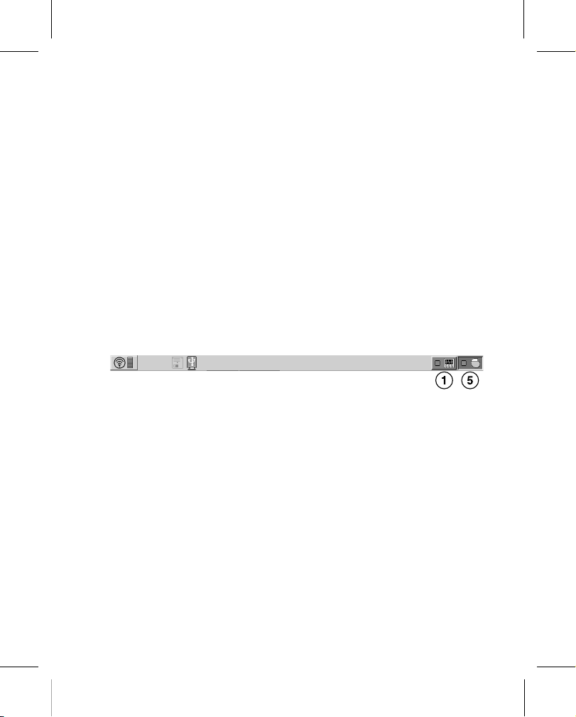
1. From the device session, launch a new analyzer session by tapping the analyzer icon on the task bar.
2. Measure the R Wave amplitude with the analyzer:
3. To confirm the measurement values, remeasure the R Wave amplitude if you choose.
4. Manually record the R Wave amplitude measurement to enter into the patient’s record.
5. Tap the device icon on the task bar.
6. Tap Patient > Patient Information > Implant… field to display the Implant pop-up window.
7. Manually enter the measurements you recorded in Step 4 in the Lead Data from Analyzer fields.
8. To save the measurement values into device memory, tap OK > Program.
3.4 Connecting the lead to the device
The following procedure describes how to connect the lead to the device, how to confirm that the lead connector
is fully inserted in the connector block, and how to verify that the lead connection is secure.
Warning: After connecting the lead, verify that the lead connection is secure by gently tugging on the lead. A loose
lead connection may result in inappropriate sensing, which can cause inappropriate arrhythmia therapy or a failure
to deliver arrhythmia therapy.
Caution: Use only the torque wrench supplied with the device. The torque wrench is designed to prevent damage
to the device from overtightening a setscrew.
See Figure 1 for information about the lead connector port on the device.
503196-012
21
M972448A001 A Medtronic Confidential Composed: 2018-12-21 13:48:44
XSL-Stylesheet B - Implant manual 27-AUG-2018
Page 22

1a 1b
Printing instructions: doc #163256
Category: Implant manual
Size: 4.625 x 6 in (117 x 152 mm)
Figure 1. Lead connector port
1 EV4-LLHH connector port
2 Device Active Can electrode
3.4.1 How to connect the lead to the device
1. Insert the torque wrench into the appropriate setscrew.
a. If the setscrew obstructs the port, retract the setscrew by turning it counterclockwise until the port is clear.
Take care not to disengage the setscrew from the connector block (see Figure 2).
b. To allow a pathway to vent trapped air when the lead connector is inserted into the connector port, leave
the torque wrench in the setscrew until the lead connection is secure (see Figure 2).
Figure 2. Inserting the torque wrench into the setscrew
503196-012
2. Insert the lead connector into the connector port, keeping twisting to a minimum. Insert the lead connector
until the lead connector pin is visible in the pin viewing area. No sealant is required.
3. Confirm that the lead is fully inserted into the connector pin cavity by viewing the device connector block from
the side. The tip of the lead connector pin is visible in the pin viewing area when the pin is fully inserted (see
Figure 3).
22
M972448A001 A Medtronic Confidential Composed: 2018-12-21 13:48:44
XSL-Stylesheet B - Implant manual 27-AUG-2018
Page 23

Printing instructions: doc #163256
Category: Implant manual
Size: 4.625 x 6 in (117 x 152 mm)
Figure 3. Confirming the EV4-LLHH lead connection
4. Tighten the setscrew by turning it clockwise until the torque wrench clicks. Remove the torque wrench.
5. Gently tug on the lead to confirm a secure fit. Do not pull on the lead until the setscrew has been tightened.
3.5 Positioning and securing the device
Caution: Program tachyarrhythmia detection to OFF to avoid inappropriate detection or therapy delivery while
closing the surgical pocket.
Note: Implant the device under the patient’s adipose tissue, against the muscle tissue. Face the side of the device
engraved with the Medtronic logo toward the skin so the patient can better hear any alert tones. This orientation is
also most compatible with the device PhysioCurve Design.
3.5.1 How to position and secure the device
1. Verify that the lead connector pin is fully inserted into the connector port and that the setscrew is tight.
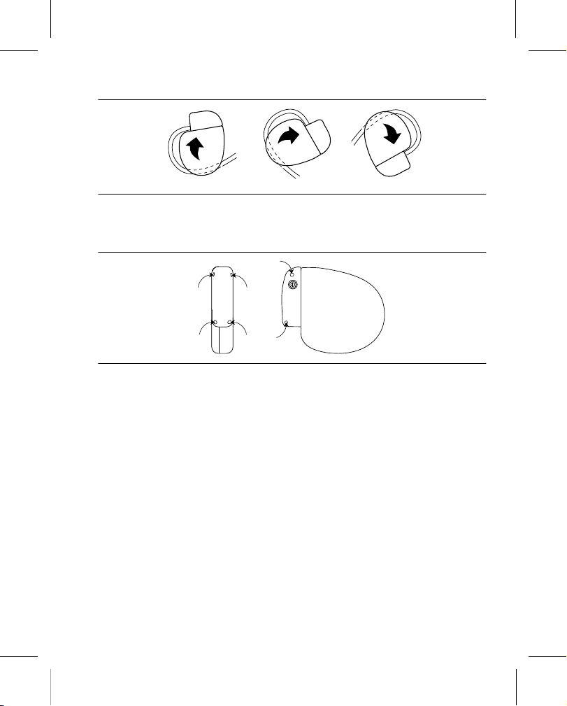
2. To prevent twisting of the lead body, rotate the device to loosely wrap the excess lead length (see Figure 4).
Do not kink the lead body.
503196-012
23
M972448A001 A Medtronic Confidential Composed: 2018-12-21 13:48:44
XSL-Stylesheet B - Implant manual 27-AUG-2018
Page 24
Printing instructions: doc #163256
Category: Implant manual
Size: 4.625 x 6 in (117 x 152 mm)
Figure 4. Rotating the device to wrap the lead
3. Place the device and the lead into the surgical pocket located in the left midaxillary region.
4. Use nonabsorbable sutures to secure the device within the pocket and minimize post-implant rotation and
migration. Use a surgical needle to penetrate the suture holes on the device (see Figure 5).
Figure 5. Locating the suture holes
5. Suture the pocket incision closed.
3.6 Performing a Sensing Test
The sensing test enables you to measure R-wave amplitude on any programmed Sense Polarity.
Considerations for performing a sensing test:
●
If no intrinsic events occur, the sensing test ends after a few seconds.
●
Tachyarrhythmia detection is suspended during the sensing test.
3.6.1 Selecting a sense polarity to test
Use the following steps to select a Sense Polarity that you wish to test:
1. Tap Params > Sensing… > Sense Polarity
2. In the Sense Polarity pop-up window, click on the electrodes shown, or select from the list at the bottom of
the window.
3. To program the selected polarity, tap Close > OK > PROGRAM
3.6.2 Performing a sensing test on the programmed polarity
Use the following steps to perform a sensing test on the programmed polarity:
1. Tap Tests > Sensing.
2. Tap START Measurement.
3. Observe the Live Rhythm Monitor for an intrinsic rhythm and amplitude measurements.
503196-012
24
M972448A001 A Medtronic Confidential Composed: 2018-12-21 13:48:44
XSL-Stylesheet B - Implant manual 27-AUG-2018
Page 25

Printing instructions: doc #163256
Category: Implant manual
Size: 4.625 x 6 in (117 x 152 mm)
Notes:
●
To abort the test, tap STOP and Restore.
●
The device measures amplitudes only on intrinsic events. The maximum amplitude value that the sensing
test can measure is 10 mV. If the amplitude is over 10 mV, the results are displayed as >10 mV.
The sensing test ends when it has measured 5 intrinsic events. When the test is complete, the R-Wave Amplitude
value is updated on the test screen. This value represents the median measured R-wave amplitude.
3.7 Performing a pacing threshold test
The pacing threshold test is used to determine the minimum pacing output that consistently captures the heart.
The results of this test also determine which S1 Pathway to use in the T-Shock defibrillation test in Section 3.8,
“Performing ventricular defibrillation threshold tests”, page 25.
3.7.1 How to measure pacing thresholds
1. Tap Tests > Pacing Threshold.
2. Select the Pace Polarity for the test, beginning with Ring 1 to Ring 2.
3. Select a Test Value for Lower Rate, Amplitude, and Pulse Width.
4. To change the value for V. Pace Blanking tap Additional Settings… to access the V. Pace Blanking | Test
Value field. Tap the field and select a Temp. V. Pace Blanking value, then tap OK.
5. Select the Enable check box.
Note: When you are testing the Coil 2 to Coil 1 polarity, the Energy Check - In Progress pop-up appears
briefly to determine the stored capacitor energy. If the energy on the capacitors is higher than the energy level
you selected for the test, the programmer displays a warning. To clear this warning, tap either DUMP to dump
the capacitors, or CANCEL.
6. Press and hold TEST Press and Hold.
7. Observe the Live Rhythm Monitor for capture or loss of capture.
8. If capture is lost, perform the following procedure. (If capture is not lost, go to Step 9.)
a. Release TEST Press and Hold. The device resumes OVO mode operation and displays the Test -
Pacing Threshold - Results window.
b. Tap Close to return to the Tests - Pacing Threshold screen.
c. Repeat Step 3 through Step 7 using incrementally higher values until capture is not lost. These values
comprise the pacing threshold for the Ring 1 to Ring 2 pace polarity.
9. If capture is not lost, perform the following procedure.
a. Release TEST Press and Hold. The device resumes OVO mode operation and displays the Test -
Pacing Threshold - Results window.
b. Tap Close to return to the Tests - Pacing Threshold screen.
c. Repeat Step 3 through Step 7 using incrementally lower values until capture is lost. The lowest tested
values at which capture is not lost comprise the pacing threshold for the Ring 1 to Ring 2 pace polarity.
10. To identify the pacing thresholds for the Ring 1 to Coil 2 and Coil 2 to Coil 1 pace polarities, repeat Step 3
through Step 9.
Note: The pacing amplitude range for the Ring 1 to Ring 2 and Ring 1 to Coil 2 pace polarities is 1.00 V to
8.00 V. If you are unable to capture the heart at a pacing amplitude of ≤8.00 V at any pulse width, you must
pace from the Coil 2 to Coil 1 pace polarity. The pacing amplitude range for the Coil 2 to Coil 1 pace polarity
is 10.00 V to 30.00 V for Post Shock pacing, 10.00 V to 30.00 V for ATP, and 10.00 V or 13.00 V for Pause
Prevention pacing.
11. To print a Pacing Threshold test report at any time, tap Print… from the Tests - Pacing Threshold - Results
window.
3.8 Performing ventricular defibrillation threshold tests
Test the operation and effectiveness of ventricular defibrillation by inducing VF with the T-Shock test or the Burst
Induction test, and then allow the device to detect and treat the VF with programmed therapies. Establish an
adequate sensing safety margin and an adequate defibrillation safety margin using your preferred method.
503196-012
25
M972448A001 A Medtronic Confidential Composed: 2018-12-21 13:48:44
XSL-Stylesheet B - Implant manual 27-AUG-2018
Page 26

Printing instructions: doc #163256
Category: Implant manual
Size: 4.625 x 6 in (117 x 152 mm)
Carefully consider for each patient the decision to induce VF for testing ventricular defibrillation operation and
effectiveness. Use discretion in your decision to test or how to test for an adequate safety margin.
3.8.1 High-voltage implant values
See Table 2 for information about the measured high-voltage therapy values that are recommended at implant.
Table 2. High-voltage (HV) therapy values recommended at implant
Measurement Values
HV delivery pathway impedance 30–250 Ω
Demonstrated defibrillation success 30 J
3.8.2 How to prepare for defibrillation threshold testing
Warning: Keep external defibrillation equipment nearby for immediate use. Potentially harmful spontaneous or
induced tachyarrhythmias may occur during device testing, implant procedures, and post-implant testing.
1. Establish telemetry between the device and programmer, and start a patient session. If you are using wireless
telemetry, verify that at least 3 of the green lights on the wireless telemetry icon are illuminated. Interrogate
the device if it has not been interrogated.
2. To verify that the device is sensing properly, observe the Marker Channel annotations. Tap Params >
Sensing… to adjust the sensing parameters, if necessary.
3. Perform a manual Lead Impedance Test to verify defibrillation lead connections. For information about
acceptable impedance values, refer to the Medtronic extravascular lead technical manual. Perform this test
with the device in the surgical pocket. Keep the surgical pocket moist. If the lead impedance is out of range,
perform one or more of the following tasks:
●
Recheck the lead connections and lead electrode placement.
●
Inspect the EGM for abnormalities.
●
Repeat the manual Lead Impedance Test.
4. If desired, enable post shock pacing before performing defibrillation threshold testing. To turn on post shock
pacing, perform the following steps:
●
Tap Params > Pacing… > Post Shock | Setting. The Post Shock Pacing Enable pop-up displays.
●
Tap Off. The field will toggle to On.
5. Change the Amplitude, Pulse Width and Pace Polarity values, as desired.
6. Tap OK > PROGRAM to program your parameter changes into device memory.
3.8.3 How to perform defibrillation threshold testing using T-Shock
Note: During a wireless telemetry session, you cannot deliver a T-Shock induction when there is a magnet or
programming head over the device.
1. Tap Tests > EP Study > T-Shock.
2. Tap Adjust Permanent… and make the following selections in the Adjust Permanent window:
a. Set the Energy parameter for Rx1 to 30 J (or 10 J less than your desired final programmed value).
b. Set the Energy parameter for Rx2, Rx3, Rx4, Rx5, and Rx6 to 40 J (or 10 J greater than the value you
selected in Step 2a).
c. Tap the Sensitivity parameter and select a value for a safety margin for detecting VF that is at least 2x the
final programmed sensitivity.
Note: For a final programmed sensitivity of 0.2 mV, an adequate safety margin typically is attained if you
set the value to 0.45 mV during testing.
d. Set VF Enable to On.
e. Tap PROGRAM.
f. Tap Close to close the Adjust Permanent window.
503196-012
26
M972448A001 A Medtronic Confidential Composed: 2018-12-21 13:48:44
XSL-Stylesheet B - Implant manual 27-AUG-2018
Page 27

Printing instructions: doc #163256
Category: Implant manual
Size: 4.625 x 6 in (117 x 152 mm)
3. Select the S1 Pathway based on the results of the pacing threshold test (see Section 3.7, “Performing a
pacing threshold test”, page 25) as follows:
●
If the pacing threshold is below 8 V, 8 ms, select Ring 1 to Coil 2.
●
If the pacing threshold is above 8 V, 8 ms, select Coil 2 to Coil 1.
4. Set the desired T-Shock parameters.
5. Check the Enable check box. (The Energy Check - In Progress pop-up appears briefly to determine the
stored capacitor energy.)
Note: If the energy on the capacitors is higher than the energy level you selected for the test, the programmer
displays a warning. To clear this warning, tap either DUMP to dump the capacitors, or CANCEL.
6. Tap DELIVER T-Shock. If necessary, tap ABORT to abort the induction.
7. Observe the Live Rhythm Monitor for proper detection, therapy, and post-shock sensing.
8. Tap Retrieve Data… to review the stored data for the induced episode. To view more details, tap Print… to
print an EP Study T-Shock Induction Report, or tap Data > Clinical Diagnostics > Arrhthmia Episodes to
view the induced episode data on the programmer.
9. Tap Adjust Permanent… to program new Therapy Energy levels or to change the Pathway, if desired.
Note: If sensing parameters other than Sensitivity need to be adjusted, tap Params > Sensing… to
reprogram those parameters. The Last Induction (mm:ss) timer will continue to count while you do this.
10. Wait until the Last Induction (mm:ss) timer reaches at least 05:00, then repeat Step 1 through Step 10, as
needed.
3.8.4 How to perform defibrillation threshold testing using Burst Induction
1. Tap Tests > EP Study > Burst Induction.
2. Tap Adjust Permanent… and make the following selections in the Adjust Permanent window:
a. Set the Energy parameter for Rx1 to 30 J (or 10 J less than your desired final programmed value).
b. Set the Energy parameter for Rx2, Rx3, Rx4, Rx5, and Rx6 to 40 J (or 10 J greater than the value you
selected for Rx1 in Step 2a).
c. Tap the Sensitivity parameter and select a value that results in an adequate safety margin for detecting
VF. For a final programmed sensitivity of 0.2 mV, an adequate safety margin typically is attained by setting
the value to 0.45 mV during testing.
d. Set VF Enable to On.
e. Tap PROGRAM.
f. Tap Close to close the Adjust Permanent window.
3. Select the Enable check box. (The Energy Check - In Progress window appears briefly to determine the
stored capacitor energy.)
Note: If the energy reserved on the capacitors is greater than the energy that is required to perform the Burst
Induction test, the programmer displays a warning. To clear this warning, tap either DUMP to dump the
capacitors, or CANCEL.
4. Press and hold the touch pen on the BURST Press and Hold button. The test aborts if you lift the touch pen.
If you do not lift the touch pen, the test times out after 10 s.
5. Observe the Live Rhythm Monitor for proper detection, therapy, and post-shock sensing.
6. Tap Retrieve Data… to review the stored data for the induced episode. To view more details, tap Print… to
print an EP Study Burst Induction Report.
7. Tap Adjust Permanent… to program a new Rx1 energy level or to change the Pathway, if desired.
Note: If sensing parameters other than Sensitivity need to be adjusted, tap Params > Sensing… to
reprogram those parameters. The Last Induction (mm:ss) timer will continue to count while you do this.
8. Wait until the Last Induction (mm:ss) timer reaches at least 05:00, then repeat Step 3 through Step 8, as
needed.
3.9 Completing the implant procedure
3.9.1 How to complete programming the device
1. Enable tachyarrhythmia detection and the desired tachyarrhythmia therapies.
2. Verify that the sensing, pacing, detection, and therapy parameters are programmed to values that are
appropriate for the patient.
503196-012
27
M972448A001 A Medtronic Confidential Composed: 2018-12-21 13:48:44
XSL-Stylesheet B - Implant manual 27-AUG-2018
Page 28

Printing instructions: doc #163256
Category: Implant manual
Size: 4.625 x 6 in (117 x 152 mm)
3. Perform a final VF induction, and allow the implanted system to detect and treat the tachyarrhythmia.
4. Enter the patient’s information.
Note: Enter complete information about the implanted lead in the Patient Information screen.
Note: Enter complete information about other hardware implanted in the patient in the MRI SureScan
System/Other Hardware screen. Include concomitant or abandoned devices or leads, and lead extenders
or adaptors. This information is used if the patient needs to be evaluated for an MRI scan. For more
information, see the reference manual.
5. Configure the Medtronic CareAlert feature.
6. Program the Data Collection Setup parameters.
3.9.2 How to assess the performance of the device and lead
After implanting the device, x-ray the patient as soon as possible to verify device and lead placement. Before the
patient is discharged from the hospital, assess the performance of the implanted device and lead.
1. Monitor the patient’s electrocardiogram until the patient is discharged. If the lead migrates or dislodges, it
usually occurs during the immediate postoperative period.
2. If any tachyarrhythmia therapies are enabled while the patient is in the hospital, interrogate the device after
any spontaneous episodes to evaluate the detection and therapy parameter settings.
3. If the patient has not experienced spontaneous episodes, you can induce tachyarrhythmias with one of the
EP Study tests to assess further the performance of the system.
4. Check the pacing and sensing values, and adjust the values if necessary. Verify the safety margin for the
pacing threshold, and verify the sensing safety margin for detecting VF.
5. Demonstrate the alert tones.
6. To document the postoperative programmed device status, interrogate the device and print a final report.
4 Replacement procedure
4.1 Replacing a device
To retain the ability to scan the SureScan system safely during future MRI scans, refer to the MRI
technical manual for additional information.
Warning: Keep external defibrillation and pacing equipment nearby for immediate use. The patient does not
receive defibrillation or pacing therapy from the device when the lead is disconnected.
Warning: A Medtronic Model EV2401 EV4-LLHH extravascular quadripolar lead must be used with the Medtronic
Model DVEX3E4 EV ICD device. If a lead other than a Medtronic Model EV2401 EV4-LLHH extravascular
quadripolar lead is used, the EV ICD system will present serious risks for adverse events to the patient.
Caution: Disable tachyarrhythmia detection to avoid inappropriate therapy delivery while explanting the device.
4.1.1 How to explant and replace a device
1. Disable tachyarrhythmia detection, Post Shock pacing and Pause Prevention detection to avoid potential
inappropriate shocks to the patient or clinician while explanting the device.
2. Dissect the lead and the device free from the surgical pocket. Do not nick or breach the lead insulation.
3. Use a torque wrench to loosen the setscrew in the connector block.
4. Gently pull the lead out of the connector port.
5. Evaluate the condition of the lead (see Section 3.8, “Performing ventricular defibrillation threshold tests”,
page 25). Replace the lead if the electrical integrity is not acceptable or if the lead connector pin is pitted or
corroded. If you explant the lead, return it to Medtronic for analysis and disposal.
6. Connect the lead to the replacement device (see Section 3.4, “Connecting the lead to the device”, page 21).
7. Perform a sensing test on the replacement device. See Section 3.6, “Performing a Sensing Test”, page 24.
8. Perform a pacing threshold test on the replacement device. See Section 3.7, “Performing a pacing threshold
test”, page 25.
503196-012
28
M972448A001 A Medtronic Confidential Composed: 2018-12-21 13:48:44
XSL-Stylesheet B - Implant manual 27-AUG-2018
Page 29

Printing instructions: doc #163256
Category: Implant manual
Size: 4.625 x 6 in (117 x 152 mm)
9. Perform ventricular defibrillation threshold tests to evaluate the defibrillation effectiveness of the replacement
device. See Section 3.8, “Performing ventricular defibrillation threshold tests”, page 25.
10. Position and secure the device in the surgical pocket, and suture the pocket incision closed (see Section 3.5,
“Positioning and securing the device”, page 23).
11. Contact Medtronic for return mailer kits to return explanted devices for analysis and disposal. See the back
cover for addresses.
Note: Observe all local laws and regulations regarding the disposal of explanted devices or leads.
5 Product specifications
5.1 Physical characteristics
Table 3. Physical characteristics
a
Volume
Mass 77 g
H x W x D 64 mm x 51 mm x 13 mm
Surface area of device can 57 cm
Connector
Type EV4-LLHH
Length 30 mm
Functional diameter 3.2 mm
Radiopaque ID
Materials in contact with human tissue
b
c
Battery chemistry Hybrid CFx lithium/silver vanadium oxide
Battery model M970710A
a
Volume with connector ports unplugged.
b
The radiopaque ID and Medtronic radiopaque identifier can be viewed in a fluoroscopic image of the device.
c
These materials have been successfully tested for the ability to avoid biological incompatibility. The device does
not produce an injurious temperature in the surrounding tissue during normal operation.
3
33 cm
2
REX
Titanium, polyurethane, silicone rubber
503196-012
29
M972448A001 A Medtronic Confidential Composed: 2018-12-21 13:48:44
XSL-Stylesheet B - Implant manual 27-AUG-2018
Page 30

Printing instructions: doc #163256
Category: Implant manual
Size: 4.625 x 6 in (117 x 152 mm)
Figure 6. Connector ports and suture holes
503196-012
1 EV4-LLHH connector port
2 Device Active Can electrode
The EV ICD model DVEX3E4 shield graphics are shown in Figure 7.
Figure 7. Shield graphics: EV ICD model DVEX3E4
1 EV4-LLHH marking
3 Suture holes
5.2 Electrical specifications
Table 4. Basic battery characteristics and battery and device specifications
Battery characteristics
Manufacturer Medtronic Energy and Component Center
Model M970710A
Chemistry Hybrid CFx lithium/silver vanadium oxide
Battery electrical specifications
Nominal voltage 3.2 V
Mean capacity to RRT 1.0 Ah
Minimum capacity after RRT 0.1 Ah
30
M972448A001 A Medtronic Confidential Composed: 2018-12-21 13:48:44
XSL-Stylesheet B - Implant manual 27-AUG-2018
Page 31

Printing instructions: doc #163256
Category: Implant manual
Size: 4.625 x 6 in (117 x 152 mm)
Table 4. Basic battery characteristics and battery and device specifications (continued)
Device electrical specifications
Input impedance 150 kΩ minimum
503196-012
Table 5. Peak ICD output voltage during high-voltage shock delivery
Minimum 0.4 J (±0.25 J) 71 V (±16%) 33 V (±30%)
Mean 20 J (±20%) 515 V (±10%) 255 V (±25%)
Maximum 40 J (±15%) 730 V (±10%) 360 V (±25%)
5.2.1 Output waveforms
Figure 8. Output waveform shapes
1 ≤8 V pace waveform (8 ms)
2 ≥10 V pace waveform (2 paces shown)
5.2.2 Measuring methods
Device parameters, such as pulse duration, pulse amplitude, and sensitivity, are measured at 37°C ±2°C and
500 Ω ±1% load according to standard ISO 14708-2:2012.
Pulse duration – Pulse duration is measured at 1/3 peak voltage levels according to standard ISO 14708-2:2012
(see Figure 9). When you apply this measurement method, the measured pulse width W depends on the load
Rload (in ohms) and programmed pulse width Wp (in seconds) with tolerance W ≤ Wp + 34 µs and W ≥ the smaller
of (Wp - 16 µs) or [124 µs + (4 µs x Rload)].
Amplitude – The pulse amplitude is calculated according to standard ISO 14708-2:2012 (see Figure 9). When
you apply this measurement method, the measured amplitude A depends on the programmed amplitude Ap and
programmed pulse width Wp: A = Ap x [0.9 – (Wp x 0.145 ms-1)]. The tolerance (+40%/-30% for voltages less than
2.0 V, and ±30% for voltages greater than or equal to 2.0 V) is applied not to the programmed setting, but to the
calculated amplitude A.
Programmed energy Peak voltage for first pulse
phase
3 Monophasic high-voltage waveform (T-Shock
inductions only)
4 Biphasic high-voltage waveform
Peak voltage for second
pulse phase
31
M972448A001 A Medtronic Confidential Composed: 2018-12-21 13:48:44
XSL-Stylesheet B - Implant manual 27-AUG-2018
Page 32

2 ms
15 ms
Printing instructions: doc #163256
Category: Implant manual
Size: 4.625 x 6 in (117 x 152 mm)
Figure 9. Measurement of pulse duration and amplitude
503196-012
1 Maximum amplitude
2 1/3 maximum amplitude
4 Time integral over voltage (F)
5 Pulse amplitude (A)
3 Pulse duration (D)
Sensitivity – Sensitivity is defined as the lowest voltage amplitude of a test signal that the device can sense. The
programmable values for sensitivity assume a 40 ms sine2 waveform. When using the test signal defined in ISO
14708-2:2012 (see Figure 10), the rated ventricular sensing threshold will be 1.5 times the programmed sensitivity
value.
Figure 10. Measurement of sensitivity
1 Amplitude
Notes:
●
If you measure pacing and sensitivity parameters with a pacing system analyzer, you may observe
considerable variance from the specifications presented in this manual. If so, it is because the pacing system
analyzers do not use the same measuring methods as defined in ISO 14708-2:2012.
●
Electrocardiogram monitoring equipment can distort lead impedance measurements.
Common mode rejection ratio – The common mode rejection ratio (CMRR) for frequencies 16.6 Hz, 50 Hz, and
60 Hz is at least 100 (40 dB). The calculation of the CMRR ratio was done based on measurements performed with
the sinusoidal waveform injected directly into the device. The device and lead system CMRR ratio depends on
several factors, such as the placement of the electrodes or electrode separation, and may be lower than the device
CMRR ratio.
32
M972448A001 A Medtronic Confidential Composed: 2018-12-21 13:48:44
XSL-Stylesheet B - Implant manual 27-AUG-2018
Page 33

Printing instructions: doc #163256
Category: Implant manual
Size: 4.625 x 6 in (117 x 152 mm)
5.2.3 Variation with temperature
Basic rate, test pulse rate, pulse duration, and pulse amplitude remain within expected tolerances when the device
temperature is between 22°C and 45°C (72°F to 113°F). Sensitivity at nominal conditions as measured at 37°C
(98.6°F) can vary as much as ±1% per °C from 22°C to 45°C (72°F to 113°F).
5.3 Replacement indicators
The Remaining Longevity estimate, replacement status, and battery voltage appear on the programmer display
and on printed reports. The Recommended Replacement Time (RRT) and the End of Service (EOS) conditions
are listed in Table 6.
Table 6. Replacement indicators
Recommended Replacement Time (RRT) <2.73 V on 3 consecutive daily automatic measure-
ments
End of Service (EOS) 3 months after RRT
Remaining Longevity – The Remaining Longevity estimate displays the estimated time remaining until device
RRT.
RRT (Recommended Replacement Time) – The programmer displays the RRT battery status to indicate that
replacement of the device is recommended.
RRT date – The programmer displays the date when the battery reached RRT on the Quick Look II and Battery and
Lead Measurements screens.
EOS (End of Service) – The programmer displays the EOS battery status to indicate that the device should be
replaced immediately and may not operate per specifications.
Replace at EOS – If the programmer indicates that the device is at EOS, replace the device immediately.
Prolonged Service Period – The Prolonged Service Period (PSP) is the time between the RRT and EOS. The
PSP is defined as 3 months assuming the following conditions: 0% pacing; 6 full-energy charges delivered, at the
connector block, into a 50 Ω load. The EOS may be indicated before the end of 3 months if the device exceeds
these conditions.
5.4 Projected service life
The service life projection for the device is 11.7 years, based on the following assumptions:
●
Pacing at 0%.
●
2 high-voltage therapies per year.
●
Pre-arrhythmia EGM storage programmed to On for 6-months, over life of device.
●
Wireless telemetry:
– 3 hours of telemetry enabled at implant.
– 30 min of telemetry enabled for quarterly scheduled CareLink Monitor remote sessions (if available).
– 1 hour of in-office wireless telemetry enabled annually.
●
Shelf storage life of 5 months, before implant.
5.4.1 Projected service life considerations
Additional full-energy charges – Each additional full-energy charge due to therapy shock or device testing
reduces projected service life by approximately 46 days.
Pre-arrhythmia EGM storage – Full-time use of Pre-arrhythmia EGM storage reduces projected service life by
approximately 3.7 additional months per year, or 31%.
503196-012
33
M972448A001 A Medtronic Confidential Composed: 2018-12-21 13:48:44
XSL-Stylesheet B - Implant manual 27-AUG-2018
Page 34

Printing instructions: doc #163256
Category: Implant manual
Size: 4.625 x 6 in (117 x 152 mm)
Medtronic patient monitor remote transmissions – Additional Medtronic patient monitor remote
transmissions reduce projected service life. Projected service life reductions for more frequent remote
transmission rates are as follows:
●
Monthly transmissions over the life of the device reduce projected service life by 99 days, or 2%.
●
Weekly transmissions over the life of the device reduce projected service life by 468 days, or 9%.
●
Daily transmissions over the life of the device reduce projected service life by 2031 days, or 41%
●
A single additional transmission reduces projected service life by approximately 0.8 days, or 0.02%.
Wireless telemetry – Each hour of wireless telemetry use (in-office or at implant) reduces the projected service
life by approximately 11.7 days, or 0.27%.
Shelf storage time – Maximum shelf storage time of 18 months reduces projected service life by approximately
4.6%.
5.5 Energy levels and typical charge times
Energy levels – Stored energy is always greater than the delivered energy. Stored energy is derived from the peak
capacitor charge.
Typical charge times – The most recent capacitor charge time appears on the programmer display and on
printed reports. You can evaluate charge time using the Charge/Dump Test.
Table 7. Maximum energy levels and typical full energy charge times
Maximum programmed energy 40 J
Maximum delivered energy
Typical charge time at Beginning of Service (BOS)
Typical charge time at Recommended Replacement Time (RRT)
a
Energy delivered at connector block into a 75 Ω load.
b
Tolerance for delivered energy delivered into a 75 Ω load is ±30%.
c
Charge time during a nonwireless telemetry session may be slightly higher.
a,b
c
48 J
9.4 s
c
14.8 s
5.6 Magnet application
When a magnet is placed near the device, tachyarrhythmia detection is suspended and no tachyarrhythmia
therapies are delivered. Alert tones sound if programmed. The device ignores the magnet in the programmer head
when telemetry communication is established through the programmer head. Before implant and for the first 6
hours after implant, the device does not sound audible tones when a magnet is placed over the device.
503196-012
6 Device parameters
6.1 Emergency settings
Table 8. Emergency settings
Parameter Selectable values
Defibrillation
Energy 0.4; 0.6 … 1.8; 2; 3 … 16; 18; 20; 22; 24; 25; 26; 28; 30;
Pathway STD
M972448A001 A Medtronic Confidential Composed: 2018-12-21 13:48:44
32; 35; 40 J
34
XSL-Stylesheet B - Implant manual 27-AUG-2018
Page 35

Printing instructions: doc #163256
Category: Implant manual
Size: 4.625 x 6 in (117 x 152 mm)
Table 8. Emergency settings (continued)
Parameter Selectable values
Cardioversion
Energy 0.4; 0.6 … 1.8; 2; 3 … 16; 18; 20; 22; 24; 25; 26; 28; 30;
32; 35; 40 J
Pathway STD
6.2 Tachyarrhythmia detection parameters
Table 9. Ventricular tachyarrhythmia detection parameters
Parameter Programmable values Shipped Reset
VF Detection
VF Initial Beats to Detect 12/16; 18/24; 24/32; 30/40 ; 45/60;
VF Beats to Redetect 6/8; 9/12; 12/16 ; 18/24; 21/28;
VF: Ventricular Interval
(Rate)
FVT Detection OFF ; via VF OFF OFF
FVT: Ventricular Interval
(Rate)
VT Detection On; OFF OFF OFF
VT Interval (Rate)
VT Initial Beats to Detect 12; 16 … 52; 76; 100 16 16
VT Beats to Redetect 8; 12 … 52 12 12
Monitor Monitor ; Off Off Off
Monitored VT Beats to
Detect
Monitor: Ventricular Interval
(Rate)
Wavelet …
Wavelet On ; Off; Monitor On Off
Template [date] None None
Match Threshold 40; 43; 46 …61 … 97% 61% 61%
Auto Collection On ; Off ON OFF
Rapid AF On ; Off ON OFF
Feature Match On ; Off ON OFF
SVT V. Limit
a
b
b
b
On ; OFF OFF On
60/80; 75/100; 90/120; 105/140;
120/160
24/32; 27/36; 30/40
30/40 30/40
12/16 12/16
240; 250 … 320 … 400 ms 320 ms 320 ms
200; 210 … 240 … 600 ms — —
280; 290 … 360 … 650 ms 360 ms 400 ms
16; 20; 24; 28; 32 … 56; 80; 110; 130 32 32
b
b
280; 290 … 450 … 650 ms 450 ms 450 ms
210; 220; … 260 … 650 ms 260 ms 260 ms
503196-012
35
M972448A001 A Medtronic Confidential Composed: 2018-12-21 13:48:44
XSL-Stylesheet B - Implant manual 27-AUG-2018
Page 36

Printing instructions: doc #163256
Category: Implant manual
Size: 4.625 x 6 in (117 x 152 mm)
Table 9. Ventricular tachyarrhythmia detection parameters (continued)
Parameter Programmable values Shipped Reset
Other Enhancements
b
Stability
Off ; 30; 40 …100 ms Off Off
Onset Off ; On; Monitor Off Off
Percent 72; 75; 78; 81 ; 84; 88; 91; 94; 97% 81% 81%
High Rate Timeout
VF Zone Only (min) Off; 0.25; 0.5; 0.75 ; 1; 1.25; 1.5; 1.75;
All Zones (min) Off ; 0.5; 1; 1.5 … 5; 6; 7 … 20; 22; 24;
2; 2.5; 3; 3.5; 4; 4.5; 5 min
26; 28; 30 min
0.75 min 0.75 min
— —
TWave On ; Off On Off
Noise
Sensed Noise On ; Off On Off
Morphology Noise On ; Off On Off
Sensed EMI On ; Off On Off
Shared Noise TimeoutcOff; 0.25; 0.50; 0.75; … 2.00;
a
Reset does not happen in the box. Table shows Reset value when implanted.
b
The measured intervals are truncated to a 10 ms multiple (for example, 457 ms becomes 450 ms). The device
uses this truncated interval value when applying the programmed criteria and calculating interval averages.
c
Therapy can be withheld by noise oversensing enhancements for up to the total timeout period.
2.503.0 … 4.00 min
3 min —
6.3 Ventricular tachyarrhythmia therapy parameters
Table 10. Ventricular tachyarrhythmia therapy parameters
Parameter Programmable values Shipped Reset
VF Therapies
VF Therapy Status On ; Off On On
Energy Rx1–Rx2: 0.4; 0.6 … 1.8; 2; 3 … 16; 18;
a
Pathway
20; 22; 24; 25; 26; 28; 30; 32; 35; 40 J
Rx3–Rx6: 10; 11 … 16; 18; 20; 22; 24;
25; 26; 28; 30; 32; 35; 40 J
Rx1–Rx4: STD ; REV
Rx5–Rx6: STD; REV
VT/FVT Therapies
VT/FVT Therapy Status Rx1–Rx6: On; Off Off Off
Therapy Type Rx1: CV; Burst ; Ramp
b
Energy
Rx2–Rx6: CV ; Burst; Ramp
Rx2–Rx6: 0.4; 0.6 … 1.8; 2; 3 … 16;
18; 20; 22; 24; 25; 26; 28; 30; 32; 35;
40 J
40 J 40 J
STD STD
— —
— —
503196-012
36
M972448A001 A Medtronic Confidential Composed: 2018-12-21 13:48:44
XSL-Stylesheet B - Implant manual 27-AUG-2018
Page 37

Printing instructions: doc #163256
Category: Implant manual
Size: 4.625 x 6 in (117 x 152 mm)
Table 10. Ventricular tachyarrhythmia therapy parameters (continued)
Parameter Programmable values Shipped Reset
a
Pathway
Rx2–Rx4: STD ; REV
Rx5–Rx6: STD; REV
— —
Burst therapy parameters
Initial # Pulses 1; 2 … 8 … 15 — —
R-S1 Interval=(%RR) 50; 53; 56; 59; 63; 66 … 84; 88 ; 91; 94;
97%
— —
Interval Dec 0; 10 … 40 ms — —
# Sequences 1; 2 … 10
Smart Mode
c
VT Therapies: 3
FVT Therapies: 1
On; Off — —
— —
Ramp therapy parameters
Initial # Pulses 1; 2 … 8 … 15 — —
R-S1 Interval=(%RR) 50; 53; 56; 59; 63; 66 … 84; 88; 91 ; 94;
97%
— —
Interval Dec 0; 10 … 40 ms — —
# Sequences 1; 2 … 10
Smart Mode
c
VT Therapies: 3
FVT Therapies: 1
On; Off — —
— —
Shared Settings…
Shared V. ATP
V-V Minimum ATP Interval 150; 160 … 200 … 400 ms (±12 msd /
±60 mse)
200 ms 200 ms
V. Amplitude 1; 2 … 8; 10; 13; 16; 20; 30 V 10 V 10 V
V. Pulse Width 1; 2; 3; 4; 6; 8 ms (±100 µs) 2 ms 2 ms
V. Pace Blanking 150; 160 … 250 … 450 ms (±5 ms) 250 ms 250 ms
ATP Polarity Ring 1 to Ring 2; Ring 1 to Coil 2; Coil 2 to
a
STD = Can to Coils; REV = Coils to Can.
b
This parameter is for CV (cardioversion).
c
Smart Mode is available only for Rx1– Rx4.
d
At ≤8 V amplitude.
e
At ≥10 V amplitude.
Coil 1
Coil 2 to Coil 1 Coil 2 to Coil 1
503196-012
37
M972448A001 A Medtronic Confidential Composed: 2018-12-21 13:48:44
XSL-Stylesheet B - Implant manual 27-AUG-2018
Page 38

Printing instructions: doc #163256
Category: Implant manual
Size: 4.625 x 6 in (117 x 152 mm)
6.3.1 Delivered energy conditions and tolerances
This table lists the conditions and tolerances for delivered energy levels for high voltage therapies.
Table 11. Delivered energy conditions and tolerances
30 Ω 50 Ω 75 Ω 200 Ω 250 Ω
22°C: 0.4 J -
a
35 J
-35% / +20% -30% / +20% -30% / +20% -30% / +20% -50% / +50%
22°C: 40 J -30% / +20% -30% / +20% -30% / +20% -30% / +20% -50% / +50%
37°C: 0.4 J - 4 Ja-30% / +20% -30% / +20% -30% / +20% -30% / +20% -50% / +50%
37°C: 5 J - 35 J -30% / +20% -20% / +20% -20% / +20% -30% / +20% -50% / +50%
37°C: 40 J -30% / +20% -15% / +15% -15% / +15% -30% / +20% -50% / +50%
45°C: 0.4 J -
a
40 J
a
Tolerance is ±0.25 J for energy levels for which ±0.25 J is greater than the listed tolerance range.
-30% / +20% -30% / +20% -30% / +20% -30% / +20% -50% / +50%
6.4 Post shock pacing parameters
Table 12. Post Shock pacing parameters
Parameter Programmable values Shipped Reset
Post Shock Pacing Enable On; Off Off Off
Amplitude 1 V (+0.18 V / -35%); 2; 3 … ; 7; 8 V
Pulse Width 2; 4 ms (±100 µs);
Pace Polarity Ring 1 to Ring 2; Ring 1 to Coil 2; Coil 2 to
e,f
Lower Rate
Therapy Duration
a
Ring 1 to Ring 2 or Ring 1 to Coil 2, nominal 500 Ω impedance.
b
Coil 2 to Coil 1, nominal 75 Ω impedance.
c
For ≤8 V amplitude, Ring 1 to Ring 2 or Ring 1 to Coil 2.
d
For ≥10 V amplitude, Coil 2 to Coil 1.
e
This parameter is nonprogrammable.
f
Escape interval at nominal pulse width of 8 ms is 992 ms.
e
(+15% / -35%)
10; 13; 16; 20; 30 V (+20% / -45%)
6; 8 ms (±10%)
1; 2 … 10 ms (±10%)
Coil 1
40 bpm (1500 ms) — —
30 s — —
a
c
c
d
10 V 10 V
b
— —
— —
503196-012
38
M972448A001 A Medtronic Confidential Composed: 2018-12-21 13:48:44
XSL-Stylesheet B - Implant manual 27-AUG-2018
Page 39

Printing instructions: doc #163256
Category: Implant manual
Size: 4.625 x 6 in (117 x 152 mm)
6.5 Pause Prevention Detection — detection and pacing parameters
Table 13. Pause Prevention Detection — detection and pacing parameters
Parameter Programmable values Shipped Reset
Setting
Pause Prevention Detection
Enable
Pause Prevention Detection
Interval
Amplitude 1 V (+0.18 V / -35%)
Pulse Width 2; 4 ms (±100 µs)
Pace Polarity Ring 1 to Ring 2; Ring 1 to Coil 2; Coil
e,f
Lower Rate
Therapy Duration
a
Ring 1 to Ring 2 or Ring 1 to Coil 2.
b
Coil 2 to Coil 1.
c
For ≤8 V amplitude, Ring 1 to Ring 2 or Ring 1 to Coil 2.
d
For ≥10 V amplitude, Coil 2 to Coil 1. Within ±10% for impedance ≥50 Ω and within ±20% for impedance <50 Ω.
e
This parameter is nonprogrammable.
f
Escape interval at nominal pulse width of 8 ms is 992 ms.
e
On; Off; Monitor Monitor Monitor
5; 6 … 15 s 5 s 10 s
a
2; 3 … 8 V (+15% / -35%)
10; 13 V (+20% / -45%)
c
6; 8 ms
1; 2 … 10 (±10% / ±20%) ms
a
b
c
2 to Coil 1
— —
— —
d
— —
40 bpm (1500 ms) — —
30 s — —
6.6 Sensing parameters
Table 14. Sensing parameters
Parameter Programmable values Shipped Reset
a,b,c
Sensitivity
Sense Polarity Ring 1 to Ring 2; Ring 1 to Can;
Blank after Sense 140; 150 … 200 ms 150 ms 150 ms
Sensing Threshold Decay Delay 210; 260 … 360 … 650 ms 360 ms 360 ms
Sensing Threshold Drop Time 500; 680; 1000; 1100 … 1500 ;
0.075; 0.100; 0.150 (±75%);
0.200; 0.300; 0.450; 0.600 (±50%);
0.900; 1.200 mV (±30%)
Ring 2 to Can
1600 … 2500 ms
0.300 mV 0.150 mV
Ring 1 to Ring2Ring 1 to Ring
1500 ms 1500 ms
503196-012
2
39
M972448A001 A Medtronic Confidential Composed: 2018-12-21 13:48:44
XSL-Stylesheet B - Implant manual 27-AUG-2018
Page 40

Printing instructions: doc #163256
Category: Implant manual
Size: 4.625 x 6 in (117 x 152 mm)
Table 14. Sensing parameters (continued)
Parameter Programmable values Shipped Reset
Blank after Pace 200; 210 … 250 … 450 ms 250 ms 250 ms
Oversensing Prevention Low - 1; 2; Medium - 3 ; 4; 5; High - 6;
a
Carefully evaluate the possibility of increased susceptibility to EMI and oversensing before changing the
sensitivity threshold to its minimum (most sensitive) setting of 0.075 mV. When susceptibility to modulated
interference is tested under the conditions specified in standard ISO 14708-2:2012, the device may sense the
interference if the sensitivity threshold is programmed to the minimum value of 0.075 mV. The device complies
with the standard requirements when the sensitivity threshold is programmed 0.3 mV or higher.
b
There is no nominal value for this parameter.
c
Programming Sense Polarity to a unipolar setting (Ring 1 to Can or Ring 2 to Can) will result in increased
susceptibility to EMI. Consider programming Sense Polarity to a bipolar setting whenever possible.
7 … 11; Max - 12
Medium - 3 Medium - 3
6.7 MRI SureScan parameters
Table 15. MRI SureScan parameters
Parameter Programmable values Shipped Reset
MRI SureScan On; Off Off Off
a
Timeout
a
Mode
Detection/Therapies
a
This parameter is nonprogrammable when the MRI SureScan feature is programmed to On.
6 hr — —
OVO — —
a
Off — —
6.8 Medtronic CareAlert parameters
Table 16. Clinical Management Alerts
Parameter Programmable values Shipped Reset
Number of Shocks Delivered in an Episode…
Device Tone
Alert Enable - Urgency Off ; On-Low; On-High Off Off
Number of Shocks Thresholdb1 ; 2; 3; 4; 5; 6 — —
Patient Home Monitor
c
Alert Enable Off ; On Off Off
Number of Shocks Thresholdb1 ; 2; 3; 4; 5; 6 — —
All Therapies in a Zone Exhausted for an Episode.
Device Tone
Alert Enable - Urgency Off ; On-Low; On-High Off Off
Patient Home Monitor
Alert Enable Off ; On Off Off
Number of Pause Prevention Episodes…
a
503196-012
40
M972448A001 A Medtronic Confidential Composed: 2018-12-21 13:48:44
XSL-Stylesheet B - Implant manual 27-AUG-2018
Page 41

Printing instructions: doc #163256
Category: Implant manual
Size: 4.625 x 6 in (117 x 152 mm)
Table 16. Clinical Management Alerts (continued)
Parameter Programmable values Shipped Reset
Device Tone
Alert Enable - Urgency Off ; On-Low; On-High Off Off
Number of Pause Prevention Episodes Threshold
b
1; 2; 3; 4; 5 — —
Patient Home Monitor
Alert Enable Off; On Off Off
Number of Pause Prevention Episodes Threshold
b
Alert Time (all others)… 00:00; 00:10 … 08:00 …
a
Note that VF, VT, and FVT therapies could be delivered during a single episode (from initial detection until
episode termination).
b
This parameter is displayed only when its related alert is enabled; a single parameter is shared between the
Device Tone and Patient Home Monitor alerts.
c
Alerts are programmable and transmittable to a monitor only when Patient Home Monitor is programmed to Yes.
1; 2; 3; 4; 5 — —
23:50
08:00 08:00
Table 17. Lead/Device Integrity Alerts
Parameter Programmable values Shipped Reset
Lead Impedance Out of Range…
Device Tone
Alert Urgency
a
Low; High High Off
Lead Impedance Enable
Ring 1 to Ring 2 On; Off (Observation only) On Off (Observation
Ring 1 to Coil 2 On; Off (Observation only) On Off (Observation
High Voltage On; Off (Observation only) On Off (Observation
only)
only)
only)
Patient Home Monitor
Lead Impedance Enable
b
Ring 1 to Ring 2 On; Off Off Off
Ring 1 to Coil 2 On; Off Off Off
High Voltage On; Off Off Off
Low Battery Voltage RRT…
Device Tone
Alert Enable - Urgency Off; On-Low; On-High On-High Off
Patient Home Monitor
Alert Enable
b
Off; On On Off
503196-012
41
M972448A001 A Medtronic Confidential Composed: 2018-12-21 13:48:44
XSL-Stylesheet B - Implant manual 27-AUG-2018
Page 42

Printing instructions: doc #163256
Category: Implant manual
Size: 4.625 x 6 in (117 x 152 mm)
Table 17. Lead/Device Integrity Alerts (continued)
Parameter Programmable values Shipped Reset
Excessive Charge Time EOS…
Device Tone
Alert Enable - Urgency Off; On-Low; On-High On-High Off
Patient Home Monitor
Alert Enable
b
Off; On On Off
VF Detection Off, 3+ VF or 3+ FVT Rx Off.
Device Tone
Alert Enable Off; On-High On-High On-High
Patient Home Monitor
Alert Enable
a
This parameter is displayed only if an associated alert has been enabled.
b
Alerts are programmable and transmittable to a monitor only when Patient Home Monitor is programmed to Yes.
b
Off; On On Off
Table 18. Shared parameters
Parameter Programmable values Shipped Reset
Patient Home Monitor Yes; No No No
Alert Time…
a
This parameter is displayed only if an associated alert has been enabled.
a
00:00; 00:10 … 08:00 … 23:50 08:00 08:00
6.9 Data collection parameters
Table 19. Data Collection Setup parameters
Parameter Programmable values Shipped Reset
LECG Source
LECG Range ±1; ±2; ±4; ±8 ; ±12; ±16; ±32 mV ±8 mV ±8 mV
EGM 1 Source Ring 1 to Ring 2 ; Ring 1 to Can; Ring
EGM 1 Range ±2; ±4; ±8 ; ±12; ±16; ±32 mV ±8 mV ±8 mV
EGM 2 (Wavelet) Source Ring 1 to Ring 2; Ring 1 to Coil 1; Ring
EGM 2 (Wavelet) Range ±1; ±2; ±4; ±8 ; ±12; ±16; ±32 mV ±8 mV ±8 mV
EGM 3 Source Coil 2 to Coil 1 ; Ring 1 to Ring 2; Coil
EGM 3 Range ±1; ±2; ±4; ±8 ; ±12; ±16; ±32 mV ±8 mV ±8 mV
a
Ring 1 to Ring 2; Ring 2 to Can ; Coil
2 to Ring 2
2 to Can; Coil 2 to Coil 1
1 to Coil 2; Coil 2 to Can ; Coil 1 to
Can; Ring 1 to Can; Ring 2 to Can;
Coil 2 to Coil 1
2 to Ring 2
Ring 2 to Can Ring 2 to Can
Ring 1 to Ring 2 Ring 1 to Ring 2
Coil 2 to Can Coil 2 to Can
Coil 2 to Coil 1 Coil 2 to Coil 1
503196-012
42
M972448A001 A Medtronic Confidential Composed: 2018-12-21 13:48:44
XSL-Stylesheet B - Implant manual 27-AUG-2018
Page 43

Printing instructions: doc #163256
Category: Implant manual
Size: 4.625 x 6 in (117 x 152 mm)
Table 19. Data Collection Setup parameters (continued)
Parameter Programmable values Shipped Reset
Stored (Ventricular) EGM1 and EGM2 ; EGM1 and
Pre-arrhythmia EGM Off ; On - 1 month; On - 3 months; On
Device Date/Time…
EGM3; EGM1 and LECG; EGM2 and
EGM3; EGM2 and LECG; EGM3 and
LECG
Continuous
b
(Enter time and date) On On
EGM1 and
EGM2
Off Off
Holter Telemetry Off ; 0.5; 1; 2; 4; 8; 16; 24; 36; 46 hr Off Off
a
LECG: this EGM channel displays morphology channel signals.
b
The times and dates stored in episode records and other data are determined by the Device Date/Time clock.
6.10 System test parameters
Table 20. System Test parameters
Parameter Selectable values
Tests – Sensing
Mode
Test Value OVO
Permanent OVO
Tests – Pacing Threshold
Pace Polarity Ring 1 to Ring 2; Ring 1 to Coil 2; Coil 2 to Coil 1
Mode
Test Value VVI
Permanent OVO
Lower Rate 30; 35 … 60; 70; 75 … 150 bpm
Amplitude 1.00; 1.50; … 8.00 V
Pulse Width 2.00; 4.00; 6.00; 8.00 ms
Additional Settings…
V. Pace Blanking 150; 160 … 450 ms
Tests – Wavelet
Wavelet enable Off; On ; Monitor
Match Threshold 40; 43 … 61 … 97
Auto Collection On ; Off
Mode OVO
EGM1 and
EGM2
503196-012
43
M972448A001 A Medtronic Confidential Composed: 2018-12-21 13:48:44
XSL-Stylesheet B - Implant manual 27-AUG-2018
Page 44

Printing instructions: doc #163256
Category: Implant manual
Size: 4.625 x 6 in (117 x 152 mm)
6.11 EP Study parameters
Table 21. T-Shock parameters
Parameter Selectable values
Enable (checked); (unchecked)
#S1 2; 3; 4; 5 ; 6 … 15
S1S1 300; 310 … 400 … 2000 ms
S1 Pathway Ring 1 to Coil 2 ; Coil 2 to Coil 1
Delay 120; 130 … 300 … 600 ms
T Energy 1 ; 1.2; 1.4 … 2; 3 … 16; 18; 20 J
a
Waveform
a
This parameter is nonprogrammable.
Table 22. Burst Induction parameters
Parameter Selectable values
Enable (checked); (unchecked)
Table 23. PES parameters
Parameter Selectable values
Enable (checked); (unchecked)
#S1 1; 2 … 8 ; 9 … 15
S1S1 150; 160 … 600 ; 610 … 2000 ms
S1S2 150; 160 … 400 ; 410 … 600 ms
S2S3 150; 160 … 400 ; 410 … 600 ms
S3S4 150; 160 … 400 ; 410 … 600 ms
Pace Polarity Ring 1 to Ring 2; Ring 1 to Coil 2; Coil 2 to Coil 1
Amplitude Ring 1 to Coil 1, Ring 1 to Coil 2: 8 V
Pulse Width Ring 1 to Coil 1, Ring 2 to Coil 2: 2; 4; 6; 8 ms
a
Default value when parameter is On is 400 ms.
Table 24. Defibrillation parameters
Parameter Selectable values
Enable (checked); (unchecked)
Energy 0.4; 0.6 … 1.8; 2; 3 … 16; 18; 20; 22; 24; 25; 26; 28; 30; 32;
Monophasic
a
a
Coil 2 to Coil 1: 10; 13; 16; 20; 30 V
Coil 2 to Coil 1: 1; 2; 3; 4 ms
35; 40 J
503196-012
44
M972448A001 A Medtronic Confidential Composed: 2018-12-21 13:48:44
XSL-Stylesheet B - Implant manual 27-AUG-2018
Page 45

Printing instructions: doc #163256
Category: Implant manual
Size: 4.625 x 6 in (117 x 152 mm)
Table 24. Defibrillation parameters (continued)
Parameter Selectable values
a
Waveform
Biphasic
Pathway STD ; REV
a
This parameters is nonprogrammable.
Table 25. Cardioversion parameters
Parameter Selectable values
Enable (checked); (unchecked)
Energy 0.4; 0.6 … 1.8; 2; 3 … 16; 18; 20; 22; 24; 25; 26; 28; 30;
32; 35; 40 J
Pathway STD ; REV
Table 26. Burst ATP parameters
Parameter Selectable values
Enable (checked); (unchecked)
# Pulses 1; 2 … 8 … 15
%RR Interval 50; 53; 56; 59; 63; 66 … 84; 88 ; 91; 94; 97%
Minimum Interval 150; 160 … 400 ms
Pace Polarity Ring 1 to Ring 2; Ring 1 to Coil 2; Coil 2 to Coil 1
a
Amplitude
Pulse Width Ring 1 to Coil 1, Ring 2 to Coil 2: 2; 4; 6; 8 ms
a
This parameter is nonprogrammable.
Ring 1 to Coil 1, Ring 1 to Coil 2: 8 V
Coil 2 to Coil 1: 10; 13; 16; 20; 30 V
Coil 2 to Coil 1: 1; 2; 3; 4 ms
503196-012
7 Explanation of symbols
The following symbols and abbreviations are printed on the Medtronic EV ICD Model DVEX3E4 package label.
Table 27. Explanation of symbols on package labeling
Symbol Explanation
SureScan symbol
MR Conditional. The Medtronic SureScan pacing system is safe for use in the MRI
environment when used according to the instructions in the SureScan technical
manual.
45
M972448A001 A Medtronic Confidential Composed: 2018-12-21 13:48:44
XSL-Stylesheet B - Implant manual 27-AUG-2018
Page 46

Printing instructions: doc #163256
Category: Implant manual
Size: 4.625 x 6 in (117 x 152 mm)
Table 27. Explanation of symbols on package labeling (continued)
Symbol Explanation
Open here
Open here
Do not use if package is damaged
Do not reuse
Sterilized using ethylene oxide
Consult instructions for use
Date of manufacture
Use by
503196-012
Reorder number
Serial number
Temperature limitation
Package contents
Implantable device
46
M972448A001 A Medtronic Confidential Composed: 2018-12-21 13:48:44
XSL-Stylesheet B - Implant manual 27-AUG-2018
Page 47

Printing instructions: doc #163256
Category: Implant manual
Size: 4.625 x 6 in (117 x 152 mm)
Table 27. Explanation of symbols on package labeling (continued)
Symbol Explanation
Implantable device, MR
ICD (single chamber, RV)
Non-standard connector cavity
Product documentation
Torque wrench
Sensitivity, RV
Therapies (delivered and stored), VF
Therapies (RV), VT, FVT
503196-012
Detection, VT, FVT, VF
Burst: RV
Ramp: RV
Defibrillation
V cardioversion
47
M972448A001 A Medtronic Confidential Composed: 2018-12-21 13:48:44
XSL-Stylesheet B - Implant manual 27-AUG-2018
Page 48

Printing instructions: doc #163256
Category: Implant manual
Size: 4.625 x 6 in (117 x 152 mm)
Table 27. Explanation of symbols on package labeling (continued)
Symbol Explanation
Active Can
Diameter
Use with
Extra-vascular lead
503196-012
48
M972448A001 A Medtronic Confidential Composed: 2018-12-21 13:48:44
XSL-Stylesheet B - Implant manual 27-AUG-2018
Page 49

Printing instructions: doc #163256
Category: Implant manual
Size: 4.625 x 6 in (117 x 152 mm)
503196-012
M972448A001 A Medtronic Confidential Composed: 2018-12-21 13:48:44
XSL-Stylesheet B - Implant manual 27-AUG-2018
Page 50

*M972448A001*
Printing instructions: doc #163256
Category: Implant manual
Size: 4.625 x 6 in (117 x 152 mm)
503196-012
Medtronic, Inc.
710 Medtronic Parkway
Minneapolis, MN 55432
USA
www.medtronic.com
+1 763 514 4000
© 2018 Medtronic
M972448A001 A
2018-12-21
Medtronic USA, Inc.
Toll-free in the USA (24-hour technical
consultation for physicians and medical
professionals)
Bradycardia: +1 800 505 4636
Tachycardia: +1 800 723 4636
Technical manuals
www.medtronic.com/manuals
M972448A001 A Medtronic Confidential Composed: 2018-12-21 13:48:44
XSL-Stylesheet B - Implant manual 27-AUG-2018
 Loading...