

Page 1
®
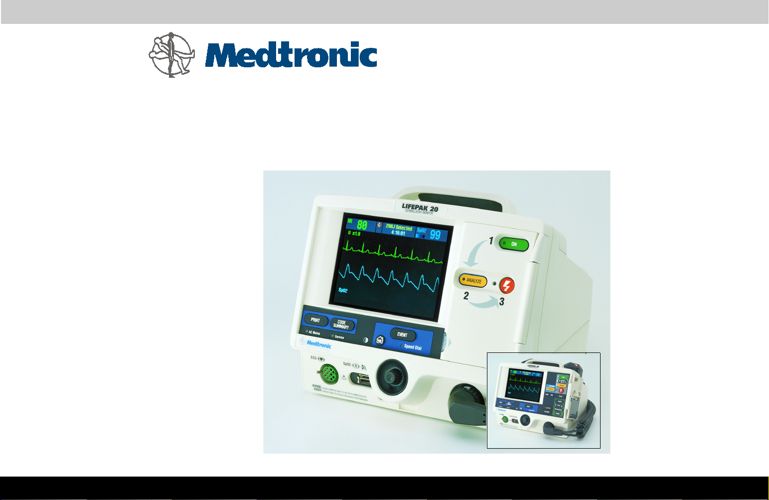
LIFEPAK
1
ADAPTIV
20
Defibrillator/Monitor with
Biphasic Technology
Service Manual
Click Here for Table of Contents Click Here for Navigation Help
Page 2

LIFEPAK 20 Defibrillator/Monitor Table of Contents
Click a Topic
Preface
Modes of
Operation
Preventive
Maintenance
Safety
Performance
Inspection
Battery
Maintenance
Device
Description
Instrument
Calibration
Replacement
Procedures
Operating
Instructions
Troubleshooting
Index
Title Page
Back
Index Next Page
Page 3

LIFEPAK 20 Defibrillator/Monitor Section Contents
Preface
This service manual describes how to maintain, test, troubleshoot, and repair the
LIFEPAK 20 defibrillator/monitor. A separate publication, the LIFEPAK 20
Defibrillator/Monitor Operating Instructions, is for use by physicians,
clinicians, and emergency care providers. The operating instructions provide
step-by-step instructions as well as operator-level testing and maintenance.
Note: Hyperlinks appear in blue text. Text that indicates a control, buttons,
message, or screen overlay appears as small caps. For example,
ADVISORY
This section covers the following topics:
control and
EVENT
button.
Trademarks
Using Bookmarks
Using Thumbnails
Navigating Through the Manual
Topic Navigation
Accessing Acrobat Help
Viewing Other Medtronic Documents
Service Personnel Qualifications
Previous Page Table of Contents
Back
Index Next Page
Page 4

LIFEPAK 20 Defibrillator/Monitor Preface
Preface
(Continued)
Contacting Medtronic
Responsibility for Information
Device Tracking
Service Information
Warranty Information
Configuration Information
Glossary
Acronyms
Previous Page Table of Contents Section Contents
Back
Index Next Page
Page 5

LIFEPAK 20 Defibrillator/Monitor Preface
Preface
Trademarks
1-5
PHYSIO-CONTROL, LIFEPAK, and FAST-PATCH are registered trademarks of
Medtronic Physio-Contol Corp.
QUIK-COMBO, CODE SUMMARY, REDI-PAK, PARTSLINE, Shock Advisory
System, and ADAPTIV are trademarks of Medtronic Physio-Control Corp.
Medtronic is a registered trademark of Medtronic, Inc.
MICROSOFT and WINDOWS are registered trademarks of Microsoft
Corporation in the US and/or other countries.
Pentium is a registered trademark of Intel Corporation.
Adobe and Acrobat are registered trademarks of Adobe Systems Incorporated.
Tektronix is a registered trademark of Tektronix Incorporated.
BIO-TEK is a registered trademark of Bio-Tek Instruments, Inc.
QED is a trademark of Bio-Tek Instruments, Inc.
ACCUSPLIT is a registered trademark of Accusplit Corporation.
Masimo is a registered trademark of Masimo Corporation.
©September 2002 Medtronic Physio-Control Corp. All rights reserved.
PN 3202007-000
Previous Page Table of Contents Section Contents
Back
Index Next Page
Page 6

LIFEPAK 20 Defibrillator/Monitor Preface
(C
)
Preface
Using Bookmarks
1-6
Bookmarks appear in a column on the left side of the screen. They enable you to
easily navigate to main sections of the manual, similar to a table of contents.
To view the bookmarks column:
■
Select the
■
Click the
BOOKMARKS
SHOW/HIDE NAVIGATION PANE
tab located to the far left of the screen.
button on the tool bar.
To close the bookmarks column:
■
Click the
SHOW/HIDE NAVIGATION PANE
button on the tool bar..
Previous Page Table of Contents Section Contents
Back
ontinued on next page
Index Next Page
Page 7

LIFEPAK 20 Defibrillator/Monitor Preface
Preface
Using Bookmarks
(Continued)
1-7
To move to a topic using bookmarks:
1. Display the bookmarks column.
2. Click the desired bookmark caption.
Note: A plus sign to the left of the bookmark caption indicates subordinate
bookmarks are available under that caption. Click the plus sign to reveal the
subordinate bookmarks. Click the plus sign a second time to hide the
subordinate bookmarks.
3. Click the bookmark text or double-click the page icon to the left of the
bookmark name to jump to the desired topic.
Previous Page Table of Contents Section Contents
Back
Index Next Page
Page 8

LIFEPAK 20 Defibrillator/Monitor Preface
Preface
Using Thumbnails
A thumbnail is a miniature view of each page in the document. You can use
thumbnails to jump quickly to a page.
To jump to a page by using its thumbnail:
1. Click the
Thumbnail images appear in the overview area of a window.
2. Click a thumbnail to move to the page it represents.
SHOW/HIDE NAVIGATION PANE
button to display thumbnail images.
1-8
Previous Page Table of Contents Section Contents
Back
Index Next Page
Page 9
LIFEPAK 20 Defibrillator/Monitor Preface
(C
)
Preface
Navigating Through the
Manual
To jump from topic to topic:
■
Click on any highlighted text or link to jump to that topic. The pointer
changes to a pointing finger when positioned over a link.
To jump from page to page:
■
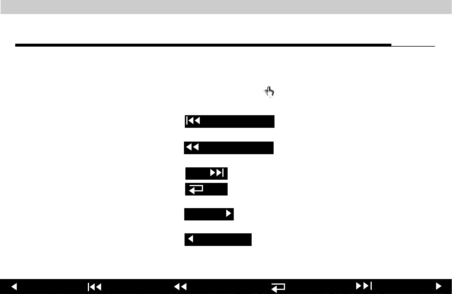
Click located in the page footer to jump to the
Table of Contents
table of contents.
■
Click located in the page footer to jump to the
Section Contents
section contents for the section you are currently viewing.
■
Click located in the page footer to jump to the index.
■
Click located in the page footer to retrace your steps in a
Index
Back
document, returning to each screen in the reverse order visited.
1-9
■
Click located in the page footer or press the
Next Page
your keyboard to jump to the next page of the manual.
■
Click located in the page footer or press the
Previous Page
on your keyboard to jump to the previous page of the manual.
Previous Page Table of Contents Section Contents
Back
RIGHT ARROW
LEFT ARROW
ontinued on next page
on
Index Next Page
Page 10

LIFEPAK 20 Defibrillator/Monitor Preface
Preface
Topic Navigation
Accessing Acrobat Help
1-10
On many pages in the manual, a second line of navigation options appears
directly above the page footer. This second line provides jumps between pages
with multiple topics that are closely related.
For additional assistance using the Acrobat Reader program that came with this
package, access
READER HELP
in the Help menu.
Previous Page Table of Contents Section Contents
Back
Index Next Page
Page 11

LIFEPAK 20 Defibrillator/Monitor Preface
Preface
Viewing Other
Medtronic Documents
1-11
The following additional online documents are included on this CD-ROM:
■
LIFEPAK 20 Defibrillator/Monitor Operating Instructions
■
LIFEPAK 20 Defibrillator/Monitor Performance Inspection Procedure
Checklist
You may view these documents by opening the file in Acrobat Reader or by
clicking a link to the appropriate document. Click on a document’s table of
contents, section contents, index, or bookmarks to jump to a specific area within
each document.
Previous Page Table of Contents Section Contents
Back
Index Next Page
Page 12

LIFEPAK 20 Defibrillator/Monitor Preface
Preface
Service Personnel
Qualifications
1-12
Service personnel must be properly qualified and thoroughly familiar with the
operation of the LIFEPAK 20 defibrillator/monitor. They must meet at least one of
the following requirements (or the equivalent):
■
Associate of Applied Science, with an emphasis in biomedical electronics
■
Certificate of Technical Training, with an emphasis in biomedical electronics
■
Equivalent biomedical electronics experience
Previous Page Table of Contents Section Contents
Back
Index Next Page
Page 13

LIFEPAK 20 Defibrillator/Monitor Preface
Preface
Contacting Medtronic
1-13
Medtronic Physio-Control
11811 Willows Road Northeast
Post Office Box 97006
Redmond, WA 98073-9706 USA
Telephone: 1.425.867.4000
Toll Free (USA only): 1.800.442.1142
Fax: 1.425.867.4121
Internet: www.physiocontrol.com
www.medtronic.com
Medtronic Europe S.A.
Medtronic Physio-Control
Rte. du Molliau 31
Case postale 84
1131 Tolochenaz
Switzerland
Telephone: 41.21.802.7000
Fax: 41.21.802.7900
Previous Page Table of Contents Section Contents
Back
Index Next Page
Page 14

LIFEPAK 20 Defibrillator/Monitor Preface
Preface
Responsibility for
Information
1-14
This service manual describes the methods required to maintain, test, and repair
the LIFEPAK 20 defibrillator/monitor. This manual does not cover operation of
the LIFEPAK 20 defibrillator/monitor. Qualified service personnel must consult
both the LIFEPAK 20 Defibrillator/Monitor Operating Instructions and the
LIFEPAK 20 Defibrillator/Monitor Service Manual to obtain a complete
understanding of the use and maintenance of the device.
It is the responsibility of our customers to ensure that the appropriate person(s)
within their organization have access to the information in this manual, including
any warnings and cautions used throughout the LIFEPAK 20 Defibrillator/Monitor
Service Manual.
Previous Page Table of Contents Section Contents
Back
Index Next Page
Page 15

LIFEPAK 20 Defibrillator/Monitor Preface
Preface
!USA
Device Tracking
1-15
The U.S. Food and Drug Administration requires defibrillator manufacturers and
distributors to track the location of their defibrillators. The address to which this
particular device was shipped is now listed as the current tracking location. If the
device is located somewhere other than the shipping address or the device has
been sold, donated, lost, stolen, exported, or destroyed, or if the device was not
obtained directly from Medtronic, please call the device tracking coordinator at
1.800.426.4448 to update this vital tracking information.
General information related to device tracking:
It is important to maintain accurate records of defibrillator location within your
facility or system. Maintenance of such records eases the process of locating
defibrillators should it be necessary to modify them. Defibrillators should be
tracked by both the manufacturer’s part number and serial number. Internal
asset or tracking numbers may also be useful in maintaining adequate control of
defibrillators.
Previous Page Table of Contents Section Contents
Back
Index Next Page
Page 16

LIFEPAK 20 Defibrillator/Monitor Preface
Preface
Service Information
1-16
Before attempting to clean or repair any assembly in this device, service
personnel should be familiar with the information provided in the Preventive
Maintenance section of this manual.
Service personnel should inspect any defibrillator that has been dropped,
damaged, or abused to verify that the device is operating within the performance
standards listed in the Performance Inspection Procedure (PIP), and that the
leakage current values are acceptable.
Replacement procedures for the LIFEPAK 20 defibrillator/monitor are limited to
those items accessible at the subassembly level. Replacements and
adjustments must be made by service personnel qualified by appropriate
training and experience. Replacements at the subassembly level simplify repair
and servicing procedures, and help ensure correct device operation and
calibration.
To obtain Medtronic service and maintenance for your LIFEPAK 20 defibrillator/
monitor, contact your local service or sales representative. In the USA, call
Medtronic Technical Services at 1.800.442.1142. Outside the USA, contact your
local Medtronic representative.
Previous Page Table of Contents Section Contents
Back
Index Next Page
Page 17

LIFEPAK 20 Defibrillator/Monitor Preface
Preface
Warranty Information
Masimo Use
Agreement
1-17
Refer to the warranty statement included in the LIFEPAK 20 Defibrillator/
Monitor Operating Instructions – Maintaining the Equipment.
No Implied License — Possession or purchase of this device does not convey
any express or implied license to use the device with replacement parts that
would, alone, or in combination with this device, fall within the scope of one or
more of the patents relating to this device.
Previous Page Table of Contents Section Contents
Back
Index Next Page
Page 18

LIFEPAK 20 Defibrillator/Monitor Preface
Preface
Configuration
Information
1-18
This service manual covers existing LIFEPAK 20 defibrillator/monitor devices
and options through the following revisions:
■
LIFEPAK 20 defibrillator/monitor basic device with ECG
■
Pacing Option
■
SpO2 Option
Previous Page Table of Contents Section Contents
Back
Index Next Page
Page 19

LIFEPAK 20 Defibrillator/Monitor Preface
(C
)
Preface
Glossary
The following are definitions of terms used throughout this service manual.
■
Automated External Defibrillator (AED) — The LIFEPAK 20
defibrillator/monitor uses an ECG analysis Shock Advisory System (SAS) to
advise the device operator if it detects a shockable or nonshockable rhythm.
For more information about CPSS and SAS, see the operating instructions
– Shock Advisory System.
■
Biphasic — Property of the shock waveform generated by the LIFEPAK 20
defibrillator/monitor. The biphasic waveform is characterized by a positive
current phase followed by a reverse current phase of shorter duration and
decreased magnitude. The waveform pulse characteristic is biphasic
truncated exponential (BTE).
■
CODE SUMMARY™ Report — A summary report that includes the ECG
segments associated with key events such as analysis or shock. See the
operating instructions – Data Management for a sample CODE
SUMMARY Report.
1-19
Previous Page Table of Contents Section Contents
Back
ontinued on next page
Index Next Page
Page 20

LIFEPAK 20 Defibrillator/Monitor Preface
(C
)
Preface
Glossary (Continued)
■
Continuous Patient Surveillance System (CPSS) — A feature that monitors
the patient ECG in
CPSS is active when the AED Mode indicator is illuminated or the
ALARM
is selected after pressing the
LEADS
PADDLES
or
for a potentially shockable rhythm.
VF/VT
ALARMS
control (manual mode). The
CPSS operates in conjunction with the Shock Advisory System™ (SAS). For
more information about CPSS and SAS, refer to the operating instructions
– Shock Advisory System.
■
Event Log Summary — A report summarizing important events for a
particular patient record; part of the CODE SUMMARY Report.
■
FAST-PATCH disposable defibrillation/ECG electrodes — An electrode
system that allows delivery of defibrillation therapy to the patient.
■
QUIK-COMBO™ pacing/defibrillation/ECG electrodes — An electrode
system that allows delivery of pacing and defibrillation therapy to the patient.
■
QUIK-COMBO patient simulator — A combination lead tester/patient cardiac
rhythm simulator. The simulator is designed for use in training clinical
1-20
personnel in the operation of the LIFEPAK 20 defibrillator/monitor.
■
REDI-PAK™ preconnect system — A variant of the QUIK-COMBO pacing/
defibrillation/ECG electrodes system. The system allows QUIK-COMBO
pacing/defibrillation/ECG electrode cable connection without removing the
electrodes from their air-tight sealed pouch until needed.
Previous Page Table of Contents Section Contents
Back
ontinued on next page
Index Next Page
Page 21

LIFEPAK 20 Defibrillator/Monitor Preface
Preface
Glossary (Continued)
■
Shock Advisory System™ (SAS) — A computerized ECG analysis system
for use in the detection of a shockable rhythm. For more information about
CPSS and SAS, see the operating instructions – Shock Advisory
System.
■
SpO2 — A noninvasive pulse oximeter that checks the saturation of oxygen
in arterial blood.
■
Test Load — A device that provides an external defibrillation test load for the
defibrillator/monitor. The test load connects to the patient connector on the
device.
1-21
Previous Page Table of Contents Section Contents
Back
Index Next Page
Page 22

LIFEPAK 20 Defibrillator/Monitor Preface
(C
)
Preface
Acronyms
1-22
The following is a list of acronyms and abbreviations used in this manual.
Term Description
AAMI Association for the Advancement of Medical Instrumentation
ADC Analog-to-Digital Conversion
AED Automated External Defibrillator
AHA American Heart Association
ANSI American National Standards Institute
BTE Biphasic Truncated Exponential
BF Electrically isolated, external body connection
BPM Beats Per Minute
CF Electrically isolated, direct cardiac connection
CPR Cardiopulmonary Resuscitation
CPU Central Processing Unit
CPSS Continuous Patient Surveillance System
DUART Dual Universal Asynchronous Receiver/Transmitter
DMM Digital Multimeter
ECG Electrocardiogram
Previous Page Table of Contents Section Contents
Back
ontinued on next page
Index Next Page
Page 23

LIFEPAK 20 Defibrillator/Monitor Preface
(C
)
Preface
Acronyms (Continued)
1-23
.Acronyms
Term Description
EMS Emergency Medical Service
ESD Electrostatic Discharge
ESU Electrosurgical Unit
HR Heart Rate
IEC International Electrical Commission
LCD Liquid Crystal Display
LED Light Emitting Diode
NHAAP National Heart Attack Alert Program
NSR Normal Sinus Rhythm
OEM Original Equipment Manufacturer
RR Respiration Rate
PC Personal Computer
DSP Digital Signal Processor
PCB Printed Circuit Board
PIP Performance Inspection Procedure
PPM Pulses Per Minute
Previous Page Table of Contents Section Contents
Back
ontinued on next page
Index Next Page
Page 24
LIFEPAK 20 Defibrillator/Monitor Preface
Preface
Acronyms (Continued)
1-24
Term Description
RISC Reduced Instruction Set Computer
RTC/NVRAM Real-Time Clock/Non-Volatile Random-Access Memory
SAS Shock Advisory System
SSD Static-Sensitive Device
TCP Test and Calibration Procedure
UUT Unit Under Test
VF Ventricular Fibrillation
VT Ventricular Tachycardia
Previous Page Table of Contents Section Contents
Back
Index Next Page
Page 25

LIFEPAK 20 Defibrillator/Monitor Section Contents
22
Safety
This section describes the general safety conventions, terms, and symbols used
in this service manual or on the LIFEPAK 20 defibrillator/monitor. This
information is intended to alert service personnel to recommended precautions
in the care, use, and handling of this medical device.
Terms
General Warnings and Cautions
Symbols
Previous Page Table of Contents
Back
Index Next Page
Page 26

LIFEPAK 20 Defibrillator/Monitor Safety
Safety
Ter m s
2-2
The following terms are used in this service manual or on the various
configurations of the LIFEPAK 20 defibrillator/monitor. Familiarize yourself with
their definitions and significance.
Danger: Immediate hazards that will result in serious personal injury or death.
Warning: Hazards or unsafe practices that could result in serious personal
injury or death.
Caution: Hazards or unsafe practices that could result in device or property
damage.
Note: Points of particular interest for more efficient or convenient device
operation; additional information or explanation concerning the
subject under discussion.
Previous Page Table of Contents Section Contents
Back
Index Next Page
Page 27

LIFEPAK 20 Defibrillator/Monitor Safety
Safety
General Warnings and
Cautions
2-3
The following are general warnings and cautions. Keep these warnings and
cautions in mind when working with the LIFEPAK 20 defibrillator/monitor. More
specific warnings and cautions appear throughout this service manual and the
LIFEPAK 20 defibrillator/monitor Operating Instructions.
WARNINGS!
Possible fire or explosion. Do not service this device in the presence of
flammable gases, anesthetics, or oxygen sources.
Shock or fire hazard. Do not immerse any portion of this device in water or
other fluids. Avoid spilling any fluids on the device or accessories. If the
device is ever immersed in water or other fluids, remove the batteries and
disconnect ac power until the device can be serviced.
Patient hazard. Do not mount the device directly above patient. Place the
device in a location where it cannot harm the patient should it fall from its
shelf or other mount.
Shock or fire hazard. Equipment or accessories improperly interconnected
to each other can be a source of ignition or cause a shock. Make sure that
all equipment is interconnected safely.
Previous Page Table of Contents Section Contents
Back
Index Next Page
Page 28

LIFEPAK 20 Defibrillator/Monitor Safety
Safety
General Warnings and
Cautions (Continued)
2-4
WARNING!
Shock hazard. Servicing of this device must be performed by properly
trained individuals. This device may retain potentially lethal charges
accessible inside the device at any time – even when off. Follow
procedures carefully for discharging the A13 Energy Storage Capacitor.
CAUTION!
Possible equipment damage. This device may be damaged by mechanical
or physical abuse such as immersion in water or dropping. If the device
has been abused, remove it from use and contact qualified service
personnel.
Previous Page Table of Contents Section Contents
Back
Index Next Page
Page 29
LIFEPAK 20 Defibrillator/Monitor Safety
Safety
Symbols
2-5
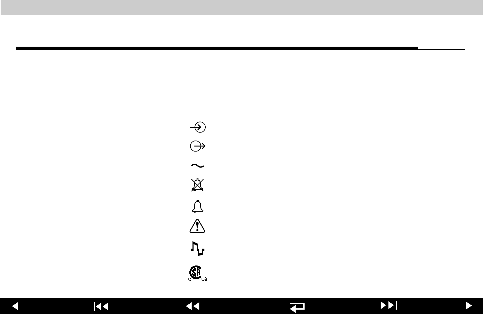
The following list includes symbols that may be used in this service
manual or on various configurations of the LIFEPAK 20 defibrillator/monitor
and accessories. Some symbols may not be relevant to your device or used in
every country.
[signal] Input
[signal] Output
ac voltage
Alarm off
Alarm on
Attention, consult accompanying documents
Biphasic defibrillator shock
Canadian Standards Association certification for Canada
and the United States
Previous Page Table of Contents Section Contents
Back
Index Next Page
Page 30
LIFEPAK 20 Defibrillator/Monitor Safety
Safety
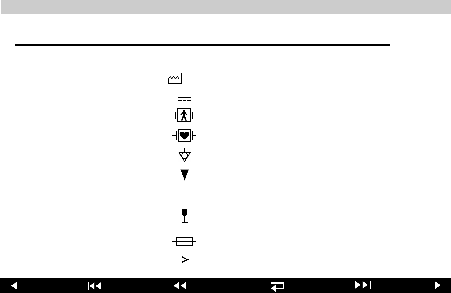
Symbols (Continued)
YYYY
!USA
2-6
Date of manufacture
DC voltage
Defibrillation protected, type BF patient connection
Defibrillation-proof type CF terminal
Equipotential connector
Event marker
For USA audiences only
Fragile/Breakable
Handle with care
Fuse
Greater than
Previous Page Table of Contents Section Contents
Back
Index Next Page
Page 31

LIFEPAK 20 Defibrillator/Monitor Safety
Safety
Symbols (Continued)
LOT
J
YYWW
Heart Rate
HOME SCREEN
Indoor use only
Joules
Less than
LIFEPAK 20 defibrillator/monitor to LIFEPAK 20
defibrillator/monitor cable
Lot number (batch code)
button
2-7
MIN
0123
Previous Page Table of Contents Section Contents
Manufacturers Item Number
Mark of conformity according to the European Medical
Device Directive 93/42/EEC
Back
Index Next Page
Page 32

LIFEPAK 20 Defibrillator/Monitor Safety
Safety
Symbols (Continued)
2-8
Negative terminal
Off (power: diconnection from the ac mains)
On (power: connection to the ac mains)
Pace arrow, internal pacing
Pace arrow, noninvasive pacing
Positive terminal
Power on/off
Protect from water
R-wave sense marker
Recognized component mark for Canada and the United
States
Previous Page Table of Contents Section Contents
Back
Index Next Page
Page 33

LIFEPAK 20 Defibrillator/Monitor Safety
Safety
Symbols (Continued)
REF
(x)
Recycle this item
Reorder number (catalog number)
Safety ground. Protective earth connection
SHOCK
Shock count (x) on screen
Single use only
Static-sensitive device (SSD)
button
2-9
Switch off
Switch on
Sync in / ECG out
Previous Page Table of Contents Section Contents
Back
Index Next Page
Page 34

LIFEPAK 20 Defibrillator/Monitor Safety
Safety
Symbols (Continued)
2-10
System connector/Data in
This end up
Turn counterclockwise to unlock
Type BF patient connection
Use by date shown: yyyy-mm-dd
VF/VT alarm on
VF/VT alarm silenced
Warning, high voltage
Previous Page Table of Contents Section Contents
Back
Index Next Page
Page 35

LIFEPAK 20 Defibrillator/Monitor Section Contents
3
Device
This section includes the following topics:
Description
Introduction
Physical Description and Features
Ordering Devices, Supplies, and Accessories
System Context Diagram
Functional Description
Previous Page Table of Contents
Back
Index Next Page
Page 36

LIFEPAK 20 Defibrillator/Monitor Device Description
Introduction
About the Device
Energy Delivery
Manual Mode
3-2
The LIFEPAK 20 defibrillator/monitor is a complete acute cardiac care response
system with both manual and semiautomatic defibrillation operation. When
clinically indicated, the LIFEPAK 20 defibrillator/monitor enables the operator to
deliver a brief, high-energy pulse of electricity to the patient’s heart. Operators
may preconfigure the device to reduce complexity during normal operation.
The LIFEPAK 20 defibrillator/monitor generates a Biphasic Truncated
Exponential (BTE) shock pulse for defibrillation. The standard method of energy
delivery is through self-adhesive QUIK-COMBO pacing/defibrillation/ECG
electrodes. When using these Disposable Defibrillation Electrodes (DDEs),
internal circuitry continuously measures the impedance between the electrodes
and allows defibrillation only when the defibrillation electrodes are attached to
the patient. The user may select from a variety of optional accessories for energy
delivery (for example, standard hard paddles or internal paddles).
In manual mode (
AED
indicator off), the device enables the operator to
MODE
Operation
Previous Page Table of Contents Section Contents
manually select an energy level, initiate a charge sequence, and apply energy in
either direct or synchronized modes. When the operator selects the
from the Alarms menu, the Continuous Patient Surveillance System (CPSS)
monitors the patient’s ECG for a shockable rhythm. A suspect rhythm
VF/VT ALARM
Back Index Next Page
Page 37

LIFEPAK 20 Defibrillator/Monitor Device Description
Introduction
AED Mode Operation
Device Primary
Functions
3-3
alerts the operator with a priority tone and screen. The operator can then follow
locally established guidelines for the administration of defibrillation therapy.
In the AED mode (
the patient’s ECG for a shockable rhythm. A suspect rhythm alerts the operator
with a priority tone and screen. The operator may continue by pressing the
ANALYZE
ECG rhythm and make recommendations. The operator can then follow locally
established guidelines for the administration of defibrillation therapy. For more
information about CPSS and SAS, see the operating instructions –
Appendix D.
The device has four primary functions:
■
button, which allows the Shock Advisory System (SAS) to analyze the
Defibrillation
– Manual or semi-automatic (AED) defibrillation
– Synchronized cardioversion in manual mode
ADVISORY
indicator on), the device uses the CPSS to monitor
– Leads off detection for therapy and ECG electrodes
■
Noninvasive Pacing
– Demand and nondemand modes of operation
Previous Page Table of Contents Section Contents
(Continued on next page)
Back Index Next Page
Page 38

LIFEPAK 20 Defibrillator/Monitor Device Description
Introduction
Device Primary
Functions (Continued)
■
Capture Patient Information
– Stores both patient and device data at each event
– Real-time clock provides time stamps for events
– Provides operator review of started events for printout
■
Patient Signal Monitoring
– Displays up to two waveforms at once
– Displays a continuous pulse oximetry (SpO2) readout
– Displays a continuous heart rate readout
– Displays waveform pace and sense markers
– Monitors for ventricular fibrillation/ventricular tachycardia and sounds
warning alarm
– Prints continuous ECG data
3-4
Service features include calibration and diagnostic functions.
Previous Page Table of Contents Section Contents
Back Index Next Page
Page 39

LIFEPAK 20 Defibrillator/Monitor Device Description
Introduction
Assemblies
The LIFEPAK 20 defibrillator/monitor consists of a three-piece case assembly
that encloses the following modules:
1. System Control Module
2. Patient Parameter Module
3. Power Module
4. Therapy Module
and the following OEM and mechanical components:
1. Display
2. Speaker
3. User Controls and Indicators
5. User Interface Module
6. OEM Module
7. System Connector Panel Module
8. Internal AC to DC Power Supply
9. Internal Battery
3-5
4. Printer
5. SpO2 Acquisition
6. Patient Connector Panel
Previous Page Table of Contents Section Contents
10. Internal Cables
(Continued on next page)
Back Index Next Page
Page 40

LIFEPAK 20 Defibrillator/Monitor Device Description
Introduction
Assemblies (Continued)
and the following Medtronic attachments:
1. ECG 3- or 5-Wire Cables
2. QUIK-COMBO Cable
3. SpO2 Cable
3-6
4. Internal Paddles
5. Sterilizable Hard Paddles
6. Standard Hard Paddles
Previous Page Table of Contents Section Contents
Back Index Next Page
Page 41

LIFEPAK 20 Defibrillator/Monitor Device Description
Physical Description and Features
Front Panel
For information about any controls, indicators, or connectors, click the
appropriate right arrow on the bar at the bottom of the screen.
1
2
3
4
5
6
28
29
27 26
3-7
25
24
23
22
21
20
19
18
17
7
8 9 10 11 15 1612 1413
Items 1–7 Items 8–14 Items 15–21 Items 22–29
Previous Page Table of Contents Section Contents
Back Index Next Page
Page 42

LIFEPAK 20 Defibrillator/Monitor Device Description
Physical Description and Features
Number Description
1 Display screen — Color Liquid Crystal Display (LCD) screen
displays operating messages, waveforms, status messages, setup
screens, and so forth.
2 Event control — Press to activate user-defined events.
3 Home Screen control — Press to return to the home screen of the
particular option or feature you are configuring. Pressing this
button does not take you to a specific screen; instead, it returns to
the home screen for the mode or event you are configuring.
4 CODE SUMMARY control — Press to print the CODE SUMMARY
critical event record.
5 Print control — Press to start and stop the printer.
6 AC Mains light — Indicates that ac power (line power) is
3-8
connected and also indicates that the battery is charging.
7 Service indicator — Lights when the device enters service error
codes into the error log (accessed through the Service Mode).
Refer to Troubleshooting for information about the error codes.
Items 8–14 Items 15–21 Items 22–29 Back to Device
Previous Page Table of Contents Section Contents
Back Index Next Page
Page 43

LIFEPAK 20 Defibrillator/Monitor Device Description
Physical Description and Features
Number Description
8 ECG cable connector — Connection point for the electrically
isolated ECG patient cable.
9 SpO2 cable connector — Connection point for the pulse oximeter.
10 IrDA port connector — Infrared connection point provides wireless
communications to data management devices (this feature is not
available with this release).
11 Speed Dial selector — When active (Speed Dial light illuminated),
turn (either direction) to make selections from the menu or overlay
shown on the screen; press to confirm your selections.
12 Speed Dial LED — Lights when selector is active.
13 Alarms control — Press to activate and silence alarms.
14 Option control — Press to access options menu.
3-9
Items 1–7 Items 15–21 Items 22–29 Back to Device
Previous Page Table of Contents Section Contents
Back Index Next Page
Page 44

LIFEPAK 20 Defibrillator/Monitor Device Description
Physical Description and Features
Number Description
15 Therapy cable connector — Connection point for the following:
– QUICK-COMBO electrodes (standard)
– FAST-PATCH electrodes (with optional cable)
– REDI PAK electrodes (optional)
– Standard adult and pediatric paddles (optional)
– External sterilizable paddles (optional)
– Internal paddles (optional)
– Posterior paddle (optional)
16 Speaker — Provides audio voice prompts and alert tones.
17 Pause control — Press to temporarily slow the pacing rate.
18 Current control — Press to adjust the pacing current.
3-10
19 Rate control — Press to select a pacing rate.
20 Pacer control — Press to activate the pacer function.
21 Sync control — Press to activate the synchronized mode.
Items 1–7 Items 8–14 Items 22–29 Back to Device
Previous Page Table of Contents Section Contents
Back Index Next Page
Page 45

LIFEPAK 20 Defibrillator/Monitor Device Description
Physical Description and Features
Number Description
22 Shock control — Press to discharge the defibrillator.
23 Charge control — Press to charge the defibrillator.
24 Energy Select control — Press to select the energy levels in
manual mode.
25 On control — Press to turn the LIFEPAK 20 defibrillator/monitor on
and off. Illuminates when defibrillator is turned on.
26 Size control — Press to change the ECG size.
27 Lead control — Press to change the ECG lead.
28 Analyze control — Press to activate the Shock Advisory System
(SAS).
29 AED mode indicator— Illuminates when defibrillator is in AED
3-11
mode.
Items 1–7 Items 8–14 Items 15–21 Back to Device
Previous Page Table of Contents Section Contents
Back Index Next Page
Page 46

LIFEPAK 20 Defibrillator/Monitor Device Description
Physical Description and Features
Side Panel
3-12
Printer—Prints ECG
waveforms, Code
summary reports, and
related information
Previous Page Table of Contents Section Contents
Printer button—Opens
printer door (for paper
installation)
Back Index Next Page
Page 47

LIFEPAK 20 Defibrillator/Monitor Device Description
Physical Description and Features
Back Panel
3-13
No. Description
1 AC power connector —
Connection point for ac
(line) power.
2 System connector —
Connection point for
RS-232 serial interface.
3 ECG/Sync connector.
4 Grounding stud.
1 432
Previous Page Table of Contents Section Contents
Back Index Next Page
Page 48

LIFEPAK 20 Defibrillator/Monitor Device Description
Physical Description and Features
What Is Shipped with a
Basic Device
(3) Rolls 50 mm
printer paper
Operating
Instructions
LIFEPAK 20 defibrillator/monitor
Operating and Servicing
Video
Warranty Card
LIFEPAK 20 defibrillator/monitor
Video Cassette
Warranty Card
A basic device includes the components shown below. For additional information
about components, see Accessories, Supplies, and Training Tools in the
LIFEPAK 20 Defibrillator/Monitor Operating Instructions – Maintaining the
Equipment.
AC Power Cord
SpO2 Sensor Pack
QUIK-COMBO
therapy cable
3-Lead ECG
cable
3-14
QUIK-COMBO
electrodes
(3-Pack) ECG
electrodes
Previous Page Table of Contents Section Contents
Back Index Next Page
Page 49

LIFEPAK 20 Defibrillator/Monitor Device Description
Ordering Devices, Supplies, and Accessories
The following table (provided for reference) summarizes optional configurations,
supplies, and accessories that are available. For ordering instructions, refer to
How to Order Parts.
Item Description Part Numbers
LIFEPAK 20 Defibrillator/Monitor
Basic Device Device with Printer. Includes:
■
Device Operating Instructions 3200750
■
Printer Paper 804700
■
Video Cassette (AED)
■
Video Cassette (Manual)
■
Power Cord 803650
■
Warranty Card 805963
3-15
3202372
3202373
■
Accessory Order Form 3202149
ECG Options
■
3-Lead ECG Cable (AHA and IEC) 3006218
■
ECG Electrodes 800139
Previous Page Table of Contents Section Contents
Back Index Next Page
Page 50

LIFEPAK 20 Defibrillator/Monitor Device Description
Ordering Devices, Supplies, and Accessories
Item Description Part Numbers
QUIK-COMBO
SpO2
5-Lead ECG
Docking Station*
* You can install the docking station on any flat surface using the installation
■
QUIK-COMBO Therapy Cables 3006570
■
REDI-PAK QUIK-COMBO Electrodes 3008497
■
QUIK-COMBO Test Plug 3201673
■
Masimo SpO2 Sensor Pack 3201655-009
■
SpO2 Cable 2.4 m (8 ft) 3201655-001
■
5-lead ECG Cable (AHA) 3200496-00
■
5-lead ECG Cable (IEC) 3200496-01
■
LIFE-PATCH ECG Electrodes 800139
■
Docking Station and Installation Template 3201551
3-16
template provided with the device. Place the template where you want to install
the docking station and use it as a guide to drill the holes for the screws that
secure the device.
Note:
Ensure that the LIFEPAK 20 defibrillator/monitor has an adequate
turning radius before installing the docking station.
Previous Page Table of Contents Section Contents
Back Index Next Page
Page 51

LIFEPAK 20 Defibrillator/Monitor Device Description
System Context Diagram
Front of Device
3-Lead ECG
Cable
(3) Rolls 50 mm
Printer Paper
5-Lead ECG
Cable
The system context diagrams below and on page 3-18 illustrate how the device
connects with external equipment, including accessories, batteries, and power
devices.
SpO2 Cable
QUIK-COMBO
Therapy Cable
(QUIK-COMBO
Electrodes)
Defibrillation Cable
(FAST-PATCH
Electrodes)
Standard Paddles
S
T
X
E
E
R
P
N
A
U
M
3-17
3-Pack ECG Electrodes
Limb Lead Attachment
QUIK-COMBO
Electrodes
Previous Page Table of Contents Section Contents
FA ST- PATC H
Electrodes
Back Index Next Page
Page 52

LIFEPAK 20 Defibrillator/Monitor Device Description
System Context Diagram
Back of Device
AC Power Cord
ECG/Sync
Connector
3-18
System Connector
Previous Page Table of Contents Section Contents
Back Index Next Page
Page 53

LIFEPAK 20 Defibrillator/Monitor Device Description
Functional Description
Introduction
The LIFEPAK 20 defibrillator/monitor is a medical device capable of combining a
variety of therapeutic and monitoring features. In addition to automatic
defibrillation, semiautomatic defibrillation, manual defibrillation, and noninvasive
pacing, the LIFEPAK 20 defibrillator/monitor offers SpO2 and ECG monitoring.
This device should be used indoors only (for example: hospital, therapy center)
and is powered by ac (line) power. There is an additional internal battery for use
as a backup to ac power.
The following functional description is intended to provide service personnel with
a basic understanding of the LIFEPAK 20 defibrillator/monitor design. Its
purpose is to assist qualified service personnel in troubleshooting to the
subassembly level. Troubleshooting below the subassembly level outside the
factory is not recommended, nor is it within the scope of this service manual to
provide the detail necessary to support such repairs.
Refer to the LIFEPAK 20 Defibrillator/Monitor System Block Diagram on the next
page as you review the descriptions that follow.
3-19
Previous Page Table of Contents Section Contents
Back Index Next Page
Page 54

LIFEPAK 20 Defibrillator/Monitor Device Description
Functional Description
Click the modules and subassemblies in the System Block Diagram below and
the System Interconnect Diagram, on the next page, to view the descriptive text.
A05 User Interface PCB A01 System Control PCB
Keypad
A11
LCD
A08
Backlight
A12
Printer
W04
Speed Dial
W03
IrDA Port
A10
SP02 PCB
A15
FPGA
A06 OEM I/F PCB
Buffe rs
CPU
Data
Bus
Power
Supply
ISO
P/S
ISO
UART
Audio
DSP
CPU
Power
Supply
A02 Patient Parameters PCB
Power
Supply
Output
Data
Bus
Data
Bus
CPU
Paddles
Pre-Amp
Companion
Chip
ECG
Pre-amp
Power
Switch
Power
Supply
A04 Therapy PCB
Data
Bus
Cap
Charger
A13 Defib
Capacitor
CPU
Power
Mux
Batte ry
Charger
CPU
Pacer
Supply
A03 Power PCB
Power
Supply
Pacer
H-Bridge
Inductor
Sonalert
Relay
A14
3-20
W02
Speaker
W01
Therapy
Connector
RS-232
Drivers
W11
ECG Out/
Syn c In
RS-232
W05 SPO2
Connector
W6 ECG
Connector
Previous Page Table of Contents Section Contents
A07
Battery
A09 AC
Power Supply
A19 EMI
Line Filter
Back Index Next Page
Page 55

LIFEPAK 20 Defibrillator/Monitor Device Description
Functional Description
System Interconnect Diagram
SpO2 Masimo PCB
IrD A
GND Stud
EOS 60W P/S
A10
J03 J01 J38 Test
J52 J53
A06
OEM PCB
P24
J24
J54 P54
P a tie n t P a ra m ete rs P C B
J03
P03
ECG
J15
P08
J08 J05
A13
Defibrillator Capacitor
P02
J02
P05
S y s te m C o n tro lle r P C B
W 07
A07
J80
P61
A09
J01
P62 P43
J02
J83 SpO 2
W 05
W25 W03
Cap D ischarge
B a tte ry
W 04
Speed Dial
W 12
A02
P06
P07
W02
A01
A14
P01
J01
A19
EM I Line Filter
J46
AC Power
W 13
P32
J32
J82 EC G
W 06
P23
J23
Speaker
Inductor/R esistor
A04
Therapy PCB
P85 J85
J33 Test
J31
P31
W18
UI Flex
P21
J21 J22
J22 J21
J01 J02
J02 J01
J11 J12
W 08 W 10 W 09
P4A
J4A
User Interface PC B
Pow er Bracket
Heatsink
PCB Bracket
Power PCB
A05
J37 J36
P37
W 17
P74
W 15
A08
B a c k lig h t
Inverter PCB
P75
W 16
P76
CN2
A11
CN1
LCD Display PCB
W19
J16 J17
P16 P17
P42 P41
A03
J13 J14
J47
J39 Test
PCB Shield
Display Bracket
J81 Therapy
W 01
P14 P13
A12
Printer
P45 J45
P47
W 11
W22 W21 W20
W24 W23
Printer Shroud
W14
P70
SYNC In
ECG Out
RS 232
3-21
J34
P34
J49
J48
Previous Page Table of Contents Section Contents
Back Index Next Page
Page 56

LIFEPAK 20 Defibrillator/Monitor Device Description
Functional Description
A01 System Control
Module
The A01 System Control module provides the central control for the LIFEPAK 20
defibrillator/monitor. A Reduced Instruction Set Computing (RISC) processor,
along with a real-time clock and digital memory, serve as the central processing
unit (CPU). A companion chip provides most of the discrete interfaces required
within the defibrillator, including the RS-232 and IrDA external communication
ports. The data bus provides high-speed communication between the system
control PCB and other PCBs within the LIFEPAK 20 defibrillator/monitor.
The following subsections discuss the major subsystems on the A01 System
Control module and their basic functions:
■
3-22
Power Supplies — The A01 System Control PCB uses SW_VBatt (switched
battery voltage) from the A04 Therapy PCB to originate five power supplies
for use throughout the PCB as follows:
– ±5 V analog power for the analog ECG out, audio output circuitry, and
bus control
– +3.3 V logic power for the processor memory, companion chip and CPU
I/O
– +2.5 V logic power for the digital signal processor
– +2.0 V logic power for the CPU processor chip
– Patient-isolated ±10 and ±5 V analog power for the paddles pre-amp
Previous Page Table of Contents Section Contents
(Continued on next page)
Back Index Next Page
Page 57

LIFEPAK 20 Defibrillator/Monitor Device Description
Functional Description
A01 System Control
Module (Continued)
■
■
■
3-23
Paddles ECG Pre-Amplifier — The paddles ECG pre-amplifier performs
patient-isolation, low-pass bandwidth filtering, and ECG sampling by means
of an analog-to-digital conversion (ADC) for the ECG signal received via the
therapy paddles. Results from the ADC are fed into the digital signal
processor (DSP) for additional filtering. Electrostatic discharge (ESD) and
defibrillation protection are provided for these signals as they pass through
the A04 Therapy PCB. Patient impedance is also measured using a 57.1 kHz
carrier and measures change in impedance (motion).
Digital Signal Processor (DSP) — The DSP completes ECG digital signal
processing to a diagnostic quality bandwidth, acceptable for SAS, heart rate
algorithm processing, and continuous ECG storage by the CPU. In addition,
the DSP provides the necessary audio processing for voice prompts and
tones, providing digital audio signals to the audio output circuitry.
Audio Output — The audio output circuitry provides digital-to-analog
conversion, filtering, and power analog drive circuitry for the audio tones and
voice prompts. Up to 2 W of amplification is provided to drive the W02
Speaker located on the defibrillator’s front case.
Previous Page Table of Contents Section Contents
Back Index Next Page
Page 58

LIFEPAK 20 Defibrillator/Monitor Device Description
Functional Description
A02 Patient Parameter
Module
The A02 Patient Parameter module collects all of the patient data (3- and 5-lead
ECG and SpO2 for the LIFEPAK 20 defibrillator/monitor), with the exception of
the paddles ECG data, and provides preprocessed data to the system controller
for AED and R-wave algorithms, alarm control, operator display and printout, and
storage. Algorithms performed on the data before it is sent to the A01 System
Control include leads off detection and internal pacer detection. A digital signal
processor (DSP) with digital memory makes up the central processing unit
(CPU) that performs these algorithms. Communication is provided to the A01
System Control PCB through the data bus.
The following subsections discuss the major subsystems on the A02 Patient
Parameter module and their basic functions:
■
3-24
Power Supplies — The A02 Patient Parameter PCB uses switched power
from the A04 Therapy module with dc power from the A07 Battery to
originate three power supply voltages for use throughout the PCB as follows:
– +3.3 V logic power to drive the CPU digital signal processor and memory
– +5 V analog power to drive the A06 OEM Interface PCB
– ±5 V patient-isolated supply to drive the ECG pre-amp
Previous Page Table of Contents Section Contents
(Continued on next page)
Back Index Next Page
Page 59

LIFEPAK 20 Defibrillator/Monitor Device Description
Functional Description
A02 Patient Parameter
Module (Continued)
A03 Power Module
■
The A03 Power module is primarily responsible for selecting the best available
source to power the rest of the PCBs in the system from the available power
sources. A microcontroller with built-in memory makes up the CPU.
Communication is provided to the A04 Therapy PCB through a serial interface.
The following subsections discuss the major subsystems on the A03 Power
module and their basic functions:
■
3-25
ECG Pre-Amplifier — The ECG pre-amplifier performs the function of
patient-isolation, low-pass bandwidth filtering, and ECG sampling through
the analog-to-digital conversion (ADC) for the ECG signal received through
the W06 ECG Connector. Digital signals are passed over the isolation barrier
into the DSP for additional signal processing.
Power Supplies — The A04 Power PCB uses ORed_VBatt (battery voltage
ORed with dc power from the A09 AC Power Supply) to originate two power
supply voltages for use throughout the PCB as follows:
– +5 V logic power to drive the CPU microcontroller and memory
– + 3.3 V analog power to drive the power pump for the RS-232 driver
circuits
Previous Page Table of Contents Section Contents
(Continued on next page)
Back Index Next Page
Page 60

LIFEPAK 20 Defibrillator/Monitor Device Description
)
Functional Description
A03 Power Module
(Continued)
■
■
3-26
Power Mux — The power mux switches battery power in and out of VBatt,
depending on power availability and load draw within the LIFEPAK 20
defibrillator/monitor. This circuit is under supervisory control of the CPU and
provides the current voltage from the A07 Battery and AC power supply to
the CPU. The circuit automatically switches from ac power to battery power,
if the voltage from the AC power supply was to rapidly fall. Low voltage is
detected by the A09 Power PCB and broadcast to the other PCBs through
the device internal communication buses.
Battery Charger —The battery charger is a constant current charger
designed specifically to support the A07 NiMH Battery selected for the
defibrillator. NiMH batteries are not designed for trickle charging, so the A09
Power PCB keeps track of the amount of time the device has been operating
from battery power. Charging is performed following high use incidents and
periodically when the batteries are not in high use. Charging can occur while
the unit is powered on or while the unit is powered off, depending on need.
The battery charger is designed to charge the internal battery usually in less
than two hours.
Previous Page Table of Contents Section Contents
(Continued on next page
Back Index Next Page
Page 61

LIFEPAK 20 Defibrillator/Monitor Device Description
Functional Description
A03 Power Module
(Continued)
■
■
3-27
Sonalert — The sonalert is an audio tone generator located on the power
PCB, that warns the user if the device is turned off while not connected to ac
power (which depletes the internal A07 Battery). Sonalert can be turned off
through the Service Configuration screens. A shipping mode is provided by
means of the Service Configuration screens to temporarily disable this
feature when packing the defibrillator for shipment.
RS-232 Drivers — The RS-232 drivers are provided to level shift the
RS-232 communications from TTL provided by the A01 System Control PCB
to the standard RS-232 ±12 V prior to leaving the device through the system
connector.
Previous Page Table of Contents Section Contents
Back Index Next Page
Page 62

LIFEPAK 20 Defibrillator/Monitor Device Description
)
Functional Description
A04 Therapy Module
The A04 Therapy module controls the pacing and defibrillation therapy features.
The primary communication between the A04 Therapy PCB and the remainder
of the defibrillator is through the data bus. A microprocessor and digital memory
make up the central processing unit (CPU) that manages communication with
the A01 System Control PCB.
The following subsections discuss the major subsystems on the A04 Therapy
module and their basic functions:
■
3-28
Power Supplies — The A04 Therapy PCB uses SW_VBatt (switched
battery voltage) from the A03 Power PCB to originate five power supply
voltages for use throughout the PCB as follows:
– +5 V logic power to drive the CPU microprocessor and memory
– ±15 V analog power for the pacing and therapy drive circuit
– Patient-isolated 5 V analog power for the pacing and therapy circuits
– Patient-isolated 15 V analog power for the pacing and therapy circuits
– Patient-isolated 30 V analog power for the pacing and therapy circuits
Previous Page Table of Contents Section Contents
(Continued on next page
Back Index Next Page
Page 63

LIFEPAK 20 Defibrillator/Monitor Device Description
Functional Description
A04 Therapy Module
(Continued)
■
■
3-29
ON
Power Switch — A power switch is a control circuit that detects the
button selection from the A05 User Interface PCB or a timer event from the
A01 System Control PCB to power up the device. This portion of the A04
Therapy PCB is powered at all times, with very low quiescent current draw.
When a power on request is detected, this circuit switches VBatt (battery
and/or ac converted dc power) provided by the A03 Power PCB to the
remaining PCBs in the device. Low Battery (Battery Fail) is detected and a
discrete signal is broadcast to other modules if battery voltage falls rapidly, or
reachs the point where normal operation is no longer feasible.
Cap Charger — The cap charger is a high-voltage, patient-isolated circuit
that charges the A13 Energy Capacitor to the correct voltage for biphasic
defibrillation (2 to 360 joules). Control is provided by the CPU, and capacitor
voltage is provided back to the CPU for feedback. The cap charger is
designed to nominally provide maximum charge rates and auto scale back to
slower charge rates when low battery voltage is detected.
■
Pacer Power Supply — The pacer power supply is a patient-isolated circuit
that charges up the A13 Energy Capacitor to the correct voltage for pacing.
Control is provided by the CPU and voltage regulation is maintained locally
within the pacer supply. Capacitor voltage is provided back to the CPU for
control through the cap charger circuitry.
Previous Page Table of Contents Section Contents
(Continued on next page)
Back Index Next Page
Page 64

LIFEPAK 20 Defibrillator/Monitor Device Description
Functional Description
A04 Therapy Module
(Continued)
■
■
■
3-30
H-Bridge — The H-Bridge is a patient-isolated circuit that creates the
biphasic defibrillation waveform. A combination of silicon controlled rectifiers
(SCR) and inuslated gate bipolor transistors (IGBT) are used to place a
positive-oriented defibrillation pulse across the patient load, followed
immediately by a negative-oriented defibrillation pulse. The defibrillation
pulse is delivered through the relay and W1 Therapy Connector to the
external therapy cable on the outside of the device.
Pacer — The pacer is a patient-isolated circuit that creates the pacing
waveform. A portion of the H-Bridge circuitry is used to support the pacer by
providing energy from the A13 Defibrillation Capacitor. A current drive is
used to control the amount of current provided to the patient during pacing.
Relay — The relay provides patient isolation from the pacing and
defibrillation circuitry when not in use. The relay is closed when the pacing
current is set above zero and stays closed until the pacing current is set back
to zero.
Previous Page Table of Contents Section Contents
Back Index Next Page
Page 65

LIFEPAK 20 Defibrillator/Monitor Device Description
)
Functional Description
A05 User Interface
Module
The A05 User Interface (UI) module is responsible for the presentation of the
acquired data to the screen display and to the printer, and for receiving all user
input. The primary communication between the UI PCB and the remainder of the
LIFEPAK 20 defibrillator/monitor is through the data bus. A RISC processor and
digital memory make up the CPU that manages communication with the A01
System Control PCB. The W18 UI Flex Cable provides physical connection
between the A05 UI PCB and the A02 Patient Parameter module.
The following subsections discuss the major subsystems on the A05 UI module
and their basic functions:
■
3-31
Power Supplies — The A05 User Interface module uses SW_VBatt
(switched battery voltage) from the A04 Therapy PCB to originate four power
supplies for use throughout the PCB as follows:
– +3.3 V logic power to drive the A11 Liquid Crystal Display (LCD) and the
A10 Printer
– +3.3 V logic power for the CPU processor and memory
– +2.5 V logic power for the field-programmable gate array
Previous Page Table of Contents Section Contents
(Continued on next page
Back Index Next Page
Page 66

LIFEPAK 20 Defibrillator/Monitor Device Description
Functional Description
A05 User Interface
Module (Continued)
■
■
3-32
Field-Programmable Gate Array (FPGA) — The Field-Programmable Gate
Array (FPGA) provides the interface between the CPU and all of the user
interface peripherals. The FPGA works in conjunction with the CPU to
provide the 1/4 VGA signals to the A11 Display, the data and strobe signals
to the A12 Printer, and drive circuitry for the keypad LEDs. The FPGA
converts the inputs from the keypad switch matrix and W4 Selector into
digital words that can be read by the CPU.
Keypad — The keypad is the primary user input control for the LIFEPAK 20
defibrillator/monitor. It consists of two parts, the keypad domes, which are
located on the rear side of the A05 UI PCB, and the elastomer keypad cover
that attaches to the front case. The keypad domes protrude through holes in
the front case and enable the keycovers to activate the domes when pressed
by the user. The user key presses are decoded by the FPGA and sent to the
ON
CPU for processing. The A05 UI PCB does not recognize the
switch. It
passes the signal to the A04 Therapy PCB.
A06 OEM and
Mechanical
The A06 OEM Interface module provides power to and collects SpO2 data from
the A10 SpO2 PCB. Its primary function is to provide patient isolation between
the SpO2 PCB and the rest of the LIFEPAK 20 defibrillator/monitor design. In
Components Module
addition, it provides physical mounting provisions for the A10 SpO2 PCB.
Previous Page Table of Contents Section Contents
(Continued on next page)
Back Index Next Page
Page 67

LIFEPAK 20 Defibrillator/Monitor Device Description
Functional Description
A06 OEM and
Mechanical
Components Module
(Continued)
A07 Battery
The following subsections discuss the major subsystems on the A06 OEM PCB
and their basic functions:
■
■
The A07 Battery is a 2.7 amp/hour, 12 V, NiMH battery that is used as an internal
backup power source when ac power is not available. This technology was
selected due to its light-weight-to-power-storage ratio and low maintenance
features. NiMH batteries require a smart, non-trickle, constant-current charge
current that is provided by the A03 Power PCB when the device is connected to
ac power. The battery wire harness interfaces directly with the A03 Power PCB.
The battery is contained within the battery well section of the bottom case. A
3-33
Power Supplies — The A06 OEM Interface PCB uses power from the A02
Patient Parameter PCB to provide the 5 V power for the A10 SpO2 PCB.
UART and ISO Buffers — The UART and ISO buffers provide patient
isolation for the serial data signals received from the A10 SpO2 PCB and
routes them to the A02 Patient Parameter PCB.
small bladed screwdriver is required to open the battery door, located on the
bottom of the LIFEPAK 20 defibrillator/monitor.
Previous Page Table of Contents Section Contents
Back Index Next Page
Page 68

LIFEPAK 20 Defibrillator/Monitor Device Description
Functional Description
A08 Backlight Inverter
A09 AC Power Supply
The A08 Backlight Inverter provides power to the internal fluorescent backlight in
A11 Active Display. Filtered SW_VBatt is provided to the A08 Backlight Inverter
through the A05 User Interface PCB. The output of the inverter is 1000–
1500 RMS, open-circuit power to the internal A11 Active Display backlight.
The A09 AC Power Supply is a 60 Watts OEM power supply, designed to meet
IEC 60601-1 standards, converting 120/240 VAC (60/50 Hz) input signals to
nominal 12 VDC. The ac power supply provides power to the A03 Power PCB for
routing to the other modules in the defibrillator. The 12 VDC output from the ac
power supply is directly diode ORed into the SW_VBatt (switched battery
voltage) to power on the A04 Therapy PCB. The A03 Power PCB sits above the
ac power supply and plugs directly into the ac power supply’s power connector.
Both the A03 Power PCB and the ac power supply are held mechanically in
place by the power assembly bracket.
3-34
Previous Page Table of Contents Section Contents
Back Index Next Page
Page 69

LIFEPAK 20 Defibrillator/Monitor Device Description
Functional Description
A10 SpO2 PCB
A11 Active Display
The A10 SpO2 PCB is a Masimo MS-5 Oximetry PCB. This patented OEM PCB
performs all functions related to oxygen saturation measurement, including
sensor drive. Measurement results are passed serially through the A06 OEM
Interface PCB to the A02 Patient Parameter PCB where the SpO2 data is
combined with the patient ECG data and sent to the A01 System Control PCB
for display processing and storage. The SpO2 PCB mounts directly to the A06
OEM Interface Board.
The A11 Active Display is a 14.5 cm (5.7”) (measured diagonally) display that
uses 1/4 VGA protocol with a 320 wide by 240 high pixel array. The display has a
protective lens held in place against the front case by a sheet metal bracket and
has an elastomeric seal. This display features full-color, high-brightness, wide
viewing angle capability and is fully visible in bright lighting situations (up to
direct sunlight operations). The A11 Active Display also contains an internal
backlight for visibility in low light situations. There is no contrast control.
3-35
A12 Printer
Previous Page Table of Contents Section Contents
The A12 Printer is a 50 mm, stepper motor-driven recorder. The printer receives
serial data and commands from the A05 User Interface PCB, converts the print
data, and controls the motor-drive signals to perform the “muscle” part of
printing. The printer returns status signals derived from the paper supply sensor
and printer door to the A05 UI PCB.
Back Index Next Page
Page 70

LIFEPAK 20 Defibrillator/Monitor Device Description
Functional Description
A13 Energy Capacitor
A14 Inductive Resistor
The A13 Energy Capacitor is a metallized film capacitor used for energy storage.
The energy capacitor stores energy for both pacing and defibrillation therapies.
The actual capacitance of the energy capacitor is calculated during the
defibrillation calibration procedure. The nominal value is 196
the capacitor is removed when the defibrillator is turned off. Energy is provided to
the A04 Therapy PCB for pacing and defibrillation therapy through the A14
Inductor Resistor. The energy capacitor mounts above the A04 Power Board by
means of a capacitor support. Wires from the energy capacitor connect directly
to the A04 Therapy PCB.
The A14 Inductive Resistor is used as an internal dump load to dissipate energy
from the A13 Energy Capacitor. Energy is removed (dumped) from the A13
Energy Capacitor when the defibrillator is turned off, and during operation when
energy remains on the capacitor for an extended period of time. The A14
Inductive Resistor provides a nominal 5 ohm load in the energy delivery path.
3-36
µ
F. The energy on
The inductor mounts to the board stack bracket. Wires from the A14 Inductive
Resistor connect directly to connectors on the A04 Therapy PCB.
Previous Page Table of Contents Section Contents
Back Index Next Page
Page 71

LIFEPAK 20 Defibrillator/Monitor Device Description
Functional Description
A15 Elastomer Keypad
A16 Bottom Case
A17 Top Case
A18 Front Case
A19 AC Input Power
Filter
The A15 Elastomer Keypad displays the common device controls (those not
available using the Speed Dial). The number of keys on this keypad varies,
depending on the features installed in a specific defibrillator.
The A16 Bottom Case is the lower shell of the defibrillator that holds the
following assemblies and connectors in position: A03 Power Module, battery,
boardstack assembly, printer assembly, therapy connector, ECG connector, IrDA
port, and SpO2 connector.
The A17 Top Case is the upper shell of the defibrillator that stores the paddles.
The A18 Front Case is the front shell of the defibrillator that holds the following
assemblies and connectors in position: display assembly, UI PCB, Speed Dial
assembly, and the speaker assembly.
The A19 AC Input Power Filter provides input current overload and
electromagnetic interference (EMI) protection for the LIFEPAK 20 defibrillator/
monitor. The filter is a potted module containing passive filter elements
3-37
(inductors and capacitors) with in-line fuses in both the line and neutral leads.
The A19 AC Input Power Filter is designed to meet the safety requirements in
IEC 60601-1.
Previous Page Table of Contents Section Contents
Back Index Next Page
Page 72

LIFEPAK 20 Defibrillator/Monitor Device Description
Functional Description
W01 Therapy
Connector
W02 Speaker
Assembly
The W01 Therapy Connector provides a patient connection point used for
delivery of either defibrillation or pacing therapeutic energies. The standard and
premium models allow the attachment of all available electrode accessories,
including QUIK-COMBO pacing/defibrillation/ECG electrodes, external hard
paddles (with built-in pediatric paddles), and internal paddles with discharge
control. The W01 Therapy Connector mounts directly to the defibrillator bottom
case and the wire harness plugs directly into the A04 Therapy PCB at J13 and
J14. The therapy connector protrudes through a hole in the defibrillator front
case to provide user access for connecting the various external cable options.
Note:
The W02 Speaker Assembly is used to deliver device tones and voice prompts,
including warnings and alarms. The OEM W02 Speaker is a small, compact,
low-profile speaker capable of producing a 1 W output with a frequency
3-38
The defibrillator supports all existing LIFEPAK 12 accessories (including
external sterilizable paddles, internal paddles, and external adult
paddles with posterior attachments).
response from 300 to 7000 Hz. The input to the speaker is from the audio power
amp in the A01 System Control PCB. The speaker is mounted directly on the
defibrillator front case and the speaker wire harness plugs into the W25 Speaker
Harness Extension Cable.
Previous Page Table of Contents Section Contents
Back Index Next Page
Page 73

LIFEPAK 20 Defibrillator/Monitor Device Description
Functional Description
W03 Infrared Data
(IrDA) Assembly (Not
active at this time)
W04 Speed Dial
Assembly
The W03 IrDA Assembly is used to provide high-speed wireless communications
to data management devices. The OEM W03 IrDA Port supports IrDA version
1.1 communications with asynchronous serial rates up to 4 Mbits/second. The
IrDA port is mounted directly on the defibrillator bottom case and the flex circuit
connects directly to the A01 System Control PCB at J08. An infrared lens is
molded into the defibrillator front case directly in front of the IrDA port. The IrDA
port and front case lens are aligned so that direct communications can easily be
made with a portable data receiver held by an operator or placed on a table.
The W04 Speed Dial Assembly is a rotary data entry device mounted on the
LIFEPAK 20 defibrillator/monitor front case. It is used to control menu access
and selection for user functions that are not supported directly by hard keys on
the keypad. The selector detects rotation, in either the clockwise or
counterclockwise direction, and presses (clicks), and passes this information on
to the A05 UI PCB at J32 for user input decoding.
3-39
W05 SpO2 Assembly
Previous Page Table of Contents Section Contents
The W05 SpO2 Assembly provides a connecting point for the external SpO2
cable. The SpO2 connector is mounted on the LIFEPAK 20 defibrillator/monitor
bottom case and the flex circuit connects directly to the A10 SpO2 PCB.
Back Index Next Page
Page 74

LIFEPAK 20 Defibrillator/Monitor Device Description
Functional Description
W06 ECG Connector
W07 Capacitor
Discharge Cable
W08 Battery Cable
W09 – W10 Power to
Therapy PCB Cables
The W06 ECG connector provides a connection point for the standard 3- and 5lead patient ECG cables. The ECG connector is mounted on the LIFEPAK 20
defibrillator/monitor bottom case and the attached wire harness connects directly
with the A05 Patient Parameters PCB at J23. The ECG connector is also
compatible with the LIFEPAK 12 3-wire or 4-wire patient ECG cables.
The W07 Capacitor Discharge Cable provides a capacitor discharge point by
connecting to the A04 Therapy PCB at pin 5 of J02.
The W08 Battery Cable connects the A07 Battery to the A03 Power PCB. The
cable is hardwired to the A03 Power PCB and the other end connects to the A07
battery at at J85.
The W09–W10 Power to Therapy PCB Cables connect the A03 Power PCB to
the A04 Therapy PCB. W09 is a replaceable cable that connects on the A04
Therapy PCB at J16 and the A03 Power PCB at J41. W10 is hardwired to the
3-40
A03 Power PCB and connects to the A04 Therapy PCB at J17.
Previous Page Table of Contents Section Contents
Back Index Next Page
Page 75

LIFEPAK 20 Defibrillator/Monitor Device Description
Functional Description
W11 ECG Sync/System
Cable
W12 Grounding Cable
W13 AC Power Cable
W14 Printer Cable
W15 LCD to UI PCB
Cable
W16 LCD to Backlight
Cable
The W11 ECG Sync/System Cables connect the ECG Sync connector and the
system connector to the A03 Power PCB at J47.
The W12 Grounding Cable provides a grounding path for the Speed Dial.
The W13 AC Power Cable connects the A09 Power Supply at J02 with the A03
Power PCB (hardwired connection).
The W14 Printer Cable connects the A05 UI PCB at J34 with the A03 Power
PCB at J45 and the A12 Printer.
The W15 LCB to UI PCB Cable connects the A11 LCD Display PCB at CN1 with
the A05 UI PCB at J36.
The W16 LCD to Backlight Cable connects the A11 LCD Display PCB at P77 to
the A08 Backlight Inverter PCB at CN2.
3-41
W17 Backlight to User
Interface PCB Cable
Previous Page Table of Contents Section Contents
The W17 Backlight to UI PCB Cable connects the A08 Backlight Inverter PCB at
P74 to the A05 UI PCB at J37.
Back Index Next Page
Page 76

LIFEPAK 20 Defibrillator/Monitor Device Description
Functional Description
W18 UI Flex Cable
W19 – W24 Grounding
Cables
W25 Speaker Harness
Extension Cable
The W18 UI Flex Cable connects the A02 Patient Parameters PCB at J21 and
J22 to the UI PCB at J31.
The W19 through W24 Grounding Cables provide grounding paths for various
device components.
The W25 Speaker Harness Extension Cable connects the W02 Speaker
Assembly to the A01 System PCB at J5.
3-42
Previous Page Table of Contents Section Contents
Back Index Next Page
Page 77

LIFEPAK 20 Defibrillator/Monitor Operating Instructions
4
Operating Instructions
The LIFEPAK 20 Defibrillator/Monitor Operating Instructions familiarize the
operator with basic device functions and identify controls, indicators, and
connectors. Qualified service personnel must consult both the
LIFEPAK 20 Defibrillator/Monitor Operating Instructions and this service manual
for a complete understanding of the use and maintenance of the device.
WARNINGS!
Possible improper device performance.
or FAST-PATCH electrodes and batteries described in this Service Manual.
Substitution of non-Medtronic electrodes or batteries may cause the
device to operate improperly.
Possible loss of power during patient care. Using improperly maintained
batteries to power the LIFEPAK 20 defibrillator/monitor may cause
premature power loss.
Use only Medtronic QUIK-COMBO
Previous Page Table of Contents
Back
Index Next Page
Page 78

LIFEPAK 20 Defibrillator/Monitor Operating Instructions
Operating Instructions
Use the following links to the LIFEPAK 20 Defibrillator/Monitor Operating
Instructions for operating procedures and related information.
■
■
4-2
Preface
– About Automated External Defibrillation
– About Defibrillation Therapy
– About Noninvasive Pacing
– About SpO2 Monitoring
Safety Information
– Te r ms
– General Warnings and Cautions
– Symbols
Previous Page Table of Contents
Back
Index Next Page
Page 79

LIFEPAK 20 Defibrillator/Monitor Operating Instructions
Operating Instructions
■
■
■
4-3
Basic Orientation
– Introduction
– Unpacking and Inspecting
– Controls, Indicators, and Connectors
– Entering Patient Data
– Setting Alarms
– Managing Alarms
– Connecting to Power
Monitoring
– Monitoring the ECG
– Monitoring SpO2
Therapy
– General Therapy Warnings and Cautions
– Therapy Electrode and Standard Paddle Placement
– Automated External Defibrillation
– Manual Defibrillation
– Pediatric Defibrillation
– Noninvasive Pacing
Previous Page Table of Contents
Back
Index Next Page
Page 80

LIFEPAK 20 Defibrillator/Monitor Operating Instructions
Operating Instructions
■
■
4-4
Paddle Accessory Options
– Therapy Electrodes
– Standard Paddle Set (Optional)
– Posterior Defibrillation Paddle (PN 802461)
– External Sterilizable Paddles (PN 3009166)
– Internal Handles with Discharge Control (PN 3010901)
– Cleaning and Sterilization Guidelines
Data Management
– Overview of Data Storage and Retrieval
– CODE SUMMARY Report
– Managing Archived Patient Records
– Entering Archives Mode
– Printing Archived Patient Records
– Editing Archived Patient Records
– Deleting Archived Patient Records
Previous Page Table of Contents
Back
Index Next Page
Page 81

LIFEPAK 20 Defibrillator/Monitor Operating Instructions
Operating Instructions
■
4-5
Maintaining the Equipment
– General Maintenance and Testing
– General Troubleshooting Tips
– Service and Repair
– Product Recycling Information
– Warranty
– Accessories, Supplies, and Training Tools
Previous Page Table of Contents
Back
Index Next Page
Page 82

LIFEPAK 20 Defibrillator/Monitor Operating Instructions
Operating Instructions
■
4-6
Defining Setup Options
– Setup Options
– Entering Setup Options
– General Setup Menu
– Manual Mode Setup Menu
– AED Mode Setup Menu
– Pacing Setup Menu
– Monitoring Menu
– Events Setup Menu
– Alarms Setup Menu
– Printer Setup Menu
– Clock Setup Menu
– Reset Defaults Setup Menu
– Print Defaults
– Send Configuration Setup Menu
– Set Passcode Setup Menu
– Service Mode
Previous Page Table of Contents
Back
Index Next Page
Page 83

LIFEPAK 20 Defibrillator/Monitor Operating Instructions
Operating Instructions
■
■
■
■
■
■
■
4-7
Appendix A Specifications and Performance Characteristics
Appendix B Clinical Summaries
Appendix C Screen Messages
Appendix D Operator’s Checklist
Appendix E Shock Advisory System
Appendix F Docking Station
Appendix G Declaration of Conformity
Previous Page Table of Contents
Back
Index Next Page
Page 84

LIFEPAK 20 Defibrillator/Monitor Section Contents
5
Modes of Operation
When the LIFEPAK 20 defibrillator/monitor is turned on, it always operates in
one of five modes. Choose from the following links to learn more about a
particular operating mode.
Manual Mode
AED Mode
Setup Mode
Inservice Mode
Service Mode
Previous Page Table of Contents
Back
Index Next Page
Page 85

LIFEPAK 20 Defibrillator/Monitor Modes of Operation
Manual Mode
Manual Mode
Turning On the
Defibrillator in Manual
Mode
5-2
Manual mode enables the user to determine when to deliver a shock.
The LIFEPAK 20 defibrillator/monitor can be configured to turn on in manual
mode by selecting
option. The following table shows all the defibrillator’s available turn on options.
Mode/Response Response Description
Manual/Direct Turns on in manual; direct access between AED and
AED/Direct Turns on in AED; direct access between AED and
AED/Confirm Turns on in AED; operator confirms manual mode
AED/Passcode Turns on in AED; operator enters manual mode
SETUP/MANUAL ACCESS
manual modes.
manual modes.
selection, Yes/No.
passcode.
and selecting the
MANUAL/DIRECT
Once the defibrillator/monitor has been placed in manual mode and reset to AED
mode using the
reprompts or passcode requests until the defibrillator power has been cycled.
For a complete description of the setup options, refer to the operating
instructions – Defining Setup Options.
Previous Page Table of Contents Section Contents
ANALYZE
button, there will be no additional manual mode
Back
Index Next Page
Page 86

LIFEPAK 20 Defibrillator/Monitor Modes of Operation
Manual Mode
Starting Manual Mode
from AED Mode
5-3
If the AED mode indicator is illuminated when the defibrillator is powered on, the
defibrillator is in AED Mode. To enter manual mode:
■
Open the door (if attached to the defibrillator)
-OR-
■
Select one of the following buttons:
ENERGY SELECT
CHARGE
PACER
LEAD
There are no intervening steps when going from manual mode to AED mode.
Note: Closing the door when in manual mode does not restart AED mode
operation. To restart AED mode, press the
ANALYZE
button or cycle the
defibrillator power.
Previous Page Table of Contents Section Contents
Back
Index Next Page
Page 87

LIFEPAK 20 Defibrillator/Monitor Modes of Operation
AED Mode
AED Mode
5-4
In automated external defibrillator (AED) mode, the defibrillator automatically
evaluates the patient rhythm to determine if a shock is needed and prompts the
user to deliver a shock by pressing the
You can configure your LIFEPAK 20 defibrillator/monitor to turn on in manual
mode by selecting
desired option. The default setting for the LIFEPAK 20 defibrillator/monitor is to
turn on in AED mode.
Set options for AED mode by entering the Setup screen and selecting AED
mode. AED mode options include energy protocol, voice prompts, ECG display,
CPR time, and others. For a complete description of the options available, refer
to the operating instructions – Defining Setup Options.
Note: If configured to turn on in AED mode, opening the door on the LIFEPAK
20 defibrillator/monitor turns off AED mode and places the defibrillator in
manual mode. Closing the door does not restart AED mode operation.
To restart AED mode, press the
MANUAL ACCESS
SHOCK
from the Setup screen and activating the
ADVISORY
button.
button or cycle the defibrillator
power.
Previous Page Table of Contents Section Contents
Back
Index Next Page
Page 88

LIFEPAK 20 Defibrillator/Monitor Modes of Operation
(C
)
Setup Mode
Setup Mode
Saving the Setup
Configuration
5-5
The operating defaults for the defibrillator are configured while you are in setup
mode. Options include manual mode and AED mode operating characteristics,
alarms setup, time-of-day clock, and others. After the setup is complete, turn off
the device to save the configuration. The next time the device is turned on, the
operating defaults last selected will be active.
The information that follows, with references to the operating instructions, shows
the options available in the setup mode. There is also a factory reset option that
resets the device to the factory default settings except the maintenance interval,
which remain unchanged.
If the defibrillator owner has a setup configuration that cannot be disturbed, two
choices are available to preserve this setup. The first method is to print the
setup configuration. When service is complete, you can verify the setup and
then manually reset the configuration.
The second method is to transfer the setup configuration to another
LIFEPAK 20 defibrillator/monitor. After service is complete, transfer the
configuration back to the device.
Previous Page Table of Contents Section Contents
Back
ontinued on next page
Index Next Page
Page 89

LIFEPAK 20 Defibrillator/Monitor Modes of Operation
(C
)
Setup Mode
Saving the Setup
Configuration
(Continued)
Creating a Passcode
5-6
Note: Saving the configuration using the Transfer and Save Setup Procedures
requires that both of the devices have the same software version.
Otherwise, unexpected results may occur once the configuration has
been restored to the repaired device.
To create a passcode:
1. Hold down the
these buttons until the Enter Passcode screen appears. The Speed Dial LED
illuminates indicating that the Speed Dial is active.
2. Enter the factory default passcode (0000) or the reserved technician
passcode (5433 or LIFE) to gain access to the Setup screen. Use the Speed
Dial to scroll through the digits in the highlighted fields. Select numbers by
pressing the Speed Dial. As a number is selected, it changes to an asterisk
for passcode protection and the next digit in line highlights.
OPTIONS
and
EVENT
buttons and press the ON button. Hold
3. When you have entered the passcode, press the Speed Dial. The Setup
screen appears. The
incorrect passcode is entered.
Previous Page Table of Contents Section Contents
PASSCODE INCORRECT-TRY AGAIN
Back
message appears if an
ontinued on next page
Index Next Page
Page 90

LIFEPAK 20 Defibrillator/Monitor Modes of Operation
(C
)
Setup Mode
Creating a Passcode
(continued)
4. Select
appears. The following table defines the options in the Set Passcodes
screen.
Option Description
Setup Mode Set passcode to enter setup mode
Archives Access* Select a passcode access protocol for archives mode:
Archives Mode Set passcode to enter archives mode
Delete Records Set passcode to delete records in archives mode
* Set the defibrillator to any of the following protocols:
1. Allow unlimited access to archives mode and allow records to be deleted.
SET PASSCODES
1. No Passcode (default)
2. Archives Only
from the Setup menu. The Set Passcodes screen
3. Delete Only
4. Archive/Delete
5-7
2. Require a password to enter archives mode, but allow records to be deleted.
3. Allow unlimited access to archives mode, but require a password to delete records.
4. Require a password to enter archives mode and delete records.
Previous Page Table of Contents Section Contents
Back
ontinued on next page
Index Next Page
Page 91

LIFEPAK 20 Defibrillator/Monitor Modes of Operation
Setup Mode
Creating a Passcode
(continued)
5-8
5. If defining an access protocol, select one of the archives access protocols
and return to the previous screen.
-ORIf setting a passcode, select the desired option. The Enter Passcode screen
appears and the first digit in the display is highlighted.
6. Enter the desired passcode.
7. After all numbers have been entered, press the Speed Dial to accept the new
passcode.
Previous Page Table of Contents Section Contents
Back
Index Next Page
Page 92

LIFEPAK 20 Defibrillator/Monitor Modes of Operation
(C
)
Setup Mode
Entering Setup Mode
5-9
To enter setup mode:
1. Hold down the
these buttons until the Enter Passcode screen appears. The Speed Dial LED
illuminates indicating that the Speed Dial is active.
2. Enter the passcode by rotating the Speed Dial to select a number and then
pressing the Speed Dial. As a number is selected, it changes to an asterisk
for passcode protection and the next digit in line highlights.
Note: The factory default passcode (0000) and the reserved technician
passcode (5433 or LIFE) may be used in place of other passcodes to
gain access to the Setup and Service screens.
3. When you have entered the passcode, press the Speed Dial. The Setup
screen appears. The
incorrect passcode is entered.
OPTIONS
PASSCODE INCORRECT-TRY AGAIN
and
EVENT
buttons and press the ON button. Hold
message appears if an
Previous Page Table of Contents Section Contents
Back
ontinued on next page
Index Next Page
Page 93

LIFEPAK 20 Defibrillator/Monitor Modes of Operation
(C
)
Setup Mode
Entering Setup Mode
(continued)
5-10
The following table defines the Setup screen option.
Note: Refer to the LIFEPAK 20 Defibrillator/Monitor Operating Instructions
for compete descriptions of all options.
Option Description
General Set up general device options
Manual Mode Set up manual mode defaults
AED Mode Set up AED mode defaults
Pacing Set up pacing defaults
Monitoring Set up monitoring defaults
Events Set up items to appear on the event screen
Alarms Set up alarms defaults
Printer Set up printer defaults
Clock Set up date and time default
Reset Defaults Reset all defaults to factory configuration settings
Previous Page Table of Contents Section Contents
Back
ontinued on next page
Index Next Page
Page 94

LIFEPAK 20 Defibrillator/Monitor Modes of Operation
Setup Mode
Entering Setup Mode
(continued)
5-11
Option Description
Print Defaults Print a report of current configuration settings
Send Config Send device configuration to another device
Set Passcode Set passcodes for setup mode and archives mode
Service Go to the service mode screens
Turn off the deffibrillator to exit setup mode.
Previous Page Table of Contents Section Contents
Back
Index Next Page
Page 95

LIFEPAK 20 Defibrillator/Monitor Modes of Operation
Inservice Mode
Inservice Mode
Entering Inservice
Mode
5-12
Inservice mode enables users to practice or demonstrate the monitoring
functions of the LIFEPAK 20 defibrillator/monitor. The functions include:
■
ECG lead selection, size, volume, and moving ECG waveform with heart rate
■
SpO2
■
Alarms
■
Events
Note: No therapy features are available in the inservice mode.
To enter inservice mode:
1. Remove all cables from the defibrillator. Inservice mode cannot be entered if
cables are attached to the device.
2. Turn on the device while holding down the
these controls down until the Inservice screen appears.
HOME
and
EVENT
buttons. Hold
Turn off the defibrillator to exit inservice mode.
Previous Page Table of Contents Section Contents
Back
Index Next Page
Page 96

LIFEPAK 20 Defibrillator/Monitor Modes of Operation
Service Mode
Service Mode
The service mode functions enable qualified service personnel to:
Function Description
*Perform device
calibration routines
*Perform device tests
View the device status
registers
■
Defibrillation
Calibration
■
Keypad Test
■
Pixels Test
■
Device Log Status
■
Service Log Status
■
Device Data
■
Printer Test
■
Audio Test
■
Counters Status
■
Clear Memory
Set the service mode passcode
Set the maintenance prompt interval
5-13
Reset the maintenance prompt interval
* The Performance Inspection Procedure must be performed from start to finish
in the order presented.
Previous Page Table of Contents Section Contents
Back
Index Next Page
Page 97

LIFEPAK 20 Defibrillator/Monitor Modes of Operation
(C
)
Service Mode
Entering Service Mode
5-14
Service personnel may enter the Service screen by:
■
Selecting
■
At the Setup Passcode screen, enter the service passcode.
To enter service mode by selecting
1. Hold down the
SERVICE
OPTIONS
from the Setup screen.
and
SERVICE
EVENT
buttons and press the ON button. Hold
from the Setup screen:
these buttons until the Enter Passcode screen appears. The Speed Dial LED
illuminates indicating that the Speed Dial is active.
2. Enter the passcode by rotating the Speed Dial to select a number and then
pressing the Speed Dial. As a number is selected, it changes to an asterisk
for passcode protection and the next digit in line highlights.
Note: The factory default passcode (0000) and the reserved technician
passcode (5433 or LIFE) may be used in place of other passcodes to
gain access to the Setup and Service screens.
3. When you have entered the passcode, press the Speed Dial. The Setup
screen appears. The
PASSCODE INCORRECT-TRY AGAIN
incorrect passcode is entered.
Previous Page Table of Contents Section Contents
Back
message appears, if an
ontinued on next page
Index Next Page
Page 98

LIFEPAK 20 Defibrillator/Monitor Modes of Operation
Service Mode
Entering Service Mode
(Continued)
4. Select
appears.
5. Enter the service passcode.
6. After you enter the passcode, press the Speed Dial. The Service screen
appears. The
incorrect passcode is entered.
The Service screen options include:
Option Description
Defib Cal
Tests
Status
SERVICE
from the Setup screen. The Service Passcode screen
PASSCODE INCORRECT-TRY AGAIN
Perform Test and Calibration Procedure
Perform Performance Inspection Procedure
Display device status
message appears, if an
5-15
Set Passcode
Maint Prompt
Setup Return to main Setup screen
Power the unit off to exit service mode.
Previous Page Table of Contents Section Contents
Set the service mode access passcode
Prompt user to perform preventative maintenance
Back
Index Next Page
Page 99

LIFEPAK 20 Defibrillator/Monitor Modes of Operation
Service Mode
Setting the Service
Mode Passcode
5-16
To set the service mode passcode:
1. Select the
Passcode screen appears.
2. Enter the passcode by rotating the Speed Dial to select a number and then
pressing the Speed Dial. As a number is selected, it changes to an asterisk
for passcode protection and the next digit in line highlights.
3. When the last digit is entered, the Service screen appears.
SET PASSCODE
button from the Service screen. The Service/Set
Previous Page Table of Contents Section Contents
Back
Index Next Page
Page 100

LIFEPAK 20 Defibrillator/Monitor Modes of Operation
Service Mode
Setting the
Maintenance Prompt
Interval
5-17
The LIFEPAK 20 defibrillator/monitor can be set to display a screen message
that alerts the user when the maintenance prompt interval date has passed. The
screen message
after the device is powered on. The defibrillator maintenance interval can be
turned off or set to 3 months, 6 months or 12 months; the factory default is
but it can be activated by service personnel.
Note: To turn off the
interval, complete the Resetting the Maintenance Prompt Interval
procedure on the next page.
To change the scheduled maintenance interval:
1. Enter service mode.
2. From the Service menu, select the
SERVICE/MAINT PROMPT
MAINTENANCE DUE
MAINTENANCE DUE
menu, including the next prompt date for scheduled
appears on the screen for the first 10 minutes
OFF,
message or reset the maintenance
MAINT PROMPT
button to display the
maintenance.
3. Select
MONTHS
4. Select the desired interval.
5. Turn off the defibrillator.
Previous Page Table of Contents Section Contents
INTERVAL
appear.
. The interval choices of
OFF, 3 MONTHS, 6 MONTHS
Back
Index Next Page
, and
12
 Loading...