

Page 1
Title: Defibrillator – Lifepak 12 Date: January 11, 2020
By: Physio-Control / Medtronic *
File = Lifepak 12 Guide.doc
DISCLAIMER: THIS PROCEDURE PROVIDED "AS IS" AND
WITH POSSIBLE FAULTS. USER MUST VERIFY BEFORE
USE. NEITHER PROVIDER NOR WEBSITE ASSUMES ANY
RESPONSIBILITY FOR ITS USE.
1. General
Service Guideline for:
Medtronic/PhysioControl Lifepak 12
Defibrillator with ECG, SP02, NIBP and CO2 monitoring.
2. Reference Documents
Lifepak 12 Service Manual PN 3010013-015
Lifepak 12 Operating Instructions PN 3010012
3. Accessories
Hard Paddles / Cable, Soft Paddles / Cable
ECG clips with Cable, Printer Paper
SP02 Sensor/Cable (Massimo and Nellcor supported)
CO2 Sensor/Cable (not common)
NIBP Cuff/Tubing
Power Adapter (VLP12-06-000076) / Batteries
Lifepak 500 Test Load (optional but convenient)
Note: Section 8 in the OPERATING INSTRUCTIONS provides an official check of the unit as an option for
most of the following.
4. Basic PM Procedure
4.1. Physical Inspection – check paddles, case & cord integrity, tubing for cracks, and battery age.
Mild soap or disinfectant suggested for external cleaning. Do not use bleach or a flammable
liquid. If internal cleaning is needed, low pressure compressed air can be used.
Note: When configured mainly for portable use, traditional hand paddles may not be included.
4.2. Turn On and User Test
Plug in unit. When connected to the AC charger, but before turn-on, the “Batt Chg” LED
will light as long as the unit has a usable battery.
Turn ON. Press <OPTIONS>. Use the Selector Dial to choose User Test, which
automatically performs these tasks in less than a minute:
• Performs self-tests
• Charges to 10J and discharges internally (this energy is not accessible at the therapy
connector)
• Prints a Pass/Fail report
If display shows “Maintenance Due”, see Appendix.
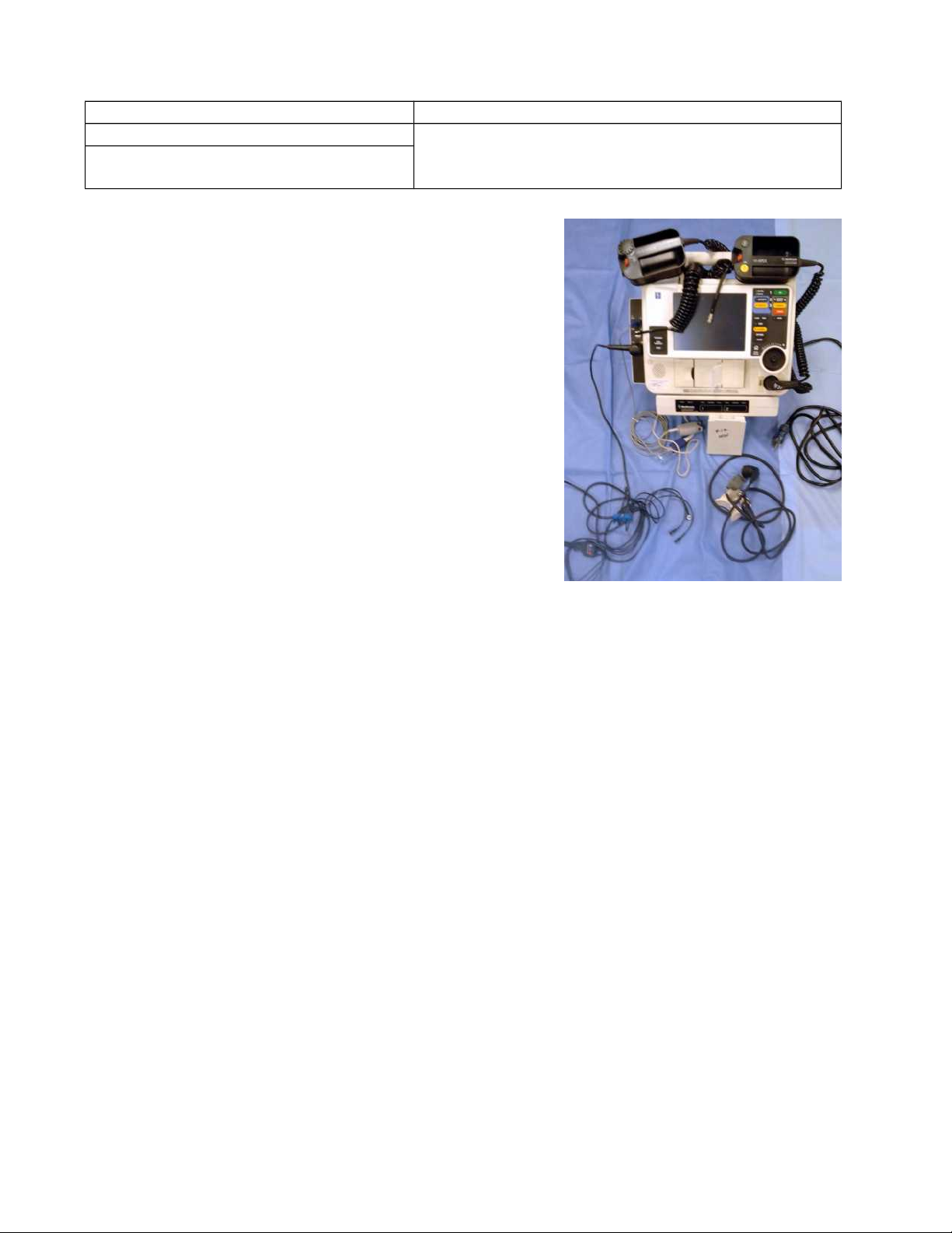
4.3. Main Battery Quality / Power Adapter (see picture above, and Appendix for mounting options)
The Power Adapter’s display will indicate one of these: “READY”, “CHARGING”, or
“FAILED”, unless battery missing or open. See Appendix for more info.
Page 2

With main batteries removed, confirm the defibrillator powers on without the SERVICE
LED illuminated.
Note: The typical battery pair for this unit is Nicad. These batteries, if left uncharged for several months, can
eventually self-short-out due to the growth of conductive crystals which otherwise burn away in a charged
battery. And if supplied with sealed lead acid batteries, these can completely open up after several years, and
will not be detected by the smart charger. The main unit can be used without batteries.
4.4. ECG Results
Connect a 3-lead ECG wire set to the EKG or defib simulator, matching colors or
designators. (This unit also supports 4, 5 and 12 lead.) An ECG waveform will appear on
the defibrillator. If not, use the <LEAD > button. Next, check the waveform “SIZE” button.
Change QRS volume by using the rotary selector to highlight the display’s upper left corner.
Press the rotary selector to bring up the QRS volume graphic. Volume can be changed from
zero to loud in several bar graph steps.
4.5. Strip Chart
With the waveform still on display, press <PRINT> and verify the printer waveform. Press
it again to stop printing. Note the date and time in the margin of the paper. See Appendix
for sample printout.
4.6. Joule Test (Paddles).
Note: To lessen paper waste, open the printer door to the right and mechanism will temporarily disengage.
Press SYNC. Confirm the SYNC LED lights. Adjust ECG size until the sense markers
appear on the QRS complexes. Confirm that the SYNC LED blinks off with each detected
QRS complex and the heart rate is displayed.
Note: “Therapy cable” refers to the standard high voltage cable that connects to patient pads or
paddles.
If available, connect the Lifepak 500 test load in lieu of paddles. Select 200 joules. Press
CHARGE and confirm that the tone indicating full charge sounds within 10 seconds or less.
Then press <SHOCK>. Test successful if display shows “Energy Delivered”.
If using a conventional defib testor (joule meter), place the standard paddles on the
defibrillator-checker paddle plates, and simultaneously press and hold both discharge buttons
while observing the screen. Confirm the defibrillator discharges on the next sensed QRS
complex. Warning: hand paddles that have not been used for a while may not respond on the
first button press.
4.7. NIBP Check (only if present).
Select the appropriately sized cuff. Typical initial simulator settings are 120/80. Press
<NIBP> to start the measurement. Results in the lower left screen corner. Next, change the
simulator for high blood pressure, and check. See Table 3-8 in the Operating Instructions for
an error list. Expected tracking accuracy: tbd
4.8. SP02 Check
Page 3

To conserve battery power, the pulse oximeter goes into “sleep mode” when not in use.
When a good sensor is connected, note its internal red LED. After approximately 20
seconds using a healthy subject, the display should read between 91 and 99. A waveform
normally is not displayed.
4.9. CO2 Check (if supplied – not common)
APPENDIX
Power Adapter Placement (see photo to the right)
If the unit is used mainly for non-portable service, it has four mounting holes
to permanently mount the power adapter to the bottom of the
defibrillator/monitor using 8-32 x 1 ¾” screws. Refer to Figure 7-5 of the
Operating Instructions if necessary. Otherwise, for stationary units, this
power-pack as standalone connects to the unit via a ~1 foot extension cable.
Main Batteries This unit can use nicad or sealed lead acid batteries (at least
one). Some battery versions come with an LED display which shows charge capacity. Nicad batteries lose
almost 1% of their capacity per day; sealed lead acid (SLA) lose only 0.1%. A review of several Lifepak
12’s indicates that the SLA batteries may last only 2 years, but nicads at a much lower cost will usually last
considerably longer; the drawbacks: proper disposal, and avoiding extended periods of discharge.
Internal Memory Battery The internal coin cell battery (type 2032) requires replacement every 5
years, and immediately if time and date will not hold. See …
“http://www.frankshospitalworkshop.com/equipment/documents/defibrillators/service_manuals/Medtronic
%20Lifepak%2012%20-%20Coin-cell%20battery%20replacement.pdf” or p.351 Service Manual.
Sales and Service Even though the Lifepak 12 is no longer supported by the current corporate owner
(Stryker), there are 3rd party medical repair organizations that do.
Page 4

Disabling or Resetting the Maintenance Due Indicator
Enter the SERVICE MODE: 1. Hold down both the OPTIONS and EVENT keys, then turn on the device.
Continue holding until the SETUP Passcode screen overlay appears.
2. The factory default is 0000; the reserved technician passcode is 5433. To enter the passcode, rotate the
Selector to select a digit, then press the Selector to continue. After the last digit is entered, the SETUP menu
appears. 3. Select the MAINT PROMPT… menu option.
4. Select INTERVAL, and choose OFF to disable the maintenance prompt. If a
maintenance prompt is desired, Select INTERVAL, and make the appropriate
selection. The maintenance interval timer resets to the selected interval. 5. Turn the unit off.
Patient Leakage Test / Line Leakage Test
Refer to the leakage testor’s manual for specific directions.
PIP – Instructions (Electrical Leakage Current) begin on page 59 of the Lifepak 12 Service manual.
Should be done if unit is dropped/damaged or incurred moisture.
Portable Mode – pouches only Stationary Configuration Connecting Power Pack
 Loading...