


KAPPA®400 SERIES AND DX2
PACEMAKERS
Software Model 9952 2.0
Vision™ Programmer Software
Volume I, Pacemaker Programming Guide


Medtronic.Kappa® 400 Series
Pacemaker Information and
Programming Guide
Volume I - Pacemaker Programming
Guide
A Guide to Using the
9790 Series Programmer
with Medtronic.Kappa
K
401, KDR403,
DR
KSR401, KSR403,
Pacemakers
®
This guide also applies to
Medtronic® DX2 7970 and 7972
pacemakers as described in
Section I at the back of Volume II.
Caution: Federal law (USA)
restricts this device to sale by
or on the order of a physician.
6
4

Checklist, Fast Path, Kappa, Marker Channel, Medtronic, Medtronic.Kappa, Medtronic.Vision, Quick Look,
Rate Profile Optimization, Remote Assistant, Significant Events, Sinus Preference, and Vision are all trademarks
of Medtronic, Inc.
5

How to Use This Guide
Information is Contained in Two Volumes
Product information about Medtronic.Kappa® 400 Series
pacemakers and Medtronic.Vision™ software is presented in two
volumes.
Vol um e I -- Contains information about using the programmer.
This volume is made up of Chapters 1 through 9.
Vol um e I I -- Contains pacemaker information and includes
Chapters 10 through 18 and Sections A through J. Section I
includes information on using Volumes I and II with Medtronic®
DX2 pacemaker models.
About Volume I
Volume I presents the following information about using the 9790
programmer.
How to Use This Guide
■
How to setup and configure the programmer and access online help.
■
How to start a patient session, use the various follow-up
features during the session, and properly end the session.
■
How to use Checklist to streamline a follow-up session.
■
How to view and print the patient’s ECG and EGM waveform
traces.
■
How to set the pacemaker up to collect diagnostic data and
how to retrieve and view this information.
■
How to measure stimulation thresholds and sensing levels.
■
How to program parameter values, initialize the MV sensor,
and verify rate response parameters settings.
Medtronic.Kappa® 400 Series Pacemaker Programming Guide iii
6

How to Use This Guide
About Volume II
Volume II describes how the pacemaker operates and specifies the
capabilities of each model.
■
Chapters 10 through 17 describe the pacing modes, rate
response options, special therapy features, telemetry types,
and data collection options. In some cases, guidelines are
given on how to configure the pacemaker operation.
■
Chapter 18 contains troubleshooting information for electrical
and hemodynamic problems.
■
Sections A through E specify parameter and data collection
capabilities, longevity projections, and mechanical and
electrical specifications.
■
Sections F through H provide general warning and cautions,
potential interference sources, and general indications for
pacing.
■
Section I is a special supplement covering use of Volumes I
and II with Medtronic® DX2 pacemaker models.
■
Section J contains a glossary of terms.
iv Medtronic.Kappa® 400 Series Pacemaker Programming Guide
7

Table of Contents
How to Use This Guide iii
1. Programmer Basics
Setting Up the 9790 Programmer 1-2
Connecting the Programmer to Skin Electrodes 1-4
Positioning and Using the Programming Head 1-5
About the Display Screen 1-8
Programming Emergency Parameters 1-15
Recording an ECG Strip 1-16
Using the On-line Help Feature 1-19
2. Conducting a Patient Session
Important Reminders About
Medtronic.Kappa® 400 Series Pacemakers 2-2
Starting a Patient Session 2-5
Proceeding with Task Selection 2-9
Interrogating the Pacemaker 2-11
Taking a Quick Look at Pacemaker Operation 2-12
Viewing Battery and Lead Measurements 2-16
Checking the Present Parameter Settings 2-19
Viewing Patient Information Stored in the Pacemaker 2-21
Recording an ECG Strip of Magnet Operation 2-22
Checking the Patient’s Underlying Rhythm 2-25
Printing Data Reports 2-28
Ending a Patient Session 2-33
Tab le of Co nt en ts
3. Streamlining Follow-up with Checklist
About the Checklist Feature 3-2
Using Checklist to Streamline a Follow-up Session 3-3
Creating a Custom Checklist 3-6
4. Viewing the Patient’s ECG and EGM Traces
Viewing the ECG and Other Rhythm Waveforms 4-2
Freezing and Analyzing a Waveform Strip 4-14
Recalling and Viewing Waveform Strips 4-23
Medtronic.Kappa® 400 Series Pacemaker Programming Guide v
8

Tabl e o f C on te nt s
5. Collecting Diagnostic Data
About Data Collected by the Pacemaker 5-2
Displaying Collected Data 5-8
Setting Up Data Collection 5-21
Choosing Clinician-Selectable Detailed Data Collection 5-24
Programming Data Collection 5-38
Clearing Data From the Pacemaker 5-39
6. Evaluating Parameter Settings
Measuring Stimulation Thresholds 6-2
Determining a Sensitivity Setting 6-15
Using Temporary Programming to Evaluate Parameter Settings 6-23
7. Programming Pacemaker Parameters
Programming Parameters 7-2
Saving/Retrieving a Set of Parameter Values 7-12
8. Setting Up the MV Sensor and Rate Response Parameters
Setting the MV Sensor Baseline 8-2
Using the Exercise Test to Verify Rate Response 8-5
9. Miscellaneous Setup Options - Programmer and Pacemaker
Selecting System Operating Preferences 9-2
Adjusting Programmer Time and Date 9-4
Improving the Detection of Pacing Artifacts 9-5
Programming Patient Data into Pacemaker Memory 9-6
Connecting an External Printer 9-8
Checking the Software Version 9-12
vi Medtronic.Kappa® 400 Series Pacemaker Programming Guide
9

Programmer Basics
General Desciption
This chapter provides an overview of setting up the
programmer and covers information you should be
familiar with before you begin a patient session.
This information includes such things as using the
programming head and stylus, programming
Emergency parameters, and recording an ECG strip.
Sections include an introduction to features of the
display screen and use of the on-line Help system.
Setting Up the 9790
Programmer
1-2
1
For more detailed information on setting up your
programmer, refer to Programmer Description and Setup,
a guide supplied with your 9790 series programmer.
Medtronic.Kappa® 400 Series Pacemaker Programming Guide 1-1
12
Connecting the Programmer to
Skin Electrodes
Positioning and Using the
Programming Head
About the Display Screen
Programming Emergency
Parameters
Recording an ECG Strip
Using the On-line Help
Feature
1-19
1-4
1-5
1-8
1-15
1-16
Programmer Basics
Setting Up the 9790 Programmer
Setting Up the 9790 Programmer
The following topics summarize the basic steps for setting up
your 9790 series programmer. For more complete information on
setting up your programmer, refer to the guide, Programmer
Description and Setup, supplied with your programmer.
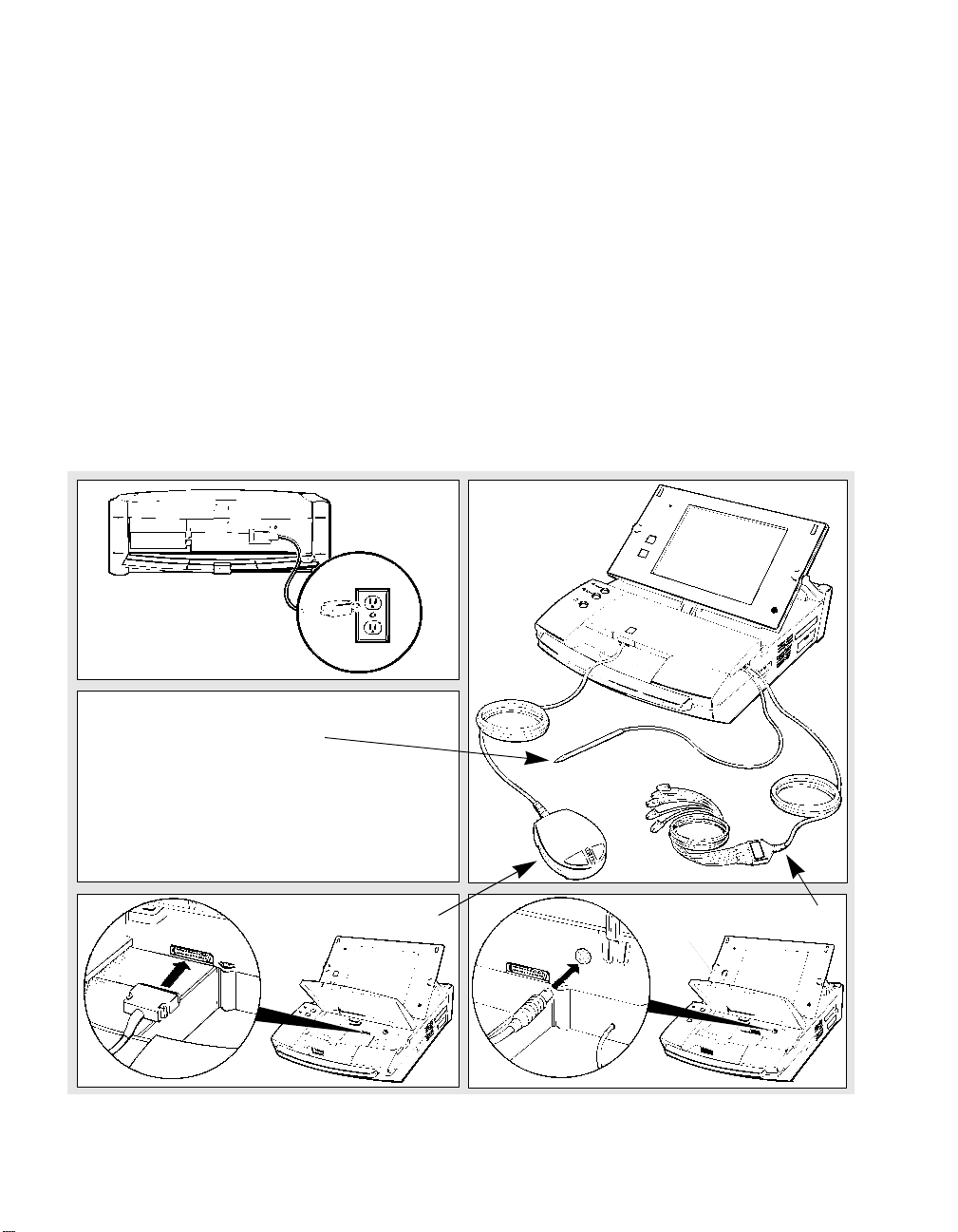
Programmer Setup Check List
Verify that the components illustrated below are properly
connected to the programmer.
Power Cord
1.
Selector Pen (Stylus)
2.
Do not disconnect
NOTE:
the stylus.
Programming Head
3.
Figure 1-1. Setting Up the Programmer
1-2 Medtronic.Kappa® 400 Series Pacemaker Programming Guide
Compartment
Latch
ECG Cable
4.
13

Connecting an External Monitor/Recorder
To connect an external monitor or recorder to your programmer
you need the optional adaptor shown below. Connect the adaptor
to the analog output port on the right side of the programmer.
Signal Output Adaptor
Programmer Basics
Setting Up the 9790 Programmer
D
±1V
A
BC
±5mV
Connect the optional adaptor to the
Analog Output port on the programmer.
Adaptor Output Signals (after model selection):
A
- Patient’s ECG (upper most ECG on display)
B
- Telemetered EGM (uppermost EGM on display)
C
- Telemetered EGM (other EGM if programmed)
D
- Marker Channel™ Telemetry
Connector Type:
Output Signal:
BNC
±
1 Volt or ±5 mV (switchable)
Figure 1-2. Connecting the Optional External Adaptor
Using the Calibrate Button
Calibrate Button
Marker Channel and EGM Calibration
Signals
Atrial Pace (AP)
Atrial Sense (AS)
Atrial Refractory Sense (AR)
Vent. Refractory Sense (VR)
Vent. Sense (VS)
Vent. Pace (VP)
5 mV
1 mV
14
Selecting the Calibrate button located next to the analog output
port adds a reference signal (as shown in Figure 1-2) to the trace of
Marker Channel™ and EGM telemetry.
The Marker Channel signal shows the relative marker amplitudes,
which are not annotated with character codes on an external
device. The EGM calibration signal acts as a voltage reference for
the displayed EGM.
Medtronic.Kappa® 400 Series Pacemaker Programming Guide 1-3
Programmer Basics
Connecting the Programmer to Skin Electrodes
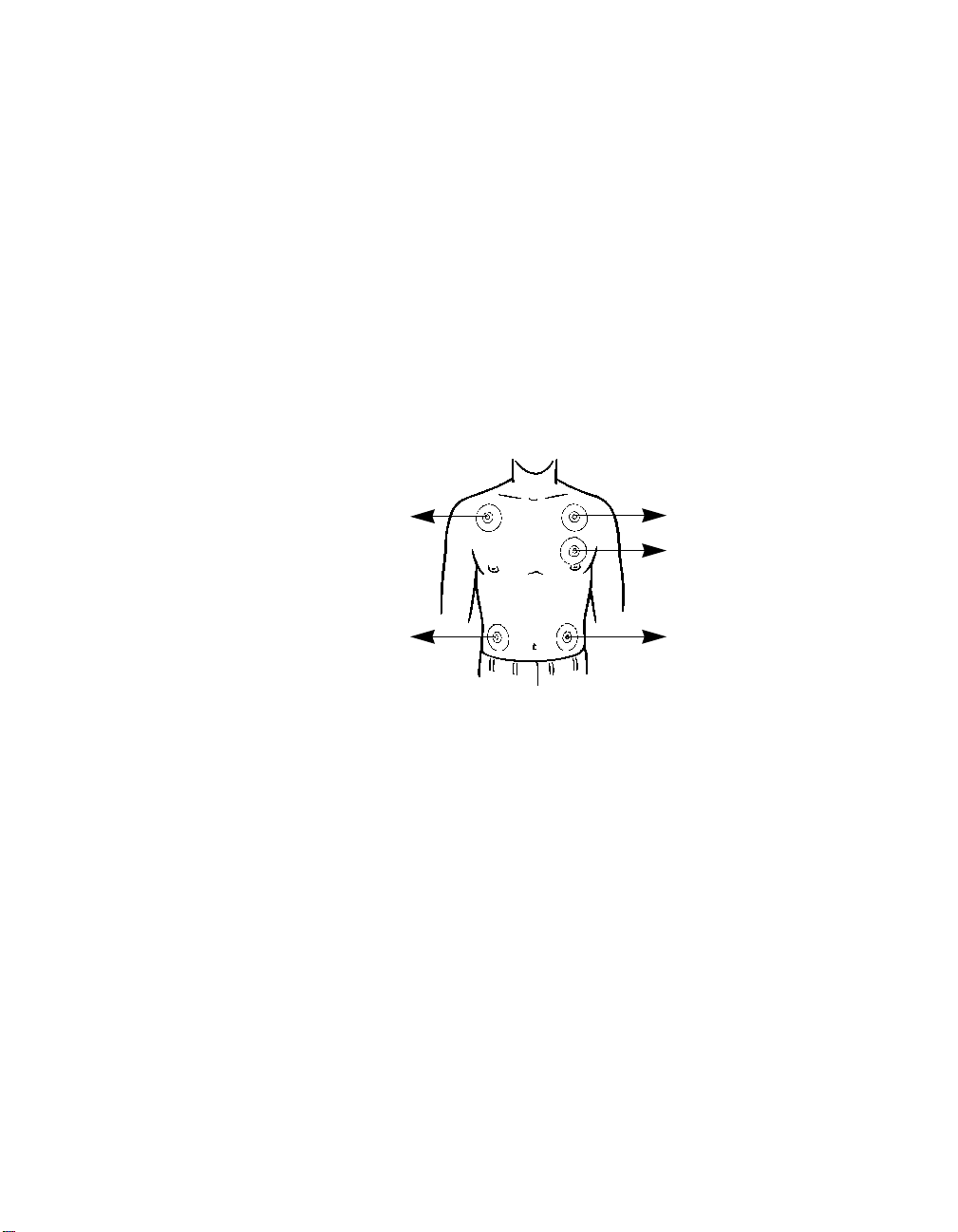
Connecting the Programmer to Skin Electrodes
At the start of a patient session, the programmer must be
connected to skin electrodes on the patient. The ECG display and
measurement functions will not operate without detection of the
surface ECG signal.
Use an electrode lead to connect each skin electrode to the
appropriate port on the ECG cable. Typical electrode placement is
shown below. Use standard procedures for attaching disposable
skin electrodes to the patient.
RA (R)
RL (N)
Figure 1-3. Connecting the Programmer to Skin Electrodes
Refer to the guide, Programmer Description and Setup, supplied
with your 9790 programmer for more details on this procedure.
LA (L)
C (C)
LL (F)
( ) = IEC Coding
1-4 Medtronic.Kappa® 400 Series Pacemaker Programming Guide
15

Programmer Basics
Positioning and Using the Programming Head
Positioning and Using the Programming Head
In many of the procedures described in the following chapters,
you will be directed to position the programming head over the
patient’s pacemaker.
When to Position the Programming Head
You must position the programming head over the patient’s
pacemaker whenever a procedure initiates communication
between the programmer and pacemaker. Examples are:
Positioning the
Programming Head
Light
Array
Green
Amber/Green
■ At the start of a patient session when you select the
Identify
or
button. The programmer automatically initiates
Start
Auto-
an interrogation that takes a number of seconds to complete.
■ Prior to executing any command that results in a telemetry or
programming transmission.
■ To view or record Marker Channel™ or EGM telemetry.
CAUTION: Do not position the programming head over an
implanted pacemaker during electrocautery or defibrillation
procedures.
How to Position the Programming Head
The programming head must be properly positioned as described
below. An incorrectly positioned programming head can result in
the failure of a transmitted command and the loss of telemetry.
1. Hold the programming head directly against the patient’s
skin with the face of the programming head parallel to the
pacemaker.
2. Position the programming head so that the amber light in
the light array goes out and one or more of the green lights
come on. Move the head a little in each direction to find the
position that lights the greatest number of green lights. This
is the optimum position.
16
Medtronic.Kappa® 400 Series Pacemaker Programming Guide 1-5
Programmer Basics
Positioning and Using the Programming Head
Effect of the Programming Head on
Pacemaker Operation
If model selection and application (software) loading are
complete, positioning the programming head over a
Medtronic.Kappa® Series 400 pacemaker does not put the
pacemaker in the magnet mode of operation, as is the case with
previous pacemaker models. The programmer automatically
sends a Cancel Magnet command to the pacemaker, which causes
it to continue to operate as programmed.
An exception to this operation can occur if the programming head
does not establish a telemetry link with the pacemaker (because of
strong electrical interference or because the programming head is
improperly positioned). In such cases, positioning the
programming head would result in magnet mode operation until
a telemetry link is established. You can easily verify the present
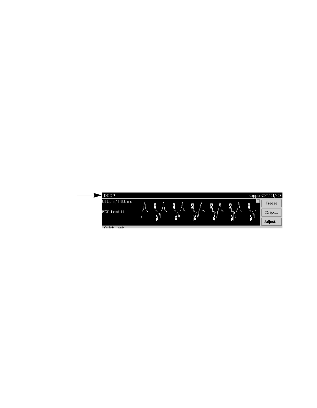
The present pacing mode
shows in the status bar at
the top of the screen.
pacing mode by observing the Status Line at the top of the screen.
Pacemaker operation returns to its permanently programmed
state about 2 seconds after you remove the programming head
from its position over the pacemaker.
Observing Magnet Mode Operation
To observe magnet mode operation during a patient session, you
must conduct the Magnet test described in Chapter 2. Initiating
the Magnet test results in a Threshold Margin Test (TMT) and
causes the pacemaker to operate in the magnet mode.
NOTE: Between patient sessions before you select the pacemaker
model, positioning the programming head over a
Medtronic.Kappa® Series 400 pacemaker will result in magnet
mode operation.
1-6 Medtronic.Kappa® 400 Series Pacemaker Programming Guide
17

Programmer Basics
Positioning and Using the Programming Head
Alternative
PROGRAM
and
INTERROGATE
Buttons
To initiate the Program and Interrogate commands, you have the
option to use the on-screen
Program (
Interrogate
The P or I button on the programming head is active only when its
counterpart is displayed as an active button on the display screen.
) and Interrogate (I) buttons on the programming head.
P
Light Array
Button
Figure 1-4.
Alternative
Program
Program
and
Interrogate
Programming Head
and
Interrogate
buttons or the
Program
Buttons
Button
Automatic Interrogation at the Start of a
Session
18
At the start of a session when you select
programmer automatically interrogates the patient’s pacemaker
for all the data contained within the pacemaker. For this process,
you must position the programming head and hold it steady in
place until the interrogation is complete.
At the bottom center of the screen you will see an indicator
showing the progress of the interrogation. Because this
interrogation retrieves all the data stored in the pacemaker,
including diagnostic data, the process may take a number of
seconds.
Medtronic.Kappa® 400 Series Pacemaker Programming Guide 1-7
Start
or
Auto Identify
, the

Programmer Basics
About the Display Screen
About the Display Screen
The programmer display screen is an interactive device that not
only displays information in the form of both text and graphics,
but functions as a control panel by displaying buttons and menu
options that you can select using the stylus.
Features and Conventions of the
Display Screen
This section describes the features and conventions of the display
screen. The Therapy Parameters screen below shows the main
elements of the typical screen.
Status Bar
Live Rhythm
Monitor Window
Task Area
Command Bar
Active Fields Buttons Tool Palette
Figure 1-5. Main Elements of a Display Screen Example
1-8 Medtronic.Kappa® 400 Series Pacemaker Programming Guide
19

Status Bar
Programmer Basics
About the Display Screen
The Status Bar
The status bar at the top of the screen shows:
■ The present pacing mode.
■ When any one of a number of test conditions is occurring.
■ The pacemaker model.
The Live Rhythm Monitor Window
This window is a partial view of the full-screen display of ECG,
Marker Channel™, and telemetered EGM waveform traces. You
can expand this window to its full size by selecting the small
square button in the upper-right corner of the window or by
selecting the
Adjust...
button.
Heart rate and rate
interval show if the
programming head is
positioned over the
pacemaker.
Annotations above the
waveform trace show the
point of programmed
parameter changes.
20
The waveform trace or traces that show in this window depend on
the selected task screen and how traces have been arranged in the
full-screen view. Refer to Chapter 4 for information about the live
rhythm monitor.
The Task Area
The portion of screen between the live rhythm monitor window at
the top and the command bar at the bottom changes according to
the task or function you select. The example in Figure 1-5 shows
the Therapy Parameters screen for programming pacemaker
parameter settings. This task area would appear much different if
you selected, for example, the Threshold Test Setup screen.
Medtronic.Kappa® 400 Series Pacemaker Programming Guide 1-9

Programmer Basics
About the Display Screen
Active fields show
as unshaded areas
on the screen.
The Command Bar
The bar at the bottom of the screen always shows the command
buttons for programming “emergency” parameters settings,
interrogating the pacemaker, and ending the patient session.
Programming emergency parameters is covered later in this
chapter; interrogating the pacemaker and ending the session are
discussed in Chapter 2.
Active Fields
Unshaded areas, or boxes, appearing in the task area are “active
fields” that respond to the stylus.
Selecting a value, word, name, or phrase that appears in an active
field opens a menu or window of alternative options for whatever
is represented in that field.
For example, touching the amplitude value “3.50 V” in the Atrial
Lead field with the tip of the stylus opens a window of amplitude
value options. Selecting any one of these options replaces the
original 3.50V value with the selected one.
Selecting an active
field opens a menu or
window of alternative
options, or in some
cases, an on-screen
keyboard.
1-10 Medtronic.Kappa® 400 Series Pacemaker Programming Guide
21

Buttons having a less
distinct shaded label
are not presently
active.
Programmer Basics
About the Display Screen
Selecting some fields (those with terms ending in an ellipsis, such
as “Rate Response...”) open a window displaying additional
fields. Some fields that require entry of information, such as
patient data, open an on-screen keyboard. How to use this
keyboard is described later in this section.
Buttons
Buttons like those shown below let you operate the programmer
using the stylus. You can “press” a button by touching it with the
tip of the stylus.
Buttons
Icons
Buttons may directly execute a command, such as the
Program
button, or they may open a window that prompts another action.
Usually such buttons have a label ending with an ellipsis, such as
the
Save...
or
buttons shown above.
Get...
A procedure may instruct you to “press and hold” a button. In
such cases you should touch the tip of the stylus to the button and
continue to maintain pressure against the button until it is time to
“release” the button.
The Tool Palette
The collection of buttons and icons along the edge of the screen is
referred to as the “tool palette.” These are the controls you will use
to choose the task or function screen you want displayed. Once
you have started a patient session, the tool palette is always
displayed, making it quick and easy to move to the desired task or
function.
Each of the icons acts like a button. To select an icon, touch the icon
with the stylus. The “<“ symbol adjacent to three of the icons
indicates that selecting one of these icons opens a menu of related
options. The icons without the < symbol directly open a task
screen.
22
Medtronic.Kappa® 400 Series Pacemaker Programming Guide 1-11

Programmer Basics
About the Display Screen
Refer to Table 2-1 in Chapter 2 for a brief explanation of the
purpose of each button and icon in the tool palette.
Using the On-Screen Keyboard
Certain fields on the screen allow you to enter data, such as the
patient’s name or file number. Selecting such a field automatically
displays the on-screen keyboard shown below. By touching the
letter or character buttons with the stylus, you can use this display
feature like an actual keyboard.
Text Entry Window
Space Bar
Figure 1-6. Keyboard Screen
The function of the on-screen keyboard buttons are very similar to
the keys on a typewriter or computer keyboard.
1-12 Medtronic.Kappa® 400 Series Pacemaker Programming Guide
23
Cursor Position Keys

Table 1-1. Keyboard Buttons
Button or Feature Function
Programmer Basics
About the Display Screen
Text Entry Window
(See Figure 1-6)
Shows the text as you enter it using the keyboard.
You can enter only as many characters as can fit
in the selected field.
Clears all characters from the Text entry window.
Closes the Keyboard screen without changing the
selected field.
Deletes the character to the left of the cursor in
the data entry window.
Has no effect.
Locks all characters into upper case until the
key is selected again. While the
Caps
down, the
Shift
and
Shift Lock
keys operate as
Caps
key is
described below except that characters will shift
to lower case.
Shifts all of the characters into upper case and
replaces the top row of numbers with commonly
used symbols. This shift cancels automatically
after you select a character or symbol.
Locks all of the characters into upper case and
replaces the top row of numbers with commonly
used symbols. Press this key again to return to
number keys and lower case.
24
Shifts the keyboard to a limited set of characters.
Selecting a character or symbol cancels Alt.
Space Bar
Inserts a blank space.
(See Figure 1-6)
Moves the cursor one space to the left or the
right.
Closes the Keyboard screen and enters the text
in the text entry window into the selected field.
Medtronic.Kappa® 400 Series Pacemaker Programming Guide 1-13

Programmer Basics
About the Display Screen
Audible Tones
Certain events in the operation of the programmer result in an
audible signal. The following tones alert the user to the success or
failure of an action.
■ A two-tone beep (low-to-high) indicates confirmation of an
Interrogate or a Program command.
■ A single low-tone beep indicates that an Interrogate, Program,
or Emergency command was not confirmed. It can also
indicate that the selected command cannot be executed.
■ A single, short beep coincides with pressing the Interrogate
or the Program button. It also occurs upon automatic
identification of the pacemaker.
1-14 Medtronic.Kappa® 400 Series Pacemaker Programming Guide
25

Programming Emergency Parameters
Programming Emergency Parameters
The Emergency programming command is a safety feature that
overrides all other functions and immediately programs the
pacemaker to preset emergency values intended to provide
pacing support under a variety of conditions. This programming
cancels any temporary function in effect and restores magnet
mode operation.
To program Emergency parameters:
1. Position the programming head over the pacemaker.
2. Take either of the following actions:
Programmer Basics
■ Press the square red
button on the left side of
the display panel.
■ Or, select the on-screen
+
Emergency
button in the
Emergency Button
(Red)
Deliver Button
(Yellow on Blue)
+ Emergency
lower left corner of the
screen.
3. Hold the programming head steady until a confirmation
message appears. If programming is not confirmed, verify
that the programming head is properly positioned and then
reselect the
Emergency
button or the square red button.
Emergency values are permanent settings that provide higherthan-normal energy output. It is not intended that the pacemaker be
left at these settings. Refer to Section B in Volume II for a list of
Emergency parameters settings for the Kappa® series 400
pacemakers.
26
Medtronic.Kappa® 400 Series Pacemaker Programming Guide 1-15

Programmer Basics
Recording an ECG Strip
Recording an ECG Strip
At any time during a patient session, you can initiate a
continuous, real-time ECG recording as described below.
To start an ECG recording:
➤ Press the desired paper speed button (
25 mm/sec
2.5 mm/sec
Paper Advance
Figure 1-7.
ECG Chart Recorder Control Buttons
25 mm/sec, 12.5 mm/sec
To stop the recording:
➤ Press the same paper speed button again.
Before you tear off the ECG strip, press the
button to advance the strip to a perforation.
Paper Advance
).
1-16 Medtronic.Kappa® 400 Series Pacemaker Programming Guide
27

Annotations
ECG Trace
Programmer Basics
Recording an ECG Strip
About the ECG Recording
Because the printed recording provides a higher resolution, it may
show artifacts and events that do not appear on the display.
Annotation of Executed Commands – Information on the ECG
printout includes an indication of when certain commands to the
pacemaker occurred. When confirmation of the command is
received, the command name is printed at the appropriate point
in the margin above the waveform grid. A recording made during
use of the following test functions will show the programmed test
values as they are programmed: Magnet, Underlying Rhythm,
Threshold, Manual Sensing, and Temporary.
Marker Telemetry
EGM Telemetry
28
Figure 1-8. Example ECG Printout with Marker and EGM Telemetry
Marker Channel™ and EGM Telemetry – If the programming
head is positioned over the patient’s pacemaker, the recording will
include a trace or traces of the telemetry being received from the
pacemaker. In this example, the patient’s ECG is accompanied by
Marker and EGM telemetry.
ECG and EGM Trace Adjustment – The ECG and EGM are
recorded according to control settings accessible from Adjust
window (see Chapter 4). The ECG source (Lead I, II, or III) printed
is the ECG trace appearing first in the live rhythm monitor
window on the programmer screen.
Medtronic.Kappa® 400 Series Pacemaker Programming Guide 1-17

Programmer Basics
Recording an ECG Strip
Missing Markers – A programming command or interrogation
momentarily interrupts the transmission of Marker Channel™
telemetry. This interruption can result in missing markers. The
point at which the command occurred is marked above the ECG
trace by a “down” and/or “up” arrow. The down arrow (▼)
indicates a transmitted command from the programmer; the up
arrow (▲) indicates a telemetry response from the pacemaker.
1-18 Medtronic.Kappa® 400 Series Pacemaker Programming Guide
29

Using the On-line Help Feature
The On-line Help system provides information on-screen about
many of the features and operations of the programmer. When
you request Help, a Help window opens (covering much of the
workspace temporarily). If the initial Help window does not have
the information you were seeking, you can find another one that
does by using the buttons and icons listed in Table 1-2.
When you are ready to leave the On-line Help system, simply
close the Help window. You will return to the workspace that was
in view before you requested Help.
Table 1-2. Getting Around in the Help System
Button or Icon What It Does
Specific Help — If this icon is displayed within a
screen or window, select it to get specific help
related to that screen or window.
This icon is displayed only if Specific Help is
available.
General Help — Select this button at any time to
enter Help, starting with a Topics list.
Previous
Close
button Displays the Help window last viewed or closes
the Help window first opened.
button Closes the Help window.
Programmer Basics
Using the On-line Help Feature
30
button Displays a list of terms discussed in Help. From
Index
button Displays a list of all available Help topics. From
Topics
(underlined phrase
Scroll bar Use this if a Help topic extends beyond the
this list, you can select a Help topic to learn
about one of the terms.
this list you can select any topic.
Link icon — Indicates that more Help is
available. Select this symbol to jump to a related
topic.
Some pictures may have links also.
) Definition available — Select the phrase to see
a pop-up window that defines the phrase. Select
Previous
window size.
to close the pop-up window.
Medtronic.Kappa® 400 Series Pacemaker Programming Guide 1-19
Programmer Basics
Using the On-line Help Feature
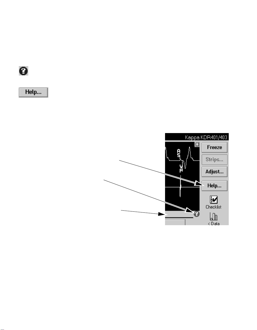
Entering the Help System
Figure 1-9 shows ways to enter the Help system:
■ If the
icon is present, select it for specific help about the
?
screen or window in which it appears. This icon appears near
the window’s title bar when specific help is available.
■ Select the Help… button, which is always present. This leads
you directly to a topics list so that you can search for
information. You can also search by using a Help index.
Once you have entered the Help system, you can use the built-in
links to jump from the current Help window to other related Help
windows.
button for
Help…
general Help
icon for specific
?
Help
Title bar for
window having
specific Help
Figure 1-9. Entering On-line Help
1-20 Medtronic.Kappa® 400 Series Pacemaker Programming Guide
31

Programmer Basics
Using the On-line Help Feature
Using the Links in Help
Figure 1-10 shows the links that allow you to see additional Help
windows:
Topic
window
Pop-up
definition
window
■ The basic link, whose icon is
, indicates that more Help is
available. Select it to jump to a related topic.
■ The definition link, whose symbol is an underlined phrase,
indicates that there is a pop-up window to define the phrase.
Select the phrase to open the pop-up window. Select outside
the pop-up window (or select
Previous
) to close it.
Note: Some pictures may have links also. Each of these
pictures has instructions on how to select the links and where
they lead.
If you have viewed a series of topics and wish to return to a topic
viewed earlier in that series, you can use the
Previous
button to go
backward through the series of topics one at a time.
32
Link to
definition
window
Help push buttons
Figure 1-10. Typical Help Windows (Topic and Definition)
Link to another
Help topic
Medtronic.Kappa® 400 Series Pacemaker Programming Guide 1-21
Scroll bar

Programmer Basics
Using the On-line Help Feature
Exiting the Help System
When you are ready to leave Help and return to the programmer
workspace, select the
the programmer screen displays the same information that it did
when you entered Help.
button. The Help window closes, and
Close
Note: Except for the
Emergency
button, no other functions on the
programmer screen are usable when Help is open. To use other
programmer functions, you must first exit the Help system.
Searching for Information in Help
If you do not find the information you were looking for in the
current Help screen, there are several methods for searching for it:
■ Topics List — Select the
having two columns. The column on the left lists categories of
Help topics. One of these categories is always selected, and
the topics for that category are listed in the right-hand
column. You can view:
– any of the topics listed (on the right) by selecting the link
icon ( ) next to its name, or
– another category by selecting its name (on the left).
Figure 1-11 shows what happens when you select a different
category. In this example, the category “Initial Help” is
selected first. The right-hand column lists topics included in
this category. Suppose that you are searching for Help on one
of the pacing therapies. If you select “Pacemaker Features” as
a new category, notice that the right-hand column changes.
You can then select a link icon ( ) for the specific topic you
would like to view.
push button to open a window
To pi c s
■ Help Index — Select the
lists indexed terms in alphabetical order. Like a book index,
the terms are not limited to titles in Help. You can go to a Help
window explaining any of the indexed terms by selecting the
link icon ( ) next to that term.
Figure 1-12 shows some typical index entries.
1-22 Medtronic.Kappa® 400 Series Pacemaker Programming Guide
33
button to open a window that
Index
 Loading...