

Page 1

KAPPA® 700/600 SERIES
197907002A_view.pdf
PA C E M A K E R S
Model 9953 1.3
Pacemaker Programming Guide
Caution: Federal Law (USA) restricts this device to sale by or on
the order of a physician (or properly licensed practitioner).
Page 2

Page 3

Medtronic Kappa™ 700/600 Series
Pacemaker Programming Guide
A guide to using the 9790 Series
programmer for Medtronic
Kappa 700/600 Series
pacemakers
Refer to the Medtronic Kappa 700/600
Series Pacemaker Reference Guide for
information on the pacemakers.
Page 4

The following are trademarks of Medtronic:
Capture Management, Checklist, FAST, Fast Path, Implant Detection,
Kappa, Key Parameter History, Marker Channel, Medtronic, Medtronic
Kappa, Medtronic Vision, Rate Profile Optimization, Remote Assistant,
Auto-PVARP, Quick Look, Search AV, Sensing Assurance, Significant
Events, Sinus Preference, and Vision.
Page 5

How to Use This Guide
Information is Contained in Two Guides
Product information about Medtronic Kappa 700/600 Series software and
pacemakers is presented in two separate guides.
The Pacemaker Programming Guide (PPG) accompanies Medtronic
Kappa 700/600 Series software and contains instructions on how to use
the programmer and the programming software.
The Pacemaker Reference Guide (PRG) is a supplementary guide that
provides detailed information on Medtronic Kappa 700/600 Series
pacemakers.
About this Guide
This guide presents the following information to use the 9790
programmer.
■
How to setup and configure the programmer and access on-line help.
■
How to start a patient session, use the various follow-up features
during the session, and properly end the session.
■
How to use checklist to streamline a follow-up session.
■
How to view and print the patient’s ECG and EGM waveform traces.
■
How to configure the pacemaker to collect diagnostic data and how
to retrieve and view this information.
■
How to measure stimulation thresholds and sensing levels.
■
How to program parameter values and verify rate response
parameters settings.
How to Use This Guide
Medtronic Kappa™ 700/600 Series Pacemaker Programming Guide v
Page 6

How to Use This Guide
About the Pacemaker Reference Guide
This supplementary guide describes in detail, how the pacemaker
operates and specifies the capabilities of each model.
■
Describes the pacing modes, rate response options, special therapy
features, telemetry types, and data collection options. In some cases,
guidelines are given on how to configure the pacemaker operation.
■
Contains troubleshooting information for electrical and hemodynamic
problems.
■
Specifies parameter and data collection capabilities, longevity
projections, and mechanical and electrical specifications.
■
Provides general warning and cautions, potential interference
sources, and general indications for pacing.
■
Contains a glossary of terms.
vi Medtronic Kappa™ 700/600 Series Pacemaker Programming Guide
Page 7

Table of Contents
1. Programmer Basics
2. Conducting a Patient Session
Table of Contents
How to Use This Guide v
Setting Up the 9790 Programmer 2
Connecting the Programmer to Skin Electrodes 6
Positioning and Using the Programming Head 7
About the Display Screen 12
Programming Emergency Parameters 19
Recording an ECG Strip 20
Using the On-line Help Feature 22
Important Reminders About Medtronic Kappa 700/600 Series
Pacemakers 2
Starting a Patient Session 5
Proceeding with Task Selection 11
Interrogating the Pacemaker 13
Taking a Quick Look at Pacemaker Operation 14
Viewing Battery and Lead Measurements 18
Checking the Present Parameter Settings 22
Viewing Patient Information Stored in the Pacemaker 23
Recording an ECG Strip of Magnet Operation 24
Checking the Patient’s Underlying Rhythm 27
Printing Data Reports 31
Ending a Patient Session 36
3. Streamlining Follow-up with Checklist
About the Checklist Feature 2
Using Checklist to Streamline a Follow-up Session 3
Creating a Custom Checklist 6
4. Viewing the Patient’s ECG and EGM Traces
Viewing the ECG and Other Rhythm Waveforms 2
Adjusting and Configuring the Display 7
Freezing and Analyzing a Waveform Strip 17
Recalling and Viewing Waveform Strips 25
5. Collecting Diagnostic Data
About Data Collected by the Pacemaker 2
Displaying Collected Data 9
Choosing Clinician-Selected Detailed Data Collection 25
Lead Impedance Detail 42
Medtronic Kappa™ 700/600 Series Pacemaker Programming Guide vii
Page 8

Table of Contents
Programming Data Collection 44
Clearing Data From the Pacemaker 47
6. Evaluating Parameter Settings
Measuring Stimulation Thresholds 2
Determining a Sensitivity Setting 23
Using Temporary Programming to Evaluate Parameter Settings 31
7. Programming Pacemaker Parameters
Programming Parameters 2
Saving/Retrieving a Set of Parameter Values 14
8. Rate Response Setup
Using Exercise Test to Verify Rate Response 2
9. Miscellaneous Setup Options - Programmer and Pacemaker
Selecting System Operating Preferences 2
Adjusting Programmer Time and Date 4
Improving the Detection of Pacing Artifacts 5
Checking the Software Version 6
Starting the Demonstrations Option 7
Programming Patient Data into Pacemaker Memory 8
Retrieving Key Parameter History Information 10
Connecting an External Printer 11
A. Appendix: Parameter Values and Restrictions
Programmable Modes and Parameters 2
Automatic and Clinician-Selectable Diagnostics 12
Programming Restrictions 16
I. Index
viii Medtronic Kappa™ 700/600 Series Pacemaker Programming Guide
Page 9

Programmer Basics
This chapter provides an overview of setting up the
programmer and covers information you should be familiar
with before you begin a patient session.
This information includes such things as using the
programming head and stylus, programming Emergency
parameters, and recording an ECG strip. Sections include an
introduction to features of the display screen and use of the
on-line Help system.
For more detailed information on setting up your
programmer, refer to Programmer Description and Setup, a
guide supplied with your 9790 series programmer.
1
Setting Up the 9790
Programmer 1-2
Connecting the Programmer to Skin
Electrodes 1-6
Positioning and Using the
Programming Head 1-7
About the Display Screen 1-12
Programming Emergency
Parameters 1-19
Recording an ECG Strip 1-20
Using the On-line Help Feature 1-22
Medtronic Kappa™ 700/600 Series Pacemaker Programming Guide 1-1
Page 10
Programmer Basics
Setting Up the 9790 Programmer
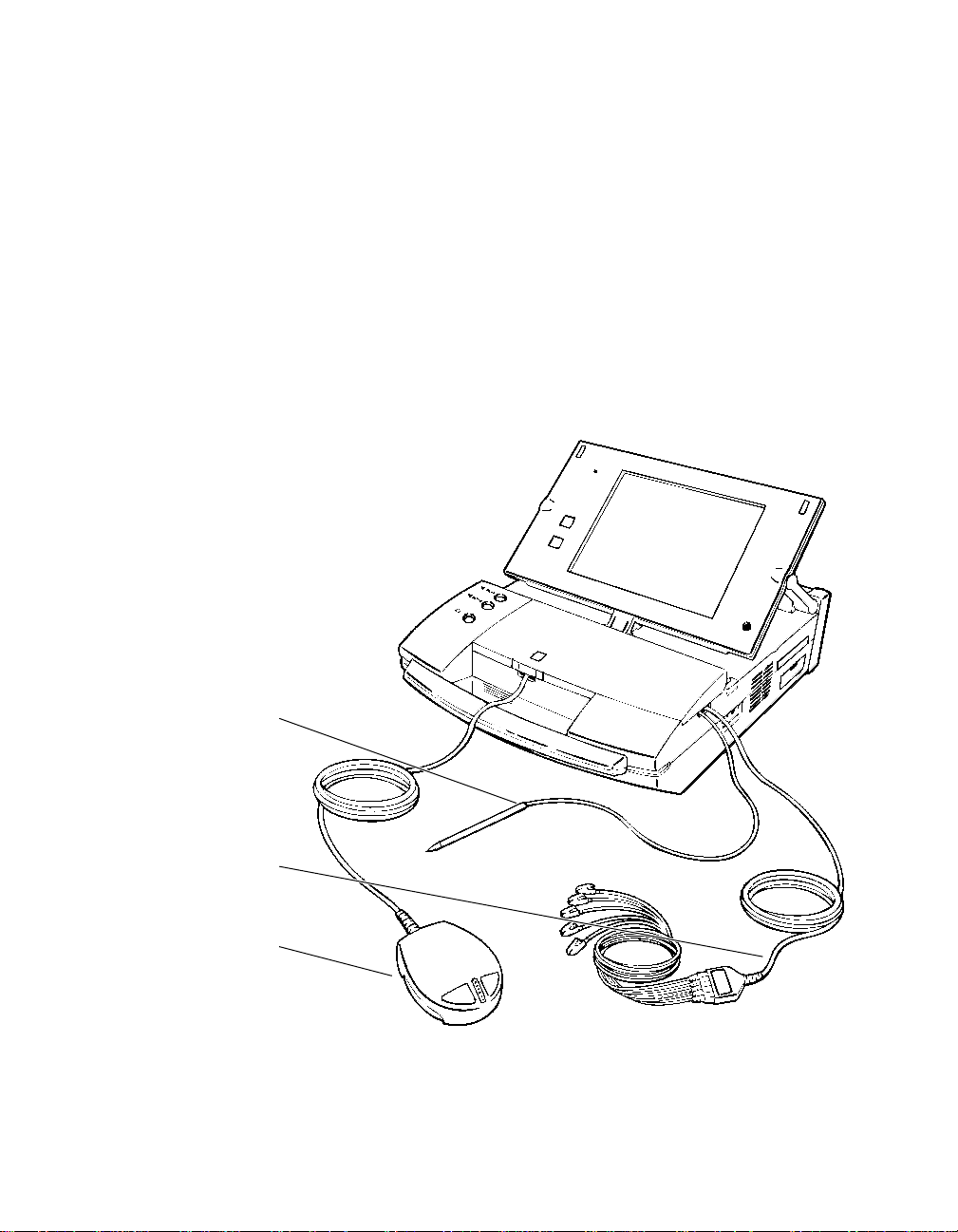
Setting Up the 9790 Programmer
The following topics summarize the basic steps for setting up your 9790
series programmer. For more complete information on setting up your
programmer, refer to the guide, Programmer Description and Setup,
supplied with your programmer.
Programmer Setup Check List
Verify that the components illustrated below are properly connected to the
programmer.
Selector Pen
(Stylus)
Note: Do not disconnect the
Programming Head
1-2 Medtronic Kappa™ 700/600 Series Pacemaker Programming Guide
stylus.
ECG Cable
Figure 1-1. The Programmer
Page 11
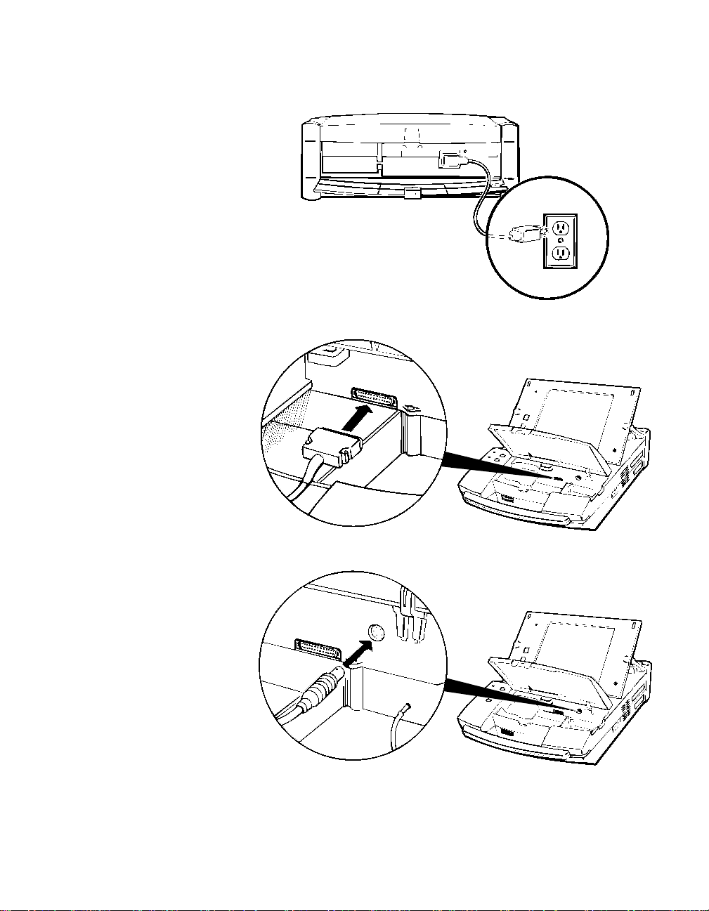
Setting Up the 9790 Programmer
Figure 1-2. Power Cord
Programmer Basics
Figure 1-3. Programming Head
Figure 1-4. ECG Cable
Medtronic Kappa™ 700/600 Series Pacemaker Programming Guide 1-3
Page 12
Programmer Basics
Setting Up the 9790 Programmer
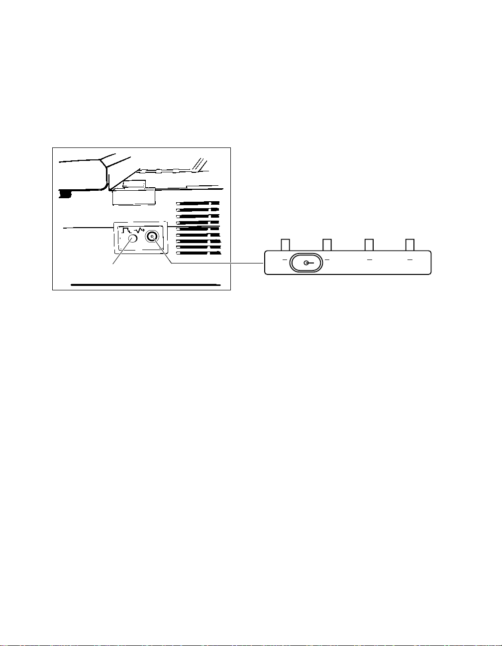
Calibrate Button
Connecting an External Monitor/Recorder
To connect an external monitor or recorder to your programmer, you need
the optional adaptor shown below. Connect the adaptor to the analog
output port on the right side of the programmer.
Connector Type: BNC
Output Signal: ± 1 Volt or ± 5 mV (switchable)
Signal Output Adaptor
A B C D
± 1V ± 5mV
Connecting Optional Adaptor to the Analog Output
Port on the Programmer.
Figure 1-5. Connecting the Optional External Adaptor
Adaptor Output Signals
(after model selection):
A - Patient’s ECG (upper most ECG on display)
B - Telemetered EGM (uppermost EGM on display)
C - Telemetered EGM (other EGM if programmed)
D - Marker Channel Telemetry
1-4 Medtronic Kappa™ 700/600 Series Pacemaker Programming Guide
Page 13

Setting Up the 9790 Programmer
Programmer Basics
Using the Calibrate Button
Selecting the Calibrate button located next to the analog output port adds
a reference signal (as shown in Figure 1-6 and Figure 1-7) to the trace of
Marker Channel and EGM telemetry.
The Marker Channel signal shows the relative marker amplitudes, which
are not annotated with character codes on an external device. The EGM
calibration signal acts as a voltage reference for the displayed EGM.
Atrial Pace (AP)
Atrial Sense (AS)
Atrial Refractory Sense (AR)
Vent. Refractory Sense (VR)
Vent. Sense (VS)
Vent. Pace (VP)
Figure 1-6. Marker Channel Signals
5 mV
1 mV
Figure 1-7. EGM Calibration Signals
Medtronic Kappa™ 700/600 Series Pacemaker Programming Guide 1-5
Page 14

Programmer Basics
Connecting the Programmer to Skin Electrodes
Connecting the Programmer to Skin Electrodes
At the start of a patient session, the programmer must be connected to
skin electrodes on the patient. The ECG display and measurement
functions will not operate without detection of the surface ECG signal.
Use an electrode lead to connect each skin electrode to the appropriate
port on the ECG cable. Typical electrode placement is shown below. Use
standard procedures for attaching disposable skin electrodes to the
patient.
RA (R)
RL (N)
Figure 1-8. Connecting the Programmer to Skin Electrodes
Refer to the guide, Programmer Description and Setup, supplied with your
9790 programmer for more details on this procedure.
LA (L)
C (C)
LL (F)
( ) = IEC Coding
1-6 Medtronic Kappa™ 700/600 Series Pacemaker Programming Guide
Page 15

Positioning and Using the Programming Head
Programmer Basics
Positioning and Using the Programming Head
In many of the procedures described in the following chapters, you will be
directed to position the programming head over the patient’s pacemaker.
When to Position the Programming Head
You must position the programming head over the patient’s pacemaker
whenever a procedure initiates communication between the programmer
and pacemaker. Examples are:
■
At the start of a patient session when you select the [Auto-Identify]
or [Start] button. The programmer automatically initiates an
interrogation that takes a number of seconds to complete.
■
Prior to executing any command that results in a telemetry or
programming transmission.
■
To view or record Marker Channel or EGM telemetry.
Caution: Do not position the programming head over an implanted
pacemaker during electrocautery or defibrillation procedures.
Medtronic Kappa™ 700/600 Series Pacemaker Programming Guide 1-7
Page 16

Programmer Basics
Positioning and Using the Programming Head
How to Position the Programming Head
♦
The programming head must be properly positioned as described below.
An incorrectly positioned programming head can result in the failure of a
transmitted command and the loss of telemetry.
1. Hold the programming head directly against the patient’s skin with
the face of the programming head parallel to the pacemaker.
2. Position the programming head so that the amber light in the light
array goes out and one or more of the green lights come on. Move
the head a little in each direction to find the position that lights the
greatest number of green lights. This is the optimum position.
Figure 1-9. Positioning the Programming Head
Light Array
Figure 1-10. Light Array Indicator
1-8 Medtronic Kappa™ 700/600 Series Pacemaker Programming Guide
Green
Amber/Green
Page 17

The present pacing mode
shows in the status bar at the
top of the screen.
Positioning and Using the Programming Head
Programmer Basics
Effect of the Programming Head on Pacemaker Operation
If model selection and application (software) loading are complete,
positioning the programming head over a Medtronic Kappa 700/600
Series pacemaker does not put the pacemaker in the magnet mode of
operation, as is the case with previous pacemaker models. The
programmer automatically sends a Cancel Magnet command to the
pacemaker, which causes it to continue to operate as programmed.
An exception to this operation can occur if the programming head does
not establish a telemetry link with the pacemaker (because of strong
electrical interference or because the programming head is improperly
positioned). In such cases, positioning the programming head would
result in magnet mode operation until a telemetry link is established. You
can easily verify the present pacing mode by observing the Status Line at
the top of the screen.
Pacemaker operation returns to its programmed state about 2 seconds
after you remove the programming head from its position over the
pacemaker.
Medtronic Kappa™ 700/600 Series Pacemaker Programming Guide 1-9
Page 18

Programmer Basics
Positioning and Using the Programming Head
Observing Magnet Mode Operation
To observe Magnet mode operation during a patient session, you must
conduct the Magnet test described in Chapter 2. Initiating the Magnet test
results in a Threshold Margin Test (TMT) and causes the pacemaker to
operate in the Magnet mode.
Note: Between patient sessions before you select the pacemaker model,
positioning the programming head over a MedtronicKappa 700/600
Series pacemaker will result in magnet mode operation.
Alternative PROGRAM and
INTERROGATE Buttons
To initiate the Program and Interrogate commands, you have the option to
use the on-screen [Program] and [Interrogate] buttons or the Program
[P] and Interrogate [I] buttons on the programming head.
Light Array
[Interrogate] Button
Figure 1-11. Alternative Program and Interrogate
Programming Head Buttons
Note: The [P] or [I] button on the programming head is active only when
its counterpart is displayed as an active button on the display screen.
1-10 Medtronic Kappa™ 700/600 Series Pacemaker Programming Guide
[Program] Button
Page 19

Positioning and Using the Programming Head
Programmer Basics
Automatic Interrogation at the
Start of a Session
At the start of a session when you select [Start] or [Auto Identify], the
programmer automatically interrogates the patient’s pacemaker for most
of the data contained within the pacemaker. For this process, you must
position the programming head and hold it steady in place until the
interrogation is complete.
At the bottom center of the screen you will see an indicator showing the
progress of the interrogation. Because this interrogation retrieves most of
the data stored in the pacemaker, the process may take a number of
seconds.
Medtronic Kappa™ 700/600 Series Pacemaker Programming Guide 1-11
Page 20

Programmer Basics
About the Display Screen
About the Display Screen
The programmer display screen is an interactive device that not only
displays information in the form of both text and graphics, but functions as
a control panel by displaying buttons and menu options that you can
select using the stylus.
Features and Conventions of the
Display Screen
This section describes the features and conventions of the display screen.
The Therapy Parameters screen below shows the main elements of the
typical screen.
Status Bar
Live Rhythm
Monitor Window
Task area
Active Field Button Tool PaletteCommand Bar
Figure 1-12. Main Elements of a Display Screen Example
1-12 Medtronic Kappa™ 700/600 Series Pacemaker Programming Guide
Page 21

Status Bar
Programmer Basics
About the Display Screen
Note: For information on changing the language in the screens (for
example, from English to German), see “Selecting System
Operating Preferences” on page 9-2.
The Status Bar
The status bar at the top of the screen shows:
■
The present pacing mode.
■
When any one of a number of test conditions is occurring.
■
The pacemaker model.
The Live Rhythm Monitor Window
This window is a partial view of the full-screen display of ECG, Marker
Channel, and telemetered EGM waveform traces. You can expand this
window to its full size by selecting the small square button in the upperright corner of the window or by selecting the [Adjust...] button.
■
Heart rate and rate interval show if the programming head is
positioned over the pacemaker.
■
Annotations above the waveform trace show the point of
programmed parameter changes.
Live Rhythm Monitor Window
The waveform trace or traces that show in this window depend on the
selected task screen and how traces have been arranged in the fullscreen view. Refer to “Viewing the ECG and Other Rhythm Waveforms”
on page 4-2 for information about the live rhythm monitor.
Medtronic Kappa™ 700/600 Series Pacemaker Programming Guide 1-13
Page 22

Programmer Basics
About the Display Screen
The Task Area
The portion of screen between the live rhythm monitor window at the top
and the command bar at the bottom changes according to the task or
function you select. The example in Figure 1-12 shows the Therapy
Parameters screen for programming pacemaker parameter settings. This
task area would appear much different if you selected, for example, the
Threshold Test Setup screen.
The Command Bar
The bar at the bottom of the screen always shows the command buttons
for programming “emergency” parameters settings, interrogating the
pacemaker, and ending the patient session.
For complete information on these functions, see “Programming
Emergency Parameters” on page 1-19, “Interrogating the Pacemaker” on
page 2-13, and “Ending a Patient Session” on page 2-36.
Active Fields
Unshaded areas, or boxes, appearing in the task area are “active fields”
that respond to the stylus.
Active fields show as
unshaded areas on
the screen.
Selecting a value, word, name, or phrase that appears in an active field
opens a menu or window of alternative options for whatever is
represented in that field.
1-14 Medtronic Kappa™ 700/600 Series Pacemaker Programming Guide
Page 23

Programmer Basics
About the Display Screen
For example, touching the mode value “DDDR” in the Mode field with the
tip of the stylus opens a window of mode options. Selecting any one of
these options replaces the original DDDR value with the selected one.
Selecting an active field opens
a menu or window of
alternative options, or in some
cases, an
on-screen keyboard.
Buttons having a less
distinct shaded label are
not presently active.
Selecting some fields (those with terms ending in an ellipsis, such as
“Rate Response...”) opens a window displaying additional fields. Some
fields that require entry of information, such as patient data, open an
on-screen keyboard. How to use this keyboard is described later in
this section.
Buttons
Buttons like those shown below let you operate the programmer using the
stylus. You can “press” a button by touching it with the tip of the stylus.
Buttons may directly execute a command, such as the [Program] button,
or they may open a window that prompts another action. Usually such
buttons have a label ending with an ellipsis, such as the [Save...] or
[Get...] buttons shown above.
A procedure may instruct you to “press and hold” a button. In such cases,
you should touch the tip of the stylus to the button and continue to
maintain pressure against the button until it is time to “release” the button.
Medtronic Kappa™ 700/600 Series Pacemaker Programming Guide 1-15
Page 24

Programmer Basics
About the Display Screen
Buttons
Icons
The Tool Palette
The collection of buttons and icons along the edge of the screen is
referred to as the “tool palette.” These are the controls you will use to
choose the task or function screen you want displayed. Once you have
started a patient session, the tool palette is always displayed, making it
quick and easy to move to the desired task or function.
Each of the icons acts like a button. To select an icon, touch the icon with
the stylus. The “<” symbol adjacent to four of the icons indicates that
selecting one of these icons opens a menu of related options. The icons
without the < symbol directly open a task screen.
Refer to Table 2-1 on page 2-6 for a brief explanation of the purpose of
each button and icon in the tool palette.
Note: The Demo icon is available only when the programmer is operating
in the Demo mode.
Using the On-Screen Keyboard
Certain fields on the screen allow you to enter data, such as the patient’s
name or chart number. Selecting such a field automatically displays the
on-screen keyboard shown below. By touching the letter or character
buttons with the stylus, you can use this display feature like an actual
keyboard.
Text Entry Window
Space Bar
Figure 1-13. Keyboard Screen
The function of the on-screen keyboard buttons are very similar to the
keys on a computer keyboard or typewriter.
1-16 Medtronic Kappa™ 700/600 Series Pacemaker Programming Guide
Cursor
Position Keys
Page 25

Table 1 -1. Keyboard Buttons
Button or Feature Function
Text Entry Window
(See Figure 1-13)
Shows the text as you enter it using the keyboard.
You can enter only as many characters as can fit in
the selected field.
Clears all characters from the text entry window.
Closes the Keyboard screen without changing the
selected field.
Deletes the character to the left of the cursor in the
text entry window.
Has no effect.
Programmer Basics
About the Display Screen
Space Bar
(See Figure 1-13)
Locks all characters into upper case until the
key is selected again. While the
[Shift] and [Shift Lock] keys operate as
the
described below except that characters will shift to
lower case.
Shifts all of the characters into upper case and
replaces the top row of numbers with commonly used
symbols. This shift cancels automatically after you
select a character or symbol.
Locks all of the characters into upper case and
replaces the top row of numbers with commonly used
symbols. Press this key again to return to number
keys and lower case.
Shifts the keyboard to a limited set of characters.
Selecting a character or symbol cancels
Inserts a blank space.
Moves the cursor one space to the left or the right.
Closes the Keyboard screen and enters the text in the
text entry window into the selected field.
[Caps] key is down,
[Caps]
[Alt] key.
Medtronic Kappa™ 700/600 Series Pacemaker Programming Guide 1-17
Page 26

Programmer Basics
About the Display Screen
Audible Tones
Certain events in the operation of the programmer result in an audible
signal. The following tones alert the user to the success or failure of
an action.
■
A two-tone beep (low-to-high) indicates confirmation of an
Interrogate or a Program command.
■
A single low-tone beep indicates that an Interrogate, Program, or
Emergency command was not confirmed. It can also indicate that
the selected command cannot be executed.
■
A single, short beep coincides with pressing the Interrogate or the
Program button. It also occurs upon automatic identification of the
pacemaker.
1-18 Medtronic Kappa™ 700/600 Series Pacemaker Programming Guide
Page 27

Programming Emergency Parameters
Programming Emergency Parameters
The Emergency programming command is a safety feature that overrides
all other functions and immediately programs the pacemaker to preset
emergency values intended to provide pacing support under a variety of
conditions. This programming cancels any temporary function in effect
and restores Magnet mode operation.
Note: Use of the Emergency command will clear the Ventricular Chronic
Lead Trend and Capture Management Trend diagnostic data collected by
the pacemaker. If “Collected Data” has been interrogated previously
during the session, this data will be available for viewing and printing until
the session ends. Collection of new trend data starts after you end the
session.
To Program Emergency Parameters
♦
1. Position the programming head over the pacemaker.
2. Take either of the following actions:
■
Press the square red button on the left side of the display panel.
■
Or, select the on-screen [Emergency] button in the lower left
corner of the screen.
Programmer Basics
Emergency values are
programmed settings that provide
higher-than-normal energy output.
It is not intended that the
pacemaker be left at these
settings. Refer to
Medtronic.Kappa 700/600 Series
Pacemaker Reference Guide for a
list of Emergency parameters
settings for Kappa 700/600 Series
pacemakers.
Medtronic Kappa™ 700/600 Series Pacemaker Programming Guide 1-19
Red Button
Emergency Button
+
Emergency
3. Hold the programming head steady until a confirmation message
appears. If programming is not confirmed, verify that the
programming head is properly positioned and then reselect the
[Emergency] button or the square red button.
Page 28
Programmer Basics
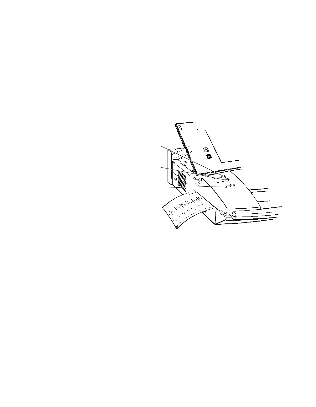
Recording an ECG Strip
Recording an ECG Strip
At any time during a patient session, you can initiate a continuous, realtime ECG recording as described below.
To Start an ECG Recording
♦
➤ Press the desired paper speed button (25 mm/sec or
12.5 mm/sec).
Paper Advance
25 mm/sec
12.5 mm/sec
Figure 1-14. ECG Chart Recorder Control Buttons
To Stop the Recording
♦
➤ Press the same paper speed button again.
Before you tear off the ECG strip, press the [Paper Advance] button
to advance the strip to a perforation.
1-20 Medtronic Kappa™ 700/600 Series Pacemaker Programming Guide
Page 29
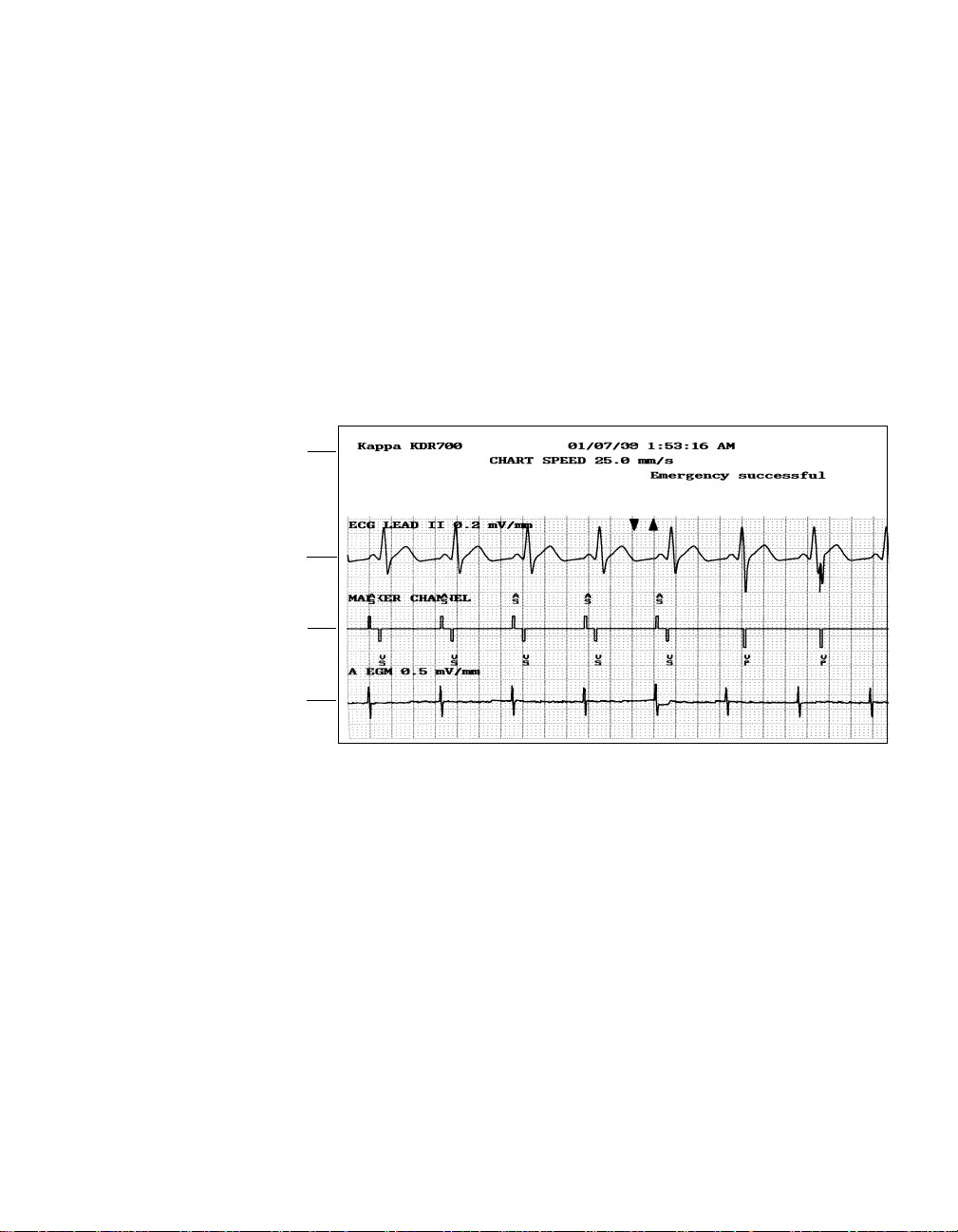
Annotations
ECG Trace
Marker Telemetry
Programmer Basics
Recording an ECG Strip
About the ECG Recording
Because the printed recording provides a higher resolution, it may show
artifacts and events that do not appear on the display.
Annotation of Executed Commands – Information on the ECG printout
includes an indication of when certain commands to the pacemaker
occurred. When confirmation of the command is received, the command
name is printed at the appropriate point in the margin above the waveform
grid. A recording made during use of the following test functions will show
the programmed test values as they are programmed: Magnet,
Underlying Rhythm, Threshold, Sensing, and Temporary.
EGM Telemetry
Figure 1-15. Example ECG Printout with Marker and EGM Telemetry
Marker Channel and EGM Telemetry – If the programming head is
positioned over the patient’s pacemaker, the recording will include a trace
or traces of the telemetry being received from the pacemaker. In this
example, the patient’s ECG is accompanied by Marker and EGM
telemetry.
ECG and EGM Trace Adjustment – The ECG and EGM are recorded
according to control settings accessible from the Adjust window (see
“Adjusting and Configuring the Display” on page 4-7). The ECG source
(Lead I, II, or III) printed is the ECG trace appearing first in the live rhythm
monitor window on the programmer screen.
Medtronic Kappa™ 700/600 Series Pacemaker Programming Guide 1-21
Page 30

Programmer Basics
Using the On-line Help Feature
Missing Markers – A programming command or interrogation
momentarily interrupts the transmission of Marker Channel telemetry.
This interruption can result in missing markers. The point at which the
command occurred is marked above the ECG trace by a “down” and/or
“up” arrow. The down arrow (▼) indicates a transmitted command from the
programmer; the up arrow (▲) indicates a telemetry response from the
pacemaker.
Using the On-line Help Feature
The On-line Help system provides information on-screen about many of
the features and operations of the programmer. When you request Help,
a Help window opens (covering much of the workspace temporarily). If the
initial Help window does not have the information you were seeking, you
can find another one that does by using the buttons and icons listed in
Ta bl e 1 -2 .
When you are ready to leave the On-line Help system, simply close the
Help window. You will return to the workspace that was in view before you
requested Help.
Table 1 -2.
Button or Icon What It Does
Specific Help — If this icon is displayed within a
screen or window, select it to get specific help related
to that screen or window.
This icon is displayed only if Specific Help is available.
General Help — Select this button at any time to enter
Help, starting with a Topics list.
[Previous] button Displays the Help window last viewed or closes the
Help window first opened.
[Close] button Closes the Help window.
[Index] button Displays a list of terms discussed in Help. From this
list, you can select a Help topic to learn about one of
the terms.
[Topics] button Displays a list of all available Help topics. From this list
you can select any topic.
Link icon — Indicates that more Help is available.
Select this symbol to jump to a related topic.
Some pictures may have links also.
Getting Around in the Help System
1-22 Medtronic Kappa™ 700/600 Series Pacemaker Programming Guide
Page 31

Using the On-line Help Feature
Programmer Basics
Table 1 -2. Getting Around in the Help System
Button or Icon What It Does
(underlined phrase) Definition available — Select the phrase to see a
pop-up window that defines the phrase. Select
[Previous] to close the pop-up window.
Scroll bar Use this if a Help topic extends beyond the
window size.
Entering the Help System
Figure 1-16 shows ways to enter the Help system:
■
If the [?] icon is present, select it for specific help about the screen or
window in which it appears. This icon appears near the window’s title
bar when specific help is available.
■
Select the [Help…] button, which is always present. This leads you
directly to a topics list so that you can search for information. You can
also search by using a Help index.
Once you have entered the Help system, you can use the built-in links to
jump from the current Help window to other related Help windows.
[Help…] button for
general Help
[?] icon for
specific Help
Title bar for window having
specific Help
Figure 1-16. Entering On-line Help
Medtronic Kappa™ 700/600 Series Pacemaker Programming Guide 1-23
Page 32

Programmer Basics
Using the On-line Help Feature
Pop-up definition window Link to definition window Scroll Bar
Using the Links in Help
Figure 1-17 shows the links that allow you to see additional Help windows:
■
The basic link, whose icon indicates that more Help is available.
Select it to jump to a related topic.
■
The definition link, whose symbol is an underlined phrase, indicates
that there is a pop-up window to define the phrase. Select the phrase
to open the pop-up window. Select outside the pop-up window (or
select [Previous]) to close it.
Note: Some pictures may have links also. Each of these pictures has
instructions on how to select the links and where they lead.
If you have viewed a series of topics and wish to return to a topic viewed
earlier in that series, you can use the [Previous] button to go backward
through the series of topics one at a time.
Topic window
Help push buttons Link to another
Help topic
Figure 1-17. Typical Help Windows (Topic and Definition)
1-24 Medtronic Kappa™ 700/600 Series Pacemaker Programming Guide
Page 33

Using the On-line Help Feature
Programmer Basics
Exiting the Help System
When you are ready to leave Help and return to the programmer
workspace, select the [Close] button. The Help window closes, and the
programmer screen displays the same information that it did when you
entered Help.
Note: Except for the [Emergency] button, no other functions on the
programmer screen are usable when Help is open. To use other
programmer functions, you must first exit the Help system.
Searching for Information in Help
If you do not find the information you were looking for in the current Help
screen, there are several methods for searching for it:
■
Topics List — Select the [Topics] push button to open a window
having two columns. The column on the left lists categories of Help
topics. One of these categories is always selected, and the topics for
that category are listed in the right-hand column. You can view:
– any of the topics listed (on the right) by selecting the link icon
next to its name, or
– another category by selecting its name (on the left).
Figure 1-18 shows what happens when you select a different
category. In this example, the category “Initial Help” is selected first.
The right-hand column lists topics included in this category. Suppose
that you are searching for Help on one of the pacing therapies. If you
select “Pacemaker Features” as a new category, notice that the righthand column changes. You can then select a link icon for the specific
topic you would like to view.
■
Help Index — Select the [Index] button to open a window that lists
indexed terms in alphabetical order. Like a book index, the terms are
not limited to titles in Help. You can go to a Help window explaining
any of the indexed terms by selecting the link icon next to that term.
Figure 1-19 shows some typical index entries.
Medtronic Kappa™ 700/600 Series Pacemaker Programming Guide 1-25
Page 34

Programmer Basics
Using the On-line Help Feature
Unexpanded Help
categories
To open a
Help topic,
select its
link icon
To expand a new Help category,
select its name
Figure 1-18. Topics List for Help
Expansion of a Help category
select the link icon for its Index
To open a Help topic,
listing.
Figure 1-19. Help Index
1-26 Medtronic Kappa™ 700/600 Series Pacemaker Programming Guide
Page 35

Conducting a
Patient Session
2
This chapter describes how to begin a patient session and how to execute some of the typical tasks you
might use to evaluate operation of the patient’s pacing system.
Included is information about printing, saving, and transferring the data accumulated during the session.
This chapter concludes with a description of how to properly end a patient session.
Important Reminders About
Medtronic Kappa 700/600 Series
Pacemakers 2-2
Starting a Patient Session 2-5
Proceeding with Task
Selection 2-11
Interrogating the Pacemaker 2-13
Taking a Quick Look at Pacemaker
Operation 2-14
Viewing Battery and Lead
Measurements 2-18
Checking the Present Parameter
Settings 2-22
Viewing Patient Information Stored in
the Pacemaker 2-23
Recording an ECG Strip of Magnet
Operation 2-24
Checking the Patient’s Underlying
Rhythm 2-27
Printing Data Reports 2-31
Ending a Patient Session 2-36
Medtronic Kappa™ 700/600 Series Pacemaker Programming Guide 2-1
Page 36

Conducting a Patient Session
Important Reminders About Medtronic Kappa 700/600 Series Pacemakers
Important Reminders About
Medtronic Kappa 700/600 Series Pacemakers
This section lists some of the important features of the Medtronic
Kappa 700/600 Series pacing system.
■
New features of the programmer software
■
Automated rate response
■
Automated monitoring and collection of patient and pacing system
diagnostic data
■
Features that detect implant and automatically update certain
parameter values
New Programmer Features
Auto Cancel Magnet – Cancels the magnet automatically when you
place the programmer head over the pacemaker. With Magnet Test, you
can view and record magnet operation.
Full Auto-Interrogation – Occurs automatically at the start of a session.
Checklist Feature – You can advance quickly to the next task to be done
in a patient session. Clinicians can create custom checklists that
streamline task selection in follow-up and implant sessions.
Full-size Reports – You can choose to connect an external printer for
printing full-size reports.
Live Rhythm Waveform Display – You can quickly tailor a multiple-trace
display of the patient’s ECG, atrial and ventricular EGMs, and Marker
Channel signals.
Saved Session Data – You can save data from a session on a diskette,
which allows you to import session data into a data base.
2-2 Medtronic Kappa™ 700/600 Series Pacemaker Programming Guide
Page 37

Important Reminders About Medtronic Kappa 700/600 Series Pacemakers
Conducting a Patient Session
Automated Rate Response
Rate Profile Optimization – Adjusts rate response levels daily to a
prescribed target profile.
Activity Sensor – Converts detected patient motion into electrical
signals.
New Parameters – ADL Response sets the target profile for moderate
rates; Exertion Response sets the target profile for high rates.
Automated Monitoring and Collection of Patient Diagnostic Data
Diagnostic monitors collect data automatically in the background:
■
Rate, AV Conduction, and Search AV Histograms
■
Sensor Indicated Rate Profile
■
Atrial and Ventricular High Rate Episodes
■
Mode Switch, Rate Drop Response, and Sinus Preference Episodes
■
Lead Monitor Counters
■
Chronic Lead Impedance Trend
■
Capture Management Trend
■
Sensitivity Trend
Remote Assistant
This feature allows the patient to activate data collection when symptoms
are present. The collected data can be used for analysis of the patient’s
rate recorded during symptoms.
Sinus Preference
Promotes tracking of intrinsic atrial activity to increase cardiac output and
extend system longevity.
Medtronic Kappa™ 700/600 Series Pacemaker Programming Guide 2-3
Page 38

Conducting a Patient Session
Important Reminders About Medtronic Kappa 700/600 Series Pacemakers
Automatic Implant Detection
The automatic implant detection feature:
■
Determines that the pacemaker has been implanted and that its
leads are stable and sets lead polarities.
■
Initializes a group of features at implant. These include Sensing
Assurance, Capture Management, rate response, and diagnostic
data collection.
Capture Management
The Capture Management feature checks the patient’s ventricular pacing
thresholds at regular intervals. Using these threshold measurements, the
IPG can determine whether ventricular pacing pulse are capturing the
heart. Optionally, it makes adjustments to the ventricular amplitude and
pulse width parameters based on these measurements.
Sensing Assurance
The Sensing Assurance feature, when active for a specific chamber,
allows the IPG to change the sensitivity threshold for that chamber to track
changes in the sensed amplitude.
Lead Monitor
This feature monitors lead integrity by measuring and recording lead
impedance. Optionally, it can switch either lead (or both leads) from
bipolar to unipolar polarity if lead impedance is out of range.
2-4 Medtronic Kappa™ 700/600 Series Pacemaker Programming Guide
Page 39

Starting a Patient Session
Because the programmer collects and stores data on a session-bysession basis, it is important to correctly start and end each session. This
section describes how to start a patient session. To end a session, refer
to “Ending a Patient Session” on page 2-36.
The Starting Point of a Patient Session
A patient session always begins at the Select Model screen. See
“Procedure for Starting a Patient Session” on page 2-8. If you are
between patient sessions, you can access other screens by using the
icons and buttons described in Table 2-1.
The Select Model screen appears:
■
Upon completion of the self test when you turn the programmer on.
■
After you end a patient session.
Conducting a Patient Session
Starting a Patient Session
Figure 2-1. Select Model Screen
Medtronic Kappa™ 700/600 Series Pacemaker Programming Guide 2-5
Page 40

Conducting a Patient Session
Starting a Patient Session
Notes:
■
If the Select Model screen does not look like this example and you
see a [Medtronic] button, select the button to display this screen.
■
The [Nominals] button does not apply to Kappa pacemakers. This
button allows you to set up Site Nominals if you select a pacemaker
with this feature.
The Tool Palette Between Sessions
Tabl e 2 -1. Tool Palette Between Patient Sessions
Tool Palette Tool Selecting the Tool (Button or Icon)… Reference
Freezes a segment of the live rhythm display.
Note: A frozen strip can be viewed and printed (but not saved)
between patient sessions. Markers and EGM traces are not present
between patient sessions.
Accesses the rhythm strips saved during a patient session.
Note: No saved strips are available between patient sessions.
Opens a window of options for adjusting the live rhythm display.
Note: Additional adjustment options are present during a patient
session.
Displays the screen for selecting a pacemaker model and starting a
patient session.
page 4-17
page 4-25
page 4-7
page 2-5
Displays a queue of print requests from previous sessions as well as
frozen waveform reports requested between sessions.
Displays the programmer setup options.
Preferences
Time and Date
Artifact Detection
Software
Demonstrations
page 2-34
page 9-2
page 9-4
page 9-5
page 9-6
page 9-7
Note: When some functions are active on the display, selecting a tool button or icon will have no effect.
Closing the active window restores operation of the tool palette.
2-6 Medtronic Kappa™ 700/600 Series Pacemaker Programming Guide
Page 41

Conducting a Patient Session
Starting a Patient Session
About Automatic Interrogation
At the start of a patient session when you select the [Auto-Identify]
button or the [Start] button (see “Procedure for Starting a Patient
Session” on page 2-8), the programmer automatically attempts to
interrogate the patient’s pacemaker to retrieve all the data that might be
needed during the session.
Note: To take advantage of this automatic interrogation, you must position
the programming head over the pacemaker and continue to hold it in place
until the interrogation is complete.
The interrogation time may extend to 55 seconds because of the amount
of information stored in the pacemaker. A status gauge at the bottom of
the screen shows progress of the interrogation. The [Stop] button lets you
cancel the interrogation once it has started.
Note: Except for use of the [Emergency] button or the [Stop] button, you
cannot proceed with session activities until the interrogation is 100%
complete.
You can choose to stop interrogation and continue with other activities
(not using the automatic interrogation feature). To do this, select the
[Stop] button or lift the programming head before the process is
complete. In this case, when data is needed, the programmer will display
a message prompting you to interrogate the pacemaker.
You also can manually interrogate the pacemaker at any time during the
patient session (see “Interrogating the Pacemaker” on page 2-13).
Medtronic Kappa™ 700/600 Series Pacemaker Programming Guide 2-7
Page 42

Conducting a Patient Session
Starting a Patient Session
Warning Messages – As a result of an interrogation, a warning message
box may be displayed. Examples of these include:
■
ERI (Elective Replacement Indicator)
■
POR (Power On Reset) or Full Electrical Reset
■
Interrogation interrupted or unsuccessful
■
Lead warnings
■
High threshold measurements
You must acknowledge the message before proceeding with other
activities. For an ERI, POR, lead, or threshold message, you can attempt
to clear them by following the instructions in the message. Otherwise, you
can close the message box and clear the condition later. See “Resetting
ERI or Electrical Reset” on page 7-12.
Procedure for Starting a Patient Session
From the Select Model screen, you can start a patient session by either of
two methods:
■
By selecting the [Auto-Identify] button, which automatically
identifies and selects the patient’s pacemaker model.
■
By selecting the appropriate pacemaker model and then the [Start]
button yourself.
2-8 Medtronic Kappa™ 700/600 Series Pacemaker Programming Guide
Page 43

Conducting a Patient Session
Starting a Patient Session
To Start a Session Using Auto-Identify
♦
1. Display the Select Model screen:
– If the programmer is not operating, turn it on. The power switch
is on the left side and near the back. The Select Model screen
appears after a short, self-test sequence. (Select the
[Medtronic] button if it appears on the screen.)
– If the programmer is operating, but the Select Model screen is
not displayed, choose the Select Model icon from the tool palette
at the side of the screen.
– If the Select Model icon is not in the tool palette, the steps to
properly end the previous patient session have not been
executed. Refer to “Ending a Patient Session” on page 2-36.
2. Position the programming head over the patient’s pacemaker and
continue to hold it steady.
3. Select the [Auto-Identify] button at the bottom of the screen.
After 40 to 50 seconds of internal software loading, the programmer
displays the first task screen. Continue to hold the programming head
in place until the initial interrogation process is 100% complete.
Refer to “Proceeding with Task Selection” on page 2-11 for information on
selecting the functions or tasks you have planned for the session.
Medtronic Kappa™ 700/600 Series Pacemaker Programming Guide 2-9
Page 44

Conducting a Patient Session
Starting a Patient Session
♦
Categories
Models
[Start] button
To Start a Session by Selecting the Pacemaker Model
1. Display the Select Model screen. (Refer to the previous procedure.)
2. Select the appropriate category to view pacemaker models.
3. Select the desired pacemaker model from the list of models.
4. If you want the programmer to automatically interrogate the patient’s
pacemaker, position the programming head.
5. Select the [Start] button.
6. After 40 to 50 seconds of internal software loading, the programmer
displays the first task screen. Continue to hold the programming
head in place until the initial interrogation process is 100%
complete.
Refer to the next topic for information on selecting the functions or tasks
you have planned for the session.
2-10 Medtronic Kappa™ 700/600 Series Pacemaker Programming Guide
Page 45

Proceeding with Task Selection
After you select the [Auto-Identify] or [Start] button to begin a patient
session, a short period of internal software loading occurs before the first
task screen appears.
The First Task Screen
The first task screen to appear is the Quick Look screen. Refer to “Taking
a Quick Look at Pacemaker Operation” on page 2-14 for information
about the Quick Look screen.
Selecting Another Task or Function
To proceed with the session, select the desired task or function from the
button and icon options grouped along the edge of the screen (see
Table 2-2 on page 2-12). This group of buttons and icons is referred to as
the “tool palette.” It is always available (except during the execution of
certain functions) so that you can quickly and easily display a desired task
or function screen.
Conducting a Patient Session
Proceeding with Task Selection
Note: When some functions are active on the display, selecting a tool
button or icon will have no effect. Closing the active window restores
operation of the tool palette.
Consider Using Checklist
Select the Checklist icon to display the Checklist task screen.
During a follow-up session, you can use the tool palette to select tasks or
functions in any order as you proceed through the session. However, if
you use a particular follow-up routine or protocol, you can configure and
use the Checklist feature to streamline your session tasks. Refer to
“Streamlining Follow-up with Checklist” on page 3-1 for information about
using Checklist.
Medtronic Kappa™ 700/600 Series Pacemaker Programming Guide 2-11
Page 46

Conducting a Patient Session
Proceeding with Task Selection
Tab le 2 -2. Tool Palette During a Patient Session
Tool Palette Tool Selecting the Tool (Button or Icon)… Reference
Freezes a segment of the live rhythm display. page 4-17
Accesses the rhythm strips saved since the start of the session. page 4-25
Opens a window of options for adjusting the live rhythm display. page 4-7
Accesses the available Help topics Chapter 1
Displays the screen for setting up and using the Checklist function. page 3-3
Displays the options for retrieving information about the patient’s
pacemaker and its operation and for setting up or clearing the data
collection functions.
Quick Look - Initial Interrogation
Graphs and Tables
Battery and Lead Measurements
Data Collection Setup/Clear
Displays the parameter programming screen. page 7-2
page 2-14
page 5-9
page 2-18
page 5-44
Displays the pacing system test options.
Magnet
Underlying Rhythm
Threshold
Exercise
Sensing
Temporary
Displays the following session report options:
Available Reports
Print Queue
Displays patient information:
Patient Information
Key Parameter History
Displays case studies in Demo mode
Note: Demo diskette is needed for Demo mode. Otherwise, icon is
not visible.
2-12 Medtronic Kappa™ 700/600 Series Pacemaker Programming Guide
page 2-24
page 2-27
page 6-2
page 8-2
page 6-23
page 6-31
page 2-33
page 2-34
page 2-23
page 9-10
page 9-7
Page 47

Interrogating the Pacemaker
At the start of the patient session (as described in “Procedure for Starting
a Patient Session” on page 2-8) the programmer performs an automatic
interrogation to retrieve most of the information stored in the pacemaker.
You can also manually interrogate the pacemaker at any time during the
patient session. In some cases, a pop-up window may request that you
do so.
To Interrogate the Pacemaker
♦
1. Select the [Interrogate] button at the bottom center of the screen or
press the Interrogate [I] button on the programming head.
2. From the window of options, select the type of information you want
to retrieve. You can select more than one option.
Collected data can
be interrogated only
once during a patient
session.
Conducting a Patient Session
Interrogating the Pacemaker
The word “(AGAIN)” indicates that a previous interrogation has
already retrieved this data.
3. Position the programming head and select the [Start] button or
press the programming head Interrogate [I] button.
Hold the programming head steady until the interrogation is 100%
complete as shown by the status gauge at the bottom of the screen.
The [Stop] button lets you cancel the interrogation.
Medtronic Kappa™ 700/600 Series Pacemaker Programming Guide 2-13
Page 48

Conducting a Patient Session
Taking a Quick Look at Pacemaker Operation
Taking a Quick Look at Pacemaker Operation
Quick Look provides a summary or overview of pacemaker operation by
displaying the essential information on one screen. This data was
retrieved during the initial interrogation of the session. It includes some of
the data accumulated by the pacemaker since the last patient session.
The Quick Look Screen
The Quick Look screen appears automatically when you start a patient
session or when you choose to display it.
Quick Look - Initial Interrogation
Graphs and Tables
Battery and Lead Measurements
Data Collection Setup/Clear
Figure 2-2. Pacemaker Information on the Quick Look Screen
2-14 Medtronic Kappa™ 700/600 Series Pacemaker Programming Guide
Page 49

Taking a Quick Look at Pacemaker Operation
Conducting a Patient Session
Viewing Data on the Quick Look Screen
The Quick Look screen displays the following data and data access
options.
Remaining Longevity – This is an estimate of the time in months
remaining until pacemaker replacement is required. This estimate is
based on the programmed parameter settings and events recorded by the
pacemaker since the last patient session. Note the following explanation
of the longevity estimates, which you can view by selecting the symbol
next to the displayed estimate.
Note: The symbol appearing next to a value on the Quick Look screen
indicates that the programmed value can be changed automatically by the
pacemaker. For example, this symbol appears next to each sensitivity
value in Figure 2-2 because Sensing Assurance is On. Refer to “Adaptive
Parameter Values” on page 7-4 for more information.
Atrial Lead – The data under this heading include programmed values
for atrial amplitude, pulse width, and sensitivity. The measured impedance
of the atrial pacing lead appears also.
Ventricul ar Le ad – Data under this heading include programmed values
for ventricular amplitude, pulse width, capture management parameters,
and sensitivity. The measured impedance of the ventricular pacing lead
appears also.
Medtronic Kappa™ 700/600 Series Pacemaker Programming Guide 2-15
Page 50

Conducting a Patient Session
Taking a Quick Look at Pacemaker Operation
Mode/Rates – Under this heading are listed the programmed values for
the pacing mode, lower rate, and upper rate.
(Number of) Total Events – This heading includes the number of heart
beats (events) recorded since the last patient session. The data lists the
percentage of these recorded beats that fall into each of the applicable
event sequence categories (see Table 2-3).
To see Rate Histograms, select the Histogram icon next to the data. For
more information on these histograms, refer to “Heart Rate Histograms”
on page 5-11.
Note: The data under the Total Events and Significant Events headings
show data collected by the pacemaker since the last patient session. This
data is automatically cleared from pacemaker memory after the session
has ended. After the data is cleared, it cannot be recalled.
Significant Events – The information displayed in the field under this
heading summarizes the results of diagnostic data collection since the
last patient session. This field lists the number of significant events
recorded by the various diagnostic monitoring functions (see Table 2-4).
To view a graph or table showing the details associated with a significant
event, select the event and then select the [Open Data] button. Refer to
“Displaying Collected Data” on page 5-9 for information about viewing the
data recorded by the various monitoring functions.
2-16 Medtronic Kappa™ 700/600 Series Pacemaker Programming Guide
Page 51

Taking a Quick Look at Pacemaker Operation
Conducting a Patient Session
Tab le 2 -3. Event Sequence Categories
Dual Chamber Pacing Modes (and ADI, ADIR, VDI, VDIR)
AS-VS Atrial Sense - Ventricular Sense
AS-VP Atrial Sense - Ventricular Pace
AP-VS Atrial Pace - Ventricular Sense
AP-VP Atrial Pace - Ventricular Pace
VDD Pacing Mode
AS-VS Atrial Sense - Ventricular Sense
AS-VP Atrial Sense - Ventricular Pace
Single Chamber Pacing Modes
Paced Atrial or ventricular chamber Pace
Sensed Atrial or ventricular chamber Sense
Tabl e 2 -4. Significant Event Monitoring Functions
Functions and Criteria Used for Significant Event Reporting
Atrial Lead Monitor Lead impedance outside Min/Max settings.
Vent. Lead Monitor Lead impedance outside Min/Max settings.
Atrial High Rate Episodes One or more episodes detected.
Ventricular High Rate Episodes One or more episodes detected.
Mode Switch Episodes One or more episodes detected.
Rate Drop Response Episodes One or more episodes detected.
PMT Intervention Episodes One or more episodes detected.
Sinus Preference Episodes One or more episodes detected.
Remote Assistant Monitor Symptom.
ERI Monitor Occurrence of ERI conditions.
Electrical Reset Monitor Occurrence of reset conditions.
Custom Rate Trend Listed if programmed to collect data.
Capture Management High ventricular threshold measurement.
Abort threshold searches prior to ERI.
Medtronic Kappa™ 700/600 Series Pacemaker Programming Guide 2-17
Page 52

Conducting a Patient Session
Viewing Battery and Lead Measurements
Viewing Battery and Lead Measurements
By selecting the Battery and Lead Measurements screen, you can view
information about the pacemaker battery and the lead system based on
real-time measurements and calculations made at the time of pacemaker
interrogation.
Battery and Lead Measurements Screen
The information on this screen provides a detailed status of the
pacemaker battery and the output conditions pertaining to the pacing
lead system.
Quick Look - Initial Interrogation
Graphs and Tables
Battery and Lead Measurements
Data Collection Setup/Clear
Figure 2-3. The Battery and Lead Measurements Screen
Note: The values measured for the pacemaker battery and the lead
system can change from one measurement to the next.
2-18 Medtronic Kappa™ 700/600 Series Pacemaker Programming Guide
Page 53

Viewing Battery and Lead Measurements
Conducting a Patient Session
Pacemaker Battery Measurements
Battery Status – Displays an “OK” or “Replace Pacer” message based
on battery voltage and internal impedance measurements.
Date of Implant – From data programmed into the pacemaker at the time
of implantation.
Remaining Longevity – Calculated estimate of the time (in months)
remaining until pacemaker replacement will be required. This calculated
estimate is based on the programmed parameter settings and event data
accumulated by the pacemaker since the previous patient session.
For an on-screen explanation of the longevity estimates, select the
information ( ) button appearing after the “Remaining Longevity”
heading.
Caution: Elective replacement should not be based on the estimated
remaining longevity. For this decision, use only the elective replacement
indicators or the “Replace Pacer” battery status message.
Medtronic Kappa™ 700/600 Series Pacemaker Programming Guide 2-19
Page 54

Conducting a Patient Session
Viewing Battery and Lead Measurements
Voltag e – The battery voltage obtained during the previous ERI
measurement.
Current – Present current drain on the pacemaker battery averaged over
a pacing cycle.
Impedance – Internal electrical impedance of the pacemaker battery.
Lead System Measurements
Amplitude – Present programmed amplitude of a pacing pulse.
Pulse Width – Present programmed pulse width setting.
Output Energy – The output energy contained in a single pacing pulse.
Measured Current – Current in the pacing lead during delivery of a
pacing pulse.
Measured Impedance – Electrical impedance presented by the pacing
lead and electrode/tissue interface.
Pace Polarity – The present lead electrode configuration (unipolar or
bipolar) used for pacing.
2-20 Medtronic Kappa™ 700/600 Series Pacemaker Programming Guide
Page 55

Viewing Battery and Lead Measurements
Conducting a Patient Session
Updating the Displayed Data
You can update the data shown on the screen by the following
interrogation procedure.
To Update the Pacemaker Battery and Lead Data
♦
1. Position the programming head and hold it in place.
2. Select the [Measure Again] button.
As indicated by the pop-up window, the interrogation and measurement
process takes a few seconds.
Medtronic Kappa™ 700/600 Series Pacemaker Programming Guide 2-21
Page 56

Conducting a Patient Session
Checking the Present Parameter Settings
Checking the Present Parameter Settings
The first step to viewing the parameter settings to which the patient’s
pacemaker is presently programmed is to display the Therapy Parameters
screen shown below.
The Therapy Parameters Screen
This screen is used to view permanent parameters or to program them to
the desired settings.
An ellipsis (...) appearing after
an option indicates that
selecting that option will
display additional parameters.
Figure 2-4. The Therapy Parameters Screen
The parameter values displayed on this screen are the parameter settings
to which the patient’s pacemaker is presently programmed. If the field for
a parameter or option displays an ellipsis (e.g., Rate Response…), there
are subordinate parameters that are not displayed on this screen.
For more information, see “Programming Parameters 7-2” on page 7-1.
Table 7-1 lists subordinate therapy parameters.
2-22 Medtronic Kappa™ 700/600 Series Pacemaker Programming Guide
Page 57

Viewing Patient Information Stored in the Pacemaker
Conducting a Patient Session
Viewing Patient Information Stored in the Pacemaker
The Medtronic Kappa 700/600 Series pacemakers can store patient
related information that you can view and print during a patient session.
This information typically is programmed into the pacemaker at the time
of implantation, but it can be revised at any time (see “Programming
Patient Data into Pacemaker Memory” on page 9-8).
Patient Information
Key Parameter History
Figure 2-5. Viewing the Patient Information Screen
Medtronic Kappa™ 700/600 Series Pacemaker Programming Guide 2-23
Page 58

Conducting a Patient Session
Recording an ECG Strip of Magnet Operation
Recording an ECG Strip of Magnet Operation
With the Medtronic Kappa 700/600 Series pacemakers, positioning the
programming head does not cause the pacemaker to operate in
its magnet mode as has been the rule with previous Medtronic
pacemakers (see “New Programmer Features” on page 2-2). To record or
view magnet operation for Kappa models, you must use the Magnet test.
The Magnet Test Setup Screen
From the Magnet Test Setup screen, you can start and stop magnet
operation in the pacemaker. Options let you collect an ECG strip of
magnet operation and, if desired, non-magnet operation.
Magnet
Underlying Rhythm
Threshold
Exercise
Sensing
Tem por ary
Figure 2-6. Magnet Test Setup Screen
Note: At any time during a Magnet test, lifting the programming head from
over the patient’s pacemaker for at least 2 seconds restores operation of
the pacemaker to its permanent status. This action should be taken in the
event of programmer malfunction, loss of power, or the absence of an
appropriate command confirmation.
2-24 Medtronic Kappa™ 700/600 Series Pacemaker Programming Guide
Page 59

Recording an ECG Strip of Magnet Operation
Conducting a Patient Session
Procedure for Conducting a Magnet Test
To Conduct a Magnet Test
♦
1. Display the Magnet Test Setup screen (see Figure 2-6 on
page 2-24).
2. To start magnet operation, position the programming head and
select the [START Magnet] button.
Observe that the live rhythm display shows the point at which magnet
operation begins (“DOO, 85 ppm” for example). At this point, the
pacemaker performs a Threshold Margin Test. If FAST Indicators had
been programmed On, the pacemaker displays activated FAST
indicators.
If you have chosen to collect an ECG strip (see “Collecting an ECG
Strip” on page 2-26), a pop-up window shows progress during the
collection process. Select the [Stop Collection] button if you want to
stop the ECG collection before it completes. Selecting this button
does not stop magnet operation.
3. To stop magnet operation, select the [STOP Magnet] button.
A pop-up window gives you the option to collect an ECG strip of nonmagnet operation. Select [Yes] to collect a non-magnet strip or select
[No] to close the window.
Medtronic Kappa™ 700/600 Series Pacemaker Programming Guide 2-25
Page 60

Conducting a Patient Session
Recording an ECG Strip of Magnet Operation
Collecting an ECG Strip
The programmer automatically collects an ECG strip during the Magnet
test unless you cancel this option.
■
A check mark (✔) appearing in the Magnet Strip check box indicates
that a strip will be collected. This is the default status when you open
the screen.
■
To change the length of the strip, select the time field and choose the
collection time you desire.
■
If you do not want automatic strip collection, select the Magnet Strip
check box to clear the check mark.
About the Collected ECG Strips
If you have chosen to collect a Magnet strip or both a Magnet and NonMagnet strip, the strips are stored by the programmer for viewing and
printing. A Magnet Strip (and Non-Magnet Strip) icon appears at the
bottom of the screen to indicate when strips are available for viewing and
printing.
To View a Collected ECG Strip
♦
➤ Select the Magnet Strip or the Non-Magnet Strip icon near the
bottom of the screen. Refer to “Recalling and Viewing
Waveform Strips” on page 4-25 for information about using the strip
viewing feature.
To Print a Magnet Test Report
♦
➤ Select the [Print...] button and then choose the desired printing
options. Refer to “Printing the Frozen Strip” on page 4-24 for
information about printing waveform strips and reports.
2-26 Medtronic Kappa™ 700/600 Series Pacemaker Programming Guide
Page 61

Checking the Patient’s Underlying Rhythm
Conducting a Patient Session
Checking the Patient’s Underlying Rhythm
To evaluate a patient’s underlying rhythm or determine the patient’s
intrinsic heart rate, use the Underlying Rhythm test.
Caution: The use of this test function is intended for diagnostic and test
purposes. It should be used only under conditions of careful patient
monitoring and control.
The Underlying Rhythm Test Screen
The Underlying Rhythm Test screen provides two means for evaluating
the patient’s underlying rhythm: 1) the Inhibit test and 2) the Manual Rate
Decrease test.
Magnet
Underlying Rhythm
Threshold
Exercise
Sensing
Tem por ary
Figure 2-7. Underlying Rhythm Test Screen
Note: At any point during use of the Underlying Rhythm test, lifting the
programming head away from the site of the patient’s pacemaker for at
least 2 seconds will restore normal pacemaker operation. In the event of
a programmer malfunction or loss of power, lift the programming head
immediately.
Medtronic Kappa™ 700/600 Series Pacemaker Programming Guide 2-27
Page 62

Conducting a Patient Session
Checking the Patient’s Underlying Rhythm
Procedure for Checking the Patient’s Underlying Rhythm
Note: The Inhibit mode basically shuts the pacemaker off for the duration
of the test.
To Check Underlying Rhythm Using Inhibit
♦
1. Display the Underlying Rhythm Test screen (see Figure 2-7 on
page 2-27).
2. To stop the output of pacing stimuli:
a. Position the programming head.
b. Press and hold the [INHIBIT Press and Hold] button.
Pacemaker blanking periods are shortened during this test to
increase the period during which cardiac events can be sensed.
3. To restore pacing, release the [INHIBIT Press and Hold] button.
2-28 Medtronic Kappa™ 700/600 Series Pacemaker Programming Guide
Page 63

Checking the Patient’s Underlying Rhythm
To Check Underlying Rhythm Using Manual Rate
♦
Conducting a Patient Session
Decrease
1. Display the Underlying Rhythm Test screen (see Figure 2-7 on
page 2-27).
2. Choose the desired test pacing mode and the starting value for
Lower Rate:
a. Select the Mode field to display the test mode options.
b. Select the test pacing mode from the options displayed.
c. Select the or button to adjust the Test Value for Lower Rate
to a setting close to the patient’s present pacing rate.
3. Select the [START Test] button to engage the test mode and rate.
4. Select the button to gradually decrease Lower Rate until the
patient’s underlying rhythm emerges. (Select the button to
increase Lower Rate as desired.)
5. To end the test, select the [STOP and Restore] button.
Medtronic Kappa™ 700/600 Series Pacemaker Programming Guide 2-29
Page 64

Conducting a Patient Session
Checking the Patient’s Underlying Rhythm
Collected ECG Strips
During either type of Underlying Rhythm test, the programmer
automatically collects and saves a 10-second ECG strip. A Test Strip icon
appears near the bottom of the screen (after the test has ended) to
indicate its availability.
To View a Collected ECG Strip
♦
➤ Select the Test Strip icon near the bottom of the screen. Refer to
“Recalling and Viewing Waveform Strips” on page 4-25 for
information about using the strip viewing feature.
To Print an Underlying Rhythm Test Report
♦
➤ Select the [Print…] button and then choose the desired printing
options. Refer to “Printing the Frozen Strip” on page 4-24 for
information about printing waveform strips and reports.
2-30 Medtronic Kappa™ 700/600 Series Pacemaker Programming Guide
Page 65

Printing Data Reports
You can print the data generated during a patient session using either of
the following methods.
Using the Print Button – On most task screens, the [Print…] button is
available when there is a report available to print. Selecting this [Print…]
button allows you to print a formatted data report associated with the
current task screen.
Activating the “Trace Mode” – If you select the Trace printing mode,
data is automatically printed as soon as the task data is available. This
data is not printed in a report format.
Additional reports are available for printing from the Available Reports
window. This window lists reports that are not associated with a
specific task.
As described in this section, you have the option to print full-page-sized
reports. For this, the programmer must be connected to a compatible
external printer. Refer to “Connecting an External Printer” on page 9-11
for instructions on connecting an external full-page printer.
Conducting a Patient Session
Printing Data Reports
[Print…] button appears or
becomes active when
task-related data has been
generated.
Using the Print Button
The [Print…] button appears or becomes active as soon as the execution
of a task or function generates the data needed for the associated report.
The [Print…] button appears near the bottom of the task screen.
Selecting this button displays options for printing only the report
associated with the current task screen.
Medtronic Kappa™ 700/600 Series Pacemaker Programming Guide 2-31
Page 66

Conducting a Patient Session
Printing Data Reports
♦
To Print a Report Using the Print Button
1. Select the [Print…] button.
2. From the Print Options window, make the following selections:
a. Select the Number of Copies field if you want to change the
number of copies to be printed. You can print from 1 to 4 copies.
b. Select the desired paper size. Full Size requires that a
compatible, external printer be connected to the programmer
(see “Connecting an External Printer” on page 9-11).
Programmer Strip will print the report on the programmer’s strip
chart printer.
Note: You can choose Full Size now but delay the printing until
another time when the external printer is connected.
c. To print on an externally connected printer, the printer type or
“driver” listed in the Printer field must be compatible with the
input requirements of the connected printer. Verify that the
correct printer is selected.
3. Select the desire print command:
– To print the report immediately, select the [Print Now] button.
– To print the report later from the Print Queue window,
select [Print Later]. See “Printing Reports Held in the Print
Queue” on page 2-34.
2-32 Medtronic Kappa™ 700/600 Series Pacemaker Programming Guide
Page 67

Available Reports
Print Queue
Conducting a Patient Session
Printing Data Reports
Printing Additional Reports
During a patient session, the programmer automatically accumulates
data not associated with a specific task.
At any time during the session, you can view the list of additional reports
that are available for printing and select the ones you want to print
immediately or save in the print queue for printing later in the session or
after the session has ended.
To Print From the List of Available Reports
♦
1. Select Reports > Available Reports.
Note: Device Memory Report is intended for use only by Medtronic
technical support personnel.
2. From the displayed list of available reports, select the report you
want to print.
3. Select the [Print…] button.
4. From the Print Options window, choose the desired print options
(see “Using the Print Button” on page 2-31).
Medtronic Kappa™ 700/600 Series Pacemaker Programming Guide 2-33
Page 68

Conducting a Patient Session
Printing Data Reports
♦
Check Box
Using the Continuous Print “Trace” Mode
If you want data to be printed as it becomes available during the patient
session, you can activate the Trace printing mode. With this mode
activated, data is printed as it is generated.
To Print Data Automatically Using the Trace Mode
1. Select Reports > Available Reports to display the Available
Reports window.
2. From the Available Reports window, select the Print Continuously
check box near the bottom of the window.
Appearance of a check mark (✔) indicates that the Trace printing
mode is active.
3. To turn off the Trace printing mode, select the check box again to
clear the check mark.
Printing Reports Held in the Print Queue
Whenever you make a report print request by selecting the [Print Now]
button or the [Print Later] button, control of the print job is passed on to
the print queue.
By displaying the Print Queue window, you can check the status of any
print job and either print or delete those print jobs that are being held. All
print jobs held for printing are displayed and up to 25 print jobs printed
already are reported.
Note: The print queue is still available after you end the patient session.
2-34 Medtronic Kappa™ 700/600 Series Pacemaker Programming Guide
Page 69

Available Reports
Print Queue
Conducting a Patient Session
To Print or Delete Reports From the Print Queue
♦
1. Select Reports > Print Queue.
2. From the list of reports, select the report you want to print or delete.
Caution: Once deleted, a report cannot be recovered.
3. Select the button for the desired action:
–Select [Print] to print the report.
–Select [Delete] to delete the report from the print queue
Report list.
Printing Data Reports
Medtronic Kappa™ 700/600 Series Pacemaker Programming Guide 2-35
Page 70

Conducting a Patient Session
Ending a Patient Session
Ending a Patient Session
Because the programmer collects and stores data on a session-bysession basis, it is important to correctly end a session when you finish.
You should not begin using the programmer with a different patient until
you have completed the procedure described in this section.
Note: If the programmer detects a serial number that is different from the
one acquired during the initial interrogation, it will automatically end the
current session.
Once you end a session, you can still access the Print Queue window to
print reports from the session. Prior to ending the session, you have the
options to:
■
Save the session data on a diskette.
■
Change the way the pacemaker clears collected data.
To End a Patient Session
♦
1. Select the [End Session] button in the command bar at the bottom
of the screen.
2-36 Medtronic Kappa™ 700/600 Series Pacemaker Programming Guide
Page 71

Conducting a Patient Session
Ending a Patient Session
2. Note the “Warnings!” field at the top of the End Session window. It
informs you of any action you should take or any information you
should know before you end the session. To return to the session,
select the [Cancel] button.
3. Before ending the session, consider the options available from the
End Session window.
■
To save the session data on a diskette, see “Saving a Session
on Diskette” below.
■
To change the settings for how collected data is cleared from
the pacemaker when you end the session, see “Options for
Clearing Pacemaker Data” on page 2-39.
To accomplish either of these tasks, proceed to its appropriate
procedure. Do not select the [End Now] button in step 4.
4. To end the session now and return to the Select Model screen,
select the [End Now] button.
Medtronic Kappa™ 700/600 Series Pacemaker Programming Guide 2-37
Page 72

Conducting a Patient Session
Ending a Patient Session
Saving a Session on Diskette
Before you end a patient session, you can save data from the session on
a diskette. Table 2-5 lists the data saved. Data is saved as a text file that
can be imported into a word processing or data base program.
Tabl e 2 -5. Saved Session Data
Feature Name Information Exported
Therapy Parameters
Patient Information Final programmed values
Battery and Lead Measurements Last measured values
Threshold Tests Last results for each test type conducted
Sensing Tests Last results for each test type conducted
Exercise Test Last results for each test type conducted
Automatic Diagnostics
Initial interrogated values
Final programmed values
(for each chamber tested)
(for each chamber tested)
Event Counters
Atrial High Rate Episodes
Ventricular High Rate Episodes
Mode Switch Episodes
Sinus Preference Episodes
To Save Session Data on a Diskette
♦
1. Insert a 3.5-inch computer diskette into the disk drive on the right
side of the programmer.
Use a formatted diskette that is IBM-compatible. It can have a
capacity of either 720 Kb (DS, DD) or 1.44 Mb (DS, HD).
2. From the End Session window (see step 1 on page 2-36), select the
[Save Session] button.
Note: If the diskette is full, the programmer will notify you that you
need to insert a different diskette.
2-38 Medtronic Kappa™ 700/600 Series Pacemaker Programming Guide
Page 73

Conducting a Patient Session
Ending a Patient Session
3. In the pop-up window, select the [Start] button.
This starts the transfer of data to the diskette. This process takes a
few seconds as indicated by a progress gauge on the screen.
Note: After session data has been saved, you can change the
options for clearing data (see “Options for Clearing Pacemaker Data”
below). However, you cannot cancel the End Session sequence and
return to the session.
4. When the transfer of data is complete, select the [End Now] button
to end the patient session. Remove the diskette from the
programmer.
Note: The programmer automatically assigns a unique file name so
that it cannot overwrite any existing session file. To determine which
file was saved for a particular session, use an IBM-compatible
computer to view the diskette file directory. The directory lists the
date and time each file was created.
Options for Clearing Pacemaker Data
All diagnostic data collected in the pacemaker except Sensor Indicated
Rate Profile and Chronic Lead Impedance Trend is cleared one hour after
you end a patient session. Collection of new data then starts. The End
Session window provides access to options that let you make the
following changes:
■
You can choose to have the Chronic Lead Trend data also cleared
when you end the session.
Note: Chronic lead trend data typically should not be cleared unless
the pacing lead has been replaced.
Medtronic Kappa™ 700/600 Series Pacemaker Programming Guide 2-39
Page 74

Conducting a Patient Session
Ending a Patient Session
♦
Atrial Lead
Trend Field
■
You can choose to clear collected data immediately when you end
the session. New data collection starts when you lift the
programming head.
With the default setting (“1 hr after session end”), you can restart a
session within one hour of ending it and still retrieve the collected
data. Selecting the “Now” option causes the pacemaker to clear the
collected data and start collection of new data immediately when you
end the session.
To Change a Clear Data Setting
1. From the End Session window (see step 1 on page 2-36), select the
field labeled “Clear Data in Pacemaker and Restart Collection.” This
action opens the Clear Data window.
2. To change the setting for clearing Chronic Lead Trend data,
complete a, b, and c, below. Otherwise, skip to step 3.
a. Select the appropriate Lead Trend field.
Ventricular Lead
Trend Field
b. From the option window, select the “Clear” option.
Selecting “Clear” results in a message window. Select the [OK]
button to continue.
c. If applicable, repeat steps 2a and 2b for the other Lead
Trend setting.
3. To change when the pacemaker data is cleared and collection
restarts, complete a, b, and c, below. Otherwise, skip to step 4.
a. From the Clear Data window, select the Pacemaker Data field.
2-40 Medtronic Kappa™ 700/600 Series Pacemaker Programming Guide
Page 75

Pacemaker
Data Field
Conducting a Patient Session
Ending a Patient Session
b. From the option window, select the “Now” option.
c. From the pop-up window, select [Continue] to proceed.
4. To end the patient session, position the programming head and
execute one of the following two procedures.
Procedure a — If you performed step 3, the End Session screen
displays the [Clear and End] button. Select the [Clear and End]
button to program the selected options and end the session.
Diagnostic data collection starts when you lift the programming head.
Procedure b — If you did not perform step 3, proceed as follows:
a. Select the [PROGRAM] button to program the selected options.
(Selecting the [Undo Pending] button cancels the selected
options.
Medtronic Kappa™ 700/600 Series Pacemaker Programming Guide 2-41
Page 76

Conducting a Patient Session
Ending a Patient Session
)
The selected Chronic Lead Trend data is now cleared from
pacemaker memory. It can no longer be retrieved.
b. Select the [Close] button.
c. Select the [End Now] button to end the patient session.
2-42 Medtronic Kappa™ 700/600 Series Pacemaker Programming Guide
Page 77

Streamlining Follow-up
with Checklist
This chapter describes how you can use the Checklist
feature to streamline a standardized follow-up routine or
protocol.
3
About the Checklist Feature 3-2
Using Checklist to Streamline a
Follow-up Session 3-3
Creating a Custom Checklist 3-6
Medtronic Kappa™ 700/600 Series Pacemaker Programming Guide 3-1
Page 78

Streamlining Follow-up with Checklist
About the Checklist Feature
About the Checklist Feature
Selecting the Checklist icon displays a list of tasks done with the
programmer.
implantation.
Tasks may be accessed from the Checklist screen or by using the Fast
Path option to quickly advance to the next task on the list.
Checklist tracks which tasks on the list have been completed by placing a
checkmark next to the task.
0
Typical lists are for follow-up visits and pacemaker
Figure 3-1. Checklist Screen
3-2 Medtronic Kappa™ 700/600 Series Pacemaker Programming Guide
Page 79

Using Checklist to Streamline a Follow-up Session
Streamlining Follow-up with Checklist
Using Checklist to Streamline a Follow-up Session
Selecting a Checklist
By selecting the Checklist field, you can display the available checklist
options. Each checklist option provides a different task list that you can
use to structure your follow-up session.
To display the available
checklists, select the Checklist
field.
To Select a Desired Checklist
♦
1. Select the Checklist field to display the list of the available
checklist options.
2. Select the desired option.
Selecting an option displays the task list tailored to that option.
Medtronic Kappa™ 700/600 Series Pacemaker Programming Guide 3-3
Page 80

Streamlining Follow-up with Checklist
Using Checklist to Streamline a Follow-up Session
Conducting a Session with Fast Path OFF
When the Fast Path switch is Off, the “go-to” Task button that starts the
next task (the highlighted task) appears beneath the task list.
In this example, the Fast Path switch is set to Off.
Fast Path
ON/OFF Switch
Go-To Task Button
To Use Checklist with Fast Path OFF
♦
1. If the Fast Path switch icon is labeled On, select it to change the
setting to Off.
2. Select the desired task from the list (if it is other than the one
presently highlighted).
3. Select the [>>Task] button.
4. Complete the task and select the Checklist icon to return to this
screen.
A checkmark appears by each completed task. The task highlighter
automatically moves to the next task.
5. Repeat steps 2, 3, and 4 to complete the desired tasks.
To repeat a task, select it and then select the [>>Task] button.
3-4 Medtronic Kappa™ 700/600 Series Pacemaker Programming Guide
Page 81

Fast Pa th
ON/OFF Switch
Go-To Task Button
♦
Using Checklist to Streamline a Follow-up Session
Streamlining Follow-up with Checklist
Completing a Checklist with Fast Path ON
When the Fast Path switch is On, the “go-to” Task button that starts the
next task (according to the order of the listed tasks) appears next to the
Checklist icon.
In this example, the Fast Path switch is set to On.
To Use Checklist with Fast Path ON
1. If the Fast Path switch icon is labeled Off, select it to change the
setting to On.
The first task in the task list should be highlighted if you want to
complete all the tasks. However, you can select another task on the
list as the starting point.
2. Select the [>>] button.
3. After you complete the task, select the [>>] button again to start the
next task.
4. Repeat step 3 to complete all the tasks listed in the checklist.
Medtronic Kappa™ 700/600 Series Pacemaker Programming Guide 3-5
Page 82

Streamlining Follow-up with Checklist
Creating a Custom Checklist
To go to a task out of the list order, select the Checklist icon, select the
task, and then select the [>>] button.
To review the tasks that have been completed, select the Checklist icon.
A checkmark appears by the completed tasks.
The [>>] button may not be selectable when the last task in the list has
been completed.
Creating a Custom Checklist
You can create your own checklist to show the specific tasks and the order
in which you perform them during a follow-up session. A maximum of five
checklists may be saved for use with Medtronic Kappa 700/600 Series
pacemakers. The following sections describe the procedure for creating a
custom checklist:
■
Select the Create/Edit window.
■
Choose a checklist as a source for coping tasks.
■
Build the custom checklist by copying the desired tasks.
■
Save the custom checklist.
Selecting the Create/Edit Window
To start the procedure for creating a custom checklist, select the
[Create/Edit] button on the Checklist screen to open the Create/Edit
window.
3-6 Medtronic Kappa™ 700/600 Series Pacemaker Programming Guide
Page 83

Source list for copying
Streamlining Follow-up with Checklist
Creating a Custom Checklist
Workspace for building the
custom checklist
♦
Select the Copy From field to
display existing checklists.
This window lets you build a checklist by copying tasks from the list on the
left (source) to the empty field (workspace) on the right. Use the
procedures described on the following pages to create a completely new
checklist that conforms to your follow-up protocol or to make changes to
refine an existing checklist.
Choosing a Source for Copying
Before you proceed to build a custom checklist, select an existing
checklist to act as source for the tasks you want to copy (or use the
checklist presently displayed if it meets your needs).
Procedure to Copy Checklist Source
1. Select the Copy From field to display the existing checklists.
2. From this list, select the Checklist you want to use as a source for
creating your custom checklist.
■
If you want to make changes to an existing checklist, select that
checklist.
■
If you want to use an existing checklist as a template for building
a new one, select that checklist.
Medtronic Kappa™ 700/600 Series Pacemaker Programming Guide 3-7
Page 84

Streamlining Follow-up with Checklist
Creating a Custom Checklist
■
Building the Custom Checklist
From the list that appears on the left in the Create/Edit window, you can
build a custom checklist by using the create and edit options described
below.
To add a task to your custom
list, select the task in the
source list.
The task is automatically
copied to the custom checklist.
Select the Master Checklist if you want access to all available
follow-up tasks to build a completely new checklist.
To copy all tasks from the left list
to your custom list, select the
[Copy All >>] button.
■
To copy all the tasks listed on the left to your custom list on the right,
To delete a task from your custom
list, select the task and then select
[Delete Item] button.
the
select the [Copy All >>] button.
■
To build your custom checklist one task at a time, select each desired
task from the source field on the left. Select the tasks in the order you
want them to appear in the custom checklist.
■
To insert a task in the middle of your custom checklist, highlight
(select) the task that is just above where you want the new task to
appear (in the custom checklist). Then select the desired task from
the source list on the left.
■
To eliminate a task you do not want in your custom list, select the task
in the custom checklist and then select the [Delete Item] button.
Note: You can select a different checklist (source) at anytime while you
are building your custom checklist.
3-8 Medtronic Kappa™ 700/600 Series Pacemaker Programming Guide
Page 85

♦
The “New” options will be used
up once five different custom
checklists have been saved.
You can revise or copy over
any of these five checklist.
Streamlining Follow-up with Checklist
Creating a Custom Checklist
Saving the Custom Checklist
To save your custom checklist complete the following procedure.
Procedure to Save Your Custom Checklist
1. Select the [Save As] button to open the Save window.
2. Select “New” from the field of options, or select an existing checklist
if you want to overwrite it with the new checklist.
Selecting the Save As field
opens the on-screen
keyboard, which allows
you to enter your own
checklist name.
The Save As field shows the name that will be used to identify the
new checklist.
3. If you want to change the name, select the Save As field to open the
on-screen keyboard, otherwise skip to step 5. Do not change the
name if you are replacing or updating an existing checklist.
Medtronic Kappa™ 700/600 Series Pacemaker Programming Guide 3-9
Page 86

Streamlining Follow-up with Checklist
Creating a Custom Checklist
4. To change the name, clear the original name ([Clear] button) and
enter the desired name using the on-screen keyboard. Then press
the keyboard [Enter] button.
5. To save the custom checklist, select the [Save] button. Then select
the [Close] button to complete this procedure and return to the
Checklist window.
The new custom checklist will be available as a Checklist option until it is
replaced by a new custom checklist.
3-10 Medtronic Kappa™ 700/600 Series Pacemaker Programming Guide
Page 87

Viewing the Patient’s ECG and EGM Traces
This chapter describes how to use the features of the live
rhythm window to view the patient’s cardiac signals and
monitor pacemaker operation. Also covered is the waveform
Freeze feature, which lets you freeze a 15-second strip of the
patient’s rhythm signals.
For instructions on using the programmer’s ECG chart
printer, refer to“Recording an ECG Strip” on page 1-20.
4
Viewing the ECG and Other Rhythm
Waveforms 4-2
Adjusting and Configuring the
Display 4-7
Freezing and Analyzing a Waveform
Strip 4-17
Recalling and Viewing
Waveform Strips 4-25
Medtronic Kappa™ 700/600 Series Pacemaker Programming Guide 4-1
Page 88

Viewing the Patient’s ECG and EGM Traces
Viewing the ECG and Other Rhythm Waveforms
Viewing the ECG and Other Rhythm Waveforms
During a patient session, the programmer continuously displays the
patient’s ECG (or other selected waveform trace) in the live rhythm
monitor window at the top of the screen.
The size of the window automatically changes between the single-trace
size shown above and the dual-trace size shown below, depending on the
selected task screen. The dual-trace window is displayed for test
functions, in which case, the traces displayed are the patient’s ECG and
the EGM in the chamber being tested.
The instructions on the following pages describe how you can:
■
Expand the monitor window to its full-screen size.
■
Adjust the size, position, and color (programmers with color display
panels) of the waveform traces.
■
Choose a different sweep speed, display pacing artifacts or turn them
off, engage an interference filter.
■
Program pacemaker telemetry to a different EGM mode.
4-2 Medtronic Kappa™ 700/600 Series Pacemaker Programming Guide
Page 89

Viewing the Patient’s ECG and EGM Traces
Viewing the ECG and Other Rhythm Waveforms
Expanding the Live Rhythm Monitor Window
To view all of the available waveform traces, you can expand the ECG
window to its full size with the touch of a button. The expanded screen
covers the task area of the current screen.
To Expand the Monitor Window to Its Full Size
♦
➤ Select the square button in the upper-right corner of the partial-view
window.
This action expands the live rhythm monitor window to its
maximum size.
Figure 4-1. Live Rhythm Monitor Window - Expanded View
Medtronic Kappa™ 700/600 Series Pacemaker Programming Guide 4-3
Page 90

Viewing the Patient’s ECG and EGM Traces
Viewing the ECG and Other Rhythm Waveforms
To Return to the Partial-View Window
♦
➤ Select the minimize button in the upper-right corner of the full-view
window.
This action collapses the monitor window to its previous size and
displays the task screen as it was prior to expanding the monitor
window.
Figure 4-2. Live Rhythm Monitor Window - Partial View
About the Waveform Traces
The programmer can display traces from up to six signal sources. The
ECG Leads (I, II, and III) are always available if the ECG leads are
connected. Marker Annotation and Marker Intervals are displayed if the
programming head is positioned over the pacemaker. These signal
sources are labeled 1 - 5 in Figure 4-3.
The source of the sixth trace, also shown in Figure 4-3 as Ventricular
EGM, is programmable to any one of four different telemetry options. (See
“Programming a Different Telemetry Mode” on page 4-12.)
4-4 Medtronic Kappa™ 700/600 Series Pacemaker Programming Guide
Page 91

Viewing the Patient’s ECG and EGM Traces
Viewing the ECG and Other Rhythm Waveforms
1
ECG signals detected via
skin electrodes attached to
the patient.
Sense and pace markers
received via telemetry from
the pacemaker.
Intervals measured
between the sense and
pace markers.
Programmable source.
Presently set to
Ventricular EGM.
2
3
4
5
6
Figure 4-3. Waveform Trace Breakdown
The traces in Figure 4-3 are shown in a separated fashion for the purpose
of explanation. Typically, the Marker Annotation and Marker Intervals
traces are superimposed on an ECG or EGM trace to facilitate
interpretation. Instructions on how to arrange the traces are covered on
page 4-9 and page 4-15.
Note: A programming command or interrogation momentarily interrupts
the transmission of marker annotations. This interruption can result in
missing markers on the trace display.
Medtronic Kappa™ 700/600 Series Pacemaker Programming Guide 4-5
Page 92

Viewing the Patient’s ECG and EGM Traces
Viewing the ECG and Other Rhythm Waveforms
Tabl e 4 -1. Waveform Trace Information
Trace Description
ECG Lead I
ECG Lead II
ECG Lead III
Marker Annotation
a
ECG signals are detected via skin electrodes attached to the patient. The programmer
must be connected to these electrodes with the ECG cable as described in
“Connecting the Programmer to Skin Electrodes” on page 1-6.
Marker annotations depict pacemaker operation by showing events as they occur
within the pacemaker. These annotations, which are coded as shown below, are
intended to facilitate ECG interpretation. The typical position of the Marker Annotation
trace is superimposed on an ECG trace.
Dual Chamber Modes
AP - Atrial pace
AS - Atrial sense
AR - Atrial sense during refractory
Single Chamber Models
P -Pace
S -Sense
SR - Sense during refractory
VP - Ventricular pace
VS - Ventricular sense
VR - Ventricular sense during refractory
Other Markers
TP - Triggered pace (AAT or VVT pacing mode)
MS - Mode Switch episode (marks the beginning and end)
ER - Error marker (indicates a marker signal that could not be decoded)
Marker Intervals
a
The programmer automatically measures the interval between pace and sense
markers and displays these intervals (in milliseconds) as one of the traces. For dual
chamber and ADI, ADIR, VDI, VDIR modes, the trace displays the A–V interval and
the V–V interval. For single chamber modes, the trace displays the A–A or V–V
interval depending on the chamber being paced.
Programmable Trace
(Telemetry Mode)
a
The Telemetry Mode feature described on page 4-12 lets you program the pacemaker
to transmit any one of four types of EGM signals to be displayed in the live rhythm
monitor window. Refer to the instructions on page 4-12 for a description of each of
these four EGM options.
- Atrial EGM
- Ventricular EGM
-Dual EGM
-Summed EGM
Note: The Telemetry Mode feature is not available when the pacemaker is at elective
replacement indicator. Also, the Telemetry Mode feature can be programmed Off.
a
Since these traces depend on telemetry received from the pacemaker, they are not displayed unless the programming head is
positioned over the pacemaker.
4-6 Medtronic Kappa™ 700/600 Series Pacemaker Programming Guide
Page 93

Viewing the Patient’s ECG and EGM Traces
Adjusting and Configuring the Display
Adjusting and Configuring the Display
The Adjust window contains controls that let you tailor the live rhythm
display to your specific needs.
To open the Adjust window, select the [Adjust] button near the top of the
tool palette. This action expands the live rhythm display window (if it is not
already expanded) and displays the Adjust window.
Figure 4-4. Live Rhythm Display Adjust Window
Refer to the pages that follow for instructions on using each of the controls
in the Adjust window.
Medtronic Kappa™ 700/600 Series Pacemaker Programming Guide 4-7
Page 94

Viewing the Patient’s ECG and EGM Traces
Adjusting and Configuring the Display
Adjust Size Select this button to adjust the amplitude of the
Adjust Source Select this button if you want to change the source of a
Adjust Color Select this button if you want to change the color of one
Sweep speed Select the Sweep speed field to display the sweep
Telemetry Mode Select the Telemetry Mode field to display the options
ECG Filter Select this checkbox to turn the ECG filter on or off. A
Show Artifacts Select this checkbox to enable or disable the pacing
Cleanup Select this button to equalize the spacing between the
Normalize Select this button to equalize the trace spacing and to
OK Select this button to close the Adjust window.
Tab le 4 -2. The Adjust Window Options
waveforms (see “Adjusting Waveform Size” on
page 4-9).
particular trace (see “Selecting a Trace Source” on
page 4-9).
or more of the waveform traces (see “Color Coding the
Waveform Traces” on page 4-11). Option is only
available on programmers with color display panels.
speed options (12.5, 25, 50, and 100 mm/sec). To
change the sweep speed, select the desired option (see
“Selecting a Different Sweep Speed” on page 4-12).
for programming the type of waveform telemetry
transmitted by the pacemaker (see “Programming a
Different Telemetry Mode” on page 4-12).
checkmark (✓ ) indicates that the filter is turned on. The
filter may improve clarity of the ECG in the presence of
interference (see “Selecting the ECG Filter” on
page 4-13).
artifact enhancement function. A checkmark (✓ )
indicates that the function is enabled (see “Enabling
Artifact Enhancement” on page 4-15).
traces
adjust the size of each trace to the default setting.
4-8 Medtronic Kappa™ 700/600 Series Pacemaker Programming Guide
Page 95

♦
[Size] button
Viewing the Patient’s ECG and EGM Traces
Adjusting and Configuring the Display
Adjusting Waveform Size
To Adjust the Size or (Amplitude) of a Waveform
1. Select the [Size] button in the Adjust window.
2. For the trace you want to adjust, alternately press and release the
increase button or decrease button to change the
waveform size.
To return to the default setting, press the [Normalize] button. This
action resets the size of all traces to the default setting and equalizes
the spacing between traces.
Selecting a Trace Source
You can change the order in which traces appear in the monitor window.
One method is by changing the “source” of one or more of the traces as
described below. Also, you can use the stylus to “drag” a trace to the
desired location as described on page 4-15.
Medtronic Kappa™ 700/600 Series Pacemaker Programming Guide 4-9
Page 96

Viewing the Patient’s ECG and EGM Traces
[S
]
Adjusting and Configuring the Display
To Change the Source of a Trace
♦
1. Select the [Source] button in the Adjust window.
ource
button
Note that traces may be superimposed on one another. In this
example above, both the Lead II ECG and Marker Annotation signal
make up the first trace. Also note that the name of only one of the
trace sources appears at the left edge of the screen.
To display the name of the other trace source, “tap” the trace (source)
name at the left edge of the screen. It will change to show the source
of the other trace.
If you want to change the position of a superimposed trace, the
source of the trace you want to move must show at the left edge of
the screen. If it does not, alternate the source names as described in
the paragraph above.
2. Select the source field for the trace you want to change. A
drop-down list appears displaying source options.
Source field
3. From the drop-down menu of Source options, select the desired
source.
Selecting a source option causes the source of the trace presently
displayed to change positions with the trace source you selected.
4-10 Medtronic Kappa™ 700/600 Series Pacemaker Programming Guide
Page 97

♦
[Color] button
Color field
Viewing the Patient’s ECG and EGM Traces
Adjusting and Configuring the Display
Color Coding the Waveform Traces
To Change the Color of a Waveform Trace
1. Select the [Color] button in the Adjust window.
2. Select the color field for the trace you want to change.
3. From the drop-down menu of Color options, select the desired color.
Note: The option to color code trace waveforms is available only on
programmers with color displays.
Medtronic Kappa™ 700/600 Series Pacemaker Programming Guide 4-11
Page 98

Viewing the Patient’s ECG and EGM Traces
Adjusting and Configuring the Display
Selecting a Different Sweep Speed
From the Adjust window, you can set the trace sweep speed to one of four
settings: 12.5, 25, 50, and 100 mm/sec. The default setting is 25 mm/sec.
To Change the Trace Display Sweep Speed
♦
1. Select the Sweep Speed field in the Adjust window.
2. From the drop-down menu of choices, select the desired speed.
Programming a Different Telemetry Mode
In contrast to the traces that automatically appear in the live rhythm
monitor window (the ECG, Marker Annotation, and Marker Intervals
traces), the EGM trace can be programmed to any one of four Telemetry
Mode options from the Adjust window.
Sweep Speed field
Menu of choices
To Program a Different Telemetry Mode
♦
1. Ensure that the programming head is positioned over the patient’s
pacemaker. Observe that marker annotations are appearing on
the screen.
2. Select the Telemetry Mode field in the Adjust window.
Telemetry Mode field
Menu of options
3. From the drop-down menu of options, select the desired
Telemetry Mode.
4-12 Medtronic Kappa™ 700/600 Series Pacemaker Programming Guide
Page 99

Viewing the Patient’s ECG and EGM Traces
The Telemetry Mode options are as follows:
Atrial EGM – The intracardiac signal detected in the atria by the atrial
pacing lead.
Ventricul ar EGM – The intracardiac signal detected in the ventricles by
the ventricular pacing lead.
Dual EGM – Display of both the atrial and ventricular EGM traces. Since
the pacemaker transmits both EGMs over a single telemetry channel in a
“time sharing” fashion, resolution of the EGM signals in this case is
reduced.
Summed EGM – The atrial and ventricular EGM signals combined
(added together) into a single trace.
Off – No EGM trace is displayed.
Adjusting and Configuring the Display
Selecting the ECG Filter
➤ Select the ECG Filter checkbox to turn the ECG filter on or off. A
checkmark (✓) indicates that the filter is turned on.
The filter may improve clarity of both the displayed and printed ECG
in the presence of interference. The filter affects the ECG detection
bandwidth as follows:
Filter Off (no checkmark) – Bandwidth = 0.05 to 100 Hz
Filter On (checkmark) – Bandwidth = 0.5 to 40 Hz
Medtronic Kappa™ 700/600 Series Pacemaker Programming Guide 4-13
Page 100

Viewing the Patient’s ECG and EGM Traces
Adjusting and Configuring the Display
ECG Filter
checkbox
Show Artifacts
checkbox
4-14 Medtronic Kappa™ 700/600 Series Pacemaker Programming Guide
 Loading...