


Pacemaker Programming Guide
KAPPA®900/800 SERIES
Vision®Programmer Software Model 9988


Kappa® 900/800 Series Pacemaker
Programming Guide
A guide to using the 9790 Series
programmer with Kappa®
900/800 Series pacemakers
Refer to the Kappa® 900/800 Series
Pacemaker Reference Guide for
information on the pacemakers.
Caution: Federal law (USA) restricts this
device to sale by or on the order of a
physician.

The following are trademarks of Medtronic:
Capture Management, Checklist, FAST, Fast Path, Implant Detection, Kappa, Key Parameter History,
Marker Channel, Medtronic, Rate Profile Optimization, Remote Assistant, Auto-PVARP, Quick Look,
Search AV, Sensing Assurance, Significant Events, Sinus Preference, and Vision.

How to use this guide
Information is contained in two guides
Product information about Kappa 900/800 Series software and
pacemakers is presented in two separate guides.
The Pacemaker Programming Guide (PPG) accompanies Kappa 900/800
Series software and contains instructions on how to use the programmer
and the programming software.
The Pacemaker Reference Guide (PRG) is a supplementary guide that
provides detailed information on Kappa 900/800 Series pacemakers.
About this guide
This guide presents the following information to use the 9790
programmer.
■
How to setup and configure the programmer and access on-line help.
■
How to start a patient session, use the various follow-up features
during the session, and properly end the session.
■
How to use checklist to streamline a follow-up session.
■
How to view and print the patient’s ECG and EGM waveform traces.
■
How to configure the pacemaker to collect diagnostic data and how
to retrieve and view this information.
■
How to measure stimulation thresholds and sensing levels.
■
How to program parameter values and verify rate response
parameters settings.
■
How to run EP Studies.
How to use this guide
About the Pacemaker Reference Guide
This supplementary guide describes in detail, how the pacemaker
operates and specifies the capabilities of each model.
■
Describes the pacing modes, rate response options, special therapy
features, telemetry types, and data collection options. In some cases,
guidelines are given on how to configure the pacemaker operation.
Kappa 900/800 Series Pacemaker Programming Guide iii

How to use this guide
■
Contains troubleshooting information for electrical and hemodynamic
problems.
■
Specifies parameter and data collection capabilities, longevity
projections, and mechanical and electrical specifications.
■
Provides general warning and cautions, potential interference
sources, and general indications for pacing.
■
Contains a glossary of terms.
iv Kappa 900/800 Series Pacemaker Programming Guide

Table of contents
How to use this guide iii
Information is contained in two guides iii
About this guide iii
About the Pacemaker Reference Guide iii
1. Programmer basics
Setting up the 9790 Programmer 1-2
Programmer setup check list 1-2
Connecting an external monitor/recorder 1-4
Connecting the programmer to skin electrodes 1-6
Positioning and using the programming head 1-7
When to position the programming head 1-7
Effect of the programming head on pacemaker operation 1-8
Observing magnet mode operation 1-9
Alternative PROGRAM and INTERROGATE buttons 1-9
Automatic interrogation at the start of a session 1-10
The display screen 1-11
Features and conventions of the display screen 1-11
Using the on-screen keyboard 1-15
Audible tones 1-17
Programming Emergency parameters 1-18
Recording an ECG strip 1-19
About the ECG recording 1-20
Using the On-line Help feature 1-22
Entering the Help system 1-23
Using the links in Help 1-24
Exiting the Help system 1-25
Searching for information in Help 1-25
2. Conducting a patient session
Important reminders about the
Kappa 900/800 Series pacemakers 2-2
Programmer features 2-2
Automated Rate Response 2-3
Automated monitoring and collection of patient diagnostic
data 2-3
Sinus Preference 2-4
Remote Assistant 2-4
Automatic Implant Detection 2-4
Capture Management 2-4
Sensing Assurance 2-4
Kappa 900/800 Series Pacemaker Programming Guide v

Lead Monitor 2-4
Starting a patient session 2-5
The starting point of a patient session 2-5
The tool palette between sessions 2-6
About automatic interrogation 2-7
Initial Interrogation Report 2-8
Procedure for starting a patient session 2-9
Proceeding with session tasks 2-11
The first task screen 2-11
Selecting another task or function 2-11
Consider using Checklist 2-11
Verifying or changing session preferences 2-13
Interrogating the pacemaker 2-16
Taking a quick look at pacemaker operation 2-17
The Quick Look screen 2-17
Viewing data on the Quick Look screen 2-18
Viewing Battery and Lead Measurements 2-21
Battery and Lead Measurements screen 2-21
Pacemaker Battery and Lead Measurements 2-22
Updating the displayed data 2-23
Checking the present parameter settings 2-24
The Therapy Parameters screen 2-24
Viewing patient information stored in the pacemaker 2-25
Recording an ECG Strip of magnet operation 2-26
The Magnet Test Setup screen 2-26
Procedure for conducting a Magnet Test 2-27
Collecting an ECG strip 2-28
About the collected ECG strips 2-28
Checking the patient’s Underlying Rhythm 2-29
The Underlying Rhythm Test screen 2-29
Procedure for checking the patient’s Underlying Rhythm 2-30
Collected ECG strips 2-31
Printing reports 2-32
Using the Print button 2-32
Printing from the Available Reports window 2-33
Printing reports held in the Print Queue 2-34
Saving session data on a diskette 2-35
Ending a patient session 2-37
Saving a session on diskette 2-38
Options for clearing pacemaker data 2-40
3. Streamlining follow-up with Checklist
About the Checklist feature 3-2
vi Kappa 900/800 Series Pacemaker Programming Guide

Using Checklist 3-3
Creating a custom checklist 3-4
Selecting the Create/Edit window 3-4
Choosing a source for copying 3-5
Building the custom checklist 3-6
Saving the custom checklist 3-7
4. Viewing the patient’s ECG and EGM traces
Viewing the ECG and other rhythm waveforms 4-2
Expanding the Live Rhythm Monitor window 4-3
About the waveform traces 4-4
Adjusting and arranging the waveform traces 4-7
Changing trace size, source, and print status 4-7
Displaying additional adjustment options 4-9
Color coding the waveform traces 4-11
Enabling or disabling waveform clipping 4-12
Using the ECG Filter option 4-12
Enabling or disabling artifact enhancement 4-13
Selecting a different sweep speed 4-13
Programming a different telemetry mode 4-14
Arranging waveform traces using the stylus 4-14
Freezing and analyzing a waveform strip 4-16
Using the on-screen calipers 4-17
Adjusting the frozen traces 4-18
Saving a frozen waveform strip 4-18
Printing the frozen strip 4-19
Displaying a Marker Channel Diagram 4-19
Recalling and viewing waveform strips 4-24
5. Collecting diagnostic data
About diagnostic data collection 5-2
Automatic data collection 5-2
Clinician-selected data collection 5-3
Data collection availability 5-3
Important points about using the data function 5-5
Viewing the collected data 5-8
Viewing procedure 5-8
Viewing tools 5-10
The automatically collected data displays 5-11
Heart Rate Histograms 5-11
AV Conduction Histograms 5-14
Search AV Histogram 5-15
Sensor Indicated Rate Profile 5-16
Kappa 900/800 Series Pacemaker Programming Guide vii

High Rate Episodes 5-17
Sinus Preference Episodes 5-19
Rate Drop Response Episodes 5-21
Atrial Arrhythmia Trend 5-23
Atrial Arrhythmia Durations 5-24
Ventricular Rate During Atrial Arrhythmias 5-25
Capture Management Trend 5-26
Sensitivity Trend 5-28
Lead Impedance 5-30
Clinician-selected detailed data displays 5-32
Custom Rate Trend (rate versus time) 5-33
Capture Management Detail 5-36
Sensitivity Detail 5-38
High Rate Detail 5-40
Rate Drop Response Detail 5-44
AV Interval Histogram 5-45
Lead Impedance Detail 5-46
Remote Assistant 5-48
Programming data collection options 5-51
Setup options for automatic data collection 5-51
Programming a clinician-selected data collection option 5-53
Clearing data from the pacemaker 5-54
6. Evaluating parameter settings
Measuring stimulation thresholds 6-2
The Threshold Test setup screen 6-2
Setting up a threshold measurement test 6-3
Executing a Strength-Duration threshold test 6-6
Executing a Capture Management threshold test 6-12
Executing an Auto Decrement (Amplitude or Pulse Width)
threshold test 6-18
Conducting a Manual Threshold test 6-19
Determining a sensitivity setting 6-22
The Sensing Test setup screen 6-22
Checking the patient’s intrinsic rate 6-23
Executing an automatic Sensing test 6-23
Automatic Sensing test results 6-26
Executing a Manual Sensing test 6-27
Using temporary programming to evaluate parameter settings 6-30
The Temporary Test setup screen 6-30
Procedure for conducting a Temporary Test 6-31
Programming a high temporary pacing rate 6-32
viii Kappa 900/800 Series Pacemaker Programming Guide

7. Programming pacemaker parameters
Programming parameters 7-2
Selecting the Therapy Parameters screen 7-2
Programming, printing, and clearing parameter values 7-3
Parameter restrictions 7-4
How to program parameters 7-6
How to program subordinate parameters 7-8
Saving/retrieving a set of parameter values 7-15
Saving a set of parameter values 7-16
Retrieving a Saved or Nominal Set of parameter values 7-17
8. Rate Response setup
Using Exercise test to verify Rate Response 8-2
Overview of the Exercise test 8-2
Selecting the Exercise test 8-2
Starting the Exercise test 8-3
Evaluating the results of the Exercise Test 8-4
Gradually adjusting Rate Response 8-5
Immediately adjusting Rate Response 8-7
9. Using the EP Studies function
About the EP Studies function 9-2
Intended use 9-2
General Warning 9-2
Precautions and considerations 9-2
Protocol options 9-5
Using VOO Backup pacing 9-8
Starting the EP Studies function 9-10
Pacing mode restrictions 9-10
Pacemaker operating-status restrictions 9-10
Positioning the programming head 9-10
Start-up procedure 9-11
Before you proceed 9-13
Setting up and executing a PES protocol 9-16
Setting up a PES protocol 9-16
Executing the PES protocol 9-20
Setting up and executing a Burst protocol 9-21
Setting up a Burst protocol 9-21
Executing the Burst protocol 9-23
Setting up and executing a VOO Burst 9-25
PES parameter definitions and values 9-27
PES parameter definitions 9-27
PES parameter values 9-29
Kappa 900/800 Series Pacemaker Programming Guide ix

Burst parameter definitions and values 9-30
Burst parameter definitions 9-30
Burst parameter values 9-31
10. Miscellaneous setup options - programmer and pacemaker
Selecting system operating preferences 10-2
Adjusting programmer time and date 10-4
Improving the detection of pacing artifacts 10-5
Checking the software version 10-6
Starting the Demonstrations option 10-7
Programming patient data into pacemaker memory 10-8
Retrieving Key Parameter History information 10-10
Connecting an external printer 10-11
Printer compatibility 10-11
Materials you will need 10-12
Connecting a printer 10-13
A. Appendix: Parameter values and restrictions
Programmable modes and parameters A-2
Automatic and clinician-selectable diagnostics A-12
Programming restrictions A-17
B. Appendix: Implant information
Warnings B-2
Device operation B-2
Pacemaker-dependent patients B-3
Medical therapy hazards B-4
Hospital and medical environments B-4
Home and occupational environments B-7
Device operation B-8
Replacing an implanted pacemaker B-8
Magnet operation B-9
Elective Replacement Indicator B-10
Device information B-11
Feature summary B-11
Emergency pacing B-14
Physical characteristics B-15
Output waveform B-16
Batteries B-17
Longevity B-24
Prolonged service period B-27
I. Index
x Kappa 900/800 Series Pacemaker Programming Guide

Programmer basics
This chapter provides an overview of setting up the
programmer and covers information you should be familiar
with before you begin a patient session.
This information includes such things as using the
programming head and stylus, programming Emergency
parameters, and recording an ECG strip. Sections include an
introduction to features of the display screen and use of the
on-line Help system.
For more detailed information on setting up your
programmer, refer to Programmer Description and Setup, a
guide supplied with your 9790 series programmer.
1
Setting up the 9790
Programmer 1-2
Connecting the programmer to skin
electrodes 1-6
Positioning and using the
programming head 1-7
The display screen 1-11
Programming Emergency
parameters 1-18
Recording an ECG strip 1-19
Using the On-line Help feature 1-22
Kappa 900/800 Series Pacemaker Programming Guide 1-1

Programmer basics
Setting up the 9790 Programmer
Setting up the 9790 Programmer
The following topics summarize the basic steps for setting up your 9790
series programmer. For more complete information on setting up your
programmer, refer to the guide, Programmer Description and Setup,
supplied with your programmer.
Programmer setup check list
Verify that the components illustrated below are properly connected to the
programmer.
Selector Pen
(Stylus)
Note: Do not disconnect
the stylus.
ECG Cable
Programming Head
Figure 1-1. The programmer
1-2 Kappa 900/800 Series Pacemaker Programming Guide
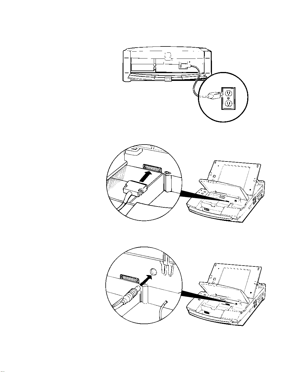
Setting up the 9790 Programmer
Figure 1-2. Power cord
Programmer basics
Figure 1-3. Programming head
Figure 1-4. ECG cable
Kappa 900/800 Series Pacemaker Programming Guide 1-3
Programmer basics
Setting up the 9790 Programmer
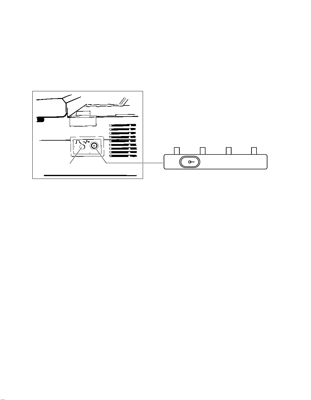
Calibrate Button
Connecting an external monitor/recorder
To connect an external monitor or recorder to your programmer, you need
the optional adaptor shown below. Connect the adaptor to the analog
output port on the right side of the programmer.
Connector Type: BNC
Output Signal: ± 1 Volt or ± 5mV (switchable)
Signal Output Adaptor
ABCD
± 1V ± 5mV
Connecting Optional Adaptor to the Analog Output
Port on the Programmer.
Figure 1-5. Connecting the optional external adaptor
Adaptor Output Signals (after model selection):
A - Patient’s ECG (upper most ECG on display)
B - Telemetered EGM (uppermost EGM on display)
C - Telemetered EGM (other EGM if programmed)
D - Marker Channel Telemetry
1-4 Kappa 900/800 Series Pacemaker Programming Guide

Setting up the 9790 Programmer
Programmer basics
Using the Calibrate button
Selecting the Calibrate button located next to the analog output port adds
a reference signal (as shown in Figure 1-6 and Figure 1-7) to the trace of
Marker Channel and EGM telemetry.
The Marker Channel signal shows the relative marker amplitudes, which
are not annotated with character codes on an external device. The EGM
calibration signal acts as a voltage reference for the displayed EGM.
Atrial Pace (AP)
Atrial Sense (AS)
Atrial Refractory Sense (AR)
Vent. Refractory Sense (VR)
Vent. Sense (VS)
Vent. Pace (VP)
Figure 1-6. Marker Channel Signals
5 mV
1 mV
Figure 1-7. EGM calibration signals
Kappa 900/800 Series Pacemaker Programming Guide 1-5

Programmer basics
Connecting the programmer to skin electrodes
Connecting the programmer to skin electrodes
At the start of a patient session, the programmer must be connected to
skin electrodes on the patient. The ECG display and measurement
functions will not operate without detection of the surface ECG signal.
Use an electrode lead to connect each skin electrode to the appropriate
port on the ECG cable. Typical electrode placement is shown below. Use
standard procedures for attaching disposable skin electrodes to the
patient.
RA (R)
RL (N)
Figure 1-8. Connecting the programmer to skin electrodes
Refer to the guide, Programmer Description and Setup, supplied with your
9790 programmer for more details on this procedure.
LA (L)
C (C)
LL (F)
( ) = IEC Coding
1-6 Kappa 900/800 Series Pacemaker Programming Guide

Positioning and using the programming head
Programmer basics
Positioning and using the programming head
In many of the procedures described in the following chapters, you will be
directed to position the programming head over the patient’s pacemaker.
When to position the programming head
You must position the programming head over the patient’s pacemaker
whenever a procedure initiates communication between the programmer
and pacemaker. Examples are:
■
At the start of a patient session when you select the [Auto-Identify]
or [Start] button. The programmer automatically initiates an
interrogation that takes a number of seconds to complete.
■
Prior to executing any command that results in a telemetry or
programming transmission.
■
To view or record Marker Channel or EGM telemetry.
Caution: Do not position the programming head over an implanted
pacemaker during electrocautery or defibrillation procedures.
To position the programming head
♦
The programming head must be properly positioned as described below.
An incorrectly positioned programming head can result in the failure of a
transmitted command and the loss of telemetry.
1. Hold the programming head directly against the patient’s skin with
the face of the programming head parallel to the pacemaker.
Figure 1-9. Positioning the programming head
Kappa 900/800 Series Pacemaker Programming Guide 1-7
Programmer basics
Positioning and using the programming head
2. Position the programming head so that the amber light in the light
array goes out and one or more of the green lights come on. Move
the head a little in each direction to find the position that lights the
greatest number of green lights. This is the optimum position.
Light Array
Figure 1-10. Light array indicator
Green
Amber/Green
Effect of the programming head on pacemaker operation
If model selection and application (software) loading are complete,
positioning the programming head over a Kappa 900/800 Series
pacemaker does not put the pacemaker in the magnet mode of operation.
The programmer automatically sends a Cancel Magnet command to the
pacemaker, which causes it to continue to operate as programmed.
An exception to this operation can occur if the programming head does
not establish a telemetry link with the pacemaker (because of strong
electrical interference or because the programming head is improperly
positioned). In such cases, positioning the programming head would
result in magnet mode operation until a telemetry link is established. You
can easily verify the present pacing mode by observing the Status Line at
the top of the screen.
The present pacing mode
shows in the status bar at the
1-8 Kappa 900/800 Series Pacemaker Programming Guide
top of the screen.

Positioning and using the programming head
Pacemaker operation returns to its programmed state about 2 seconds
after you remove the programming head from its position over the
pacemaker.
Programmer basics
Observing magnet mode operation
To observe magnet mode operation during a patient session, you must
conduct the Magnet test described in Chapter 2. Initiating the Magnet test
results in a Threshold Margin Test (TMT) and causes the pacemaker to
operate in the magnet mode.
Note: Between patient sessions before you select the pacemaker model,
positioning the programming head over a Kappa 900/800 Series
pacemaker will result in magnet mode operation.
Alternative PROGRAM and
INTERROGATE buttons
To initiate the Program and Interrogate commands, you have the option to
use the on-screen [Program] and [Interrogate] buttons or the Program
[P] and Interrogate [I] buttons on the programming head.
Light Array
[Interrogate] Button
Figure 1-11. Alternative Program and Interrogate
programming head buttons
Note: The [P] or [I] button on the programming head is active only when
its counterpart is displayed as an active button on the display screen.
Kappa 900/800 Series Pacemaker Programming Guide 1-9
[Program] Button
Programmer basics
Positioning and using the programming head
Automatic interrogation at the start of a session
At the start of a session when you select [Start] or [Auto Identify], the
programmer automatically interrogates the patient’s pacemaker for most
of the data contained within the pacemaker. For this process, you must
position the programming head and hold it steady in place until the
interrogation is complete.
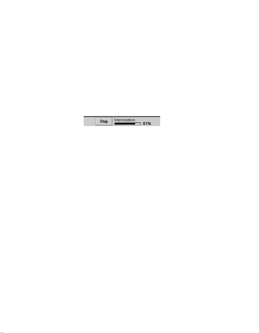
At the bottom center of the screen you will see an indicator showing the
progress of the interrogation. Because this interrogation retrieves most of
the data stored in the pacemaker, the process may take about a minute.
1-10 Kappa 900/800 Series Pacemaker Programming Guide

The display screen
The programmer display screen is an interactive device that not only
displays information in the form of both text and graphics, but functions as
a control panel by displaying buttons and menu options that you can
select using the stylus.
Features and conventions of the
display screen
This section describes the features and conventions of the display screen.
The Therapy Parameters screen below shows the main elements of the
typical screen.
Status Bar
Live Rhythm
Monitor Window
Programmer basics
The display screen
Task area
Command Bar
Active Field Button Tool Palette
Figure 1-12. Main elements of a display screen
Note: For information on changing the language in the screens (for
example, from English to German), see “Selecting system
operating preferences” on page 10-2.
Kappa 900/800 Series Pacemaker Programming Guide 1-11

Programmer basics
The display screen
Status Bar
The status bar
The status bar at the top of the screen shows:
■
The present pacing mode.
■
When any one of a number of test conditions is occurring.
■
The pacemaker model.
The Live Rhythm Monitor window
This window is a partial view of the full-screen display of ECG, Marker
Channel, and telemetered EGM waveform traces. You can expand this
window to its full size by selecting the small square button in the upperright corner of the window or by selecting the [Adjust...] button.
■
Heart rate and rate interval show if the programming head is
positioned over the pacemaker.
■
Annotations above the waveform trace show the point of
programmed parameter changes.
Live Rhythm Monitor Window
The waveform trace or traces that show in this window depend on the
selected task screen and how traces have been arranged in the fullscreen view. Refer to “Viewing the patient’s ECG and EGM traces” on
page 4-1 for information about the live rhythm monitor.
The task area
The portion of screen between the live rhythm monitor window at the top
and the command bar at the bottom changes according to the task or
function you select. The example in Figure 1-12 shows the Therapy
Parameters screen for programming pacemaker parameter settings. This
task area would appear much different if you selected, for example, the
Threshold Test Setup screen.
1-12 Kappa 900/800 Series Pacemaker Programming Guide
Active fields show as
unshaded areas on
the screen.
Programmer basics
The display screen
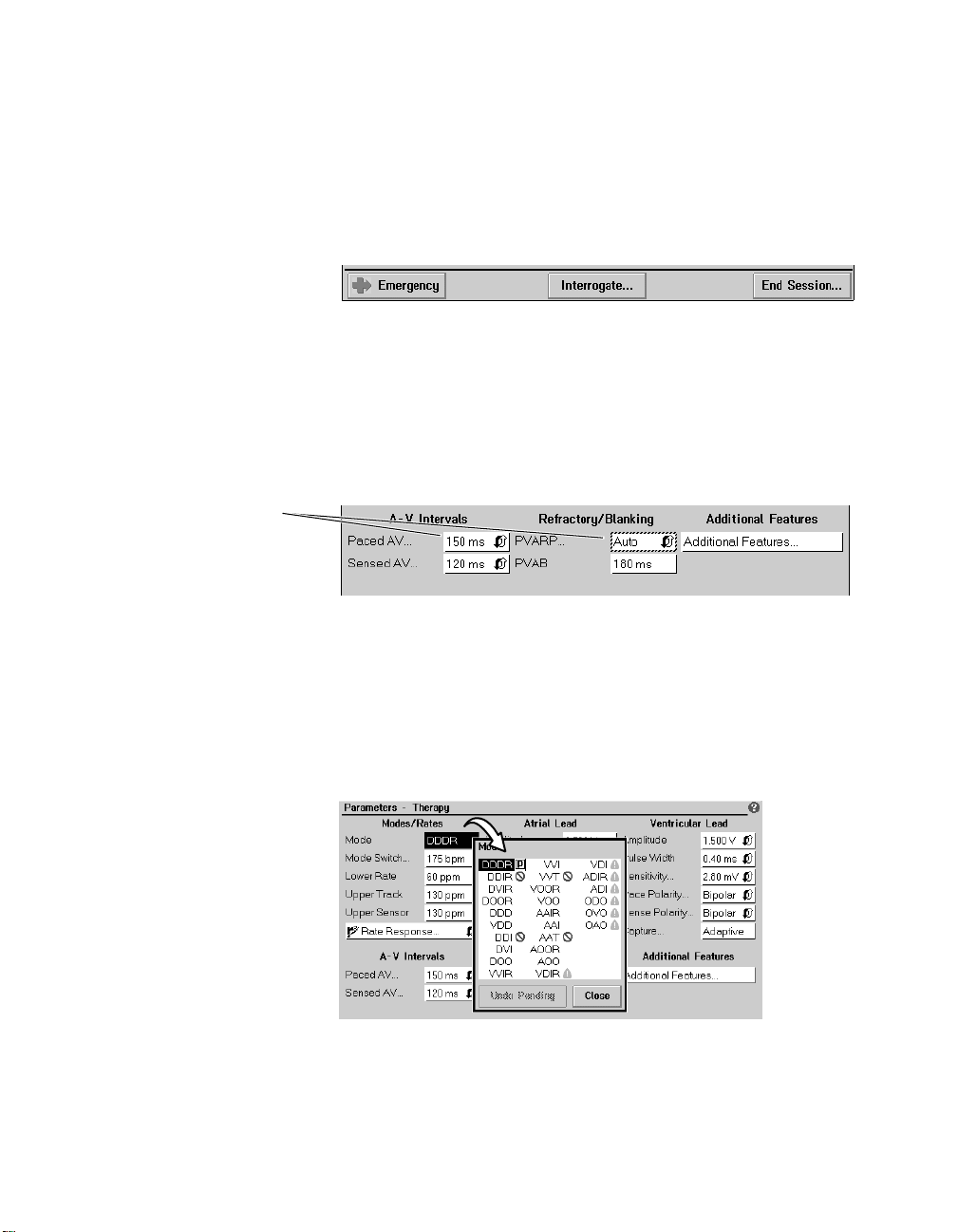
The command bar
The bar at the bottom of the screen always shows the command buttons
for programming “emergency” parameters settings, interrogating the
pacemaker, and ending the patient session.
For complete information on these functions, see “Programming
Emergency parameters” on page 1-18, “Interrogating the pacemaker” on
page 2-16, and “Ending a patient session” on page 2-37.
Active fields
Unshaded areas, or boxes, appearing in the task area are “active fields”
that respond to the stylus.
Selecting a value, word, name, or phrase that appears in an active field
opens a menu or window of alternative options for whatever is
represented in that field.
Selecting an active field
opens a menu or window of
alternative options, or in
some cases, an on-screen
keyboard.
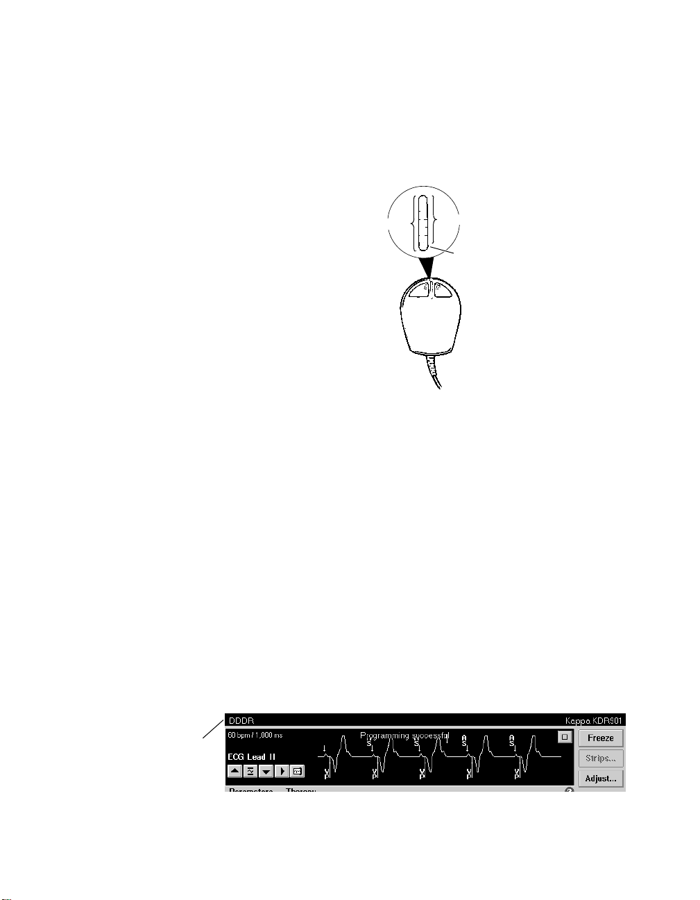
For example, touching the mode value “DDDR” in the Mode field with the
tip of the stylus opens a window of mode options. Selecting any one of
these options replaces the original DDDR value with the selected one,
which becomes a pending value.
Kappa 900/800 Series Pacemaker Programming Guide 1-13
Programmer basics
The display screen
Buttons having a less
distinct shaded label are
not presently active.
Selecting some fields (those with terms ending in an ellipsis, such as
“Rate Response...”) opens a window displaying additional fields. Some
fields that require entry of information, such as patient data, open an onscreen keyboard. How to use this keyboard is described later in this
section.
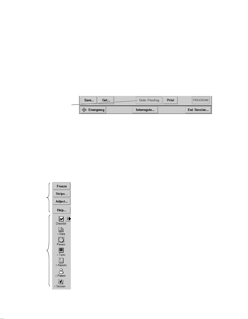
Buttons
Buttons like those shown below let you operate the programmer using the
stylus. You can “press” a button by touching it with the tip of the stylus.
Buttons may directly execute a command, such as the [Program] button,
or they may open a window that prompts another action. Usually such
buttons have a label ending with an ellipsis, such as the [Save...] or
[Get...] buttons shown above.
A procedure may instruct you to “press and hold” a button. In such cases
you should touch the tip of the stylus to the button and continue to
maintain pressure against the button until it is time to “release” the button.
The tool palette
The collection of buttons and icons along the edge of the screen is
referred to as the “tool palette.” These are the controls you will use to
Buttons
Icons
1-14 Kappa 900/800 Series Pacemaker Programming Guide
choose the task or function screen you want displayed. Once you have
started a patient session, the tool palette is always displayed, making it
quick and easy to move to the desired task or function.
Each of the icons acts like a button. To select an icon, touch the icon with
the stylus. The “<” symbol adjacent to some of the icons indicates that
selecting one of these icons opens a menu of related options. The icons
without the < symbol directly open a task screen.
Refer to Table 2-1 on page 2-6 for a brief explanation of the purpose of
each button and icon in the tool palette.
Note: If the programmer is operating in the Demo mode, the Session icon
is replaced with the Demo icon.
Programmer basics
The display screen
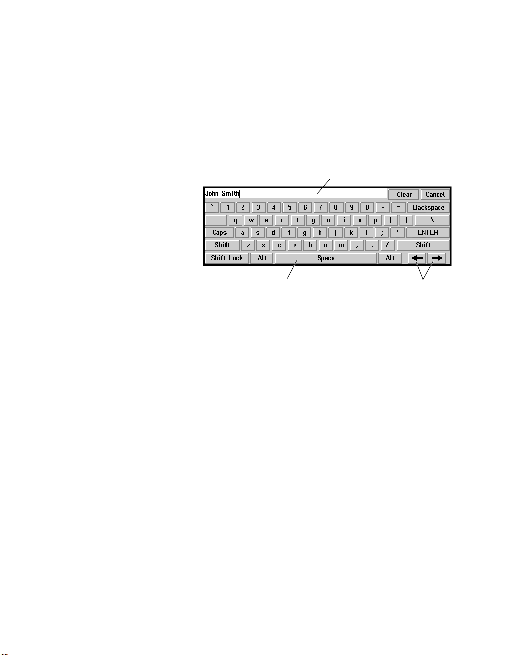
Using the on-screen keyboard
Certain fields on the screen allow you to enter data, such as the patient’s
name or chart number. Selecting such a field automatically displays the
on-screen keyboard shown below. By touching the letter or character
buttons with the stylus, you can use this display feature like an actual
keyboard.
Text Entry Window
Space Bar
Figure 1-13. Keyboard screen
The function of the on-screen keyboard buttons are very similar to the
keys on a computer keyboard or typewriter (see “Keyboard buttons” on
page 1-16).
Cursor
Position Keys
Kappa 900/800 Series Pacemaker Programming Guide 1-15

Programmer basics
The display screen
Tab le 1- 1. Keyboard buttons
Button or Feature Function
Text entry window
(See Figure 1-13)
Shows the text as you enter it using the keyboard.
You can enter only as many characters as can fit in
the selected field.
Clears all characters from the text entry window.
Closes the keyboard screen without changing the
selected field.
Deletes the character to the left of the cursor in the
text entry window.
Not intended for use.
Space Bar
(See Figure 1-13)
Locks all characters into upper case until the
key is selected again. While the
[Shift] and [Shift Lock] keys operate as
the
described below except that characters will shift to
lower case.
Shifts all of the characters into upper case and
replaces the top row of numbers with commonly used
symbols. This shift cancels automatically after you
select a character or symbol.
Locks all of the characters into upper case and
replaces the top row of numbers with commonly used
symbols. Press this key again to return to number
keys and lower case.
Shifts the keyboard to a limited set of characters.
Selecting a character or symbol cancels
Inserts a blank space.
Moves the cursor one space to the left or the right.
Closes the keyboard screen and enters the text in the
text entry window into the selected field.
[Caps] key is down,
[Caps]
[Alt] key.
1-16 Kappa 900/800 Series Pacemaker Programming Guide

Programmer basics
The display screen
Audible tones
Certain events in the operation of the programmer result in an audible
signal. The following tones alert the user to the success or failure of an
action.
■
A two-tone beep (low-to-high) indicates confirmation of an
Interrogate or a Program command.
■
A single low-tone beep indicates that an Interrogate, Program, or
Emergency command was not confirmed. It can also indicate that
the selected command cannot be executed.
■
A single, short beep coincides with pressing the Interrogate or the
Program button. It also occurs upon automatic identification of the
pacemaker.
Kappa 900/800 Series Pacemaker Programming Guide 1-17
Programmer basics
Programming Emergency parameters
Programming Emergency parameters
The Emergency programming command is a safety feature that overrides
all other functions and immediately programs the pacemaker to preset
emergency values intended to provide pacing support under a variety of
conditions. This programming cancels any temporary function in effect
and restores Magnet mode operation.
Note: Use of the Emergency command will clear the Ventricular Chronic
Lead Trend and Capture Management Trend diagnostic data collected by
the pacemaker. If “Collected Data” has been interrogated previously
during the session, this data will be available for viewing and printing until
the session ends. Collection of new trend data starts after you end the
session.
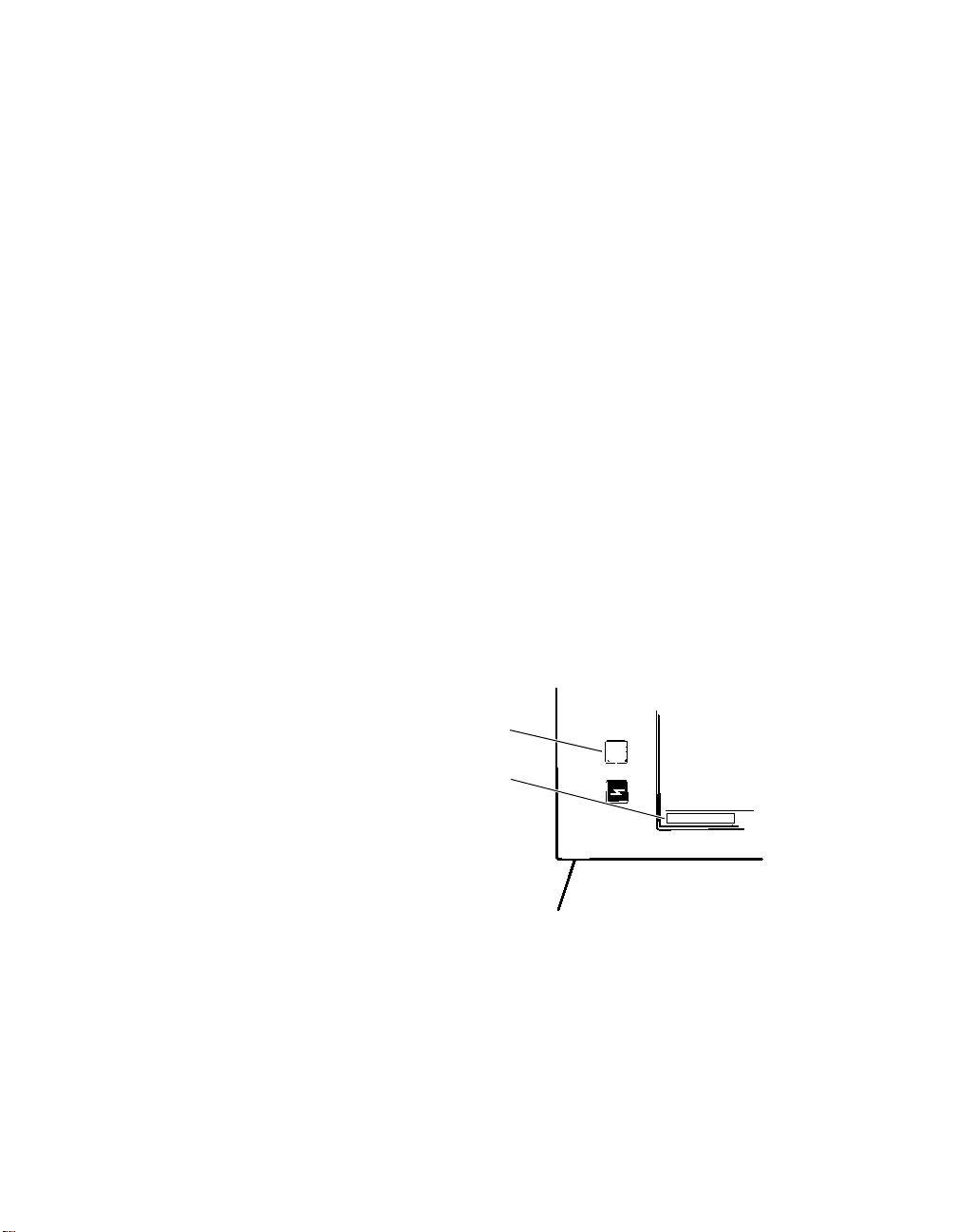
To program Emergency parameters
♦
1. Position the programming head over the pacemaker.
2. Take either of the following actions:
■
Press the square red button on the left side of the
display panel.
■
Or, select the on-screen [Emergency] button in the lower left
corner of the screen.
Emergency values are programmed
settings that provide higher-than-normal
energy output. It is not intended that
the pacemaker be left at these settings.
Refer to the Kappa 900/800 Series
Pacemaker Reference Guide for a list of
Emergency parameters settings forKappa
900/800 Series pacemakers.
Red button
Emergency button
3. Hold the programming head steady until a confirmation message
appears. If programming is not confirmed, verify that the
programming head is properly positioned and then reselect the
[Emergency] button or the square red button.
1-18 Kappa 900/800 Series Pacemaker Programming Guide
+
Emergency
 Loading...