

Medtronic guardian 2 link User Manual

MP6025871-12C1 / A
Transmitter
Transmetteur
Transmitter
Transmisor
Zender
Trasmettitore
Sender
Lähetin
Sändare
Sender
Transmissor
Transmissor
RELEASED

MP6025871-12C1 / A
RELEASED

MP6025871-12C1 / A
Contacts:
Africa: Medtronic Africa (Pty) Ltd.
Tel: +27 (0) 11 677 4800
Argentina: Corpomedica S.A.
Tel: +(11) 4 814 1333
Medtronic Directo 24/7: +0800 333 0752
Colombia: Medtronic Latin America Inc. Sucursal
Colombia
Tel: +(1) 742 7300
Medtronic Directo 24/7 (Landline): +01 800 710
2170
Medtronic Directo 24/7 (Cellular): +1 381 4902
Australia: Medtronic Australasia Pty. Ltd.
Tel: 1800 668 670 (product orders)
Tel: 1800 777 808 (customer help)
Azerbaijan: Isomed
Tel: +994 (12) 464 11 30
Bangladesh: Sonargaon Healthcare Pvt Ltd.
Mobile: (+91)-9903995417
or (+880)-1714217131
Belarus: ОДО “Баджин”
Tel: +375 17 313 0990
België/Belgique: N.V. Medtronic Belgium S.A.
Tel: 0800-90805
Bosnia and Herzegovina: Medimpex d.o.o.
Tel: +387 33 476 444
or +387 33 476 400
Fax: +387 33 476 401
or +387 33 432 241
Brasil: Medtronic Comercial Ltda.
Tel: +(11) 2182-9200
Medtronic Directo 24/7: +0800 773 9200
Bulgaria: R SR Ltd.
Tel: +359 885 428 900
Canada: Medtronic of Canada Ltd.
Tel: 1-800-284-4416 (toll free/sans-frais)
Chile: Medtronic Chile
Tel: +(9) 66 29 7126
Medtronic Directo 24/7: +1 230 020 9750
Medtronic Directo 24/7 (From Santiago): +(2)
595 2942
China: Medtronic (Shanghai) Ltd.
24 Hour Help (Cell): +86 400-820-1981
24 Hour Help (Landline): +86 800-820-1981
RELEASED
Croatia: Medtronic Adriatic d.o.o.
Tel: +385 1 488 11 20
Fax: +385 1 484 40 60
Danmark: Medtronic Danmark A/S
Tel: +45 32 48 18 00
Deutschland: Medtronic GmbH
Geschäftsbereich Diabetes
Telefon: +49 2159 8149-370
Telefax: +49 2159 8149-110
24-Stdn-Hotline: 0800 6464633
Eire: Accu-Science LTD.
Tel: +353 45 433000
España: Medtronic Ibérica S.A.
Tel: +34 91 625 05 42
Fax: +34 91 625 03 90
24 horas: +34 900 120 330
Europe: Medtronic Europe S.A. Europe, Middle
East and Africa Headquarters
Tel: +41 (0) 21-802-7000
France: Medtronic France S.A.S.
Tel: +33 (0) 1 55 38 17 00
Hellas: Medtronic Hellas S.A.
Tel: +30 210677-9099
Hong Kong: Medtronic International Ltd.
Tel: +852 2919-1300
To order supplies: +852 2919-1322
24-hour helpline: +852 2919-6441
ndia Medtronic Pvt. Ltd
India: I
Tel: (+91) Mobile: (+91)-9611633007
Indonesia: Medtronic International Ltd.
Tel: +65 6436 5090
or +65 6436 5000
80-22112245 / 32972359

MP6025871-12C1 / A
Israel: Agentek
Tel: +972 3649 3111
Italia: Medtronic Italia S.p.A.
Tel: +39 02 24137 261
Fax: +39 02 24138 210
Servizio assistenza tecnica:
Nº verde 24h: 800 20 90 20
Japan: Medtronic Japan Co. Ltd.
Tel: +81-3-6430-2019
24 Hr. Support Line: 0120-56-32-56
Kazakhstan: Medtronic BV in Kazakhstan
Tel: +7 727 311 05 80 (Almaty)
Tel: +7 717 224 48 11 (Astana)
Круглосуточная линия поддержки: 8 800 080
5001
Latin America: Medtronic, Inc.
Tel: 1(305) 500-9328
Fax: 1(786) 709-4244
Latvija: Ravemma Ltd.
Tel: +371 7273780
Macedonia: Alkaloid Kons Dooel
Tel: +389 2 3204 430
Magyarország: Medtronic Hungária Kft.
Tel: +36 1 889 0688
Malaysia: Medtronic International Ltd.
Tel: +603 7946 9000
Middle East and North Africa: Regional Office
Tel: +961-1-370 670
New Zealand: Medica Pacifi ca
Phone: 64 9 414 0318
Free Phone: 0800 106 100
Norge: Medtronic Norge A/S
Tel: +47 67 10 32 00
Fax: +47 67 10 32 10
Philippines: Medtronic International Ltd.
Tel: +65 6436 5090
or +65 6436 5000
Poccия: ООО «Медтроник»
Tel: +7 495 580 73 77
Круглосуточная линия поддержки: 8 800 200 76
36
Polska: Medtronic Poland Sp. Z.o.o.
Tel: +48 22 465 6934
Portugal: Medtronic Portugal Lda
Tel: +351 21 7245100
Fax: +351 21 7245199
Puerto Rico: Medtronic Puerto Rico
Tel: 787-753-5270
Republic of Korea: Medtronic Korea, Co., Ltd.
Tel: +82.2.3404.3600
man
ia: Medtronic BV Reprezentanta
Ro
Tel: +40 372 188 000
RELEASED
Schweiz: Medtronic (Schweiz) AG
Tel: +41 (0)31 868 0160
24-Stunden-Hotline: 0800 633333
Fax Allgemein: +41 (0)318680199
Montenegro: Glosarij
Tel: +382 20 642 495
Fax: +382 20 642 540
México: Medtronic Servicios S. de R. L. de C.V.
Tel (México DF): +(11) 029 058
Tel (Interior): +01 800 000 7867
Medtronic Directo 24/7 (from México DF):
+(55) 36 869 787
Medtronic Directo 24/7: +01 800 681 1845
Nederla nd, Luxembour g: Medtronic B.V.
Tel: +31 (0) 45-566-8291
Gratis: 0800-3422338
Serbia: Medtronic B.V. Serbia
Tel: +381 11 2095 900
Singapore: Medtronic International Ltd.
Tel: +65 6436 5090
or +65 6436 5000
Slovenija: Zaloker & Zaloker d.o.o.
brezplačna številka: 080 1880
Tel: +386 1 542 51 11
Slovenská republika: Medtronic Slovakia, s.r.o.
Tel: +421 26820 6942
HelpLine: +421 26820 6986

MP6025871-12C1 / A
Sri Lanka: Swiss Biogenics Ltd.
Mobile: (+91)-9003077499
or (+94)-777256760
Suomi: Medtronic Finland Oy
Tel: +358 20 7281 200
Help line: +358 400 100 313
Sverige: Medtronic AB
Tel: +46 8 568 585 20
Fax: +46 8 568 585 11
Taiwan: Medtronic (Taiwan) Ltd.
Tel: 02-21836000
Toll free: +886-800-005285
Thailand: Medtronic (Thailand) Ltd.
Tel: +662 232 7400
Türkiye: Medtronic Medikal Teknoloji
Ticaret Ltd. Sirketi.
Tel: +90 216 4694330
USA: Medtronic Diabetes Global Headquarters
24 Hour HelpLine: +1-800-646-4633
To order supplies: +1-800-843-6687
Ukraine: Medtronic B.V. Representative office in
Ukraine
Tel: +38 044 392 04 01
Лінія цілодобової підтримки:
0 800 508 300
United Kingdom: Medtronic Ltd.
Tel: +44 1923-205167
Österreich: Medtronic Österreich GmbH
Tel: +43 (0) 1 240 44-0
24 – Stunden – Hotline: 0820 820 190
Česká republika: Medtronic Czechia s.r.o.
Tel: +420 233 059 401
Non-stop helpLine:
+420 233 059 059
RELEASED

MP6025871-12C1 / A
RELEASED
MP6025871-12C1 / A
The Guardian™ 2 Link transmit ter is a component of the continuous glucose
monitoring system for the MiniMed
from the Enlite™ glucose sensor. Th e transm itte r the n wir ele ss ly sen ds the data to
the insulin pump.
™
640G insulin pump. The transmitter collects data
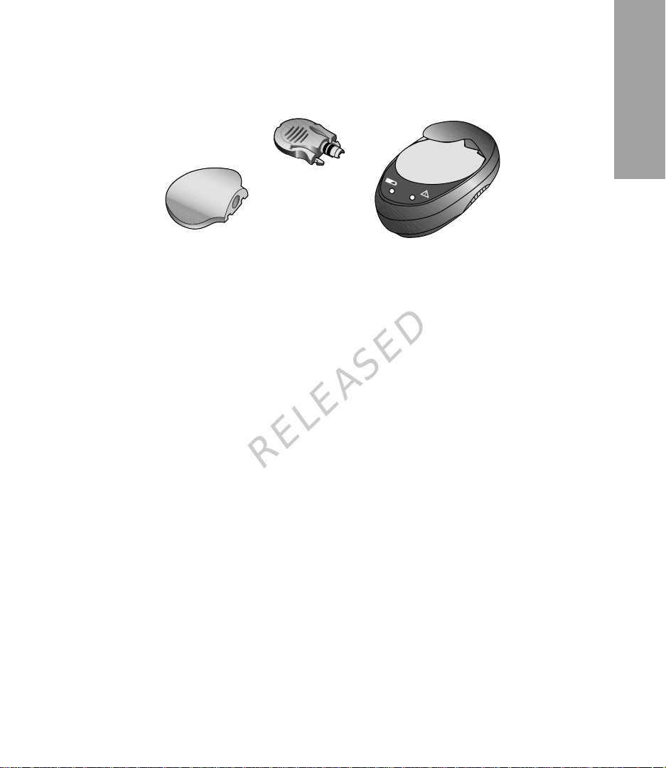
Guardian 2 Link transmitter kit components
A complete Guardian 2 Link transmitter kit includes the following components:
• Guardian 2 Link transmitter (MMT-7731)
•
Watertight Tester (MMT-7726)
Charger (MMT-7715)
•
•
One-press serter (MMT-7512)
Indications for use
The transmitter is indicated for single-patient use as a component of select Medtronic
continuous glucose sen si ng s ystems and MiniMed sensor-en abl ed p um p syst em s.
Contraindications
Do not expose your transmitter to MRI equipment, diathermy devices, or other
devices that generate st ro ng mag neti c fi eld s. If your tra ns mit ter is ina dvertently
exposed to a strong magnetic field, discontinue use and contact the 24 Hour
HelpLine or your local represen tati ve for further assistance .
RELEASED
English
Warnings
This product contains small parts and may pose a choking hazard for young children.
If the tester comes in contact with blood, the tester must be discarded. Dispose of the
tester according to the local regu lat ion s for medi ca l was te dis pos al .
Bleeding may occur after inserting the sensor. Make sure that the site is not bleeding
before connecting the transmitter to the sensor. If bleeding occurs, apply steady
pressure with a sterile gauze or clean cloth at the insertion site until bleeding stops.
After bleeding stops, conne ct the tr ans mi tter to the sens or.
Contact the 24 Hour HelpLine or your local representative if you experience any
adverse reaction s as sociated with the transmit ter or se nso r.
-1-

MP6025871-12C1 / A
Magnetic fields
Do not expose your transmitter to MRI equipment, diathermy devices, or other devices
that generate strong magnetic fields. If your transmitter is inadvertently exposed to a
strong magnetic field, discontinue use and contact the 24 Hour HelpLine or your local
representative for fur ther assis tan ce .
X-rays, MRIs, diathermy devices, and CT scans
If you are going to have an x-ray, diathermy treatment, CT scan, MRI or other type of
exposure to radiation , rem ove your sensor and transmitter be for e ente ri ng a roo m
containing any of these equipme nt.
Important information about airport security systems, and using your transmitter on an
airplane, can be found on the Emergency Card. Be sure to carry the Emergency Card
provided with your device when you are traveling.
Precautions
Refer to the Enlite Sensor User Guide for all precautions, warnings, and instructions
relating to the sensor.
Always use the tester when cleaning the transmitter. Do not use any other test plug wi th
the transmitter.
Do not twist the tester or sensor while attached to the transmitter. This will damage the
transmitter.
Do not allow water, or any other liquid, to come in contact with the tester when it is not
connected to the transmitter. A wet tester can cause damage to the transmitter.
Do not allow the transmitter to come in contact with any liquid when not connected to a
sensor or to the tester.
Do not clean the o-rings on the tester, as this can damag e the o-r in gs.
RELEASED
Notice
Caution: Any changes or modifications to the devi ces no t expre ssly appr ov ed by
Medtronic Diabetes could interfere with your ability to operate the
equipment, cause injury, and void your warranty.
Radio Frequency (RF) communication
This device complies with the United States Federal Communicat ion s Com mi ss io n (FCC)
and international stan dards for el ectromagnetic compatibil ity.
-2-

MP6025871-12C1 / A
This device complies with Part 15 of t he FCC Rules. Operation is subject to the
following two conditions: (1) This device may not cause harmful interference, and (2)
this device must accept any interference received, incl uding interference that may
cause undesired operation.
These standards are designed to provide reasonable protection against excessive
radio frequency interference, and prevent undesirable operation of the devices from
unwanted electromagnetic interference.
This equipment has been tested and found to comply with the limits for a Class B
digital device, pursuan t to Par t 15 of the FCC rules. T hes e lim its are desi gne d to
provide reasonable prote cti on ag ain st har m ful in ter fer enc e in a resi dential
installation. This equipm ent generates, uses, and can radiate ra di o freq uen cy ener gy
and, if not installed and used in accordance with the instructions, may cause harmful
interference to radio com mun ic atio ns . Howe ve r, ther e is no guarantee that
interference will not occur in a particular installation. If this equipment does cause
harmful interference to radio or television reception, which can be determined by
turning the equipment off and on, the user is encouraged to try to correct the
interference by one or more of the following measures:
• Reorient or relocate the receiving antenna.
• Increase the separation between the equipment and the receiver.
This device can generate, use, and radiate radio frequency energy and, if installed
and used in accordance with the instructions, may cause harmful interference to
radio communications. If the device does cause interference to radio or television
reception, you are encouraged to try to correct the interference by one or more of the
following measures:
• Decrease the distance between the transmitter and the insulin pump to 1.8
meters (6 feet) or less.
• Increase the separation between the transmitter and the device that is receiving/
emitting interference.
If other devices that employ radio frequencies are in use, such as cell phones,
cordless phones, and wireless networks, they may prevent communication between
the transmitter and the insulin pump . Thi s interference does not cause any inc orr ect
data to be sent and does not cause any harm to your devices. Moving away from, or
turning off, these other device s may enabl e co mmunication. If you continue to
experience RF interference, please contact your local representative.
Caution: Changes or modifications to the internal RF transmitter or antenna
not expressly approved by Medtronic could void the user's
authority to operate this insu lin de live ry syst em .
RELEASED
English
-3-

MP6025871-12C1 / A
For Canada only
This device complies with Industry Canada licence-exempt RSS standard(s).
Operation is subject to the following two conditions: (1) this device may not cause
interference, and (2) this device must accept any interference, including
interference that may cause undesired operation of the device.
Le présent appareil est conforme aux CNR d'Industrie Canada applicables aux
appareils radio exempts de licence. L'exploitation est autorisée aux deux conditions
suivantes : (1) l'appareil ne doit pas produire de brouillage, et (2) l'appareil doit
accepter tout brouillage radioélectrique subi, même si le brouillage est susceptible
d'en compromettre le fonctionnement.
Directive 1999/5/EC
Medtronic declares that this product is in conformity with the essential requirements of
Directive 1999/5/EC on Radio and Telecommunications Terminal Equipment.
For additional information, contact Medtronic MiniMed at the address or phone number
provided on the back cover.
Assistance
Please contact your loca l rep resen tati ve for assis tanc e. Re fer to the Medtr oni c Di abet es
International Contacts li st at t he begi nni ng of thi s user gui de for cont act infor ma tion .
Charger
The transmitter contains a non- r epl ac eabl e, rec ha rge abl e ba tter y tha t you can rechar ge
as needed with the charger. The charger has a green light that shows the charging status
and a red light that communicates any problems during charging. If you see a red light,
see the Troubleshooting section. The charger needs one AAA alkaline battery.
Note: If the battery is installed incorrectly or is low, the charger will not work. Repeat the
battery installation steps using a new battery.
RELEASED
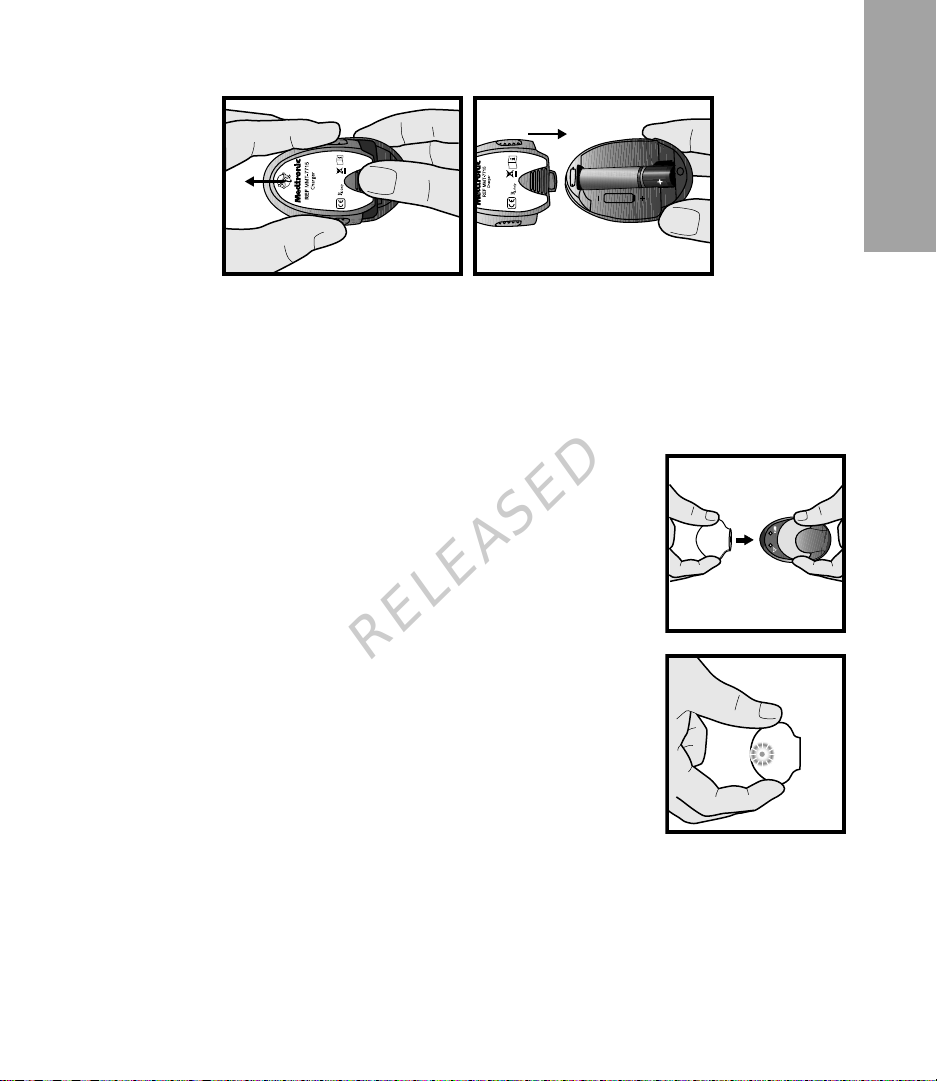
Installing a battery in the charger
To install a battery in the charger:
1
Push the battery cover in and slide it off (as shown in the following illustration).
2
Insert a new alkaline AAA battery. Make sure the + and - symbols on the battery align
with these same symbols shown on the charger.
-4-
MP6025871-12C1 / A
3 Slide the cover back on the charger unti l it clicks i nto plac e.
Charging the transmitter
Caution: Charge the transmitter after each sensor use. A fully charged
transmitter works at least six days without recharging. A depleted
transmitter can take up to one hour to recharge.
To charge the transmitter:
1
Connect the transmitter to the charge r by lini ng it up, fla t
side down, with the charger. Push the two compo nents
together fully.
2
Within 10 seconds after the transmitter is connected, a
green light on the charger will flash for one to two seconds
as the charger powers on. For the rest of the charging time,
the charger’s green light will continue to flash in a pattern of
four flashes with a pause between the four flashes.
3
When charging is complete, the green light on the charger
will stay on, without flashing, for 15 to 20 seconds and then
turn off.
4
After the green charger light turns off, disconnect the
transmitter from the charger. The green light on the
transmitter will flash for about five secon ds and then turn
off.
RELEASED
English
Inserting the sensor
Always refer to the serter user guide for instructions on how to insert the sensor.
-5-

MP6025871-12C1 / A
Connecting the transmitter to the sensor
Before proceeding, have your pump user guide available.
To connect the transmitter to the sensor:
1
After the sensor is inserted, consult your serter user guide for details on applying the
required overtape.
2
Hold the rounded end of the inserted sensor to prevent it from moving during
connection.
3
Hold the transmitter as shown. Line up the two notches on the
transmitter with the side arms of the sensor. The flat side of the
transmitter should face the skin.
4
Slide the transmitter onto the sensor until the sensor’s flexible
arms snap into the notches on the transmitter. If the transmitter
is properly connected, and if the sensor has had enough time to
become hydrated, the green light on the transmitter will flash
within 10 seconds.
5
If the transmitter light does not flash, disconnect the transmitter from the sensor, wait
for several seconds and then reconnect. If the transmitter light still does not flash,
charge the transmitter.
6
When the transmitter light flashes green when connected to the sensor, use your
pump to start the sensor. For more instructions, see your pump user guide.
7
After the transmitter successfully sends sensor data to the pump, attach the sensor's
adhesive tab to the transmitter.
8
Follow the instructions that appear on the pump screen or follow the instructions in
your pump user guide.
RELEASED
-6-

MP6025871-12C1 / A
Disconnecting the transmitter from the sensor
Before proceeding, have your pump user guide available.
To disconnect the transmitter from the sensor:
1
Carefully remove any oc cl usi ve dr ess in g fr om the
transmitter and sensor.
2
For the Enlite sensor, remove the adhesive tab from the top
of the transmitter.
3
Hold the transmitter as shown, and pinch the flexible side
arms of the sensor between your thumb and forefinger.
4
Gently pull the transmitter away from the sensor.
5
Follow the instructions that appear on the pump or follow
the instructions in your pump user guide.
Removing the sensor
Always refer to the sensor user guide for instructions on how to remove the sensor.
Bathing and swimming
After the transmitter and sensor are connected, they form a waterproof seal to a
depth of 2.4 meters (eight feet) for up to 30 minutes. You can shower and swim
without removing them. No occlusiv e dr essi ng or overtape is needed.
Watertight Tester
The tester is used to test the transmitter to make sure it is working. It is also used as
a required component for cleanin g the tr ansmi tter . Pr ope rl y c onn ec ting the teste r to
the transmitter will ensure that fluids do not come in contact with the transmitter’s
connector pins. Fluids ca n caus e co nnec tor pins to corrode and affect the
transmitter’s performance.
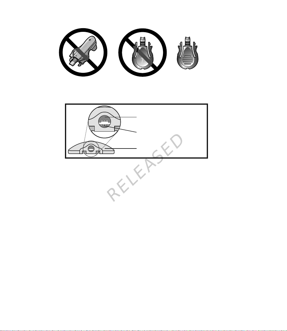
Do not twist the tester while attached to the transmitter. This will damage the
transmitter.
The tester can be used for one year. If you continue to use the tester for more than
one year, the transmitter's connector pins could be damaged, because the tester
cannot continue to provide a waterproof seal. For instructions on how to check the
connector pins, see Inspec ti ng the trans mit ter con nec tor pins, on page 8.
RELEASED
English
-7-
MP6025871-12C1 / A
Caution: Only use the tester with the transmitter. Do not use any other test plug.
i
Inspecting the transmitter connector pins
This image is an example of how the connector pi ns sh oul d look .
connector opening
connector pins
housing
Look inside the transmitter’s co nnec tor ope nin g to make sure that the connector pins are
not damaged or corroded. If the con nec tor pin s ar e dama ged or corro ded , the tran sm itte r
cannot communicate with the charger or pump. Contact the 24 Hour HelpLine or your
local representative. It may be time to replace your transmitter.
Also look for moisture inside the connector opening. If you see any moisture, allow the
transmitter to dry for at least one hour. Moisture inside the connector opening could
cause the transmitter to not work properly, and could cause corrosion and damage over
time.
RELEASED
✓
-8-
MP6025871-12C1 / A
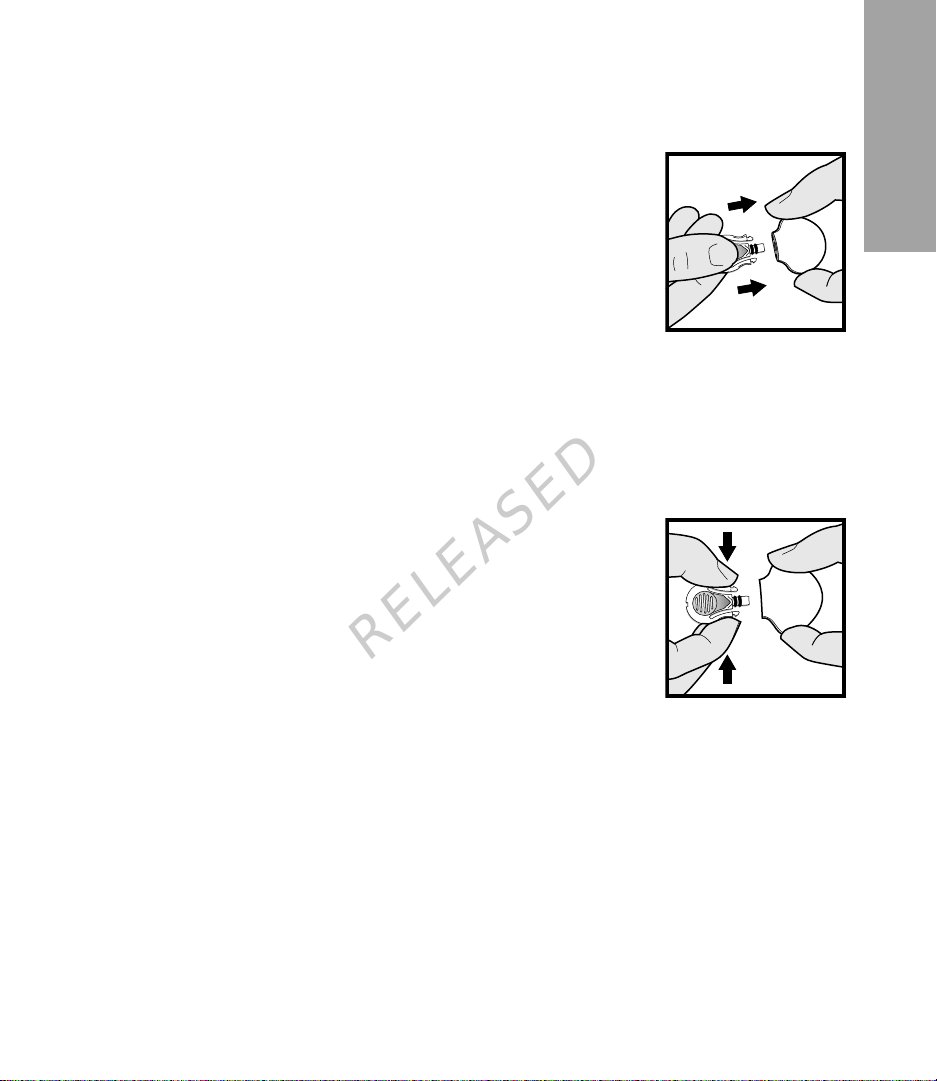
Connecting the tester for testing or cleaning
Before proceeding, have available your pump user guide.
To connect the tester:
1
Hold the transmitter and the tester as shown. Line up the
flat side of the tester with the flat side of the transmitter.
2
Push the tester into the transmitter until the flexible side
arms of the tester click into the notches on both sides of the
transmitter.
3
Within five seconds, when properly connected, the green
light on the transmitter flashes for about 10 seconds.
4
To test the transmitter, check the sensor icon on the pump
to ensure that the transmitter is sendi ng a sig nal (see you r pump use r gui de).
5
To clean the transmitter, see Cleaning the transmit ter , on page 9.
6
After testing or cleaning, disconnect the tester from the transmitter.
Disconnecting the tester
To disconnect the tester:
1
Hold the transmitter body as shown and pinch the side
arms of the tester.
2
With the tester arms pinched, gently pull the transmitter
away from the tester.
Note: To save transmitter battery life, do NOT leave the
tester connected after cleaning or testing.
RELEASED
English
Cleaning the transmitter
The transmitter is a single-p atie nt us e dev ice and not intended for multi-patient use.
Caution: Do not discard the transmitter in a medical waste container or
otherwise subject it to incineration. The transmitter contains a
battery that may explode upon incineration.
Note: The tester is a required component for cleaning the transmitter. For details,
see Watertight Tester, on page 7.
Always clean the transmitter after each use.
To clean the transmitter, you will need the following materials: mild liquid soap, a soft-
bristled toddler toothbrush, a container, 70% isopropyl alcohol, and a few clean, dry
cloths.
-9-

MP6025871-12C1 / A
Warning: Cracking, flaking, or damage of the housing are signs of deterioration
and the performance of the device may be compromised. This may
affect the ability to properly clean and disinfect the transmitter. If these
signs are noted, stop using the device and call the 24 Hour HelpLine or
your local representative. T he devi ce must b e dis car ded ac cord ing to
local regulations for battery disposal (non-incineration).
To clean the transmitter:
1
Attach the tester to the transmitter.
2
If optional occlusive dressing or overtape was used and there is adhesive residue on
the transmitter, see Removing adhesive residue, on page 10.
3
Rinse the transmitter under room temperature tap water for at least one minute, and
until visibly clean. Make sure all hard-to-reach areas are rinsed completely.
4
Prepare a mild liquid soap so luti on us in g 5 mill ili ter s ( 1 teas po on) of liqui d so ap per
3.8 liters (1 gallon) of room temperature tap water.
5
With tester still attached, submerge the transmitter in the cleaning solution and soak
for one minute.
6
Holding the tester, brush the entire sur fac e of the trans mi tter using a soft -bristled
toddler toothbrush. Make sure to brush all hard-to-reach areas until visibly clean.
7
Rinse the transmitter under running room temperature tap water for at least one
minute, and until all visible liquid soap is gone.
8
Dry the transmitter and tester with a clean, dry cloth.
9
Place the transmitter and tester on a clean, dry cloth and air dry them completely.
10
Disconnect the tester from the transmitter.
RELEASED
Removing adhesive residue
You may need to perform this procedure only if you have used optional occlusive
dressing, which may leave adhesive residue on the transmitter. If you visually inspect the
transmitter and see adhesive residue on it, follow the instructions below.
To remove adhesive residue, you will need the following materials: medical adhesive
remover (such as Det a ch ol
Note: During testing, Medtro nic Mi niM ed us ed Deta cho l to rem ov e the adhesiv e r es idu e
from the transmitter. Detachol is recommended for use but may not be available in
all countries.
To remove adhesive residue:
1
Make sure the tester is attached to the transmitter.
®
- which is a mineral spirit) and cotton swabs.
-10-

MP6025871-12C1 / A
2 Holding the tester, saturate a cotton swab in the Detachol solution and gently rub
the adhesive residue on the transmi tter unti l it is fully rem ove d.
3
Continue with the cleaning procedure. See Cleaning the transmitter, on page 9
for details.
Cleaning the charger
This procedure is for gen era l cl ean ing as required, based on physi ca l appearance.
Caution: The charger is NOT waterproof. Do NOT immerse in water or any
other cleaning agent.
Caution: Dispose the charger according to the local regulations for battery
disposal (non-incineration).
To clean the charger:
1
Wash your hands thoroughl y.
2
Use a damp cloth with mild cleaning solution, such as a dishwashing detergent,
to clean any dirt or foreign material from the outside of the charger. Never use
organic solvents, such as paint thi nner or ac eton e, to clean the charger.
3
Place the charger on a clean, dry cloth and air dry for two to three minutes.
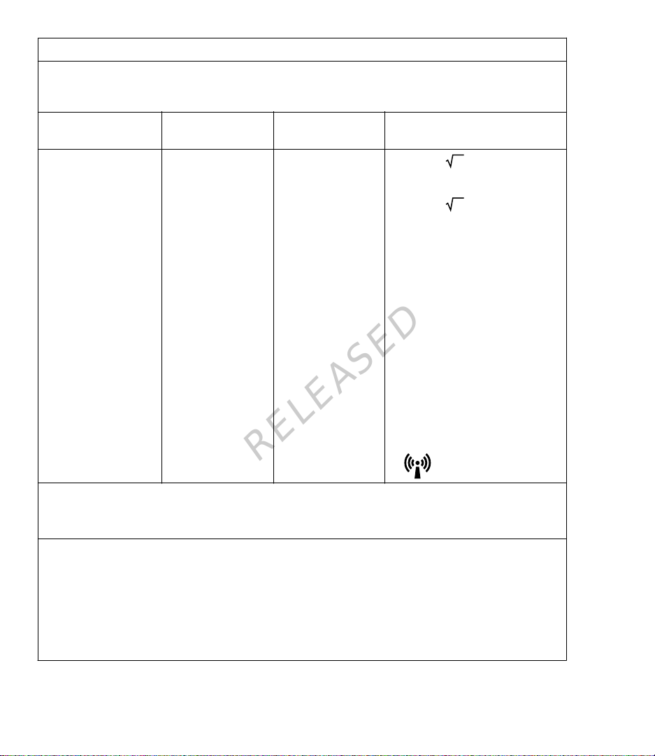
Troubleshooting
The following table contains troubleshooting information for the transmitter, charger,
and tester. For more informat ion about troub les ho otin g, s ee yo ur pump use r gu ide .
Problem Likely Cause(s) Resolution
You connected the
transmitter to the
charger and no lights
came on.
The transmitter connector pins are damaged or
corroded.
Your charger battery has
no power.
RELEASED
1 Check the transmitter connector pins for
damage or corrosion. For more information about your connector pins, see In-
specting the transmitter connector pins,
on page 8. If the pins are damaged or cor-
roded, contact the 24 Hour HelpLine or
your local representative. It may be time
to replace your transmitter.
2
If there is no damage to the connector
pins, replace the battery in the charger.
For instructions on replacing your charger
battery, see Installing a battery in the
charger, on page 4.
English
-11-

MP6025871-12C1 / A
Problem Likely Cause(s) Resolution
During charging, the
flashing green light on
the charger turns off
and you see a flashing
red light on the charger.
During charging, the
flashing green light on
the charger turns off
and you see a series of
quick flashing red lights
on the charger.
During charging, a mix
of quick and long flashing red lights appear
on the charger.
The green light on the
transmitter does not
flash when you connect it to the sensor.
Your charger battery is
low on power.
Your transmitter is low
on power.
Your charger and your
transmitter are low on
power.
Your transmitter is not
fully connected.
Your transmitter is low
on power.
Your sensor is not properly inserted into your
body.
RELEASED
Replace the battery in the charger. For instructions on replacing your charger battery, see In-
stalling a battery in the charger, on page 4.
1
Charge the transmitter continuously for
one hour. If flashing does not stop, proceed to step 2.
2
Charge the transmitter continuously for
eight hours. If flashing does not stop, call
the 24 Hour HelpLine or your local representative. It may be time to replace your
transmitter.
1
Replace the battery in the charger. For in-
structions on replacing your charger battery, see Installing a battery in the
charger, on page 4.
2
Charge the transmitter continuously for
one hour. If flashing does not stop, proceed to step 3.
3
Charge the transmitter continuously for
eight hours. If flashing does not stop, call
the 24 Hour HelpLine or your local representative. It may be time to replace your
transmitter.
1
Disconnect the transmitter from the sen-
sor.
2
Wait for five seconds and reconnect them.
If the green light still does not flash, proceed to step 3.
3
Fully charge the transmitter. If the green
light still does not flash, proceed to step 4.
4
The sensor may not be properly inserted
into your body. Insert a new sensor.
-12-

MP6025871-12C1 / A
Problem Likely Cause(s) Resolution
The green light on the
transmitter does not
flash when you connect it to the tester.
Your transmitter battery does not last for
six days.
Your transmitter has
lost connection with
your pump.
Your transmitter is low
on power.
Your transmitter is not
fully connected.
Your transmitter is not
fully charged when you
connect it to the sensor.
The transmitter and
pump frequently lose
wireless connection.
Your pump is out of
range.
There is RF interference
from other devices.
RELEASED
1 Check the connection between the trans-
mitter and the tester. If the green light still
does not flash, proceed to step 2.
2
Fully charge the transmitter.
3
Test the transmitter with the tester again.
If you still do not see the green light flash,
call the 24 Hour HelpLine or your local
representative. It may be time to replace
your transmitter.
1
Fully charge the transmitter before con-
necting it to the sensor. If the transmitter
battery still does not last for six days, proceed to step 2.
2
Move away from any device that can
cause RF interference. For more information on RF interference, see Radio Fre-
quency (RF) communication, on page 2.
3
Make sure your pump and your transmitter
are located on the same side of your body
to minimize any RF interference. If your
fully charged transmitter battery continues
to lose power before a full six days, call
the 24 Hour HelpLine or your local representative. It may be time to replace your
transmitter.
1
Move away from any device that can
cause RF interference. For more information on RF interference, see Radio Fre-
quency (RF) communication, on page 2. If
your transmitter is still not communicating
with your pump, proceed to step 2.
2
Make sure your pump and your transmitter
are located on the same side of your body
to minimize any RF interference. If your
transmitter is still not communicating with
your pump, call the 24 Hour HelpLine or
your local representative for assistance.
English
-13-

MP6025871-12C1 / A
Storing the devices
Store the transmitter, charger , an d teste r in a clean, dr y lo cation at room temperature. If
the transmitter is not in use, you must charge the transmitter at least once every 60 days.
Although not required, you may store the transmitter on the charger. If you are storing the
transmitter on the charger, you must disconnect and reconnect the charger and the
transmitter at least once every 60 days.
Disposal
Discard the transmitter according to local regulations for battery disposal.
Specifications
Biocompatibility Transmitter: Complies with EN ISO 10993-1
Applied parts Transmitter
Sensor
Operating conditions Transmitter temperature: -5 °C to 45 °C (23 °F to 113 °F)
Caution: When operating the transmitter on a tester in air temperatures
greater than 41 °C (106 °F), the temperature of the transmitter may exceed
43 °C (109 °F)
Transmitter relative humidity: 5% to 95% with no condensation
Transmitter pressure: 61.36 kPa to 106.17 kPa (8.9 psi to 15.4 psi)
Charger temperature: 10 °C to 40 °C (50 °F to 104 °F)
Charger relative humidity: 30% to 75% with no condensation
Storage conditions Transmitter temperature: -25 °C to 55 °C (-13 °F to 131 °F)
Transmitter relative humidity: 10% to 100% with condensation
Transmitter pressure: 61.36 kPa to 106.17 kPa (8.9 psi to 15.4 psi)
Charger temperature: -10 °C to 50 °C (14 °F to 122 °F)
Charger relative humidity: 10% to 95% with no condensation
Battery life Uses one new AAA battery to charge the transmitter.
Transmitter frequen-cy2.4 GHz, 2M65G1D modulation, less than 1mW ERP
RELEASED
Maximum output
power (EIRP)
-0.63 dBm
-14-

MP6025871-12C1 / A
Radio Frequency (RF)
communications
Transmitter expected
service life
Pump to transmitter frequency: 2.4 Ghz; proprietary Medtronic protocol;
range up to 1.8 meters (6 feet)
Utilizes the IEEE 802.15.4 protocol with proprietary data format
Operating frequency: 5 frequencies are used: 2420, 2435, 2450, 2465, and
2480 MHz
Bandwidth: 5 MHz, which is allocated channel bandwidth per IEEE protocol
The transmitter expected service life is 1 year depending on patient usage
Guardian 2 Link wireless communication
Quality of service
The Guardian 2 Link transmitter and the MiniMed 640G insulin pump are associated
as part of an 802.15.4 network for which the pump functions as the coordinator and
the transmitter as an end node. In an adverse RF environment the pump will assess
channel changing needs based on "noise" levels detected during an energy scan.
The pump will perform the energy scan if after 10 minutes no CGM transmitter signal
has been received. If the channel change occurs the pump will send beacons on the
new channel.
The Guardian 2 Link transmitter wi ll ini t ia te a chan nel searc h whe n beaco n dete cti on
fails on the associated channe l. T he se arc h wi ll be con duc ted acr os s all f ive
channels. When the beacon is locate d the t ransmitter will rejoin on the identi fie d
channel. Upon re-association any missed packets (up to 10 hours) will be transmitted
from the transmitter to the pump.
In normal operation the transmitter will transmit a packet every 5 minutes and
retransmit the packet if the data is corrupted or missed.
RELEASED
English
Data security
The MiniMed 640G insulin pump is designed to only accept radio frequency (RF)
communications fr om reco gni ze d and linked devices (you must pr ogr am your pump
to accept information from a specific device).
The MiniMed 640G insulin pump and system components (meters and transmitters)
ensure data security via proprietary means and ensures data integrity using error
checking processe s, s uc h as cycli c redundancy checks.
-15-

MP6025871-12C1 / A
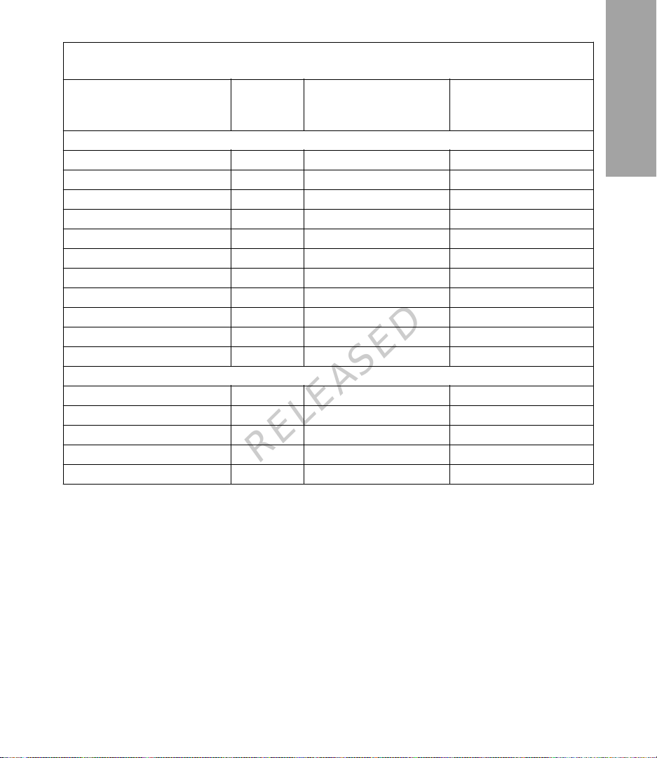
Guidance and manufacturer's declaration
Guidance and Manufacturer's Declaration - Electromagn etic Emiss ions
The Guardian 2 Link is intended for use in the electromagnetic environment specified
below. The customer or the user of the Guardian 2 Link should make sure that it is
used in such an environment.
Emissions Test Compliance Electromagnetic Environment - Guidance
RF emissions
CISPR 11
RF emissions
CISPR 11
Guidance and Manufacturer's Declaration - Electromagnetic Immunity
The Guardian 2 Link is intended for use in the electromagnetic environment specified
below. The customer or the user of the Guardian 2 Link should assure that it is used in
such an environment.
Immunity Test IEC 60601 Test Level Compliance
Electrostatic discharge
(ESD)
IEC 61000-4-2
Electrical fast transient/
burst
IEC 61000-4-4 ±1 kV for input/output lines
Surge
IEC 61000-4-5
Voltage dips, short in-
terruptions and voltage
variations on power
supply lines
IEC 61000-4-11
Group 1 The Guardian 2 Link must emit electromagnetic energy in order to
Class B The Guardian 2 Link is suitable for use in all establishments, in-
perform its intended function. Nearby electronic equipment may
be affected.
cluding domestic and those directly connected to the public lowvoltage power supply network that supplies buildings used for
domestic purposes.
Electromagnetic Envi-
±2 kV, ±4 kV, ±8 kV Air
±2 kV, ±4 kV, ±6 kV Indirect
RELEASED
±2 kV for power supply
lines
±1 kV line(s) to line(s)
±2 kV line(s) to earth
<5% U
(>95% dip in UT)
T
for 0.5 cycle
Level
±8 kV Air
±6 kV Indirect
±22 kV Air,
<5% RH
Not applicable Requirement does not ap-
Not applicable Requirement does not ap-
Not applicable Requirement does not ap-
ronment - Guidance
For use in a typical domestic, commercial, or
hospital environment.
ply to this battery powered device.
ply to this battery powered device.
ply to this battery powered device.
-16-

MP6025871-12C1 / A
Guidance and Manufacturer's Declaration - Electromagnetic Immunity
The Guardian 2 Link is intended for use in the electromagnetic environment specified
below. The customer or the user of the Guardian 2 Link should assure that it is used in
such an environment.
Immunity Test IEC 60601 Test Level Compliance
Level
Power frequency
(50/60 Hz) magnetic
field
IEC 61000-4-8
Note:
UT is the a.c. mains voltage prior to application of the test level.
3 A/m 400 A/m
4000 A/m
Electromagnetic Environment - Guidance
Power frequency magnetic fields should be at levels characteristic of a
typical location in a typical
domestic, commercial, or
hospital environment.
Guidance and Manufacturer's Declaration - Electromagnetic Immunity
The Guardian 2 Link is intended for use in the electromagnetic environment specified
below. The customer or user of the Guardian 2 Link should assure that it is used in
such an electromagnetic environment.
Immunity Test IEC 60601 Level Compliance Lev-elElectromagnetic Environ-
ment Guidance
Portable and mobile RF communications equipment should be
used no closer to any part of the
Guardian 2 Link, including cables, than the recommended
RELEASED
separation distance calculated
from the equation applicable to
the power of the transmitter.
English
Conducted RF
IEC 61000-4-6
3 V/m
150 kHz to
80 MHz
Refer to the recommended separation distance table for more information.
Not applicable Not applicable
-17-
P
P
MP6025871-12C1 / A
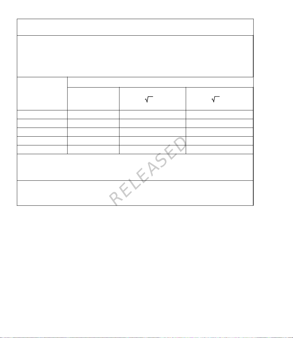
Guidance and Manufacturer's Declaration - Electromagnetic Immunity
The Guardian 2 Link is intended for use in the electromagnetic environment specified
below. The customer or user of the Guardian 2 Link should assure that it is used in
such an electromagnetic environment.
Immunity Test IEC 60601 Level Compliance Lev-elElectromagnetic Environ-
ment Guidance
Radiated RF
IEC 61000-4-3
3 V/m
80 MHz to
6 GHz
10 V/m
80 MHz to
6 GHz
d = 0.35
80 MHz to 800 MHz
d = 0.70
800 MHz to 6 GHz
Where P is the maximum output
power rating of the transmitter in
watts (W) according to the transmitter manufacturer and d is the
recommended separation distance in meters (m).
Field strengths from fixed RF
transmitters, as determined by
an electromagnetic site survey
should be less than the compliance level in each frequency
b
.
range
Interference may occur in the vi-
cinity of equipment marked with
the following symbol:
RELEASED
a
,
At 80 MHz and 800 MHz, the higher frequency range applies.
Note:
These guidelines may not apply in all situations. Electromagnetic propagation is affected by
Note:
absorption, and reflection from structures, objects and people.
a
Field strengths from fixed transmitters, such as base stations for radio (cellular/cordless) telephones
and land mobile radios, amateur radio, AM and FM radio broadcasts and TV broadcast cannot be predicted theoretically with accuracy. To assess the electromagnetic environment due to fixed RF transmitters, an electromagnetic site survey should be considered. If the measured field strength in the
location in which the Guardian 2 Link is used exceeds the applicable RF compliance level above, the
Guardian 2 Link should be observed to verify normal operation. If abnormal performance is observed,
additional measures may be necessary, such as re-orienting or relocating the Guardian 2 Link.
b
Over the frequency range 150 kHz to 80 MHz, field strengths should be less than 3 V/m.
-18-
MP6025871-12C1 / A
Recommended separation distances between the Guardia n 2 Link and common
household radio transmitters
Household RF Transmitter Frequency Recommended Sepa-
Telephones
Cordless Household 2.4 GHz 0.3 12
Cordless Household 5.8 GHz 0.3 12
TDMA-50 Hz (cell phone) 1. 9 GHz 0.3 12
TDMA-50 Hz (cell phone) 800 MHz 0.3 12
PCS (cell phone) 1.9 MHz 0.3 12
DCS (cell phone) 1.8 MHz 0.3 12
GSM (cell phone) 900 MHz 0.3 12
GSM (cell phone) 850 MHz 0.3 12
CDMA (cell phone) 800 MHz 0.3 12
Analog (cell phone) 824 MHz 0.3 12
CDMA (cell phone) 1.9 MHz 0.3 12
WiFi Networks
802.11b; 11Mbps maximum 2.4 GHz 1 39.5
802.11g; 54 Mbps maximum 2.4 GHz 1 39.5
802.11n; 11Mbps maximum 2.4 GHz 1 39.5
Bluetooth 500 kb/s 2.4 GHz 0.1 3.93
ZigBee 250 kb/s 2.4 GHz 0.1 3.93
RELEASED
ration Distance (meter)
Recommended Separation Distance (i nch)
English
-19-
P
P
MP6025871-12C1 / A
Recommended separation distances between por table and mobile RF
communications equipment and the Guardian 2 Link
The Guardian 2 Link is intended for use in an electromagnetic environment in which
radiated RF disturbances are controlled. The customer or the Guardian 2 Link users
can help prevent electromagnetic interference by maintaining a minimum distance between portable and mobile RF communications equipment and the Guardian 2 Link as
recommended below, according to the maximum output power of the communications
equipment.
Rated maximum
output power of
transmitter (W)
0.01 Not applicable 0.035 0.07
0.1 Not applicable 0.11 0.11
1 Not applicable 0. 35 0.7
10 Not applicable 1.1 2.2
100 Not applicable 3.5 7
For transmitters rated at a maximum output power not listed above, the recommended separation distance d in meters (m) can be estimated using the equation applicable to the frequency of the transmitter, where p is the maximum output power rating of the transmitter in watts (W) according to the
transmitter manufacturer.
At 80 MHz and 800 MHz, the separation distance for the higher frequency range applies.
Note:
These guidelines may not apply in all situations. Electromagnetic propagation is affected by
Note:
absorption and reflection from structures, objects, and people.
Separation distance according to the frequency of transmitter (m)
150 kHz to 80
MHz
Not applicable
80MHz to 800MHz
d = 0.35
800MHz to 6.0GHz
d = 0.70
RELEASED
-20-
MP6025871-12C1 / A
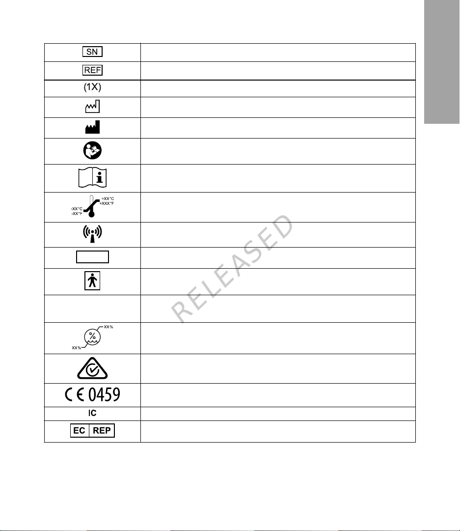
Icon Table
English
Serial number
Catalogue or model number
One per container/package
Date of manufacture
Manufacturer
Follow instructions for use (appears blue on label)
Consult instructions for use
Storage temperature range
Radio communication
CONF
IP48
Configuration or unique version identifier
Degree of protection against electric shock: Type BF applied part
Transmitter: Protected against the effects of continuous immersion in water
(2.4 meters (8 feet) immersion for 30 minutes).
RELEASED
Storage humidity range
RF device distributed in Australia
Marking of Conformity: This symbol means the device fully complies with
MDD 93/42/EEC (NB 0459).
RF device distributed in Canada
Authorized representative in the European community
©2015 Medtronic MiniMed, Inc. All rights reserved.
™
MiniMed
, Enlite™, and Guardian™ are trademarks of Medtronic MiniMed, Inc.
®
Detachol
is a registered trademark of Ferndale Laboratories Inc.
-21-

MP6025871-12C1 / A
RELEASED
-22-

MP6025871-12C1 / A
Le transmetteur Guardian™ 2 Link est un compo sa nt du sy stème de mes ur e du
glucose en continu pour la pompe à insuline MiniMed
les données provenant d'un capteur de glucose Enlite™. Le transmetteur les
transmet ensuite à la pompe à insu lin e vi a u ne co nnex io n sa ns fi l.
™
640G. Le transmetteur reço it
Composants du kit de transmetteur Guardian 2 Link
Un kit complet de transmetteur Guardian 2 Link comprend les éléments suivants :
• Transmetteur Guardian 2 Link (MMT-7731)
•
Testeur étanche (MMT-7726)
Chargeur (MMT-7715)
•
•
Serteur One-Press (MMT-7512)
Indications
Le transmetteur est destiné à un usage pour un seul patient, comme composant de
certains systèmes de mesure du glucose en continu de Med tronic et des systèmes
intégrés capteur/pompe de MiniMed.
Contre-indications
N'exposez pas un transmetteur à un équipement IRM, des appareils de diathermie
ou d'autres appareils pouv ant gén ér er des ch amp s mag néti que s de forte int ens ité .
En cas d'exposition involo nta ir e du trans met t eur à un cham p magné tiq ue de for te
intensité, arrêtez-en l'utilisation et contactez l'assistance 24 h/24 ou un représentant
local.
RELEASED
Avertissements
Le produit comporte des pièces de petite taille qui peuvent présenter un risque
d'étouffement pour les enfants en bas âge.
Si le testeur entre en contact avec du sang, le testeur doit être jeté. Éliminez le
testeur conformément à la réglementation locale applicable à l'élimination des
déchets médicaux.
Français
-23-

MP6025871-12C1 / A
L'insertion du capteur est susceptible de produire des saignements. Avant la connexion
du transmetteur au capteur, as sur ez- vou s d e l'abs enc e de saig nem ent au niv ea u du site
d'insertion. En cas de saignement, appliquez une pression constante avec une gaze
stérile ou un tissu propre sur le site d'insertion jusqu'à l'arrêt du saignement. Lorsque le
saignement s'arrête, con nec tez le tran sm ette ur au capt eur.
Contactez l'aide en ligne 24 h/24 ou un représentant local en cas de réactions
indésirables liées au transmetteur ou au capteur.
Champs magnétiques
N'exposez pas un transmetteur à un équipement IRM, des appareils de diathermie ou
d'autres appareils pouvant générer des champs magnétiques de forte intensité. En cas
d’exposition involontai re du transmetteur à un champ magnétique de forte intensité,
arrêtez-en l’utilisation et contactez l'aide en ligne 24 h/24 ou un représentant local.
Radiographie, IRM, diathermie et tomodensitométrie
Avant une radiographie, un traitement par diathermie, un tomodensitogramme, une IRM
ou un autre examen utilisant de s rad iations, retirez le capte ur et le transmetteur avant
d'entrer dans une pièce con tena nt ces appa re ils .
Vous trouverez sur votre carte d'urgence des informations importantes sur les systèmes
de sécurité des aéroports et sur l'utilisation de votre transmetteur dans les avions. En cas
de déplacements, veil lez à toujours porter sur vous la carte d'urg enc e four ni e av ec
l'appareil.
Précautions
Reportez-vous systématiquement au manuel d'utilisation du capteur Enlite pour
l'ensemble des préca utions, avertissement s et ins t ruc t ion s re l atif s au ca pteur.
Utilisez systématiqu eme nt le teste ur lors que vou s nettoyez le transmetteur. N'utilise z
aucun autre testeur avec le transmetteur.
Ne tournez pas le testeur ou le capteur quand celui-ci est connecté au transmetteur sous
peine d'endommager le transmetteur.
Ne laissez pas de l'eau ou tout autre liquide entrer en contact avec le testeur lorsque
celui-ci n'est pas connecté au tra ns metteur. Un testeur mouillé peut endomm age r le
transmetteur.
Évitez que le transmetteur entre en contact avec du liquide lorsque celui-ci n'est pas
connecté à un capteur ou au testeur.
Ne nettoyez pas les joints toriques du testeur, sous peine de les endommager.
RELEASED
-24-
 Loading...