

Page 1

FlowMet™
Peripheral Blood Flow Monitoring System
Operator's Manual
Caution: Federal law (USA) restricts this device to sale by or on the order of a physician.
Page 2

Medtronic, Medtronic with rising man logo, and Medtronic logo are trademarks of Medtronic. Third-party trademarks (“TM*”) belong to their respective owners. The following list includes trademarks or registered trademarks of a Medtronic entity in the United States
and/or in other countries.
FlowMet™
Page 3

Symbol definitions
Manufacturer
Serial number
Catalog number
Batch code
Caution: Consult accompanying documents
Consult instructions for use at this website
Keep dry
Fragile, handle with care
IPX0 - no claim of protection from water ingress
Type BF applied part
Prescription only
Nonsterile
Do not reuse
MR Unsafe
Not made with natural rubber latex
Does not contain PVC
Class 1 laser product
Quantity
Date of manufacture
Do not discard
3
Page 4

Contents
1 Device description . . . . . . . . . . . . . . . . . . . . . . . . . . . . . . . . . . . . . . . . . . . . . . . . . . . . . . . . . . . . . . . . . . . . . . . . . . . . . . . . . . . . . . . . . . . . . . . . . . . . . . . . . . . . . . . . . . . . . . . . . . . . . . . 5
1.1 Purpose of the monitoring system . . . . . . . . . . . . . . . . . . . . . . . . . . . . . . . . . . . . . . . . . . . . . . . . . . . . . . . . . . . . . . . . . . . . . . . . . . . . . . . . . . . . . . . . . . . . . . . . . . . . . . . . . . . . . . . . . . . . . . . . 5
1.2 Principle of operation . . . . . . . . . . . . . . . . . . . . . . . . . . . . . . . . . . . . . . . . . . . . . . . . . . . . . . . . . . . . . . . . . . . . . . . . . . . . . . . . . . . . . . . . . . . . . . . . . . . . . . . . . . . . . . . . . . . . . . . . . . . . . . . . . . . 5
1.3 Indications for use . . . . . . . . . . . . . . . . . . . . . . . . . . . . . . . . . . . . . . . . . . . . . . . . . . . . . . . . . . . . . . . . . . . . . . . . . . . . . . . . . . . . . . . . . . . . . . . . . . . . . . . . . . . . . . . . . . . . . . . . . . . . . . . . . . . . . 5
1.4 Intended patient population . . . . . . . . . . . . . . . . . . . . . . . . . . . . . . . . . . . . . . . . . . . . . . . . . . . . . . . . . . . . . . . . . . . . . . . . . . . . . . . . . . . . . . . . . . . . . . . . . . . . . . . . . . . . . . . . . . . . . . . . . . . . . . 5
1.5 Use environment . . . . . . . . . . . . . . . . . . . . . . . . . . . . . . . . . . . . . . . . . . . . . . . . . . . . . . . . . . . . . . . . . . . . . . . . . . . . . . . . . . . . . . . . . . . . . . . . . . . . . . . . . . . . . . . . . . . . . . . . . . . . . . . . . . . . . . 5
1.6 Contraindications . . . . . . . . . . . . . . . . . . . . . . . . . . . . . . . . . . . . . . . . . . . . . . . . . . . . . . . . . . . . . . . . . . . . . . . . . . . . . . . . . . . . . . . . . . . . . . . . . . . . . . . . . . . . . . . . . . . . . . . . . . . . . . . . . . . . . . 5
2 Warnings . . . . . . . . . . . . . . . . . . . . . . . . . . . . . . . . . . . . . . . . . . . . . . . . . . . . . . . . . . . . . . . . . . . . . . . . . . . . . . . . . . . . . . . . . . . . . . . . . . . . . . . . . . . . . . . . . . . . . . . . . . . . . . . . . . . . . . . 5
2.1 Environmental . . . . . . . . . . . . . . . . . . . . . . . . . . . . . . . . . . . . . . . . . . . . . . . . . . . . . . . . . . . . . . . . . . . . . . . . . . . . . . . . . . . . . . . . . . . . . . . . . . . . . . . . . . . . . . . . . . . . . . . . . . . . . . . . . . . . . . . . 5
2.2 Operational or usage . . . . . . . . . . . . . . . . . . . . . . . . . . . . . . . . . . . . . . . . . . . . . . . . . . . . . . . . . . . . . . . . . . . . . . . . . . . . . . . . . . . . . . . . . . . . . . . . . . . . . . . . . . . . . . . . . . . . . . . . . . . . . . . . . . . 6
2.3 Equipment . . . . . . . . . . . . . . . . . . . . . . . . . . . . . . . . . . . . . . . . . . . . . . . . . . . . . . . . . . . . . . . . . . . . . . . . . . . . . . . . . . . . . . . . . . . . . . . . . . . . . . . . . . . . . . . . . . . . . . . . . . . . . . . . . . . . . . . . . . . 6
3 Precautions . . . . . . . . . . . . . . . . . . . . . . . . . . . . . . . . . . . . . . . . . . . . . . . . . . . . . . . . . . . . . . . . . . . . . . . . . . . . . . . . . . . . . . . . . . . . . . . . . . . . . . . . . . . . . . . . . . . . . . . . . . . . . . . . . . . . . 6
3.1 Environmental . . . . . . . . . . . . . . . . . . . . . . . . . . . . . . . . . . . . . . . . . . . . . . . . . . . . . . . . . . . . . . . . . . . . . . . . . . . . . . . . . . . . . . . . . . . . . . . . . . . . . . . . . . . . . . . . . . . . . . . . . . . . . . . . . . . . . . . . 6
3.2 Operational or usage . . . . . . . . . . . . . . . . . . . . . . . . . . . . . . . . . . . . . . . . . . . . . . . . . . . . . . . . . . . . . . . . . . . . . . . . . . . . . . . . . . . . . . . . . . . . . . . . . . . . . . . . . . . . . . . . . . . . . . . . . . . . . . . . . . . 6
3.3 Equipment . . . . . . . . . . . . . . . . . . . . . . . . . . . . . . . . . . . . . . . . . . . . . . . . . . . . . . . . . . . . . . . . . . . . . . . . . . . . . . . . . . . . . . . . . . . . . . . . . . . . . . . . . . . . . . . . . . . . . . . . . . . . . . . . . . . . . . . . . . . 7
4 Potential adverse events . . . . . . . . . . . . . . . . . . . . . . . . . . . . . . . . . . . . . . . . . . . . . . . . . . . . . . . . . . . . . . . . . . . . . . . . . . . . . . . . . . . . . . . . . . . . . . . . . . . . . . . . . . . . . . . . . . . . . . . . . . 7
5 Cybersecurity . . . . . . . . . . . . . . . . . . . . . . . . . . . . . . . . . . . . . . . . . . . . . . . . . . . . . . . . . . . . . . . . . . . . . . . . . . . . . . . . . . . . . . . . . . . . . . . . . . . . . . . . . . . . . . . . . . . . . . . . . . . . . . . . . . . 7
5.1 Wireless features . . . . . . . . . . . . . . . . . . . . . . . . . . . . . . . . . . . . . . . . . . . . . . . . . . . . . . . . . . . . . . . . . . . . . . . . . . . . . . . . . . . . . . . . . . . . . . . . . . . . . . . . . . . . . . . . . . . . . . . . . . . . . . . . . . . . . . 7
5.2 Use of USB port on tablet . . . . . . . . . . . . . . . . . . . . . . . . . . . . . . . . . . . . . . . . . . . . . . . . . . . . . . . . . . . . . . . . . . . . . . . . . . . . . . . . . . . . . . . . . . . . . . . . . . . . . . . . . . . . . . . . . . . . . . . . . . . . . . . 7
5.3 Use of Windows OS passwords . . . . . . . . . . . . . . . . . . . . . . . . . . . . . . . . . . . . . . . . . . . . . . . . . . . . . . . . . . . . . . . . . . . . . . . . . . . . . . . . . . . . . . . . . . . . . . . . . . . . . . . . . . . . . . . . . . . . . . . . . . 7
5.4 Use of other software on the tablet . . . . . . . . . . . . . . . . . . . . . . . . . . . . . . . . . . . . . . . . . . . . . . . . . . . . . . . . . . . . . . . . . . . . . . . . . . . . . . . . . . . . . . . . . . . . . . . . . . . . . . . . . . . . . . . . . . . . . . . . 7
5.5 Software updates . . . . . . . . . . . . . . . . . . . . . . . . . . . . . . . . . . . . . . . . . . . . . . . . . . . . . . . . . . . . . . . . . . . . . . . . . . . . . . . . . . . . . . . . . . . . . . . . . . . . . . . . . . . . . . . . . . . . . . . . . . . . . . . . . . . . . . 7
5.6 Identification of cybersecurity risks . . . . . . . . . . . . . . . . . . . . . . . . . . . . . . . . . . . . . . . . . . . . . . . . . . . . . . . . . . . . . . . . . . . . . . . . . . . . . . . . . . . . . . . . . . . . . . . . . . . . . . . . . . . . . . . . . . . . . . . . 7
6 Monitoring system components and specifications . . . . . . . . . . . . . . . . . . . . . . . . . . . . . . . . . . . . . . . . . . . . . . . . . . . . . . . . . . . . . . . . . . . . . . . . . . . . . . . . . . . . . . . . . . . . . . . . . . . 7
6.1 Monitoring system components . . . . . . . . . . . . . . . . . . . . . . . . . . . . . . . . . . . . . . . . . . . . . . . . . . . . . . . . . . . . . . . . . . . . . . . . . . . . . . . . . . . . . . . . . . . . . . . . . . . . . . . . . . . . . . . . . . . . . . . . . . 7
6.2 Specifications . . . . . . . . . . . . . . . . . . . . . . . . . . . . . . . . . . . . . . . . . . . . . . . . . . . . . . . . . . . . . . . . . . . . . . . . . . . . . . . . . . . . . . . . . . . . . . . . . . . . . . . . . . . . . . . . . . . . . . . . . . . . . . . . . . . . . . . . . 8
7 Environmental conditions that affect use . . . . . . . . . . . . . . . . . . . . . . . . . . . . . . . . . . . . . . . . . . . . . . . . . . . . . . . . . . . . . . . . . . . . . . . . . . . . . . . . . . . . . . . . . . . . . . . . . . . . . . . . . . . . 9
7.1 Temperature . . . . . . . . . . . . . . . . . . . . . . . . . . . . . . . . . . . . . . . . . . . . . . . . . . . . . . . . . . . . . . . . . . . . . . . . . . . . . . . . . . . . . . . . . . . . . . . . . . . . . . . . . . . . . . . . . . . . . . . . . . . . . . . . . . . . . . . . . . 9
7.2 Lighting . . . . . . . . . . . . . . . . . . . . . . . . . . . . . . . . . . . . . . . . . . . . . . . . . . . . . . . . . . . . . . . . . . . . . . . . . . . . . . . . . . . . . . . . . . . . . . . . . . . . . . . . . . . . . . . . . . . . . . . . . . . . . . . . . . . . . . . . . . . . . . 9
8 Setup and shut down instructions . . . . . . . . . . . . . . . . . . . . . . . . . . . . . . . . . . . . . . . . . . . . . . . . . . . . . . . . . . . . . . . . . . . . . . . . . . . . . . . . . . . . . . . . . . . . . . . . . . . . . . . . . . . . . . . . . . 9
8.1 Setup instructions . . . . . . . . . . . . . . . . . . . . . . . . . . . . . . . . . . . . . . . . . . . . . . . . . . . . . . . . . . . . . . . . . . . . . . . . . . . . . . . . . . . . . . . . . . . . . . . . . . . . . . . . . . . . . . . . . . . . . . . . . . . . . . . . . . . . . 9
8.2 Exit instructions . . . . . . . . . . . . . . . . . . . . . . . . . . . . . . . . . . . . . . . . . . . . . . . . . . . . . . . . . . . . . . . . . . . . . . . . . . . . . . . . . . . . . . . . . . . . . . . . . . . . . . . . . . . . . . . . . . . . . . . . . . . . . . . . . . . . . . . 9
8.3 Shut down instructions . . . . . . . . . . . . . . . . . . . . . . . . . . . . . . . . . . . . . . . . . . . . . . . . . . . . . . . . . . . . . . . . . . . . . . . . . . . . . . . . . . . . . . . . . . . . . . . . . . . . . . . . . . . . . . . . . . . . . . . . . . . . . . . . . 9
9 Pre-use checklist . . . . . . . . . . . . . . . . . . . . . . . . . . . . . . . . . . . . . . . . . . . . . . . . . . . . . . . . . . . . . . . . . . . . . . . . . . . . . . . . . . . . . . . . . . . . . . . . . . . . . . . . . . . . . . . . . . . . . . . . . . . . . . . . 9
10 Operating instructions . . . . . . . . . . . . . . . . . . . . . . . . . . . . . . . . . . . . . . . . . . . . . . . . . . . . . . . . . . . . . . . . . . . . . . . . . . . . . . . . . . . . . . . . . . . . . . . . . . . . . . . . . . . . . . . . . . . . . . . . . 10
10.1 Attaching the sensor . . . . . . . . . . . . . . . . . . . . . . . . . . . . . . . . . . . . . . . . . . . . . . . . . . . . . . . . . . . . . . . . . . . . . . . . . . . . . . . . . . . . . . . . . . . . . . . . . . . . . . . . . . . . . . . . . . . . . . . . . . . . . . . . . 10
10.2 Removing the sensor . . . . . . . . . . . . . . . . . . . . . . . . . . . . . . . . . . . . . . . . . . . . . . . . . . . . . . . . . . . . . . . . . . . . . . . . . . . . . . . . . . . . . . . . . . . . . . . . . . . . . . . . . . . . . . . . . . . . . . . . . . . . . . . . 11
10.3 FlowMet software . . . . . . . . . . . . . . . . . . . . . . . . . . . . . . . . . . . . . . . . . . . . . . . . . . . . . . . . . . . . . . . . . . . . . . . . . . . . . . . . . . . . . . . . . . . . . . . . . . . . . . . . . . . . . . . . . . . . . . . . . . . . . . . . . . . . 11
10.4 Advanced options . . . . . . . . . . . . . . . . . . . . . . . . . . . . . . . . . . . . . . . . . . . . . . . . . . . . . . . . . . . . . . . . . . . . . . . . . . . . . . . . . . . . . . . . . . . . . . . . . . . . . . . . . . . . . . . . . . . . . . . . . . . . . . . . . . . 16
11 Cleaning . . . . . . . . . . . . . . . . . . . . . . . . . . . . . . . . . . . . . . . . . . . . . . . . . . . . . . . . . . . . . . . . . . . . . . . . . . . . . . . . . . . . . . . . . . . . . . . . . . . . . . . . . . . . . . . . . . . . . . . . . . . . . . . . . . . . . 16
11.1 Instructions for cleaning reusable cable . . . . . . . . . . . . . . . . . . . . . . . . . . . . . . . . . . . . . . . . . . . . . . . . . . . . . . . . . . . . . . . . . . . . . . . . . . . . . . . . . . . . . . . . . . . . . . . . . . . . . . . . . . . . . . . . . . 16
11.2 Instructions for cleaning tablet, typepad, and power supply . . . . . . . . . . . . . . . . . . . . . . . . . . . . . . . . . . . . . . . . . . . . . . . . . . . . . . . . . . . . . . . . . . . . . . . . . . . . . . . . . . . . . . . . . . . . . . . . . . 16
12 Maintenance . . . . . . . . . . . . . . . . . . . . . . . . . . . . . . . . . . . . . . . . . . . . . . . . . . . . . . . . . . . . . . . . . . . . . . . . . . . . . . . . . . . . . . . . . . . . . . . . . . . . . . . . . . . . . . . . . . . . . . . . . . . . . . . . . . 16
13 Storage, transport and disposal . . . . . . . . . . . . . . . . . . . . . . . . . . . . . . . . . . . . . . . . . . . . . . . . . . . . . . . . . . . . . . . . . . . . . . . . . . . . . . . . . . . . . . . . . . . . . . . . . . . . . . . . . . . . . . . . . 16
13.1 Storage and transport . . . . . . . . . . . . . . . . . . . . . . . . . . . . . . . . . . . . . . . . . . . . . . . . . . . . . . . . . . . . . . . . . . . . . . . . . . . . . . . . . . . . . . . . . . . . . . . . . . . . . . . . . . . . . . . . . . . . . . . . . . . . . . . . 16
13.2 Disposal of product . . . . . . . . . . . . . . . . . . . . . . . . . . . . . . . . . . . . . . . . . . . . . . . . . . . . . . . . . . . . . . . . . . . . . . . . . . . . . . . . . . . . . . . . . . . . . . . . . . . . . . . . . . . . . . . . . . . . . . . . . . . . . . . . . . 16
14 Troubleshooting . . . . . . . . . . . . . . . . . . . . . . . . . . . . . . . . . . . . . . . . . . . . . . . . . . . . . . . . . . . . . . . . . . . . . . . . . . . . . . . . . . . . . . . . . . . . . . . . . . . . . . . . . . . . . . . . . . . . . . . . . . . . . . . 16
14.1 Software . . . . . . . . . . . . . . . . . . . . . . . . . . . . . . . . . . . . . . . . . . . . . . . . . . . . . . . . . . . . . . . . . . . . . . . . . . . . . . . . . . . . . . . . . . . . . . . . . . . . . . . . . . . . . . . . . . . . . . . . . . . . . . . . . . . . . . . . . . . 16
14.2 Monitoring system warning prompts . . . . . . . . . . . . . . . . . . . . . . . . . . . . . . . . . . . . . . . . . . . . . . . . . . . . . . . . . . . . . . . . . . . . . . . . . . . . . . . . . . . . . . . . . . . . . . . . . . . . . . . . . . . . . . . . . . . . 16
14.3 Troubleshooting table . . . . . . . . . . . . . . . . . . . . . . . . . . . . . . . . . . . . . . . . . . . . . . . . . . . . . . . . . . . . . . . . . . . . . . . . . . . . . . . . . . . . . . . . . . . . . . . . . . . . . . . . . . . . . . . . . . . . . . . . . . . . . . . . 16
15 Guidance and manufacturer’s declaration . . . . . . . . . . . . . . . . . . . . . . . . . . . . . . . . . . . . . . . . . . . . . . . . . . . . . . . . . . . . . . . . . . . . . . . . . . . . . . . . . . . . . . . . . . . . . . . . . . . . . . . . . 17
15.1 Electromagnetic compatibility (EMC) declaration tables . . . . . . . . . . . . . . . . . . . . . . . . . . . . . . . . . . . . . . . . . . . . . . . . . . . . . . . . . . . . . . . . . . . . . . . . . . . . . . . . . . . . . . . . . . . . . . . . . . . . 17
15.2 IEC 60601-1 . . . . . . . . . . . . . . . . . . . . . . . . . . . . . . . . . . . . . . . . . . . . . . . . . . . . . . . . . . . . . . . . . . . . . . . . . . . . . . . . . . . . . . . . . . . . . . . . . . . . . . . . . . . . . . . . . . . . . . . . . . . . . . . . . . . . . . . . 18
15.3 IEC 60825-1 . . . . . . . . . . . . . . . . . . . . . . . . . . . . . . . . . . . . . . . . . . . . . . . . . . . . . . . . . . . . . . . . . . . . . . . . . . . . . . . . . . . . . . . . . . . . . . . . . . . . . . . . . . . . . . . . . . . . . . . . . . . . . . . . . . . . . . . . 18
16 Warranty . . . . . . . . . . . . . . . . . . . . . . . . . . . . . . . . . . . . . . . . . . . . . . . . . . . . . . . . . . . . . . . . . . . . . . . . . . . . . . . . . . . . . . . . . . . . . . . . . . . . . . . . . . . . . . . . . . . . . . . . . . . . . . . . . . . . . 19
4
Page 5

1 Device description
The FlowMet peripheral blood flow monitoring system (Figure 1) measures real-time blood flow rate in the extremities. The monitoring system is comprised of a Microsoft Surface Pro Tablet
(tablet), power supply, FlowMet reusable cable (reusable cable), and FlowMet™ digit flow sensor (sensor). The tablet, power supply and reusable cable are intended for multiple uses and
should not be discarded. The sensor, with its adhesive components, is for single patient use only.
Figure 1. FlowMet peripheral blood flow monitoring system
1.1 Purpose of the monitoring system
The monitoring system is capable of measuring microvascular blood flow rate in fingers or toes. Active monitoring system components include an infrared laser diode and image sensor.
1.2 Principle of operation
The monitoring system directly measures blood flow rate within the full thickness of a digit via dynamic light scattering. Erythrocytes within the blood vessels of the digit scatter incident photons.
The monitoring system projects light through one side of the digit and uses a light sensor on the opposing side to measure how the pattern of light scattered by erythrocytes changes over time.
The speed with which the resulting scattered light pattern changes is proportional to blood flow rate in the interrogated digit.
1.3 Indications for use
The FlowMet is a non-invasive probe that is affixed to the fingers or toes and intended to quantify tissue blood flow rate.
1.4 Intended patient population
The intended patient population for the monitoring system is individuals with vascular disease, such as those with peripheral artery disease.
1.5 Use environment
The monitoring system is intended for use in clinical environments. This most commonly includes operating suites, but may also include other clinical use environments.
1.6 Contraindications
Do not use on patients that present or have known allergies to adhesive tape. The sensor is comprised of both synthetic rubber and silicone adhesives.
Do not use the device in an MR (magnetic resonance) environment, explosive atmosphere, or pressurized chamber.
This device is not defibrillation proof per IEC 60601-1 clause 8.5.5.
2 Warnings
2.1 Environmental
• Explosion hazard. Do not use in flammable environments such as a hyperbaric chamber, oxygen rich environment, or near flammable anesthetics.
• Do not use during magnetic resonance imaging (MRI) scanning.
• Do not use during diathermy or electrocautery.
• Be careful of unexpected signal variation due to radio frequency (RF) emitters (e.g. RFID). If there is suspicion of unexpected signal variation, see Chapter 14, Troubleshooting,
page 16.
• Do not use the monitoring system in overly damp environments (relative humidity 20% to 80% noncondensing).
• Do not use the monitoring system outside of its intended temperature operating range (5°C [41°F] to 23°C [73°F]). Doing so could result in device non-operation or excessively high surface
temperatures, which can cause burns.
5
Page 6

• Do not expose the monitoring system to any liquids besides wipes used for cleaning. Inappropriate exposure of the monitoring system to liquids may result in electrocution or burns.
• Portable RF communications equipment such as antennas, wireless microphones, cordless telephones, Wi-Fi transmitters, Bluetooth radio devices, etc. may affect the functionality of the
monitoring system and should not be placed or operated within 24 in (0.6 m) of the system and its components (tablet, cables, sensor, power supply, and accompanying cables).
• As a light-based system, external lighting can sometimes influence monitoring system measurements. Generally, too much light exposure will trigger a warning from the system; however,
it is possible for external lighting to adversely affect measurements without triggering a system warning. As such, the user should be careful of the lighting within the surroundings. Some
possible sources of light interference are direct sunlight, fluorescent lights, surgical lamps, infrared heating lamps, and bilirubin lamps. These situations can be remedied by shielding the
sensor with an opaque material if necessary.
• Do not autoclave or submerge the equipment in any cleaning solution.
2.2 Operational or usage
• Do not stack any components or accessories of the monitoring system on or close to other equipment that may pose electromagnetic (EM) disturbances or vice versa. If this situation is
unavoidable, the monitoring system itself as well as the equipment it is in close proximity with should be tested prior to use to assure both the monitoring system and the other equipment
are functioning as intended.
• Do not start the monitoring system unless the sensor is applied to a digit (finger or toe). Stop the monitoring system before removing the sensor from the digit. Failure to use the monitoring
system as described in this manual could result in exposure to laser radiation, which is potentially harmful to the eyes. Never stare into the laser beam.
• Carefully route cabling to reduce the possibility of entanglement.
• Cables and accessories of the monitoring system may negatively affect the EMC performance of other devices or equipment and vice versa. Caution should be taken to ensure proper
isolated equipment placement.
• Always attach the sensor as described in this manual. Improper application of the sensor to the digits or application of the sensor to locations other than the digits may damage tissue at
the application site.
• Ensure the sensor is not too tight, especially in the case of patients with poor perfusion. A sensor that is too tight or becomes too tight as a result of edema may lead to inaccurate readings
or tissue damage. Tissue damage may result by way of ischemia followed by subsequent pressure necrosis or skin erosion. The sensor site should be monitored frequently, every 30 min,
for signs of ischemia or any other form of tissue maladies.
• Do not use additional adhesive material or medical tape to affix the sensor to the patient due to potential allergic side effects as well as over-tightening of the sensor, which could lead to
tissue damage by way of ischemia followed by subsequent pressure necrosis or skin erosion.
• The sensor is not a sterile device. It should not be placed on digits with open wounds or compromised tissue.
• The sensor is comprised of adhesive material or medical tape. In the opinion of the medical professional, the sensor should not be placed on digits with compromised tissue where the
sensor removal could cause tissue damage.
• If the sensor begins to feel uncomfortably warm, stop the software and remove the device.
• The sensor is a single patient use disposable device and should not be cleaned or reused. The sensor may be repositioned on the same patient, during a single procedure, provided the
sensor provides adequate adhesion to the digit.
• Always clean the reusable cable between every use with isopropyl alcohol, germicidal wipe, 10% bleach solution, or comparable disinfecting solution.
• During removal of the sensor, be careful of causing damage to the underlying and surrounding tissue where the sensor is attached.
• Before removing the sensor from the digit, examine the digit and its surrounding tissue for any signs of damage or injury which may require special attention.
• The monitoring system is intended for use within a hospital setting and only by trained personnel.
• Even though the reusable cable is cleaned prior to storage, it should be cleaned once again just before use on the patient.
• The tablet is portable but it is intended to be stationary during operation of the monitoring system.
2.3 Equipment
• Do not attempt to remove the attached case on the tablet.
• The components and accessories of the monitoring system should not be exchanged or replaced with parts not included with the monitoring system. Do not substitute the provided power
supply with an aftermarket power supply. Use of components or accessories not included with the monitoring system could result in inaccurate measurements or device non-operation.
• Never use the monitoring system if any of the components exhibit visible defects, discoloration, or signs of damage.
• Do not adjust, repair, open, disassemble, or modify this unit. Injury or equipment damage could occur. If the monitoring system is malfunctioning or appears to be visibly damaged, contact
Medtronic.
• Do not attempt to replace any batteries or fuel cells within the monitoring system. If there is suspected damage to the internal battery (lithium-ion) or fuel cells, Medtronic will replace the
tablet per the conditions stated in the warranty.
• Ensure the tablet and its power supply are at least 6.6 ft (2.0 m) away from the patient.
• The power supply isolates the display and sensor from the supply mains. Ensure there is adequate space to disconnect the power supply if necessary.
• The monitoring system should only be used by trained personnel that have read the manual in its entirety.
• The monitoring system has been designed for use by trained personnel on a patient. The monitoring system has not been designed for taking self-measurements. There are no functions
that the patient can safely use during proper operation of the monitoring system.
• Not following the proper cleaning instructions stated within this manual could lead to permanent damage of the monitoring system or injury to the user or the patient.
• Do not clean or service any parts of the monitoring system while the monitoring system is in use.
• Ensure all devices and components are off and unplugged prior to cleaning.
• While there are no maintenance requirements for the monitoring system, do not clean or service any parts of the monitoring system while the device is in use.
• The provided cables (reusable cable, power supply) were included in EMC testing to demonstrate compliance with regulatory requirements. Use of accessories other than those provided
by Medtronic may result in increased emissions or decreased immunity of the monitoring system and result in improper operation.
• The power supply shipped with the monitoring system is the only power supply certified for use with the monitoring system.
• Do not use the sensor, reusable cable, or any cable with exposed optical or electrical components.
• Do not use discolored or damaged sensors or reusable cables.
3 Precautions
3.1 Environmental
• High-intensity lights (including pulsating strobe lights and direct sunlight) may affect readings.
• Dispose of the device in accordance with applicable laws, regulations, and hospital procedures, including those regarding biohazards, microbial hazards, and infectious substances.
3.2 Operational or usage
• Inaccurate blood flow readings may be caused by:
– Nail polish
– Intravascular dyes
– Digits with unusually large or small size or deformation
– Significant patient motion
– Improper device placement
– Sensor applied too tight
• Accuracy may be affected if too much or too little light is getting to the detector. A corresponding warning prompt will flash on the screen when this is suspected.
6
Page 7

3.3 Equipment
• Do not plug any device into the tablet USB port other than the reusable cable, which has a USB connection.
• Users should set up a Microsoft Windows operating system password on the tablet. Establishing a unique password reduces the risk of compromised device functionality and loss of data
(medical or personal) availability or integrity.
• The tablet included with the monitoring system should only be used to run the FlowMet software. Use of other software or changes to system settings may result in the FlowMet software
exhibiting unpredictable or unstable behavior.
• The monitoring system is shipped with a tamper evident tie affixed to the black hard-shell case. If this tie appears damaged upon receipt of the monitoring system, contact Medtronic.
• Replacement parts or any other component substitutions should not be carried out without contacting Medtronic first.
• Suspected malfunction of any monitoring system components should be brought to the attention of Medtronic. Aside from the suggested remedies listed in Section 14.3, Troubleshooting
table, page 16, there is nothing else the user can do to safely and efficiently remedy the issue.
• Do not soak or immerse any components of the monitoring system in any liquid solution.
• Do not use undiluted bleach or any cleaning solution other than those recommended in Section 11.1, Instructions for cleaning reusable cable, page 16.
• Do not clean or sterilize by means of irradiation, steam, autoclave or ethylene oxide.
• Do not clean with harsh solvents such as acetone or petroleum-based solutions.
• Do not aggressively twist or pull on the sensor while cleaning.
4 Potential adverse events
The potential adverse events (or complications) that may occur or require intervention with the use of this device include, but are not limited to, the following conditions:
• Allergic reaction to adhesive tape
• Burns
• Electrocution
• Entanglement
• Eye damage
• Ischemia
• Pressure necrosis
• Skin erosion
5 Cybersecurity
5.1 Wireless features
Wireless features (Wi-Fi and Bluetooth) on the tablet included with the monitoring system have been disabled. These features should not be enabled by the user, as doing so places the tablet
at risk of introduction of malware and unanticipated software errors. Windows anti-virus and firewall protection are enabled on the tablet. These features reduce the risk of malware and should
not be disabled.
5.2 Use of USB port on tablet
Caution: Do not plug any device into the tablet USB port other than the reusable cable, which has a USB connection.
The reusable cable and sensor connects to the tablet using the tablet’s USB interface. The USB interface is not intended for any uses other than attaching the reusable cable and sensor to
the tablet. Plugging other devices into the USB port may result in introduction of malware and unanticipated software errors.
5.3 Use of Windows OS passwords
Caution: Users should set up a Microsoft Windows operating system password on the tablet. Establishing a unique password reduces the risk of compromised device functionality and loss
of data (medical or personal) availability or integrity.
To set up a Windows OS password, open control panel and select Accounts. Select the account you’d like to add a password for and choose Change your password.
5.4 Use of other software on the tablet
Caution: The tablet included with the monitoring system should only be used to run the FlowMet software. Use of other software or changes to system settings may result in the FlowMet
software exhibiting unpredictable or unstable behavior.
5.5 Software updates
Instructions pertaining to software updates will be provided by Medtronic at the time the software update is released. Questions regarding software updates may be directed to Medtronic.
5.6 Identification of cybersecurity risks
Caution: The monitoring system is shipped with a tamper evident tie affixed to the black hard-shell case. If this tie appears damaged upon receipt of the monitoring system, contact Medtronic.
If cybersecurity risks not described in this manual are identified by the user, contact Medtronic.
6 Monitoring system components and specifications
6.1 Monitoring system components
6.1.1 Reusable components
• Custom hard-shelled case
• FlowMet reusable cable, USB to sensor, 10 ft (3.0 m)
• Microsoft Surface Pro Tablet, Windows 10 OS
• Microsoft Surface typepad (part of the Microsoft Surface Pro Tablet)
• Microsoft Surface Pro power supply
• Pre-installed FlowMet software
6.1.2 Single patient use components (disposable)
• FlowMet sensor
Note: Possession or purchase of this device does not convey any express or implied license to use the device with unauthorized sensors or cables which would, alone, or in combination with
this device, fall within the scope of one or more of the patents relating to this device.
Note: Except for the sensor, all of the components within the monitoring system are reusable, none are disposable.
Note: The user must follow the instructions outlined for proper cleaning, except for the sensor. See Chapter 11, Cleaning, page 16 for cleaning instructions.
Note: None of the components and accessories within the monitoring system are sterile.
Caution: Replacement parts or any other component substitutions should not be carried out without contacting Medtronic first.
Caution: Suspected malfunction of any FlowMet components should be brought to the attention of Medtronic. Aside from the suggested remedies listed in Chapter 14, Troubleshooting,
page 16, there is nothing else the user can do to safely and efficiently remedy the issue.
7
Page 8

Warning: Do not attempt to replace any batteries or fuel cells within the monitoring system. If there is suspected damage to the internal battery (lithium-ion) or fuel cells, Medtronic will replace
the tablet per the conditions stated in the warranty.
Warning: Do not attempt to remove the attached case on the tablet.
6.2 Specifications
Specifications
Microsoft Surface Pro tablet Portable
Reusable cable Rigid housing material: Polycarbonate/ABS Blend (not intended to contact patient)
Sensor Body-worn, Applied part Type BF
Laser specifications Wavelength: 785 nm
Input rating 100 – 240 V ~, 50-60 Hz, 0.58 - 1.16 A
Mode of operation Continuous operation
Image sensor signal range 0 to 255 counts
Blood flow rate range 0 to 100
IP rating IPX0
Expected service life Reusable cable - 146 hours
Environmental and operating conditions
Temperature (operating) 41°F to 73.4°F (5°C to 23°C)
Relative humidity 20% to 80% noncondensing
Altitude (operating) 0 ft to 9,482 ft (0 m to 3,000 m); 101 kPa to 66 kPa
Storage and transport
Reusable components (custom hard-shelled case, reusable cable, tablet, power supply)
Temperature 32°F to 122°F (0°C to 50°C)
Altitude -1,000 ft to 9,482 ft (-304 m to 3,000 m); 66 kPa to 106 kPa
Relative humidity 20% to 80% noncondensing
Sensor
Temperature transport 32°F to 122°F (0°C to 50°C)
Temperature storage 73°F (23°C)
Altitude (storage and transport) -1,000 ft to 9,482 ft (-304 m to 3,000 m); 66 kPa to 106 kPa
Relative humidity transport 20% to 80% noncondensing
Relative humidity storage 50% noncondensing
Complies with FDA performance standards for laser products except for conformance with IEC 60825-1 Ed. 3 and IEC 60601-2- 22 Ed. 3.1, as described in Laser Notice No. 56, dated May
8, 2019.
6.2.1 Linearity
In vitro linearity of the monitoring system was validated over three trials by performing measurements on a finger analogue perfused with blood-simulating fluid. Flow rate in the analogue was
controlled using a calibrated syringe pump.
Expected volumetric flow (mL/min)
6.2.2 Variability
In vitro variability of the monitoring system was validated over six trials by performing measurements on a finger analogue perfused with blood-simulating fluid. Flow rate in the analogue was
controlled using a calibrated syringe pump. Coefficient of variation was computed while varying the artificial skin coloration of the finger analogue between trials.
Expected volumetric flow (mL/min)
2 14.6 2.67
4 27.0 0.00
6 39.4 1.03
8 51.3 0.59
10 63.4 0.63
12 74.8 0.40
14 86.5 0.69
16 98.8 0.30
18 110.9 0.18
20 123.8 0.49
2 15.9 1.37
4 28.8 1.52
6 41.0 1.58
8 52.8 1.70
10 64.2 2.00
12 75.6 2.31
14 86.8 2.87
16 97.3 2.78
Average monitoring system response (a.u.) Percent error relative projected linear response (%)
Average monitoring system response (a.u.) Coefficient of variation (%)
Rigid housing material: Polycarbonate/ABS blend
Adhesive tape:
• Single-coated, white polyethylene nonwoven with an acrylic adhesive
• Double-coated, white pearlized OPP (Oriented Polypropylene) film, with an acrylic adhesive on the metalized side and synthetic rubber adhesive on the pearlized side
• Polyethylene film with an acrylic adhesive
• Single-coated, Duolaminate PU film with a soft silicone adhesive
• Single-coated, white, soft, conformable, thick EVA foam with an acrylic adhesive
Output: Continuous wave
Maximum output: 0.5 mW
Class 1 per IEC 60825-1:2014
Tablet - 146 hours
Sensor - 24 hours
Ideal operating temperature: 68°F to 73.4°F (20°C to 23°C)
8
Page 9

Expected volumetric flow (mL/min) Average monitoring system response (a.u.) Coefficient of variation (%)
The upper and lower flow rate expected within the digits will depend on the specific biology of each patient, but the general physiological range of the monitoring system values is approximately
0-100.
18 108.2 3.34
20 118.9 4.49
7 Environmental conditions that affect use
Warning: Do not use during magnetic resonance imaging (MRI) scanning.
Warning: Do not use during diathermy or electrocautery.
Warning: Be careful of unexpected signal variation due to RF emitters (e.g. RFID). If there is suspicion of unexpected signal variation, see Chapter 14, Troubleshooting, page 16.
Warning: Portable RF communications equipment such as antennas, wireless microphones, cordless telephones, Wi-Fi transmitters, Bluetooth radio devices, etc. may affect the functionality
of the monitoring system and should not be placed or operated within 24 in (0.6 m) of the system and its components (tablet, cables, sensor, power supply, and accompanying cables).
7.1 Temperature
As a dynamic parameter, blood flow can vary with internal patient temperature and external ambient temperature. To improve the quality and repeatability of the measurements, it is best to
maintain a consistent temperature range when taking measurements (room temperature 73.4°F, 23°C); however, the monitoring system will function properly within the environmental
conditions. See Section 6.2, Specifications, page 8 for environmental and operating conditions.
7.2 Lighting
Warning: As a light-based system, external lighting can sometimes influence monitoring system measurements. Generally, too much light exposure will trigger a warning from the system;
however, it is possible for external lighting to adversely affect measurements without triggering a system warning. As such, the user should be careful of the lighting within the surroundings.
Some possible sources of light interference are direct sunlight, fluorescent lights, surgical lamps, infrared heating lamps, and bilirubin lamps. These situations can be remedied by shielding
the sensor with an opaque material if necessary.
8 Setup and shut down instructions
8.1 Setup instructions
Note: Refer to the FlowMet Peripheral Blood Flow Monitoring System Quick Start Guide for getting started with the monitoring system. The quick start guide is provided with the monitoring
system.
1. Unlatch the two clasps on the hard-shelled case to remove the monitoring system.
2. Remove the tablet from the case to reveal the remaining components of the monitoring system.
3. Remove the tablet power supply and reusable cable.
4. When setting up the tablet and its power supply, ensure it is at least 6.6 ft (2.0 m) away from the patient.
5. Assemble the tablet power supply by connecting the AC plug into the plug pack.
Warning: The power supply shipped with the monitoring system is the only power supply certified for use with the monitoring system.
6. Connect the power supply to the tablet and to a 100-240 V, 50-60 Hz socket.
Warning: The power supply isolates the display and sensor from the supply mains. Ensure there is adequate space to disconnect the power supply if necessary.
Note: When the tablet is turned on, ensure the “plugged in” indicator is showing and not the battery icon symbolizing “running off the battery” is showing.
7. Apply the sensor to the desired digit. See Section 10.1, Attaching the sensor, page 10 for instructions on how to apply the sensor.
8. Connect the reusable cable to the tablet.
Note: In addition to the USB port, there is also a Mini DisplayPort. Only IEC 60950-1 certified devices should be connected to this Mini DisplayPort. However, there are no components
of the monitoring system that utilize this port and nothing should be plugged into the Mini DisplayPort.
9. Turn on the tablet by pushing the power button located on the top left corner of the device.
10. After logging in, the FlowMet software can be started by tapping the FlowMet software icon on the tablet. See Section 14.1, Software, page 16 for instructions on starting and using
the software.
Warning: The tablet is portable but it is intended to be stationary during operation of the monitoring system.
8.2 Exit instructions
1. Ensure the monitoring system measurement session is not active. If the measurement session is active, stop the data collection by tapping STOP DISPLAY.
2. Tap EXIT on the bottom left of the screen to exit the software.
8.3 Shut down instructions
1. When the measurement session is complete, stop the data collection by tapping STOP DISPLAY.
2. Shut down the tablet using the Windows icon on the tablet.
3. Disconnect the power supply from the tablet.
4. Disconnect the power supply from the outlet, if it is safe to do so.
5. Disconnect the reusable cable from the tablet.
6. Remove and disconnect the sensor from the reusable cable or the patient. See Section 10.2, Removing the sensor, page 11 for details on removing and disconnecting.
7. Clean the components as specified in Chapter 11, Cleaning, page 16 before storing the monitoring system in its case.
Warning: Even though the reusable cable is cleaned prior to storage, it should be cleaned once again just before use on the patient.
9 Pre-use checklist
Warning: The monitoring system should only be used by trained personnel that have read the manual in its entirety.
Inspect the monitoring system for any signs of damage. If there is any uncertainty with regard to any components of the monitoring system being damaged or seemingly unsafe, contact
Medtronic immediately and do not use any components of the monitoring system.
Note: Some specific items to check for are listed below.
1. Inspect the reusable cable and sensor to ensure there are no exposed or detached wires.
2. Prior to use, ensure the reusable components of the monitoring system have been properly cleaned, as specified in Chapter 11, Cleaning, page 16.
3. Ensure the reusable cable is firmly connected to the sensor.
4. Verify that the reusable cable is connected to the tablet.
5. Ensure the sensor is not too tight.
6. Ensure that only the certified Microsoft Surface Pro power supply, provided by Medtronic, is used with the monitoring system.
7. Ensure the power supply is properly powering the tablet by ensuring the “plugged in” icon is displaying and not the icon symbolizing “running off the battery”.
8. Ensure the sensor is applied to a digit before turning on the data acquisition by tapping START DISPLAY in the FlowMet software.
9. If the sensor begins to feel uncomfortably warm, stop the software and remove the sensor.
9
Page 10
10 Operating instructions
Warning: Do not start the monitoring system unless the sensor is applied to a digit (finger or toe). Stop the monitoring system before removing the digit from the sensor. Failure to use the
monitoring system as described in this manual could result in exposure to laser radiation, which is potentially harmful to the eyes. Never stare into the laser beam.
Warning: Ensure the sensor is not too tight, especially in the case of patients with poor perfusion. A sensor that is too tight or becomes too tight as a result of edema may lead to inaccurate
readings or tissue damage. Tissue damage may result by way of ischemia followed by subsequent pressure necrosis or skin erosion. The sensor site should be monitored frequently, every
30 min, for signs of ischemia or any other form of tissue maladies.
Warning: The sensor is not a sterile device. It should not be placed on digits with open wounds or compromised tissue.
Warning: The sensor is comprised of adhesive material or medical tape. In the opinion of the medical professional, the sensor should not be placed on digits with compromised tissue where
the sensor removal could cause tissue damage.
Warning: Do not use additional adhesive material or medical tape to affix the sensor to the patient due to potential allergic side effects as well as over-tightening of the sensor, which could
lead to tissue damage by way of ischemia followed by subsequent pressure necrosis or skin erosion.
Warning: The monitoring system has been designed for use by an operator on a patient. The monitoring system has not been designed for taking self-measurements. There are no functions
that the patient can safely use during proper operation of the monitoring system.
Warning: Ensure the tablet and its power supply are at least 6.6 ft (2.0 m) away from the patient.
Caution: Inaccurate blood flow readings may be caused by:
• Nail polish
• Intravascular dyes
• Digits with unusually large or small size or deformation
• Significant patient motion
• Improper device placement
• Sensor applied too tight
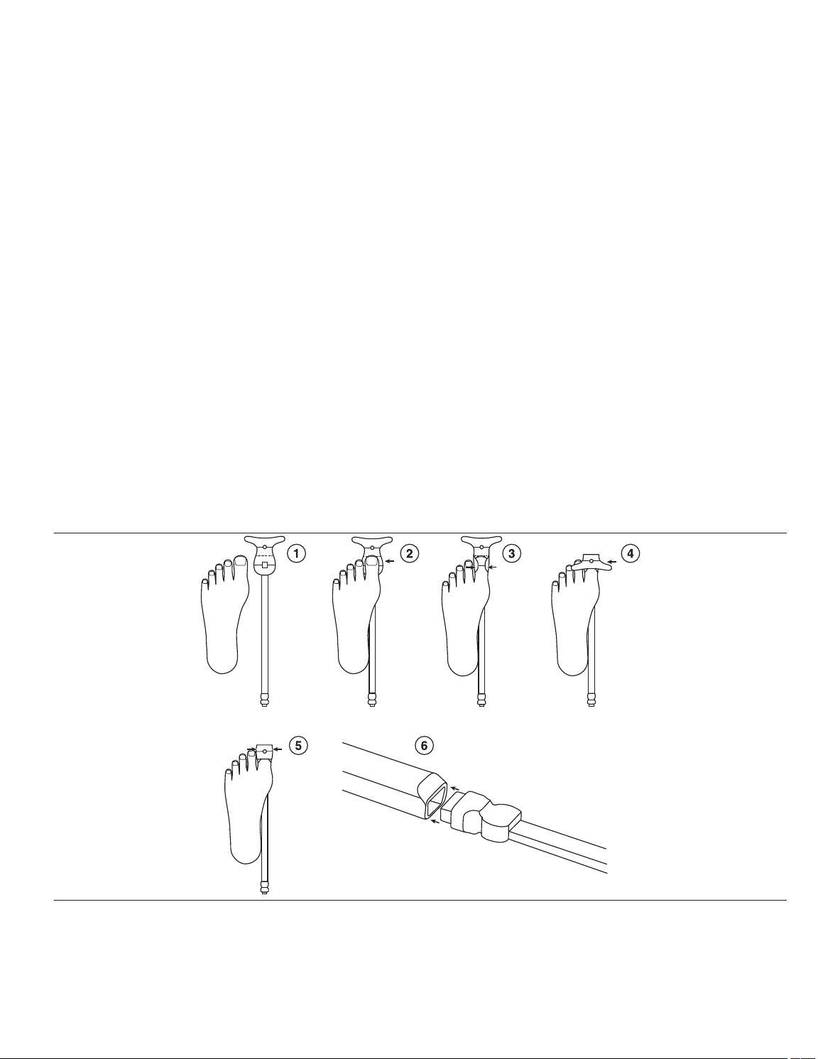
10.1 Attaching the sensor
The steps below are provided to help guide proper sensor placement and alignment.
1. Determine which digit will be used before attaching the sensor.
a. Ensure the digit is free from contaminants and does not have an open wound or compromised tissue.
b. Remove the sensor from the pouch.
c. Remove the backing from the sensor exposing the adhesive. See Figure 2 step 1.
2. Apply one side of the sensor according to Figure 2, step 2.
a. With an anterior-posterior (AP) view of the foot, locate the tip of the desired digit.
b. With an AP view, line the tip of the desired digit with the dashed line of the sensor.
c. Maintaining the alignment specified in Figure 2, step 2, affix the gray rectangular detector with small hole or aperture over the fleshy portion of the digit, opposite of the nail bed.
3. Fold over one side edge of the adhesive around the digit as shown in Figure 2, step 3.
4. Fold over the other side edge, circular light source, of the adhesive over the top of the digit and onto the nail bed as shown in Figure 2, step 4. Using the solid lines demarcating the source
and detector location, verify that the source and detector are approximately opposite one another on the digit.
5. Fold the wings of the side edge over the sensor as show in Figure 2, step 5.
6. Insert the connector of the sensor to the reusable cable as shown in Figure 2, step 6.
Figure 2. Attaching the sensor
Note: The images in Figure 2 show a dorsal view of the foot. The same steps and images are applicable for an analogous dorsal view of the hand. Some lines in the sensor images are
shown for reference and do not appear on the actual sensor.
7. When the sensor is ready for operation, START DISPLAY will be highlighted and available for selection.
Warning: Do not start the monitoring system unless the sensor is applied to a digit. Stop the monitoring system before removing the digit from the sensor. Failure to use the monitoring
system as described in this manual could result in exposure to laser radiation, which is potentially harmful to the eyes. Never stare into the laser beam.
8. Measurement times can be as short as 30 s and as long as four hours depending on the application.
10
Page 11

Warning: Ensure the sensor is not too tight, especially in the case of patients with poor perfusion. A sensor that is too tight or becomes too tight as a result of edema may lead to inaccurate
readings or tissue damage. Tissue damage may result by way of ischemia followed by subsequent pressure necrosis or skin erosion. The sensor site should be monitored frequently,
every 30 min, for signs of ischemia or any other form of tissue maladies.
10.2 Removing the sensor
Warning: During removal of the sensor, be careful of causing damage to the underlying and surrounding tissue where the sensor is attached.
Warning: Before removing the sensor from the digit, examine the digit and its surrounding tissue for any signs of damage or injury which may require special attention.
1. Disconnect the reusable cable from the tablet.
2. Remove the connector of the sensor to the reusable cable.
3. Unfold the wings on one side of the sensor.
4. Unfold the other side edge of the sensor up and over the top of the digit.
5. Unfold the edges of one side of the adhesive off the digit.
6. Lift one side of the adhesive off the fleshy portion of the digit.
10.3 FlowMet software
The sensor is controlled by custom software, which has been pre-installed onto the tablet. Open the software by tapping the FlowMet software icon (Figure 3) twice, which is located on the
desktop and taskbar. The user interface displays.
Figure 3. FlowMet software icon
11
Page 12
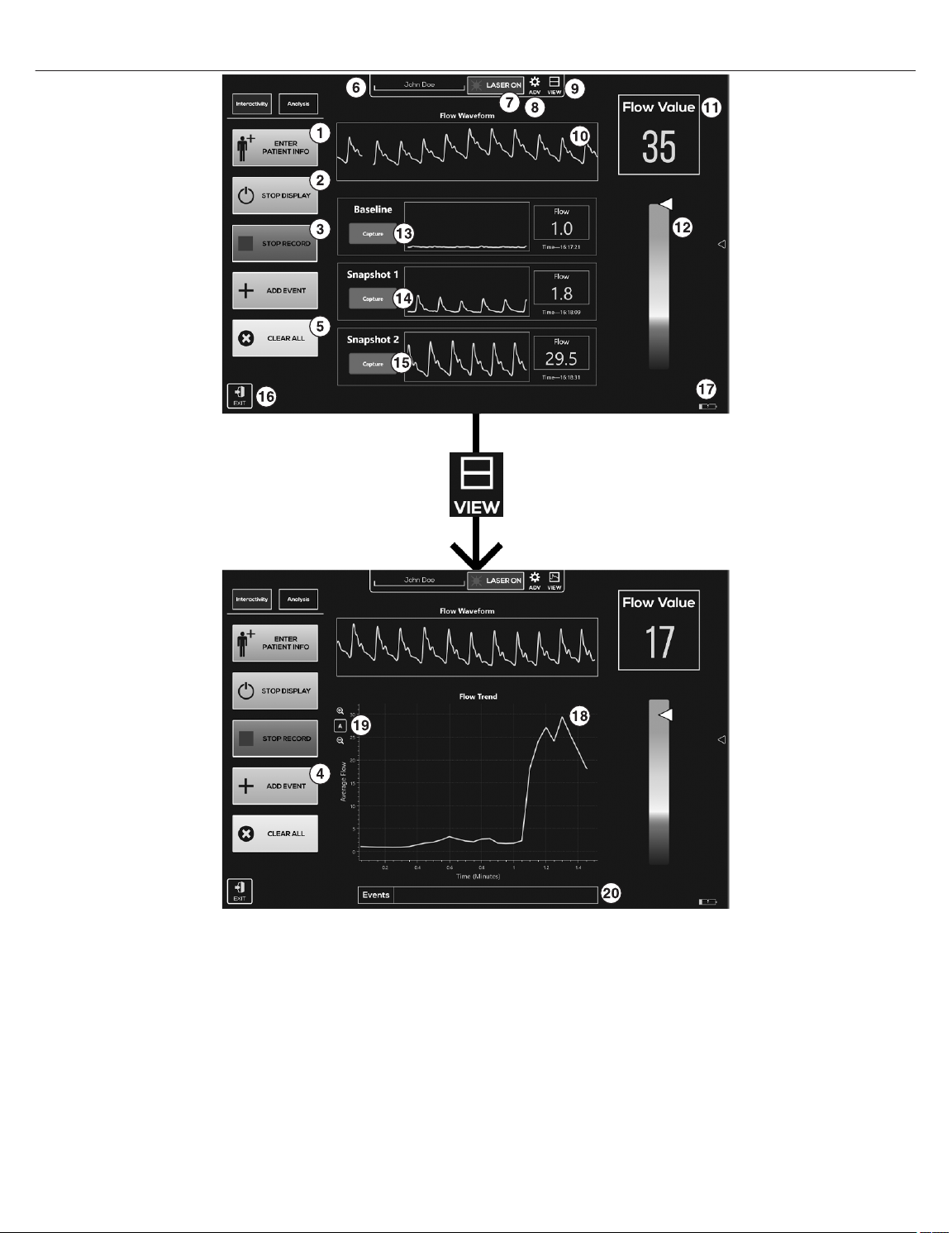
10.3.1 User interface summary
Figure 4. User interface summary
1 ENTER PATIENT INFO allows the user to add patient information (patient identification (ID)\side\location\digit number\date and time) and any additional notes.
2 Toggle START DISPLAY/STOP DISPLAY begins the output of flow information but will not record until RECORD TREND is tapped.
3 Toggle RECORD TREND/STOP RECORD to start or stop the recording of data. Automatically resets the time in the Flow Trend view, if chosen, to 0 for a new record, or the last recorded
time for a continuation.
4 ADD EVENT allows the user to demarcate specific time points in the Flow Trend view, if chosen.
5 CLEAR ALL clears displayed waveform snapshots, clears the plot in the Flow Trend area, and restarts the Flow Trend plot at 0 seconds.
6 Current patient ID or name. This entry can be changed within the ENTER PATIENT INFO.
7 Laser indicator, LASER ON, displays when the monitoring system is running and the laser is on. LASER OFF displays when the monitoring system is off and not running. Any time the
LASER ON is displayed, the sensor should be applied to a digit.
8 Toggle ADV displays advanced options dialogue. See Section 10.4, Advanced options, page 16 for more information.
9 VIEW changes how collected data is displayed between four views: waveform snapshots and Flow Waveform, Flow Trend, Flow Waveform, just Flow Waveform, and just Flow
Trend.
10 Flow Waveform area plots the current blood flow values.
11 Flow Value area indicates the current blood flow values.
12 Blood flow indicator bar gives a general idea of where the current flow values are on the spectrum of normal. This is a general indicator and does not represent a diagnosis or indicate
the presence of disease.
13 Capture collects and displays a snapshot of the current Flow Waveform, Flow Value, and time in the Baseline area. Pressing Capture again replaces the current data.
14 Capture collects and displays a snapshot of the current Flow Waveform, Flow Value, and time in the Snapshot 1 area. Pressing Capture again replaces the current data.
12
Page 13
15 Capture collects and displays a snapshot of the current Flow Waveform, Flow Value, and time in the Snapshot 2 area. Pressing Capture again replaces the current data.
16 EXIT exits the program.
17 Displays the current battery charge level and whether the battery is charging.
18 Flow Trend area indicates the average blood flow plotted over the entire measurement period.
19 Allows zoom in (+) on the Flow Trend data and zoom out (-) on the Flow Trend data, or allows the Flow Trend data to rescale automattically.
20 Events area displays the events added from the ADD EVENT option.
10.3.2 Data streaming and display
Tap START DISPLAY to begin real-time blood flow display. Flow data displays as a function of time in the upper plot of the Flow Waveform area. The Flow Waveform area plots the current
blood flow value.
Average flow is computed and plotted in the Flow Trend area. Averaged flow data continues to be appended until CLEAR ALL is tapped, which is located in the lower-left corner of the plot.
Blood flow index is computed from the collected real-time data and displayed in the blood Flow Value area.
The blood flow indicator bar on the right of the main user interface represents the blood flow with a simple colormap. The deep red at the bottom of the indicator bar indicates the minimum
measurable flow and the green at the top of indicator bar indicates the maximum measurable flow. The arrow on the indicator bar shows where the current averaged flow data being collected
fits along the range of measurable values.
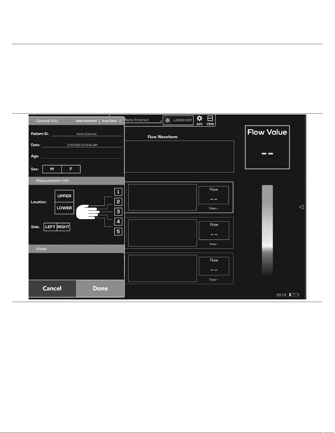
10.3.3 Entering patient information and recording Tapping ENTER PATIENT INFO displays a new interface where the user can input relevant patient information (patient ID\side\location\digit number\date and time.
Figure 5. Patient information
Once all desired information is added, tap Done. A “PatientInfo.xlsx” file is created once data recording begins. Files are saved in a folder based on patient ID and all the accompanying patient
parameters (patient\side\location\digit number\date and time).
Note: Each time a change is made in the patient information section and data is recorded, new files are created. The new files are automatically saved in a folder based on patient ID and patient
information (patient\side\location\digit number\date and time). This time and date is based upon the tablet time and date. Verify the accuracy of the time and date before recording data. If the
tablet time and date is not correct, manually set the time and date.
10.3.4 Patient data save location
Patient data is displayed by tapping START DISPLAY and saved by tapping RECORD TREND. Data continues to be saved until STOP RECORD is tapped.
Patient data save folders are created automatically and saved to the local C:\Users\FlowMet\FlowMet directory on the tablet.
Within the FlowMet folder, the labeling protocol is Patient ID\Side\Location\Digit Number\Date and Time. If no patient ID has been entered, None Entered displays at the top of the screen.
10.3.5 Patient data output A comma-separated value (CSV) spreadsheet titled “PatientInfo.csv” is generated for each new unique patient measurement session and automatically filled with entries from the ENTER
PATIENT INFO section.
The “PatientInfo.csv” file is saved to the C:\Users\FlowMet\FlowMet\Patient ID\Side_Location_Digit#\Date_Time directory on the tablet.
10.3.6 FlowMet.csv and FlowMet_Average.csv
In addition to the patient information file (PatientInfo.csv), a minimum of two other files (FlowMet.csv and FlowMet_Average.csv) are created during a single data recording session. These
files contain saved patient data.
Note: A “.csv” file can be imported into a Microsoft Excel file.
13
Page 14
FlowMet.csv
“FlowMet.csv” contains every data point sampled during the recording session.
FlowMet_Average.csv
“FlowMet_Average.csv” contains averaged flow data at a frequency of 0.33 Hz (3 s).
Note: Within the same recording session, each RECORD TREND and STOP RECORD sequence appends data to the “FlowMet.csv” file and the “FlowMet_Average.csv” file.
10.3.7 Selecting new patient parameters
If the patient information is not changed, every data recording sequence appends to the endpoint of the previous data recording sequence. If the user chooses a different digit or extremity on the
ENTER PATIENT INFO screen, a new folder and files are created within the patient ID folder.
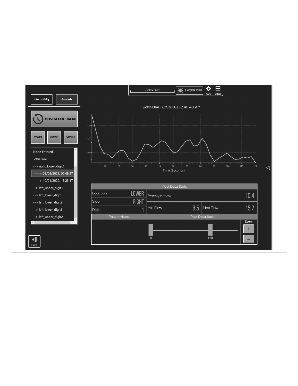
10.3.8 Analysis and data retrieval
The ANALYSIS feature allows the user to look at the past data that was just collected or previous data as well. When the user taps ANALYSIS, the default plot displays the data just collected.
To upload previous data, the user can browse through the directory tree under MOST RECENT TREND. Tapping a date in the directory tree immediately loads the corresponding plot, as well
as the data stats entered at the time of recording. See Figure 6 for an example of flow data.
Figure 6. STATS view
Unless the patient information is changed, each additional data recording sequence continues to append to the previous recording sequence. Analysis tab
to visualize captured snapshots alone (Figure 7) or with recorded flow data (Figure 8).
14
VIEW1 and VIEW2 can be used
Page 15

Figure 7. Analysis tab VIEW1
Figure 8. Analysis tab VIEW2
15
Page 16

10.4 Advanced options
The ADV (Advance) options icon accesses the advanced features and is password protected. These advanced features are intended to be accessed only by trained Medtronic personnel.
Accessing or adjusting these parameters on your own could compromise the functionality of the monitoring system and may void the warranty.
11 Cleaning
Warning: Not following the proper cleaning instructions stated within this manual could lead to permanent damage of the monitoring system or injury to the user or the patient.
Warning: Do not clean or service any parts of the monitoring system while the monitoring system is in use.
Caution: Do not soak or immerse any components of the monitoring system in any liquid solution.
Caution: Do not use undiluted bleach or any cleaning solution other than those recommended here.
Caution: Do not clean or sterilize by means of irradiation, steam, autoclave or ethylene oxide.
Caution: Do not clean with harsh solvents such as acetone or petroleum-based solutions.
Caution: Do not aggressively twist or pull on the cable while cleaning.
11.1 Instructions for cleaning reusable cable
Warning: The sensor is a single patient use disposable device and should not be cleaned or reused. The sensor may be repositioned on the same patient, during a single procedure, provided
the sensor provides adequate adhesion to the digit.
1. Before cleaning the reusable cable, ensure no components of the monitoring system are still attached to the patient.
2. Ensure the reusable cable is disconnected from both the sensor and the tablet.
3. Ensure the reusable cable is free from any visible defects or discolorations such as damage to the housing or exposed electrical components.
4. Wipe the surfaces and reusable cable with a soft cloth dampened with isopropyl alcohol, germicidal wipe, or a 10% bleach solution (household bleach [5.25% sodium hypochlorite]).
Alcohol prep pads comprised of 70% isopropyl alcohol are also recommended for the cleaning of the reusable cable.
5. Allow the reusable cable to dry before use and reconnecting.
11.2 Instructions for cleaning tablet, typepad, and power supply
Warning: Ensure all devices and components are off and unplugged prior to cleaning.
1. The tablet touchscreen can be cleaned with a soft, lint-free cloth. The cloth can be dampened or dry. If dampening the cloth, use either water or eyeglass cleaner. Do not pour liquid directly
onto the tablet touchscreen. Never use glass or harsh chemical cleaners. Screen cleaning wipes are acceptable for use as well.
2. The tablet typepad can be cleaned with a dry lint-free cloth or one that has been dampened in mild soap or water. The spine or magnetic connections can be cleaned with a soft, lint-free
cloth dampened with a small amount of isopropyl alcohol.
3. The tablet power supply can be cleaned with a dry lint-free cloth or one that has been dampened in mild soap or water.
12 Maintenance
The monitoring system requires no user calibration or periodic maintenance by either the user or the patient. Field repair of the internal circuitry is not possible. Do not attempt to open the case
or repair the electronics. Opening the chassis case will damage the monitoring system and void the warranty.
See Chapter 14, Troubleshooting, page 16 to address potential issues and possible solutions to determine whether or not maintenance is needed.
Warning: While there are no maintenance requirements for the monitoring system, do not clean or service any parts of the monitoring system while the monitoring system is in use.
13 Storage, transport and disposal
13.1 Storage and transport
When not in use, the FlowMet system is best stored and transported in the carrying case that was included with the system under the conditions specified below. If the Medtronic provided
case is not available, avoid long term storage in direct sunlight, for this could cause premature discoloration and degradation of various hardware components within the system. See
Section 6.2, Specifications, page 8 for transport and storage specifications.
13.2 Disposal of product
Caution: Dispose of the device in accordance with applicable laws, regulations, and hospital procedures, including those regarding biohazards, microbial hazards, and infectious substances.
Note: If the reusable cable, sensor, or any of the components within the monitoring system is contaminated with biological material, additional precautions may need to be taken to stay in
compliance with local laws.
14 Troubleshooting
14.1 Software
Generally, software related errors can be fixed by unplugging the device or restarting the software. The monitoring system was designed to be operated with the system plugged into the
designated Medtronic-supplied tablet power supply at all times. If the user is trying to operate the monitoring system using the internal battery source of the tablet alone, unexpected problems
may arise, especially when the battery power is low.
If the performance of the monitoring system is not consistent with expectations (for example, no clear pulse waveform is visible when one is expected), ensure there are no warning prompts
flashing.
14.2 Monitoring system warning prompts
Questionable signals may occur when too little or too much light is being detected by the monitoring system or if the digit does not extend far enough into the sensor.
Too little light displays the prompt, WARNING: Not enough light getting to the sensor. Please reposition. Too much light displays the prompt, WARNING: Too much light getting to the
sensor. Please reposition.
If the sensor gets disconnected at any junction, reusable cable to sensor, reusable cable to tablet, or by some other mechanism within the system, the warnings Reusable Cable
disconnected, please (re)connect Reusable Cable or Digit Flow Sensor not responsive. Please (re)connect Digit Flow Sensor and press “Re-initialize Sensor” to re-enable the
plot display appear in the middle of the screen.
14.3 Troubleshooting table
Issue
No or unchanging data being displayed. Software or hardware communication error.
Digit Flow Sensor is loose. Poor application of the adhesive within the sensor.
Microsoft Surface Pro Does Not Turn On. No power
Possible cause Remedy
Disconnect and reconnect reusable cable or sensor from tablet or reusable cable and restart tablet.
Adjustments within the adhesive tape is possible within the
same instance of initial use on the same patient, provided
proper adhesion is achievable.
Connect power supply (although the tablet can run on its
internal battery supply, it is best to have the system connected
to a power supply whenever possible.)
16
Page 17

Issue Possible cause Remedy
Software appears to be working but the “START” button is
not highlighted and selectable.
Digit Flow Sensor Too Much Light
Erratic pulse signal
Unexpected signal variation
Not Enough Light Too little light intensity.
Poor signal quality *Instances of what might appear to be
poor signal quality may also be an accurate depiction of a
patient’s vascular state and not be due to system malfunction.
Loss of pulse signal
*Instances of what might appear to be loss of pulse signal may
also be an accurate depiction of a patient’s vascular state and
not be due to system malfunction.
“Sensor was used on <date>” Sensor was previously used. Please replace the used sensor with a new sensor.
“Sensor cannot be used. Please connect a different sen-
sor. Error code 00X”
Contact Medtronic if problems persist.
Sensor is not properly attached to the reusable cable or tablet.
Defective reusable cable or sensor.
Too much light from an external source (direct sunlight, surgical lights, etc.).
Too much light intensity due to patient’s digit thickness.
Excessive motion (sensor or patient).
Excessive motion (tablet)
Software malfunction
Signals are accurate reflection of bodily changes in response
to other medical devices.
Signals are accurate reflection of extreme bodily changes
such as arterial occlusion, cardiac arrest, severe vasoconstriction, shock, etc.
Intravascular dyes such as indocyanine green, methylene
blue, etc. can affect the monitoring system measurements.
The device is in an area with high electromagnetic (EM) disturbances. Response to high-frequency electrosurgical interference and defibrillators.
Impeded blood flow due to sensor pressure.
*Severe vasoconstriction
Severe vasoconstriction is a natural bodily reaction. If the
monitoring system is being used within the proper operating
temperature the measurements are accurate.
Sensor information cannot be read. Please replace the sensor.
Ensure sure the reusable cable, USB to sensor is properly
attached to the sensor or tablet.
Test the system with a different reusable cable or sensor. If this
solves the problem, a replacement reusable cable can be
obtained from Medtronic.
Remove or redirect external light source.
Shield the sensor with an opaque material.
Place sensor on a thicker digit.
Offset the alignment of the source and detector.
Ensure the sensor has proper fixation or that the patient is not
being moved around.
Ensure the tablet is stationary when taking measurements. Do
not hold the tablet while taking measurements.
Restart the software.
Ensure the power supply is plugged in. System stability is
improved when the tablet is plugged into the power supply as
opposed to running off the battery.
Ensure these changes are not due to explainable circumstances such as the sensor being placed on an extremity that has
an arterial catheter, blood pressure cuff, intravascular line, etc.
There is no remedy for this situation. These are possibly
severe life-threating situations that require immediate medical
attention. The monitoring system is not intended to be used for
the diagnosis and treatment of these situations.
Once these dyes have been processed and filtered by the
body, proper flow readings will be available.
Turn off the device. Turn on the device. If the problem continues, relocate the device to an area with lower EM disturbances (away from electronic equipment such as cellular phones,
cordless phones, computers, radios, TVs, etc.).
Reposition the sensor.
Place sensor on a thinner digit.
Ensure the sensor is not so tight as to restrict blood flow.
*Poor signal quality may be a reflection of a patient’s vascular
state and thus no actionable remedy available.
Ensure the proper operating temperature is maintained. Environments that are too cold or too hot can naturally vary
patient’s flow values.
*Loss of pulse signal may be a reflection of a patient’s natural
vascular state and thus no actionable remedy available.
15 Guidance and manufacturer’s declaration
15.1 Electromagnetic compatibility (EMC) declaration tables
The monitoring system is intended for use in the electromagnetic environment specified in the EMC declaration tables. The user of the monitoring system should assure that they are used
in such an environment.
Note: The emission characteristics of this equipment make it suitable for use in industrial areas and hospitals (CISPR 11 Class A) that is professional healthcare environment. If it is used
in a residential environment (for which CISPR 11 Class B is normally required) this equipment might not offer adequate protection to radio communication service. The user might need to
take mitigation measures, such as relocating or re-orienting equipment.
Precautions concerning electromagnetic compatibility (EMC) must be taken for the monitoring system. This device complies with EN 60601-1-2:2015, IEC 60601-1-2:2014.
Under specific circumstances the monitoring system could potentially interfere with other electronics. If you think the monitoring system is causing interference, try turning the monitoring
system off and on to confirm the interference. You may correct interference by moving the monitoring system away from the affected device or plugging the monitoring system into a different
electrical outlet.
Warning: Portable RF communications equipment such as antennas, wireless microphones, cordless telephones, Wi-Fi transmitters, Bluetooth radio devices, etc. may affect the functionality
of the monitoring system and should not be placed or operated within 24 in (0.6 m) of the monitoring system and its components (tablet, cables, sensor, power supply, and accompanying
cables).
Warning: Do not stack any components or accessories of the monitoring system on or close to other equipment that may pose electromagnetic (EM) disturbances or vice versa. If this situation
is unavoidable, the monitoring system itself as well as the equipment it is in close proximity with should be tested prior to use to assure both the monitoring system and the other equipment
are functioning as intended.
Warning: Cables and accessories of the monitoring system may negatively affect the EMC performance of other devices or equipment and vice versa. Caution should be taken to ensure
proper isolated equipment placement.
Warning: The provided cables (reusable cable, power supply) were included in EMC testing to demonstrate compliance with regulatory requirements. Use of accessories other than those
provided by Medtronic may result in increased emissions or decreased immunity of the monitoring system and result in improper operation.
Warning: The components and accessories of the monitoring system should not be exchanged or replaced with parts not included with the monitoring system. Do not substitute the provided
power supply with an aftermarket power supply. Use of components or accessories not included with the monitoring system could result in inaccurate measurements or device non-operation.
Warning: As a light-based system, external lighting can sometimes have an effect on the monitoring system measurements. Generally, too much light exposure will trigger a warning from the
system; however, it is possible for external lighting to adversely affect measurements without triggering a system warning. As such, the user should be careful of lighting of the surroundings.
Some possible sources of light interference are direct sunlight, fluorescent lights, surgical lamps, infrared heating lamps, and bilirubin lamps. These situations can be remedied by shielding
the sensor with an opaque material if necessary.
Warning: Do not use during diathermy or electrocautery.
Warning: Be careful of unexpected signal variation due to radio frequency (RF) emitters (e.g. RFID). If there is suspicion of unexpected signal variation, see Chapter 14, Troubleshooting,
page 16 section.
Caution: Replacement parts or any other component substitutions should not be carried out without contacting Medtronic first.
17
Page 18

Warning: The tablet is portable but it is intended to be stationary during operation of the monitoring system.
Note: The monitoring system must be installed and put into service in accordance with the EMC information provided in the FlowMet Operator Manual provided by Medtronic. Portable and
mobile RF communications equipment can affect the behavior of the monitoring system. If this occurs, relocate or re-orient the monitoring system. The monitoring system complies with all
applicable and required standards for electromagnetic interference. The monitor does not normally affect nearby equipment and devices. The monitor is not normally affected by nearby
equipment and devices. However, it is good practice to avoid using the monitor in extremely close proximity to other equipment.
15.2 IEC 60601-1
The monitoring system complies with IEC 60601-1:2005 (3rd Edition) + Amendment 1:2012.
15.3 IEC 60825-1
The monitoring system complies with IEC 60825-1:2014 (3rd Edition).
Table 1. Compliance level for immunity tests Guidance and manufacturer’s declaration − electromagnetic immunity The FlowMet monitoring system is intended for use in the electromagnetic environment specified below. The user of the monitoring system should ensure that it is used
in such an environment.
Immunity tests EN/IEC 60601-1-2 test level Compliance level Electromagnetic environment − guidance
Electrostatic discharge (ESD) acc. to
IEC 61000-4-2
Rapid transient electrical Interferences/bursts
acc.to IEC 61000-4-4
Surges acc. to IEC 61000-4-5 ± 1 kV line(s) to lines(s)
Voltage dips, short interruptions and fluctuations of the supply voltage acc. to
IEC 61000-4-11
Magnetic field at the supply frequency
(50/60 Hz) acc. to IEC 61000-4-8
Radiated, radio-frequency, electromagnetic
field immunity test acc. to IEC 61000-4-3
Immunity to conducted disturbances, induced
by radio-frequency fields acc. to
IEC 61000-4-6
± 8 kV Contact discharge
± 15 kV Air discharge
± 2 kV for power lines
± 1 kV for input and output lines
100 kHz repetition
± 2 kV line(s) to earth
Voltage Dip:
Dip to 0% for 1 cycles @ 0° phase angle
Dip to 70% for 25/30 cycles @ 0° phase angle
Dropout to 0% for 0.5 cycles @ 0°, 45°, 90°,
135°, 180°, 225°, 270° & 315° phase angles
Voltage interruption:
100% for 250/300 cycles
30 A/m at 50 Hz/60 Hz 30 A/m at 50 Hz/60 Hz Power frequency magnetic fields should be at
3 V/m 80 MHz to 2.7 GHz
*Refer to table 2 for wireless Proximity RF field
test levels.
3 V
on 150 kHz to 80 MHz 1 kHz 80% AM
RMS
modulation 6 V
in ISM bands
RMS
± 8 kV Contact discharge
± 15 kV Air discharge
± 2 kV/1 kV
± 1 kV for input and output lines
100 kHz repetition
± 1 kV line(s) to line(s)
± 2 kV line(s) to earth
Voltage Dip:
Dip to 0% for 1 cycles @ 0° phase angle
Dip to 70% for 25/30 cycles @ 0° phase angle
Dropout to 0% for 0.5 cycles @ 0°, 45°, 90°,
135°, 180°, 225°, 270° & 315° phase angles
Voltage interruption:
100% for 250/300 cycles
Floors should be wood, concrete or ceramic
tile. If floors are covered with synthetic material, the relative humidity should be at least
30%.
Mains power quality should be that of a typical
commercial or hospital environment.
Mains power quality should be that of a typical
commercial or hospital environment.
Mains power quality should be that of a typical
commercial or hospital environment.
If the user of the monitoring system requires
continued operation during power mains
interruptions, it is recommended that the monitoring system be powered from an uninterruptible power supply or a battery.
levels characteristic of a typical location in a
typical commercial or hospital environment.
3 V/m 80 MHz to 2.7 GHz Refer to Table 3
3 V
on 150 kHz to 80 MHz 1 kHz 80% AM
RMS
modulation 6 V
in ISM bands
RMS
Refer to Table 3
Table 2. Test levels for proximity fields from RF wireless communications equipment
Test Frequency MHz Band MHz Service Modulation
IEC 60601-1-2 Test
Level V/m
Compliance Level V/m
385 380 - 390 TETRA 400 Pulse Modulation 18 Hz 27 27
450 430 - 470
GMRS 460
FRS 460
FM ± 5 kHz deviation 1 kHz
Sine Wave
28 28
710
704 - 787 LTE Band 13 & 17 Pulse Modulation 217 Hz 9 9745
780
810
870
800 - 960
930
1720
1845
1700 - 1990
1970
2450 2400 - 2570
GSM 800/900
TETRA 800
iDEN 820
CDMA 850
LTE Band 5
GSM 1800
CDMA 1900
DECT LTE Band 1, 3, 4, 25
UMTS
Bluetooth
WLAN 802.11 b/g/n
RFID 2450
LTE Band 7
Pulse Modulation 18 Hz 28 28
Pulse Modulation 217 Hz 28 28
Pulse Modulation 217 Hz 28 28
5240
5100 - 5800 WLAN 802.11 a/n Pulse Modulation 217 Hz 9 95500
5785
Table 3. Test levels for radiated and conducted immunity tests
Guidance and manufacturer’s declaration − electromagnetic immunity
The FlowMet monitoring system is intended for use in the electromagnetic environment specified below. The user of the monitoring system should ensure that it is used
in such an environment.
Immunity tests EN/IEC 60601-1-2 test level Compliance level Electromagnetic environment − guidance
Portable and mobile RF communications equipment should be used no
closer to any part of the monitoring system, including cables, than the recommended separation distance calculated from the equation applicable to
the frequency of the transmitter.
Recommended separation distance:
d= 1.2 √P
Where P is the nominal power of the transmitter in watts [W] according to
the information provided by the manufacturer of the transmitter and d is the
recommended separation distance in meters [m].
Conducted RF disturbances acc. to
IEC 61000-4-6
3 V
RMS
150 kHz to < 80 MHz
6 V
RMS
ISM bands 150 kHz to < 80 MHz
3 V
6 V
RMS
RMS
18
Page 19

Table 3. Test levels for radiated and conducted immunity tests (continued)
Guidance and manufacturer’s declaration − electromagnetic immunity
The FlowMet monitoring system is intended for use in the electromagnetic environment specified below. The user of the monitoring system should ensure that it is used
in such an environment.
Immunity tests EN/IEC 60601-1-2 test level Compliance level Electromagnetic environment − guidance
Field strengths from fixed RF transmitters, as determined by an electro-
Radiated RF disturbances acc. to
IEC 61000-4-3
3 V/m
80 MHz to 2.7 GHz
3 V/m
magnetic site survey,a should be less than the compliance level in each
frequency range.
d= 1.2 √P 80 MHz to < 800 MHz
d= 2.3 √P 800 MHz to < 2.7 GHz
Interference may occur in the vicinity of equipment marked with the following symbol:
b
Note: At 80 MHz and 800 MHz, the higher frequency range applies.
Note: These guidelines may not apply in all situations. The propagation of electromagnetic quantities is affected by absorptions and reflections of buildings, objects, and persons.
a
Field strengths from fixed transmitters, such as base stations for radio (cellular/cordless) telephones and land mobile radios, amateur radio, AM and FM radio broadcast and TV broadcast cannot be predicted theoretically
with accuracy. To assess the electromagnetic environment due to fixed RF transmitters, an electromagnetic site survey should be considered. If the measured field strength in the location in which the monitoring system
is used exceeds the applicable RF compliance level above, the monitoring system should be obser ved to verify normal operation. If abnormal performance is observed, additional measures may be necessar y, such as
re-orienting or relocating the monitoring system.
b
Over the frequency range 150 kHz to 80 MHz, field strengths should be less than 3 V/m.
Table 4. Recommended separation distances
Recommended separation distances between portable and mobile RF communications equipment and the monitoring system
The FlowMet monitoring system is intended for use in an electromagnetic environment in which radiated RF disturbances are controlled. The customer or user of the
monitoring system can help prevent electromagnetic interference by maintaining a minimum distance between portable and mobile RF communications equipment
(transmitters) and the monitoring system as recommended below, according to the maximum output power of the communications equipment.
Separation distance d [m] as a function of the transmitter frequency
Rated maximum output power of transmitter [W]
150 kHz to 80 MHz
d = 1.2 √P
80 MHz to 800 MHz
d = 1.2 √P
800 MHz to 2.7 GHz
d = 2.3 √P
0.01 0.12 0.12 0.23
0.1 0.38 0.38 0.73
1 1.2 1.2 2.3
10 3.8 3.8 7.3
100 12 12 23
For transmitters rated at a maximum output power not listed above, the recommended separation distance D in meters (m) can be estimated using the equation applicable to the frequency
of the transmitter, where P is the maximum output power rating of the transmitter in watts (W) according to the transmitter manufacturer.
Note: At 80 MHz and 800 MHz, the separation distance for higher frequency range applies.
Note: These guidelines may not apply in all situations. The propagation of electromagnetic quantities is affected by absorptions and reflections of structures, objects, and people.
Table 5. Emission class and group Guidelines and manufacturer’s declaration − electromagnetic emissions The FlowMet monitoring system is intended for use in the electromagnetic environment specified below. The customer or user of the monitoring system should ensure that
it is used in such an environment.
RF emissions as per CISPR 11 Group 1 The monitoring system uses RF energy only for its internal
RF emissions as per CISPR 11 Class A The monitoring system is suitable for use in all establishments
Harmonic emissions as per IEC 61000-3-2 Class A
Voltage fluctuations/flicker emissions as per IEC 61000-3-3 Complies
function. The customer or user of the monitoring system
should ensure that it is used in such an environment. Therefore, its RF emissions are very low and are not likely to cause
interference in nearby electronic equipment.
other than domestic and those directly connected to the public
low voltage power supply network that supplies buildings
used for domestic purposes.
16 Warranty
The FlowMet system has both reusable and single-use components which have different warranty periods and terms.
Medtronic, Inc. warrants to the initial purchaser, for a period of one (1) year from the date of purchase, the following reusable components of each FlowMet system to be free from defects in
materials and workmanship.
• Microsoft Surface Pro
• Microsoft Surface Pro Charger
• Microsoft Surface Typepad
• Reusable Cable
During the period of one (1) year, Medtronic will, at its discretion, replace reusable components of the FlowMet system (with a new or recertified unit), subject to the conditions and exclusions
stated herein. In the event that any reusable or disposable component of the FlowMet system is replaced, the warranty period will not be extended for that component which has been replaced.
Replacing one component of the FlowMet system does not affect the stipulated warranties on any other component within the system. These warranties shall be the sole and exclusive remedy
by the purchaser hereunder for any component, reusable, or disposable, of the FlowMet system delivered to the purchaser which is found to be defective in any manner whether such remedies
be in contract, tort or by law. These warranties exclude cost of delivery to and from Medtronic. All non-warranty work shall be done at Medtronic standard rates and charges in effect at the time
of delivery to Medtronic.
These warranties will not apply:
• If damage results from changes or modifications made to the FlowMet system by the user or third person after the date of manufacture.
• If there is sign or evidence of opening the FlowMet system.
• If damage results from service or repairs performed by any person or entity other than the manufacturer.
• If damage results from a Force Majeure or other event beyond the control of the manufacturer.
• If damage results from negligence or improper use, including but not limited to: improper storage, submersion in water or physical abuse, such as dropping or otherwise.
• If chassis case is opened.
These warranties shall be personal to the original user. Any sale, rental or other transfer or use of the product covered by these warranties to or by a user other than the original user shall cause
these warranties to immediately terminate.
19
Page 20

The remedies provided for in this warranty are the exclusive remedies available for any breach hereof. Neither Medtronic nor its suppliers or distributors shall be liable for any incidental,
consequential, or special damage of any nature or kind caused by or arising out of a defect in the product. All other warranties, expressed or implied, are excluded, including the warranties
of merchantability and fitness for a particular purpose.
20
Page 21

Page 22

Medtronic, Inc.
*M006465C001*
710 Medtronic Parkway
Minneapolis, MN 55432
USA
www.medtronic.com
+1 763 514 4000
LifeLine Technical Support, 24-hour consultation service:
1 877 526 7890
© 2021 Medtronic
M006465C001 A
2021-05-18
 Loading...