

Page 1

Evolut™ PRO+ System
Evolut™ PRO+ Transcatheter Aortic Valve
Evolut™ PRO+ Delivery Catheter System
Evolut™ PRO+ Loading System
Caution: Implantation of the Medtronic Evolut™ PRO+ system should be performed only
by physicians who have received Medtronic Evolut™ PRO+ training.
These devices are supplied sterile for single use only. After use, dispose of the delivery
catheter system and the loading system in accordance with local regulations and hospital
procedures. Do not resterilize.
Instructions for Use
Caution: Federal (USA) law restricts this device to sale by or on the order of a physician.
Page 2

Medtronic, Medtronic with rising man logo, and Medtronic logo are trademarks of
Medtronic. Third-party trademarks (“TM*”) belong to their respective owners. The following
list includes trademarks or registered trademarks of a Medtronic entity in the United States
and/or in other countries.
AOA™, Evolut™
Page 3

Sterile LC: Device has been sterilized using liquid chemical sterilants
according to EN/ISO 14160.
Explanation of symbols on package labeling
Use by
Consult instructions for use at this website
Do not reuse
Do not resterilize
Size
Serial number
Catalog number
Lower limit of temperature
Quantity
Lot number
Sterilized using ethylene oxide
Nonpyrogenic
MR Conditional
Do not use if package is damaged
Manufacturer
Date of manufacture
Model
For US audiences only
Keep dry
Keep away from sunlight
Manufactured in
Maximum guidewire diameter
1
Page 4

EVPROPLUS-23US
23 mm
17b/18 mm to 20 mm
53.4c/56.5 mm to 62.8 mm
EVPROPLUS-26US
26 mm
20 mm to 23 mm
62.8 mm to 72.3 mm
EVPROPLUS-29US
29 mm
23 mm to 26 mm
72.3 mm to 81.7 mm
EVPROPLUS-34US
34 mm
26 mm to 30 mm
81.7 mm to 94.2 mm
1.0 Device description
The Medtronic Evolut™ PRO+ system is a recapturable transcatheter aortic valve
replacement system, which includes the Evolut PRO+ transcatheter aortic valve
(bioprosthesis)a, the delivery catheter system (catheter), and the loading system (LS).
1.1 Evolut PRO+ transcatheter aortic valve (bioprosthesis)
Figure 1: 23 mm
bioprosthesis
Figure 2: 26 mm
bioprosthesis
Figure 3: 29 mm
bioprosthesis
Figure 4: 34 mm
bioprosthesis
The bioprosthesis is manufactured by suturing 3 valve leaflets and an inner skirt, made from
a single layer of porcine pericardium, onto a self-expanding, multi-level, radiopaque frame
made of Nitinol. The bioprosthesis has a porcine pericardial tissue outer skirt (wrap), which
is 1.5 cells in height and is sutured to the inflow section of the bioprosthesis. It is designed to
replace the native or surgical bioprosthetic aortic heart valve without open heart surgery and
without concomitant surgical removal of the failed valve.
The bioprosthesis is processed with alpha-amino oleic acid (AOA™), which is a compound
derived from oleic acid, a naturally occurring long-chain fatty acid. The bioprosthesis is
available for a range of aortic annulus diameters (Table 1).
Table 1: Patient anatomical criteria
Bioprosthesis model Size
Aortic annulus
diameter
Aortic annulus perimeter
(π × aortic annulus diameter)
a
The terms “bioprosthesis” and “transcatheter aortic valve” are synonymous terms and are used interchangeably
throughout the document to refer to the Evolut PRO+ device.
b
Diameter for surgical aortic valve (SAV)
c
53.4 mm for surgical bioprosthetic aortic annulus
2
Page 5

1.2 Delivery catheter system (catheter)
The catheter comes in different sizes. Refer to Table 2 for system compatibility. Refer to
Figure 5 and Figure 6 for catheter components.
The catheter facilitates the placement of the bioprosthesis within the annulus of the aortic
valve. The catheter assembly is flexible and compatible with a 0.035 in (0.889 mm)
guidewire. The distal (deployment) end of the system features an atraumatic, radiopaque
catheter tip and a capsule that covers and maintains the bioprosthesis in a crimped position.
The capsule includes a distal flare to enable the bioprosthesis to be partially or fully
recaptured after partial deployment. A stability layer is fixed at the handle and extends down
the outside of the catheter shaft. It provides a barrier between the retractable catheter and the
introducer sheath and vessel walls, thus enabling the catheter to retract freely. An Evolut
PRO+ inline sheath is assembled over the stability layer, which functions as a hemostatic
introducer sheath and minimizes the access site size to the capsule diameter. The 23-29 mm
catheter model is compatible with sheaths that can accommodate an 18 Fr (6.00 mm) device.
The 34 mm catheter model is compatible with sheaths that can accommodate a 22 Fr (7.33
mm) device.
The delivery catheter system consists of a catheter with an integrated handle to provide the
user with accurate and controlled deployment. The handle is on the proximal end of the
catheter and is used to load, deploy, recapture, and reposition the bioprosthesis. The handle
features a gray front grip used to stabilize the system. The deployment knob turns to deploy
the bioprosthesis precisely. Arrows on the deployment knob indicate the direction of rotation
required to deploy the bioprosthesis. If desired, the deployment knob can be turned in the
opposite direction to partially or fully recapture the bioprosthesis if the radiopaque capsule
marker band has not yet reached the distal end of the radiopaque paddle attachment. Once the
radiopaque capsule marker band reaches the distal end of the radiopaque paddle attachment,
it is at the point of no recapture. The deployment knob also features a trigger, which can be
engaged to make macro adjustments to the capsule position. A blue hand rest connects to the
deployment knob. The end of the handle features a tip-retrieval mechanism, which can be
used to withdraw the catheter tip to meet the capsule after the device has been fully deployed.
The catheter packaging contains an integrated loading bath and a removable tray with
3 rinsing bowls for loading and rinsing the bioprosthesis. The integrated loading bath features
a mirror, which aids in accurate placement of the bioprosthesis frame paddles during loading.
In addition to these features, the device packaging is swiveled and secured to facilitate the
bioprosthesis loading procedure.
3
Page 6

Figure 5: Catheter
1. Catheter tip
2. Capsule (Model D-EVPROP2329US: 18 Fr [6.0 mm] outer diameter [OD]; Model D-
EVPROP34US: 22 Fr [7.33 mm] OD)
3. Catheter shaft
4. Stability layer
5. Model D-EVPROP2329US: 14 Fr equivalent Evolut PRO+ inline sheath (18 Fr [6.0
mm] OD); Model D-EVPROP34US: 18 Fr equivalent Evolut PRO+ inline sheath (22
Fr [7.33 mm] OD)
6. Evolut PRO+ inline sheath flush port
7. Stability layer flush port
8. Gray front grip
9. Deployment knob
10. Trigger
11. Blue hand rest
12. Tip-retrieval mechanism
13. Capsule flush port
14. Wire lumen flush port
Figure 6: Catheter
1. 7.6 cm (Model D-EVPROP2329US); 7.7 cm Model D-EVPROP34US
2. 107 cm
3. 88.6 cm
4. 30 cm
4
Page 7

Figure 7: Catheter distal tray
Figure 8: Catheter proximal tray
1. Tray connector
2. Swivel hinge
3. Clip holder
4. Mirror
5. Integrated loading bath
6. Tray tab
7. Locking clip
8. Rinsing bowls
9. Tray tab holder
5
Page 8

EVPROPLUS-23US
EVPROPLUS-26US
EVPROPLUS-29US
EVPROPLUS-34US
L-EVPROP34US
D-EVPROP34US
1.3 Loading system (LS)
The LS compresses the bioprosthesis into the catheter. The LS comes in different sizes. Refer
to Table 2 for system compatibility. Refer to Figure 9 for components.
Figure 9: Evolut PRO+ LS
1. Catheter tip guide tube
2. Inflow cone
3. Backplate
4. Outflow cone
5. Capsule guide tube
6. Locking collar
Table 2: System compatibility
Bioprosthesis model Compatible LS models Compatible catheter models
L-EVPROP2329US D-EVPROP2329US
6
Page 9

2.0 Indications
The Medtronic Evolut PRO+ system is indicated for relief of aortic stenosis in patients with
symptomatic heart disease due to severe native calcific aortic stenosis who are judged by a
heart team, including a cardiac surgeon, to be appropriate for the transcatheter heart valve
replacement therapy.
The Medtronic Evolut PRO+ system is indicated for use in patients with symptomatic heart
disease due to failure (stenosed, insufficient, or combined) of a surgical bioprosthetic aortic
valve who are judged by a heart team, including a cardiac surgeon, to be at high or greater
risk for open surgical therapy (i.e., STS predicted risk of operative mortality score ≥8% or at
a ≥15% risk of mortality at 30 days).
7
Page 10

3.0 Contraindications
The Evolut PRO+ system is contraindicated in patients who cannot tolerate Nitinol (titanium
or nickel), an anticoagulation/antiplatelet regimen, or who have active bacterial endocarditis
or other active infections.
8
Page 11

4.0 Warnings and precautions
Carefully read all warnings, precautions, and instructions for use for all components of the
system before use. Failure to read and follow all instructions or failure to observe all stated
warnings could cause serious injury or death to the patient.
4.1 Warnings
General
• Implantation of the Medtronic Evolut PRO+ system should be performed only by
physicians who have received Medtronic Evolut PRO+ training.
• The transcatheter aortic valve is to be used only in conjunction with the delivery catheter
system and the loading system.
• System failure could occur if an incorrect combination of devices is used. Refer to
Table 2 for system compatibility.
• This procedure should only be performed where emergency aortic valve surgery can be
performed promptly.
• Do not use any of the Medtronic Evolut PRO+ system components if any of the
following has occurred:
• It has been dropped, damaged, or mishandled in any way
• The Use By date has elapsed
• Mechanical failure of the delivery catheter system and/or accessories may result in
patient complications.
Transcatheter aortic valve (bioprosthesis)
• Do not use the bioprosthesis if any of the following conditions is observed:
• There is any damage to the container (for example, cracked jar or lid, leakage,
broken or missing seals)
• The serial number tag does not match the container label
• The freeze indicator in the secondary package has activated
• The storage solution does not completely cover the bioprosthesis
• Accelerated deterioration of the bioprosthesis due to calcific degeneration may occur in:
• Children, adolescents, or young adults
• Patients with altered calcium metabolism (for example, chronic renal failure, or
hyperparathyroidism)
9
Page 12

4.2 Precautions
General
• Do not contact any of the Medtronic Evolut PRO+ system components with cotton or
cotton swabs.
• Do not expose any of the Medtronic Evolut PRO+ system components to organic
solvents, such as alcohol.
• Do not introduce air into the catheter.
• Do not expose the bioprosthesis to solutions other than the storage and rinse solutions.
• Do not add antibiotics or any other substance to either the storage or rinse solutions. Do
not apply antibiotics or any other substance to the bioprosthesis.
• Do not allow the bioprosthesis to dry. Maintain tissue moisture with irrigation or
immersion.
• Do not attempt to repair a damaged bioprosthesis.
• Do not handle or use forceps to manipulate the bioprosthesis leaflet tissue.
• Do not deform the bioprosthesis in excess of what is experienced during crimping,
loading, and implantation.
• Clinical long-term durability has not been established for the bioprosthesis. Evaluate
bioprosthesis performance as needed during patient follow-up.
• The safety and effectiveness of the Medtronic Evolut PRO+ system have not been
evaluated in the pediatric population.
• The safety and effectiveness of the bioprosthesis for aortic valve replacement have not
been evaluated in the following patient populations:
• Patients who do not meet the criteria for symptomatic severe native aortic stenosis
as defined below:
• Symptomatic severe high-gradient aortic stenosis: aortic valve area
≤1.0 cm2 or aortic valve area index ≤0.6 cm2/m2, a mean aortic valve
gradient ≥40 mmHg, or a peak aortic-jet velocity ≥4.0 m/s
• Symptomatic severe low-flow/low-gradient aortic stenosis: aortic valve
area ≤1.0 cm2 or aortic valve area index ≤0.6 cm2/m2; a mean aortic valve
gradient <40 mmHg; and a peak aortic-jet velocity <4.0 m/s
• With untreated, clinically significant coronary artery disease requiring
revascularization
• With a preexisting prosthetic heart valve with a rigid support structure in either
the mitral or pulmonic position if either the preexisting prosthetic heart valve
could affect the implantation or function of the bioprosthesis or the implantation
of the bioprosthesis could affect the function of the preexisting prosthetic heart
valve
10
Page 13

• Patients with liver failure (Child-Pugh Class C)
• With cardiogenic shock manifested by low cardiac output, vasopressor
dependence, or mechanical hemodynamic support
• Patients who are pregnant or breastfeeding
• The safety and effectiveness of the Evolut PRO+ bioprosthesis implanted within a failed
preexisting transcatheter bioprosthesis have not been demonstrated.
• Implanting the Evolut PRO+ bioprosthesis in a degenerated surgical bioprosthetic valve
(transcatheter aortic valve in surgical aortic valve [TAV in SAV]) should be avoided in
the following conditions. The degenerated surgical bioprosthetic valve presents with a:
• Significant concomitant paravalvular leak (between the prosthesis and the native
annulus), is not securely fixed in the native annulus, or is not structurally intact
(for example, wireform frame fracture)
• Partially detached leaflet that in the aortic position may obstruct a coronary
ostium
• Stent frame with a manufacturer’s labeled inner diameter <17 mm
• The safety and effectiveness of the bioprosthesis for aortic valve replacement have not
been evaluated in patient populations presenting with the following:
• Blood dyscrasias as defined: leukopenia (WBC <1000 cells/mm3),
thrombocytopenia (platelet count <50,000 cells/mm3), history of bleeding
diathesis or coagulopathy, or hypercoagulable states
• Congenital unicuspid valve
• Mixed native aortic valve disease (aortic stenosis and aortic regurgitation with
predominant aortic regurgitation [3–4+])
• Moderate to severe (3–4+) or severe (4+) mitral or severe (4+) tricuspid
regurgitation
• Hypertrophic obstructive cardiomyopathy
• New or untreated echocardiographic evidence of intracardiac mass, thrombus, or
vegetation
• Native aortic annulus size <18 mm or >30 mm per the baseline diagnostic
imaging or surgical bioprosthetic aortic annulus size <17 mm or >30 mm
• Transarterial access not able to accommodate the following:
• 22 Fr introducer sheath or the 18 Fr equivalent Evolut PRO+ inline
sheath.
• 18 Fr introducer sheath or the 14 Fr equivalent Evolut PRO+ inline sheath.
• Prohibitive left ventricular outflow tract calcification
• Sinus of Valsalva anatomy that would prevent adequate coronary perfusion
11
Page 14

• Significant aortopathy requiring ascending aortic replacement
• Moderate to severe mitral stenosis
• Severe ventricular dysfunction with left ventricular ejection fraction (LVEF)
<20%
• Symptomatic carotid or vertebral artery disease
• Severe basal septal hypertrophy with an outflow gradient
• A known hypersensitivity or contraindication to any of the following that cannot
be adequately pre-medicated:
Before use
• Aspirin or heparin (HIT/HITTS) and bivalirudin
• Ticlopidine and clopidogrel
• Nitinol (titanium or nickel)
• Contrast media
• Accelerated deterioration due to calcific degeneration of bioprostheses may occur in:
• Children, adolescents, or young adults
• Patients with altered calcium metabolism (for example, chronic renal failure, or
hyperparathyroidism)
• The bioprosthesis size must be appropriate to fit the patient’s anatomy. Proper sizing of
the device is the responsibility of the physician. Refer to Table 1 for available sizes.
Failure to implant a device within the sizing matrix could lead to adverse effects such as
those listed in Section 5.0.
• Patients must present with transarterial access vessels with diameters that are ≥5.0 mm
when using Model D-EVPROP2329US or ≥6.0 mm when using Model DEVPROP34US, or patients must present with an ascending aortic (direct aortic) access
site ≥60 mm from the basal plane.
• Implantation of the bioprosthesis should be avoided in patients with aortic root angulation
(angle between plane of aortic valve annulus and horizontal plane/vertebrae) of >30° for
right subclavian/axillary access or >70° for femoral and left subclavian/axillary access.
• For subclavian access, patients with a patent Left Internal Mammary Artery (LIMA) graft
must present with access vessel diameters that are either ≥5.5 mm when using Model DEVPROP2329US or ≥6.5 mm when using Model D-EVPROP34US. Use caution when
using the subclavian/axillary approach in patients with a patent Left Internal Mammary
Artery (LIMA) graft (for left subclavian/axillary approach only) or patent Right Internal
Mammary Artery (RIMA) graft (for right subclavian/axillary approach only).
• For direct aortic access, ensure the access site and trajectory are free of patent RIMA or a
preexisting patent RIMA graft.
12
Page 15

• For transfemoral access, use caution in patients who present with multiplanar curvature
of the aorta, acute angulation of the aortic arch, an ascending aortic aneurysm, or severe
calcification in the aorta and/or vasculature. If ≥2 of these factors are present, consider an
alternative access route to prevent vascular complications.
• Limited clinical data are available for transcatheter aortic valve replacement in patients
with a congenital bicuspid aortic valve who are deemed to be at low surgical risk.
Anatomical characteristics should be considered when using the valve in this population.
In addition, patient age should be considered as long-term durability of the valve has not
been established.
• Exposure to glutaraldehyde may cause irritation of the skin, eyes, nose, and throat. Avoid
prolonged or repeated exposure to the vapors. Use only with adequate ventilation. If skin
contact occurs, immediately flush the affected area with water (minimum of 15 minutes).
In the event of eye contact, flush with water for a minimum of 15 minutes and seek
medical attention immediately.
• The bioprosthesis and the glutaraldehyde storage solution are sterile. The outside of the
bioprosthesis container is nonsterile and must not be placed in the sterile field.
• Damage may result from forceful handling of the catheter. Prevent kinking of the catheter
when removing it from the packaging.
• This device was designed for single patient use only. Do not reuse, reprocess, or
resterilize this product. Reuse, reprocessing, or resterilization may compromise the
structural integrity of the device and/or create a risk of contamination of the device,
which could result in patient injury, illness, or death.
• Before catheter insertion, remove the loading stylet.
During use
• For direct aortic and subclavian access procedures, care must be exercised when using the
tip-retrieval mechanism to ensure adequate clearance to avoid advancement of the
catheter tip through the bioprosthesis leaflets during device closure.
• For direct aortic access procedures, use a separate introducer sheath; do not use the
Evolut PRO+ inline sheath. Maintain the Evolut PRO+ inline sheath at the proximal end
of the catheter throughout the procedure.
• Adequate rinsing of the bioprosthesis with sterile saline, as described in the Instructions
for Use, is mandatory before implantation. No other solutions, drugs, chemicals, or
antibiotics should ever be added to the glutaraldehyde or rinse solutions, as irreparable
damage to the leaflet tissue, which may not be apparent under visual inspection, may
result.
• During rinsing, do not touch the leaflets or squeeze the bioprosthesis.
• If a misload is detected, do not attempt to reload the bioprosthesis. Discard the entire
system. The valve, catheter, loading system, loading tray, and saline all must be replaced
with new sterile components.
13
Page 16

• Prevent contamination of the bioprosthesis, its storage solution, the catheter, and the LS
with glove powder.
• If a bioprosthesis and catheter have been removed from a patient, dispose of both the
bioprosthesis and catheter; do not attempt to reuse either component. Both the
bioprosthesis and catheter must be replaced with new sterile components.
• While the catheter is in the patient, ensure the guidewire is extending from the proximal
end of the catheter. Do not remove the guidewire from the catheter while the catheter is
inserted in the patient.
• There will be some resistance when the catheter is advanced through the vasculature. If
there is a significant increase in resistance, stop advancement and investigate the cause of
the resistance (for example, magnify the area of resistance) before proceeding. Do not
force passage. Forcing passage could increase the risk of vascular complications (for
example, vessel dissection or rupture).
• Use the deployment knob to deploy and recapture the bioprosthesis. Do not use the
trigger for deploying or recapturing because it could cause inaccurate placement of the
bioprosthesis.
• From annular contact to just before the point of no recapture, the bioprosthesis will
occlude cardiac output. Promptly deploy or recapture the valve during this occlusive
phase as prolonged obstruction or occlusion of blood flow may lead to hypotension,
bradycardia, conduction disturbance, congestive heart failure, pulmonary edema, or
death.
• If the radiopaque capsule marker band has not yet reached the distal end of the
radiopaque paddle attachment, the bioprosthesis can be recaptured or repositioned.
During deployment, the deployment knob provides a tactile indication as a notification
before the point of no recapture.
• Once the radiopaque capsule marker band reaches the distal end of the radiopaque paddle
attachment (point of no recapture), retrieval of the bioprosthesis from the patient (for
example, use of the catheter) is not recommended. Retrieval after the point of no
recapture may cause mechanical failure of the delivery catheter system, aortic root
damage, coronary artery damage, myocardial damage, vascular complications, prosthetic
valve dysfunction (including device malposition), embolization, stroke, and/or emergent
surgery.
• During deployment, the bioprosthesis can be advanced or withdrawn as long as annular
contact has not been made. Once annular contact is made, the bioprosthesis cannot be
advanced in the retrograde direction; recapture until the bioprosthesis is free from annular
contact, and then reposition in the retrograde direction. If necessary, and the radiopaque
capsule marker band has not yet reached the distal end of the radiopaque paddle
attachment, the bioprosthesis can be withdrawn (repositioned) in the antegrade direction.
However, use caution when moving the bioprosthesis in the antegrade direction.
Caution: Use the handle of the delivery system to reposition the bioprosthesis. Do not
use the outer catheter sheath.
14
Page 17

• Physicians should use judgment when considering repositioning a fully deployed
bioprosthesis (for example, using a snare, balloon, and/or forceps). Repositioning the
bioprosthesis is not recommended, except in cases where imminent serious harm or death
is possible (for example, coronary occlusion). Repositioning of a deployed valve may
cause aortic root damage, coronary artery damage, myocardial damage, vascular
complications, prosthetic valve dysfunction (including device malposition), embolization,
stroke, and/or emergent surgery.
• Do not attempt to retrieve or to recapture a bioprosthesis if any one of the outflow struts
is protruding from the capsule. If any one of the outflow struts has deployed from the
capsule, the bioprosthesis must be released from the catheter before the catheter can be
withdrawn.
• Ensure the capsule is closed before catheter removal.
• When using a separate introducer sheath, if increased resistance is encountered when
removing the catheter through the introducer sheath, do not force passage. Increased
resistance may indicate a problem and forced passage may result in damage to the device
and/or harm to the patient. If the cause of resistance cannot be determined or corrected,
remove the catheter and introducer sheath as a single unit over the guidewire, and inspect
the catheter and confirm that it is complete.
• Postprocedure, administer appropriate antibiotic prophylaxis as needed for patients at risk
for prosthetic valve infection and endocarditis.
• Postprocedure, administer anticoagulation and/or antiplatelet therapy per
physician/clinical judgment.
• Excessive contrast media may cause renal failure. Preprocedure, measure the patient’s
creatinine level. During the procedure, monitor contrast media usage.
• Conduct the procedure under fluoroscopy. Fluoroscopic procedures are associated with
the risk of radiation damage to the skin, which may be painful, disfiguring, and longterm.
• The safety and efficacy of the Evolut PRO+ bioprosthesis implanted within a
transcatheter bioprosthesis have not been demonstrated. However, in the event that the
Evolut PRO+ bioprosthesis must be implanted within a transcatheter bioprosthesis to
improve valve function, valve size and patient anatomy must be considered before
implantation of the Evolut PRO+ bioprosthesis to ensure patient safety (for example, to
avoid coronary obstruction).
Post-implant balloon dilatation considerations
If valve function or sealing is impaired due to excessive calcification or incomplete
expansion, a post-implant balloon dilatation (PID) of the bioprosthesis may improve valve
function and sealing. If the heart team determines that balloon dilatation is appropriate,
consider all of the following factors when selecting the dilatation parameters to ensure
patient safety:
• Balloon model
• Balloon size
15
Page 18

Evolut PRO+ size
23 mm
26 mm
29 mm
34 mm
Native annulus
17d/18
19
20
20
21
22
23
23
24
25
26
26
27
28
29
30
TAV waist
20
20
20
22
22
22
22
23
23
23
23
24
24
24
24
24
Maximum balloon
17d/18
19
20
20
21
22
23
23
24
25
26
26
27
28
28
28
Maximum balloon
16d/17
18
19
19
20
21
22
22
23
24
24
25
25
25
25
25
• Balloon position
• Inflation pressure
• Patient anatomy
Two primary factors must be considered when selecting a maximum balloon diameter for
post-implant balloon dilatation:
• To mitigate trauma to the annulus
o A compliant or semi-compliant balloon (for example, B. Braun Z-Med I™* /
Z-Med II™*, InterValve V8™*) should not exceed the diameter of the native
aortic annulus. For TAV in SAV, the balloon should not exceed the inner
diameter of the surgical bioprosthetic valve.
o A non-compliant balloon (for example, Bard TRUE™* Dilatation) should be
at least 1 mm smaller than the diameter of the native aortic annulus. For TAV
in SAV, the balloon should be at least 1 mm smaller than the inner diameter of
the surgical bioprosthetic valve.
• To mitigate trauma to the Evolut TAV bioprosthetic leaflets
o The maximum balloon size chosen for dilatation using a compliant or semi-
compliant balloon should not exceed the TAV waist diameter beyond the level
set forth in Table 3 with an applied inflation pressure of no greater than 2 atm.
o The maximum balloon size chosen for dilatation using a non-compliant
balloon should not exceed 1 mm more than the TAV waist diameter with an
applied inflation pressure of no greater than 2 atm (see Table 3).
(SAV inner)
diameter (in mm)
diameter (in mm)
diameter (in mm)
for compliant and
semi-compliant
balloons @ 2 atm
diameter (in mm)
for non-compliant
balloons @ 2 atm
Table 3: Post-implant balloon dilatation sizing
Caution: Overexpansion of the narrowest portion (waist) of the Evolut PRO+ TAV beyond
the levels set forth in Table 3 has been demonstrated through bench data to cause damage to
d
Diameter for surgical aortic valve (SAV)
16
Page 19

the bioprosthetic leaflets. Complaints of damage to the bioprosthetic leaflets during postimplant balloon dilatation have been reported in some clinical cases, resulting in moderate to
severe aortic insufficiency, which may be detected acutely or during follow-up.
It is important to note that the mechanical compliance properties of the selected balloon
influence the dilatation dynamics.
Balloons should not be inflated beyond 2 atm of applied pressure.
Compliant and semi-compliant (softer) balloons will more readily conform to the hourglass
profile of the TAV bioprosthesis at lower pressures, but must be inflated at pressures that
preserve the hourglass profile of the TAV.
Conversely, non-compliant (stiffer) balloons will achieve the nominal diameter during
inflation irrespective of the underlying annulus or TAV resistance and should be downsized
(see Table 3).
For additional instructions on the use of balloon catheter devices refer to the specific balloon
catheter manufacturer's labeling.
In the event that larger balloon diameters than those listed in Table 3 are required to expand
the Evolut PRO+ TAV due to clinically important residual aortic regurgitation or stenosis,
using “bailout” intraventricular balloon positioning when performing PID avoids expansion
of the narrowest portion (waist) of the Evolut PRO+ TAV. This can mitigate the risk of
leaflet damage. Dilatation with intraventricular balloon positioning should be performed with
caution in the setting of a smaller ventricle cavity, presence of LVOT calcification, or wire
positioning that interferes with mitral valve function, in order to avoid any unintended
balloon interaction with anatomy. The balloon’s length and diameter, along with the
individual patient anatomy, must be considered. Care should also be taken not to exceed the
annular diameters when performing PID with intraventricular balloon positioning (see Table
3).
In the event that a bailout PID with intraventricular balloon positioning is performed, the
nominal diameter of the balloon should not exceed the annular diameter when using
compliant or semi-compliant balloons; the nominal diameter of the balloon should be at least
1 mm smaller than the annular diameter when using non-compliant balloons.
4.3 Magnetic resonance imaging (MRI)
MRI may be used on the bioprosthesis only under specific conditions. See Section 6.2: MRI
Safety Information for more information.
17
Page 20

5.0 Potential adverse events
Potential risks associated with the implantation of the Evolut PRO+ bioprosthesis may
include, but are not limited to, the following:
• Death
• Myocardial infarction, cardiac arrest, cardiogenic shock, cardiac tamponade
• Coronary occlusion, obstruction, or vessel spasm (including acute coronary closure)
• Cardiovascular injury (including rupture, perforation, tissue erosion, or dissection of
vessels, ascending aorta trauma, ventricle, myocardium, or valvular structures that may
require intervention)
• Emergent surgical or transcatheter intervention (for example, coronary artery bypass,
heart valve replacement, valve explant, percutaneous coronary intervention [PCI],
balloon valvuloplasty)
• Prosthetic valve dysfunction (regurgitation or stenosis) due to fracture; bending (out-of-
round configuration) of the valve frame; underexpansion of the valve frame;
calcification; pannus; leaflet wear, tear, prolapse, or retraction; poor valve coaptation;
suture breaks or disruption; leaks; mal-sizing (prosthesis-patient mismatch); malposition
(either too high or too low)/malplacement
• Prosthetic valve migration/embolization
• Prosthetic valve endocarditis
• Prosthetic valve thrombosis
• Delivery catheter system malfunction resulting in the need for additional re-crossing of
the aortic valve and prolonged procedural time
• Delivery catheter system component migration/embolization
• Stroke (ischemic or hemorrhagic), transient ischemic attack (TIA), or other neurological
deficits
• Individual organ (for example, cardiac, respiratory, renal [including acute kidney failure])
or multi-organ insufficiency or failure
• Major or minor bleeding that may require transfusion or intervention (including life-
threatening or disabling bleeding)
• Vascular access-related complications (for example, dissection, perforation, pain,
bleeding, hematoma, pseudoaneurysm, irreversible nerve injury, compartment syndrome,
arteriovenous fistula, stenosis)
• Mitral valve regurgitation or injury
• Conduction system disturbances (for example, atrioventricular node block, left-bundle
branch block, asystole), which may require a permanent pacemaker
• Infection (including septicemia)
18
Page 21

• Hypotension or hypertension
• Hemolysis
• Peripheral ischemia
• Bowel ischemia
General surgical risks applicable to transcatheter aortic valve implantation:
• Abnormal lab values (including electrolyte imbalance)
• Allergic reaction to antiplatelet agents, contrast medium, or anesthesia
• Exposure to radiation through fluoroscopy and angiography
• Permanent disability
19
Page 22

6.0 Patient information
6.1 Registration information
A patient registration form is included in each bioprosthesis package. After implantation,
please complete all requested information. The serial number is located on both the package
and the identification tag attached to the bioprosthesis. Return the original form to the
Medtronic address indicated on the form and provide the temporary identification card to the
patient prior to discharge.
Medtronic will provide an Implanted Device Identification Card to the patient. The card
contains the name and telephone number of the patient’s physician as well as information
that medical personnel would require in the event of an emergency. Patients should be
encouraged to carry this card with them at all times.
6.2 MRI safety information
Nonclinical testing and modeling have demonstrated that the Medtronic Evolut PRO+
bioprosthesis is MR Conditional. A patient with this device can be safely scanned in an MR
system meeting the following conditions:
• Static magnetic field of 1.5 T and 3.0 T
• Maximum spatial field gradient of 2500 gauss/cm (25 T/m)
• Maximum MR system reported, whole body averaged specific absorption rate (SAR) of
2.0 W/kg (Normal Operating Mode)
Based on nonclinical testing and modeling, under the scan conditions defined above, the
Medtronic Evolut PRO+ bioprosthesis is expected to produce a maximum in vivo
temperature rise of less than 4.0°C after 15 minutes of continuous scanning. Based on
nonclinical data, the image artifact caused by the device will extend no greater than 7 mm
from the Medtronic Evolut PRO+ bioprosthesis when imaged with a gradient echo pulse
sequence and a 3.0 T MRI system.
Scanning under the conditions defined above may be performed immediately after
implantation.
The presence of other implants or medical circumstances of the patient may require lower
limits on some or all of the above parameters. For deployment of a Medtronic Evolut PRO+
bioprosthesis inside of a failed surgical bioprosthetic valve, consult the MRI labeling
pertaining to the failed valve for additional artifact information.
20
Page 23

7.0 How supplied
7.1 Packaging
The bioprosthesis is supplied sterile and nonpyrogenic in a glass container and a screw cap
with a liner. The outside of the container is nonsterile and must not be placed in the sterile
field. A freeze indicator is placed inside the labeled carton. If the freeze indicator has been
activated, do not use the bioprosthesis.
The catheter is packaged in a single-pouch configuration and sterilized with ethylene oxide
gas. The catheter is sterile if the package is undamaged and unopened. The outer surfaces of
the pouch are nonsterile and must not be placed in the sterile field.
The LS is packaged in a double-pouch configuration. The LS is sterile if the pouches are
undamaged and unopened. The outer surfaces of the outer pouch are nonsterile and must not
be placed in the sterile field. The LS is sterilized with ethylene oxide gas.
7.2 Storage
Store the bioprosthesis at room temperature. Avoid exposing to extreme fluctuations of
temperature. Avoid freezing. Appropriate inventory control should be maintained so that
bioprostheses with earlier Use By dates are implanted preferentially.
Store the catheter and LS in a cool, dry environment.
21
Page 24

8.0 Additional equipment
Note: While extensive, this equipment list is not meant to cover all possible scenarios.
Transesophogeal echocardiogram (TEE) or transthoracic echocardiography
(TTE) on standby
Temporary pacer insertion
• Temporary pacemaker lead
• Sterile sleeve for pacemaker lead
• Hemostatic vessel introducer sheath
• Temporary pacemaker generator
• Sterile temporary pacemaker-to-generator cable
If indicated, pulmonary artery catheter insertion
• Standard pulmonary artery catheter
• Hemostatic vessel introducer sheath
• Saline flush line connected to pressure transducer
Baseline aortography via radial, brachial, or femoral approach
• 5 Fr or 6 Fr pigtail angiographic catheter
• 6 Fr hemostatic vessel introducer sheath
• 2-port manifold with saline flush line and pressure tubing or transducer
• Power injector syringe
• Contrast media
• High-pressure power injector tubing
Predilatation of implant site
• 2-port manifold with saline flush and transducer
• 9 Fr hemostatic vessel introducer sheath and a 14 Fr, 18 Fr or 22 Fr hemostatic vessel
introducer sheath
Note: The 23-29 mm catheter model is compatible with sheaths that can accommodate
an 18 Fr (6.00 mm) device. The 34 mm catheter model is compatible with sheaths that
can accommodate a 22 Fr (7.33 mm) device.
• Standard length 0.035 in (0.889 mm) straight guidewire
• Appropriate suture-mediated closure system, if applicable
• Angiographic catheter
22
Page 25

• 0.035 in (0.889 mm) × 260 cm standard high support guidewire to be shaped with a
pigtail loop
• Balloon valvuloplasty catheters, ≤4 cm length × 18 mm, 20 mm, 22 mm or 23 mm, and
25 mm, 28 mm, and 30 mm diameters
• Inflation device or syringe and diluted 1:5 contrast media
Bioprosthesis implantation
• 18 Fr or 22 Fr hemostatic vessel introducer sheath
Note: The 23-29 mm catheter model is compatible with sheaths that can accommodate an
18 Fr (6.00 mm) device. The 34 mm catheter model is compatible with sheaths that can
accommodate a 22 Fr (7.33 mm) device.
Note: A separate introducer sheath is optional for transfemoral and subclavian access
procedures.
Standby supplies (must be available in the room)
• Pericardiocentesis tray
• 35 mm × 120 cm single loop snare
• Standard percutaneous coronary intervention (PCI) equipment
• 14 Fr and 18 Fr hemostatic vessel introducer sheaths
• Standard cardiac catheterization lab equipment
• Intra-aortic balloon pump (IABP)
23
Page 26

9.0 Instructions for use
9.1 Inspection and bioprosthesis loading procedure
Caution: Once the bioprosthesis is removed from its container and the catheter and LS are
removed from their packaging, ensure all subsequent procedures are performed in a sterile
field.
Caution: Do not allow the bioprosthesis to dry. Maintain tissue moisture with irrigation or
immersion.
9.1.1 Inspection before use and swivel tray setup
1. Before removing the bioprosthesis, catheter, or LS from its primary packaging,
carefully inspect the packaging for any evidence of damage that could compromise
the sterility or integrity of the device (for example, cracked jar or lid, leakage, broken
or missing seals, torn or punctured pouch).
Caution: Do not use after the Use By date or if there is evidence of damage.
Caution: Do not use the bioprosthesis if the freeze indicator has been activated.
2. Remove the product from the protective package.
3. Visually check that the product is free of defects. Do not use if any defects are noted.
4. Remove the locking clip attached to the rinsing bowls.
5. Remove the rinsing bowls from the integrated loading bath.
6. Remove the locking clips that connect the distal and proximal trays.
7. Lift the tray connector from the distal tray, and swivel the distal tray 180°
counterclockwise.
8. Clip the tray tab on the distal tray to the tray tab holder on the proximal tray.
9. Fill the integrated loading bath with cold, sterile saline (0°C to 8°C [32°F to 46°F]).
9.1.2 Preparation of the catheter and LS
1. Attach a 10 mL syringe filled with sterile saline to the capsule flush port on the
proximal end of the handle. Leave the syringe in place until loading is complete.
2. Carefully lift the distal end of the catheter to a near vertical orientation. To prevent
kinking, do not bend the catheter severely.
3. Open the capsule and expose the paddle attachment.
Note: Use the deployment knob to open the capsule completely until the paddle
attachment is fully exposed.
4. With the capsule held vertically, flush the capsule flush port. Verify that no catheter
leakage is observed during any of the flushing steps. If leakage is observed, use a new
system.
24
Page 27

5. Submerge the capsule completely in the cold saline bath while flushing the capsule
flush port. Continue flushing the capsule until it is completely submerged in the bath
to prevent air from entering the catheter (Figure 10).
Note: After the bioprosthesis has been loaded into the capsule, the capsule flush port
can no longer be flushed.
Figure 10
Note: The bioprosthesis, catheter, and LS may look slightly different from the figures
in Section 9.0. The functionality of the system is the same.
6. Secure a locking clip in the clip holder to angle the catheter tip into the integrated
loading bath.
7. Place the LS components in the integrated loading bath.
9.1.3 Bioprosthesis rinsing procedure
1. Fill each of the 3 rinsing bowls (provided within the packaging) with approximately
500 mL of fresh, sterile saline at ambient temperature (15°C to 25°C [59°F to 77°F]).
Caution: Do not handle or manipulate the bioprosthesis with sharp or pointed
objects. Use atraumatic forceps only.
2. Confirm the integrity of the primary bioprosthesis container. Remove the
bioprosthesis from its container by carefully grasping one of the bioprosthesis frame
paddles with a pair of blunt tipped forceps. Do not use the forceps to grasp the tissue
portion of the bioprosthesis. Let any remaining solution drain from the bioprosthesis
completely.
Note: Retain the container with the original solution. It may be needed to store and
return a rejected bioprosthesis.
3. Compare the serial number on the container with the serial number on the tag
attached to the bioprosthesis.
Caution: If the serial numbers do not match, do not use the bioprosthesis.
4. Carefully remove the serial number tag from the bioprosthesis and retain the tag.
5. Immerse the entire bioprosthesis in a sterile rinsing bowl.
6. Gently agitate the bioprosthesis by hand for 15 seconds to remove the glutaraldehyde
from the bioprosthesis.
7. Repeat steps 5 and 6 in one of the remaining rinsing bowls.
25
Page 28

8. Leave the bioprosthesis submerged in sterile saline in the third rinsing bowl until it is
ready to be loaded.
9.1.4 Bioprosthesis loading procedure
Perform the bioprosthesis loading procedure while the distal end of the catheter is immersed
in the integrated loading bath filled with cold, sterile saline (0°C to 8°C [32°F to 46°F]). The
bioprosthesis should remain immersed in saline during the loading process to minimize the
introduction of air into the loaded system.
Note: Confirm the LS and catheter sizes are compatible with the bioprosthesis size (Table 2).
Note: Refer to Figure 9 for Evolut PRO+ LS components.
Caution: Rapid capsule advancement can contribute to difficulties with loading the valve.
Slowly advancing the capsule helps facilitate successful loading.
1. Submerge and cool the bioprosthesis in the integrated loading bath filled with cold,
sterile saline.
2. Ensure that the capsule guide tube is fully open (unlocked) with the locking collar at
the proximal end of the capsule guide tube (Figure 11).
Figure 11
3. Advance the capsule guide tube over the catheter shaft toward the handle and across
the catheter tip (Figure 12).
Figure 12
4. Once the catheter tip has been crossed, fully advance the locking collar to the distal
end of the capsule guide tube until it is closed (locked).
5. Continue to advance the capsule guide tube over the catheter shaft towards the handle
until it contacts the distal end of the capsule (Figure 13).
Caution: Do not attempt to advance the capsule guide tube over the capsule; this will
prevent the capsule flare from expanding fully and prevent proper loading.
26
Page 29
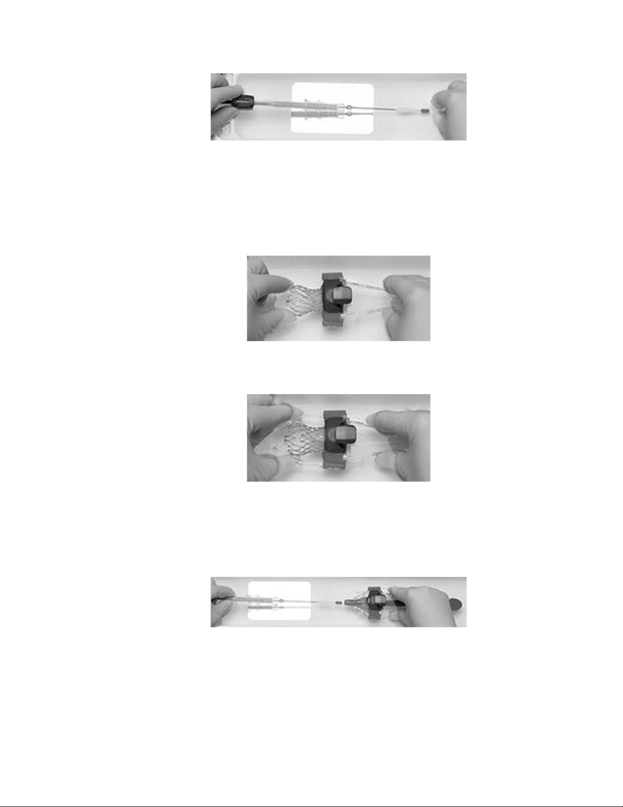
Figure 13
6. Ensure that the backplate has been inserted into the inflow cone and the exposed part
of the backplate is facing up.
7. Insert the inflow portion of the bioprosthesis frame into the inflow cone. Ensure that
the bioprosthesis frame paddle marked with a “C” is facing up and that the paddles
are aligned with the paddle attachment pockets (Figure 14).
Figure 14
8. Secure the outflow cone onto the inflow cone (Figure 15) until it locks.
Figure 15
9. Insert the catheter tip guide tube completely into the distal end of the inflow cone
(Figure 16). Inspect the outflow struts of the bioprosthesis and, if needed, manually
manipulate so that they are evenly spaced and the bioprosthesis frame paddles are
approximately 180° apart.
Figure 16
10. Insert the distal catheter tip into the catheter tip guide tube.
Note: Allow the loading tool to rest on the loading bath floor to ensure coaxial
alignment with the catheter to assist in seating the bioprosthesis frame paddles within
the paddle attachment pockets.
27
Page 30

11. Retract the catheter tip guide tube to set the bioprosthesis frame paddles into the
paddle attachment pockets (Figure 17).
Note: If the bioprosthesis frame paddles do not seat properly within the paddle
attachment pockets upon retracting the catheter tip guide tube, slightly manipulate the
position of the loading tool until paddle seating is achieved.
Note: If necessary, it is acceptable to manually compress the bioprosthesis frame
paddles with fingertips to help seat the paddles within the paddle attachment pockets.
Figure 17
Note: Ensure both bioprosthesis frame paddles are completely seated within the
paddle attachment pockets (Figure 18) before continuing to the next step.
Figure 18
12. Hold the loading tool stationary with one hand, and with the other hand manually
advance the capsule guide tube so that the distal section covers the paddle attachment
pockets and the top portion of the outflow struts (Figure 19).
Figure 19
28
Page 31

Use the mirror to ensure that both bioprosthesis frame paddles are positioned
correctly in the paddle attachment pockets and the outflow struts are within the distal
tip of the capsule guide tube (Figure 20).
Figure 20
13. Advance the capsule to cover the bioprosthesis frame paddles (Figure 21), pausing
when the capsule covers the proximal half of the paddles to confirm the paddles are
both still properly seated before advancing further.
Use the mirror to ensure that both paddles are captured in the capsule.
Figure 21
Caution: Do not advance the capsule over the bioprosthesis frame paddles unless
they are fully seated in the center of the paddle attachment pockets. Advancing the
capsule before the paddles are fully seated could damage the capsule and result in
emboli.
14. Advance the capsule to capture the bioprosthesis outflow struts (Figure 22).
Use the mirror to ensure that all bioprosthesis outflow struts are symmetrical and
captured in the capsule.
Figure 22
29
Page 32

15. Continue to advance the capsule until the distal end of the capsule guide tube covers
the distal end of the commissure pad of the bioprosthesis (Figure 23). The capsule
guide tube should completely cover the commissure pad.
Figure 23
16. Remove the backplate and the catheter tip guide tube from the outflow cone.
17. While holding the capsule guide tube stationary, advance the inflow cone to crimp the
inflow portion of the bioprosthesis frame until the outflow cone contacts the capsule
guide tube (Figure 24). During this step, the outflow cone contacts the locking collar
component and moves the locking collar to the proximal end of the capsule guide
tube.
Figure 24
Note: The capsule guide tube will be in the unlocked configuration after this step.
Note: Ensure the bioprosthesis frame axis is visually aligned (coaxial) with the inflow
cone axis during the insertion of the bioprosthesis into the inflow cone. Complete the
insertion of the bioprosthesis into the inflow cone in one uninterrupted movement.
18. Advance the capsule over the bioprosthesis until the capsule comes within 5 mm of
the catheter tip (Figure 25).
Figure 25
19. Remove the capsule guide tube together with the outflow cone and inflow cone from
the catheter (Figure 26).
30
Page 33

Figure 26
20. Advance the capsule to close the gap between the capsule and catheter tip completely
(Figure 27).
Caution: Stop advancing the capsule once the gap to the catheter tip is closed.
Advancing the capsule farther could damage the capsule.
Figure 27
21. Slightly rotate the deployment knob in the direction of the arrows to relieve stress.
Ensure that the capsule does not separate from the catheter tip.
Note: After the bioprosthesis has been loaded into the capsule, the capsule flush port
can no longer be flushed.
22. Visually and tactilely inspect the capsule for a misloaded bioprosthesis. The capsule
should be straight, smooth, and free of any bends, protrusions, or discolorations. If
any of these conditions are felt or observed, the bioprosthesis is likely to be
misloaded.
Note: If a misload is detected, do not attempt to reload the bioprosthesis. Discard the
entire system. The valve, catheter, loading system, loading tray, and saline must all be
replaced with new sterile components.
23. Attach a 10 mL syringe filled with sterile saline to the stability layer flush port on the
distal end of the handle and flush.
24. Remove the loading stylet from the guidewire lumen at the capsule.
25. Attach a 10 mL syringe filled with sterile saline to the wire lumen flush port on the
proximal end of the handle and flush.
26. Attach a 10 mL syringe filled with sterile saline to the Evolut PRO+ inline sheath
flush port and flush.
31
Page 34

27. Before inserting into a patient, visually inspect the loaded bioprosthesis under
fluoroscopy.
Note: If a misload is detected, do not attempt to reload the bioprosthesis. Discard the
entire system. The valve, catheter, loading system, loading tray, and saline must all be
replaced with new sterile components.
28. Leave the bioprosthesis submerged in sterile saline until implantation.
9.2 Bioprosthesis implantation
Note: Use systemic anticoagulation during the implantation procedure based on
physician/clinical judgment. If heparin is contraindicated, consider an alternative
anticoagulant.
9.2.1 Vascular access
Note: Vascular access should be achieved per standard practice (either percutaneously or via
surgical cutdown).
Note: The primary access artery will be used to introduce the Evolut PRO+ device and, if
predilatation is performed, the balloon catheter; the secondary access artery will be used to
introduce the reference pigtail.
1. Establish a central venous line. Insert a temporary pacemaker lead via the right
internal jugular vein (or other appropriate access vessel) per physician/clinical
judgment.
2. Insert an introducer sheath into the secondary access artery.
3. Insert an introducer sheath into the primary access artery.
4. Administer anticoagulant according to physician/clinical judgment. If heparin is
administered as an anticoagulant, check activated clotting time (ACT) and monitor
every 30 minutes after initial bolus of heparin. Maintain ACT ≥250 seconds.
Note: Anticoagulant may be administered at any time prior to this point, but avoid
delaying beyond this point.
9.2.2 Crossing the valve
1. Advance the graduated pigtail catheter to the ascending aorta and position the distal
tip in the noncoronary cusp of the aortic valve.
2. Identify the ideal annular viewing plane using contrast injections at various
angiographic angles.
Note: It is recommended that a dedicated individual prepare and operate the contrast
injector.
3. Insert an angiographic catheter over a standard J-tip guidewire into the primary access
sheath and advance to the ascending aorta.
4. Exchange the J-tip guidewire for a 0.035 in (0.889 mm) straight-tip guidewire.
Advance the straight-tip guidewire across the aortic valve into the left ventricle (LV).
32
Page 35

5. After crossing the aortic valve with the guidewire, advance the angiographic catheter
into the LV.
6. Exchange the straight-tip guidewire for an exchange length J-tip guidewire.
7. Exchange the angiographic catheter for a 6 Fr pigtail catheter.
8. Remove the guidewire and connect the catheter to the transducer. Using both
catheters, record the aortic pressure gradient.
9. Using a right anterior oblique (RAO) projection, advance the previously pigtail-
shaped, 0.035 in (0.889 mm) high support guidewire through the pigtail catheter and
position in the apex of the LV.
10. Remove the pigtail catheter while maintaining guidewire position in the LV.
9.2.3 Predilatation of the implant site
Note: The need for predilatation of the native valve is determined by the heart team.
Predilatation may be useful to prepare the valve for crossing by the delivery catheter system
and implantation of the transcatheter valve but may also confer some additional risk to the
patient (for example, liberation of embolic debris, damage to the tissue, or perforation of the
aortic root). Patient anatomical characteristics (for example, bicuspid anatomy, excessive or
asymmetric leaflet calcification, and possible leaflet fusion) should be considered by the
heart team when evaluating and determining the risk/benefit of predilatation and treatment
plan for each patient.
Information for failed surgical bioprosthetic valve: Balloon predilatation of a stenotic
surgical aortic bioprosthetic valve has not been evaluated. In cases where there is severe
stenosis, predilatation of the surgical aortic bioprosthetic valve may be done at the discretion
of the heart team and the steps used are identical to native valve predilatation.
1. Insert the valvuloplasty balloon through the introducer sheath in the primary access
artery and advance it to the ascending aorta.
2. Reposition the angiographic equipment to the ideal viewing plane. Position the
valvuloplasty balloon across the valve, while maintaining strict fluoroscopic
surveillance of the distal tip of the guidewire in the LV.
3. Perform balloon valvuloplasty per standard practice and remove the valvuloplasty
balloon while maintaining guidewire position across the aortic valve.
9.2.4 Deployment
1. Insert the device over the 0.035 in (0.889 mm) guidewire with the delivery catheter
flush ports oriented at 3 o'clock (toward the left side of the patient) to better facilitate
commissure alignment (flush ports shown in Figure 5, callouts 7 and 13). Insert the
catheter tip and capsule through the access site, while maintaining the Evolut
PRO+ inline sheath tip against the proximal end of the capsule. Then, insert the
Evolut PRO+ inline sheath through the access site, maintaining contact with the
capsule. When advancing the delivery system, allow the catheter handle to rotate
33
Page 36

freely after insertion of the system. Maintain strict fluoroscopic surveillance of the
guidewire in the LV.
Note: The 23-29 mm catheter model is compatible with introducer sheaths that can
accommodate an 18 Fr (6.00 mm) device. The 34 mm catheter model is compatible
with introducer sheaths that can accommodate a 22 Fr (7.33 mm) device.
Note: For transfemoral and subclavian access procedures, a separate introducer
sheath is optional. For direct aortic access procedures, use a separate introducer
sheath; do not use the Evolut PRO+ inline sheath. Maintain the Evolut PRO+ inline
sheath at the proximal end of the catheter throughout the procedure.
2. Under fluoroscopic guidance, advance the catheter over the guidewire to the aortic
annulus. To assist capsule advancement, the capsule orientation may be adjusted by
rotating the handle a quarter turn before the capsule crosses into the arch. If
adjustment to capsule orientation is required after crossing the arch, withdraw the
system to the descending aorta and rotate a quarter turn before readvancing.
Caution: Stop handle rotation if resistance is encountered or the capsule does not
respond to rotation under fluoroscopic visualization. Do not rotate the handle when
the capsule is at or beyond the arch. Continued attempts to rotate the capsule during
resistance may result in product failure and/or patient harm.
Caution: There will be some resistance when the catheter is advanced through the
vasculature. If there is a significant increase in resistance, stop advancement and
investigate the cause of the resistance (for example, magnify the area of resistance)
before proceeding. Do not force passage. Forcing passage could increase the risk of
vascular complications (for example, vessel dissection or rupture).
Caution: Persistent force on the catheter can cause the catheter to kink, which could
increase the risk of vascular complications (for example, vessel dissection or rupture).
Note: When crossing the aortic arch, it is critical that the guidewire is controlled to
prevent it from moving forward. Without proper management of the distal tip of the
guidewire, the guidewire could move forward and cause trauma to the LV.
3. Advance the device through the valve. Perform an angiogram to confirm that the
pigtail catheter is in position within the noncoronary cusp of the aortic root.
Fluoroscopically identify the appropriate landmarks.
4. Position the catheter so that the bioprosthesis is at the recommended target depth of
3 mm relative to the valve annulus. If the implant depth is <1 mm or >5 mm, consider
recapture (Section 9.2.5).
Caution: Bioprosthesis implant depth <1 mm may contribute to an increased risk of
prosthetic valve migration. Bioprosthesis implant depth >5 mm may contribute to an
increased risk of conduction disturbances, which may require a permanent
pacemaker.
Note: For surgical bioprosthetic valves, consider the features of the valve when
determining the optimal placement of the bioprosthesis.
Note: Physicians should consider patient anatomy when determining implant depth.
34
Page 37

5. To deploy the bioprosthesis, rotate the deployment knob in the direction of the
arrows. The capsule retracts and exposes the bioprosthesis. Continue deploying the
bioprosthesis in a controlled manner, adjusting valve position as necessary and noting
the position of the radiopaque capsule marker band and paddle attachment.
Warning: Use the deployment knob to deploy and recapture the bioprosthesis. Do
not use the trigger for deploying or recapturing because it could cause inaccurate
placement of the bioprosthesis.
Note: Consider using controlled pacing (90 to 120 bpm) because it may increase
valve stability during this stage of deployment, especially in patients with larger
anatomies.
Note: Slight antegrade repositioning of a partially deployed bioprosthesis (before the
radiopaque capsule marker band reaches the distal end of the radiopaque paddle
attachment) can be achieved by carefully withdrawing the catheter.
Caution: Use the catheter handle to reposition the bioprosthesis. Do not use the outer
catheter shaft.
6. Before the radiopaque capsule marker band reaches the distal end of the radiopaque
paddle attachment, evaluate the bioprosthesis position.
Note: When the bioprosthesis is approximately 2/3 deployed, the deployment knob
provides a tactile indication as a notification before the point of no recapture. Once
the radiopaque capsule marker band reaches the distal end of the radiopaque paddle
attachment, it is at the point of no recapture.
7. Either complete bioprosthesis deployment or initiate bioprosthesis recapture.
Note: Shortly after annular contact, the blood pressure will be reduced until
approximately the 2/3 deployment point, when the bioprosthesis leaflets are exposed
and are functioning.
9.2.5 Bioprosthesis recapture (optional)
The bioprosthesis is recapturable during deployment before the radiopaque capsule marker
band reaches the distal end of the radiopaque paddle attachment. Deployment of the
bioprosthesis can be attempted 3 times. If the bioprosthesis is recaptured a third time, it must
be removed from the patient.
1. Rotate the deployment knob in the opposite direction of the arrows to recapture the
bioprosthesis. A partially recaptured bioprosthesis can be repositioned or fully
recaptured.
Warning: Use the deployment knob to deploy and recapture the bioprosthesis. Do
not use the trigger for deploying or recapturing because it could cause inaccurate
placement of the bioprosthesis.
2. To fully recapture the bioprosthesis, continue rotating the deployment knob until the
gap between the capsule and catheter tip is closed.
Caution: Stop advancing the capsule once the gap between the capsule and the
catheter tip is closed. Advancing the capsule farther could damage the capsule.
35
Page 38

3. Reposition the recaptured bioprosthesis at the recommended target depth of 3 mm
relative to the valve annulus. If the implant depth is <1 mm or >5 mm, consider
recapture.
Caution: Bioprosthesis implant depth <1 mm may contribute to an increased risk of
prosthetic valve migration. Bioprosthesis implant depth >5 mm may contribute to an
increased risk of conduction disturbances, which may require a permanent
pacemaker.
Note: For surgical bioprosthetic valves, consider the features of the valve when
determining the optimal placement of the bioprosthesis.
Note: Physicians should consider patient anatomy when determining implant depth.
4. Redeploy the bioprosthesis (Section 9.2.4, steps 5 and 6).
5. Either complete bioprosthesis redeployment or initiate bioprosthesis recapture. If the
bioprosthesis has been recaptured 3 times, withdraw the recaptured bioprosthesis.
Note: Shortly after annular contact, the blood pressure will be reduced until
approximately the 2/3 deployment point, when the bioprosthesis leaflets are exposed
and are functioning.
9.2.6 Postdeployment
1. Perform an angiogram to assess the location of the bioprosthesis.
2. Under fluoroscopic guidance, confirm that the catheter tip is coaxial with the inflow
portion of the bioprosthesis.
3. Withdraw the catheter to the aorta while maintaining guidewire position.
Note: For transfemoral access, withdraw the catheter until the catheter tip is
positioned in the descending aorta. For direct aortic access and subclavian access,
withdraw the catheter until the catheter tip is close to the distal tip of the introducer
sheath.
4. Under fluoroscopic guidance, close the catheter capsule.
Caution: Close the capsule until it is aligned with the catheter tip. Do not overcapture
the catheter tip, because it could interfere with catheter withdrawal through the
introducer sheath or cause vessel trauma upon removal.
Caution: Ensure the capsule is closed before catheter removal.
Caution: When using a separate introducer sheath, if increased resistance is
encountered when removing the catheter through the introducer sheath, do not force
passage. Increased resistance may indicate a problem and forced passage may result
in damage to the device and/or harm to the patient. If the cause of resistance cannot
be determined or corrected, remove the catheter and introducer sheath as a single unit
over the guidewire, and inspect the catheter and confirm that it is complete.
5. Withdraw the catheter until the capsule meets the distal end of the Evolut
PRO+ inline sheath.
Note: For direct aortic access procedures, maintain the Evolut PRO+ inline sheath at
the proximal end of the catheter.
36
Page 39

6. Withdraw the catheter and Evolut PRO+ inline sheath together, and dispose of the
device in accordance with local regulations and hospital procedures.
7. Advance a 6 Fr pigtail catheter over the guidewire into the LV.
8. Remove the guidewire and connect the pigtail catheter to the transducer.
9. Using both pigtail catheters, record aortic pressure gradient.
10. Remove the 6 Fr pigtail over a standard, J-tip guidewire.
11. Perform a post-implant aortogram with the reference pigtail to ensure coronary
patency and assess aortic regurgitations.
Caution: Overexpansion of the narrowest portion (waist) of the Evolut PRO+ TAV
beyond the levels set forth in Table 3 has been demonstrated through bench data to
cause damage to the bioprosthetic leaflets. Complaints of damage to the bioprosthetic
leaflets during post-implant balloon dilatation have been reported in some clinical
cases, resulting in moderate to severe aortic insufficiency, which may be detected
acutely or during follow-up.
12. Remove the introducer sheath (if used) and complete the puncture site closure per
standard practice.
13. Perform contrast angiography to verify the absence of any vascular complications.
14. Remove the reference pigtail catheter over a standard guidewire. Remove the 6 Fr
introducer sheath and close the access site per standard practice.
15. Administer anticoagulation and/or antiplatelet therapy as required according to
physician/clinical judgment.
37
Page 40

10.0 Return of explanted bioprostheses
Medtronic is interested in obtaining recovered bioprostheses. Specific pathological studies of
the explanted bioprosthesis will be conducted under the direction of a consulting pathologist.
A written summary of the findings will be returned to the physician. To obtain a product
return kit, contact a Medtronic distribution center or a Medtronic Representative. If a kit is
not available, place the explanted bioprosthesis in a container of glutaraldehyde or 10%
buffered formalin immediately after excision. For further instructions on the return of an
explanted device, contact a Medtronic Representative.
38
Page 41

11.0 Clinical studies
Information regarding clinical studies and post-approval studies that are applicable to Evolut
PRO+ are available on the Medtronic Manual Library website:
1. Point your browser to www.medtronic.com/manuals.
2. Select the geography and language, and then search by product name for Evolut
PRO+. The instructions for use and premarket and post-approval study summaries are
listed. The clinical study summaries include the following: study name, applicable
device, patient population and indication, sample size, and follow-up duration.
If you do not have web access, you can order printed copies of the clinical study summaries
from your Medtronic representative or by calling the toll-free number located on the back
cover.
39
Page 42

12.0 Disclaimer of warranty
The following disclaimer of warranty applies to United States customers only:
DISCLAIMER OF WARRANTY
ALTHOUGH THE MEDTRONIC EVOLUT™ PRO+ TRANSCATHETER AORTIC
VALVE (MODELS EVPROPLUS-23US, EVPROPLUS-26US, EVPROPLUS-29US,
AND EVPROPLUS-34US), EVOLUT PRO+ DELIVERY CATHETER SYSTEM
(MODEL D-ENVPROP2329US AND D-EVPROP34US), EVOLUT PRO+ LOADING
SYSTEM (MODELS L-EVPROP2329US AND L-EVPROP34US), HEREAFTER
REFERRED TO AS “PRODUCT”, HAVE BEEN MANUFACTURED UNDER
CAREFULLY CONTROLLED CONDITIONS, MEDTRONIC HAS NO CONTROL
OVER THE CONDITIONS UNDER WHICH THIS PRODUCT IS USED.
MEDTRONIC THEREFORE DISCLAIMS ALL WARRANTIES, BOTH EXPRESS
AND IMPLIED, WITH RESPECT TO THE PRODUCT, INCLUDING, BUT NOT
LIMITED TO, ANY IMPLIED WARRANTY OF MERCHANTABILITY OR
FITNESS FOR A PARTICULAR PURPOSE. MEDTRONIC SHALL NOT BE
LIABLE TO ANY PERSON OR ENTITY FOR ANY MEDICAL EXPENSES OR ANY
DIRECT, INCIDENTAL OR CONSEQUENTIAL DAMAGES CAUSED BY ANY
USE, DEFECT, FAILURE OR MALFUNCTION OF THE PRODUCT, WHETHER A
CLAIM FOR SUCH DAMAGES IS BASED UPON WARRANTY, CONTRACT,
TORT OR OTHERWISE. NO PERSON HAS ANY AUTHORITY TO BIND
MEDTRONIC TO ANY REPRESENTATION OR WARRANTY WITH RESPECT
TO THE PRODUCT.
The exclusions and limitations set out above are not intended to, and should not be construed
so as to, contravene mandatory provisions of applicable law. If any part or term of this
DISCLAIMER OF WARRANTY is held by any court of competent jurisdiction to be illegal,
unenforceable or in conflict with applicable law, the validity of the remaining portion of the
DISCLAIMER OF WARRANTY shall not be affected, and all rights and obligations shall be
construed and enforced as if this DISCLAIMER OF WARRANTY did not contain the
particular part or term held to be invalid.
40
Page 43

Medtronic, Inc.
© 2022 Medtronic
710 Medtronic Parkway
Minneapolis, MN 55432
USA
www.medtronic.com
+1 763 514 4000
LifeLine Technical Support,
24-hour consultation service:
1 877 526 7890
Protected by one or more of the following United States Patents: 8,226,710 and 7,914,569.
*M987524A001*
M987524A001 Rev. J
 Loading...