

Medtronic EC300 User Manual
Integrated Power Console (IPC®) System
MODEL: EC300
User’s Guide

CUSTOMER SERVICE
For further information regarding the use of this product or to report any problems, please contact Medtronic using the appropriate information
provided on the blue and white contact information card packaged with each device; or contact your local distributor.
Medtronic Powered Surgical Solutions
4620 North Beach Street
Fort Worth, Texas 76137 USA
www.medtronic.com
US Help Line
800 468 9710
International Service
International Customers should contact their local Medtronic Neurologic Technologies
representative.
The following are trademarks or registered trademarks of Medtronic, Inc. in the United States and other countries: CD HORIZON®,
Endo-Scrub®, Hydrodebrider®, Indigo™, Intelliow®, IPC®, Legend®, Legend EHS®, Legend EHS Stylus©, Magnum®, Midas Rex®,
Mednext®, NIM®, NIM-ECLIPSE®, POWEREASE®, Skeeter®, SOLERA®, StraightShot®, Stylus Touch®, Triton®, TSRH® 3Dx™ , Visao® and
XPS®. All other trademarks, service marks, registered trademarks, or registered service marks are the property of their respective
owners in the United States and other countries.

Contents
GLOSSARY....................................................................................................................................................11
INDICATIONS FOR USE ............................................................................................................................... 11
DEVICE DESCRIPTION ................................................................................................................................11
CONTRAINDICATIONS ................................................................................................................................ 11
WARNINGS ................................................................................................................................................... 11
System Warnings ..................................................................................................................................... 1-1
Component Warnings .............................................................................................................................. 1-2
Disposable Warnings ............................................................................................................................... 1-2
PRECAUTIONS ............................................................................................................................................. 13
SYSTEM REQUIREMENTS AND SPECIFICATIONS..................................................................................... 14
Console Specications ............................................................................................................................. 1-4
Power Cord Product Numbers .................................................................................................................. 1-4
SYSTEM SOUNDS AND FIGURES ...............................................................................................................15
PREOPERATING INSTRUCTIONS .............................................................................................................. 18
When the System Arrives .........................................................................................................................1-8
Set up the IPC ......................................................................................................................................... 1-8
Install the Pump Cartridges or Irrigation Tubing ......................................................................................... 1-8
Prepare IPC for Use .................................................................................................................................. 1-8
Calibrate Touchscreen .............................................................................................................................. 1-8
Change System Settings .......................................................................................................................... 1-9
Set up and Prime Pumps ........................................................................................................................ 1-10
Conrm System Operation ..................................................................................................................... 1-10
IPC COMPONENTS ....................................................................................................................................111
Auxillary Power to Console ..................................................................................................................... 1-11
Multifunction Foot Pedal ........................................................................................................................ 1-11
Y-Splitter ..............................................................................................................................................1-11
IntelliFlow Irrigation Remote Control ......................................................................................................1-11
GUIDANCE AND MANUFACTURER’S DECLARATION ELECTROMAGNETIC IMMUNITY .................112
LIMITED WARRANTY .................................................................................................................................114
FOR ITEMS CONTAMINATED WITH TSE AGENTS ................................................................................... 114
TRITON ELECTRIC HIGHTORQUE HANDPIECE ........................................................................................ 21
SUCTION IRRIGATOR ..................................................................................................................................31
ENDOSCRUB 2 ............................................................................................................................................ 41
SPINE SHAVER SC1 HANDPIECE .............................................................................................................51
STRAIGHTSHOT M5, STRAIGHTSHOT M4, STRAIGHTSHOT MAGNUM II, AND STRAIGHTSHOT III ....... 6-1
LEGEND EHS AND LEGEND EHS STYLUS ..................................................................................................71
STYLUS TOUCH ............................................................................................................................................ 81

LEGEND EHS, LEGEND EHS STYLUS AND STYLUS TOUCH ATTACHMENTS ..........................................91
SKEETER ULTRALITE OTOTOOL ............................................................................................................101
VISAO HIGHSPEED DRILL .......................................................................................................................111
INDIGO HIGHSPEED OTOLOGIC DRILL .................................................................................................. 121
MIDAS REX MICROSAWS .......................................................................................................................... 131
POWEREASE DRIVER ................................................................................................................................141
TROUBLESHOOTING AND ERROR CODES............................................................................................... A1
CLEANING AND STERILIZATION ................................................................................................................ B1
Post-Operative Instructions ...................................................................................................................... B-1
Triton Electric High-Torque Handpiece ...................................................................................M000030A322
Endo-Scrub 2 Finger Switch.............................................................................................................68E4005
StraightShot M5, StraightShot M4, StraightShot Magnum II, StraightShot III, or Midas Rex Spine Shaver 68E3282
Legend EHS and Legend EHS Stylus .......................................................................................M000030A234
Stylus Touch ...................................................................................................................................68E4132
Legend Attachments/Tubes ..................................................................................................M000030A235
Skeeter Oto-Flex Burs .....................................................................................................................68E3968
Skeeter Handpiece .........................................................................................................................68E3969
Visao .............................................................................................................................................68E3281
Indigo High-Speed Otologic Drill ..................................................................................................... 68E4187
Indigo High-Speed Otologic Drill Attachments .................................................................................68E4188
Microsaws............................................................................................................................M000030A231
POWEREASE Driver .........................................................................................................................68E4189
SYMBOLS ........................................................................................................................................................ C

INTEGRATED POWER CONSOLE (IPC)
GLOSSARY
The following words and acronyms may be used in this guide.
FCU Foot Control Unit
FWD Forward - Rotation is clockwise
I.V. Intravenous
IPC Integrated Power Console
NIM Nerve Integrity Monitor - One or all of the Nerve Integrity Monitor units: NIM-Response 2.0, NIM-Neuro 2.0, NIM-Response 3.0 and NIM-Neuro 3.0
NIM-ECLIPSE Nerve Integrity Monitor for spinal surgeries
OSC Oscillate
REV Reverse - Rotation is counter-clockwise
XPS Xomed Power System
INDICATIONS FOR USE
The IPC is indicated for the incision / cutting, removal, drilling, and sawing of soft and hard tissue and bone, and biomaterials in Neurosurgical
(Cranial, Craniofacial) Orthopedic, Arthroscopic, Spinal, Sternotomy, and General surgical procedures.
DEVICE DESCRIPTION
The IPC System is a powered microdebrider, drill and saw system that will remove soft tissue, hard tissue and bone during surgical procedures.
The system consists of a power control console, foot pedal, connection cables and assorted handpieces to drive various burs, blades, drills, rasps,
cannulae and saws. It includes integrated irrigation pumps for irrigation of blades, burts and for motor coolant.
In addition to the handpieces and pumps there is a connection for continuous stimulation of the Visao straight burs that enables nerve integrity
monitoring during surgical procedures. The Nerve Integrity Monitor (NIM) is a separate device that stimulates and monitors the nerve. This system
has connections that allow the NIM to be connected with the Visao handpiece and Stimulating Bur Guard, enabling the NIM to stimulate and
monitor the nerve at the surgical site.
The system can be used to clear the end of a rigid rod endocscope in order to maintain good visualization of endoscopic procedures without
having to remove the scope from the surgical site.
This device is intended for use by physicians trained in the procedures described.
CONTRAINDICATIONS
The IPC system is contraindicated for arthroscopic microdiscectomy in individuals with the following:
• Severe/progressive neurological decits
• Cauda equine syndrome
• Active infection.
Arthroscopic microdiscectomy is not indicated for individuals with sequestered disc fragments, discogenic pain, internal disc destruction, or
lumbago.
WARNINGS
System Warnings
W1 It is important that the IPC system operator be familiar with the system User’s Guide, its precautions, procedures and safety issues.
W2 Do not use the IPC POWEREASE system in the presence of ammable anesthetics. Avoid potential ignition or explosion of gases.
W3 When not operating handpiece, eliminate accidental foot control activation. Control energy to and through the handpiece to prevent unintended tissue, bone,
or nerve resection.
W4 Disconnect power to the IPC system before cleaning the unit to avoid electrical macro shock.
W5 Do not attach unapproved components to the IPC system to avoid electrical macro shock.
W6 To avoid the risk of electrical shock, achieve electrical grounding reliability with proper connections. Connect the IPC system to hospital grade receptacles
only.
W7 This medical device complies with EN60601-1-2 safety standard for electromagnetic compatibility, requirements and test. However, if this equipment is
operated in the presence of high levels of electromagnetic interference (EMI) or highly sensitive equipment, interference may be encountered and the user
should take whatever steps are necessary to eliminate or reduce the source of the interference. Diminished performance may lengthen operating time for
anesthetized patient.
W8 Medical Electrical Equipment needs special Precautions regarding EMC and needs to be installed and put into service according to the EMC information
provided in this Guide.
W9 Portable and mobile RF communications equipment can aect Medical Electrical Equipment.
W10 Do not operate the IPC POWEREASE system in the presence of Magnetic Resonance Imaging devices.
W11 Use of accessories and cables other than those specied and sold by Medtronic may result in increased emissions and decreased immunity of this unit.
W12 The IPC system should not be used adjacent to or stacked with other equipment. If adjacent or stacked use is necessary, the IPC system should be observed to
verify normal operation in the conguration in which it will be used.
W13 Do not attempt to run the IPC POWEREASE system handpiece immediately after autoclaving. Allow an adequate “cool down” period (Typically 1 hour).
W14 Consult the Legend Bone Mill product insert before use with the Integrated Power Console system.
W15 For metal transection, observe the following safety precautions:
W15a Eye wear protection is essential.
W15b Irrigate well to cool the cutting surfaces.
W15c Protect the wound site from metal debris.
W15d Use a clamp or grasping device to control loose fragments during transection of any metal component.
W16 Do not operate the IPC POWEREASE system without eye protection.
1-1

INTEGRATED POWER CONSOLE (IPC)
W17 All service must be performed by Medtronic qualied personnel only.
W18 Repair and/or modication to the IPC system by anyone other than qualied service personnel may signicantly compromise the unit’s ability to perform
eectively and/or void the equipment warranty.
Component Warnings
W19 Do not use any parts other than Medtronic system components as damage or substandard performance could result.
W20 Always inspect the components before and after use for any damage. If damage is observed, do not use damaged part until it is repaired or replaced. Damaged
parts may deposit metal shavings on surgical site.
W21 When precise location of blade tip is required, engage the rotation lock on the handpiece, then calibrate and verify the blade tip on Image Guided Surgery
(IGS) system. Always lock M4 handpiece when driving non-rotatable blades to maintain their IGS calibration.
W22 Employ visualization, including use of imaging techniques (e.g., uoroscopy, image guided surgery) when using rotating powered accessories. Discontinue
powered application in the event of lack of visualization of surgical site.
W23 Midas Rex Variable Exposure attachments. Surgeons should familiarize themselves with the performance of dissecting tools before use, and should explore the
eect of various levels of tool exposure on dissection stability. If the tool exhibits excessive chatter, vibration, or movement, decrease the tool exposure.
W24 Motors and attachments may fail due to extended use and allow a component to detach and fall from the motor or attachment, causing patient injury.
W25 Electrical contacts must be dry prior to use.
W26 Heavy side loads and/or long operating periods may cause the device to overheat.
W27 Do not use an overheated device, as it may cause thermal injury to the patient or operator.
W28 Use adequate irrigation. The use of a tool without irrigation may cause an inordinate amount of heat buildup resulting in a thermal injury to tissue. Depending
on the amount of irrigation used, the drill bits and saw blades can achieve temperatures in excess of 50°C.
W29 Do not attempt to change a dissecting tool, saw blade, or attachment while the motor is running, or when the motor or attachment is in an overheated
state.
W30 Do not immerse the system components, except as noted.
W31 Do not place motor, attachment and tool on the patient or in an unsecured location during surgery.
W32 A system that is not functioning properly should not be used until all necessary repairs have been made and the unit is tested to ensure that it is functioning in
accordance with Medtronic specications.
W33 Match the nomenclature and color code on the tool packaging to the same nomenclature and color code on the Attachment.
W34 Make sure that the attachment is still in the locked position after each adjustment of the tool exposure, as attempting to increase the tool exposure too far,
may result in the attachment accidentally being unlocked.
W35 Midas Rex Legend EHS Motor and Midas Rex Legend EHS Stylus Motor should only be operated when the attachment is in the locked position.
W36 Smoke and/or excessive heat may be generated if attachment is not in the fully locked position. This may result in thermal injury to the surgeon or sta.
W37 The Indigo and Legend EHS motors will not run properly unless the attachment is in the locked position.
W38 DO NOT change accessory with handpiece running to prevent laceration of user and cross-contamination through compromised glove.
W39 Remove Legend Footed Attachments cautiously and slowly as per instructions to avoid injury to the operator.
W40 DO NOT modify accessories used with the handpiece. Performance could be diminished with modied accessories.
W41 The safe use of the Endo-Scrub 2 System in procedures where surgical lasers are also employed has not been clinically demonstrated.
W42 In order to ensure compliance with requirements of IEC 60601-1, use a Medtronic approved power cable.
W43 To avoid the risk of electric shock, this equipment must only be connected to a supply main with protective earth.
W44 Keep NIM Muting Probe cable away from IPC system cables.
W45 Verify reusable device was sterilized prior to use. If not sterilized, do not use.
Disposable Warnings
W46 Tools are available for resection of soft tissue and bone for surgical procedures. Use of tools depends on the intended application and patient needs. Sharp-
cutting powered tools induce bleeding and removal of signicant tissue and bone.
W47 Use methods at the operative site to control bleeding that do not compromise patient safety during at-risk surgery.
W48 Always keep the cutting area of the tool/saw blade away from ngers and loose clothing. Prevent laceration of user and cross-contamination through
compromised glove.
W49 Operate the tool only after the appropriate anatomical landmarks and the intended surgical site have been conrmed.
W50 Use care in application of the moving cutting end to only appropriate anatomical landmarks and the intended surgical site when using powered accessories.
W51 Insertion of metal objects in accessory tip may cause the accessory to break leaving fragments in the wound. The fragments may be dicult to remove,
causing irritation, inammation and foreign-body response at surgical site.
W52 Bending or prying may break the accessory, causing harm to patient or sta.
W53 Do not use excessive force to pry or push bone with the attachment, tool or blade during dissection.
W54 A tool’s size and geometry may create excessive vibration at certain speeds. Increase or decrease speed on console. Change to a new tool to prevent
unintended tissue removal from patient.
W55 Test for wobble at desired speed prior to use. Discontinue use of accessory if tip begins to wobble and replace accessory to prevent unintended tissue removal
from patient.
W56 Eccentricity of the tool can cause tool vibration and may result in excess tissue and bone destruction and hearing damage.
W57 Excessive noise from the tool when drilling close to the cochlea or ossicular chain may cause hearing damage.
W58 CONSULT the cranial perforator device labeling for the recommended speed specications.
W59 Tools with “L” identication are longer tools intended for light bone dissection. The increased tool head/stem conguration may aect dissection stability.
W60 Tool utes and blade teeth are sharp and may perforate surgical gloves. Tools/blades may be grasped with a hemostat to aid in installation and removal.
W61 DO NOT attempt to resharpen used tools. Worn tools should be replaced with new ones frequently to ensure eective cutting and control.
W62 Carefully inspect tool both prior to and following each use for signs of excessive wear, fragmentation, eccentricities or other defects. Replace any suspicious
tools with a new one prior to use.
W63 Excessive pressure applied to bur may cause bur fracture. Should a tool fracture in use, extreme care must be exercised to ensure that all fragments of the tool
are retrieved and removed from the patient. Unremoved tool fragments may cause tissue damage to the patient.
W64 Do not use metal-cutting tools on bone.
W65 Use only rotary tools specically designed for use with this drill system.
W66 When using non-rotatable tools, ensure rotation lock is engaged to prevent inadvertent rotation.
W67 The use of powered reciprocating instruments may result in vibration / related injury.
W68 Powered blades should be operated in the oscillate mode only. Operating in the forward mode may cause damage to the blade.
W69 Do not attempt to sterilize disposable devices. The disposables are packed sterile and are not intended for repeat use. To prevent contamination, use only
once.
1-2

INTEGRATED POWER CONSOLE (IPC)
W70 Any tubing or other tip protectors used during shipping must be removed prior to cleaning and sterilization.
W71 Do not use accessory if package is opened or damaged. Broken seal oers no protection against cross-contamination.
W72 Properly dispose of single-use devices removed from sterile packages. Devices lose sterility upon removal from packaging.
W73 Do not use dull, damaged or bent tools. Use of dull tools can reduce handpiece eectiveness and cause the handpiece temperature to increase.
W74 T&A Blades: Gently remove the inner tube from the outer tube. The inner tube may elongate upon removal from the outer tube. If this occurs, the inner tube
may not lock properly into the handpiece or the blade may not work properly.
W75 T&A Blades: Rotate the inner tube when removing and inserting it in the outer tubes to prevent damage to the internal seal. If the seal is damaged, the blade
will leak at the handpiece.
W76 Always ensure that the drill is securely engaged into the handpiece prior to operating the system.
W77 Always examine operation of each tool in a handpiece before use.
W78 Powered burs and drills should be operated in the forward mode only.
W79 This system requires insulated connectors for the StraightShot M4 Microdebrider, StraightShot Magnum II Microdebrider, StraightShot III Microdebrider, Midas
Rex SC1, Visao, or Skeeter handpieces and the Multi Function Foot Control Unit.
W80 Sterilize and dry reusable device before storing the system. Decrease likelihood of cross-contamination with timely sterilization.
W81 After each procedure, properly clean all reusable system components.
W82 Auxiliary Power Outlet with protective cover is for use with the Hydrodebrider or Bone Mill consoles only.
W83 Place Stylus Touch in safe mode while not in use.
W84 Do not place Stylus Touch handpiece in the proximity of magnetic eld, such as magnetic drape and MRI equipment, to avoid inadvertent handpiece
activation.
W85 Do not apply excessive side loading. Excessive side loading could cause angled attachments to unlock accidentally from motor.
PRECAUTIONS
P1 PRIME/FLUSH Priming is a feature designed to purge air out of the tubing set(s) during setup. The rst time a Prime or Flush button is pressed it will turn on
pump 1 and/or 2 long enough to purge air out of the tubing set(s). Turning power O and On resets the PRIME feature. Once pressed all Prime buttons will
change to Flush buttons.
P2 To prevent damage to curved tools, disconnect suction tube prior to changing tool during procedure.
P3 When using an angled attachment, hold the handpiece assembly by the attachment so that the attachment does not inadvertently loosen from the
handpiece.
P4 For Legend tools only:
If a tool package is opened, but the tool is not used or contaminated, the tool can be re-sterilized. Remove tool from original packaging and place into an
approved autoclave package. Steam sterilize as follows:
High-Vacuum Steam 132°C for 5 minutes
Gravity Displacement 132°C for 15 minutes
The re-sterilized tool must be used promptly following re-sterilization. If rust or corrosion is encountered after re-sterilization, do not use the re-sterilized
tool.
P5 DO NOT run the 16-MF attachment with operating speed above 62,000 rpm. This may cause over heating and damage to internal gears of attachment.
P6 DO NOT use twist drill or Contra-Angle tool at an operating speed over 62,000 rpm.
P7 Do not attempt to disconnect the cable from the Midas Rex Legend EHS Stylus Motor.
P8 Do not kink cables. Inspect cables and pins for cracks, tears or corrosion.
P9 Do not use anti-fog on scope or sheath, as weeping or leaking may result.
P10 Disconnect cable from Midas Rex Legend EHS motor prior to sterilization.
P11 The use of a washer-disinfector for cleaning may cause a pre-mature degradation in performance.
P12 Remove devices from instrument case before placing into washer disinfector and allow devices to drain.
P13 Orient devices in the washer-disinfector by following manufacturer recommendations.
P14 DO NOT use low-temperature hydrogen peroxide gas plasma sterilization due to the lumen internal diameter and length restrictions.
P15 DO NOT use low-temperature liquid peracetic acid sterilization due to immersion procedure.
P16 DO NOT steam or EO sterilize the Legend Attachment Cleaning Nozzle.
P17 Remove and discard accessories following local regulations for proper disposal of contaminated materials.
P18 Disposable devices are for single-use only.
P19 Clean the motor and cable while still connected together. This will help to reduce ingress of debris.
P20 Use ONLY recommended cleaning agents.
P21 Do not use excessive force to insert the endoscope into the Endo-Scrub 2 sheath. This will damage the endoscope as well as the Endo-Scrub 2 sheath.
P22 If the endoscope tip can be seen extending beyond the tip of the Endo-Scrub 2 sheath, then the sheath has been damaged. Damaged product must be
immediately discarded.
P23 When using a Y-Splitter, only one Multifunction Foot Pedal shall be active at a time.
P24 Only one Y-Splitter shall be used at a time.
P25 Ensure the blade or bur is fully engaged in the microdebrider. For blades, verify the tip is fully engaged with the outer cannula prior to use.
1-3

INTEGRATED POWER CONSOLE (IPC)
SYSTEM REQUIREMENTS AND SPECIFICATIONS
Console Specications
Functional Standards for Electrical Systems
ANSI/AAMI ES60601-1 Medical electrical equipment - Part 1: General requirements for basic safety and essential performance 2005
IEC 60601-1 Medical electrical equipment - Part 1: General requirements for basic safety and essential performance 2005
EN 60601-1 Medical electrical equipment - Part 1: General requirements for basic safety and essential performance
IEC 60601-1-4 Medical electrical equipment - Part 1: General Requirements for Safety, Part 4: Programmable Electrical Medical Systems 2000
EN 60601-1-2 Medical electrical equipment - Part 1-2: General Requirements for Safety - Collateral Standard: Electromagnetic
CAN/CSA C22.2 No.
60601-1
(IEC 60601-1:2005)
Compatibility - Requirements and Tests
Medical Electrical Equipment - Part 1: General Requirements for basic safety and essential performance 2005
Physical Dimensions
Size 277 mm Width x 353 mm Height x 267 mm Depth
Weight 7.3 kg
Operational Environment
Temperature +10 °C to +33 °C
Humidity 30 % to 75 % RH
Barometric Pressure 700 - 1060 hPa
Transport and Storage Environment
Temperature -40 °C to +70 °C
Humidity 10 % to 95 % RH
Barometric Pressure 500 to 1060 hPa
Display / Touchscreen
Type High contrast, digital, graphic color, visible in complete darkness
Resolution Display 21 cm diagonal, resolution 480 X 640 pixels
Audio Output
Baseline Audio Sound Level 60 dBA minimum SPL (1 m)
Electrical
Input Voltage 100 V-240 V ± 10%
Frequency 50/60 Hz
Power Consumption 500 VA
Auxiliary AC output 200 VA Max.
Internal Fuse 5 x 20 mm T. L. 5 A, 250 V
Medtronic Xomed P/N 11270066
Duty Cycle for Applied Part Maximum On Time 120 Seconds
Minimum O Time 180 Seconds
2006
2001/
A1: 2006
Power Cord Product Numbers
North America:
USA, Barbados, Belize, Bolivia, Canada,
Colombia, Ecuador, Venezuela
Standard P/N EA600 or 1895820
6 meter P/N EA650 or 189721
China
P/N EA604
Argentina
P/N EA608
Australia, New Zealand
P/N EA605
1-4
United Kingdom,
Ireland, Hong Kong, Malaysia, Singapore
P/N EA606 or 1895821
India, South Africa
P/N EA607
Israel
P/N EA609
Japan
P/N EA603 or 1895823
Continental Europe:
Austria, Belgium, Finland, France, Germany,
Greece, Korea, Luxembourg, Netherlands,
Norway, Portugal, Spain, Sweden
P/N EA602 or 1895822
Switzerland
P/N EA601
Denmark
P/N EA610
Italy, Chile
P/N EA611
INTEGRATED POWER CONSOLE (IPC)
SYSTEM SOUNDS AND FIGURES
Audible Alarms and Tones
The following alarms and tones can sound while using the IPC Console.
Audible Alarm
When the system detects an error, a message appears on the touchscreen and the system emits a sequence of three tones.
Audible Tones
IPC Tone Cause(s)
1 Tone • Conrmation of change button pressed.
• Change from Forward to Oscillate.
• Change of active handpiece.
2 Tones Change from Oscillate to Forward.
3 Tones • Audible Alarm. Error detected. See screen for error message.
• Active handpiece is in Reverse and foot pedal pressed.
• First time accessory changes from Forward to Reverse.
Long Tone Change from handpiece to drill.
System Figures
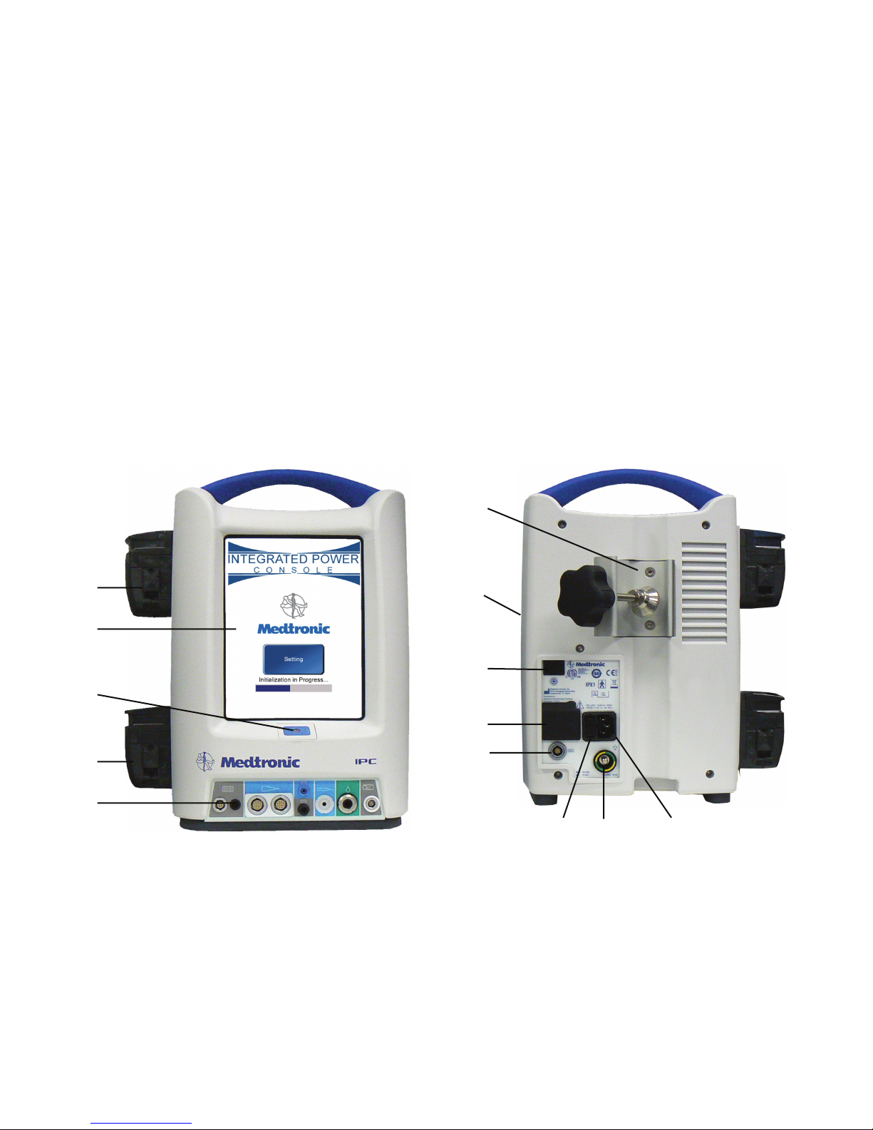
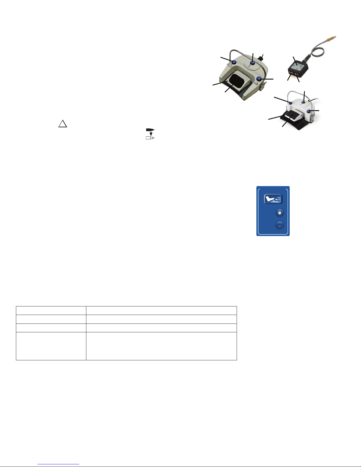
Figure 1-1. IPC Console Front
1
1
2
3
4
5
2
3
4
5
Figure 1-2. IPC Console Back
67 8
1 Pump 1: Coolant, lens cleaning or irrigation
2 Touchscreen
3 Power on/o
4 Pump 2: Irrigation or lens cleaning
5 Console connector panel for peripheral devices
1 Pole clamp
2 Compact ash card port (Medtronic Use)
3 Manual start/stop
4 Auxiliary power outlet
5 Endo-Scrub 2 connector
6 Fuse access
7 Equipotential Ground Connector.
Apply potential equalization conductor.
8 Hospital grade power cord connector
1-5
INTEGRATED POWER CONSOLE (IPC)
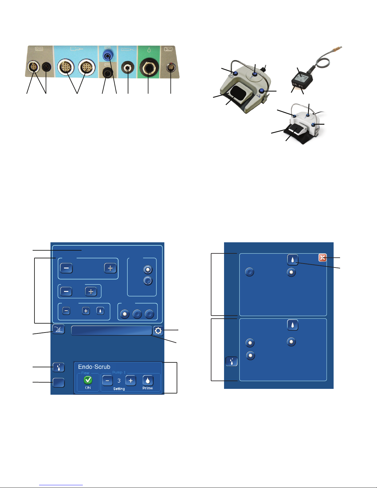
Figure 1-3. IPC Console Connector Panel
412 3567 8
1 Legend EHS motor 4 Stimulus input from patient
interface (NIM or NIM-ECLIPSE)
2 Legend EHS Stylus motor 5 Stimulus output to stim bur
guard or POWEREASE
3 Spine shaver handpiece,
6 Skeeter handpiece
StraightShot M5 microdebrider,
StraightShot M4 microdebrider,
StraightShot Magnum II
microdebrider, StraightShot
III microdebrider, Stylus Touch
motor, Visao drill, Indigo drill,
Midas Rex microsaws, Triton drill
7 Endo-Scrub 2 nger switch,
Endo-Scrub 2 foot pedal,
Intelliow irrigation remote
control
8 Multifunction foot pedal
Figure 1-4. Multifunction Foot Pedal & Y-Splitter
1
5
4
2
3
1
6
7
8
5
4
1 Mode button 5 Foot pedal
2 Handpiece button 6 Y-Splitter
3 Control button 7 Port 1
4 Slip-resistant foot pad 8 Port 2
2
3
Figure 1-5. IPC Touchscreen
1
Speed
2
3
4
5
Acceleration
Pump 2
Pumps
?
?
Help
Handpiece Name
60000
RPM
100
+
+
%
+
+
0
cc/min
Prime
(Handpiece Name)
EndoScrub 2
Flow
+
+
3
Setting
Control
Finger
+
+
Mode
FWD
REV
Foot
Both
PrimeOn
1 Displays active handpiece 5 Opens Help screen
2 Accessory control panel 6 Irrigation accessory panel
3 Foot pedal variable control 7 Inactive handpiece
4 Opens Pumps screen 8 Set active handpiece settings as
default settings
Figure 1-6. IPC Pumps Screen
Pump 1
None
None
Prime
Prime
Endo-Scrub® 2
Endo-Scrub® 2
1
2
3
8
7
6
4
Pump 2
None
None
M4
M4
Irrigation
Irrigation
Prime
Endo-Scrub® 2
Endo-Scrub® 2
1 Close Pumps screen 3 Pump 1 panel available
accessories
2 Prime/Flush pump 4 Pump 2 panel available
accessories
1-6
INTEGRATED POWER CONSOLE (IPC)
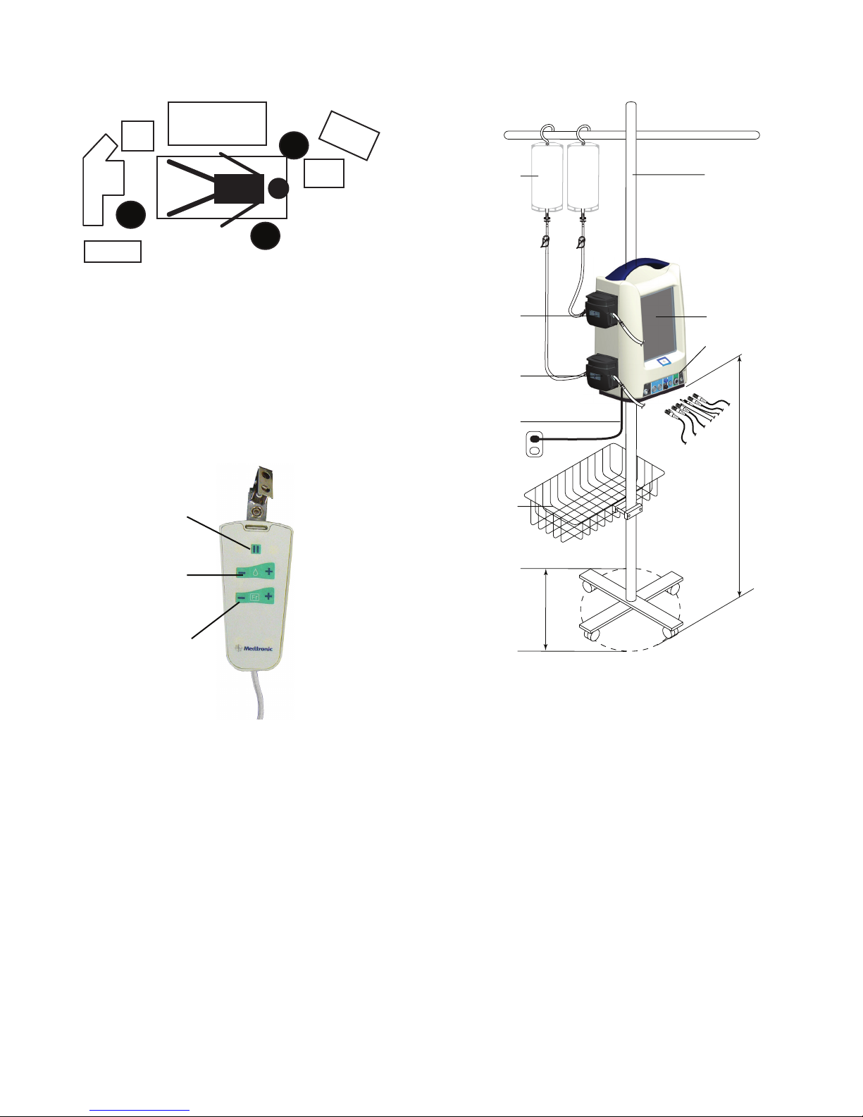
Figure 1-7. Operating Room Setup
3
2
1
10
4
6
9
7
8
1 Mode anesthesia equipment 6 Microscope
2 IPC system 7 Surgeon
3 Nursing supplies/Surgical
instruments
4 Scrub nurse 9 Anesthesiologist
5 NIM Monitor 10 Patient
Figure 1-9. IntelliFlow Remote Control
8 Electro-Surgical unit
Figure 1-8. IPC System Conguration
5
1
11
10
9
2
3
4
5
6
1
2
3
1 Pause/On-O
2 Increase/Decrease Fine Adjustment
3 Increase/Decrease Coarse Adjustment OR
Select stainless steel tubing size (French size) for
suction irrigator.
8
7
1 Irrigation and coolant bags 7 Irrigation pole base diameter
2 Irrigation pole 8 Irrigation pole basket
3 IPC console 9 Power cord
4 Console connector panel 10 Pump 2
5 Accessory cables 11 Pump 1
6 Console height
1-7
INTEGRATED POWER CONSOLE (IPC)
PREOPERATING INSTRUCTIONS
The following are general IPC pre-operating instructions. Refer to other sections of this IFU for operating instructions specic to individual
handpieces or accessories.
When the System Arrives
• Verify the contents of the box match the packing slip. If incomplete or damaged, notify Medtronic Customer Service.
• If container is damaged, or cushioning material shows stress, notify carrier and Medtronic Customer Service. Keep shipping materials for carrier
inspection.
• Save the cartons and packing material. If the instrument is to be shipped the shipping package will provide proper protection.
Set up the IPC
Refer the related topics for detailed instruction.
1. Install pump cartridges or irrigation tubing.
2. Prepare IPC for use.
3. Calibrate touchscreen, if necessary.
4. Change system settings, if necessary.
5. Set up and prime pumps.
6. Conrm system operation.
7. Press the manual start/stop button on the back of the console (Figure 1-2) and verify you can start/stop the handpiece, irrigation and/or
coolant ow.
Install the Pump Cartridges or Irrigation Tubing
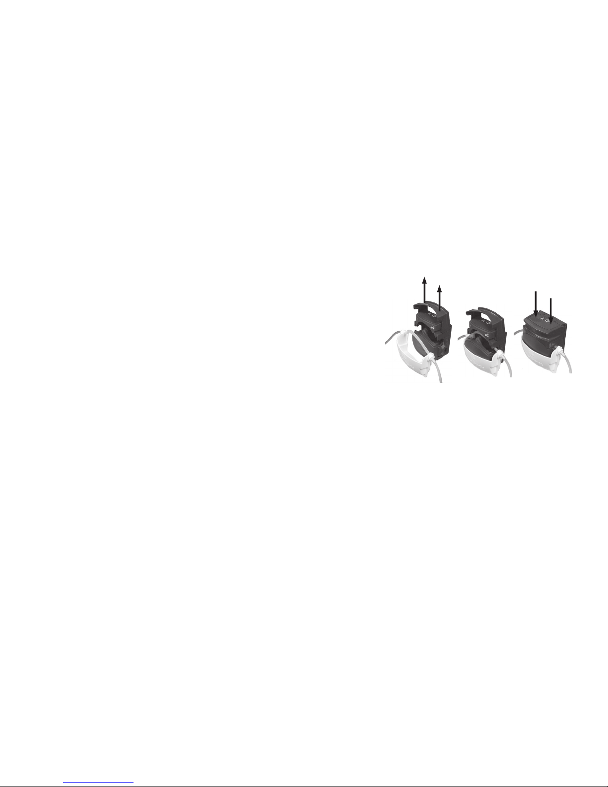
1. Locate the correct pump and lift up the lock (Figure 1-10).
Pump 1: Coolant, lens cleaning or irrigation
Pump 2: Irrigation
Important: The number on the pump must match the number on the cartridge (either
1/1 or 2/2). If the cartridge does not have a pump designator number, use the Pump
Setup Screen to install the pump cartridge.
2. Insert the pump cartridge.
3. Snap the pump lock shut.
Warning: Ensure the pump cartridge does not crimp the tubing.
Figure 1-10. Install Pump Cartridge
1
2
3
Prepare IPC for Use
1. Verify Operation Room set up (Figure 1-7). The surgeon may have preferences to the location and visibility.
2. Verify the wheels are locked on the IPC cart.
3. Inspect all components for damage and determine if the system is ready for use.
4. Mount the IPC and irrigation/coolant bags on the I.V. pole (Figure 1-8).
Important:
• Mount irrigant and coolant bags above the IPC to ensure adequate ow.
• It is recommended to use an irrigation pole with minimum base diameter of 53 cm and to mount all items as low as possible to
increase stability during use.
• For transport or uneven oor conditions greater than 10 degrees, maximum height to mount the console is 38 cm if irrigation and
coolant bags are at fully extended pole height.
5. Plug the IPC into the power source. Position the IPC so that it does not obstruct the power source for the purpose of disconnecting the Main
voltage by the power cord.
6. Locate the correct foot pedal or accessory connection port on the connector panel (Figure 1-3), align the mark on the connector to the mark
on the console, and then insert the connector.
7. Connect suction, cooling and/or irrigation tubing.
8. Turn on the IPC and verify the system passes the self-test.
Note: If the IPC does not detect a handpiece or foot pedal the Connect Handpiece/Connect Foot Switch screen appears. Do the following:
• Verify the cable is connected to the correct connection port.
• Press [OK] in the Connect Handpiece/Connect Foot Switch message window to continue use of the IPC without the handpiece or foot
pedal.
Calibrate Touchscreen
Note: This step is optional.
1. Turn on the IPC console.
2. When the system starts, on the Splash screen, press [Settings].
3. On the Settings screen, press Touch Screen Calibration and follow the screen prompts.
1-8

INTEGRATED POWER CONSOLE (IPC)
Change System Settings
Note: During surgery, system settings can be overwritten.
1. Turn on the IPC console.
2. While the system starts, on the Splash screen, press [Settings].
3. To change the language, press the appropriate language.
4. To change the default settings, press [Default].
• On the Default screen, press the Forward or Backward arrow to change the accessory.
• Make changes to the default settings.
• To conrm system settings and return to the Splash screen, press [OK].
5. For accessories with audible tones, press the REV Audible Tones button to control the following:
• The system delivers one set of reverse beeps when the Reverse mode is activated.
• The system delivers one set of reverse beeps the rst time the drill is used in Reverse mode after the Reverse mode has been activated.
6. To conrm system settings and continue to the IPC touchscreen, press [OK].
7. To restore settings to factory default, press [Restore].
Handpiece Default Settings
The system conguration is dependent on the handpiece(s) connected to the console. The following table denes the default congurations,
default settings (X) and default options (O).
Note: During use, update the default settings for the active handpiece by pressing the set active handpiece settings as default settings button
(Figure 1-5).
Table 1. IPC Touchscreen Default Congurations
Speed Mode or Mode Select Switch
Handpiece rpm cpm % Forward Oscillate Reverse Acceleration Deceleration Size Flow Irrigation Control
Visao 80000 X O 30
Indigo 52000 X O 30
Midas Rex SC1 3400 O X 60
StraightShot M5 5000 O X 05
StraightShot M4 5000 O X 05
StraightShot III, Magnum II 5000 O X 30
Legend EHS Stylus 60000 X O 45 % 45 % 0
Legend EHS 70000 X O 0
Stylus Touch 60000 X O 80 % 100 % 0 Finger
Skeeter 16000 X O v 0
Endo-Scrub 2 3
Suction Irrigator 8 50 %
Triton 100 X
100 X
Midas Rex Microsaws 100 0
POWEREASE 120 X
120 X
250 X
1-9

INTEGRATED POWER CONSOLE (IPC)
+
Set up and Prime Pumps
• The IPC turns on pump 1 and/or 2 long enough to purge air out of the tubing set(s) the rst time the prime button is pressed.
• The IPC resets the prime feature when you turn IPC power O and On.
• After you prime the pump, the prime button and functionality become ush functionality.
1. Connect tubing from an IPC cartridge to irrigation or coolant tubing on an accessory.
2. On the irrigation tubing, turn the clamp to OPEN.
3. If an accessory uses the clear drip chamber (Visao), ll the clear drip chamber with coolant. To ll, squeeze and release the chamber until full.
4. On the IPC touchscreen (Figure 1-5), press the pumps button.
Note: The IPC pumps screen is also available from the Connect Handpiece/Connect Foot Switch screen which the system displays during
IPC preparation for use if a handpiece or foot switch is not detected by the system.
5. On the IPC pumps screen (Figure 1-6), select the accessory for each pump.
6. For each pump, press the prime button and verify the following:
• Pump(s) run until air is completely purged from tubing.
• Small amount of lubricant ows at the tip of the irrigation device.
• Pump(s) turns o.
7. Press the close button.
Pump Default Congurations
The pump conguration is dependent on the handpiece(s) connected to the console. The following table denes the pump default settings (X) and
default options (O).
Table 2. IPC Pumps Screen Default Congurations
Pump 1 Pump 2 Endo-Scrub 2 Suction Irrigator
Handpiece Cooling Irrigation Irrigation Pump 1 Pump 2 Pump 1 Pump 2
Visao X X O O
Indigo O X O O O O
Midas Rex SC1 O X O O
StraightShot M5 O X* X O
StraightShot M4 O X* X O
StraightShot III, Magum II O X* X O
Legend EHS Stylus X O* O O O O
Legend EHS X O O O O O
Stylus Touch X O O O O O
Skeeter O O O O
Endo-Scrub 2 X O X O
Suction Irrigator O O O O
Midas Rex Microsaws O X O O O O
POWEREASE O O O O
* When the IPC detects both the StraightShot M4 or StraightShot M5 and the Legend EHS Stylus Touch handpiece, by default, the system sets
pump 2 as a “shared” irrigation pump. You must manually connect the irrigation tubing to the active handpiece.
Conrm System Operation
1. Conrm the irrigation pedal starts handpiece and irrigation ow. Verify the speed changes from white to yellow in the Speed box on the
touchscreen.
2. Conrm the foot pedal buttons operate. Refer to “Multifunction Foot Pedal” for details.
3. On the touchscreen, verify you can do all of the following:
• Adjust Speed: In the Speed box, press the plus and minus buttons.
• Change Modes: In a Mode box, press any mode button.
• Adjust Flow Rate: In the Irrigation box, press the plus and minus buttons.
1-10
+
+
+

INTEGRATED POWER CONSOLE (IPC)
IPC COMPONENTS
Auxillary Power to Console
Warning: The auxillary power outlet is available for use with the Hydrodebrider and Bone Mill IPC consoles only (see W82).
The auxillary power outlet is for use at grid voltage ≤120 VAC only.
Multifunction Foot Pedal
You can use the multifunction foot pedal (Figure 1-4) to start/stop the handpiece, control handpiece speed, handpiece selection and mode of
operation. Refer to the Multifunction Foot Pedal Controls topic for each handpiece for specic use and control.
Y-Splitter
Y-Splitter (Figure 1-4) allows using a maximum of two multifunction foot pedals connected to a single IPC (see P23 & P24). In this conguration,
the Y-Splitter shall be connected to the IPC, and the Multifunction Foot Pedal(s) shall be connected to the Y-Splitter. When connecting a single foot
pedal to the Y-Splitter, you may connect to either Port 1 or 2.
IntelliFlow Irrigation Remote Control
Use the IntelliFlow irrigation remote control (Figure 1-9) to start/stop and change irrigation ow while in the sterile eld.
If you are using handpiece irrigation:
• To pause irrigation ow, press the Pause/On-O button.
• To adjust ow rate, press the Fine Adjustment or Coarse Adjustment Increase/Decrease button.
If you are using the Suction Irrigator:
• To pause or turn on/o the Suction Irrigator, press the Pause/On-O button.
• To adjust ow rate, press the Fine Adjustment Increase/Decrease button.
• To select the stainless steel tubing size (French size), press the Stainless Steel Tubing Size button.
1-11

INTEGRATED POWER CONSOLE (IPC)
GUIDANCE AND MANUFACTURER’S DECLARATION ELECTROMAGNETIC IMMUNITY
Part I
The IPC is intended for use in the electromagnetic environment specied below. The customer or the user of the IPC should assure that it is used in such an
Immunity test
Electrostatic discharge (ESD) ±6kV contact ±6kV contact
IEC 61000-4-2 ±8kV air ±8kV air
Electrical fast transient/burst
IEC 61000-4-4
Surge
IEC 61000-4-5
Voltage dips, short interruptions and voltage variations on
power supply input lines
IEC 61000-4-11
Power frequency (50/60 Hz)
magnetic eld
IEC 61000-4-8
Note: UT is the a.c. mains voltage prior to application of the test level.
The IPC is intended for use in the electromagnetic environment specied below. The customer or the user of the IPC should assure that it is used in such an
Emissions test Compliance Electromagnetic environment - guidance
RF emissions
CISPR 11
RF emissions
CISPR 11
Harmonic emissions
IEC 61000-3-2
Voltage uctuations
IEC 61000-3-3
IEC/EN60601-1-2
test level
±2kV for power supply lines
±1kV for input/output lines
±1kV dierential mode
±2 kV common mode
<5 % UT (>95 % dip in UT)
for 0.5 cycle
40 % UT (60 % dip in UT) for
5 cycles
70 %UT (30 % dip in UT) for
25 cycles
<5 % UT (>95 % dip in UT)
for 5 sec
3 A/m 3 A/m
Guidance and manufacturer’s declaration – electromagnetic emissions
Group 1
Class A
Class A
Complies
±2kV for power supply lines
±1kV for input/output lines
±1kV dierential mode
±2kV common mode
<5 % UT (>95 % dip in UT)
for 0.5 cycle
40 % UT (60 % dip in UT) for
5 cycles
70 % UT (30 % dip in UT) for
25 cycles
<5 % UT (>95 % dip in UT)
for 5 sec
environment.
Compliance level Electromagnetic environment - guidance
Floors should be wood, concrete, or ceramic tile. If oors are covered
with synthetic material, the relative humidity should be at least 30 %.
Mains power quality should be that of a typical commercial or hospital
environment.
Mains power quality should be that of a typical commercial or hospital
environment.
Mains power quality should be that of a typical commercial or hospital
environment. If the user of the IPC requires continuous operation during
power mains interruptions, it is recommended that the IPC be powered
from an uninterruptible power supply or a battery.
Power frequency magnetic elds should be at levels characteristic of a
typical location in a typical commercial or hospital environment.
environment.
The IPC uses RF energy only for its internal function. Therefore, its RF emissions are very low
and are not likely to cause any interference in nearby electronic equipment.
The IPC is suitable for use in all establishments, other than domestic and those directly
connected to the public low-voltage power supply network that supplies buildings for
domestic purpose.
Recommended separation distances between portable and mobile RF communications equipment and the IPC
The IPC is intended for use in the electromagnetic environment in which radiated RF disturbances are controlled. The customer or the user of the IPC can help
prevent electromagnetic interference by maintaining a minimum distance between portable and mobile RF communications equipment (transmitters) and the IPC
as recommended below, according to the maximum output power of the communications equipment.
Rated maximum power
of transmitter
W
0.01 0.12 0.12 0.23
0.10 0.38 0.38 0.73
1.00 1.20 1.20 2.30
10.00 3.80 3.80 7.30
100.00 12.00 12.00 23.0
For transmitters rated at a maximum output power not listed above, the recommended separation distance d in meters (m) can be estimated using the equation
applicable to the frequency of the transmitter, where P is the maximum output power rating of the transmitter in watts (W) according to the transmitter
manufacturer.
NOTE 1 At 80 MHz and 800 MHz, the separation distance for the higher frequency range applies.
NOTE 2 These guidelines may not apply in all situations. Electromagnetic propagation is aected by absorption and reection from structures, objects and
people.
150 kHz to 80 MHz
d = 1.2√P
Separation distance according to frequency of transmitter meters
80 MHz to 800 MHz
d = 1.2√P
800 MHz to 2.5 GHz
d = 2.3√P
1-12

Part II
The IPC is intended for use in the electromagnetic environment specied below.
The customer or the user of the IPC should assure that it is used in such an environment.
Immunity test IEC/EN60601-1-2 test
level
Conducted RF 3Vrms 3Vrms d = 1.2√P
IEC 61000-4-6 150kHz to 80MHz
Radiated RF 3V / m 3V / m d = 1.2√P 80MHz to 800MHz
IEC 61000-4-3 80MHz to 2.5GHz d = 2.3√P 800MHz to 2.5GHz
Compliance level Electromagnetic environment - guidance
Portable and mobile RF communications equipment should be used no closer to
any part of the IPC , including cables, than the recommended separation distance
calculated from the equation applicable to the frequency of the transmitter.
Recommended separation distance
Where P is the maximum output power rating of the transmitter in watts (W)
according to the transmitter manufacturer and d is the recommended separation
distance in meters (m).
Field strengths from xed RF transmitters, as determined by an electromagnetic site
survey a, should be less than the compliance level in each frequency rangeb.
Interference may occur in the vicinity of equipment marked with the following
symbol:
INTEGRATED POWER CONSOLE (IPC)
NOTE 1 At 80 MHz and 800 MHz, the higher frequency range applies.
NOTE 2 These guidelines may not apply in all situations. Electromagnetic propagation is aected by absorption and reection from structures, objects and people.
NOTE 3 When operating the IPC with Stylus Touch, the compliance level is 3 V/m except from 88 MHz to 91 MHz where it is 1 V/m. The formula for separation
distance for the IPC with Stylus Touch will be d = 3.5 √P in that frequency range.
a
Field strengths from xed transmitters, such as base stations for radio (cellular/cordless) telephones and land mobile radios, amateur radio, AM and FM radio
broadcast and TV broadcast cannot be predicted theoretically with accuracy. To assess the electromagnetic environment due to xed RF transmitters, an
electromagnetic site survey should be considered. If the measured eld strength in the location in which the IPC is used exceeds the applicable RF compliance
level above, the IPC should be observed to verify normal operation. If abnormal performance is observed, additional measures may be necessary, such as reorienting or relocating the IPC .
b
Over the frequency range 150 kHz to 80 MHz, eld strengths should be less than 3 V/m.
1-13

INTEGRATED POWER CONSOLE (IPC)
LIMITED WARRANTY
A. This Limited Warranty provides the following assurance for the customer who purchases a Medtronic IPC System. This Limited Warranty is extended
only to the buyer purchasing the IPC System directly from Medtronic or from its aliate or its authorized distributor or representative. The IPC
System includes the console, motor or handpiece, foot control, motor cables, instrumentation cases and trays (hereafter referred to as System
Components), straight and angled motor attachments (hereinafter referred to as “Attachments”), bur guards and telescoping tubes (hereinafter
referred to as Semi-reusable Components) and dissecting tools, irrigation and coolant tubing, and Intelliow remote control (hereinafter referred
to as Single Use Components) and jointly referred to as the IPC System, unless specically noted.
i. Should a System Component fail to function to Medtronic’s published specications during the term of this Limited Warranty (one [1] year
from the date of sale of a new System Component or ninety [90] days from the date of sale of a refurbished or used System Component),
Medtronic will either repair or replace the Motor Component or any portion thereof.
ii. Should an Attachment fail to function to Medtronic’s published specications during the term of this Limited Warranty (ninety [90] days from
the date of sale of a new Attachment), Medtronic will either repair or replace the Attachment or any portion thereof.
iii. Should a Semi-reusable Component fail to function to Medtronic’s published specications during the term of this Limited Warranty (thirty
[30] days from the date of sale of a new Semi-reusable Component), Medtronic will replace the Semi-reusable Component or any portion
thereof.
iv. Should a Single Use Component fail to function to Medtronic’s published specications prior to its “use by” date Medtronic will replace the
Single Use Component.
B. To qualify for this Limited Warranty, the following conditions must be met:
i. The Product must be used on or before its “Use By” or “Use Before” date, if applicable.
ii. The Product must be used in accordance with its labeling and may not be altered or subjected to misuse, abuse, accident or improper
handling.
iii. Medtronic must be notied in writing within thirty (30) days following discovery of a defect.
iv. The Product must be returned to Medtronic within thirty (30) days of Medtronic receiving notice as provided for in (3) above.
v. Upon examination of the Product by Medtronic, Medtronic shall have determined that: (i) the Product was not repaired or altered by anyone
other than Medtronic or its authorized representative, (ii) the Product was not operated under conditions other than normal use, and (iii) the
prescribed periodic maintenance and services, if applicable, have been performed on the Product.
C. This Limited Warranty is limited to its express terms. THIS LIMITED WARRANTY IS IN LIEU OF ALL OTHER WARRANTIES, EXPRESSED OR IMPLIED
WHETHER STATUTORY OR OTHERWISE, INCLUDING ANY IMPLIED WARRANTY OF MERCHANTABILITY OR FITNESS FOR A PARTICULAR PURPOSE.
In no event shall Medtronic be liable for any consequential, incidental, prospective or other similar damage resulting from a defect, failure, or
malfunction of the IPC System, whether a claim for such damage is based upon the warranty, contract, negligence or otherwise.
D. The exclusions and limitations set out above are not intended to, and should not be construed so as to, contravene mandatory provisions of
applicable law. Users may benet from statutory warranty rights under legislation governing the sale of consumer goods. If any part or term of
this Limited Warranty is held by any court of competent jurisdiction to be illegal, unenforceable, or in conict with applicable law, the validity
of the remaining portion of the Limited Warranty shall not be aected, and all rights and obligations shall be construed and enforced as if this
Limited Warranty did not contain the particular part or term held to be invalid.
FOR ITEMS CONTAMINATED WITH TSE AGENTS
Medtronic ENT/NT Transmissible Spongiform Encephalopathy (TSE) Return Policy
Medtronic will not authorize or accept the return of products that directly contact patients or is contaminated with a patient’s body uids
suspected or conrmed with a Transmissible Spongiform Encephalopathy / Creutzfeldt-Jakob Disease (TSE/CJD) diagnosis.
The following are recommended guidelines and may vary according to specic policy and procedures among hospitals. Hospital personnel should
contact their infection control personnel for current procedures and policy for reusable equipment processing when suspected of contamination
with Creutzfeldt-Jakob Disease (CJD) or other Transmissible Spongiform Encephalopathy (TSE) agent.
Medtronic dissecting tools, burs, or blades used on a patient suspected of a TSE/CJD diagnosis should be incinerated. Reusable equipment that
has been used on patients with suspected Creutzfeldt-Jakob Disease (CJD) or other Transmissible Spongiform Encephalopathy (TSE) should be
quarantined and not reused until diagnosis is conrmed or excluded. Reusable equipment should be quarantined after having been cleaned,
decontaminated, sterilized and packed in a rigid sealed container until nal diagnosis. If TSE/CJD is excluded as a diagnosis, the quarantined
reusable equipment may be returned for use after appropriate cleaning, decontamination and sterilization.
Medtronic recommends that all Medtronic products used directly on a patient conrmed with a TSE diagnosis be incinerated. Contact your Sales
Representative to purchase replacement products or secure loaner equipment.
For additional information contact your Customer Service Representative.
1-14
TRITON ELECTRIC HIGH-TORQUE HANDPIECE
TRITON ELECTRIC HIGHTORQUE HANDPIECE
DEVICE DESCRIPTION
The Triton Electric High-Torque Handpiece is capable of removing hard and soft tissue, drilling pilot holes, and driving screws, wires, and pins
during spinal, cranial, and small-bone surgical procedures performed in an operating-room environment by surgeons trained in its use.
The following instructions for the Triton Electric High-Torque Handpiece are in addition to “Set up the IPC” general assembly instructions. Complete
IPC setup, then continue to the instructions below.
BEFORE USE
Clean and sterilize the device, prior to rst use. Refer to the Reprocessing Instructions contained in this manual for additional information.
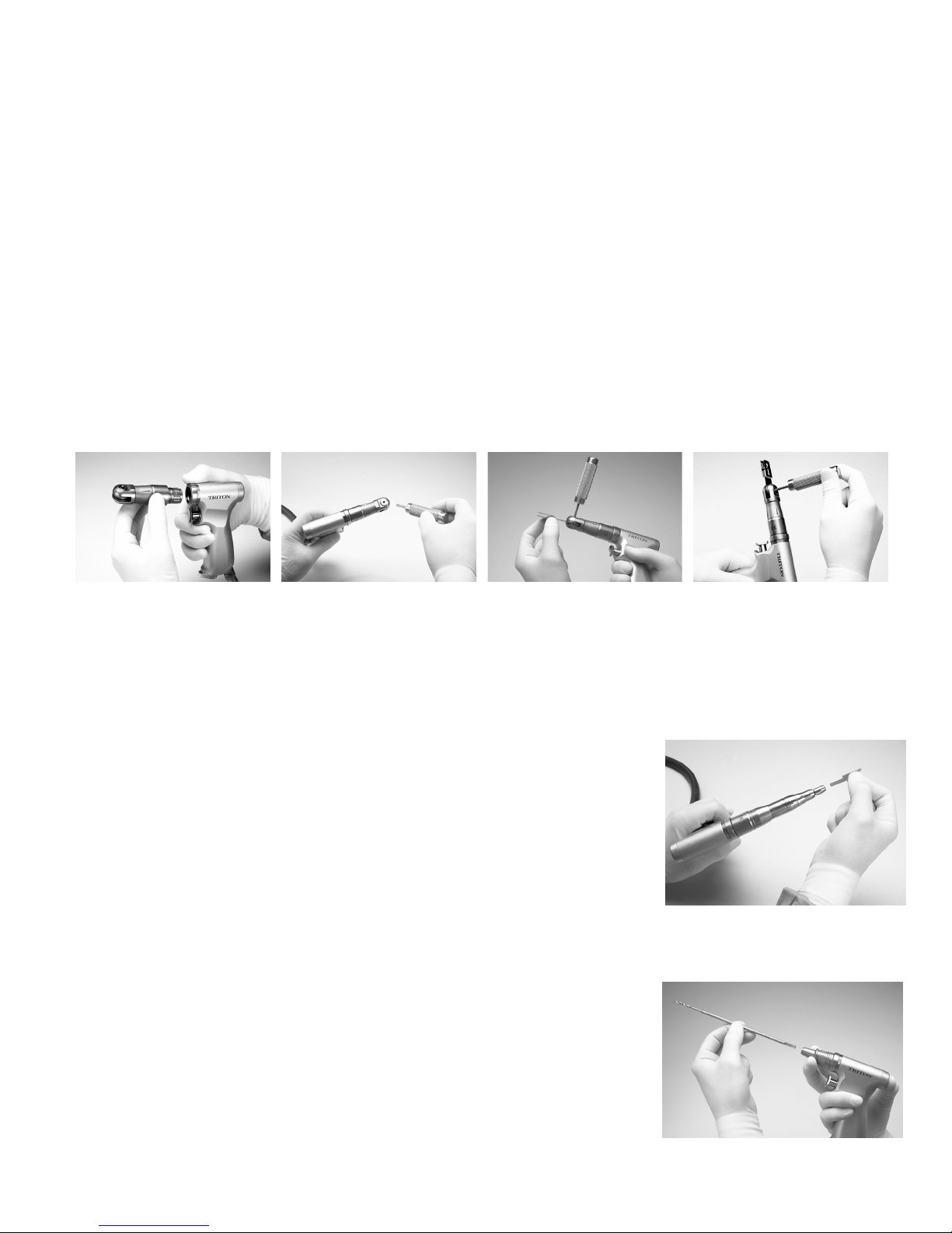
TRITON SAGITTAL SAW ASSEMBLY
Warning: Triton saw attachments should only be used with Medtronic Triton saw blades. Refer to the Triton Quick Reference Saw Blade Guide
(LIT200017) for additional information on Triton saw blades.
1. Insert the Sagittal Saw Attachment into the hand piece in a position to allow easy in ser tion of the Sagittal Saw Key (Figure 2-1).
Note: You can install the attachment in 12 di er ent po si tions to facilitate proper surgical ac cess.
2. Insert the Sagittal Saw Key into the attachment and turn coun ter clock wise until there is slight re sis tance.
3. Insert the blade into the space between the two jaws, ensuring that the blade is fully seated.
4. Turn the Sagittal Saw Key clockwise to lock the blade. Run briey, then retighten blade.
Caution: Do not over-tighten.
Figure 2-1. Sagittal Saw Assembly
TRITON SAGITTAL SAW DISASSEMBLY
To remove the Triton saw blade, insert the Sagittal Saw Key into the Attachment and turn coun ter clock wise.
TRITON RECIPROCATING SAW ASSEMBLY
Warning: Triton saw attachments should only be used with Medtronic Triton saw blades. Refer to the
Triton Quick Reference Saw Blade Guide (LIT200017) for additional information on Triton saw blades.
1. Loosen the collet nut then insert the blade until it is ful ly seat ed (Figure 2-2).
Note: You can install the attachment in di er ent po si tions to facilitate proper surgical ac cess.
2. Finger-tighten the collet nut. Run briey, then retighten collet nut.
TRITON RECIPROCATING SAW DISASSEMBLY
To remove the Triton Reciprocating Saw blade, unscrew the collet nut.
TRITON AO/SYNTHES CHUCK AND TRINKLE CHUCK ASSEMBLY
1. To install a drill bit, pull back on the attachment collar (Figure 2-3).
2. Insert the drill bit and release the attachment collar.
TRITON AO/SYNTHES CHUCK AND TRINKLE CHUCK DISASSEMBLY
1. To remove a drill bit, pull back on the attachment collar.
2. Remove the drill bit and release the attachment collar.
Figure 2-2. Reciprocating Saw Assembly
Figure 2-3. AO/Synthes Chuck and Trinkle
Chuck Assembly
2-1
TRITON ELECTRIC HIGH-TORQUE HANDPIECE
TRITON JACOBS CHUCK ASSEMBLY
1. To install a drill bit, turn the key to open the chuck or spin the collar if using a keyless chuck
attachment (Figure 2-4).
2. Insert the drill bit.
TRITON JACOBS CHUCK DISASSEMBLY
1. To remove a drill bit, turn the key to open the chuck or spin the collar if using a keyless chuck
attachment.
2. Remove the drill bit.
TRITON HUDSON AND ZIMMER CHUCK ASSEMBLY
To install an instrument, pull back on the attachment collar, then insert the male end of the instrument
into the chuck (Figure 2-5).
TRITON HUDSON AND ZIMMER CHUCK DISASSEMBLY
To remove an instrument, pull back on the attachment collar, then remove the instrument from the
chuck.
Figure 2-4. Jacobs Chuck Assembly
Figure 2-5. Hudson and Zimmer Chuck
Assembly
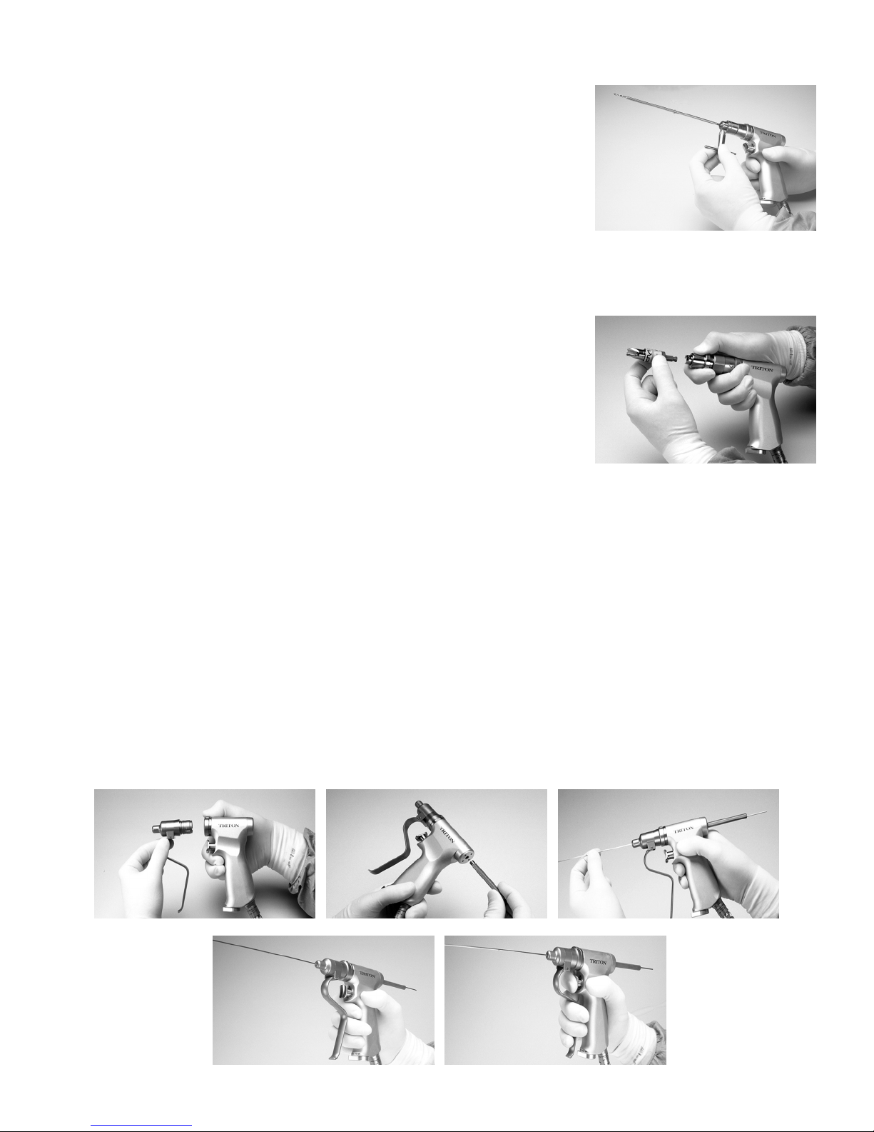
TRITON WIRE AND PIN COLLET ASSEMBLY
The Wire Collet accepts wires up to 1.6 mm (.062 inches) in diameter. The Pin Collet accepts pins up to 3.2 mm (.125 inches) in di am e ter.
1. Insert the Wire or Pin Collet (Figure 2-6) while the handpiece is in the SAFE position (Figure 2-7).
2. Screw the Cannulated Extension in the back of the handpiece to protect the op er a tor from the point of the wire or pin, as necessary.
3. Insert the wire or pin into the front or back of the handpiece.
4. Put the instrument in the RUN position by po si tion ing the trigger control vertically.
5. Turn the Mode select switch at the base of the handle to the FORWARD position.
6. Squeeze the Wire/Pin Advance lever and hold it down.
7. Press the trigger control to drive the wire/pin. The pressure-sensitive trigger allows vari able speed operation.
8. To obtain additional wire/pin length, release the wire/pin.
9. Advance the lever and trigger control.
10. Pull back on the in stru ment.
11. Squeeze the Wire/Pin Advance lever and trigger control to drive the wire.
TRITON WIRE AND PIN COLLET DISASSEMBLY
To remove threaded wire/pin, put the Mode select switch in REVERSE, squeeze the Wire/Pin Advance lever and press the trigger control.
Figure 2-6. Wire and Pin Collet Assembly
2-2
TRITON ELECTRIC HIGH-TORQUE HANDPIECE
12
%
TRITON ELECTRIC HIGHTORQUE HANDPIECE OPERATION
You can preload attachments before insertion into the handpiece.
Caution: Insert all attachments into the handpiece with the handpiece in the SAFE po si tion (Figure 2-7).
Note: The handpiece has an Extension Handle that screws into the back of the handpiece. The handle extension provides bal ance and two-hand ed
con trol for various drilling and cutting applications.
1. With the handpiece in the SAFE position (Figure 2-7), insert a preloaded attachment by pressing the quick-release button on top of the
handpiece. Snap the attachment into the handpiece with a slight twisting motion un til it is seated.
2. Place the handpiece in the RUN position, with the trigger control vertical. The Mode select switch at the base of the handle should be in the
FORWARD position.
3. After use, return the trigger control to the SAFE position prior to removing the attachment.
4. Remove the attachment by pressing the quick-release but ton on top of the handpiece.
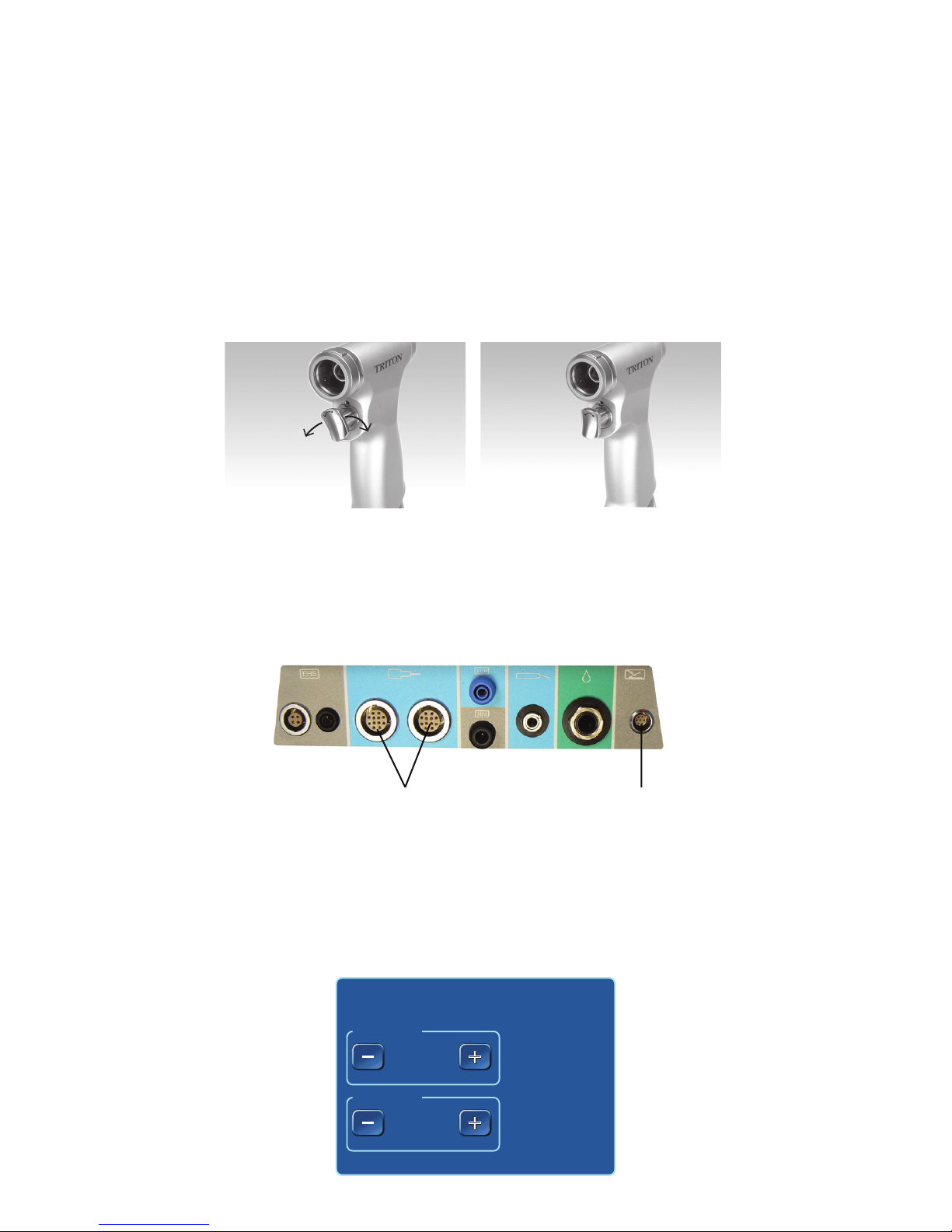
Safe Position
The handpiece will not op er ate in the SAFE position. To operate the handpiece, activate and press the trigger control.
Figure 2-7. Triton Handpiece Safe and Run positions
L
M
L
M
L
L
SAFE: Turn trigger control to either side to lock
handpiece in SAFE mode.
RUN: Trigger control in the vertical position will
allow activation of the handpiece.
CONNECT TRITON ELECTRIC HIGHTORQUE HANDPIECE TO IPC
Locate the Triton Electric High-Torque Handpiece connection port on the connector panel (Figure 2-8) and insert the connector.
Note: To insert multi-pin connectors (indicated by a silver or red mark on the connector), align the mark on the connector to the mark on the
console, then insert the connector.
Figure 2-8. Triton IPC Connection Ports
1 Triton handpiece connection port
2 Multifunction foot pedal connection port
TRITON ELECTRIC HIGHTORQUE HANDPIECE TOUCHSCREEN CONTROLS
To adjust Triton Electric High-Torque Handpiece variable speed, on the IPC touchscreen, in the FWD Speed or REV Speed control box (Figure 2-9),
press the plus button to increase variable speed or the minus button to decrease variable speed.
Figure 2-9. Triton Touchscreen
FWD Speed
FWD Speed
REV Speed
REV Speed
100
100
%
%
TRITON
TRITON
+
+
+
+
+
+
+
+
2-3
TRITON ELECTRIC HIGH-TORQUE HANDPIECE
TRITON ELECTRIC HIGHTORQUE HANDPIECE MODE
SELECT SWITCH
Use the mode select switch to change the handpiece from Forward to Reverse
when the handpiece is the active handpiece. When the handpiece is the inactive
handpiece, use the mode select switch to activate the handpiece.
TRITON ELECTRIC HIGHTORQUE HANDPIECE
MULTIFUNCTION FOOT PEDAL CONTROLS
Important: By default, press each button on the foot pedal for at least 100 mS for the
selection to become active. Use the IPC touchscreen Settings screen to change the
default value.
To use the multifunction foot pedal (Figure 2-10) to control the handpiece to do the
following:
• To toggle between the start/stop mode and variable speed mode, press the
control button.
• To change the handpiece, press the handpiece button.
Triton Electric High-Torque Handpiece Reverse Foot Pedal Control
When you connect the optional foot pedal to the IPC console, the pedal can be used
as an alternative method of activating Reverse mode (without manipulating the
Mode select switch at the bottom of the handpiece). When the pedal is connected,
the Reverse Pedal control box appears on the screen (Figure 2-11).
Note: By default, pedal functionality is turned OFF.
1. To use the pedal, press ON in the Reverse Pedal control box on the IPC touch
screen.
2. With the pedal turned on, step on the foot pedal to put the handpiece into
Reverse mode (regardless of what position the Mode select switch is in).
NOTE: The trigger control must be pressed to activate the handpiece, even
when you are stepping on the foot pedal.
3. Remove your foot from the pedal to return the handpiece to the mode
currently dened by the Mode select switch on the handpiece.
Figure 2-10. Multifunction Foot Pedal & Y-Splitter
1
5
4
1 Mode button 5 Foot pedal
2 Handpiece button 6 Y-Splitter
3 Control button 7 Port 1
4 Slip-resistant food pad 8 Port 2
Figure 2-11. Reverse Pedal Control Box
2
5
Reverse Pedal
Reverse Pedal
ON
ON
OFF
OFF
3
1
6
7
8
2
4
REV
REV
3
TRITON ELECTRIC HIGHTORQUE HANDPIECE CLEANING AND STERILIZATION INSTRUCTIONS
Refer to document M000030A322 in the Cleaning and Sterilization section.
TRITON ELECTRIC HIGHTORQUE HANDPIECE TECHNICAL SPECIFICATIONS
Triton Electric High-Torque Handpiece ED500
Size 3.5 inches Length x 5.4 inches Height x 1.1 inches Width
Weight 2.1 lbs
Speed 180-1800 rpm (actual speed depends on attachment used)
Duty Cycle for Applied Part Cycle Time: 20 seconds on maximum / 20 seconds o minimum
Maximum number of cycles before resting handpiece: 6
Maximum number of cycles before resting attachment: 3
Minimum rest period: 25 minutes
2-4
SUCTION IRRIGATOR
SUCTION IRRIGATOR
The following instructions for the Suction Irrigator are in addition to “Set up the IPC” general assembly instructions. Complete IPC setup, then
continue to the instructions below.
SUCTION IRRIGATOR ASSEMBLY
1. Connect the suction tubing from a suction source to the suction tting on the Suction Irrigator (Figure 3-1).
2. On the IPC touchscreen (Figure 1-5), press the pumps button.
3. On the IPC pumps screen (Figure 1-6), select a pump for the Suction Irrigator.
Note: When using a handpiece that connects to a pump, the IPC automatically incorporates the Suction Irrigator at the pump not in use by
the handpiece.
4. Connect the irrigation tubing from the IPC cartridge (Figure 1-8) to the irrigation tting on the Suction Irrigator (Figure 3-1).
5. On the irrigation tubing, turn the clamp to OPEN.
SUCTION IRRIGATOR ADAPTER KIT
1. Connect an adapter to the high-speed irrigation tubing (blue adapter) or the IPC tubing (white adapter).
2. Connect an adapter to the irrigation connector tube (Figure 3-2).
3. Connect an irrigation connector tube to the irrigation tting on the Suction Irrigator.
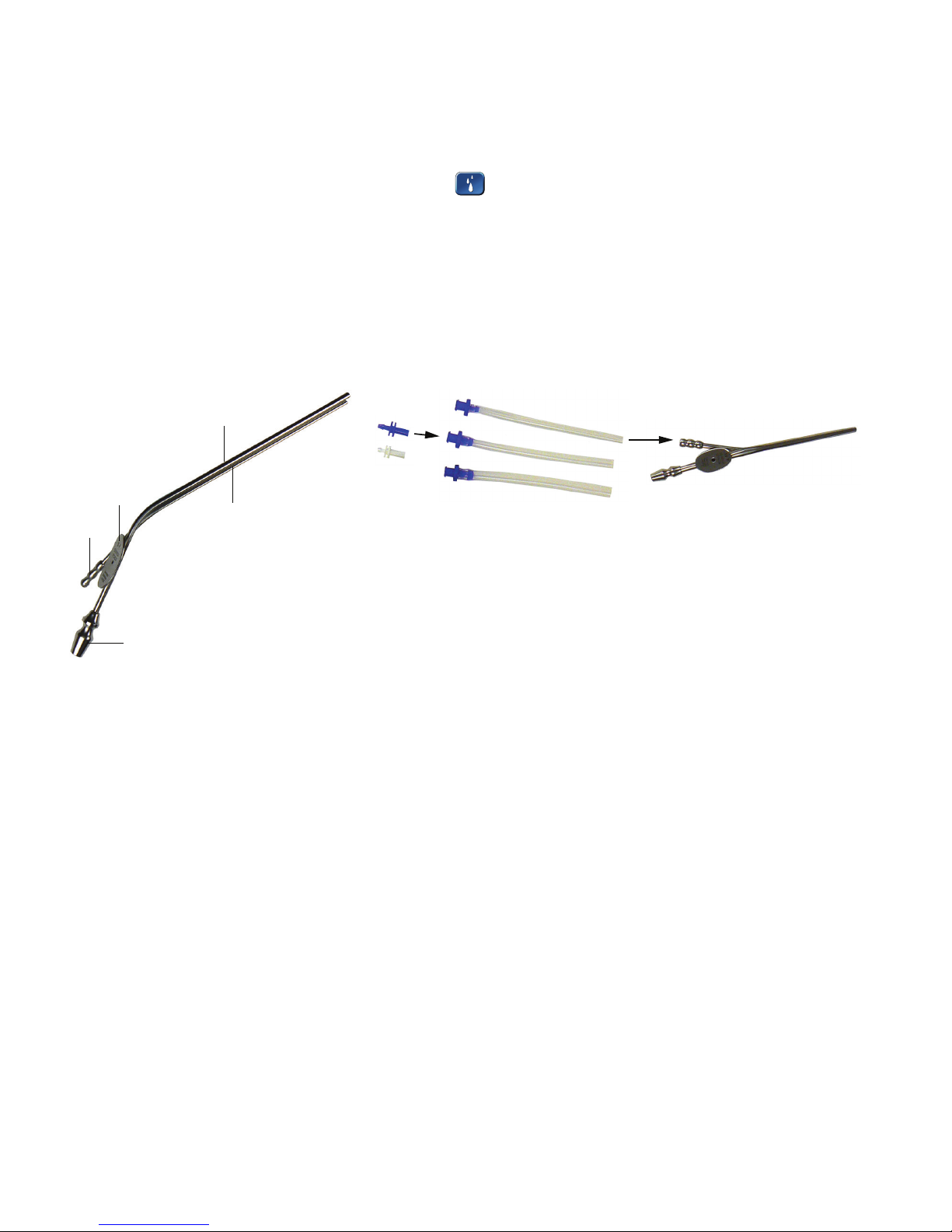
Figure 3-1. Suction Irrigator Figure 3-2. Suction Irrigator Adapter Kit
(1)
(3)
(4)
(5)
1 Suction tube 4 Irrigation tting
2 Irrigation tube 5 Suction tting
3 Tube size
(2)
3-1
SUCTION IRRIGATOR
+
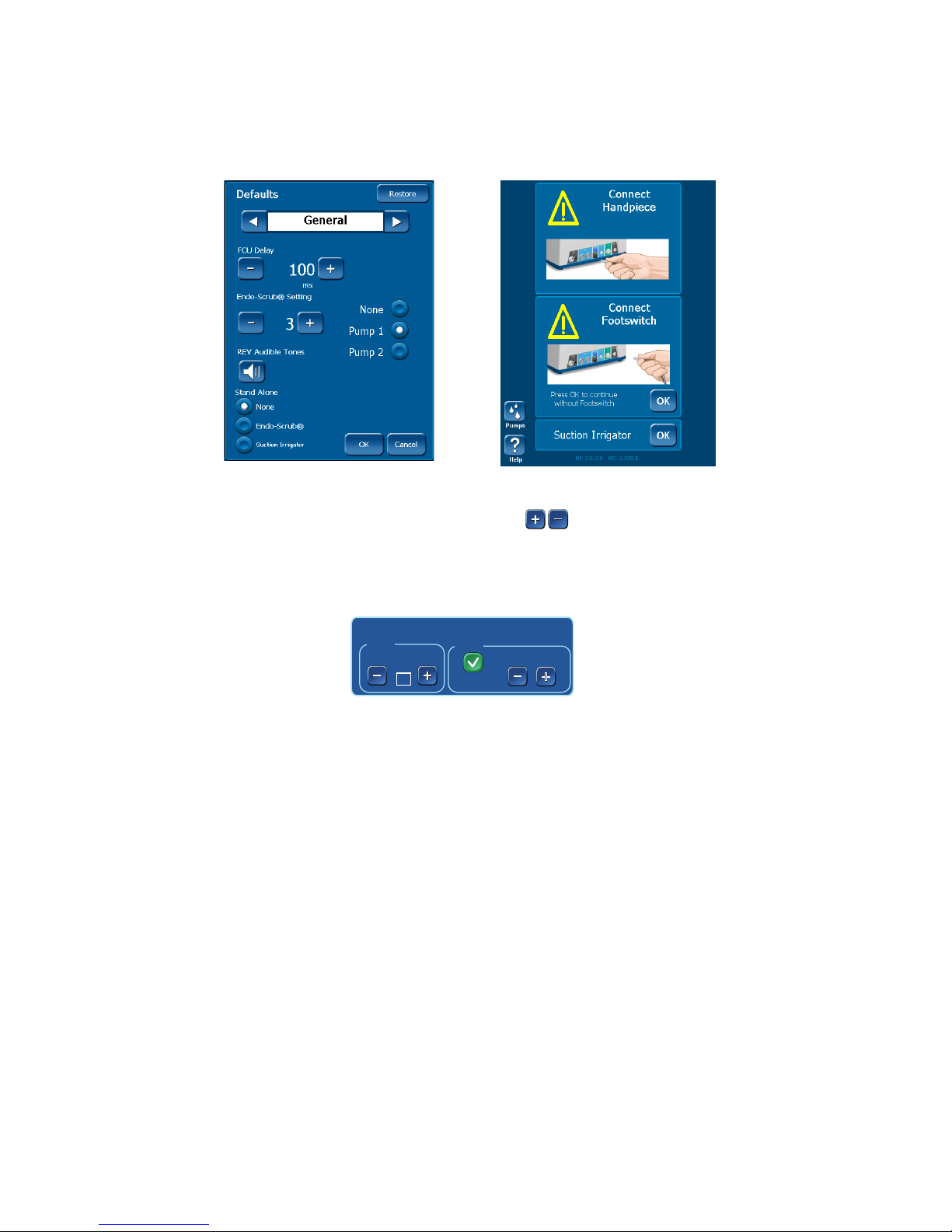
SUCTION IRRIGATOR IN STANDALONE MODE
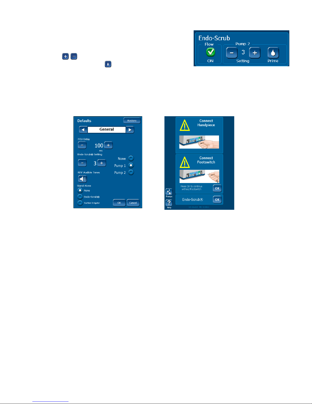
The Suction Irrigator tool can operate as a standalone device by changing the IPC system defaults.
1. On the Defaults menu (Figure 3-3), in the Stand Alone section, select Suction Irrigator and then press [OK].
2. On the Handpiece Connection screen (Figure 3-4), in the Suction Irrigator box, press [OK].
Figure 3-3. IPC General System Default Menu Figure 3-4.Handpiece Connection Screen
SUCTION IRRIGATOR TOUCHSCREEN CONTROLS
To set or adjust Suction Irrigator controls, on the IPC touchscreen, in the Suction Irrigator control box (Figure 3-5), do the following:
• To set the tubing size, in the Size control box, press the plus and minus buttons.
Note: The system defaults to size 8.
• To enable or disable the irrigation ow, in the Flow control box, select the On/O box.
• To adjust the ow rate, in the Flow control box, press the plus and minus buttons.
+
Figure 3-5. Suction Irrigator Touchscreen
Suction Irrigator
Size
8
Fr
Flow
IIIIIIIII
+
+
On
+
+
3-2
ENDO-SCRUB 2
(5)
ENDOSCRUB 2
The following instructions for the Endo-Scrub 2 are in addition to “Set up the IPC” general assembly instructions. Complete IPC setup, then continue
to the instructions below. Refer to the Endo-Scrub 2 System Instructions for Use, Endo-Scrub Sheaths Instructions for Use and Endo-Scrub 2 Finger
Switch Instructions for Use for additional information.
The IPC System incorporates Endo-Scrub 2 functionality by using irrigation pump number one (1) and controlling operation with the touch screen
and an external foot pedal or nger switch.
DO NOT use the Endo-Scrub 2 for infusion, for disinfection or sterilization of an endoscope, or for suction removal of blood and debris.
Use the Endo-Scrub 2 sheath only with an endoscope listed on the sheath product label, as malfunction or poor performance could result.
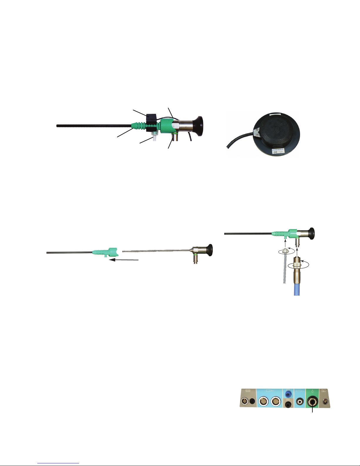
Figure 4-1. Endo-Scrub 2 Finger Switch Figure 4-2. Endo-Scrub 2 Foot Pedal
(1)
(2)
1 Finger switch 4 Light connection
2 Endo-Scrub 2 sheath 5 Finger Switch cable
3 Irrigation connection
(3)
(4)
ENDOSCRUB 2 ASSEMBLY
1. Wet the endoscope.
2. Slowly, slide the approved endoscope into the Endo-Scrub 2 sheath (Figure 4-3).
3. Connect the irrigation tubing and a light source (Figure 4-4).
Figure 4-3. Endo-Scrub 2 Assembly Figure 4-4. Endo-Scrub 2 Assembly
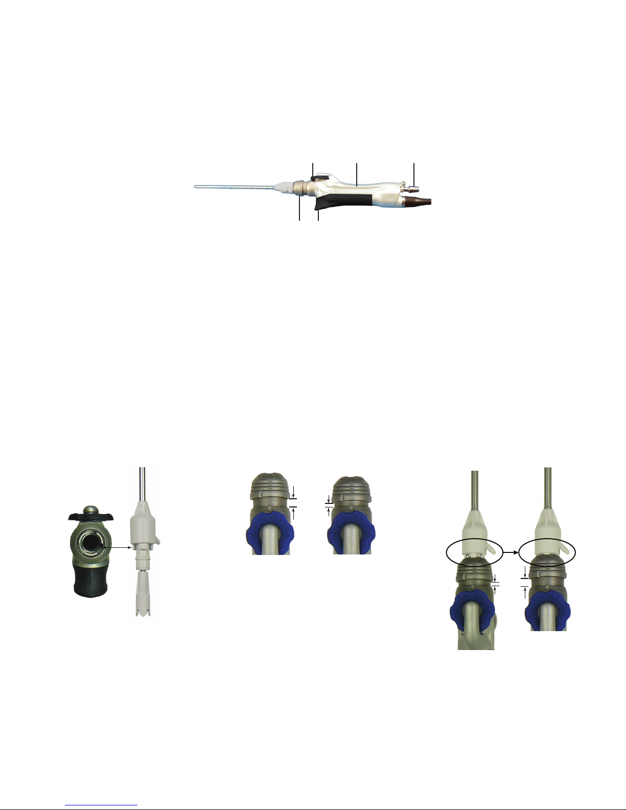
ENDOSCRUB 2 FINGER SWITCH ASSEMBLY
If using the Endo-Scrub 2 nger switch, complete the following:
1. Slide the nger switch onto the Endo-Scrub 2 sheath (Figure 4-1). Align the cutout section of the ring with the luer connector of the tubing
set. The nger switch is properly installed when the cutout section of the ring is rmly seated against the luer connector.
2. Activate the pump by pressing the actuator button located on the nger switch.
ENDOSCRUB 2 ACTIVATION
Note: The procedure below also applies if using the multifunction foot pedal.
1. To activate the Endo-Scrub wash cycle, press and release the nger switch.
2. To initiate a continuous ow of irrigant, press and hold the nger switch.
CONNECT ENDOSCRUB 2 TO IPC CONSOLE
1. Locate the Endo-Scrub 2 connector cover on the back of the IPC console (Figure 1-2).
2. Insert a small screwdriver in the notch on the cable connector cover and pull.
3. Connect the control switch cable to the cable connector.
4. Connect the Endo-Scrub 2 nger switch (Figure 4-1) or the foot pedal (Figure 4-2) to the
console (Figure 4-5).
Figure 4-5. IPC Endo-Scrub 2 Connection Port
(1)
1 Finger switch or foot pedal connection port
4-1
ENDO-SCRUB 2
+
+
ENDOSCRUB 2 TOUCHSCREEN CONTROLS
To set or adjust Endo-Scrub 2 controls, on the IPC touchscreen, in the Flow section of the
Endo-Scrub control box (Figure 4-6), do the following:
• To enable the Endo-Scrub 2 , press the On/O check-box.
• To adjust the ow rate, press the plus button to increase ow rate or the minus button
to decrease ow rate.
• To prime the pump, press the prime button.
ENDOSCRUB 2 IN STANDALONE MODE
The Endo-Scrub 2 can operate as a standalone device by changing the IPC system defaults.
1. On the Defaults menu (Figure 4-7), in the Stand Alone section, select Endo-Scrub and then press [OK].
2. On the Handpiece Connection screen (Figure 4-8), in the Endo-Scrub box, press [OK].
Figure 4-7. IPC General System Default Menu Figure 4-8.Handpiece Connection Screen
Figure 4-6. Endo-Scrub 2 Touchscreen
ENDOSCRUB 2 CLEANING AND STERILIZATION INSTRUCTIONS
Refer to document 68E4005 in the Cleaning and Sterilization section.
Endo-Scrub 2 Foot Pedal Cleaning
Important: If debris is found under the foot pedal boot, return for warranty service.
DO NOT immerse or sterilize the foot pedal unit.
DO NOT use alcohol, other solvents or abrasive cleaners.
1. Wipe down the Endo-Scrub 2 foot pedal with a cloth dampened with a neutral enzymatic detergent, pH 6.0-8.0 or phenol based
disinfectant.
2. Dry the unit with a clean, non-abrasive cloth.
4-2
SPINE SHAVER (SC1) HANDPIECE
12 3
45
SPINE SHAVER SC1 HANDPIECE
DEVICE DESCRIPTION
The following instructions for the Spine Shaver (SC1) Handpiece are in addition to “Set up the IPC” general assembly instructions. Complete IPC
setup, then continue to the instructions below. Refer to the Midas Rex User’s Guide for additional information.
The IPC incorporates the Midas Rex Spine Shaver (SC1) at pump 2. Control operation of the Midas Rex Spine Shaver (SC1) with the IPC touchscreen
and the multifunction foot pedal.
Figure 5-1. Spine Shaver (SC1) Handpiece
1 Finger wheel 4 Finger wheel lock
2 Irrigation tubing groove 5 Locking collar
3 Suction barb
SPINE SHAVER SC1 BLADE OR BUR ASSEMBLY
1. Insert the tool aligning the tabs with the notches (Figure 5-2). Orientate the irrigation barb to the left or right side.
Note: The StraightShot M4 uses a four-tab alignment system.
• For rotating straight blades, orient the irrigation barb at the 3 o’clock position for right-handed surgeons and 9 o’clock for left-handed
surgeons.
• For rotating curved blades, orient the irrigation barb at 3 o’clock.
2. Press the locking collar (Figure 5-3).
3. Release the locking collar.
Note: If collar does not return to full out position adjust the nger wheel with small back-and-forth motions until collar pops out.
4. Pull on the blade or bur to ensure engagement and visually check to make sure the distal tip of the inner blade is in contact with the distal
tip of the outer cannula (Figure 5-4).
Figure 5-2. Spine Shaver (SC1) Assembly Figure 5-3. Spine Shaver (SC1) Assembly Figure 5-4. Spine Shaver (SC1) Assembly
5-1

SPINE SHAVER (SC1) HANDPIECE
+
12
SPINE SHAVER SC1 SUCTION AND IRRIGATION TUBE ASSEMBLY
1. Attach a suction tube to the suction source (Figure 5-5) and an irrigation tube on the irrigation barb (Figure 5-5).
2. Secure suction and irrigation in the irrigation groove on the handpiece (Figure 5-6).
Figure 5-5. Spine Shaver (SC1) Suction Irrigation Assembly Figure 5-6. Spine Shaver (SC1) Suction Irrigation Assembly
CONNECT SPINE SHAVER SC1 TO IPC CONSOLE
Locate the Spine Shaver (SC1) connection port on the connector panel (Figure 5-7) and insert the connector.
Note: To insert multi-pin connectors (indicated by a silver or red mark on the connector), align the mark on the connector to the mark on the
console, then insert the connector.
Figure 5-7. Spine Shaver (SC1) IPC Connection Ports
1 Spine Shaver (SC1) handpiece connection port
2 Multifunction foot pedal connection port
SPINE SHAVER SC1 TOUCHSCREEN CONTROLS
To set or adjust Spine Shaver (SC1) controls, on the IPC touchscreen, in the control box (Figure 5-8), do the following:
• To change rotation mode, in the Mode control box select OSC (oscillating) or FWD (forward).
• To adjust speed, in the Speed control box, press the plus button to increase speed and the
minus button to decrease speed.
+
Forward Mode: Default, 12000 rpm; variable adjustment from 50 to 12000 rpm.
Oscillate Mode: Default, 3400 cpm; variable adjustment from 50 to 5000 rpm.
• To adjust the irrigation ow rate, in the Pump control box, press the plus button to increase
ow rate or the minus button to decrease ow rate. If intermittent ow is available, pressing
the plus or minus button progresses the system through intermittent and continuous ow. The
system displays Intermittent when in intermittent ow mode.
Forward Mode: Default, 30 cc per minute.
Oscillate Mode: Default, 60 cc per minute.
Note: To adjust ow rate, you can use the touchscreen or the IntelliFlow Irrigation remote
control.
• In oscillating mode only, you can use the Blade Position control box to do any of the
following:
To rotate the inner blade 180 press the delta button.
180º
To rotate the inner blade in small increments, press the clockwise or counter-clockwise buttons.
Note: The motion indicator indicates rotation direction of the blade.
Figure 5-8. Spine Shaver (SC1) Touchscreen
SC1 Handpiece
Speed
3400
Blade Position
Pump 2
60
cc/min
Mode
OSC
+
+
CPM
+
+
Prime
FWD
180°
• To rotate the outer blade, use the nger wheel (Figure 5-1).
5-2

SPINE SHAVER SC1 BLADE CONTROL
1
24
Note: Periodically submerse blade tip in sterile water, with suction on, to keep
blades clear during the procedure.
• To rotate the outer blade (Figure 5-9), use the nger wheel (Figure 5-1).
• To rotate the inner blade, use the Blade Position control box on the IPC
touchscreen.
SPINE SHAVER (SC1) HANDPIECE
Figure 5-9. Blade Dissection
3
1 Suction ow in through inner blade
Irrigation ow between inner and outer blades
2 Outer blade
3 Inner blade
4 Outer sleeve
SPINE SHAVER SC1 MULTIFUNCTION FOOT PEDAL
Figure 5-10. Multifunction Foot Pedal & Y-Splitter
CONTROLS
Important: By default, press each button on the foot pedal for at least 100 mS
for the selection to become active. Use the IPC touch screen Settings screen to
change the default value.
1
Use the multifunction foot pedal (Figure 5-10) to control the following:
• To select forward or oscillating mode, press the mode button.
• To start or adjust the speed of a handpiece in variable mode, press the foot
pedal.
• To rotate the inner blade (180) press the control button.
• To change the handpiece, press the handpiece button.
5
4
1 Mode button 5 Foot pedal
2 Handpiece button 6 Y-Splitter
3 Control button 7 Port 1
4 Slip-resistant food pad 8 Port 2
SPINE SHAVER SC1 CLEANING AND STERILIZATION INSTRUCTIONS
Refer to document 68E3282 in the Cleaning and Sterilization section.
SPINE SHAVER SC1 TECHNICAL SPECIFICATIONS
Spine Shaver (SC1) ED100
Size 14.3 cm Length x 1.8 cm Width (ED100)
Weight 228 g ED100
Speed 50-5000 rpm oscillate
50-12000 rpm forward
Duty Cycle for Applied Part Maximum on time = 60 seconds. Minimum o time = 30 seconds.
2
3
1
5
6
7
8
2
3
4
5-3

 Loading...