

Page 1

Heli-FX™ EndoAnchor™ Systems, comprising the Heli-FX Guides, Heli-FX Appliers, EndoAnchor implants, and EndoAnchor
Cassettes.
Instructions for Use
CAUTION: Federal (United States) law restricts this device to sale by or on the order of a physician.
Read all Instructions carefully. Failure to properly follow the instructions, contraindications, warnings, and precautions may
lead to serious surgical consequences or injury to the patient.
Page 2

© 2018 Medtronic. All rights reserved. Medtronic and Medtronic logo are trademarks of Medtronic. ™* Third party brands are
trademarks of their respective owners. All other brands are trademarks of a Medtronic company.
Page 3

Explanation of symbols that may appear on product labeling
Refer to the device labeling to see which symbols apply to this product.
Use-by date
Consult instructions for use at this website
Do not reuse
Catalog number
Lot number
Manufacturer
Do not use if package is damaged
Sterilized using ethylene oxide
Keep dry
Date of manufacture
MR Conditional
Quantity
Nonpyrogenic uid path
Nonpyrogenic uid path and implant
Nonpyrogenic implant
Debrillation-proof type CF applied part
IPX0 - no claim of protection from water ingress
Conformité Européenne (European Conformity). This symbol means that the device fully complies with applicable
European Union Acts.
Authorized Representative in the European Community
For US Audiences Only
Manufactured In
3
Page 4

Page 5

Table of Contents
1.0 Product description .................................................................................................................. 6
2.0 Indications for use ................................................................................................................... 9
3.0 Contraindications ..................................................................................................................... 9
4.0 Warnings and precautions ....................................................................................................... 9
5.0 Adverse events ...................................................................................................................... 10
6.0 How supplied ..........................................................................................................................11
7.0 Clinical data ............................................................................................................................11
8.0 Clinical use information ......................................................................................................... 12
9.0 Directions for use ................................................................................................................... 13
10.0 Imaging guidelines and postoperative follow-up ................................................................... 18
11.0 Definitions .............................................................................................................................. 18
12.0 Storage, transport, and disposal ........................................................................................... 18
13.0 EMC guidance and declaration ............................................................................................. 19
14.0 Disclaimer of warranty ........................................................................................................... 21
Instructions for Use
5
5
Page 6

1.0 Product description
Heli-FX™ Applier
The Heli-FX Applier is a sterile, single-patient use disposable device designed to implant one EndoAnchor implant at a time.
EndoAnchor implants are loaded into the Applier from the EndoAnchor Cassette by placing the distal end of the Applier into
an unused EndoAnchor port that each holds one EndoAnchor implant.
Caution: The EndoAnchor implant has a sharpened leading edge. Use caution when handling an Applier loaded with an
EndoAnchor implant.
The Heli-FX Applier can be reloaded and deployed multiple times for the same patient. The Applier is composed of a catheter
and a control handle. The control handle includes indicator lights, control buttons, and a 9-volt alkaline battery-powered
motor. The motor controls the EndoAnchor implant rotation. Figure 1 provides details on the indicator lights and control
buttons. The user passes the Applier catheter through the lumen of the Heli-FX Guide until the distal end of the Applier
contacts the endograft and vessel wall.
The Applier is available in 2 lengths: 86 cm and 114 cm.
Classifications
• Internally powered equipment
• Type CF (debrillation-proof) applied part
• Type IPX0 for water ingress
• The equipment is not suitable for use in the presence of a ammable anesthetic mixture with air or with oxygen or nitrous
oxide.
• Mode of operation: continuous operation
The EndoAnchor implant is implanted in a 2 stage process to allow the physician to retract the EndoAnchor implant and
reposition it prior to nal deployment. Audible tones and visible lights during operation indicate the position of the EndoAnchor
implant and the available direction of motion. Figure 1 details the components of the Heli-FX Applier.
1
2
3
4
5
6
7
Figure 1: Heli-FX Applier
1. Control handle
2. Catheter
3. Reverse control button
4. Forward control button
5. Green forward and reverse indicators
6. Error indicator
7. Flush port
Table 1 shows the Heli-FX Applier status and relevant lights, audible tones, and button denitions associated with each
status.
Table 1: Lights, audible tones, and buttons
Device Status Light Tone
Off Off None
Green Forward Arrow: Flashes
On/Self Check Sequence
Reverse Arrow: Flashes
Blue Indicator Light: Flashes
3 To nes
6
6
Instructions for Use
Page 7
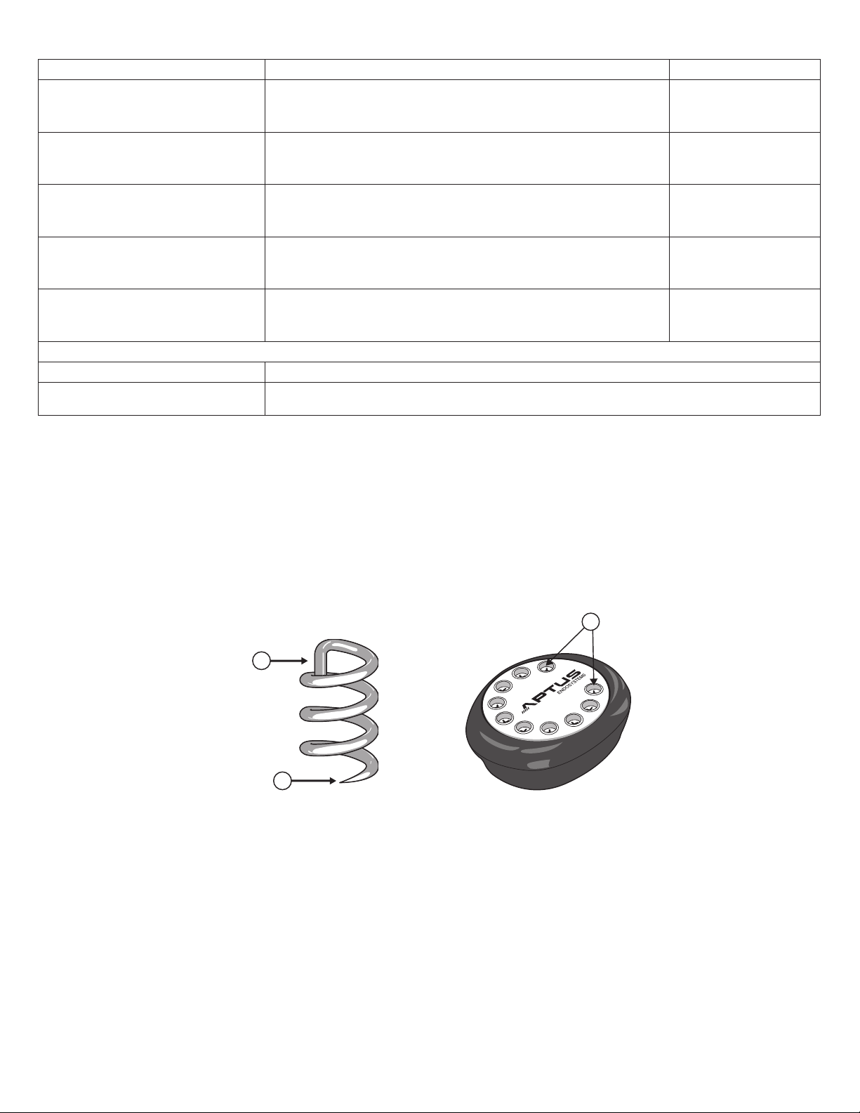
Table 1: Lights, audible tones, and buttons
2
1
Device Status Light Tone
Green Forward Arrow: Off
On/Ready
EndoAnchor Implant Loaded
Deployed to Pause State
Deployment Complete
Error
Button Actions
Forward Control Button Deploys an EndoAnchor Implant Forward
Reverse Control Button
Green Reverse Arrow: Flashes
Blue Indicator Light: Off
Green Forward Arrow: Flashes
Green Reverse Arrow: Off
Blue Indicator Light: Off
Green Forward Arrow: Flashes
Green Reverse Arrow: Flashes
Blue Indicator Light: Off
Green Forward Arrow: Off
Green Reverse Arrow: Flashes
Blue Indicator Light: Off
Green Forward Arrow: Off
Green Reverse Arrow: Flashes
Blue Indicator Light: Flashes
(a) Turns Heli-FX Applier On; (b) Loads an EndoAnchor implant; or (c) Withdraws
an EndoAnchor implant back in to the Applier from the Pause State
No Tones
2 To nes
4 To nes
3 To nes
4 To nes
EndoAnchor Implant and EndoAnchor Cassette
The EndoAnchor implant is designed to attach an endograft to the vessel wall. The EndoAnchor implant is manufactured from
0.5 mm diameter medical-grade wire. The EndoAnchor implant is approximately 4.5 mm in total length and approximately
3 mm in diameter. The sharp, leading end facilitates atraumatic deployment through the graft material and vessel wall. The
EndoAnchor implant also penetrates diffusely calcied tissue up to 2.0 mm thick. The cross-bar located at the proximal end
of the EndoAnchor implant prevents overpenetration of the implant. The body of the EndoAnchor implant has a helical shape,
allowing the EndoAnchor implant to engage tissue and attach the endograft to the vessel wall. Figure 2 is an illustration of the
EndoAnchor implant. 10 EndoAnchor implants are packaged in a sterile cassette allowing for easy and accurate loading into
the Heli-FX Applier. Figure 3 is an illustration of the EndoAnchor Cassette. Additional EndoAnchor implants are available in
an ancillary Cassette that contains 5 EndoAnchor implants.
1
Figure 2: EndoAnchor Implant
1. Crossbar
Figure 3: EndoAnchor Cassette
1. EndoAnchor ports
2. Leading end
Heli-FX Guide with Obturator
The Heli-FX Guide is a sterile, single patient use, disposable device that directs the Heli-FX Applier to the desired location for
implanting EndoAnchor implants. The Heli-FX Guide consists of a steerable guide catheter and control handle. The Obturator
(included with the Heli-FX Guide) has an atraumatic tip. The thoracic Obturator has a radiopaque marker within 2 mm of its
tip. The Obturator, which is compatible with a 0.89 mm (0.035 in) guidewire, allows the Guide to be advanced over the wire
within the patient's vasculature.
Rotating the deector knob on the control handle allows the distal tip of the Heli-FX Guide to be deected in a single direction
or straightened
A C-shaped radiopaque marker, located at the distal tip of the Heli-FX Guide, aids in orientation under uoroscopy. A straight
radiopaque marker, located at the outer curve of the deectable section of the Guide, indicates the direction of tip deection.
Figure 4 details the components of the Heli-FX Guide.
7
Instructions for Use
7
Page 8

3
7
6
4
Figure 4: Heli-FX Guide with Obturator
1. Control handle
2. Guide catheter
3. Radiopaque markers
4. Deector knob
5. Obturator
6. Hemostatic seal
7. Flush port
1
2
5
6
The Heli-FX Guide is available in 5 congurations of outer diameter, length, and deectable tip length (or "reach"). The
16 Fr outer diameter Guides have a working length of 62 cm and deectable tip lengths of 22 mm or 28 mm. The 18 Fr outer
diameter Guides have a working length of 90 cm and deectable tip lengths of 22 mm, 32 mm, or 42 mm.
Figure 5 demonstrates the reach provided by the different deected Guide congurations.
3
4
1
2
5
7
Figure 5: Heli-FX guides - available deectable tip lengths
1. 28 mm
2. 22 mm
3. 42 mm
4. 32 mm
5. 22 mm
6. 16 Fr OD
7. 18 Fr OD
8
8
Instructions for Use
Page 9

2.0 Indications for use
The Heli-FX EndoAnchor system is intended to provide xation and sealing between endovascular aortic grafts and the native
artery. The Heli-FX EndoAnchor system is indicated for use in patients whose endovascular grafts have exhibited migration
or endoleak, or are at risk of such complications, in whom augmented radial xation and/or sealing is required to regain or
maintain adequate aneurysm exclusion.
The EndoAnchor implant may be implanted at the time of the initial endograft placement, or during a secondary (i.e., repair)
procedure.
3.0 Contraindications
Treatment with the Heli-FX EndoAnchor system is contraindicated for use in the following circumstances:
• In patients with known allergies to the EndoAnchor implant material (MP35N-LT)
• In conjunction with the Endologix Powerlink™* endograft
4.0 Warnings and precautions
General
Read all instructions carefully. Failure to properly follow the instructions, contraindications, warnings, and precautions may
lead to serious surgical consequences or injury to the patient.
• Do not use if package is opened.
• The long-term performance of the EndoAnchor implant has not been established. All patients should be advised
that endovascular aneurysm treatment requires long-term, regular follow-up visits to assess the patient's health status and
endograft performance. The EndoAnchor implant does not reduce this requirement.
• The Heli-FX EndoAnchor system should only be used by physicians trained in vascular interventional techniques and
endovascular aneurysm repair. See Section 8.0 for physician training recommendations.
• The EndoAnchor implant and Heli-FX EndoAnchor system have been evaluated via in vitro testing and determined to be
compatible with the Cook Zenith™*, Cook Zenith TX2™*, Gore Excluder™*, Gore TAG™*, Medtronic AneuRx™, Medtronic
Endurant™, Medtronic Talent™ AAA, Medtronic Talent™ TAA, Medtronic Valiant Xcelerant™, Medtronic Valiant Captivia™,
and Medtronic Valiant Navion™ endografts.
• The endograft manufacturer's instructions for use provides recommendations regarding the aortic diameter ranges
appropriate for the endograft used. Because each endograft may be indicated for a unique range of aortic diameters, not
all models of the Heli-FX Guides apply to each endograft. Refer to Table 3 for Heli-FX Guide compatibility based on the
aortic diameter and location being treated. The appropriate model of Heli-FX Applier will be based on the Guide selected.
• Use with endografts other than those listed above has not been evaluated.
• Bench-top evaluations of the EndoAnchor implant with the Endologix Powerlink™* endograft demonstrated a propensity
for the Powerlink ePTFE graft material to tear upon loading of the EndoAnchor/endograft interface. The use of the
EndoAnchor implant with the Endologix Powerlink is contraindicated as a tear in the graft material could lead to endograft
migration or an endoleak channel at the site of the tear.
• In vitro accelerated durability testing of the EndoAnchor implant with the Medtronic Talent™ AAA endograft demonstrated
the potential for minor graft material hole elongation at the site of EndoAnchor implant penetration under severe axial
loading (see Section 7.0). Therefore, the EndoAnchor implant should be used with caution in conjunction with Medtronic
Talent™, Valiant Xcelerant™, and Valiant Captivia™ endografts, considering the benets of EndoAnchor implant use
versus the potential risks for the individual patient. Consider the use of additional EndoAnchor implants to further distribute
the axial load.
• The performance of the EndoAnchor implant has not been evaluated for securing multiple endograft components together.
Not securing EndoAnchor implants into aortic tissue could result in graft fabric damage, component separation, and
resultant Type III endoleaks.
• The performance of the EndoAnchor implant has not been evaluated for securing multiple anatomical structures together.
Such use could result in adverse patient consequences such as vascular perforation, bleeding, or embolic events.
• The performance of the EndoAnchor implant has not been evaluated in vessels other than the aorta. Use of the
EndoAnchor implant to secure endografts to other vessels may result in adverse patient consequences such as vascular
perforation, bleeding, or damage to adjacent structures.
Patient selection, treatment, and follow-up
• Access vessel diameter (measured inner wall to inner wall) and morphology (minimal tortuousity, occlusive disease, or
calcication) should be compatible with vascular access techniques and delivery systems with the prole of a 16 Fr or
18 Fr vascular introducer sheath. Vessels that are signicantly calcied, stenotic, tortuous, or thrombus-lined may preclude
placement of the Heli-FX EndoAnchor system.
• Key anatomic limitations in the intended aortic sealing zones that may prevent successful use of the Heli-FX system
include signicant thrombus, calcication, or plaque in the intended seal zone. Irregular or eccentric calcication, or
Instructions for Use
9
9
Page 10

plaque may compromise the xation of the EndoAnchor implant in the aortic tissue and inhibit proper xation and sealing
of the endograft. Patients exhibiting one or more of the features listed below were excluded from the reported clinical study
(see Section 7.0):
– Sealing zone thrombus, calcium, or plaque > 2 mm in thickness, or
– Sealing zone thrombus, calcium, or plaque covering > 50% (180°) of the vessel circumference
• The Heli-FX EndoAnchor system is not recommended in patients with known sensitivity or allergy to contrast agents that
are necessary for intraoperative and postoperative follow-up imaging, or whose renal function may be compromised by the
follow-up protocols required for the endovascular graft
• Do not use in patients with a known sensitivity or allergy to the EndoAnchor device materials (MP35N-LT, which is an alloy
of nickel, chromium, molybdenum, and cobalt)
Implant procedure
• Systemic anticoagulation should be used during the implantation procedure based on hospital and physician protocol. If
heparin is contraindicated, an alternative anticoagulant should be considered.
• Maintain guidewire position during insertion of the Heli-FX Guide with Obturator.
• Always use uoroscopy for guidance, delivery, and observation of any Heli-FX system components within the vasculature.
• Do not continue advancing any portion of the Heli-FX system if resistance is felt during advancement of the guidewire,
sheath, or catheter. Stop and assess the cause of resistance. Vessel, endograft, or catheter damage may occur.
• The use of the Heli-FX EndoAnchor system may require administration of intravascular contrast medium. Patients with
pre-existing renal insufciency may have an increased risk of renal failure postoperatively. Care should be taken to limit
the amount of contrast media used during the procedure.
• Care should be taken during manipulation of catheters, wires, and sheaths within an aneurysm and within a previously
placed endograft. Signicant disturbances may dislodge fragments of thrombus, which can cause distal embolization, or
cause displacement of the endograft, which can lead to endoleaks.
• Incorrect positioning of the Heli-FX Guide and Applier may lead to misdeployment of an EndoAnchor implant.
MRI safety and compatibility
• The EndoAnchor implants have been determined to be MR Conditional at 3T or less when the scanner is in Normal
Operating Mode with whole-body-averaged SAR of 2 W/kg, or in First Level Controlled Mode with a maximum wholebody-averaged SAR of 4 W/kg.
• Nonclinical testing using a Siemens 3T Trio whole body MR system with a body transmit/body receive coil and a spin echo
sequence (TR = 500 ms and TE = 35 ms) produced an image artifact extending less than 10 mm from the EndoAnchor
implants.
• The allowed values for the static magnetic eld, the spatial gradient, and the whole-body-averaged specic absorption rate
are given by the maximum allowed values for the endograft system with which the EndoAnchor implants are being used,
or by the EndoAnchor implants, whichever values are smaller.
• Because the EndoAnchor implants are small in dimension and have not shown signicant force, torque, and heating
effects, the values limiting the MRI exposure for a patient with a stent graft system including the EndoAnchor implants are
typically given by the endograft system.
• Please refer to documentation provided by the endograft system manufacturer for MR safety status of the endograft
system with which the EndoAnchor implants are being used.
5.0 Adverse events
Potential adverse events associated with use of the EndoAnchor implant
Potential adverse events that are associated with the Heli-FX EndoAnchor system, include, but are not limited to:
• Aneurysm rupture
• Death
• EndoAnchor implant embolization
• Endoleaks (Type III)
• Enteric stula
• Failure to correct/prevent Type I endoleak
• Failure to prevent endograft migration
• Infection
• Renal complications (renal artery occlusion/dissection or contrast-induced acute kidney injury)
• Stroke
• Surgical conversion to open repair
• Vascular access complications, including infection, pain, hematoma, pseudoaneurysm, arteriovenous stula
10
10
Instructions for Use
Page 11

• Vessel damage, including dissection, perforation, and spasm
Additional potential adverse events may be associated with endovascular aneurysm repair in general. Refer to the
Instructions for Use provided with the endograft for additional potential adverse events.
Adverse event reporting
Any complaints (including adverse events, unanticipated adverse device effects, and incidents) involving the Heli-FX
EndoAnchor system should be reported to Medtronic Vascular immediately.
6.0 How supplied
The Heli-FX EndoAnchor system components (Heli-FX Guide, Heli-FX Applier and Cassette with EndoAnchor implants) are
supplied sterile. The Heli-FX Applier package includes one EndoAnchor Cassette, containing 10 preloaded EndoAnchor
implants.
Do not use after the Use-by date printed on the label.
Table 2 details the available components of the Heli-FX EndoAnchor system.
Table 2: Heli-FX system components
System Component Model number
Heli-FX Applier with EndoAnchor Cassette (containing
Heli-FX system (16 Fr outer
diameter; 62 cm working length)
Heli-FX Applier with EndoAnchor Cassette (containing
Heli-FX Thoracic system (18 Fr
outer diameter; 90 cm working
length)
All Heli-FX Systems Ancillary EndoAnchor Cassette (containing 5 EndoAnchor implants) EC-05
10 EndoAnchor implants)
Heli-FX Guide (22 mm reach) SG-64
Heli-FX Guide (28 mm reach) HG-16-62-28
10 EndoAnchor implants)
Heli-FX Guide (22 mm reach) HG-18-90-22
Heli-FX Guide (32 mm reach) HG-18-90-32
Heli-FX Guide (42 mm reach) HG-18-90-42
SA-85
HA-18-114
The Heli-FX devices are intended for single use only. Do not reuse or resterilize the devices.
• Reprocessing or reuse of single-use devices may compromise the structural integrity of the device, essential material and
design characteristics, and lead to device failure.
• Reuse of single-use devices creates a potential risk of patient or user infections. Contamination of the device may lead to
injury, illness, or death of the patient.
• This product was tested for electrical safety for the intended single use only. Any reuse may pose the risk of electrical
shock, insufcient isolation, and temperatures elevated above the temperatures intended for the components.
7.0 Clinical data
Clinical study
The Heli-FX EndoAnchor system was evaluated in a prospective, single-arm, Investigational Device Exemption (IDE) trial
enrolling 155 subjects (145 male, average age 73 years) at 25 centers in the United States. The studied system uses an
identical EndoAnchor implant as the Heli-FX thoracic system. The EndoAnchor implant was evaluated in conjunction with an
investigational endograft in patients meeting standard elective infrarenal Endovascular aneurysm repair (EVAR) treatment
criteria, including the specic proximal neck characteristics as follows:
• Proximal neck length ≥ 12 mm
• Proximal neck diameters between 19 mm and 29 mm
• Proximal infrarenal neck angulation ≤ 60°, and
• Proximal neck thrombus, calcication and/or plaque ≤ 2 mm in thickness and ≤ 50% (180°) continuous coverage of the
vessel circumference in the sealing zone
The data presented below were generated in the aforementioned clinical trial. This study was not prospectively designed or
statistically powered to evaluate the safety and effectiveness of the EndoAnchor implant as a stand-alone device; however, it
contains important information related to the clinical use of the EndoAnchor implant. The investigational endograft studied in
conjunction with the EndoAnchor implant was designed specically for use with the EndoAnchor implant, and is composed
of a multilament woven polyester graft fabric with a nickel-titanium (Nitinol) sealing stent and unsupported main body
architecture. This endograft is not marketed and is not among the named devices listed in Section 4.0.
The study subjects were followed at 1, 6, and 12 months, and yearly thereafter per standard EVAR follow-up protocol. An
independent core lab was employed to evaluate imaging-related endpoints. The primary safety endpoint was freedom from
major adverse events (MAE) at 30 days. MAEs were dened as death, Myocardial Infarction, stroke, renal failure, respiratory
Instructions for Use
11
11
Page 12

failure, or paralysis. 4 MAEs occurred in 3 subjects (1.9%), compared to a reference rate of 11.1% for open surgical repair.
The primary effectiveness endpoint was successful aneurysm treatment at 1 year, dened as delivery success, absence
of Type I/III endoleaks, absence of migration ≥ 10 mm, and absence of aneurysm rupture or late conversion to open
repair. Effectiveness was measured at 97.4%, compared to a reference rate of 80%. 4 subjects (2.6%) did not meet the
primary effectiveness endpoint: 2 endograft component delivery failures at the index procedure, 1 intervention at 8 months
postimplant to address a Type I endoleak, and one Type III endoleak identied by the core lab at the 6-month follow-up
period.
Physicians implanted a total of 810 EndoAnchor implants (range 2-14, median 5 per patient) in 154 subjects. Implantation
of EndoAnchor implants took an average (SD) of 16.8 (11.8) minutes (range 2-125 minutes). There have been no reported
Unanticipated Adverse Device Effects (UADEs) associated with the EndoAnchor implant. Through 1-year follow-up, including
633 EndoAnchor implants in 119 subjects, the core lab did not observe any EndoAnchor implant fractures or any migrations
of EndoAnchor implants from their implanted positions. Through 1-year follow-up, no subjects had experienced proximal
endograft migration and one subject had a secondary intervention to address a Type I endoleak (1/119, 0.8%), which occurred
in the absence of endograft migration in a circumferentially incomplete aortic neck. A single Type III endoleak (1/119, 0.8%),
involving the separation of a proximal aortic cuff from the bifurcated endograft device, occurred in a subject whose bifurcated
device was not xed using EndoAnchor implants prior to cuff placement. After 1 year, a single subject was explanted in
response to caudal endograft migration despite EndoAnchor implant usage. At least 2 of the 4 EndoAnchor implants were
implanted in this subject into mural thrombus in the aortic neck and did not actually penetrate the aortic wall.
Caution: The EndoAnchor implant has undergone in vitro evaluations for compatibility and durability with the endograft
devices listed in Section 4.0. The transferability of these data to other endograft designs is not known and, therefore, use with
other endografts is not recommended.
Caution: The EndoAnchor implant has not undergone clinical evaluations in the thoracic or thoraco-abdominal (suprarenal)
aorta.
Preclinical data
Clinical data has been augmented with bench testing to evaluate the performance of the EndoAnchor implant with additional
Abdominal Aortic Aneurysm (AAA) and Thoracic Aortic Aneurysm (TAA) endografts, which have not undergone clinical
evaluation with the EndoAnchor implant. Bench testing included simulated procedural use and accelerated durability testing
(10-year equivalent). Durability testing was completed for the following AAA endografts: Cook Zenith™*, Gore Excluder™*,
and Medtronic AneuRx™, Endurant™, and Talent™. Bench evaluations demonstrated that the following TAA endografts use
the same graft material and construction as their AAA counterparts; thus durability testing was not repeated: Cook Zenith
TX2™*, Gore TAG™*, Medtronic Talent™ TAA, Medtronic Valiant Xcelerant™, Medtronic Valiant Captivia™, and Medtronic
Valiant Navion™.
All of the evaluated endografts (AAA and TAA) demonstrated compatibility with the anchoring procedure in an in vitrosimulated-use environment.
Note: The Medtronic Valiant Navion device was not evaluated in simulated use testing due to the similarity in device
construction and intended use conditions with the other endografts.
During accelerated durability testing, the Medtronic Talent™ AAA endograft demonstrated minor elongation of the
EndoAnchor implant penetration location in 3 of 8 (37.5%) of test samples. The maximum hole elongation seen was
1.3 mm, as compared to the EndoAnchor implant wire diameter of 0.5 mm. This situation occurred between 300 million and
400 million cycles (7.5-10 years equivalent). While this observation is believed to be due to the severe test conditions (worst-
case axial loading scenario and the lack of incorporation of the migration resistance provided by the Medtronic Talent™ AAA
endograft's longitudinal connecting bars), the EndoAnchor implant should be used with caution in Medtronic Talent™ AAA,
Valiant Xcelerant™, and Valiant Captivia™ endografts.
8.0 Clinical use information
Physician training
Always refer to the Instructions for Use supplied with the endograft system or the components with which the EndoAnchor
implants are being used to ensure proper knowledge of techniques regarding the endograft devices.
Caution: The Heli-FX EndoAnchor system should only be used by physicians trained in the use of the device and in vascular
interventional techniques, including endovascular aneurysm repair.
The recommended skill, knowledge, and resource requirements for physicians using the Heli-FX EndoAnchor system include:
• Knowledge of the complications associated with endovascular AAA and TAA repair
• A multidisciplinary team that has combined procedural experience with:
– Vascular access and related complications
– Nonselective and selective guidewire and catheter techniques
– Fluoroscopic and angiographic image interpretation
– Snare techniques
12
12
Instructions for Use
Page 13

– Appropriate use of radiographic contrast material
– Techniques to minimize radiation exposure
Inspection prior to use
Inspect the device and packaging to verify that no damage has occurred as a result of shipping. Do not use this device if
damage has occurred or if the sterile barrier has been damaged or broken. If damage has occurred, do not use the product.
Return to Medtronic Vascular, Inc. or your distributor.
Do not use beyond the Use-by date indicated on the packaging.
Prior to use, verify correct devices (appropriate Heli-FX Applier and Guide models for the anatomy being treated and
sufcient quantity of EndoAnchor implants) have been supplied for the patient by matching the device to the order prescribed
by the physician for that particular patient.
Recommended materials
• Heli-FX Guide with Obturator
• Heli-FX Applier with EndoAnchor Cassette
• 16 Fr or 18 Fr (or larger) introducer sheath, if desired
• 0.89 mm (0.035 in) guidewire, exchange length (260 cm or greater)
• Heparinized saline for catheter ush
• Alternative guidewires and other endovascular tools, per the physician's preference
9.0 Directions for use
Prior to use of the Heli-FX EndoAnchor system, review this Instructions for Use booklet. The following instructions embody
a basic guideline for EndoAnchor implant placement. Variations in the following procedures may be necessary. These
instructions are intended to help guide the physician and cannot substitute for the physician's judgment.
General use information
Standard techniques for placement of arterial access sheaths, guiding catheters, angiographic catheters, and guidewires
should be employed during use of the Heli-FX EndoAnchor system. The Heli-FX Guide with Obturator is compatible with
0.89 mm (0.035 in) diameter guidewires.
Preimplant planning
• Determine accurate anatomy and morphology of the intended aortic sealing zones for placement of the EndoAnchor
implants. Table 3 indicates the appropriate Heli-FX Guide based on the native aortic diameter being treated.
Table 3: Heli-FX Guide tip conguration and vessel diameter
Abdominal aortic sealing zone diameter 18 – 28 mm 28 – 32 mm
Heli-FX Guide tip length model number
Thoracic aortic sealing zone diameter 18 – 28 mm 28 – 38 mm 38 – 42 mm
Heli-FX Guide tip length model number
22 mm tip reach
SG-64
22 mm tip reach
HG-18-90-22
28 mm tip reach
HG-16-62-28
32 mm tip reach
HG-18-90-32
42 mm tip reach
HG-18-90-42
Caution: EndoAnchor implant locations should be based upon a detailed examination of the preoperative CT imaging in
cases involving irregular or eccentric plaque in the intended sealing zones. EndoAnchor implants should be implanted
only into areas of aortic tissue that is free of calcied plaque or thrombus, or where such pathology is diffuse and less than
2 mm in thickness. Attempting to place EndoAnchor implants into more severe plaque or thrombus may be associated with
implantation difculty and suboptimal endograft xation and/or sealing. Reference Section 4.0 and Section 7.0.
• If placing the EndoAnchor implants at the time of endovascular graft implantation, rst implant the endograft per the
manufacturer's instructions.
Heli-FX EndoAnchor system procedure preparation
1. Position patient on an imaging table, allowing uoroscopic visualization from the aortic arch to the femoral artery
bifurcations.
2. Secure access to a common femoral artery using standard technique with introducer sheath sizes appropriate for the
delivery systems being used. The 16 Fr outer diameter Heli-FX EndoAnchor systems are compatible with 16 Fr or larger
sheaths. The 18 Fr outer diameter Heli-FX EndoAnchor systems are compatible with 18 Fr or larger sheaths.
3. Using uoroscopic guidance, gain access to the patient's aorta with a 0.89 mm (0.035 in) guidewire through the femoral
access site.
4. Perform preimplant angiography to identify the location of the endograft and relevant vascular anatomy (such as great
vessels, visceral vessels).
Instructions for Use
13
13
Page 14

Heli-FX Guide insertion
1. Place an exchange length 0.89 mm (0.035 in) guidewire via the femoral access site into the desired region of the aorta.
The Heli-FX Guide may be placed via ipsilateral or contralateral approach.
2. EndoAnchor implant may be implanted at any time during endograft implantation; however, Medtronic Vascular
recommends completing endograft implantation before placing the EndoAnchor implants. If the physician chooses
to implant an EndoAnchor implant with a bifurcated AAA endograft before placing an iliac extension, the endograft's
contralateral gate may be cannulated by standard technique. Conrm proper endograft position before implanting an
EndoAnchor implant.
3. Select the appropriate Heli-FX Guide based on the diameter of the aorta being treated and the region in which the
endograft is being anchored. See Table 3.
4. Using heparinized saline, ush the Heli-FX Guide via the ush port and ush the Obturator via the proximal luer.
5. Insert the Obturator into the Guide.
6. Using uoroscopic guidance, advance the Heli-FX Guide and Obturator over the 0.89 mm (0.035 in) guidewire and
position it within the desired aortic sealing zone. Use C-shaped radiopaque marker on the distal tip of the Heli-FX Guide to
aid in uoroscopic visualization. To further aid in visualization, use the linear marker that is located along the length of the
deectable tip, on the wall opposite the direction of deection.
Note: Any release control mechanism of the endograft's proximal or distal stent must be released prior to the Heli-FX
Guide placement to ensure proper apposition of the endograft to the aortic neck sealing zone and to avoid interference
between the Heli-FX system and endograft delivery system.
7. Remove the guidewire and then the Obturator to minimize blood loss through the hemostatic seal of the Heli-FX Guide.
Caution: After the Obturator is withdrawn, the Heli-FX Guide can be used to manually inject contrast medium to conrm
proper endograft position before implanting an EndoAnchor implant. Before any manual injection, aspirate the Guide using
a syringe attached to the one-way valve on the back of the Guide control handle to prevent potential air ingress into the
patient's vasculature. Do not use a power injector to perform angiography through the Heli-FX Guide.
8. Under uoroscopic guidance, rotate the deector knob on the control handle clockwise to move the distal tip of the Heli-FX
Guide toward the rst implant location.
Note: The “C” marker at the distal end of the Guide is formed by a radiopaque material that only extends around a portion
of the circumference of the lumen. This marker appears as a “C” when directed toward the image intensier, as a solid
line when directed laterally relative to the image intensier, and as a “Ɔ” when directed away from the image intensier.
The “C” marker provides assistance with properly orienting the Guide relative to the graft and aorta at the appropriate
EndoAnchor implant location. A straight radiopaque marker on the distal end of the Heli-FX Guide is located on the side
opposite the direction of deection. This straight marker provides an indication of the proper rotational orientation of the
Guide prior to deection. In the lateral view, position the straight radiopaque marker on the opposite side of the intended
deployment surface. When the deector knob is rotated, the Guide tip will deect in the opposite direction relative to the
straight marker. It is recommended to implant the EndoAnchor implant while viewing the Guide laterally to the image
intensier (the “C” marker should appear as a solid line parallel to the graft and aortic wall as shown in Figure 6).
14
14
Instructions for Use
Page 15

1
2
3
4
Figure 6: Direction of Guide deection relative to straight marker
1. Straight marker
2. Direction of Guide deection
3. Straight marker
4. EndoAnchor implant deployment location
Heli-FX Applier preparation
1. Select the appropriate length of Heli-FX Applier based on the Guide being used and the anatomical location being treated.
2. To turn on the Heli-FX Applier, rmly press and hold the middle of the Reverse Control button for at least 5 seconds, or
until the motor starts. This will initiate a self-check sequence with audible tones and visible green lights. At the end of
this sequence, the reverse green arrow will be ashing, indicating that the Applier is ready to load the rst EndoAnchor
implant. Figure 1 provides an illustration of the Heli-FX Applier control handle.
Caution: If at the end of the self-check sequence the blue indicator light is illuminated, the Heli-FX Applier has
encountered an error and should not be used. The blue light indicates an internal problem and that the device is
nonfunctional. If the blue indicator light illuminates, replace the Applier with a new one and repeat the sequence for turning
it on.
3. Flush the inner lumen of the Heli-FX Applier with heparinized saline via the ush port.
4. Load the Applier by rmly pressing the middle of the Reverse Control button. While the motor is running, insert the distal
end of the Applier catheter into an unused EndoAnchor port on the EndoAnchor Cassette. Figure 7 shows examples of
used and unused EndoAnchor ports. The reverse green arrow will ash and the EndoAnchor implant will be loaded from
the cassette into the distal end of the Heli-FX Applier. When the EndoAnchor implant is loaded, 2 audible tones can be
heard, and the forward green arrow will ash, indicating that the rst stage of EndoAnchor implant deployment is ready.
The EndoAnchor implant is now loaded into the Applier, and the Applier can be removed from the cassette.
1
2
Figure 7: EndoAnchor Cassette
1. Unused EndoAnchor port
2. Used EndoAnchor port
Instructions for Use
15
15
Page 16

Note: Verication of the loaded EndoAnchor implant may be done by visually inspecting the distal tip of the Heli-FX Applier.
Implant the EndoAnchor implant
1. Ensure that the Guide control handle is stabilized and insert the tip of the loaded Applier through the hemostatic seal of
the control handle.
2. Position the Guide at the desired location for EndoAnchor implant placement (See Figure 6).
– Place the EndoAnchor implants within the desired sealing zone, typically within the most proximal or most distal
endograft stent
– Distribute the EndoAnchor implants as evenly as possible around the circumference of the sealing stent
– The recommended minimum number of EndoAnchor implants is based on endograft type (bifurcated or tube), vessel
angulation, and native vessel diameter, and is independent of the extent of endograft oversizing. Recommended
minimums are conservative, based on theoretical worst-case modeling, and incorporate the results of accelerated
durability testing to demonstrate the ability of the interface between the EndoAnchor implant and endograft to withstand
the calculated cyclic loading. See Table 4 and Table 5. Additional or fewer EndoAnchor implants may be placed at the
physician's discretion. An ancillary EndoAnchor Cassette is available when up to 5 additional EndoAnchor implants
are desired beyond the EndoAnchor implants supplied with each Heli-FX Applier (for a total of up to 15 EndoAnchor
implants). For procedures requiring more than 15 EndoAnchor implants, use multiple Appliers.
Table 4: Recommended minimum numbers of EndoAnchor implants – bifurcated endografts
Aortic neck diameter (Proximal)
≤ 29 mm 4
30-32 mm 6
Graft angulation
≤ 60°
Table 5: Recommended minimum numbers of EndoAnchor implants – tube endografts
Aortic neck diameter (Proximal or Distal)
≤ 29 mm 4 4 4
30-32 mm 4 4 5
33-36 mm 4 5 7
37-40 mm 5 6 8
> 40 mm 5 7 9
≤ 60° > 60°-75° > 75°-90°
Graft angulation
Caution: EndoAnchor implants should not be placed in unsupported endograft sections or sections of grafts where the
stents are not fully attached to the graft fabric.
3. Under uoroscopic guidance, advance the Applier through the Guide until the Applier emerges from the distal end of the
Guide and makes contact with the endograft. Slowly, continue to advance the Applier until resistance is felt, indicating the
Applier is rmly pushing the endograft against the vessel wall. Deection of the Guide away from the endograft should be
visualized under uoroscopy.
Note: It is recommended to implant EndoAnchor implants in a lateral view as shown in Figure 8. In this orientation
the Heli-FX Guide's distal C-marker appears as a solid straight line. If, upon advancement of the Applier, the distal
C-marker of the Guide changes from a straight line to resemble a "C" shape, this indicates that the Applier is no longer
perpendicular to the endograft (see Figure 9). If this occurs, the apposition force should be reduced by slightly retracting
the Applier, and the Guide repositioned as necessary. See Figure 8 for proper implant orientation. Attempting to implant
EndoAnchor implants in a tangential orientation may result in implant difculty and suboptimal endograft xation or
sealing.
4. Using the control handle of the Heli-FX Applier, rmly press the middle of the Forward control button for the rst stage
of EndoAnchor implant deployment. The EndoAnchor implant will partially deploy and pause. Four audible tones should
be heard and the forward and reverse arrow lights will alternate, indicating that the operator may continue deployment or
withdraw the EndoAnchor implant back into the Applier.
Note: If the EndoAnchor implant is not in the desired location, rmly press the middle of the reverse control button to
rehouse the EndoAnchor implant inside the Applier and reposition the Applier.
16
16
Instructions for Use
Page 17

Figure 8: Proper EndoAnchor implant placement Figure 9: Improper EndoAnchor implant placement.
Note: Assess successful EndoAnchor implant penetration by verifying that the tip of the EndoAnchor implant can be seen
outside of the stent structure during the pause state.
5. If the EndoAnchor implant is in the desired location, complete the nal stage of EndoAnchor implant deployment by rmly
pressing the middle of the Forward control button. When this stage is complete, 3 audible tones are heard and the reverse
green arrow ashes.
Warning: Do not attempt to deploy an EndoAnchor implant without rst conrming that the position of the Heli-FX Applier
is rmly against the endograft and aortic wall. Deployment of an EndoAnchor implant without proper apposition may result
in poor endograft xation or a dislodged EndoAnchor implant, which may require endovascular or surgical intervention to
retrieve.
Caution: Under uoroscopy, carefully and slowly retract the Heli-FX Applier away from the endograft wall to ensure that it
is released from the deployed EndoAnchor implant.
6. Remove the Applier leaving the Guide in place. Under uoroscopy, visually conrm the placement of the EndoAnchor
implant.
Caution: Withdraw the Applier slowly from the Guide in order to prevent potential air ingress.
Warning: In the event of power loss to the Heli-FX Applier when an EndoAnchor implant is partially deployed in a patient,
the EndoAnchor implant may be removed by manually rotating the handle and catheter in a counter-clockwise direction
until the EndoAnchor implant disengages from the endograft and tissue. The Applier can then be removed from the Guide.
7. Flush the Heli-FX Guide and Applier with heparinized saline to prevent clotting in the lumen, as needed.
8. Load the next EndoAnchor implant by repeating the steps as described previously.
9. Prior to repositioning the Heli-FX Guide for deployment of additional anchors, straighten the tip of the Guide by turning the
deector knob counterclockwise. To reposition the Guide, rotate the control handle to move the Guide to the next location
for EndoAnchor implant deployment and deect the Guide tip by turning the deector knob clockwise. The linear marker
on the outer curve of the deectable tip can be used as an aid in rotating the Guide with the tip straightened. Repeat the
deployment of EndoAnchor implants as desired. Reference the recommended minimum numbers of anchors provided in
Table 4 and Table 5.
Caution: To prevent accidental dislodgement or movement of the endograft, always straighten the deectable tip of the
Heli-FX Guide before rotating it within the endograft.
10. After deployment of the last EndoAnchor implant, remove the Heli-FX Applier. Straighten the Guide by turning the
Deector Knob counterclockwise. Readvance the Obturator through the hemostatic seal of the control handle on the Heli-
FX Guide. Then advance a 0.89 mm (0.035 in) guidewire through the Obturator.
11. Remove only the Heli-FX Guide and Obturator, leaving the 0.89 mm (0.035 in) guidewire in position.
End of procedure
1. Perform postimplant aortic angiography to evaluate implantation of EndoAnchor implants.
2. Check for endoleaks. If an endoleak is observed, use standard endovascular techniques to resolve. Additional
EndoAnchor implants may be placed as described previously, if necessary.
3. Check for proper location, blood ow, and patency of endograft.
4. Remove the 0.89 mm (0.035 in) guidewires and femoral access sheath (if used) and close the femoral arteriotomy
according to standard practice.
17
Instructions for Use
17
Page 18

10.0 Imaging guidelines and postoperative follow-up
General
The long-term safety and effectiveness of the EndoAnchor implant has not been established; thus Medtronic does not
recommend altering the endograft manufacturer's follow-up schedule solely due to EndoAnchor implant use during the initial
implant.
The long-term effectiveness of secondary endovascular interventions to address failures of previously placed aortic
endografts also has not been established. Therefore, Medtronic recommends consideration of an enhanced follow-up
schedule in patients who have exhibited migration or Type I endoleak, and who have been treated with the EndoAnchor
implant as part of a secondary intervention. Typically, enhanced follow-up includes reverting to the follow-up schedule that
was recommended after initial endograft implantation. Consult the endograft manufacturer's Instructions for Use.
Abdominal radiographs
The integrity of EndoAnchor implants placed in conjunction with AAA endografts is best assessed via abdominal radiograph.
The following abdominal x-ray views are recommended for optimal visualization of the EndoAnchor implants and for
assessing the position of the EndoAnchor implants relative to the endograft.
• Supine-frontal anteroposterior (AP)
• Lateral
• 30° Left Posterior Oblique (LPO)
• 30° Right Posterior Oblique (RPO)
Thoracic radiographs
The integrity of EndoAnchor implants placed in conjunction with TAA endografts is best assessed via chest x-ray. The
following thoracic x-ray views are recommended for optimal visualization of the EndoAnchor implants and for assessing the
position of the EndoAnchor implants relative to the endograft.
• Supine-frontal (AP)
• Lateral
Ensure the entire area of interest is captured on each single image. For the EndoAnchor implant, this includes the aortic neck
region of the endograft. Other areas may be of interest to examine for overall endograft performance. Refer to the endograft
manufacturer's guidelines for endograft imaging. Medtronic recommends imaging via abdominal or thoracic radiographs as
appropriate at each normally scheduled imaging follow-up interval.
MRI safety and compatibility
The EndoAnchor implant has been determined to be MR Conditional. Refer to Section 4.0.
Additional surveillance and treatment
Additional surveillance and possible treatment is recommended for patients whose follow-up imaging indicates EndoAnchor
implant movement or loss of integrity. Patients exhibiting Type I endoleak and endograft migration should be considered for
urgent treatment.
11.0 Denitions
Caution: A Caution indicates that particular service procedures or precautions must be followed to
avoid possible damage to the product.
Contraindication: A Contraindication identies a condition under which the device should not be used
because the risk of use outweighs any possible benet.
Note: A Note indicates special information to facilitate use of the product or to clarify important
information.
Warning: A Warning indicates that the personal safety of the patient or physician may be involved.
Disregarding a warning could result in injury to the patient or physician.
12.0 Storage, transport, and disposal
Follow local governing ordinances and recycling plans regarding disposal or recycling of the device components. Do not
incinerate the Heli-FX Applier unit, as the enclosed batteries may explode at excessive temperatures.
Environmental conditions:
• Storage conditions: Keep dry
• Operating conditions: (10 to 40°C) (30-75% RH) (700-1060 hPa)
• Transportation conditions: (-18° to +60°C) (15-90% RH)
18
18
Instructions for Use
Page 19

13.0 EMC guidance and declaration
This equipment has been tested and found to comply with the EMC limits for the Medical Device Directive 93/42/EEC (EN
55011 Class B and EN 60601-1-2). These limits are designed to provide reasonable protection against harmful interference
in a typical medical installation. The equipment generates, uses, and can radiate radio frequency energy and, if not used
in accordance with the instructions, may cause harmful interference to other devices in the vicinity. However, there is no
guarantee that interference will not occur in a particular setting.
Table 6: Guidance and manufacturer's declaration – electromagnetic emissions
The Heli-FX Applier is intended for use in the electromagnetic environment specied below. The customer or the user of the Heli-FX
Applier should assure that it is used in such an environment.
Emissions test Compliance Electromagnetic environment-guidance
RF emissions CISPR 11 Group 1 The Heli-FX Applier uses RF energy only for its internal function.
RF emissions CISPR 11 Class B The Heli-FX Applier is suitable for use in all establishments, including
Harmonic emissions IEC 61000 -
Not applicable
3-2
Voltage uctuations/ Flicker
Not applicable
emissions IEC 61000-3-3
Table 7: Guidance and manufacturer's declaration – electromagnetic immunity
The Heli-FX Applier is intended for use in the electromagnetic environment specied below. The customer or the user of the Heli-FX
Applier should assure that it is used in such an environment.
Immunity test IEC 60601 test level Compliance level Electromagnetic environment-guidance
Electrostatic discharge (ESD)
IEC 61000-4-2
Electrical fast Transient/burst
IEC 61000-4-4
Surge IEC 61000-4-5 ± 1 kV lines to lines
Voltage dips, short interruptions,
and voltage variations on power
supply input lines IEC 61000-4-11
Power frequency (50/60 Hz)
magnetic eld IEC 61000-4-8
± 6 kV contact
± 8 kV air
± 2 kV for power supply
lines
± 1 kV for input/output lines
± 2 kV lines to earth
< 5% U
for 0.5 cycle
(> 95% dip in UT)
T
40% UT (60% dip in UT) for
5 cycles
70% (30% dip in UT) for
25 cycles
< 5% (> 95% dip in UT) for
5 sec
Note: - U
application of the test level.
is the a.c. mains voltage prior to
T
3 A/m 3 A /m Power frequency magnetic elds should be at
Therefore, its RF emissions are very low and are not likely to cause
any interference in nearby electronic equipment.
domestic establishments.
± 6 kV contact
± 8 kV air
Floors should be wood, concrete, or ceramic
tile. If oors are covered with synthetic material,
the relative humidity should be at least 30%.
Not applicable
Not applicable
Not applicable
levels characteristic of a typical location in a
typical commercial or hospital environment.
Conducted RF 3 Vrms 3 Vrms Portable and mobile RF communications
IEC 61000-4-6 150 kHz to 80 MHz
equipment should be used no closer to any
part of the Heli-FX Applier, including cables,
than the recommended separation distance
calculated from the equation applicable to the
frequency of the transmitter.
Recommended separation distance
Radiated RF 3 V/m
d= 1.2
Instructions for Use
√P
19
19
Page 20

Table 7: Guidance and manufacturer's declaration – electromagnetic immunity
The Heli-FX Applier is intended for use in the electromagnetic environment specied below. The customer or the user of the Heli-FX
Applier should assure that it is used in such an environment.
Immunity test IEC 60601 test level Compliance level Electromagnetic environment-guidance
IEC 61000-4-3 80 MHz to 2.5 GHz 3 V/m
d= 1.2
d= 2.3
√P
√P
where P is the maximum output power rating
of the transmitter in watts (W) according to
the transmitter manufacturer and d is the
recommended separation distance in meters
(m).
Field strength from xed RF transmitters, as
determined by an electromagnetic site survey
should be less than the compliance level in
each frequency rangeb.
Interference may occur in the vicinity of
equipment marked with the following symbol:
Note 1 – At 80 MHz and 800 MHz, the higher frequency range applies.
Note 2 – These guidelines may not apply in all situations. Electromagnetic propagation is affected by absorption and reection from
structures, objects, and people.
a
Field strengths from xed transmitters, such as base stations for radio (cellular/cordless) and land mobile radios, amateur radio, AM and
FM radio broadcast, and TV broadcast cannot be predicted with theoretical accuracy. To assess the electromagnetic environment due
to xed RF transmitters, an electromagnetic site survey should be considered. If the measured eld strength in the location in which the
Heli-FX Applier is used exceeds the applicable RF compliance level above, the Heli-FX Applier should be observed to verify normal
operation. If abnormal performance is observed, additional measures may be necessary, such as reorienting or relocating the Heli-FX
Applier.
b
Over the frequency range 150 kHz to 80 MHz, eld strengths should be less than 3 V/m.
80 MHz to
800 MHz
800 MHz to
2.5 GHz
a
,
20
20
Instructions for Use
Page 21

Table 8: Recommended separation distances between portable and mobile RF communications equipment and the Heli-
FX Applier
The Heli-FX Applier is intended for use in an electromagnetic environment in which radiated RF disturbances are controlled. The
customer or the user of the Heli-FX Applier can help prevent electromagnetic interference by maintaining a minimum distance between
portable and mobile RF communications equipment (transmitters) and the Heli-FX Applier as recommended below, according to the
maximum output power of the communications equipment.
Rated maximum output power of
transmitter
W
0.01 0.12 0.12 0.23
0.1 0.38 0.38 0.73
1 1.2 1.2 2.3
10 3.8 3.8 7.3
100 12 12 23
For transmitters rated at a maximum output power not listed above, the recommended separation distance (d) in meters (m) can
be estimated using the equation applicable to the frequency of the transmitter, where P is the maximum output power rating of the
transmitter in watts (W) according to the transmitter manufacturer.
Note 1 – At 80 MHz and 800 MHz, the separation distance for the higher frequency range applies.
Note 2 – These guidelines may not apply in all situations. Electromagnetic propagation is affected by absorption and reection from
structures, objects, and people.
150 kHz to 80 MHz
d= 1.2
Separation distance according to frequency of transmitter
meters (m)
80 MHz to 800 MHz
√P
d= 1.2
√P
800 MHz to 2.5 GHz
√P
d= 2.3
NOTE: If electromagnetic interference is suspected, reorient the equipment with respect to the source of radiated
interference. If interference continues, contact Medtronic for further guidance.
14.0 Disclaimer of warranty
ALTHOUGH THE HELI-FX ENDOANCHOR SYSTEM, HEREAFTER REFERRED TO AS THE 'PRODUCT', HAS BEEN
MANUFACTURED UNDER CAREFULLY CONTROLLED CONDITIONS, MEDTRONIC, INC., MEDTRONIC VASCULAR,
INC., AND THEIR RESPECTIVE AFFILIATES, (COLLECTIVELY “MEDTRONIC”) HAVE NO CONTROL OVER THE
CONDITIONS UNDER WHICH THIS PRODUCT IS USED. THE WARNINGS CONTAINED IN THE PRODUCT LABELING
PROVIDE MORE DETAILED INFORMATION AND ARE CONSIDERED AN INTEGRAL PART OF THIS DISCLAIMER OF
WARRANTY. MEDTRONIC, THEREFORE, DISCLAIMS ALL WARRANTIES, BOTH EXPRESSED AND IMPLIED, WITH
RESPECT TO THE PRODUCT, INCLUDING, BUT NOT LIMITED TO, ANY IMPLIED WARRANTY OF MERCHANTABILITY
OR FITNESS FOR A PARTICULAR PURPOSE. MEDTRONIC SHALL NOT BE LIABLE TO ANY PERSON OR ENTITY FOR
ANY MEDICAL EXPENSES OR ANY DIRECT, INCIDENTAL, OR CONSEQUENTIAL DAMAGES CAUSED BY ANY USE,
DEFECT, FAILURE, OR MALFUNCTION OF THE PRODUCT, WHETHER A CLAIM FOR SUCH DAMAGES IS BASED
UPON WARRANTY, CONTRACT, TORT, OR OTHERWISE. NO PERSON HAS ANY AUTHORITY TO BIND MEDTRONIC
TO ANY REPRESENTATION OR WARRANTY WITH RESPECT TO THE PRODUCT.
The exclusions and limitations set out above are not intended to, and should not be construed so as to, contravene mandatory
provisions of applicable law. If any part or term of this Disclaimer of Warranty is held to be illegal, unenforceable, or in conict
with applicable law by a court of competent jurisdiction, the validity of the remaining portions of this Disclaimer of Warranty
shall not be affected, and all rights and obligations shall be construed and enforced as if this Disclaimer of Warranty did not
contain the particular part or term held to be invalid.
Instructions for Use
21
21
Page 22

Medtronic, Inc.
710 Medtronic Parkway
Minneapolis, MN 55432 USA
www.medtronic.com
Tel. (763) 514-4000
*M967542A001*
© 2018 Medtronic
M967542A001 Rev. 1B
 Loading...