

Medtronic E1DR06 Reference Guide

ENPULSE
E1DR00/20 Series
E2VDD00 Series
E2SR00 Series
™
Pacemaker Reference Guide
Caution: Federal law (USA) restricts this device to sale by or on
the order of a physician or properly licensed practitioner.


EnPulse Pacemaker Reference Guide
A guide to the EnPulse
pacemakers:
E1DR00 Series
E1DR20 Series
E2VDD00 Series
E2SR00 Series
Refer to the EnPulse Pacemaker
Programming Guide for information on
software and programming.

The following are trademarks of Medtronic:
Capture Management, Checklist, EnPulse, Fast Path, Implant Detection, Key Parameter History, Marker
Channel, Medtronic, Medtronic Carelink, Rate Profile Optimization, Remote Assistant, Auto-PVARP,
Quick Look II, Search AV+, Sensing Assurance, Observations, Sinus Preference, and Vision.

How to use this guide
Information is contained in two guides
Product information about EnPulse pacemakers and the associated
software for the 9790/C series programmer and the 2090 programmer is
presented in two separate guides.
This guide, the Pacemaker Reference Guide (PRG), provides detailed
information on EnPulse pacemakers.
The Pacemaker Programming Guide (PPG) accompanies the
programmer software for the EnPulse pacemakers and contains
instructions on how to use the programmers with these pacemakers.
About the Pacemaker Reference Guide
This guide describes in detail, how the pacemaker operates and specifies
the capabilities of each model.
■
Describes the pacing modes, rate response options, special therapy
features, telemetry types, and data collection options. In some cases,
guidelines are given on how to configure the pacemaker operation.
■
Contains troubleshooting information for electrical and hemodynamic
problems.
■
Specifies parameter and data collection capabilities, longevity
projections, and mechanical and electrical specifications.
■
Provides general warnings and cautions, potential interference
sources, and general indications for pacing.
■
Contains a glossary of terms.
How to use this guide
EnPulse Pacemaker Reference Guide iii

How to use this guide
About the Pacemaker Programming Guide
This guide presents the following information to use the
9790/C programmer and 2090 programmer.
■
How to set up and configure the programmer and access online help.
■
How to start a patient session, use the various follow-up features
during the session, and properly end the session.
■
How to use checklist to streamline a follow-up session.
■
How to view and print the patient’s ECG and EGM waveform traces.
■
How to configure the pacemaker to collect diagnostic data and how
to retrieve and view this information.
■
How to measure stimulation thresholds and sensing levels.
■
How to program parameter values and verify rate response
parameters settings.
■
How to run EP Studies.
iv EnPulse Pacemaker Reference Guide

Table of contents
Table of contents
How to use this guide iii
Information is contained in two guides iii
About the Pacemaker Reference Guide iii
About the Pacemaker Programming Guide iv
1. Pacing modes
Introduction 1-2
Pacing mode selection 1-2
NBG pacing codes 1-2
Further information 1-3
Mode selection decision tree 1-4
Mode pertinency tables 1-5
Indications 1-7
Contraindications 1-8
DDDR mode 1-9
DDD mode 1-10
DDIR mode 1-11
DDI mode 1-12
DVIR mode 1-13
DVI mode 1-14
VDD mode 1-15
AAIR / ADIR modes 1-16
AAI / ADI modes 1-17
VVIR / VDIR modes 1-18
VVI / VDI modes 1-19
AAT / VVT modes 1-20
DOOR / AOOR / VOOR modes 1-21
DOO / AOO / VOO modes 1-22
ODO / OAO / OVO modes 1-23
2. Rate response
Introduction to rate responsive pacing 2-2
Rate response 2-2
Automatic features 2-2
For further information 2-3
Preset rate response at implant 2-3
Overview 2-3
Three pacing rate controls 2-3
Independent control of submaximal and maximal rates 2-4
Starting rate response immediately 2-4
EnPulse Pacemaker Reference Guide v

Table of contents
For further information 2-4
Rate Profile Optimization operation 2-5
Overview 2-5
Submaximal and maximal rate control 2-5
Optimization using rate profiles 2-6
Daily optimization of rate response 2-7
Adaptations in Optimization operation 2-8
Individualizing Rate Profile Optimization 2-9
Overview 2-9
Submaximal rate profiles 2-9
Maximal rate profiles 2-9
Programming guidelines 2-9
Activity sensor operation 2-11
Overview 2-11
How Activity Threshold influences rate 2-11
Evaluating the Activity Threshold setting 2-12
How Activity Acceleration and Deceleration influence rate 2-13
Exercise Deceleration operation 2-15
Manual control of Rate Profile Optimization 2-16
Overview 2-16
Evaluate and program rate response 2-16
3. Pacemaker timing
Rates 3-2
Overview 3-2
A-A and V-V timing 3-3
Lower Rate 3-3
Operating lower rate 3-4
Selecting a Lower Rate 3-4
Sensor-indicated rate 3-5
Sensor indicated rate effect on other intervals 3-6
ADL Rate 3-6
Upper Tracking Rate 3-6
Upper Sensor Rate 3-7
Programming considerations and restrictions 3-7
Rate limit 3-7
Possible atrial competition at high rates 3-8
Mean atrial rate 3-8
AV i ntervals 3-9
Overview 3-9
Selecting PAV and SAV 3-11
Rate Adaptive AV 3-11
Overview 3-11
vi EnPulse Pacemaker Reference Guide

Programming for Rate Adaptive AV 3-12
RAAV operations 3-14
Programming considerations and restrictions 3-14
RAAV and sick sinus syndrome 3-14
Search AV+ and diagnostic 3-15
Overview 3-15
Programming to Search AV+ 3-15
Search AV+ operation 3-16
Suspension of Search AV+ operation 3-17
Programming considerations and restrictions 3-17
Recording AV interval adaptations 3-18
Blanking periods 3-19
Nonprogrammable blanking periods 3-19
Post-Ventricular Atrial Blanking 3-19
Ventricular blanking 3-20
Single chamber atrial blanking 3-20
Refractory periods 3-20
Overview 3-20
Post-Ventricular Atrial Refractory Period 3-21
Sensor-varied PVARP 3-22
Determining sensor-varied PVARP 3-23
Automatic PVARP 3-23
Determining automatic PVARP 3-24
Programming restrictions for automatic PVARP 3-24
Spontaneous PVARP extension 3-24
Total Atrial Refractory Period (TARP) 3-25
Ventricular Refractory Period 3-26
Atrial Refractory Period (single chamber) 3-27
Noise reversion 3-27
Preventing noise sensing 3-29
High rate atrial tracking 3-30
Overview 3-30
2:1 block 3-30
Pacemaker Wenckebach 3-31
High rate operation in the DDDR mode 3-32
Table of contents
4. Lead / cardiac tissue interface
Implant Detection 4-2
Overview 4-2
Verifying lead connection during Implant Detection 4-3
Automatic polarity configuration 4-3
Overview 4-3
Measuring lead impedance during configuration 4-3
EnPulse Pacemaker Reference Guide vii

Table of contents
How polarities are automatically configured 4-4
When automatic configuration is complete 4-6
Manually setting polarities 4-7
Programming interactions 4-7
Lead Monitor 4-8
Overview 4-8
How lead monitoring works 4-8
Lead impedance data 4-10
Automatic Lead Impedance (Chronic Lead Trend) 4-10
For further information 4-11
Capture Management and diagnostic 4-12
Overview 4-12
Ventricular Capture Management (VCM) 4-12
Atrial Capture Management (ACM) 4-12
Ventricular Capture Management (VCM) 4-14
The ventricular pacing threshold search 4-15
Atrial Capture Management (ACM) 4-24
Recording Capture Management data 4-29
Sensing Assurance and diagnostic 4-31
Overview 4-31
Monitoring sensitivity thresholds 4-31
Qualifying sensed events 4-32
Adjusting sensing thresholds 4-32
Programming considerations 4-33
Recording Sensing Assurance data 4-34
Manually selecting pacing parameters 4-36
Overview 4-36
Manually selecting pacing polarity 4-36
Muscle stimulation with unipolar pacing 4-36
Bipolar pacing polarity confirmation 4-37
Determining stimulation threshold at implant 4-37
Verifying stimulation threshold at follow-up 4-37
Selecting output parameters 4-38
For further information 4-38
Manually selecting sensing parameters 4-39
Overview 4-39
Manually selecting sensing polarity 4-39
Bipolar sensing polarity confirmation 4-40
Determining sensing threshold(s) at implant 4-40
Verifying sensing threshold(s) at follow-up 4-40
Selecting sensitivity settings 4-41
Effects of myopotentials during unipolar pacing 4-41
For further information 4-42
viii EnPulse Pacemaker Reference Guide

Transtelephonic follow-up features 4-43
Overview 4-43
The Threshold Margin Test (TMT) 4-43
Threshold Margin Test operation 4-43
Enhanced Transtelephonic Monitoring 4-45
For further information 4-45
5. Special therapy options
Mode Switch and diagnostic 5-2
Overview 5-2
How atrial tachyarrhythmia is defined 5-3
How atrial tachyarrhythmia is detected 5-3
Switching to non-atrial tracking mode 5-4
Switching back to atrial tracking mode 5-5
Mode switching interruption 5-6
Programming restrictions 5-6
Recording Mode Switch episode data 5-7
Ventricular Response Pacing 5-9
Non-competitive atrial pacing 5-10
Overview 5-10
How NCAP affects atrial timing 5-10
How NCAP affects ventricular timing 5-11
NCAP availability 5-11
For further information 5-12
PMT intervention 5-12
Overview 5-12
How the pacemaker defines PMT 5-12
Sensor corroboration before intervening 5-13
PMT therapy intervention 5-13
Automatic therapy suspension 5-14
Interactions with other features 5-14
Patient intervention for PMT 5-14
For further information 5-14
PVC Response 5-15
Overview 5-15
How the pacemaker defines a PVC 5-15
Extending PVARP 5-15
Interaction with other features 5-16
PVCs automatically counted 5-16
For further information 5-16
Ventricular Safety Pacing 5-17
Overview 5-17
How VSP operates 5-17
Table of contents
EnPulse Pacemaker Reference Guide ix

Table of contents
Sinus Preference 5-18
Overview 5-18
How Sinus Preference is defined 5-18
How Sinus Preference operates 5-19
Interaction with other features 5-20
For further information 5-20
Rate Drop Response and diagnostic 5-21
Overview 5-21
How the pacemaker intervenes 5-21
How the drop detection option defines a specified rate
drop 5-22
How the low rate detection operates 5-23
Programming guidelines 5-23
Programming restrictions 5-25
Recording of Rate Drop Episodes 5-25
Sleep Function 5-27
Overview 5-27
How the Sleep Function works 5-27
Interrupting the Sleep Function 5-28
Programming considerations 5-28
Evaluating Sleep Function operation 5-28
Single Chamber Hysteresis 5-29
Overview 5-29
How hysteresis works 5-29
Programming considerations 5-30
Interactions with Sleep Function 5-30
6. Telemetry data
Establishing telemetry 6-2
For further information 6-2
Parameter summary 6-3
Overview 6-3
Parameters reported 6-3
Possible variation from programmed values 6-4
For further information 6-4
Patient information 6-5
Overview 6-5
Parameters reported 6-5
Battery and lead information 6-6
Overview 6-6
Telemetered data 6-6
Conditions and variance in measurements 6-7
Chronic Lead Impedance Trend 6-7
x EnPulse Pacemaker Reference Guide

For further information 6-7
Marker Channel telemetry 6-8
Overview 6-8
Standard Marker Channel telemetry 6-8
Therapy Trace telemetry 6-9
Intracardiac electrograms 6-10
Overview 6-10
Intracardiac electrogram recording 6-10
Uses for the Intracardiac Electrogram 6-11
For further information 6-12
Extended Telemetry 6-12
Overview 6-12
Extended Telemetry options 6-12
Additional battery drain 6-12
7. Miscellaneous operations
Magnet Mode operation 7-2
Overview 7-2
Magnet Mode operation 7-2
Threshold Margin Test 7-3
Transtelephonic Monitor feature 7-3
Special operation with Extended Telemetry 7-3
For further information 7-3
Temporary programming 7-4
Overview 7-4
Temporarily programmable parameters 7-4
Temporary refractory period settings 7-4
For further information 7-5
Electrical reset 7-6
Overview 7-6
Partial electrical reset 7-6
Full electrical reset 7-7
Elective Replacement Indicator (ERI) 7-7
Overview 7-7
Basis for setting ERI 7-7
ERI verification 7-8
Emergency pacing 7-8
Table of contents
8. Diagnostics
Introduction to diagnostics 8-2
Automatic diagnostics 8-2
Clinician-selected diagnostics 8-4
Battery and lead data 8-5
EnPulse Pacemaker Reference Guide xi

Table of contents
Suspending and clearing of data 8-5
Heart Rate Histograms 8-6
Automatic data collection 8-6
Retrieving the atrial and ventricular rate histograms 8-7
AV Conduction Histograms 8-8
Automatic data collection 8-8
Retrieving the AV Conduction Histogram 8-9
For further information 8-9
Search AV+ Histogram 8-10
Automatic data collection 8-10
For further information 8-11
Sensor Indicated Rate Profile 8-11
Automatic data collection 8-11
Retrieving the Sensor Rate Profile 8-12
For further information 8-12
High Rate Episodes 8-12
Automatic data collection 8-12
Programmable data collection 8-14
How high rate episodes are defined 8-17
Limitation to detect high rate atrial events 8-18
Retrieving atrial and ventricular high rate diagnostics 8-18
For further information 8-18
Ventricular Rate Histogram During Atrial Arrhythmias 8-18
Automatic data collection 8-19
Refractory Sense Setup option 8-19
Retrieving Ventricular Rate Histogram During
Arrhythmias 8-19
Atrial Arrhythmia Trend 8-20
Automatic data collection 8-20
Retrieving Atrial Arrhythmia Trend diagnostics 8-20
Atrial Arrhythmia Durations 8-21
Remote Assistant 8-21
Programmable data collection 8-22
Retrieving Remote Assistant data 8-23
For further information 8-23
Custom Rate Trend 8-24
Data collection 8-24
Programmable data collection options 8-25
Retrieving Custom Rate Trend 8-25
For further information 8-25
Key Parameter Histor y 8-26
Automatic parameter value recording 8-26
Retrieving Key Parameter History information 8-26
xii EnPulse Pacemaker Reference Guide

For further information 8-26
9. Troubleshooting the pacing system
Troubleshooting strategy 9-2
Overview 9-2
Troubleshooting electrical problems 9-3
Defining electrical problems 9-3
Identifying the cause of an electrical problem 9-3
Correcting an electrical problem 9-5
Troubleshooting hemodynamic problems 9-6
Defining a hemodynamic problem 9-6
Identifying the cause of a hemodynamic problem 9-6
Correcting a hemodynamic problem 9-7
A. Appendix: Pacemaker description
Model number designator A-2
Radiopaque codes A-3
Physical dimensions A-3
Connector dimensions A-4
B. Appendix: Preset parameter settings
Shipping settings B-2
Nominal settings B-8
Electrical Reset settings B-14
Emergency settings B-21
Table of contents
C. Appendix: Longevity projections
Longevity projections (normal operating life) C-2
Longevity projections (after ERI) C-8
ERI longevity projections for Models E1DR01/03/06 C-8
ERI longevity projections for Model E1DR21 C-9
ERI longevity projections for Model E2VDD01 C-9
ERI longevity projections for Models E2SR01/03/06 C-10
Elective Replacement Indicator (ERI) C-11
Distinguishing ERI from full electrical reset C-11
Battery specifications C-12
D. Appendix: Telemetry and diagnostic values
Magnet Mode operations D-2
Telemetry functions D-3
Marker Channel and extended telemetry D-3
Electrograms (EGM) D-3
Battery and Lead Information D-4
Patient data D-5
EnPulse Pacemaker Reference Guide xiii

Table of contents
Automatic diagnostics D-6
Clinician-selectable diagnostics D-9
Cardiac event counters D-11
E. Appendix: Parameter values and restrictions
Programmable modes and parameters E-2
Rate Response programming guidelines E-13
Timing reference E-14
Dual chamber timing summary E-17
F. Appendix: Implant information
Warnings F-2
Device operation F-2
Pacemaker dependent patients F-2
Medical therapy hazards F-3
Hospital and medical environments F-4
Precautions F-5
Storage and handling F-5
Device operation F-6
Pacemaker-dependent patients F-8
Medical therapy hazards F-8
Home and occupational environments F-10
Potential complications F-12
Replace a device F-13
For further information F-13
Patient counseling information F-14
Patient counseling information F-14
Device registration form F-14
Establish a patient record F-14
G. Glossary
I. Index
xiv EnPulse Pacemaker Reference Guide

Pacing modes
This chapter provides information about the modes available
with the pacemaker.
1
Introduction 1-2
Mode selection decision tree 1-4
Mode pertinency tables 1-5
Indications 1-7
Contraindications 1-8
DDDR mode 1-9
DDD mode 1-10
DDIR mode 1-11
DDI mode 1-12
DVIR mode 1-13
DVI mode 1-14
VDD mode 1-15
AAIR / ADIR modes 1-16
AAI / ADI modes 1-17
VVIR / VDIR modes 1-18
VVI / VDI modes 1-19
AAT / VVT modes 1-20
DOOR / AOOR / VOOR modes 1-21
DOO / AOO / VOO modes 1-22
ODO / OAO / OVO modes 1-23
EnPulse Pacemaker Reference Guide 1-1

Pacing modes
Introduction
Introduction
Pacing mode selection
This chapter provides an introduction to pacemaker modes as an aid to
pacing mode selection. The chapter is organized as follows:
Mode selection decision tree – This decision tree, based on the 1991
ACC/AHA guidelines for pacemaker implantation,
1
provides a simple
means of identifying pacing modes appropriate for given indications.
Mode pertinency tables – These tables show which features and
parameters apply to each commonly used pacing mode.
Mode descriptions – These descriptions provide indications and
contraindications for modes available with the pacemaker and brief
descriptions of how these modes operate.
NBG pacing codes
The pacemaker modes are defined in NBG Code.2 Each five-letter NBG
code describes a specific type of operation for implantable pacemakers.
For simplicity, this manual uses only the first three or four letters, such as
DDD, DDIR, DVIR, and so forth. Figure 1-1 describes the first four letters
of the NBG code.
1
Dreifus LS, Fisch C, Griffin JC, et al. Guidelines for implantation of cardiac pacemakers and
antiarrhythmia devices. A report of the American College of Cardiology/American Heart
Association Task Force on Assessment of Diagnostic and Therapeutic Cardiovascular
Procedures (Committee on Pacemaker Implantation). Journal of the American College of
Cardiology. 1991; 18: 1-13.
2
Bernstein A., et al., “The NASPE/BPEG Pacemaker Code,” PACE, 10(4), Jul-Aug 1987.
(“NBG” stands for The North American Society of Pacing and Electrophysiology [NASPE]
and the British Pacing and Electrophysiology Group [BPEG] Generic. NBG’s five-letter code
supersedes the ICHD Code.
1-2 EnPulse Pacemaker Reference Guide

Pacing modes
Introduction
CHAMBER PACED
V = Ventricle
A = Atrium
D = Dual Chamber
S = Single Chamber
O = None
DDDR
CHAMBER SENSED
V = Ventricle
A = Atrium
D = Dual Chamber
S = Single Chamber
O = None
MODE OF RESPONSE
T = Triggered
I = Inhibited
D = Double (Both)
O = None
PROGRAMMABLE/ RATE
RESPONSE
P = Programmable
M = Multiprogrammable
C = Communicating
R = Rate Responsive
O = None
Figure 1-1. NBG pacing codes
Further information
The mode descriptions in this chapter provide only a basic overview of
each mode. For further details on the rate response, timing, and therapy
capabilities, refer to “Rate response” on page 2-2, “Pacemaker timing” on
page 3-1, and “Special therapy options” on page 5-1.
EnPulse Pacemaker Reference Guide 1-3

Pacing modes
Mode selection decision tree
Mode selection decision tree
Use the decision tree (Figure 1-2) as an aid to select the best pacing
mode for the patient.
Figure 1-2. Mode selection decision tree
1-4 EnPulse Pacemaker Reference Guide

✓
✓✓✓ ✓✓
✓✓✓✓ ✓
Mode pertinency tables
Pacing modes
✓ ✓
✓✓✓✓
Mode pertinency tables
Tabl e 1-1. Pacing parameters available for each mode
DDDR DDD DDIR DDI DVIR DVI VDD VVIR VDIR VVI VDI VVT AAIR ADIR AAI ADI AAT
a
Lower Rate ✓✓✓✓✓✓✓✓✓✓✓✓✓✓✓✓
Upper Tracking Rate ✓✓ ✓
Table 1-1 and Table 1-2 show which pacing parameters and features apply to each pacing mode as indicated by black check marks.
Dashes indicate parameters that are programmable when mode switch, RAAV, or sensor-varied PVARP are active or when rate
response is operative but not pertinent to basic mode operation. Note that asynchronous modes are not shown in these tables.
Pacing Parameter
Upper Sensor Rate ✓ – ✓ – ✓ ––✓✓ –––✓✓ –––
Paced AV Interval ✓✓✓✓✓✓
✓✓✓✓ ✓
b
Sensed AV Interval ✓✓ ✓
PVAB ✓✓✓✓ ✓ ✓ ✓
Rate Adaptive AV ✓✓✓✓✓
PVARP
✓✓✓✓✓✓✓✓✓✓✓✓
Atrial Refractory Period
✓✓✓✓✓✓
Atrial Blanking
Ventricular Refractory
Period
Ventricular Blanking (after
✓✓✓✓✓✓✓✓✓✓✓
AP)
Sensing Assurance ✓✓✓✓✓✓✓✓✓✓✓
Ventricular Capture
Management
See Chapter 3 for descriptions of these timing parameters. Sensing Assurance and Capture Management are described in Chapter 4.bSensor-varied PVARP is available in the DDDR, DDD, DDIR, and VDD modes. Automatic PVARP is available in the DDDR, DDD, and VDD modes.
Atrial Capture Management ✓✓
a
EnPulse Pacemaker Reference Guide 1-5

Mode pertinency tables
Pacing modes
✓✓
✓✓✓ ✓✓ ✓
Tab le 1-2 . Features available for each mode
✓✓
✓✓
✓ _ ✓✓✓
DDDR DDD DDIR DDI DVIR DVI VDD VVIR VDIR VVI VDI VVT AAIR ADIR AAI ADI AAT
a
b
a
Managing Atrial Rhythm
Mode Switch ✓✓ ✓
Post Mode Switch
Overdrive Pacing (PMOP)
Non-Competitive Atrial
Pacing
Managing Ventricular
RhythmaPMT Intervention ✓✓ ✓
PVC Response ✓ ✓✓✓ ✓
Ventricular Safety Pacing ✓ ✓✓✓✓✓
Ventricular Response
Pacing (Regularize V-V
during AT/AT)
Rate Drop Response ✓✓
Search AV+ ✓ ✓✓✓✓✓✓
Special Pacing
Operations
Single Chamber Hysteresis
Sinus Preference ✓
Sleep Function ✓ ✓✓✓✓✓✓✓✓✓✓✓✓✓✓
Rate ResponsecADL Rate ✓ – ✓ – ✓ ––✓✓–––✓✓–––
Rate Profile Optimization ✓ – ✓ – ✓ ––✓✓–––✓✓–––
Activity Threshold ✓ – ✓ – ✓ ––✓✓–––✓✓–––
Activity Acceleration ✓ – ✓ – ✓ ––✓✓–––✓✓–––
See Chapter 5 for operational descriptions of special therapy options. Search AV+ is described in Chapter 3.bOnly available during Mode Switch. Ventricular Response Pacing is also continuously active in DDIR, VDIR, or VVIR modes.cSee Chapter 2 for operational descriptions of rate response features.
Activity Deceleration ✓ – ✓ – ✓ ––✓✓–––✓✓–––
a
EnPulse Pacemaker Reference Guide 1-6

Indications
Pacing modes
Indications
EnPulse pacemakers are indicated for use in patients who are
experiencing accepted conditions warranting chronic cardiac pacing
which include:
■
Symptomatic paroxysmal or permanent second or third-degree
AV block
■
Symptomatic bilateral bundle branch block
■
Symptomatic paroxysmal or transient sinus node dysfunctions
with or without associated AV conduction disorders.
■
Bradycardia-tachycardia syndrome
■
Vasovagal syndromes or hypersensitive carotid sinus
syndromes.
EnPulse pacemakers are also indicated for use in patients who may
benefit from rate responsive pacing to support cardiac output during
varying levels of activity. Using rate response modes may restore heart
rate variability by improving cardiac output.
These devices are also indicated for use in patients who may benefit from
maintenance of AV synchrony through the use of dual chamber modes
and atrial tracking modes. Dual chamber modes are specifically indicated
for treatment of conduction disorders that require restoration of both rate
and AV synchrony. Dual chamber modes are indicated for use in patients
who have experienced one or both of the following conditions.
■
Various degrees of AV block
■
VVI intolerance (for example, pacemaker syndrome) in the
presence of persistent sinus rhythm.
This device is also indicated for VDD pacing in patients who have
adequate rates and one or both of the following conditions.
■
A requirement for ventricular pacing when adequate atrial rates
and adequate intracavitary atrial complexes are present. This
includes the presence of complete AV block when atrial
contribution is needed for hemodynamic benefit or when
pacemaker syndrome had existed or is anticipated.
■
A requirement for intermittent ventricular pacing despite a
normal sinus rhythm and normal AV conduction.
EnPulse Pacemaker Reference Guide 1-7

Pacing modes
Contraindications
Contraindications
EnPulse pacemakers are contraindicated for the following applications:
■
■
■
Dual chamber atrial pacing in patients with chronic refractory atrial
tachyarrhythmias.
Asynchronous pacing in the presence (or likelihood) of competitive
paced and intrinsic rhythms.
Unipolar pacing for patients with an implanted cardioverterdefibrillator (ICD) because it may cause unwanted delivery or
inhibition of ICD therapy.
1-8 EnPulse Pacemaker Reference Guide

DDDR mode
Pacing modes
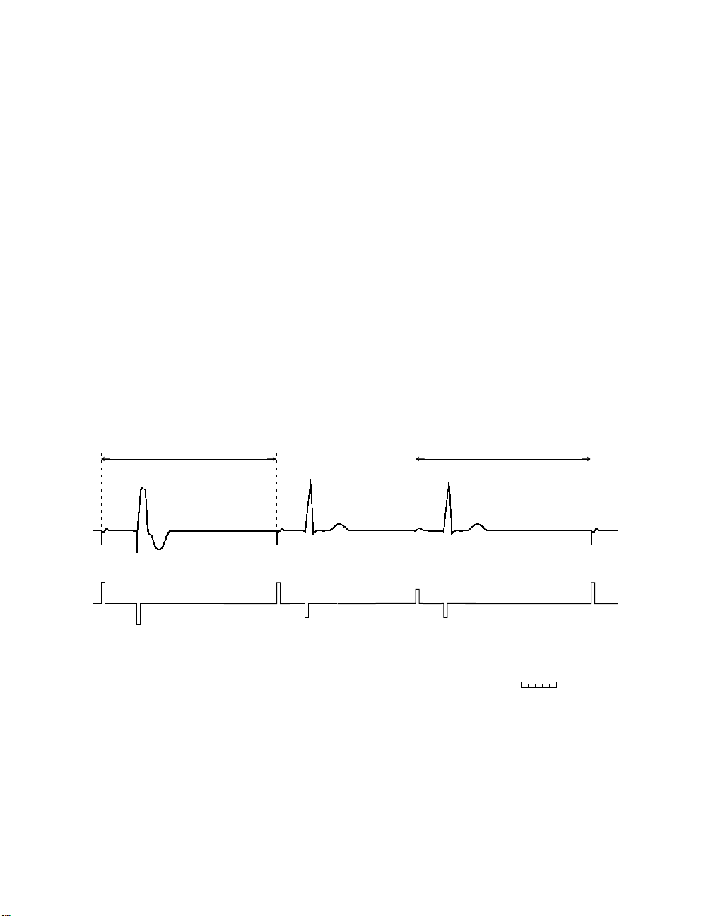
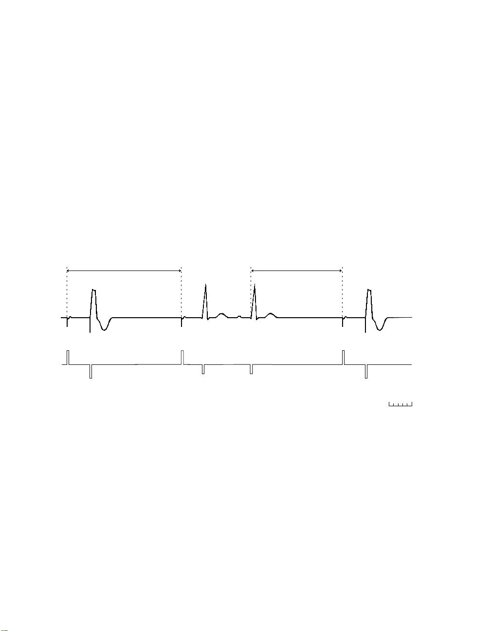
DDDR mode
In the DDDR mode, the pacemaker tracks the faster of the intrinsic atrial
rate or the sensor-indicated rate. If the intrinsic rate is faster, the DDDR
mode provides atrial synchronous pacing; otherwise, AV sequential
pacing occurs at the sensor-indicated rate.
■
Rate limits for atrial tracking (Upper Tracking Rate)1 and sensor
tracking (Upper Sensor Rate) are separately programmable.
■
The AV intervals that follow sensed atrial events (SAV) and paced
atrial events (PAV) are separately programmable, and they can be
programmed to shorten with increasing rates (Rate Adaptive AV) or
to change with intrinsic conduction times (Search AV+).
■
A nonrefractory sensed event in either chamber inhibits pacing in that
chamber. A ventricular nonrefractory sensed event in the VA interval
that is not preceded by an atrial sense (AS or AR) is a pacemakerdefined PVC and starts a new VA interval.
Sensor-indicated
Interval
A
P
V
P
Parameters:
Lower Rate = 60 ppm (1000 ms) PAV Interval = 200 ms PVARP = 280 ms
Sensor-indicated Rate = 90 ppm
(667 ms)
A
P
V
S
SAV Interval = 170 ms
Sensor-indicated
Interval
A
S
V
S
A
P
V
P
Figure 1-3. Example of DDDR mode operation
1
The Total Atrial Refractory Period (TARP) may limit the tracking rate to a lesser value. Refer
to Chapter 3 for more information on TARP.
A
S
V
P
200 ms
EnPulse Pacemaker Reference Guide 1-9
Pacing modes
DDD mode
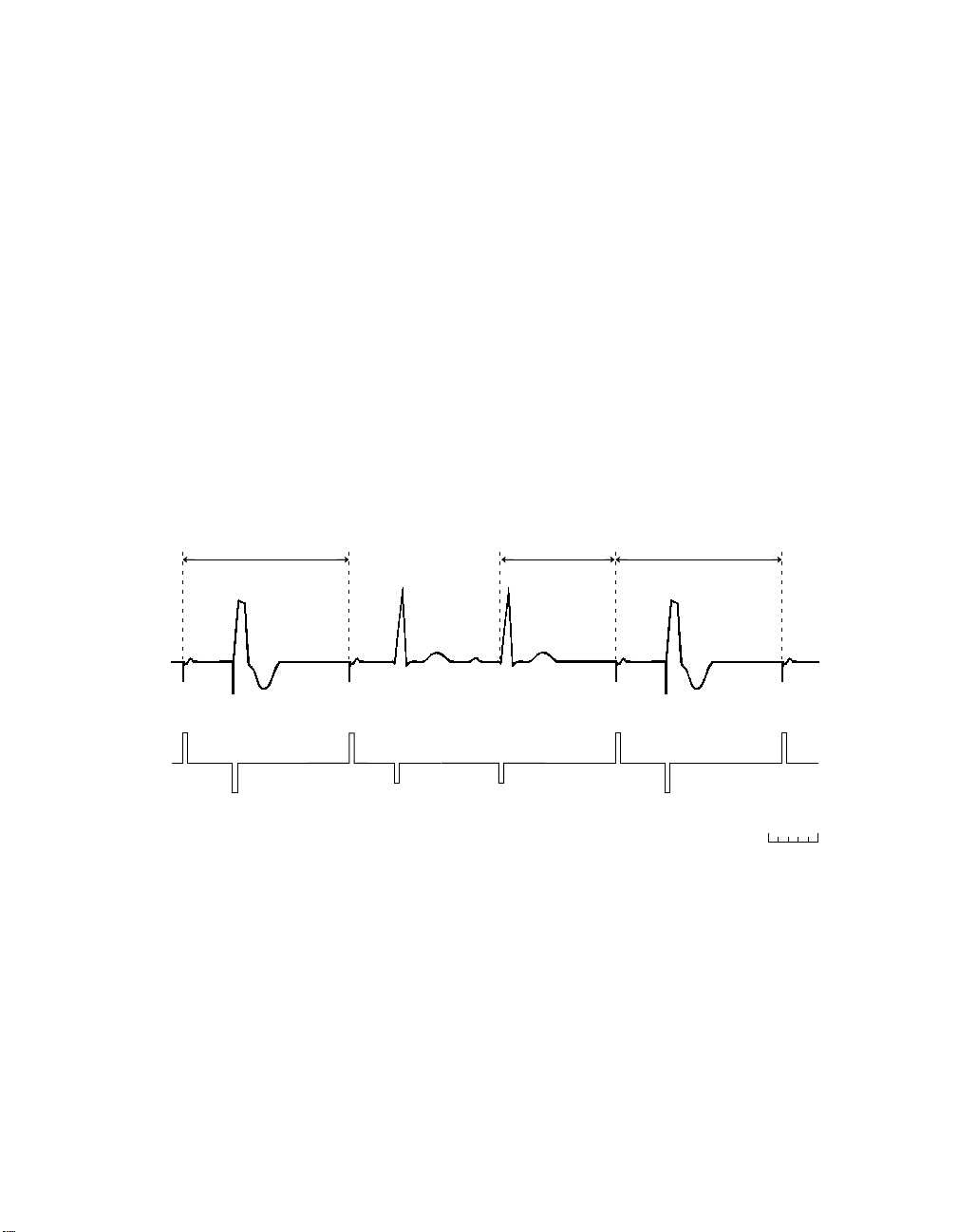
DDD mode
The DDD mode provides atrial synchronous pacing in the presence of
intrinsic atrial activity; otherwise, AV sequential pacing occurs at the
Lower Rate.
■
Each atrial paced or nonrefractory atrial sensed event starts an AV
interval and a lower rate interval. The AV intervals that follow sensed
atrial events (SAV) and paced atrial events (PAV) are separately
programmable, and the SAV may be optionally programmed to
shorten with increasing rate (Rate Adaptive AV) or to change with
intrinsic conduction times (Search AV+).
■
A ventricular paced event may track an atrial sensed event up to the
programmed Upper Tracking Rate.
■
A ventricular nonrefractory sensed event in the VA interval that is not
1
preceded by an atrial sense (AS or AR) is a pacemaker-defined PVC
and starts a new VA interval.
Lower Rate Interval
A
P
V
P
Parameters:
Lower Rate = 60 ppm (1000 ms) PAV Interval = 200 ms
A
P
V
S
SAV Interval = 170 ms
Figure 1-4. Example of DDD mode operation
1
The Total Atrial Refractory Period (TARP) may limit the tracking rate to a lesser value.
Lower Rate Interval
A
S
V
S
A
P
200 ms
1-10 EnPulse Pacemaker Reference Guide
DDIR mode
Pacing modes
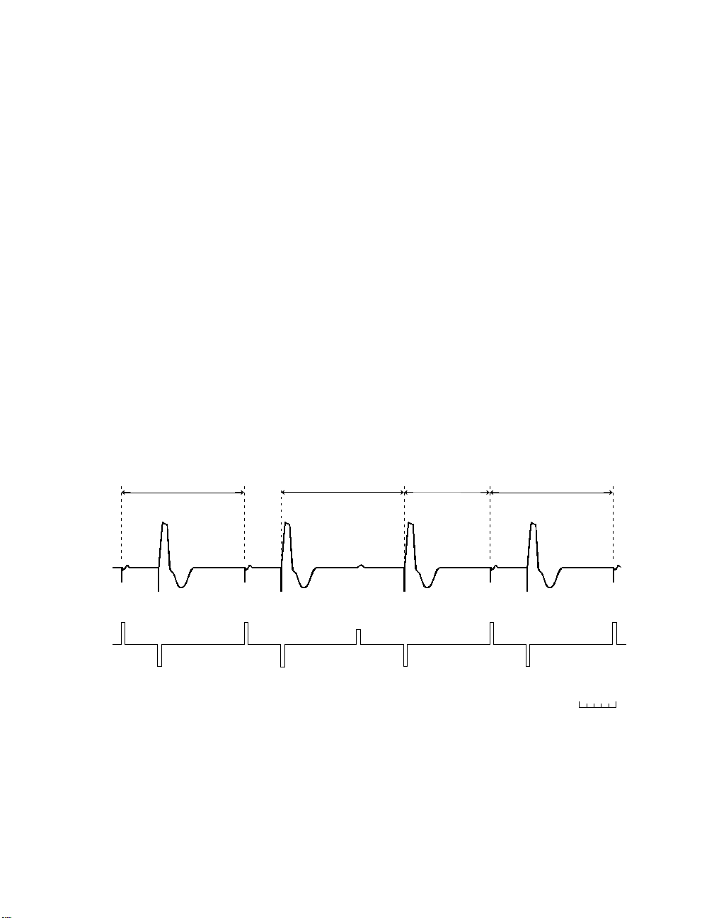
DDIR mode
The DDIR mode provides dual chamber, sensor-driven, atrioventricular
(AV) sequential pacing for heart rate variation without atrial tracking.
■
Atrial pacing occurs at the sensor-indicated rate. If it is not inhibited,
ventricular pacing occurs at the end of the PAV interval.
■
The AV intervals that follow paced atrial events (PAV) are separately
programmable, and they can be programmed to shorten with
increasing rates (Rate Adaptive AV) or to change with intrinsic
conduction times (Search AV+).
■
An atrial event sensed outside the PVARP will inhibit a scheduled
atrial stimulus but will not start an AV interval. That is, ventricular
paced events after such sensed atrial events occur at the sensorindicated rate. The following ventriculoatrial (VA) interval may be
extended slightly to avoid an increasing atrial paced rate.
■
A ventricular nonrefractory sensed event in the VA interval starts a
new VA interval.
Sensor-indicated
Interval
A
P
V
P
Parameters:
Lower Rate = 60 ppm (1000 ms) PAV Interval = 200 ms
Sensor-indicated Rate = 90 ppm (667 ms)
A
P
Sensor-indicated
Interval
V
P
A
S
Sensor-indicated
V
P
Figure 1-5. Example of DDIR mode operation
EnPulse Pacemaker Reference Guide 1-11
VA I n t erv a l
Sensor-indicated
Interval
A
A
P
P
V
P
200 ms
A
P
Pacing modes
DDI mode
DDI mode
The DDI mode provides dual chamber atrioventricular (AV) sequential
pacing with atrial sensing but without atrial tracking.
■
Atrial pacing occurs at the Lower Rate. If it is not inhibited, ventricular
pacing occurs at the end of the PAV interval.
■
The AV intervals that follow paced atrial events (PAV) are separately
programmable, and they can be programmed to change with intrinsic
conduction times (Search AV+).
■
An atrial event sensed outside the PVARP will inhibit a scheduled
atrial stimulus but will not start an AV interval. Ventricular paced
events after such sensed atrial events occur at the Lower Rate.
■
A ventricular nonrefractory sensed event in the ventriculoatrial (VA)
interval starts a new VA interval.
Lower Rate Interval
A
P
V
P
Parameters:
Lower Rate = 60 ppm (1000 ms) PAV Interval = 200 ms
A
P
Lower Rate Interval Lower Rate VA Interval
V
P
Figure 1-6. Example of DDI mode operation
A
S
V
P
200 ms
A
P
1-12 EnPulse Pacemaker Reference Guide
DVIR mode
Pacing modes
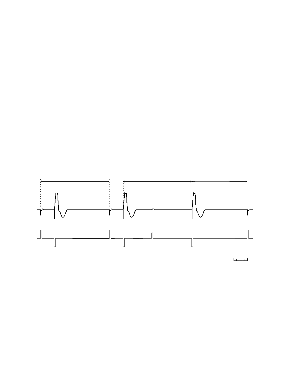
DVIR mode
The DVIR mode provides AV sequential pacing at the sensor-indicated
rate unless inhibited by ventricular sensed events.
■
Atrial pacing occurs at the sensor-indicated rate. If it is not inhibited,
ventricular pacing occurs at the end of the PAV interval.
■
The AV intervals that follow paced atrial events (PAV) are separately
programmable, and they can be programmed to shorten with
increasing rates (Rate Adaptive AV) or to change with intrinsic
conduction times (Search AV+).
■
The DVIR mode ignores intrinsic atrial events. Sensing occurs only in
the ventricle. A ventricular nonrefractory sensed event during the
ventriculoatrial (VA) interval starts a new VA interval.
Sensor-indicated
Interval
A
P
V
P
Parameters:
Lower Rate = 60 ppm (1000 ms) PAV Interval = 200 ms
Sensor-indicated Rate = 90 ppm (667 ms)
A
P
V
S
Sensor-indicated
VA Interval
V
S
Figure 1-7. Example of DVIR mode operation
Sensor-indicated
Interval
A
P
V
P
A
P
200 ms
EnPulse Pacemaker Reference Guide 1-13
Pacing modes
DVI mode
DVI mode
The DVI mode provides dual chamber AV sequential pacing without atrial
sensing/tracking.
■
Atrial pacing occurs at the Lower Rate. If it is not inhibited, ventricular
pacing occurs at the end of the PAV interval.
■
The AV intervals that follow paced atrial events (PAV) are separately
programmable, and they can be programmed to change with intrinsic
conduction times (Search AV+).
■
Sensing occurs only in the ventricle, and intrinsic atrial events are
ignored. A ventricular nonrefractory sensed event during the VA
interval starts a new ventriculoatrial (VA) interval.
Lower Rate Interval
A
P
V
P
Parameters:
Lower Rate = 60 ppm (1000 ms) PAV Interval = 200 ms
A
P
V
S
Figure 1-8. Example of DVI mode operation
Lower Rate VA Interval
V
S
A
P
V
P
200 ms
1-14 EnPulse Pacemaker Reference Guide
 Loading...