

Page 1

EVERA™ DR
Family of digital dual-chamber implantable cardioverter defibrillators
Reference Manual
Caution: Federal law (USA) restricts this device to sale by or on the order of a physician.
Page 2

Page 3

EVERA™ DR
Reference Manual
A reference manual for the Medtronic Evera DR family of digital dual-chamber implantable
cardioverter defibrillators.
Page 4

The following list includes trademarks or registered trademarks of Medtronic in the United
States and possibly in other countries. All other trademarks are the property of their respective
owners.
Active Can, ATP During Charging, Capture Management, Cardiac Compass, CareAlert,
CareLink, ChargeSaver, Conexus, Evera, Export, Flashback, Integrity, Intrinsic,
Marker Channel, Marquis, Medtronic, Medtronic CareAlert, Medtronic CareLink, MVP,
OptiVol, Paceart, PR Logic, Quick Look, Reactive ATP, SessionSync, Switchback, T-Shock,
TherapyGuide
Page 5

Medtronic
EVERA™ DR
Contents
1 Introduction .......................................................... 8
1.1 Introduction ......................................................... 8
1.2 Evera DR ICD feature model matrix .................................... 10
2 Conducting a patient session with the programmer .................... 11
2.1 Establishing telemetry between the device and the programmer ........... 11
2.2 Starting a patient session ............................................ 16
2.3 Display screen features .............................................. 19
2.4 Delivering an emergency tachyarrhythmia therapy ....................... 24
2.5 Enabling emergency VVI pacing ...................................... 26
2.6 Suspending and resuming tachyarrhythmia detection .................... 27
2.7 Monitoring cardiac activity with the Live Rhythm Monitor .................. 29
2.8 Navigating a patient session with Checklist ............................. 38
2.9 Programming device parameters ...................................... 40
2.10 Saving and retrieving a set of parameter values ......................... 43
2.11 Using TherapyGuide to select parameter values ......................... 44
2.12 Storing patient information ........................................... 47
2.13 Printing reports ..................................................... 49
2.14 Transferring data to Paceart with SessionSync .......................... 51
2.15 Saving and retrieving device data ..................................... 58
2.16 Ending a patient session ............................................. 61
2.17 Patient follow-up guidelines ........................................... 61
2.18 Optimizing device longevity ........................................... 65
3 Diagnostic data features ............................................. 70
3.1 Quick Look II summary data .......................................... 70
3.2 Medtronic CareAlert events and notifications ............................ 74
3.3 RV Lead Integrity Alert ............................................... 83
3.4 Device and lead performance data .................................... 90
3.5 OptiVol 2.0 fluid status monitoring ..................................... 99
3.6 Cardiac Compass Trends ........................................... 104
3.7 Heart Failure Management Report .................................... 110
Reference Manual 5
Page 6

Medtronic
3.8 Arrhythmia Episodes data ........................................... 117
3.9 Episode and therapy counters ....................................... 127
3.10 Flashback Memory data ............................................ 132
3.11 Rate Drop Response episodes ....................................... 133
3.12 Rate Histograms ................................................... 136
3.13 Automatic device status monitoring ................................... 138
4 Pacing features ..................................................... 142
4.1 Sensing .......................................................... 142
4.2 Basic pacing ...................................................... 152
4.3 Managed Ventricular Pacing (MVP) ................................... 162
4.4 Rate Response .................................................... 169
4.5 Capture Management .............................................. 176
4.6 Rate Adaptive AV .................................................. 187
4.7 Auto PVARP ...................................................... 189
4.8 Rate Drop Response ............................................... 191
4.9 Rate Hysteresis .................................................... 197
4.10 Sleep feature ...................................................... 199
4.11 Non-Competitive Atrial Pacing ....................................... 200
4.12 PMT Intervention .................................................. 202
4.13 PVC Response .................................................... 203
4.14 Ventricular Safety Pacing ............................................ 205
4.15 Mode Switch ...................................................... 207
4.16 Conducted AF Response ........................................... 210
4.17 Atrial Rate Stabilization ............................................. 212
4.18 Atrial Preference Pacing ............................................ 215
4.19 Post-Mode Switch Overdrive Pacing .................................. 219
4.20 Post Shock Pacing ................................................. 222
4.21 Post VT/VF Shock Overdrive Pacing .................................. 223
4.22 Ventricular Rate Stabilization ........................................ 224
EVERA™ DR
5 Tachyarrhythmia detection features .................................. 227
5.1 AT/AF detection ................................................... 227
5.2 VT/VF detection ................................................... 233
5.3 PR Logic .......................................................... 248
5.4 Wavelet .......................................................... 252
6 Reference Manual
Page 7

Medtronic
5.5 Onset ............................................................ 259
5.6 Stability ........................................................... 265
5.7 High Rate Timeout ................................................. 267
5.8 TWave Discrimination .............................................. 269
5.9 RV Lead Noise Discrimination ....................................... 273
6 Tachyarrhythmia therapy features ................................... 278
6.1 Atrial therapy scheduling ............................................ 278
6.2 Atrial ATP therapies ................................................ 285
6.3 Atrial cardioversion ................................................. 295
6.4 Patient-activated atrial cardioversion .................................. 301
6.5 VF therapies ...................................................... 306
6.6 Ventricular ATP therapies ........................................... 316
6.7 Ventricular cardioversion ............................................ 326
6.8 Progressive Episode Therapies ...................................... 335
7 System test and EP Study features .................................. 337
7.1 Underlying Rhythm Test ............................................. 337
7.2 Pacing Threshold Test .............................................. 338
7.3 Wavelet Test ...................................................... 340
7.4 Lead Impedance Test ............................................... 343
7.5 Sensing Test ...................................................... 344
7.6 Charge/Dump Test ................................................. 346
7.7 Arrhythmia inductions with EP Studies ................................ 347
7.8 Manual therapies with EP Studies .................................... 355
EVERA™ DR
Glossary ................................................................ 358
Index ................................................................... 368
Reference Manual 7
Page 8

Medtronic
EVERA™ DR
1 Introduction
1.1 Introduction
This manual describes the operation and intended use of features offered by Medtronic
Evera DR ICD devices.
Throughout this manual, the word “device” refers to the implanted DR ICD device.
The programmer screen image examples in this manual are provided for reference only and
may not match the final software.
The names of on-screen buttons are shown within brackets: [Button Name].
Tables in the feature programming sections summarize how to navigate to screens with
programmable parameters for the feature. As shown in the example in Table 1, each table
row lists a parameter or group of parameters with the path to a specific screen on the
programmer. If the navigation path is the same for related parameters, the path is not
repeated in the table. Additional rows are included for parameters that appear on different
screens. Groups of parameters, such as “ATP parameters”, include the word “parameters”.
Individual parameters, such as “Energy” and “Pathway”, do not.
Table 1. How to navigate to VF therapies parameters
Parameters Path
VF therapies (Rx1 through Rx6)
VF Therapy Status (On, Off)
Energy
Pathway
ATP parameters (Rx1) Params > VF Therapies… > ATP…
ChargeSaver parameters (ATP in Rx1) Params > VF Therapies… > ATP… > During
Shared Settings (V. ATP and V. Therapies) Params > VF Therapies… > Shared Settings…
Params > VF Therapies…
Charging > ChargeSaver…
The feature programming sections also include programming considerations. For detailed
information about parameter settings, see the device manual for the specific device.
1.1.1 Product literature
Before implanting the device, it is recommended that you take the following actions:
●
Read the product literature for information about prescribing, implanting, and using the
device and conducting a patient follow-up session.
8 Reference Manual
Page 9

Medtronic
●
Thoroughly read the technical manuals for the leads used with the device. Also read the
EVERA™ DR
technical manuals for other system components.
●
Discuss the device and implant procedure with the patient and any other interested
parties, and give them any patient information materials packaged with the device.
The following manuals and documents also contain information about the device:
Device manual – Each device model has a separate device manual. The manual contains
the specific features for the model, indications and contraindications, warnings and
precautions, instructions for implanting the device, quick reference specifications, and
parameter tables.
Explanation of symbols – This document defines the symbols that may appear on the
device package. Refer to the package label to see which symbols apply specifically to this
device.
Radio regulatory compliance information – This document provides compliance
information related to radio components of the device.
Medical Procedure and EMI Warnings and Precautions Manual for Health Care
Professionals – This manual provides warnings, precautions, and guidance for health care
professionals who perform medical therapies and diagnostic procedures on cardiac device
patients. The manual also provides patient education information related to sources of
electromagnetic interference (EMI) at home, at work, and in other environments.
1.1.2 Technical support
Medtronic employs highly trained representatives and engineers located throughout the
world to serve you and, upon request, to provide training to qualified hospital personnel in the
use of Medtronic products.
In addition, Medtronic maintains a professional staff of consultants to provide technical
consultation to product users.
For more information, contact your local Medtronic representative or call or write Medtronic
at the appropriate telephone number or address listed on the back cover.
Reference Manual 9
Page 10

Medtronic
EVERA™ DR
1.1.3 Notice
The Patient Information screen of the programmer software application is provided as an
informational tool for the end user. The user is responsible for accurate input of patient
information into the software. Medtronic makes no representation as to the accuracy or
completeness of the patient information that end users enter into the Patient Information
screen. Medtronic SHALL NOT BE LIABLE FOR ANY DIRECT, INDIRECT, INCIDENTAL,
OR CONSEQUENTIAL DAMAGES TO ANY THIRD PARTY THAT RESULT FROM THE
USE OF THE PATIENT INFORMATION SUPPLIED BY END USERS TO THE SOFTWARE.
For more information, see Section 2.12, “Storing patient information”, page 47.
1.2 Evera DR ICD feature model matrix
Feature availability for each device model is marked with an “X” in the corresponding column.
Table 2. Product feature relationship
Evera XT DR Evera S DR
DDBB1D1
Features
Optivol 2.0 fluid status monitoring X
Heart Failure Management Report X
DDBB1D4
DDBC3D1
DDBC3D4
Note: All other features described in this manual apply to all Evera DR ICD devices.
10 Reference Manual
Page 11

Medtronic EVERA™ DR
2 Conducting a patient session with the programmer
2.1 Establishing telemetry between the device and the programmer
You can conduct a patient session using wireless or nonwireless telemetry.
You cannot switch between wireless and nonwireless telemetry during a patient session. If
you are conducting a patient session and you wish to change the telemetry mode, you must
end that session and start a new session using the alternative mode.
Refer to the programmer reference guide for information about setting up the programmer for
a patient session.
2.1.1 Using Conexus wireless telemetry
To establish wireless telemetry, use a Medtronic programmer with Conexus telemetry or a
Medtronic Conexus activator. A Medtronic Conexus activator is a hand-held,
battery-powered communication device. It enables wireless telemetry in a
Conexus-compatible heart device independently of a programmer. Once wireless telemetry
is established, a practitioner can use the programmer to conduct a session without using the
programming head.
Conexus wireless telemetry uses the Medical Implant Communications Service (MICS)
radiofrequency band, which is designated worldwide for medical devices. Using this band
protects devices against interference from home electronics, such as microwaves, cell
phones, and baby monitors.
Conexus wireless telemetry is designed for use during implant and follow-up sessions.
At implant, Conexus wireless telemetry enables you to:
●
Interrogate the patient’s wireless device without using a programming head (no
programming head in the sterile field)
●
Maintain connectivity during induction and delivery of therapies
●
Program the device anytime during the procedure while maintaining continuous patient
monitoring
1
1
Medical Implant Communications Service (MICS) is also referred to as the core 402-405 MHz band of the
Medical Device Radiocommunication Service (MedRadio).
Reference Manual 11
Page 12
Medtronic
During follow-up sessions, Conexus wireless telemetry maintains continuous
communication between the device and the programmer.
During remote follow-up sessions with the CareLink Network, Conexus wireless telemetry
automatically transmits comprehensive arrhythmia and diagnostic device data. It transmits
wirelessly without patient involvement.
EVERA™ DR
2.1.1.1 How to activate wireless telemetry
1. Turn on the programmer.
Make sure the “Allow wireless communication” check box in the Find Patient window is
selected.
2. Use the Conexus Activator, or briefly place the programming head over the device to
activate wireless telemetry in the device.
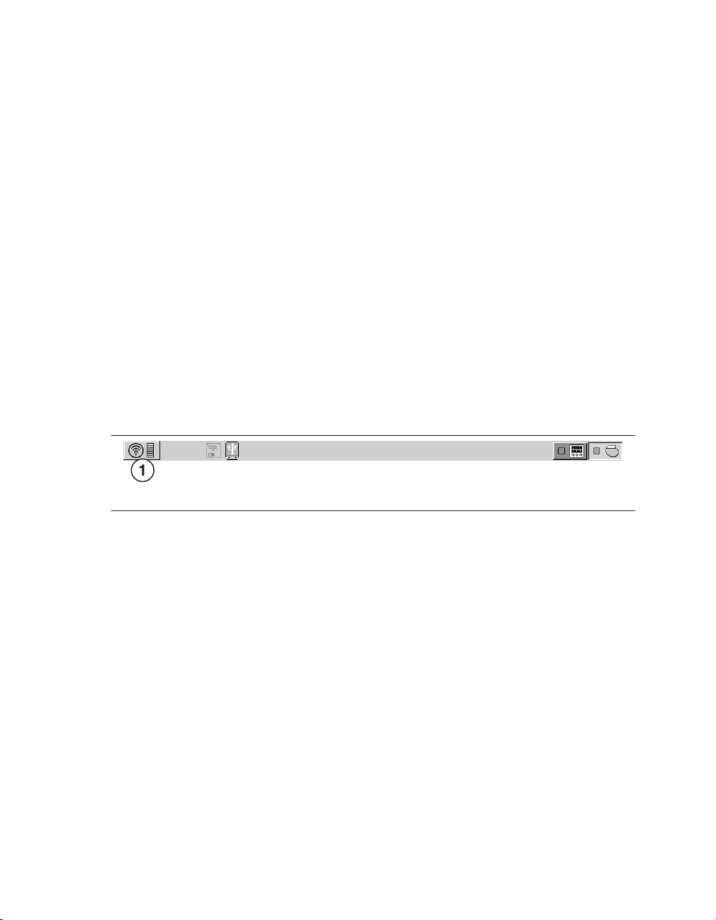
When wireless telemetry is first established during a session, the telemetry status
indicator in the upper left corner of the task bar changes from the programming head
icon to the wireless telemetry icon, as shown in Figure 1 .
Figure 1. Wireless telemetry icon on the task bar
1 Wireless telemetry icon
The indicator bar on the icon displays the strength of the wireless signal. At least 3 of the
green lights must be illuminated to ensure reliable telemetry has been established.
If you are using the Conexus Activator, press the blue button to activate wireless
telemetry. A green light illuminates when you have successfully communicated with the
device.
2.1.1.2 Conexus wireless timer operation
Once you initiate wireless telemetry, the device sends a signal to the programmer and
remains active for a period of time. A response from the programmer establishes
communication, and the device appears in the Find Patient window when that window is
open. If the programmer touch pen is not used within 5 min, the Find Patient window closes
and the Select Model screen appears.
When you end a session, you have a short period of time where you can re-interrogate the
device before the session ends completely.
12 Reference Manual
Page 13

Medtronic
EVERA™ DR
The inactivity timer is 2 hours for the first week after implant, at which time it changes to 5 min
automatically. If the Extend Wireless Telemetry Session feature is available, you have the
option to extend the inactivity timer from 5 min to 2 hours in any patient session. When the
session is ended, the timer reverts to 5 min. This feature reduces device battery depletion.
If electrical interference disrupts a session, the programmer attempts to re-establish
communication with the device. If you are unable to re-establish communication between the
device and the programmer, use the Conexus Activator or programming head to reactivate
wireless telemetry in the device to resume or start a session.
2.1.1.3 How to maintain reliable telemetry
You can expect reliable wireless telemetry between the implanted device and the
programmer in a typical examination room or operating room. If other electrical equipment is
in the area, the system is designed to maintain effective communication between the device
and the programmer at distances up to 2 m (6.5 feet). The system should not interfere with
other electronic equipment in the area.
If you are having trouble maintaining consistent, reliable telemetry, take one or more of the
following actions:
●
Adjust the angle of the programmer screen. The telemetry antenna is part of the
programmer display screen structure; slight movements of the screen may improve the
telemetry link.
●
Change the position of the programmer so that the space between the programmer
screen and the patient is relatively free of obstruction. Make sure that nothing is between
the programmer and the patient.
●
Shorten the distance between the programmer and the patient.
●
Remove any sources of electromagnetic interference (EMI) that may be affecting the
telemetry signal.
2.1.1.4 Session inactivity safeguards
If you or the patient moves away from the programmer, the system guards against
unintentional programming in the following ways:
●
After 2 min of programmer inactivity, the system displays the patient’s name or ID
number, if available, and device information. You are then required to confirm that the
correct patient is in the follow-up session before you can process a programming
command.
Reference Manual 13
Page 14

Medtronic
●
The device transitions to Standby mode after a period of programmer inactivity in an
EVERA™ DR
implant session or a follow-up session, as follows:
– At implant and in the first 7 days after implant: The device transitions to Standby mode
after 2 hours of programmer inactivity.
– 7 days after implant: The device transitions to Standby mode after 5 min of
programmer inactivity.
Note: If the Extend Wireless Telemetry Session feature is available, you can
optionally extend the wireless telemetry session to 2 hours, select Session > Extend
Wireless Telemetry Session and select [Continue]. When the session is ended, the
timer reverts to 5 min.
2.1.1.5 Device standby mode
When the device is in standby mode, live waveforms are turned off, the programmer
telemetry status indicator shows no telemetry link, and programmer functions are limited.
You can use standby mode when you need a period of inactivity in a patient session.
To activate and deactivate Standby mode in the device manually:
●
To activate Standby mode, select the wireless telemetry icon on the task bar.
●
To deactivate Standby mode and reactivate wireless telemetry with the programmer,
select the wireless telemetry icon on the task bar or place either the Conexus Activator
or the programming head over the device.
After a brief period of time in Standby mode, wireless telemetry is deactivated within the
device. To recover the wireless telemetry session, use either the Conexus Activator or the
programming head.
Standby mode is also deactivated when you attempt to program parameters, interrogate the
device, or conduct testing or emergency operations. The programmer screen displays the
Verify Patient warning. To deactivate Standby mode and resume a patient session, verify that
the session is with the intended patient, select the “Allow communication with” check box,
and select [Continue].
Note: To use Holter telemetry to transmit EGM and Marker Channel data during a Conexus
telemetry session, you first must activate Standby mode.
14 Reference Manual
Page 15

Medtronic
EVERA™ DR
2.1.1.6 How to maintain patient safety and privacy
During a wireless telemetry session, all other programmers are blocked from
communicating or initiating a session with the patient’s implanted device. Implanted devices
in other patients are locked out from any communication or programming occurring during
the patient’s session.
When you are using wireless telemetry, the patient’s name is displayed on the Command bar
of the programmer screen. If you have not entered the patient’s name, the patient’s ID
number appears. If the patient’s name or ID has not been entered, then “Patient name is not
entered” appears on the Command bar. Enter the patient’s name and ID number as early as
possible to assist with patient identification when using wireless telemetry.
2.1.2 Using nonwireless telemetry
Some Medtronic programmers feature only nonwireless telemetry. If your Medtronic
programmer features both Conexus wireless telemetry and nonwireless telemetry, you must
choose to use nonwireless telemetry.
You must have a Medtronic programming head to use nonwireless telemetry.
2.1.2.1 How to establish nonwireless telemetry
1. Turn on the programmer.
If you are using a programmer with Conexus wireless telemetry, make sure the “Allow
wireless communication” check box in the Find Patient window is not selected. The
check box does not appear if you are using a programmer without Conexus wireless
telemetry.
2. Place the programming head over the device to activate nonwireless telemetry in the
device.
When nonwireless telemetry is established during a session, the telemetry status
indicator on the task bar displays the programming head icon, as shown in Figure 2.
Figure 2. Programming head icon on the task bar
1 Programming head icon
Note: The magnet in the programming head can suspend tachyarrhythmia detection.
However, when telemetry between the device and the programmer is established, detection
is not suspended.
Reference Manual 15
Page 16

Medtronic
When telemetry is established, the amber light on the programming head turns off, and 1 or
more of the green indicator lights on the programming head illuminate. To ensure that the
proper telemetry is established, position the programming head over the device so at least
2 of the green lights illuminate. If the programming head slides off the patient, the session
does not terminate. Place the programming head back over the device to resume
programming or interrogating the device.
Note: More information about the general use of the programming head is available in the
programmer reference guide.
EVERA™ DR
2.2 Starting a patient session
The programmer interrogates the patient’s device at the start of a patient session. Because
the programmer collects and stores data on a session-by-session basis, start a new session
for each patient. End the previous session before starting a session with another patient.
Caution: A programmer failure (for example, a faulty touch pen) could result in inappropriate
programming or the inability to terminate an action or an activity in process. In the event of a
programmer failure, immediately turn the programmer power off to deactivate telemetry and
terminate any programmer-controlled activity in process.
Caution: During a wireless telemetry session, verify that you have selected the appropriate
patient before proceeding with the session, and maintain visual contact with the patient for
the duration of the session. If you select the wrong patient and continue with the session, you
may inadvertently program the wrong patient’s device.
Caution: Do not leave the programmer unattended while a wireless telemetry session is in
progress. Maintain control of the programmer during the session to prevent inadvertent
communication with the patient’s device.
Note: During an initial interrogation, only Emergency programmer functions are available.
2.2.1 How to start a patient session using wireless telemetry
1. Select [Find Patient…] from the Select Model window.
2. Select the “Allow wireless communication” check box on the Find Patient window.
3. Use the Conexus Activator, or briefly place the programming head over the device to
activate wireless telemetry in the device.
16 Reference Manual
Page 17

Medtronic
EVERA™ DR
Notes:
●
When the Conexus Activator is used to activate telemetry in the device, the
programmer launches the patient session without suspending tachyarrhythmia
detection. Placing a magnet near the device, however, suspends tachyarrhythmia
detection.
●
When the programming head is used to activate telemetry in the device, the
programmer automatically launches the patient session with tachyarrhythmia
detection suspended. Detection remains suspended as long as the programming
head is over the device. If tachyarrhythmia detection is programmed on, a warning
reminds you that tachyarrhythmia detection is suspended.
4. Select the appropriate patient from the Patient Name list on the Find Patient window.
Note: The programmer lists all patients with wireless-activated implantable devices
within telemetry range.
5. Select [Start].
2.2.2 How to start a patient session using nonwireless telemetry
1. Select [Find Patient…] from the Select Model window.
2. If you are using a Medtronic programmer with Conexus wireless telemetry, make sure
that the “Allow wireless communication” check box on the Find Patient window is not
selected. If you start a session with the programming head over the patient’s device and
the “Allow wireless communication” check box is selected, the system initiates a
wireless telemetry session and automatically interrogates the device. If you are using a
Medtronic programmer without Conexus wireless telemetry, the “Allow wireless
communication” check box does not appear on the Find Patient window.
3. Place the programming head over the device and the nonwireless session
automatically begins.
2.2.3 Device and telemetry effects during a patient session
Tachyarrhythmia detection during a wireless telemetry session – If you place a
programming head over the device, the magnet in the programming head always suspends
tachyarrhythmia detection.
Tachyarrhythmia detection during a nonwireless telemetry session – If you place a
programming head over the device and telemetry is established, the magnet in the
programming head does not suspend tachyarrhythmia detection.
Reference Manual 17
Page 18

Medtronic
Episodes in progress during a wireless telemetry session – If you attempt to initiate a
patient session when a detected arrhythmia episode is in progress, the device treats the
arrhythmia normally. If telemetry has not been established, the magnet inside the
programming head causes the device to suspend detection when the programming head is
placed over the device.
Episodes in progress during a nonwireless telemetry session – After telemetry has
been established and you position the programming head over the device when a detected
arrhythmia episode is in progress, the device treats the arrhythmia normally. If telemetry has
not been established and you position the programming head over the device, the magnet
inside the programming head causes the device to suspend detection.
Capacitor charging during a wireless telemetry session – Interference caused by
capacitor charging may affect telemetry between the device and the programmer. This
interference could result in a temporary loss of telemetry indicator lights as shown on the
programmer task bar and a temporary loss in Marker transmissions. It could also temporarily
affect the ability to send programming commands. Ensure that the greatest number of
telemetry strength indicator lights are illuminated on the programmer task bar to help
improve telemetry reliability before any manual or automatic capacitor charging.
Capacitor charging during a nonwireless telemetry session – Interference caused by
capacitor charging may affect telemetry between the device and the programmer. The
programming head indicator lights may turn off during charging periods. It is normal for the
lights to turn off on the programming head.
EVERA™ DR
Note: The programming head “P” button is disabled during all EP study and manual system
tests. During tachyarrhythmia inductions, the programming head “I” button is also disabled.
Marker transmissions during a wireless telemetry session – The device continuously
transmits Marker Channel and supplementary marker data while telemetry is established.
The device stops these transmissions when telemetry is interrupted. If Holter telemetry is
programmed to On, the device transmits telemetry at all times except during a Conexus
wireless telemetry session. To use Holter telemetry during a Conexus wireless telemetry
session, you must first activate Standby mode.
Marker transmissions during a nonwireless telemetry session – The device
continuously transmits Marker Channel and supplementary marker data while telemetry is
established and the programming head is positioned over the device. The device stops
these transmissions when you lift the programming head, unless the Holter Telemetry
feature is programmed to On. If Holter Telemetry is programmed to On, the device transmits
Marker Channel and supplementary marker data regardless of the position of the
programming head.
Device longevity and wireless telemetry – In typical patient session and device operation
scenarios, wireless telemetry has no significant effect on device longevity.
18 Reference Manual
Page 19

Medtronic
EVERA™ DR
2.2.4 How to interrogate the device during the session
At the start of the patient session, the programmer interrogates the device. You can manually
interrogate the device at any time during the patient session by performing the following
steps:
1. Select [Interrogate…] from the Command bar. In a nonwireless session, you can also
interrogate the device by pressing the “I” button on the programming head.
2. To gather information collected since the last patient session, select the Since Last
Session option from the interrogation window. To gather all of the information from the
device, select the All option.
3. Select [Start].
Note: You cannot manually interrogate the device during an emergency programmer
operation. You must select [Exit Emergency] before you can manually interrogate the device.
2.3 Display screen features
The programmer display screen is an interface that displays text and graphics. It is also a
control panel that displays buttons and menu options that you can select by using the touch
pen.
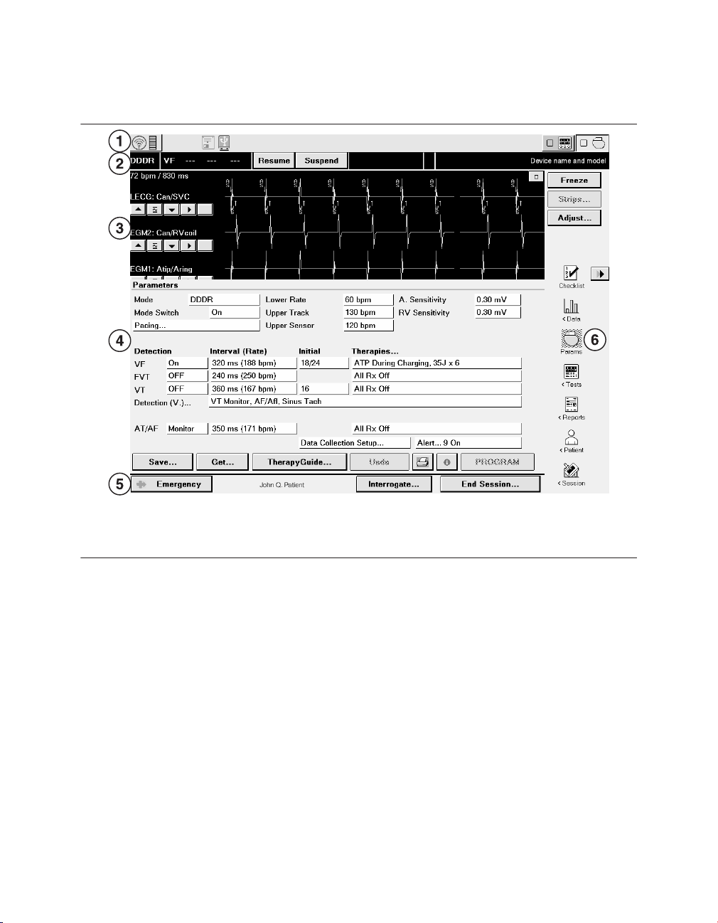
The main elements of a typical display screen during a patient session are shown in
Figure 3.
Reference Manual 19
Page 20
Medtronic
Figure 3. Main elements of a display screen
EVERA™ DR
1 Task bar
2 Status bar
3 Live Rhythm Monitor window
4 Task area
5 Command bar
6 Tool palette
If the SessionSync feature is installed on the programmer, the programmer task bar displays
an icon that indicates the status of the SessionSync feature. For complete information on
viewing the status of the SessionSync feature from the programmer task bar, see
Section 2.14, “Transferring data to Paceart with SessionSync”, page 51.
2.3.1 Task bar
The display screen features a task bar at the top of the screen. You can use the task bar to
note the status of programmer-specific features such as the analyzer.
The task bar also includes a graphical representation of the telemetry strength indicator. In
a wireless telemetry session, selecting the wireless telemetry icon breaks the telemetry link.
Selecting it again restores the telemetry link. If you are conducting a nonwireless telemetry
session, the task bar includes a graphical representation of the telemetry strength light array
on the programming head.
20 Reference Manual
Page 21
1 2 3 4 6
5
Medtronic
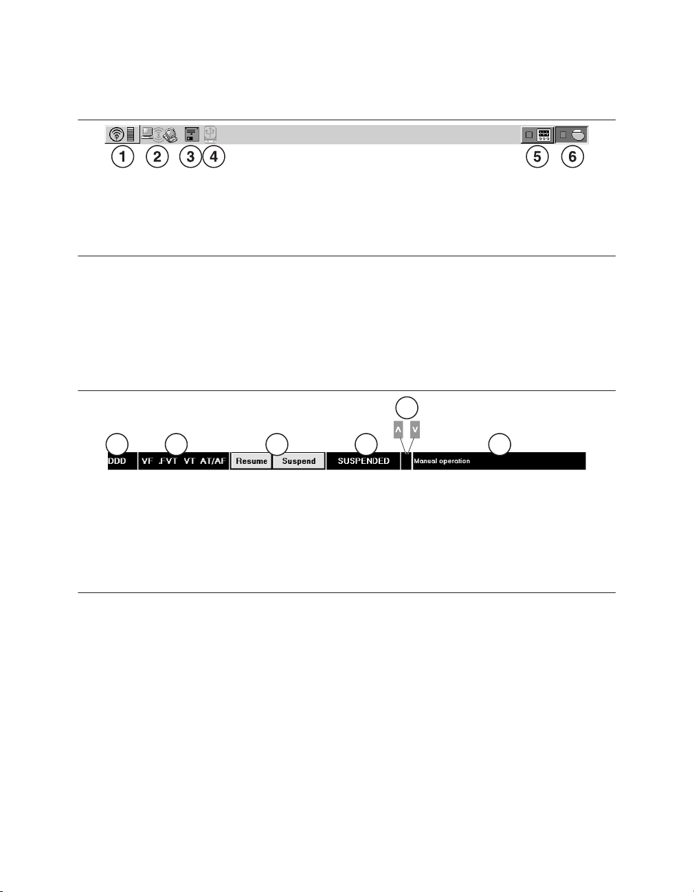
Figure 4. Task bar display
EVERA™ DR
1 Telemetry icon and telemetry strength
indicator (wireless telemetry shown)
2 SessionSync icon
3 Disk icon (for some Medtronic programmer
models)
4 USB icon
5 Analyzer icon
6 Device icon
2.3.2 Status bar
When the device has been interrogated, you can use the status bar at the top of the display
screen (located immediately below the task bar) to perform some basic functions and to note
the current status of the device.
Figure 5. Status bar display
1 Currently active pacing mode
2 Programmed detection and therapy configuration
3 Buttons used to resume or suspend detection
4 Automatic detection status
5 Indicator that a tachyarrhythmia episode is in progress
6 Either the current episode, therapy, or manual operation status, or the device name and model
number
2.3.3 Live Rhythm Monitor window
The Live Rhythm Monitor window displays ECG, Leadless ECG, Marker Channel, and
telemetered EGM waveform traces. In addition to waveform traces, the Live Rhythm Monitor
window shows the following information:
●
The heart rate and the rate interval appear if telemetry has been established with the
device.
●
The annotations above the waveform trace show the point at which parameters are
programmed.
Reference Manual 21
Page 22
Medtronic
The Live Rhythm Monitor window appears in the partial view by default. You can expand this
window to its full size by selecting the small square button in the upper right corner of the
window or by selecting [Adjust…]. For more information, see Section 2.7, “Monitoring
cardiac activity with the Live Rhythm Monitor”, page 29 .
EVERA™ DR
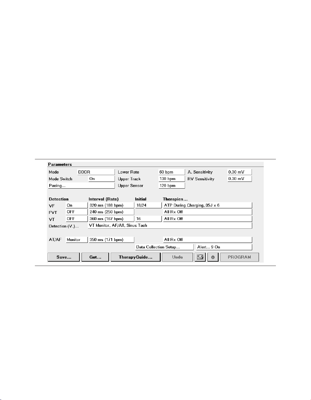
2.3.4 Task area
The portion of the screen between the Live Rhythm Monitor window near the top of the
screen and the command bar at the bottom of the screen changes according to the task or
function you select.
One example of a task area is the Parameters screen, which is used to view and program
device parameters as described in Section 2.9, “Programming device parameters”,
page 40.
Figure 6. Task area of the screen
2.3.5 Tool palette
The buttons and icons along the right edge of the screen are referred to as the “tool palette”.
You can use these tools to display a task or function screen. After starting a patient session,
the tool palette is displayed on all but the Emergency or Live Rhythm Monitor Adjust…
screens, making it quick and easy to move to the desired task or function.
Each of the icons acts like a button. To select an icon, touch the icon with the touch pen. Each
option in the tool palette is described in Table 3.
22 Reference Manual
Page 23
Medtronic
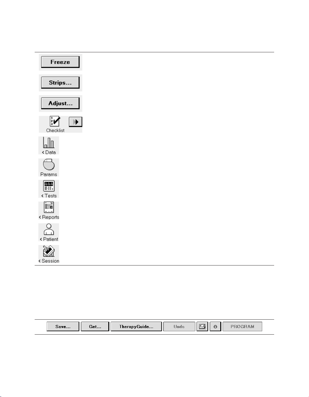
Table 3. Tool palette options
The [Freeze] button captures a segment of the Live Rhythm Monitor display.
The [Strips…] button accesses the waveform strips saved since the start
of the session.
The [Adjust…] button opens a window of options for adjusting the Live
Rhythm Monitor display.
The Checklist icon opens the Checklist screen for simplified navigation
through a set of follow-up tasks. The Checklist [>>] button navigates to the
next task in the Checklist.
The Data icon displays options for viewing device information and diagnostic data.
The Params icon displays the Parameters screen for viewing and programming device parameters.
The Tests icon displays options for performing system tests and EP studies.
EVERA™ DR
The Reports icon displays options for printing reports.
The Patient icon displays options for accessing the TherapyGuide screen
or the Patient Information screen.
The Session icon displays options for adjusting preferences, viewing
parameter changes made during the session, saving data, and ending the
session.
2.3.6 Buttons
Buttons, such as those shown in Figure 7, respond when you “select” them by touching them
with the tip of the touch pen.
Figure 7. Display screen buttons
Buttons with a less distinctly shaded label are inactive and do not respond if you select them.
Reference Manual 23
Page 24

Medtronic
EVERA™ DR
Selecting a button with the touch pen causes one of the following responses:
●
Buttons such as the [PROGRAM] button execute a command directly.
●
Buttons such as the [Save…] and [Get…] buttons open a window that prompts another
action. The labels on these buttons end with an ellipsis.
A procedure may instruct you to “press and hold” a button. In such cases, touch the tip of the
touch pen to the button and continue to maintain pressure against the button. The button
continues to respond to the touch pen until you remove the touch pen from the button.
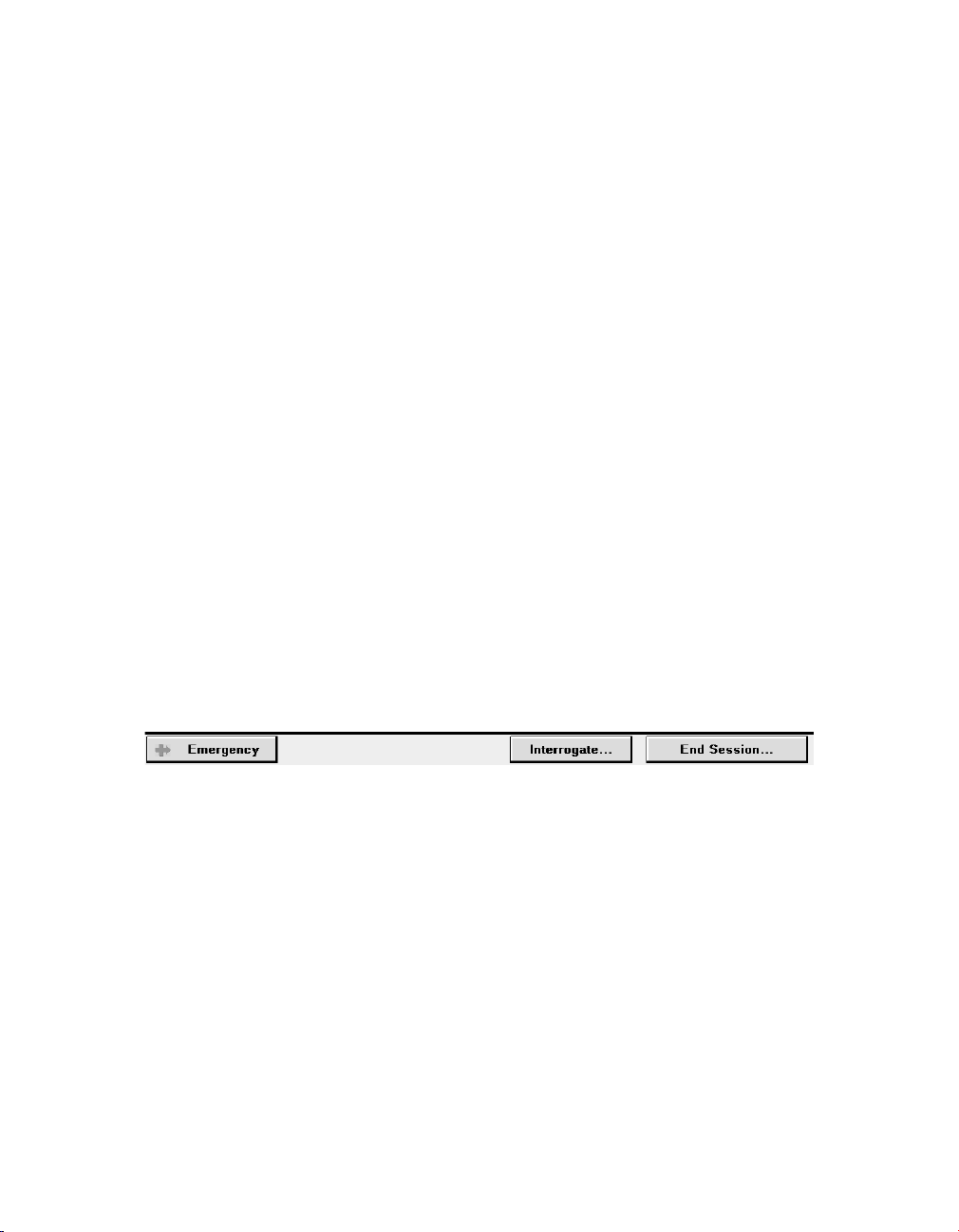
2.3.7 Command bar
The bar at the bottom of the screen always shows the buttons for programming Emergency
parameters, interrogating the device, and ending the patient session.
If the programmer is using wireless telemetry, the patient may be identified on the command
bar of the programmer screen. Depending on the programmed patient information, one of
the following text fields appears:
●
the patient name
●
the patient ID, if the patient name was not entered
●
the message “(Patient name not entered)”, if neither the name nor the ID was entered
Note: The [Interrogate…] and [End Session…] buttons do not appear on the Emergency
screen.
Figure 8. Command bar
2.4 Delivering an emergency tachyarrhythmia therapy
You can use emergency defibrillation, cardioversion, and fixed burst pacing therapies to
quickly treat ventricular tachyarrhythmia episodes during a patient session. Emergency
defibrillation therapy delivers a high-voltage biphasic shock at the selected energy level.
Emergency cardioversion therapy also delivers a high-voltage biphasic shock, but it must be
synchronized to a ventricular event. Emergency fixed burst pacing therapy delivers
maximum output pacing pulses to the ventricle at the selected interval.
24 Reference Manual
Page 25
Medtronic
EVERA™ DR
2.4.1 Considerations for emergency tachyarrhythmia therapies
Tachyarrhythmia detection during emergency tachyarrhythmia therapies – The
device suspends the tachyarrhythmia detection features when emergency defibrillation,
cardioversion, or fixed burst pacing therapies are delivered. Select [Resume] to re-enable
tachyarrhythmia detection.
Temporary parameter values – Emergency tachyarrhythmia therapies use temporary
parameter values that do not change the programmed parameters of the device. After the
tachyarrhythmia therapy is complete, the device reverts to its programmed parameter
values.
Aborting an emergency tachyarrhythmia therapy – You can immediately terminate an
emergency defibrillation or emergency cardioversion therapy by selecting [ABORT]. To stop
an emergency fixed burst therapy, remove the touch pen from [BURST Press and Hold].
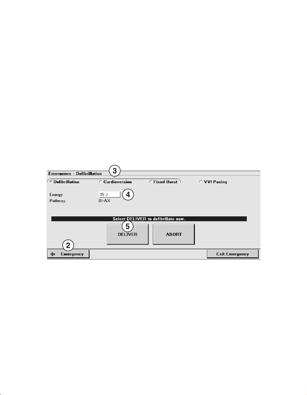
2.4.2 How to deliver an emergency tachyarrhythmia therapy
1. Establish telemetry with the device.
2. Select [Emergency].
3. Select the type of emergency therapy to deliver: Defibrillation, Cardioversion, or Fixed
Burst.
4. Accept the therapy parameters shown on the screen, or select new values.
5. For defibrillation and cardioversion therapy, select [DELIVER]. For fixed burst therapy,
select [BURST Press and Hold] and hold the touch pen over the button for as long as
you want to deliver the therapy.
Reference Manual 25
Page 26
Medtronic
EVERA™ DR
2.5 Enabling emergency VVI pacing
You can use emergency VVI pacing to quickly enable 70 bpm, high-output ventricular pacing
to restore ventricular support in an emergency situation.
2.5.1 Considerations for emergency VVI pacing
Parameter values – Emergency VVI pacing reprograms pacing parameters to emergency
settings. For a list of the emergency VVI parameter settings, see the device manual for the
device. To terminate emergency VVI pacing, you must reprogram pacing parameters from
the Parameters screen.
2.5.2 How to enable emergency VVI pacing
1. During a patient session, establish telemetry with the device.
2. Press the red VVI button on the programmer to enable emergency VVI pacing.
Depending on your model of Medtronic programmer, the emergency VVI button is:
●
a mechanical red button to the left of the programmer screen, on the programmer
bezel.
●
a red button on the programmer button panel, above the programmer screen.
Note: On all programmers, an [Emergency] button is implemented in the software and is
available on the display screen (see the following procedure for instructions regarding this
button).
How to enable emergency VVI pacing with the on-screen [Emergency] button –
Perform the following steps to enable emergency VVI pacing with the on-screen
[Emergency] button:
26 Reference Manual
Page 27
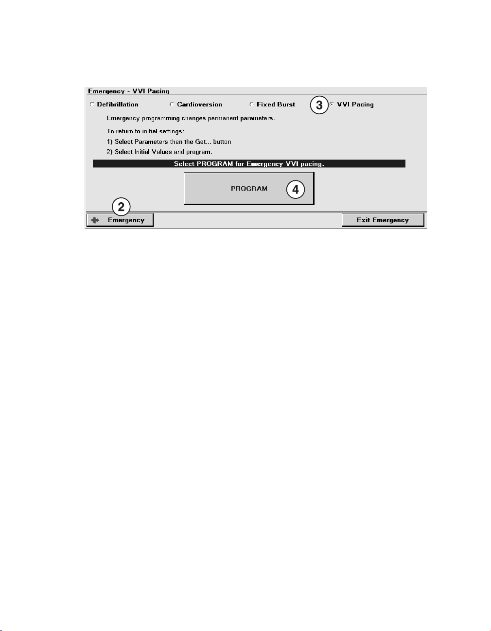
Medtronic
1. Establish telemetry with the device.
2. Select [Emergency].
3. Select VVI Pacing.
4. Select [PROGRAM].
EVERA™ DR
2.6 Suspending and resuming tachyarrhythmia detection
It may be necessary to turn off tachyarrhythmia detection in some situations. For example,
during emergency therapies and some EP study tests, therapies are delivered manually, and
detection and episode storage are not needed. Also, certain types of surgery, including
electrocautery surgery, RF ablation, and lithotripsy, can cause the device to detect
tachyarrhythmias inappropriately and possibly deliver inappropriate therapy.
When detection is suspended, the device temporarily stops the process of classifying
intervals for tachyarrhythmia detection. Sensing and bradycardia pacing remain active, and
the programmed detection settings are not modified. When the device resumes detection,
it does so at the previously programmed detection settings. The Suspend/Resume function
applies to both atrial and ventricular tachyarrhythmia detection.
2.6.1 Considerations for suspending detection
If you suspend detection during a tachyarrhythmia detection process but before detection
has occurred, the initial detection never occurs. When you resume, detection starts over.
If you suspend detection after a tachyarrhythmia detection has occurred and resume
detection before the tachyarrhythmia episode terminates, redetection works differently for
each type of episode, as follows:
Reference Manual 27
Page 28

Medtronic
AT/AF episodes – If you suspend detection during a detected AT/AF episode and then
resume detection before the episode terminates, detection starts over for the same episode.
Note: Suspending tachyarrhythmia detection does not affect Mode Switch. A Mode Switch
may occur whether or not tachyarrhythmia detection has been suspended.
VT/FVT/VF episodes – If you suspend detection while a therapy is being delivered, the
device finishes delivering the therapy that is in progress but does not redetect until you
resume detection. If you resume detection before the episode terminates, the device begins
redetection, and the episode is redetected if the programmed Beats to Redetect value is
reached.
VT Monitor episodes – If you suspend detection during a detected VT Monitor episode,
and then resume detection before the episode terminates, there will be episode data storage
for 2 episodes with the first episode terminated while the rate is still fast.
EVERA™ DR
2.6.2 How to suspend or resume detection with the programmer
Figure 9. [Suspend] and [Resume] buttons
The [Suspend] and [Resume] buttons can be used whenever there is telemetry with the
device and the device software is running.
1. To suspend detection, select [Suspend]. The programmer displays a SUSPENDED
annotation on the status bar.
2. To resume detection, select [Resume].
2.6.3 How to suspend or resume detection with a magnet
1. To suspend detection, place the magnet (such as the Model 9466 Tachy Patient
Magnet) over the device.
2. To resume detection, remove the magnet from over the device.
Note: The programming head contains a magnet. When the programmer is using wireless
telemetry, you can suspend detection by placing the programming head over the device. For
more information, see Section 2.1, “Establishing telemetry between the device and the
programmer”, page 11.
28 Reference Manual
Page 29

Medtronic
EVERA™ DR
2.7 Monitoring cardiac activity with the Live Rhythm Monitor
The Live Rhythm Monitor window displays ECG, Leadless ECG (LECG), Marker Channel
with marker annotations, and telemetered EGM waveform traces on the programmer screen.
The Live Rhythm Monitor window also displays the patient heart rate and interval in the
upper-left corner of the window. You can view live waveform traces, freeze waveform traces,
record live waveform traces to the programmer’s strip chart recorder or Electronic Strip Chart
(eStrip) recorder, whichever is available, and recall any saved waveform strips prior to ending
a patient session.
By default, the Live Rhythm Monitor window appears in partial view. You can expand this
window to its full size by selecting the small square button in the upper-right corner of the
window or by selecting the [Adjust…] button. Waveform traces display depending on which
waveform source is selected and how waveform traces have been arranged in the full-screen
view.
2.7.1 Types of live waveform traces
2.7.1.1 Leadless ECG (LECG) waveform
Leadless ECG simplifies and expedites patient follow-up sessions by providing an
alternative to obtaining an ECG signal without the need to connect surface leads to the
patient. Leadless ECG is available in the clinic and at remote locations where the CareLink
Network is available.
Leadless ECG provides a far-field view of cardiac activity without connecting leads to the
patient. The Leadless ECG (LECG) waveform displays an approximation of a surface ECG
signal through the Can to SVC source. The Can to SVC source is available only when an SVC
coil is present. You can also choose to display the waveform from the RVcoil to Aring source
or the Can to Aring source on the LECG channel. This signal is telemetered from the device
and is selected from the programmable LECG source when you set up data collection.
2.7.1.2 ECG waveforms
The ECG Lead I, ECG Lead II, and ECG Lead III waveforms display ECG signals that are
detected using skin electrodes attached to the patient. The ECG cable attached to these
electrodes must be connected to the programmer.
Reference Manual 29
Page 30
Medtronic
EVERA™ DR
2.7.1.3 EGM waveforms
The EGM1, EGM2, and EGM3 signals are telemetered from the device and are selected
from programmable EGM sources. You can choose the sources of EGM1, EGM2, and
EGM3 when you set up data collection. The programmer cannot display or record an EGM
waveform trace until the device has been interrogated.
You can also choose the sources of the LECG waveforms when you set up data collection.
For more information, see Section 3.8, “Arrhythmia Episodes data”, page 117. Data
collection parameters are provided in the device manual.
2.7.2 Viewing live waveform traces
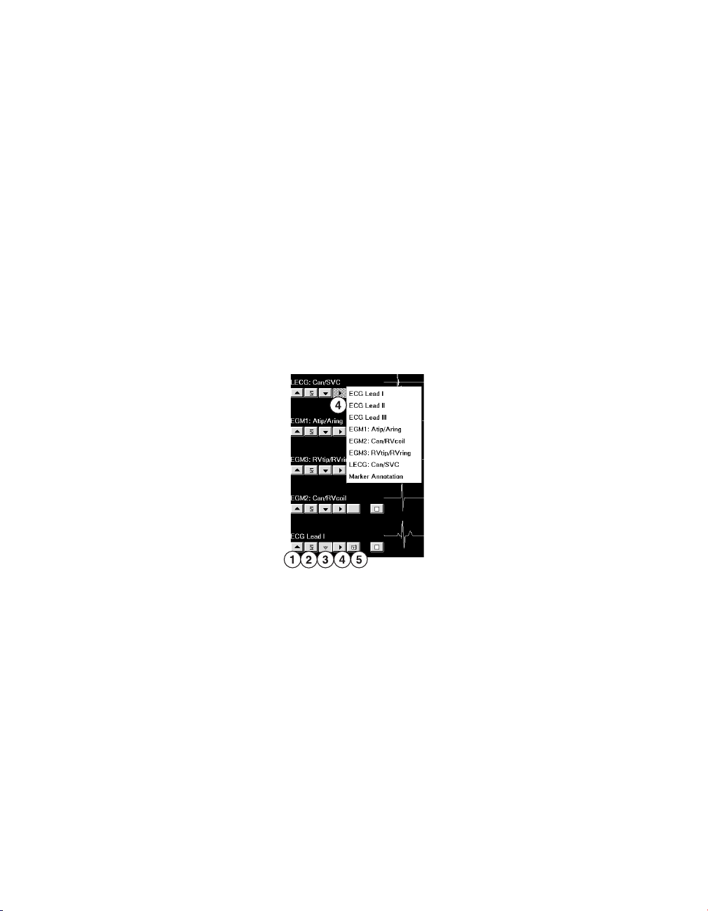
2.7.2.1 How to select and adjust the waveforms
You can use the waveform adjustment button bar to change the appearance of the
waveforms in view.
1. Select the up arrow button to increase the size of the waveform trace.
2. Select the normalize button to restore the waveform trace to its default size.
3. Select the down arrow button to decrease the size of the waveform trace.
4. Select the forward arrow button to choose which waveform trace to display.
5. Select the waveform print selection button to select the waveform trace for printing, if
available. You can select up to 2 waveform traces for printing.
30 Reference Manual
Page 31

Medtronic
EVERA™ DR
2.7.2.2 How to change the appearance of the waveform
You can use the Adjust window to make additional changes to the waveform display.
1. Select [Adjust…] to display the full screen Live Rhythm Monitor and the Adjust window.
2. Adjust the size, source, and print selection options for each waveform trace using the
waveform adjustment button bar.
3. Select the color button to change the color of a waveform.
4. Select or clear the Clipping, ECG Filter, and Show Artifacts check boxes as desired.
●
Clipping truncates the tops and bottoms of waveform traces at a 22 mm boundary.
●
ECG Filter changes the bandwidth of waveforms to improve the clarity of the
displayed ECG in the presence of interference. (Select the check box to set the
bandwidth to 0.5 to 40 Hz, or clear the check box to set the bandwidth to 0.05 to
100 Hz.)
●
Show Artifacts displays pacing artifacts superimposed over waveform traces.
5. Select a Sweep Speed if desired. Sweep Speed controls how quickly the waveform is
drawn across the display. Selecting a fast Sweep Speed produces a wide waveform.
Selecting a slow Sweep Speed produces a narrow waveform. Sweep Speed can be set
to 12.5, 25, 50, or 100 mm/s.
6. Select [Normalize] to equalize the spacing between the waveform traces and to resize
each trace to its default setting.
Reference Manual 31
Page 32

Medtronic
7. Select the calibrate button to add a reference signal to the analog output, the screen,
and the real-time strip recorder or Electronic Strip Chart (eStrip) recorder, whichever is
available.
8. When you finish making adjustments, select [OK].
EVERA™ DR
2.7.2.3 How to interpret Marker Channel annotations and symbols
Marker Channel annotations appear as 2 characters above or below the Marker Channel
waveform trace. Annotations indicate events such as pacing, sensing, detection, and
delivered therapies.
Real-time waveform recordings also display symbols that appear above or below their
associated Marker Channel annotations. The symbols sometimes appear compressed
when printed, depending on the printout speed of the programmer strip chart recorder, if
available.
See the figures that follow for examples of Marker Channel annotations and symbols.
Note: Any interruption in telemetry with the device may result in missing marker annotations
and symbols on the waveform trace display.
32 Reference Manual
Page 33

A
S
A
R
A
b
A
P
V
S
V
S
V
P
E
R
V
R
M
S
P
P
Atrial pace
Atrial sense
Atrial refractory
sense
Atrial sense in
PVAB
Ventricular pace
Ventricular
sense
Ventricular
refractory sense
Ventricular
safety pace
Mode switch
Marker buffer full
Proactive pace
Medtronic EVERA™ DR
Figure 10. Pacing Marker Channel annotations and symbols
Reference Manual 33
Page 34

F
S
T
S
T
P
A
P
C
D
F
D
T
D
C
E
AT/AF sense
Atrial tachy
pace
Fast AT/AF
sense
AT/AF
detection
Fast AT/AF
detection
Cardioversion
pulse
Charge end
Atrial 50 Hz
burst
T
S
T
F
T
D
V
T
F
D
T
P
T •
F
T
F •
F
S
C
E
C
D
V
P
VT sense FVT sense via VTFVT sense via
VF
VF sense
VT detection FVT detection VF detection VT monitor
detection
Ventricular
tachy pace
50 Hz Burst
induction
Charge end
Cardioversion/
defibrillation
pulse
Medtronic
EVERA™ DR
Figure 11. Atrial detection and therapies Marker Channel annotations and symbols
Figure 12. Ventricular detection and therapies Marker Channel annotations and symbols
34 Reference Manual
Page 35

Medtronic EVERA™ DR
2.7.3 Recording live waveform traces
At any time during a patient session, you can record a continuous, live waveform trace of the
patient’s ECG, LECG, and EGM in either of two ways:
1. on an internal strip chart recorder, if available on your Medtronic programmer.
Note: Because the printed waveform strip is of a higher resolution than the programmer
display, the printed waveform strip may show artifacts and events that do not appear on
the programmer display.
2. on an Electronic Strip Chart (eStrip) recorder, if available on your Medtronic
programmer.
A printout or recording of the live waveform trace includes the following information:
●
ECG, LECG, and EGM traces
●
an indication of an executed command when confirmation of the command is received
●
test values during system tests
●
telemetry markers that show telemetry from the programmer to the device
(programming the device) and telemetry from the device to the programmer (confirming
the programming)
●
Decision Channel annotations. For more information, see Section 3.8, “Arrhythmia
Episodes data”, page 117.
Printing a report while recording a live waveform trace – If you select an option from the
Print menu while recording a live waveform trace, the report goes to the print queue.
Alternatively, if you start recording a live waveform trace while the programmer is printing a
report, the report stops printing and returns to the print queue.
2
Note: This interruption to printing applies only to reports printed on the programmer strip
chart recorder, if available with your Medtronic programmer. Printing to an external printer is
not affected.
EGM or LECG Range – The programmer cannot display or record an EGM or LECG
waveform trace until the current EGM Range or LECG Range setting has been interrogated
from the device. If you program an EGM Range or LECG Range setting during a recording,
the programmer marks the change with a vertical dotted line on the paper recording.
2
Programmers that feature a strip chart recorder cannot display or record an EGM or LECG trace until the device
has been interrogated.
Reference Manual 35
Page 36

Medtronic
EVERA™ DR
2.7.4 Freezing live waveform traces
The Freeze feature enables you to freeze the last 15 s of all live waveform traces displayed
in the expanded Live Rhythm Monitor window.
You can use controls in the frozen strip viewing window to perform the following functions:
●
View earlier or later portions of the strip by using the horizontal scroll bar.
●
See frozen waveform strips that are not visible in the window by using the vertical scroll
bar.
●
Measure a time interval with on-screen calipers.
Figure 13. Interpreting the frozen strip viewing window
1 The [Freeze] button freezes a live waveform trace and displays it in the frozen strip viewing
window on the programmer screen.
2 The [Adjust…] button opens the Adjust window for the strip viewer.
3 The Adjust window offers display options for the strip viewer, which is similar to the Adjust window
for the Live Rhythm Monitor.
4 The waveform adjustment button bar allows you to normalize the trace, resize the trace, and
change the waveform source.
5 The on-screen calipers define time intervals.
6 The arrow buttons move the on-screen calipers to show the beginning and the end of a time
interval.
7 The Calipers measurement is the time interval between the on-screen calipers.
8 The [Strips…] button opens a list of other frozen strips.
36 Reference Manual
Page 37

Medtronic
9 The [Save] button saves the on-screen frozen strip.
10 The [Delete] button deletes the on-screen frozen strip (if it was saved).
11 The [Print…] button prints the on-screen frozen strip.
12 The [Close] button closes the frozen strip viewing window.
EVERA™ DR
2.7.5 Recalling waveform strips
Before ending the patient session, you can recall any waveform strip collected and saved
during the session in order to view, adjust, and print the waveform strip.
2.7.5.1 How to recall a waveform strip
1. Select [Strips…] in the tool palette or in the strip viewer.
2. Select a strip to view.
3. Select [Open]. The strip viewer displays the selected strip.
Reference Manual 37
Page 38

Medtronic
EVERA™ DR
2.8 Navigating a patient session with Checklist
Use the Checklist feature to cycle through common tasks that are performed during an
implant session or a follow-up session. When you select a task, the associated programmer
screen for that task appears. Once you complete a task, you can either go back to the
Checklist or continue on to the screen associated with the next task. You can use the
standard checklists created by Medtronic, or you can create customized checklists that
reflect your personal workflow.
2.8.1 How to use a standard checklist
1. Select the Checklist icon on the right side of the programmer screen. Two standard
checklists are available: the Medtronic Standard Followup checklist and the Medtronic
Standard Implant checklist.
2. Select the checklist you want from the Checklist field.
3. Select either the [>>] button next to the Checklist icon or the [Go To Task] button to start
using the checklist.
4. Use the [>>] button to continue from one task to the next. Any time you want to return to
the Task list, select the Checklist icon.
5. To repeat a task or perform a task out of order, select the task and use the [Go To Task]
button or the [>>] button.
Once you have completed all the tasks on the Task list, [>>] and [Go To Task] become
inactive. However, you can still select a task and use either button to complete the task. You
can also use [>>] to advance through the tasks on the list.
Check marks appear next to the names of any programmer screens that were visited during
a session.
38 Reference Manual
Page 39

Medtronic
EVERA™ DR
2.8.2 How to create and use a custom checklist
1. Select the Checklist icon.
2. Select [New…] from the Checklist screen.
3. Choose the tasks you want in your customized checklist from the box on the left.
4. The tasks you select appear in the box on the right. You can add the same task more
than once. If you want a new task to appear somewhere else in the list rather than at the
end, highlight the task that the new task should follow, and select the new task. The new
task appears below the highlighted task.
5. To delete a task, highlight the task in the Tasks in this checklist box and select [Delete
Task].
6. To name your checklist, select the Checklist name field, and enter a name.
7. Select [Save].
To edit a custom checklist, select the checklist in the Checklist field and select [Edit…]. Add
or delete tasks as needed. Then select [Save].
To rename a custom checklist, select the checklist in the Checklist field and select [Edit…].
Change the name and select [Save].
To delete a custom checklist, select the checklist from the Checklist field and select [Delete].
After a custom checklist has been deleted, it cannot be restored. The Medtronic Standard
Followup checklist and the Medtronic Standard Implant checklist cannot be edited or
deleted.
Reference Manual 39
Page 40

Medtronic
EVERA™ DR
2.9 Programming device parameters
The Parameters screen is used for viewing and programming parameters that control device
functions and data collection. All device parameters that you can view and program appear
as “active fields” in the task area. Active fields, which appear as unshaded boxes next to
parameter names, respond to the touch pen. Some active fields pertain to only 1 parameter,
while other fields provide access to groups of parameters. If a parameter cannot be
programmed, no active field appears next to its name. All permanent parameter changes
can be programmed at the Parameters screen.
After you select new values for parameters, the new values are designated as pending
values. A field containing a pending value has a dashed rectangle as its border. Values
remain pending until they are programmed to device memory.
2.9.1 Understanding the symbols used on the Parameters screen
The following symbols can appear next to a parameter value.
Table 4. Symbols that appear with parameter values
Symbol Definition
This symbol indicates that the value is the Medtronic nominal value.
This symbol indicates that the value is the programmed value.
This symbol indicates that the programmed value can be changed automatically by the device. The adaptive symbol does not necessarily indicate that the
parameter value has been adapted from a previously programmed value. It
only indicates that it is able to be adapted.
This symbol indicates that the parameter value conflicts with the setting of
another present or pending value. A parameter interlock exists.
This symbol indicates that a warning message is available about the value. A
parameter warning exists.
Certain combinations of parameter values are restricted because they are invalid or result in
undesirable interactions. The programmer recognizes these combinations and may not
allow programming until all parameter conflicts are resolved and all parameter selection
requirements are met. If a parameter interlock symbol appears, select another value or
resolve the conflicting parameter value before programming the parameter. If a parameter
warning exists, select the message button to read the warning and view recommendations.
40 Reference Manual
Page 41

Medtronic
EVERA™ DR
The programmer may display a message button next to the [PROGRAM] button that
accesses additional information about the pending parameters. When the message button
is selected, the programmer opens a second window displaying one or more messages. The
message button has one of the symbols described in Table 5.
Table 5. Symbols that appear on the message button
Symbol Explanation
Interlock – Indicates that a parameter interlock exists. Programming is
restricted until you resolve the conflict. Select this button for a message that
describes the conflict.
Warning – Indicates that there is a warning associated with programming
one or more of the pending parameter values. Select this button to view the
warning message and recommendations.
Informational – Indicates that there is an informational message about one
or more of the parameter values. Select this button to view the message.
If there are multiple messages regarding the pending parameter values, the most significant
message determines the symbol that appears on the button.
2.9.2 How to access parameters
1. Select a parameter field. If there are only 2 values, such as Off and On, the parameter
field typically switches to the alternate value. If there are more than 2 values, a window
opens showing available values for that parameter. If the parameter or parameter field
contains an ellipsis (…), another screen appears, providing additional parameter
selections.
2. Select the desired new value or values. The new values display as pending values. (You
can also select [Close] to close the window without changing parameter values.)
3. If necessary, select [OK] to return to the Parameters screen.
4. Select [PROGRAM] to program the new value to the device memory.
Reference Manual 41
Page 42

Medtronic
2.9.3 How to access a group of related parameters
EVERA™ DR
1. Select a parameter or a parameter field that ends with an ellipsis or a parameter field
that contains a list of parameter names. A screen appears that displays related
secondary parameter fields. In the example shown, Data Collection Setup… was
chosen.
2. Select new values for the desired secondary parameters. New values are displayed as
pending values.
3. Select [OK] to close the secondary parameters screen and return to the Parameters
screen.
4. Select [PROGRAM] to program the new values to device memory.
42 Reference Manual
Page 43

Medtronic
EVERA™ DR
2.10 Saving and retrieving a set of parameter values
Custom sets of parameter values can be saved on the programmer hard drive and retrieved
either in the current patient session or in subsequent patient sessions. This flexibility allows
you to save and quickly access a custom set of parameter values for a particular clinical
situation. For example, you may want to save a set of parameter values for an initial implant
setting, for a specific disease state, or for situations in which you need to repeatedly program
a particular set of parameters.
The [Save…] button opens a window where you can assign a name to the set of parameter
values presently displayed by the Parameters screen. A saved parameters set can include
both programmed and pending values. The [Get…] button opens the Get Parameter Set
window to retrieve a Medtronic Nominals parameter set, an Initial Interrogation parameter
set, or a custom parameter set.
2.10.1 How to save a set of parameter values
1. Select the Params icon.
2. Make the desired parameter selections.
3. Select [Save…] to open the Parameter Set Name window.
4. Type a name for the parameter set, and select either [OK] or [ENTER].
5. If a parameter set exists with that name, confirm that you want to replace the existing set
with a new set, or change the name of the new set of parameters.
2.10.2 How to retrieve a set of parameter values
1. Select the Params icon.
2. Select [Get…] to open the Get Parameter Set window.
3. Select the parameter set you want to retrieve.
4. Select [Set Pending].
5. Select [PROGRAM] to apply the pending values.
You can select the following options from the Get Parameter Set window:
●
Medtronic Nominals: Values chosen as nominal values for the device by Medtronic. The
Medtronic Nominals cannot be customized or deleted.
●
Initial Interrogation Values: The permanently programmed parameter values as
determined by the first interrogation of the device during the patient session.
●
Custom sets of values: All custom sets of values that were saved previously.
Reference Manual 43
Page 44

Medtronic
To remove a parameter set from the list, choose the parameter set and select [Delete].
EVERA™ DR
2.11 Using TherapyGuide to select parameter values
Caution: TherapyGuide does not replace a physician’s expert judgment. The physician’s
knowledge of the patient’s medical condition goes beyond the set of inputs presented to
TherapyGuide. The physician is free to accept, reject, or modify any of the suggested
parameter values.
TherapyGuide offers a simple clinically focused method to obtain suggested parameter
values. At implant or at an early follow-up appointment, information can be entered about the
patient’s clinical conditions. Based on those inputs, the programmer suggests parameter
values. The suggestions are based on clinical studies, literature, current practice, and
physician feedback.
2.11.1 Operation of TherapyGuide
The patient’s clinical conditions are entered in the TherapyGuide window, which is accessed
from the Parameters screen or by selecting Patient > TherapyGuide.
Figure 14. TherapyGuide window
44 Reference Manual
Page 45

Medtronic
EVERA™ DR
Based on a set of selected clinical conditions, TherapyGuide provides suggested values for
many programmable parameters. The clinical conditions influencing these parameter
suggestions are shown in Table 6. This table presents an overview, but the Rationale window
shows how the suggested values for parameters relate to specific settings for the clinical
conditions.
If clinical conditions do not influence a parameter, TherapyGuide may either recommend the
Medtronic nominal value for that parameter or make no recommendation.
If the suggested value for a parameter is different from the programmed value, the parameter
value appears as a pending value. If the suggested value is identical to the programmed
value, it does not appear as a pending value.
Table 6. How programming suggestions are determined
Programming suggestions Clinical conditions
VF Detection VT/VF
Slowest VT
VT Detection VT/VF
Slowest VT
VT Monitor Atrial Status
AV Conduction
Date of Birth
Treated Cutoff
Pacing Mode Atrial Status
AV Conduction
Lower Rate Atrial Status
Date of Birth
Upper Tracking Rate AV Conduction
Date of Birth
Treated Cutoff
Rate Drop Response Atrial Status
Rate Response
(including Upper Sensor Rate)
a
The Treated Cutoff equals the VT detection interval if VT Detection Enable is On. Otherwise, the Treated Cutoff
is the VF detection interval.
Atrial Status
Heart Failure
Date of Birth
Activity Level
a
a
2.11.2 Considerations for TherapyGuide
TherapyGuide and the Patient Information screen – The clinical conditions can also be
programmed into device memory from the Patient Information screen. For more information,
see Section 2.12, “Storing patient information”, page 47.
Reference Manual 45
Page 46

Medtronic
EVERA™ DR
Last Update status – The date indicates when changes in clinical conditions were last
programmed into device memory.
Printing the clinical conditions – The clinical conditions can be printed from the Patient
Information screen. The clinical conditions are also included in the Initial Interrogation
Report and in the Save To Media file.
Appearance of the [TherapyGuide…] button – The appearance of the [TherapyGuide…]
button changes about 10 days after implant.
2.11.3 How to obtain a set of suggested values
1. On the Parameters screen, select [TherapyGuide…] to open the TherapyGuide
window.
2. For each clinical condition, select the field next to the condition and choose one of the
listed inputs.
Note: If you want to program only the choices for clinical conditions without
programming any parameter changes into device memory, select [Close] and
[PROGRAM].
3. After selecting the clinical conditions, select [Get Suggestions]. The TherapyGuide
window closes, and suggested changes to parameter values appear as pending values
on the Parameters screen.
Notes:
●
Information is stored in device memory only after you select [PROGRAM] on the
Parameters screen.
●
If you select [Undo] on the Parameters screen, all pending parameter values and
the pending clinical conditions are cleared.
4. Review the settings and verify that the new settings are appropriate for the patient.
5. To adjust any of the pending values, select [Undo Pending] within the parameter value
window, or select a different parameter value. Repeat this step to adjust other
parameter values as desired.
6. Select [PROGRAM] to enter the pending parameter values and the pending clinical
conditions into device memory.
46 Reference Manual
Page 47

Medtronic
EVERA™ DR
2.11.4 How to view the rationale for TherapyGuide suggestions
1. On the Parameters screen, select [TherapyGuide…] to open the TherapyGuide
window.
2. Select [Rationale…] to open the Rationale window.
3. Select [Close] twice to return to the Parameters screen.
2.12 Storing patient information
Devices can store patient-related information that you can view and print during a patient
session. This information is typically programmed into the device at the time of implant, but
it can be revised at any time.
When you enter the patient’s clinical conditions (Date of Birth and History) and program them
into device memory, they are available to the TherapyGuide feature. Likewise, this same
information programmed through the TherapyGuide feature appears in the Patient
Information screen. For more information, see Section 2.11, “Using TherapyGuide to select
parameter values”, page 44.
The patient’s name and ID and the device serial number are printed on all full-size and strip
chart reports. If the programmer is using wireless telemetry, the patient is also identified at
the bottom of the programmer screen, either by the patient’s name or by the patient ID (if the
patient’s name was not entered).
Note: The Patient Information screen should not be used in the place of the patient’s medical
chart.
If you enter text that does not fit in the parameter display area, the entry is shortened. The full
entry is visible on the Patient Information Report. When displayed or printed from other
screens, the text entry may be shortened.
If you start a concurrent analyzer session during the device session, you can export analyzer
lead measurements. The exported measurements appear as pending parameter values in
the Implant window, which is accessed from the Patient Information screen. These pending
values are programmed from the Patient Information screen.
2.12.1 How to view and enter patient information
Select Patient > Patient Information. The Patient Information screen appears. Select each
text field to enter or change its content.
Reference Manual 47
Page 48

Medtronic
1. Enter the patient’s name (29 character maximum).
2. Enter the patient’s ID (15 character maximum).
3. Select the patient’s date of birth.
4. The serial number of the implanted device.
5. Enter the information for up to 3 leads. Select the model, position, and manufacturer
from the lists of options. Enter the serial number and implant date.
EVERA™ DR
Note: If an implant procedure is in progress, consider making the measurements in a
concurrent analyzer session. Measurements can be exported directly to the Implant
window. See Section 2.12.2, “How to export saved lead measurements to the Implant
window”, page 49 for instructions. Otherwise, select a value for each parameter.
6. Export lead data from the analyzer, or enter lead data using the submenus. Enter the
results of defibrillation testing.
7. Enter notes about the patient.
8. Select the patient’s clinical conditions. This information is made available to
TherapyGuide.
9. Select the ejection fraction from a table of values in the first field, and enter the date in
the second field.
10. Select the physician’s name, phone number, and hospital from the lists. If information is
not on the list, add the information to the list and then select.
11. When you have entered the information in all fields, select [PROGRAM].
The date of the last Patient Information update appears automatically.
48 Reference Manual
Page 49

Medtronic
EVERA™ DR
2.12.2 How to export saved lead measurements to the Implant window
When analyzer and device sessions are running concurrently, you can export the saved lead
measurements from the analyzer session into the Implant window in the device session.
1. From the device session, launch a new analyzer session by selecting the Analyzer icon,
which is located on the task bar.
2. Make the desired lead measurements. Identify the measurements by lead type when
you save them.
3. Select [View Saved…].
4. Select which saved measurements to export. You can select up to one measurement for
each lead type.
5. Select [Export]. The selected settings are exported to the Implant window in the device
session.
6. When you are finished, select [Close].
7. Return to the device session by selecting the Device icon on the task bar.
The data is mapped to Atrial and RV columns in the Implant window. As described in
Section 2.12.1, “How to view and enter patient information”, page 47, you can add or change
an exported measurement by selecting a field in the Implant window. The exported values
are programmed from the Patient Information screen.
2.13 Printing reports
The programmer provides flexibility in printing reports that are available from the system. You
can print informative standard reports, and you can access print functions in a variety of
ways. You can also specify when to print a particular report and which printer to use.
2.13.1 Setting preferences for printing, reports, and tests
Preferences allows you to choose the printer you want to use, the number of copies to print,
and whether you want to print now or later. You can choose to print reports anytime during a
patient session. Your printing preferences are then applied automatically whenever you
select the [Print…] button.
If you prefer to set print preferences each time you print a report, select the check box next
to “Pop up these options when any Print button is selected”.
Reference Manual 49
Page 50

Medtronic
For more information about setting up an external full-size printer, see the user guide for your
Medtronic programmer.
EVERA™ DR
2.13.1.1 How to set preferences
1. After starting a patient session, select Reports > Preferences….
2. From the Index selection box, select the option you want: Printing, Initial Report, Final
Report, or Tests.
3. Select your preferences.
4. Select [OK].
Basic printing preferences take effect immediately and are applied at the end of the current
patient session. Initial Report preferences take effect at the start of a new session and remain
in effect until you change them and start a new session. The preferences you select for Final
Report persist between sessions and across most applications.
The Session Summary report always prints when you request a Final Report.
The Tests preference allows you to choose how waveform traces are displayed during a
selected follow-up test. You can choose to make the live rhythm display arrange the
waveforms to show the EGM of the heart chamber being tested or keep the waveform
arrangement unchanged. For more information on tests, see Chapter 7, “System test and EP
Study features”, page 337.
2.13.1.2 How to print an Initial Interrogation Report
The Initial Interrogation Report includes the Quick Look II report and the other reports you
selected from the preferences on the Initial Report window. If you select the check box next
to “Print Initial Interrogation Report after first interrogation” as a preference for the Initial
Report, the programmer automatically prints the reports after the first interrogation in a
patient session.
To print an Initial Interrogation Report for a patient session that is in progress, select the
check box next to “Print Initial Interrogation Report after first interrogation”. Then end the
current patient session and restart the patient session. If you have selected this option, the
Initial Interrogation Report prints automatically after interrogation.
2.13.2 Printing reports during and after a patient session
The programmer allows you to specify a particular set of reports for printing and to print a
report based on the screen you are viewing.
The system also allows you to print a summary report at the end of a patient session.
50 Reference Manual
Page 51

Medtronic
EVERA™ DR
2.13.2.1 How to print a customized set of reports
1. To print a customized set of reports, select Reports > Available Reports….
2. Select the reports you want to print. A report can be printed only if its data has been
collected. If no data has been collected, the name of the report appears unavailable.
3. Select [Print Options…]. Enter number of copies and select printer preference.
4. Select [Print Now] for immediate printing, or select [Print Later] to add the print request
to the print queue.
2.13.2.2 How to print a summary report for the patient session
1. Select Reports > Final Report….
2. If the printing preferences window appears, select printing preferences as desired. If
the printing preferences window does not appear, the Session Summary Report and
other reports you have selected print according to the previously set printing
preferences.
2.13.3 Managing the Print Queue
The Print Queue window indicates the printing status of reports that you select to print as you
progress through a patient session. To display the Print Queue window during a patient
session, select Reports > Print Queue. From this window you can check the status of print
jobs from the current patient session. You can print or delete a print job from the queue. A
report cannot be deleted if its status is “printing” or “waiting”.
When you end the patient session, the Print Queue window is still available. It lists any
reports held from that session and other sessions.
To display the Print Queue window when you are not in a patient session, select the Print
Queue icon from the Select Model screen. The Print Queue window lists any reports held
from that session and other sessions.
2.14 Transferring data to Paceart with SessionSync
The SessionSync feature enables you to transfer device data through your clinic network
between the Medtronic programmer and the Medtronic Paceart data management system,
if Paceart is available in your locale. Transferred device data can be stored and used for later
analysis and patient management.
Reference Manual 51
Page 52

Medtronic
EVERA™ DR
The SessionSync status icon indicates network connectivity and shows data transfer when
the SessionSync feature is enabled. The SessionSync Status screen provides information
about the connection status of the programmer to the data management system. Details
about the SessionSync status icon and connection status are provided in Section 2.14.4.2,
“States of the SessionSync status icon”, page 57.
Notes:
●
For information about searching, viewing, and printing data from the patient records
stored on the Medtronic Paceart data management system, consult the Paceart
documentation.
●
For information about saving data to media and retrieving, viewing, and printing data
from media, see Section 2.15, “Saving and retrieving device data”, page 58.
●
The SessionSync feature operates within the context of a patient session. For
information about patient sessions, see Section 2.2, “Starting a patient session”,
page 16 and Section 2.16, “Ending a patient session”, page 61.
2.14.1 Enabling and disabling the SessionSync feature
Typically, the SessionSync feature is enabled only once when it is first installed. Once the
SessionSync feature is enabled, any device application on the programmer that can use the
SessionSync feature has SessionSync functionality.
The SessionSync status icon indicates network connectivity and shows data transfer when
SessionSync is enabled. The SessionSync status icon is unavailable when the feature is
disabled, for example, during a patient session.
2.14.1.1 How to enable and disable the SessionSync feature
1. From the Desktop, select Programmer > Preferences.
2. Select SessionSync from the index menu.
3. Select Enabled to enable the SessionSync feature, or select Disabled to disable the
SessionSync feature.
52 Reference Manual
Page 53

Medtronic
EVERA™ DR
2.14.2 Configuring the SessionSync network connection
You must configure the programmer network settings to allow for data transfer.
2.14.2.1 Preparing to configure the SessionSync network connection
Physical connection – See the Medtronic programmer reference guide for instructions
describing how to connect an Ethernet cable from the programmer to your clinic’s network.
Gateway address – Before configuring the network connection, you need to know your
SessionSync Gateway address. If you do not have your SessionSync Gateway address,
contact your clinic’s technical support or Medtronic Paceart technical support at
1-800-PACEART.
2.14.2.2 How to configure the SessionSync network connection
1. From the Desktop, select Programmer > SessionSync Network Configuration….
2. Enter the Clinic Name.
3. Enter the IP address or hostname of the SessionSync Gateway.
4. Select [OK].
2.14.3 Transferring device data
Device data is transferred to the Medtronic Paceart data management system using either
Automatic SessionSync or Manual SessionSync.
2.14.3.1 Transferring session data with Automatic SessionSync
Perform the following steps to end the current session and use Automatic SessionSync to
transfer session data between the Medtronic programmer and the Medtronic Paceart data
management system.
1. Select [End Session…].
The End Session window is displayed.
Reference Manual 53
Page 54

Medtronic
Figure 15. End Session window
1 Automatic SessionSync check box
2. Make sure that the Automatic SessionSync check box is selected.
Notes:
●
The Automatic SessionSync check box is not visible in the End Session window if
device interrogation is not successful.
●
The Automatic SessionSync check box is not visible in the End Session window if
SessionSync is not enabled on the programmer.
EVERA™ DR
3. Select [End Now].
The following actions occur:
a. Data transfer begins immediately.
b. The SessionSync – Saving Session Data on Programmer window is displayed to
show the progress of the data transfer.
c. The programmer side of the SessionSync status icon turns blue after the data has
been saved on the programmer’s hard disk.
d. If the subsequent transfer is successful, the data management system side of the
SessionSync status icon turns blue.
See Section 2.14.4, “Viewing the SessionSync data transfer status”, page 56, for more
details about status icon indications.
54 Reference Manual
Page 55

Medtronic EVERA™ DR
Note: If error messages appear during the data transfer process, see Section 2.14.5,
“SessionSync error messages”, page 58, SessionSync error messages for a list of
message descriptions.
2.14.3.2 Transferring session data with Manual SessionSync
You can use Manual SessionSync at any time during a patient session to transfer session
data between the Medtronic programmer and the Medtronic Paceart data management
system.
To use Manual SessionSync, select Session > SessionSync…. The following events occur
during the data transfer process:
1. The SessionSync – Saving Session Data on Programmer window opens to show the
progress of session data being saved automatically on the programmer’s hard disk.
2. The programmer side of the SessionSync status icon turns blue after the data has been
saved on the programmer’s hard disk.
3. If the subsequent transfer is successful, the data management system side of the
SessionSync status icon turns blue.
See Section 2.14.4.2, “States of the SessionSync status icon”, page 57 for more
details.
Notes:
●
SessionSync may have been disabled outside the patient session. If so, SessionSync…
is not listed in the Session menu and the SessionSync status icon is unavailable.
●
The procedure in Section 2.14.3.1, “Transferring session data with Automatic
SessionSync”, page 53 allows you to transfer session data automatically, but it requires
that you end the current session to do so.
●
If error messages appear during the data transfer process, see Section 2.14.5,
“SessionSync error messages”, page 58 for a list of message descriptions.
2.14.3.3 Transferred data
The following table lists the device data that is transferred with Automatic SessionSync or
Manual SessionSync to the Medtronic Paceart data management system.
Table 7. Data transferred with SessionSync
Feature name Information exported
Therapy Parameters Initial interrogated values
Last programmed values
Patient Information Last programmed values
Reference Manual 55
Page 56

Medtronic
EVERA™ DR
Table 7. Data transferred with SessionSync (continued)
Feature name Information exported
Battery and Lead Measurements Last measured values
Threshold Tests
Sensing Tests
Automatic Diagnostics Event Counters
Device Memory Retrieved from interrogation performed only for saving session
a
Manual test results are saved only if the user has saved the results.
a
a
Last results for each test type conducted (for each chamber
tested)
Last results for each test type conducted (for each chamber
tested)
Atrial Arrhythmia Episodes
Ventricular Arrhythmia Episodes
Mode Switch Episodes
Rate Drop Response Episodes
data
2.14.4 Viewing the SessionSync data transfer status
The programmer indicates the status of the SessionSync feature through the SessionSync
status icon in the task bar and through the SessionSync Status screen.
When all components of the SessionSync status icon are unavailable on the task bar, it
means that the SessionSync feature has been disabled under the programmer preferences.
No data transfer can occur in this state.
The SessionSync status does not update dynamically when the SessionSync Status
window is open. To update the status, select the [Update Status] button.
2.14.4.1 How to view the status of the SessionSync feature from the programmer task bar
The programmer task bar displays a SessionSync status icon that indicates the current data
transfer activity and the status of the communication link between the programmer and data
management system. If the SessionSync feature is not installed on the programmer, the icon
will not be visible in the task bar.
Figure 16. SessionSync status icon on the programmer task bar
56 Reference Manual
Page 57

Medtronic
Figure 17. SessionSync status icon indicators
EVERA™ DR
1 Data management system status
2 Connection status
3 Programmer status
2.14.4.2 States of the SessionSync status icon
The following table lists the states of the SessionSync status icon that appears in the
programmer task bar.
Table 8. SessionSync status icon states
Part of SessionSync status icon Color What the color indicates
Data management system
status
Connection status Not visible No valid connection between the programmer
Programmer status Gray No session data files in the Transfer Queue
Gray No session data has been transferred to the
data management system
Blue All session data has been successfully trans-
ferred to the data management system
and the data management system
Green Valid connection between the programmer
and the data management system
Red circle with a line
through it
Blue Session data files in the Transfer Queue
A device application in use that does not support SessionSync
2.14.4.3 How to view the status of the SessionSync feature from the SessionSync Status screen
The SessionSync Status screen displays information about the data files being transferred
to the data management system using the SessionSync feature. Each status message
includes the date, time, and event information for the associated SessionSync event.
1. From the Desktop, select Programmer > SessionSync Status.
2. Select the [Update Status] button.
Note: Events displayed on the SessionSync Status screen are not automatically updated
when SessionSync Status is selected from the menu. The user must manually select the
[Update Status] button to refresh the events that are displayed.
Reference Manual 57
Page 58

Medtronic
EVERA™ DR
2.14.5 SessionSync error messages
Table 9. SessionSync error messages
Error Message What this means
Ending a Session without Automatic
SessionSync
Interrogation Required You must conduct an interrogation.
Data Transfer Failed The data cannot be transferred to the data manage-
Unable to Save Session Data The session data cannot be saved on the programm-
You have deselected the Automatic SessionSync
check box on the End Session window before selecting the [End Now] button.
ment system. The session data has been successfully
saved on the programmer’s hard disk but cannot be
transferred to the data management system.
Select [Retry] to retry the SessionSync operation.
- or Select [Cancel] to close the window.
er’s hard disk.
Select [Save to Disk…] to save the session data on a
floppy disk.
- or Select [End Now] to end the session without saving
the device data.
- or Select [Cancel] to close the window without saving the
device data.
2.15 Saving and retrieving device data
The programmer allows you to save interrogated device data from a patient session to a disk
or to a USB flash drive. Later, while no patient session is in progress, you can use the Read
From Media application on the programmer to retrieve, view, and print previously saved data.
Note: Medtronic programmers are equipped either of two ways: with a disk drive for 90 mm
(3.5 in) disks plus a USB port for USB flash drives, or with a USB port only. If your programmer
has a USB port only, please disregard content in this section that documents the use of disk
drives.
2.15.1 Saving device data
Any programmer equipped with a disk drive can read device data from or write device data
to a disk. However, if a USB flash drive is inserted into the programmer, it overrides the disk
drive for saving and retrieving device data. Disks may be used only when no USB flash drive
is inserted.
58 Reference Manual
Page 59

Medtronic
EVERA™ DR
Storage requirements – To ensure the integrity and security of patient information, use a
flash drive or a disk that is reserved for storage of programmer data.
Interrogate first – Interrogate the device before saving data to a USB flash drive or to a disk
because the programmer saves only the data it has interrogated. If the Interrogate How
Much? window is displayed, select Interrogate All to save a record of all the information from
the device. If an issue needs to be investigated, selecting the All option provides more data
for analysis.
Emergency functions while saving – During the save operation, the [Emergency] button
remains displayed, and all Emergency functions are available. If an error occurs during a
save, there may be a delay in initiating the Emergency screens. Therefore, it is suggested
that you not save to media during EP studies or when it is possible that Emergency functions
will be needed immediately. If an Emergency function is used during a save operation, the
device aborts the save operation.
2.15.1.1 Considerations for saving device data on a USB flash drive
Insert only one USB flash drive – Insert only one writable USB flash drive at a time.
Inserting additional USB flash drives results in an error during data-saving operations and
the USB indicator becomes unavailable.
Progress indicator – While a Save To Media action is in progress, the progress indicator
and the message “Save To Media - In Progress” are displayed. The progress indicator
displays the completion percentage. Before removing the USB flash drive, wait a few
seconds after the progress indicator shows 100%.
Programmer powered on – Insert a USB flash drive only if the programmer is powered on.
Insert a writable USB flash drive in the programmer using any available USB port. A slight
delay may occur while the USB flash drive is authorized. The USB indicator on the task bar
turns green to indicate that the USB flash drive is available for use and the disk icon becomes
unavailable.
Do not insert or remove a USB flash drive during the following operations:
●
programming a device
●
performing a save-to-disk
●
performing a reload session data operation
●
saving a report as a PDF file
2.15.1.2 How to save device data to a USB flash drive
1. Select [Interrogate…] to interrogate the device.
2. Insert a USB flash drive into the USB port on the programmer.
Reference Manual 59
Page 60

Medtronic
3. Select Session > Save To Media….
4. Select [Save].
You can also Save To Media when you select [End Session…].
EVERA™ DR
2.15.1.3 Preparing to save data to a disk
The disk must be a formatted, IBM-compatible, 90 mm (3.5 inch) disk.
If you save data to a disk that is corrupt or is not IBM-formatted, the programmer may become
unresponsive. If this situation occurs, remove the disk, turn off the programmer, and then turn
it on again. Normal operation should resume. Inform your Medtronic representative of this
occurrence.
2.15.1.4 How to save device data to a disk
1. Select [Interrogate…] to interrogate the device.
2. Select Session > Save To Media….
3. Insert a disk into the programmer disk drive.
4. Select [Save].
You also have the option to Save To Media when you select [End Session…].
2.15.2 Retrieving device data
When the programmer has read the data that was saved during a patient session, it presents
the information in a read-only view. In the read-only view, the data is presented in a slightly
different way than what is seen in a live session. No Live Rhythm Monitor window is displayed
because this is not a live session. Instead, the Live Rhythm Monitor window is replaced with
the device model and the words Read From Media. While in the Read From Media
application, the programmer allows you to view the saved data, print reports, and display all
programmed parameter values.
Reports that have been saved to media can only be viewed on a computer. They cannot be
viewed on the programmer itself. After saving, remove the storage media (USB flash drive or
disk) containing the reports and insert it into a computer equipped to display files that are in
PDF format.
All reports from one patient’s session are contained in one PDF file.
Warning: The Read From Media application is designed only for viewing saved data while
no patient session is in progress. You cannot program a device or deliver Emergency
therapies from the Read From Media application.
60 Reference Manual
Page 61

Medtronic
Device testing – You cannot perform tests on the device when reading data from media.
EVERA™ DR
2.15.2.1 How to read device data from a USB flash drive or a disk
1. Insert a USB flash drive or a disk that contains information saved during a patient
session.
2. From the Select Model screen, select the product category from the View list.
3. Select the Read From Media version of the device.
4. Select [Start].
5. Select [OK] after reading the warning message that informs you that programming a
device and emergency operations are not possible while you are in the Read From
Media application.
6. Select [Open File…].
7. Select the data record that displays the desired device serial number, date, and time.
8. Select [Open File]. The Read From Media screen displays information from the saved
session.
2.16 Ending a patient session
2.16.1 How to end a patient session
1. To review a list of programming changes made during this session, select
Session > Changes This Session.
2. To print a record of the changes, select [Print…].
3. Select [End Session…].
4. To save the session data to a USB flash drive or a disk, if available, select [Save To
Media…].
5. To end the session and return to the Select Model screen, select [End Session…] and
then [End Now].
2.17 Patient follow-up guidelines
Schedule regular patient follow-up sessions during the service life of the device. The first
follow-up session should occur within 72 hours of implant so that the patient can be checked
for lead dislodgment, wound healing, and postoperative complications.
Reference Manual 61
Page 62

Medtronic
EVERA™ DR
During the first few months after implant, the patient may require close monitoring. Schedule
follow-up sessions at least every 3 months to monitor the condition of the patient, the device,
and the leads and to verify that the device is configured appropriately for the patient.
2.17.1 Follow-up tools
The system provides several tools that are designed to increase the efficiency of follow-up
sessions.
Quick Look II screen – The Quick Look II screen appears when you start the programmer
application. It provides a summary of the most important indicators of the system operation
and the patient’s condition since the last follow-up session.
You can perform the following tasks from the Quick Look II screen:
●
Assess that the device is functioning correctly.
●
Review information about arrhythmia episodes and therapies.
●
Review any observations in the Observations window.
You can compare the information on the Quick Look II screen with historical information
about the patient contained in printed reports. For information about printing reports, see
Section 2.13, “Printing reports”, page 49. The printed reports should be retained in the
patient’s file for future reference.
Checklist – The Checklist feature provides a standard list of tasks to perform at a follow-up
session. You can also customize your own checklists. For more information, see Section 2.8,
“Navigating a patient session with Checklist”, page 38.
Leadless ECG (LECG) – Leadless ECG is designed to simplify and expedite patient
follow-up sessions by providing an alternative to obtaining an ECG signal without the need
to connect surface leads to the patient. You can view the Leadless ECG waveform trace on
the Live Rhythm Monitor window. Leadless ECG is available in the clinic, and at remote
locations. For more information, see Section 2.7, “Monitoring cardiac activity with the Live
Rhythm Monitor”, page 29.
Cardiac Compass Trends – Cardiac Compass Trends provides a picture of the patient’s
condition during the last 14 months. The report includes graphs that show trends in the
frequency of arrhythmias, the amount of physical activity, heart rates, and device therapies.
Dates and event annotations allow you to correlate trends from different graphs. The trends
can also help you to assess whether device therapies or drug therapies is effective. For more
information, see Section 3.6, “Cardiac Compass Trends”, page 104.
62 Reference Manual
Page 63

Medtronic
EVERA™ DR
2.17.2 Reviewing the presenting rhythm
The presenting rhythm may indicate the presence of undersensing, far-field oversensing, or
loss of capture. These are basic pacing issues that can affect the delivery of therapy. These
issues can often be resolved by making basic programming changes.
Review the presenting rhythm by viewing the Live Rhythm Monitor and by printing the EGM
and Marker Channel traces. If you identify issues with the patient’s presenting rhythm, review
the device settings and reprogram the device to values that are appropriate for the patient.
2.17.3 Verifying the status of the implanted system
To verify that the device and leads are functioning correctly, review the device and lead status
information, lead trends data, and Observations available from the Quick Look II screen.
For detailed information about viewing and interpreting all of the information available from
the Quick Look II screen, see Section 3.1, “Quick Look II summary data”, page 70.
2.17.3.1 How to review the Remaining Longevity estimate and device status indicators
Warning: Replace the device immediately if the programmer displays an EOS indicator. The
device may lose the ability to pace, sense, and deliver therapy adequately after the EOS
indicator appears.
Review the displayed Remaining Longevity estimate. If the programmer displays the RRT
indicator, contact your Medtronic representative and schedule an appointment to replace
the device. For more information, see Section 3.4, “Device and lead performance data”,
page 90.
2.17.3.2 How to assess the performance of the device and leads
1. To review trends in pacing impedance, capture thresholds, and P-wave and R-wave
amplitude, select the [>>] button next to the lead trend graphs on the Quick Look II
screen. The programmer displays a detailed history of automatic impedance, capture
threshold, and sensing measurements. For more information about viewing lead
performance trends data, see Section 3.4, “Device and lead performance data”,
page 90.
Reference Manual 63
Page 64

Medtronic
EVERA™ DR
2. If you also want to gather real-time information about the performance of the device and
leads during the follow-up session, you can perform the following tests:
●
Lead Impedance Test: Compare the results of the test to previous lead impedance
measurements to determine if there have been significant changes since the last
follow-up session. For more information, see Section 7.4, “Lead Impedance Test”,
page 343.
●
Sensing Test: Compare the test results to previous P-wave and R-wave amplitude
measurements. For more information, see Section 7.5, “Sensing Test”, page 344.
●
Pacing Threshold Test: Use the test to review the patient’s capture thresholds.
Determine the appropriate amplitude and pulse width settings to ensure capture
and maximize device longevity. For more information, see Section 7.2, “Pacing
Threshold Test”, page 338.
2.17.4 Verifying the clinical effectiveness of the implanted system
You can use the information available from the Quick Look II screen and in printed reports to
assess whether the device is providing adequate clinical support for the patient.
2.17.4.1 How to assess effective pacing therapy
1. Interview the patient to confirm that the patient is receiving adequate cardiac support for
daily living activities.
2. Review the pacing percentages on the Quick Look II screen, and view or print Rate
Histograms.
3. Review the Cardiac Compass Trends for comparison to patient history. Cardiac
Compass Trends can help you to determine whether changes in the patient’s activity,
pacing therapies, and arrhythmias have occurred during the past 14 months. For more
information, see Section 3.6, “Cardiac Compass Trends”, page 104.
Note: Rate Histograms can also be used to assess the patient’s pacing and sensing history.
2.17.4.2 How to assess accurate tachyarrhythmia detection
The system provides diagnostic episode records to help you accurately classify the patient’s
tachyarrhythmias. Review the tachyarrhythmia episode records since the last session and
the Quick Look II observations. For more information, see Section 3.8, “Arrhythmia Episodes
data”, page 117.
Episode misidentification – If the episode records indicate that the device has
misidentified the patient’s rhythm, carefully review the tachyarrhythmia episode and sensing
64 Reference Manual
Page 65

Medtronic
integrity data, the Cardiac Compass trend data, and the data stored for other episodes.
Consider adjusting the detection parameters and the SVT detection criteria as needed. For
more information about how to view sensing integrity data, see Section 4.1, “Sensing”,
page 142.
Caution: Use caution when reprogramming the detection or sensing parameters to ensure
that changes do not adversely affect VF detection. Ensure that appropriate sensing is
maintained. For more information, see Section 4.1, “Sensing”, page 142.
EVERA™ DR
2.17.4.3 How to assess appropriate tachyarrhythmia therapy
1. Review any Medtronic CareAlert Notifications in the Quick Look II Observations section
that relate to therapy delivery. To see detailed information about Medtronic CareAlert
Notifications, select Data > Alert Events.
2. Check tachyarrhythmia episode records to determine the effectiveness of therapies
that have been delivered.
3. Adjust the therapy parameters as needed.
2.18 Optimizing device longevity
Optimizing device longevity is a desirable goal because it may reduce the frequency of
device replacement for patients. Optimizing device longevity requires balancing the benefit
of device therapy and diagnostic features with the energy requirements placed on the battery
as a result of these features.
To view the Remaining Longevity estimate for the device, refer to the Quick Look II screen.
The following sections describe strategies that may help reduce the energy requirements
placed on the battery.
2.18.1 Promoting intrinsic AV conduction
Managed Ventricular Pacing (MVP) – The MVP feature promotes AV conduction by
reducing unnecessary right ventricular pacing. The primary benefit of the MVP feature is
therapeutic, but it may also preserve device longevity as a result of a decrease in the
percentage of pacing. For more information about the MVP feature, see Section 4.3,
“Managed Ventricular Pacing (MVP)”, page 162.
Promoting AV conduction with longer AV intervals – Another method of promoting AV
conduction is to increase the paced AV interval and the sensed AV interval. This action
allows intrinsic conduction to occur before a ventricular pace. Fewer pacing pulses may help
Reference Manual 65
Page 66

Medtronic
to preserve device longevity. For more information, see Section 4.2, “Basic pacing”,
page 152.
EVERA™ DR
2.18.2 Managing pacing outputs
Capture Management – Capture Management provides the device with automatic
monitoring and follow-up capabilities for managing pacing thresholds in the right ventricle
and right atrium. This feature is designed to monitor the pacing threshold and, optionally, to
adjust the pacing outputs to maintain capture. Programming Capture Management allows
the device to set the pacing amplitude just high enough to maintain capture while preserving
battery energy. For more information, see Section 4.5, “Capture Management”, page 176.
Manual optimization of amplitude and pulse width – If you choose to program the
Capture Management feature to Off, you can optimize the patient’s pacing output
parameters manually. Perform a Pacing Threshold Test to determine the patient’s pacing
thresholds. Select amplitude and pulse width settings that provide an adequate safety
margin above the patient’s pacing threshold. These actions decrease the pacing outputs
and preserve battery energy. For more information, see Section 7.2, “Pacing Threshold
Test”, page 338.
Pacing rate – The more paced events that are delivered, the more device longevity is
reduced. Make sure that you have not programmed an unnecessarily high pacing rate for the
patient. Carefully consider using features that increase the bradycardia pacing rate. Use
features such as Atrial Preference Pacing (APP), Conducted AF Response, and Rate
Response only for patients who can receive therapeutic benefit from the feature.
2.18.3 Optimizing tachyarrhythmia therapy settings
Defibrillation – To treat ventricular fibrillation episodes, the device may deliver defibrillation
therapy to terminate the episode and restore the patient’s normal sinus rhythm. The device
can be programmed to deliver a sequence of up to 6 defibrillation therapies. Although
defibrillation therapy expends a high level of energy, VF therapies should be programmed to
the maximum energy level. For more information about defibrillation energy, see
Section 6.5.2, “Programming VF therapies”, page 314.
Atrial cardioversion – You can program the device to deliver automatic atrial cardioversion
(CV) therapies to treat atrial tachyarrhythmia episodes. If you choose to treat the patient with
atrial CV therapies, you can extend device longevity by carefully considering how you
program the following parameters: the number of shocks delivered during a 24-hour cycle
and the Episode Duration before CV. It is recommended that CV therapy be set to full energy
to terminate the arrhythmia. For more information, see Section 6.3, “Atrial cardioversion”,
page 295.
66 Reference Manual
Page 67

Medtronic
Patient-activated cardioversion is another way to provide atrial cardioversion therapy. The
patient can use the InCheck Patient Assistant to signal the device to deliver atrial
cardioversion therapy as needed. Counsel the patient on the potential inappropriate overuse
of patient-activated cardioversion that can result in decreased device longevity. For more
information, see Section 6.4, “Patient-activated atrial cardioversion”, page 301.
Ventricular cardioversion – If you are providing ventricular cardioversion therapies for the
patient, consider programming the therapy energy to a value lower than the maximum
energy but high enough to terminate the VT. However, at least one VT therapy and one FVT
therapy in a sequence should be programmed to the maximum energy level. For more
information, see Section 6.7, “Ventricular cardioversion”, page 326.
FVT via VF detection – An FVT detection zone can be used to detect and treat a VT episode
that is in the rate zone for VF. This approach can help maintain reliable detection of VF while
allowing ATP to be delivered for fast VT episodes. For more information, see Section 5.2,
“VT/VF detection”, page 233.
Antitachycardia pacing (ATP) – ATP therapies interrupt the tachycardia episode and
restore the patient’s normal sinus rhythm. ATP therapies deliver pacing pulses instead of the
high-voltage shocks that are delivered in cardioversion therapy and defibrillation.
ATP therapy requires less battery energy than cardioversion or defibrillation. For some
patients, you may be able to program the device to deliver ATP therapies before delivering
high-voltage therapies.
For more information about ATP and atrial episodes, see Section 6.2, “Atrial ATP therapies”,
page 285. For more information about ATP and ventricular episodes, see Section 6.6,
“Ventricular ATP therapies”, page 316.
Delivering ATP before the first defibrillation – You can program the device to deliver ATP
therapy before delivering the first defibrillation therapy by enabling ATP During Charging or
ATP Before Charging. This action can prevent delivery of high-voltage therapy for rhythms
that can be terminated by ATP (rapid, monomorphic VT, for example).
If you program the ChargeSaver feature to On, the device can also automatically switch to
ATP Before Charging operation. This switch allows the device to attempt a sequence of ATP
therapy before charging the capacitors to treat a detected VF episode. For more information,
see Section 6.5, “VF therapies”, page 306.
EVERA™ DR
2.18.4 Considering how diagnostic features with data storage impact longevity
Pre-arrhythmia EGM storage – Continual use of Pre-arrhythmia EGM storage reduces
device longevity. For a patient with uniform tachyarrhythmia onset mechanisms, the greatest
benefit of Pre-arrhythmia EGM storage is obtained after capturing a few episodes.
Reference Manual 67
Page 68

Medtronic
EVERA™ DR
When Pre-arrhythmia EGM storage is on, the device collects up to 10 s of EGM data before
the onset of VT/VF, VT Monitor, or the detection of SVT episodes. The device stores up to 5 s
of EGM before AT/AF detection regardless of the Pre-arrhythmia EGM storage setting.
To balance the benefit of using the Pre-arrhythmia EGM storage feature with optimizing
device longevity, consider the following programming options:
●
Set Pre-arrhythmia EGM storage to On to capture possible changes in the
tachyarrhythmia onset mechanism following significant clinical adjustments such as
device implant, medication changes, and surgical procedures. Pre-arrhythmia EGM
storage may be set to On - 1 month, On - 3 months, or On Continuous. Select the setting
for the shortest time period that will provide the necessary data.
●
Set Pre-arrhythmia EGM storage to Off after you have obtained the data of interest.
Note: When Pre-arrhythmia EGM storage is set to Off, the device begins to store EGM
information for VT/VF, VT Monitor, and SVT episodes after the third tachyarrhythmia event
occurs. Though EGM is not recorded before the start of the arrhythmia, the device still
records up to 20 s of data before the onset or detection of the episode. This data includes
interval measurements and Marker Channel annotations. In addition, Flashback Memory
data is stored for the most recent tachyarrhythmia episodes.
Holter telemetry – Extended use of the Holter telemetry feature decreases device
longevity. The Holter telemetry feature continues to transmit EGM and Marker Channel data
for the programmed time duration regardless of whether the programming head is
positioned over the device.
Medtronic CareLink remote transmissions – When scheduling Medtronic CareLink
remote transmissions, be aware that increasing the frequency of remote transmissions
reduces implanted device service life by approximately 1 day for each additional
transmission. To conserve battery energy, schedule the lowest frequency of remote
transmissions that still allows for the desired monitoring of your patient’s device.
2.18.5 Managing wireless telemetry session duration
Reducing wireless telemetry session duration may help reduce the energy requirements
placed on the battery.
●
At implant and in the first 7 days after implant, the wireless telemetry session duration is
2 hours to provide time for implant, programming, and patient follow-up tasks. The
device transitions to Standby mode after 2 hours of programmer inactivity.
68 Reference Manual
Page 69

Medtronic EVERA™ DR
●
7 days after implant, the wireless telemetry session duration is reduced automatically to
5 min to help preserve device longevity. The device transitions to Standby mode after
5 min of programmer inactivity. If patient follow-up tasks require it and if the Extend
Wireless Telemetry Session feature is available, you can optionally extend the wireless
telemetry for a patient session to 2 hours by selecting Session > Extend Wireless
Telemetry Session and then selecting [Continue]. At the end of the session, the wireless
telemetry session duration for the patient reverts automatically to 5 min.
Reference Manual 69
Page 70

Medtronic
EVERA™ DR
3 Diagnostic data features
3.1 Quick Look II summary data
At the start of a patient session, it is useful to quickly view summary information about device
operation and the patient’s condition. This overview can help you to determine whether you
need to look more closely at diagnostic data or reprogram the device to optimize therapy for
the patient.
The Quick Look II screen provides a summary of the most important indicators of the system
operation and patient’s condition. It includes links to more detailed status and diagnostic
information stored in the device. Device and lead status information indicates whether the
system is operating as expected. Information about arrhythmia episodes and therapies
provided gives a picture of the patient’s clinical status since the last follow-up appointment.
System-defined observations alert you to unexpected conditions and suggest how to
optimize the device settings.
Note: The Quick Look II screen shows information collected since the last patient session
and stored in the device memory. Programming changes made during the current session
may also affect the Quick Look II Observations.
3.1.1 How to view the Quick Look II screen
The Quick Look II screen is automatically displayed after the patient session is started. You
can also access the Quick Look II screen by selecting Data > Quick Look II.
You can update the Quick Look II data during a session by reinterrogating the device.
70 Reference Manual
Page 71

Medtronic
3.1.2 Information provided by the Quick Look II screen
The Quick Look II screen shows information in 6 sections.
Figure 18. Quick Look II screen
EVERA™ DR
1 Remaining Longevity estimate
2 Lead status and trends
3 Pacing and sensing information
4 Arrhythmia episode information
5 Observations
6 Cardiac Compass Trends
If you select one of the displayed observations and more information about the selected
observation is available, the [>>] button becomes active. You can use the [>>] button to look
at relevant details.
3.1.2.1 Assessing the device and lead status
Remaining Longevity estimate – The device automatically calculates the estimated time
remaining until Recommended Replacement Time (RRT) based on automatic daily battery
voltage measurements, time since implant, programmed parameter settings, and device
recorded events. Remaining Longevity displays the estimated time remaining and a graphic
that shows the RRT period in red and the estimated remaining longevity in green.
Reference Manual 71
Page 72

Medtronic
EVERA™ DR
Figure 19. Remaining Longevity estimate
1 Estimated remaining longevity to RRT (years or months)
2 RRT (red bar)
3 Estimated remaining longevity to RRT (green bar)
4 Remaining Longevity marker
5 If estimated remaining longevity to RRT is greater than 5 years, the green bar is full
Select the Remaining Longevity [>>] button to see more detailed battery and lead
measurement data. The Battery and Lead Measurements screen and its associated printed
report provide the most recent Remaining Longevity estimates, battery voltage
measurement, and RRT indicator with date and time, if applicable. For more information,
including the date when the battery reaches RRT, see Section 3.4, “Device and lead
performance data”, page 90.
Lead status and trends – Information about lead status allows you to assess the
performance and integrity of leads and identify any unusual conditions. The “Last Measured”
column shows the most recently measured lead impedance for each lead.
Select the [>>] button in the “Last Measured” column to see more detailed lead
measurements and relevant programmed settings.
The lead trend graphs on the Quick Look II screen show lead impedance, capture threshold,
and sensing amplitude measurements recorded over the last 12 months.
Select the [>>] button beside any of the lead trend graphs to see more detailed information
about lead performance. The detailed trend graphs display up to 15 of the most recent daily
measurements and up to 80 weekly summary measurements (showing minimum,
maximum, and average values for each week).
For more information about lead performance graphs, see Section 3.4, “Device and lead
performance data”, page 90.
3.1.2.2 Assessing the patient’s condition
Pacing and sensing information – This information can help to assess the patient’s AV
conduction status and evaluate the effectiveness of programmed device settings.
72 Reference Manual
Page 73

Medtronic
EVERA™ DR
Information about atrial and ventricular pacing and sensing is shown as percentages of the
total time during the reporting period. This includes the percentage of time that AS-VS,
AS-VP, AP-VS, and AP-VP event sequences occurred.
“MVP On” and “MVP Off” refer to the currently programmed pacing mode, not the usage of
MVP mode pacing since the last session. If the device was programmed to an MVP mode
during the reporting period, a high percentage of ventricular pacing may indicate that the
patient has heart block.
The percentage of time that the patient experienced AT/AF can help you to assess the need
to adjust the patient’s device or drug-based therapies. The time in AT/AF is calculated from
the point of AT/AF onset. For more information, see Section 5.1, “AT/AF detection”,
page 227.
Note: The paced and sensed event counters do not count all events recorded by the device.
For example, a ventricular safety pace is considered to be a pace, and the preceding
ventricular sense is not counted. Due to rounding, percentages may not add up to 100%.
Arrhythmia episode information – This section shows the number of treated and
monitored arrhythmia episodes that have occurred since the last patient session. It also
shows the number of shocks that were delivered since the last session. In addition, it shows
the number of episodes for which ventricular oversensing (VOS) was detected by the TWave
Discrimination feature or the RV Lead Noise Discrimination feature.
Select the [>>] button to review details of all arrhythmia episodes. For more information, see
Section 3.8, “Arrhythmia Episodes data”, page 117.
3.1.2.3 Quick Look II Observations
Observations are based on an analysis of programmed parameters and data collected since
the last session. The following types of observations may occur:
●
Device status observations inform you when the device is approaching RRT or End of
Service (EOS). An observation is also reported if a charge circuit irregularity or device
reset has occurred.
●
Lead status observations report any potential issues with the sensing integrity of the
leads, possible lead dislodgments, and abnormal capture management results. You
may also be warned about possible inconsistencies in the programming of lead polarity.
●
Parameter observations warn of any inconsistencies in the programming of detection
and therapy parameters. One example is if certain parameter settings result in a therapy
being disabled.
Reference Manual 73
Page 74

Medtronic
●
Diagnostic data observations report noteworthy arrhythmia episodes. Examples include
EVERA™ DR
arrhythmias of different types occurring together and episodes for which therapies were
unsuccessful. Conditions that prevent diagnostic data from being collected effectively
are also reported.
●
Medtronic CareAlert observations can report system or device performance conditions
and certain heart rhythm conditions. For more information, see Section 3.2, “Medtronic
CareAlert events and notifications”, page 74.
●
Clinical status observations alert you to abnormal patient conditions, such as low activity
rates, unexpectedly high heart rates, high arrhythmia burden, or fluid accumulation.
If you select one of the displayed observations and more information about the selected
observation is available, the [>>] button becomes active. You can use the [>>] button to look
at relevant details.
3.2 Medtronic CareAlert events and notifications
Important clinical management and system performance events may occur between
scheduled patient sessions. These events may relate to clinical management data stored in
device memory or to inappropriate programmed settings or system issues that should be
investigated. The early detection and notification of these events, should they occur, enable
you to intervene promptly with appropriate care for your patient.
The device continuously monitors for a specified set of clinical management and system
performance events that may occur between scheduled follow-up sessions. If the device
detects that such an event has occurred and if alerting parameters are turned on, it responds
in the following ways:
●
Wireless signal and network transmission of event information
Medtronic CareAlert Monitoring continuously monitors for alert events. If an event
occurs, CareAlert Monitoring sends a wireless alert signal to your patient’s Medtronic
patient monitor. Upon receiving a signal, the monitor transmits the alert data to the
Medtronic CareLink Network, if programmed to do so.
●
Notification of alert event
Depending on the severity of the alert condition, you can set up Medtronic CareAlert
Notifications through the CareLink Network (if available) to hold the alert for routine
review at your office via email or the CareLink website or to notify you immediately via
voice message, text message, pager, email, website, or live call.
●
Patient alert
The device emits 1 of 2 tones to alert your patient, depending on the type and urgency
of the event that has occurred. The patient then responds according to your instructions.
74 Reference Manual
Page 75

Medtronic EVERA™ DR
3.2.1 Clinical management and system performance event alerts
3.2.1.1 Clinician-defined alerts (programmable)
Clinical Management Alerts
Possible Fluid Accumulation This alert indicates that the OptiVol 2.0 Fluid Index has met or excee-
ded the programmed OptiVol Threshold. Note that the OptiVol Alert
Enable parameter is permanently programmed to “Off (Observation
only)”, but the OptiVol Threshold parameter is programmable. If the
OptiVol 2.0 Fluid Index has exceeded the programmed threshold, the
fluid accumulation event is listed on the OptiVol Events screen and is
provided as an observation on the Quick Look II screen.
AT/AF Daily Burden >
Threshold
Avg. V. Rate During AT/AF >
Threshold
Number of Shocks Delivered
in an Episode
All Therapies in a Zone
Exhausted
Lead and Device Integrity Alerts
RV Lead Integrity This alert indicates that an RV lead problem is suspected, which
RV Lead Noise This alert indicates that noise was detected on the RV lead, which
VF Detection/Therapy Off This alert indicates that one or more of the following conditions has
Low Battery Voltage Recommended Replacement Time
This alert indicates that the cumulative time in AT/AF exceeds the
programmed threshold.
This alert indicates that the average ventricular rate during a selectable duration of AT/AF exceeds the programmed threshold.
This alert indicates that the number of shocks delivered in a VT/VF
episode is greater than or equal to the programmed Number of
Shocks Threshold.
This alert indicates that a specific VF, VT, or FVT episode was redetected after all programmed therapies for that type of episode were
delivered.
could indicate lead fracture. The device immediately sounds an alert
tone that lasts for 30 s. This tone repeats every 4 hours, beginning at
the next scheduled 4-hour time interval, and at the programmed daily
alert time.
could indicate lead fracture, breached lead insulation, lead dislodgement, or improper lead connection. The device sounds an alert tone
3 min after a lead noise episode is detected. This tone repeats every
4 hours, beginning at the next scheduled 4-hour time interval, and at
the programmed daily alert time.
occurred for at least 6 hours since the last programming: VF detection
has been turned off; 3 or more VF therapies have been turned off; or
FVT detection is programmed to FVT via VF and 3 or more FVT
therapies have been turned off. Note that this alert sounds immediately and then every 6 hours until cleared.
This alert indicates that the daily automatic battery voltage measurement has been at or below the Recommended Replacement Time
voltage level for 3 consecutive days.
Reference Manual 75
Page 76

Medtronic
EVERA™ DR
Excessive Charge Time End
of Service
(Lead Name) Impedance
Out of Range
This alert indicates that the charging period equals or exceeds the
charge time threshold.
This alert indicates that the daily lead impedance measurement for
the (lead name) is out of range. This could indicate that the lead has
dislodged or is improperly connected. For all leads, the device
sounds an alert tone at the programmed daily alert time. For the RV
Pacing, RV Defibrillation and SVC leads, the device also immediately
sounds an alert tone and repeats this tone every 4 hours, beginning
at the next scheduled 4-hour time interval.
For details about programmable settings for a particular parameter, see the device manual
for the specific device.
3.2.1.2 System-defined alerts (non-programmable)
Electrical Reset This alert indicates that the device has been reset and may require
reprogramming. The device immediately sounds a high-urgency alert
tone that repeats every 20 hours or every 9 hours, depending on the
type of electrical reset. Immediately contact your Medtronic representative if an Electrical Reset alert occurs. For electrical reset parameter values, see the device manual for the specific device.
Pacing Mode DOO, VOO, or
AOO
This alert indicates that the device is programmed to DOO, VOO, or
AOO pacing mode and, as such, does not deliver tachyarrhythmia
therapy. The device sounds a high-urgency tone daily at the programmed time.
Active Can Off without SVC This alert indicates that the Active Can feature is disabled without an
SVC lead in place, which does not provide a viable defibrillation pathway. The device sounds a high-urgency tone daily at the programmed
time.
Charge Circuit Timeout This alert indicates that a charging period has exceeded the maxi-
mum time allowed for capacitor charging. The device immediately
sounds a high-urgency alert tone that repeats every 20 hours. Contact
your Medtronic representative if a Charge Circuit Timeout alert
occurs.
Unsuccessful Wireless
Transmission
This alert indicates that the device attempted a wireless transmission,
but that the transmission was still unsuccessful after a 72-hour period
during which the device retried the transmission every 3 hours.
a
An Electrical Reset alert sounds immediately and then every 20 hours thereafter. However, if the electrical reset
disables tachyarrhythmia detection and therapy, the alert sounds immediately and then every 9 hours thereafter.
Contact your Medtronic representative if an electrical reset alert sounds.
a
76 Reference Manual
Page 77

Medtronic
EVERA™ DR
3.2.2 Operation of Medtronic CareAlert Monitoring and Medtronic CareAlert Notifications
If a clinical or system performance event occurs and the device is programmed to notify you
over the CareLink Network, CareAlert Monitoring automatically attempts to establish
wireless communication between the device and the monitor. Once communication is
established, the monitor receives the alert data from the device. The monitor then transmits
the alert data to the CareLink Network. The CareLink Network records the alert, and you are
notified based on your preferences. The monitor communicates back to the device when the
data transmission is successful. If a data transmission is unsuccessful at first, CareAlert
Monitoring attempts to establish wireless communication with the monitor every 3 hours until
the transmission is successful. If a transmission is still unsuccessful after 72 hours, the
device emits a backup tone at the Alert Time that you select for your patient or at intervals
unique to some alerts as described in Section 3.2.1.1, “Clinician-defined alerts
(programmable)”, page 75 and Section 3.2.1.2, “System-defined alerts (nonprogrammable)”, page 76. A transmission includes data for all active alerts.
Note: After a wireless alert signal has been successfully transmitted, the device does not
retransmit data for that particular alert until the alert is cleared, even if the threshold for the
alert is met again in the interim. However, the device continues to emit alert tones each day
for active alerts that have Device Tone set to On. There are no such tones emitted for alerts
that have Device Tone set to Off.
The CareAlert Notification methods (any one or a combination of voice message, text
message, pager, email, website, or live call) are set on a per-clinic basis according to alert
urgency and time of day. You can assign the level of urgency to each alert for individual
patients, so that the same alert can be high urgency for one patient and low urgency for
another patient.
Reference Manual 77
Page 78

Line
Phone
Guest
Medtronic
EVERA™ DR
Figure 20. Process for transmitting Medtronic CareAlert Notifications
1 The device detects an alert condition and establishes wireless communication with the monitor.
2 The monitor sends the alert data to a secure server via the patient’s telephone land line or cellular
telephone connection.
3 If the CareLink Network is configured to do so, the clinician is notified via voice message, text
message, pager, email, or website, or live call. The clinician can then consult the network for
detailed information.
3.2.3 Operation of Medtronic CareAlert events
Medtronic CareAlert events trigger patient alerts that are clinician-defined or system-defined
and emit tones that can be differentiated using 2 levels of urgency:
●
Clinician-defined alerts may be programmed as high-urgency or low-urgency and may
be turned on or off.
●
System-defined alerts are high-urgency, and they are always on.
High-urgency alerts emit a dual, high-low tone. Low-urgency alerts emit an intermittent
on-off tone. High-urgency tones may indicate that there is a device problem that needs
immediate attention. Alerts are displayed in the Observations window on the Quick Look II
and Alert Events screens of the Medtronic programmer.
When an alert is initiated, the device emits the tone pattern either at a selected time of day
or at a fixed time interval. The tone then sounds each day at the selected time or interval until
it is cleared through interrogation by the programmer. Active tones also sound when the
patient magnet is placed over the device. You can view alert details on a programmer during
a patient session.
78 Reference Manual
Page 79

Medtronic
EVERA™ DR
Notes:
●
A CareLink transmission does not clear an alert tone from sounding. The tone will
continue to sound until the alert is cleared (or until the Device Tone is set to Off).
●
Once an alert has been successfully transmitted over the CareLink Network (if
available), further transmissions for that alert condition will not occur until the alert is
cleared.
●
All alerts are cleared automatically when the device is interrogated with a programmer.
3.2.3.1 Patient alert process
If a clinical management or system performance event occurs and the device is programmed
to sound a patient alert, the device emits alert tones at any or all of the following times,
depending on the event: when the event occurs, at a programmed time of day, at fixed
intervals. Instruct your patient to call the clinic if the patient hears tones coming from the
device. Alert tones last for up to 30 s and are slightly louder than typical living room noise. If
both high-urgency and low-urgency alerts are active at the same time, the high-urgency alert
is given priority and sounds at the appropriate time or interval.
Although the system provides 2 types of alert tones for high-urgency and low-urgency
clinical scenarios, it is important to remember that the patient may hear identical tones
whether the alert is caused by a system performance issue or by a significant clinical event.
Because the tones may be identical, a patient may not be able to distinguish between a
system performance alert and a clinical event alert. The patient alert tone is only intended to
prompt the patient to contact you. You should be aware that a patient who hears an alert tone
will contact you to determine the type of alert that has occurred, the information the device
has recorded, and how you interpret the data to assist in a plan of care. The details related
to the alert, including the type of alert and detailed findings, are only available to the patient
through discussion with you.
3.2.3.2 Selecting a patient alert time
The system allows you to select the time of day that a patient alert sounds. The alert tone
continues to sound each day at the selected time until the alert is cleared (or until Device
Tone is set to Off). Select a time when the patient or a companion is most likely to hear the
tone. The following patient factors may influence your selection of the alert time:
●
when the patient will be in a predictably quiet setting
●
the patient’s daily schedule; for example, medication routines that may affect alertness
●
the patient’s hearing acuity
●
the presence or absence of companions who might also hear the tones
Reference Manual 79
Page 80

Medtronic
EVERA™ DR
Note: Some patient alerts will sound at times other than the programmed alert time. See
Section 3.2.1.1, “Clinician-defined alerts (programmable)”, page 75 and Section 3.2.1.2,
“System-defined alerts (non-programmable)”, page 76 for exceptions.
If the conditions that trigger an alert are intermittent, the alert event may not actually be
present when the alert tone sounds. Also, the alert time is based on the internal device clock.
It does not adjust for time zone changes.
3.2.3.3 Programming a patient alert time
Tones for some system alerts are synchronized to the time you program tones for
clinician-defined alerts. To program an alert time, select Params > Alert… > Alert Time….
However, if you program all clinician-defined alerts to Off, the Alert Time field is not shown.
In this situation, perform the following steps to program the Alert Time for these system alert
tones:
1. Program one of the programmable alerts to On to display the Alert Time field.
2. Select an alert time to apply to system alerts.
3. Reprogram the alert to Off.
3.2.3.4 Instructing the patient
It is important that patients understand that they may hear alert tones emitted from implanted
devices. They must know what to do when an alert sounds.
Warning: Make sure that patients understand that they must not carry, store, or leave the
patient magnet positioned over the device. Device operation is temporarily impaired when
the magnet is placed over the device and it must be moved away from the device to restore
normal operation.
●
Instruct patients to contact you immediately if they hear ANY tones from the device.
●
Advise patients of the time of day that you have programmed an alert tone to sound. If a
tone sounds, they should expect it to sound every day at that time until the alert is cleared
(or until the Device Tone is set to Off).
●
For patients with a Medtronic monitor, advise them that if an alert is not successfully
transmitted to the monitor within 72 hours, a high-urgency tone sounds each day at the
programmed alert time.
●
Make sure patients know that the alert time does not adjust for time zone changes.
80 Reference Manual
Page 81

Medtronic EVERA™ DR
●
Advise patients that they may hear a steady test tone or any active alert tones if they are
in the presence of a strong electromagnetic field, such as the field within a store theft
detector. Advise patients that the device operation is temporarily impaired in these
situations and that they should move away from the source of the interference to restore
normal device operation.
Patients should also understand the purpose of the patient magnet and how and when to use
it. Make sure that they know that current patient alerts sound when the patient magnet is
placed over the device. Demonstrate how to place the patient magnet over the device to
replay the alert tones, and review the patient magnet manual with them. Patients can use a
folded patient magnet manual as a reference card.
3.2.3.5 Demonstrating alert tones
During a patient session, you can demonstrate high-urgency tones, low-urgency tones, and
the test tone from the programmer as follows:
1. Select the Params icon.
2. Select Alert….
3. Select [Demonstrate Tones…].
4. Select [High-Urgency Condition Met], [Low-Urgency Condition Met], or [No Conditions
Met].
Note: Any active alert tones will sound when the patient magnet is placed over the device.
If there are no active alerts, the steady test tone will sound.
3.2.4 Programming Alerts
Note: The Medtronic CareAlert Setup screen shows either a Lead/Device Integrity Alerts
view or a Clinical Management Alerts view. To switch between views, select either [Clinical
Management Alerts…] or [Lead/Device Integrity Alerts…].
Note: Programming each Device Tone alert includes setting the alert urgency. Alerts for the
Patient Home Monitor do not have an urgency setting.
Table 10. How to navigate to parameters for Lead/Device Integrity Alerts
Parameters Path
Patient Home Monitor (Yes, No)
Alert Time…
Alert Urgency (High, Low)
RV Lead Integrity (On, Off)
RV Lead Noise (On, Off)
Reference Manual 81
Params > Alert… > Lead/Device Integrity
Alerts…
Params > Alert… > Lead/Device Integrity
Alerts… > RV Lead…
Page 82

Medtronic
EVERA™ DR
Table 10. How to navigate to parameters for Lead/Device Integrity Alerts (continued)
Parameters Path
Lead Impedance Out of Range
Alert Urgency (High, Low)
A. Pacing (On, Off [Observation only])
RV Pacing (On, Off [Observation only])
RV Defibrillation (On, Off [Observation only])
SVC Defibrillation (On, Off [Observation only])
Low Battery Voltage RRT
Alert Enable – Urgency (On-High, On-Low, Off)
Excessive Charge Time EOS
Alert Enable – Urgency (On-High, On-Low, Off)
VF Detection OFF, VF or FVT Therapies Off
(On-High, Off)
Params > Alert… > Lead/Device Integrity
Alerts… > Lead Impedance Out of Range… >
Lead Impedance > Enable
Params > Alert… > Lead/Device Integrity
Alerts… > Low Battery Voltage RRT…
Params > Alert… > Lead/Device Integrity
Alerts… > Excessive Charge Time EOS…
Params > Alert… > Lead/Device Integrity
Alerts… > VF Detection OFF, 3+ VF or 3+ FVT Rx
Off.
Table 11. How to navigate to parameters for Clinical Management Alerts
Parameters Path
Patient Home Monitor (Yes, No)
Alert Time…
OptiVol 2.0 Fluid Settings (Off [Observation
only])
OptiVol Threshold
Adjust Thoracic Reference Impedance Params > Alert… > OptiVol 2.0 Fluid Settings… >
AT/AF Daily Burden (On, Off [Observation only])
Burden
Avg. V. Rate During AT/AF (On, Off [Observation
only])
Burden
V. Rate
Number of Shocks Delivered in an Episode (On,
Off)
Alert Enable – Urgency (On-High, On-Low, Off)
Number of Shocks Threshold
All Therapies in a Zone Exhausted for an Episode
Alert Enable – Urgency (On-High, On-Low, Off)
Params > Alert…
Params > Alert… > OptiVol 2.0 Fluid Settings…
Additional Settings…
Params > Alert… > AT/AF Burden and Rate Settings…
Params > Alert… > Number of Shocks Delivered
in an Episode…
Params > Alert… > All Therapies in a Zone
Exhausted for an Episode.
Transmitting alerts – The ability to transmit Medtronic alerts to the CareLink Network is
programmable only when the Patient Home Monitor field on the programmer screen is
programmed to Yes.
82 Reference Manual
Page 83

Medtronic
Repetitive alerts – If a programmable alert is triggered so often that it loses its clinical value,
you may want to consider adjusting the alert threshold, programming the device to improve
therapy effectiveness, or turning off the alert.
EVERA™ DR
3.2.5 Evaluation of alert events
The device stores alert events in the Medtronic CareAlert Events log. The programmer
screen refers to alert events as Alert Events and OptiVol Events. For each alert event, a log
entry includes the date and time of the alert, a description of the event, and the measurement
or information that caused the event. Up to 15 Alert Events and the last 7 OptiVol Events are
stored. Alert data is cleared only when you clear all device data from the Data Collection
Setup screen.
Caution: Verify lead integrity when evaluating OptiVol Events. Loss of RVcoil integrity due to
lead fracture or insulation defect may adversely affect OptiVol Events.
To access alert events, select Data > Alert Events > Alert Events, or select Data > Alert
Events > OptiVol Events.
3.3 RV Lead Integrity Alert
RV lead fractures can cause oversensing, which can lead to inappropriate tachyarrhythmia
detection and shock. While some lead fractures occur suddenly and provide little warning,
other fractures are preceded by rapid, unexpected changes in lead impedance and short
episodes of oversensing. Monitoring for these changes may provide patients with enough
advance warning of a potential lead problem to avoid an inappropriate shock.
Medtronic leads – When used with Medtronic Fidelis leads, the RV Lead Integrity Alert
feature is designed to extend the advance warning time of a potential lead-related issue,
improve opportunities for more patients to recognize the audible alert, and reduce
inappropriate shocks. The RV Lead Integrity Alert feature is intended for patients who have
a Medtronic ICD or CRT-D device and a Sprint Fidelis lead (Models 6949, 6948, 6931, and
6930), based on performance data.
St. Jude Riata/Durata lead families – A retrospective analysis of data from the CareLink
system was performed to evaluate the performance of RV LIA compared to pace/sense
monitoring in St. Jude Riata/Durata lead families (n=6,123 as of October 2011).
Boston Scientific Endotak lead families – A retrospective analysis of data from the
CareLink system was performed to evaluate the performance of RV LIA compared to
pace/sense monitoring in Boston Scientific Endotak lead families (n=5,114 as of October
2011).
Reference Manual 83
Page 84

RV bipolar OR RVtip-to-coil
lead impedance
Response
Sensing Integrity Counter
High Rate-NS episodes
60 days
2 of 3 criteria
are met
CareAlert notification
Suspend detection during
nonwireless telemetry
Adjustments to
tachyarrhythmia detection
Medtronic EVERA™ DR
The RV LIA feature may not perform as well with a St. Jude Riata/Durata lead or a Boston
Scientific Endotak lead as it does with a Medtronic Sprint Fidelis lead. This is because
different lead designs may have different failure signatures and conditions that may or may
not be detected early by the RV LIA feature. The RV Lead Integrity Alert feature detects
issues with the pace/sense conductor only, and does not provide warning of issues related
to the high voltage conductor.
The RV Lead Integrity Alert feature is not intended to withhold therapy for true VT or VF. To
identify a potential lead issue, the RV Lead Integrity Alert monitors RV pacing lead
impedance measurements, the frequency of rapid non-sustained VT episodes, and the
frequency of short ventricular intervals counted on the Sensing Integrity Counter.
If the possibility of an impending RV lead fracture is indicated by the data, the RV Lead
Integrity Alert feature can trigger a Medtronic CareAlert Notification and an alert tone to warn
the patient. In addition, the RV Lead Integrity Alert feature automatically adjusts
tachyarrhythmia detection settings and diagnostic settings to avoid the delivery of an
inappropriate shock.
The RV Lead Integrity Alert feature is only one part of an overall monitoring and diagnostic
plan. Consequently, if the Medtronic ICD or CRT-D device is sounding an audible alert tone
or if the programmer indicates that an alert event has occurred, review the alert messages
and evaluate the diagnostic data to determine the likelihood of a lead integrity issue.
3.3.1 Operation of RV Lead Integrity Alert
Figure 21. Operation of RV Lead Integrity Alert
1 Lead Integrity Alert impedance is evaluated for both RV bipolar and RV tip-to-coil pacing
polarities. If either measurement goes out of range, the impedance criterion is met.
84 Reference Manual
Page 85

Medtronic
EVERA™ DR
The device continually monitors for a potential RV lead fracture using lead impedance
measurements for both RV pacing lead polarities, the Sensing Integrity Counter, and High
Rate-NS episode data. It identifies a potential lead fracture if at least 2 of the following criteria
have been met within the past 60 days:
●
An RV pacing lead impedance measurement for either polarity is less than 50% or
greater than 175% of the baseline impedance. The baseline measurement is the median
of the previous 13 daily measurements. A separate baseline is calculated for each RV
pacing vector. The RV bipolar and RV tip-to-coil impedance measurements are taken at
the same time each day.
●
The ventricular Sensing Integrity Counter is incremented by at least 30 within a period of
3 consecutive days or less.
Note: The Sensing Integrity Counter total displayed on the Battery and Lead
Measurements screen is the number of short ventricular intervals that occurred since the
last patient session. Therefore, the total could exceed 30 without satisfying the alert
criteria if the total was reached during a period of more than 3 consecutive days.
●
The device senses 2 High Rate-NS episodes with a 4-beat average R-R interval of less
than 220 ms.
If either the Device Tone or the Patient Home Monitor alert parameter for the RV Lead
Integrity Alert is programmed to On, the device responds to a potential RV lead fracture with
an alert tone, a Medtronic CareAlert Notification, and automatic adjustments to
tachyarrhythmia detection. When at least 1 High Rate-NS episode occurs or if the alert
criteria are met, the device automatically adjusts EGM storage operation.
If both the Device Tone and the Patient Home Monitor alert parameters for the RV Lead
Integrity Alert are programmed to Off, the device does not trigger a Medtronic CareAlert
Notification or an alert tone, and it does not adjust tachyarrhythmia detection parameters.
However, it records a Quick Look II observation for the lead warning, and it makes
adjustments to EGM storage.
3.3.1.1 RV Lead Integrity Alert tones and CareAlert Notifications
When the criteria for the RV Lead Integrity Alert are met, the device immediately sounds an
alert tone. The tone sounds again every 4 hours beginning at the next scheduled 4-hour time
interval (00:00, 04:00, 08:00…). The tone also sounds at the programmed Alert Time and
when a magnet is placed over the device. The tone continues to sound until the alert is
cleared (or until Device Tone is set to Off). If the Patient Home Monitor alert for the RV Lead
Integrity Alert is programmed to On, the device also attempts to send a wireless transmission
to the Medtronic patient monitor.
Reference Manual 85
Page 86

Medtronic
EVERA™ DR
3.3.1.2 Automatic adjustments to tachyarrhythmia detection
When the RV Lead Integrity Alert is triggered, the device automatically programs the VF
Initial Beats to Detect parameter to 30/40 (if it was less). If necessary, the device
automatically adjusts the Monitored VT Beats to Detect parameter and sets AT/AF Detection
to Monitor.
In addition, after the RV Lead Integrity Alert has been triggered, the device automatically
suspends tachyarrhythmia detection when it is interrogated using nonwireless telemetry by
a programmer or a Medtronic patient monitor. The device suspends detection to prevent
inappropriate therapy delivery during the telemetry session when a lead issue is suspected.
During a Medtronic patient monitor session, tachyarrhythmia detection resumes
automatically when the interrogation is complete. During a programmer session,
tachyarrhythmia detection can be resumed by selecting [Resume] at the top of the
programmer screen, by removing the programming head, or by ending the session and
removing the programming head.
Note: This suspension behavior occurs for all nonwireless sessions until 3 days have
passed since the alert was cleared or the device was interrogated.
3.3.1.3 EGM storage changes
When at least 1 High Rate-NS episode occurs, the device automatically adjusts EGM
storage operation in order to provide more diagnostic data to help identify a lead-related
issue. The device programs the Pre-arrhythmia EGM parameter to On - 1 month (unless the
previous setting provided more than 30 days of Pre-arrhythmia EGM storage remaining).
Notes:
●
The Pre-arrhythmia EGM parameter displays the programmed setting even when the
device adjusts EGM storage automatically after a High Rate-NS episode has occurred.
●
The changes to EGM storage occur even when the Device Tone and Patient Home
Monitor alert parameters for RV Lead Integrity Alert are programmed to Off.
If the Lead Impedance and Sensing Integrity Counter criteria are met, the device also
changes the criteria for storing High Rate-NS episodes, allowing a High Rate-NS episode
with EGM data to be recorded if a single ventricular interval less than 200 ms occurs. This
condition persists until a High Rate-NS episode occurs or until you interrogate the device.
86 Reference Manual
Page 87

Medtronic
EVERA™ DR
3.3.2 Programming RV Lead Integrity Alert
Note: The Medtronic CareAlert Setup screen shows either a Lead/Device Integrity Alerts
view or a Clinical Management Alerts view. To switch between views, select either [Clinical
Management Alerts…] or [Lead/Device Integrity Alerts…].
Note: Programming each Device Tone alert includes setting the alert urgency. Alerts for the
Patient Home Monitor do not have an urgency setting.
To navigate to the RV Lead Integrity Alert parameter, select Params > Alert… > Lead/Device
Integrity Alerts… > RV Lead….
VF Detection and VF therapies – If you program VF Detection or all of the VF therapies to
Off, the RV Lead Integrity Alert does not operate. The RV Lead Integrity Alert operation
resumes when you program VF Detection and the VF therapies to On, and only the data
collected after that time are applied to the alert criteria.
3.3.3 Evaluation of RV Lead Integrity Alert
If the device is sounding an alert tone or if the programmer indicates that an alert event has
occurred, review the alert messages and evaluate the diagnostic data to determine the
likelihood of a lead integrity issue.
3.3.3.1 CareAlert window
When the device is interrogated, a CareAlert window notifies you that an alert condition
exists, including the RV Lead Integrity Alert.
3.3.3.2 Quick Look II observations
Check the Quick Look II Observations list to verify that there is an RV Lead Integrity warning
by selecting Data > Quick Look II.
For detailed information about viewing and interpreting all of the information available from
the Quick Look II screen, see Section 3.1, “Quick Look II summary data”, page 70.
Reference Manual 87
Page 88

Medtronic
EVERA™ DR
3.3.3.3 Medtronic CareAlert Events
Check the CareAlert Events list to verify that there is an RV Lead Integrity warning by
selecting Data > Alert Events.
3.3.3.4 Sensing Integrity Counter
To access the Sensing Integrity Counter, select Data > Device/Lead Diagnostics > Battery
and Lead Measurements > [Open Data].
Sensing Integrity Counter – Check the Sensing Integrity Counter section of the Battery
and Lead Measurements screen for evidence of oversensing. For more information, see
Section 3.4, “Device and lead performance data”, page 90.
3.3.3.5 Arrhythmia Episodes (High Rate-NS)
If an RV Lead Integrity warning is present in Quick Look II Observations, select the
Observations [>>] button on the Quick Look II screen, or select Data > Clinical Diagnostics >
Arrhythmia Episodes > [Open Data].
Check the High Rate-NS episodes in the Arrhythmia Episodes window. A High Rate-NS
episode has an average ventricular rate greater than 273 bpm (less than 220 ms). If there are
2 or more High Rate-NS episodes, lead noise oversensing may have occurred. Review the
stored EGM to determine the cause of the oversensing.
88 Reference Manual
Page 89

Medtronic
Figure 22. High Rate-NS episode record
1 Average rate information
EVERA™ DR
3.3.3.6 Lead Trends
To access lead impedance trends, select Data > Device/Lead Diagnostics > Lead
Impedance Trends > [Open Data].
Check the Lead Impedance Trends for a sudden change in either the RV bipolar impedance
or the RV tip-to-coil impedance measurement. If at least 1 measurement is greater than
175% of the baseline value or is less than 50% of the baseline value, then the lead
impedance should be considered abnormal.
Reference Manual 89
Page 90

Medtronic
Figure 23. RV Lead Impedance Trend data
1 Baseline value
2 Abnormal impedance measurements
EVERA™ DR
3.4 Device and lead performance data
The device automatically measures and records device and lead performance data every
day. Detailed views of this data are available from the Battery and Lead Measurements
screen and the Lead Trends screen.
3.4.1 Viewing battery and lead measurement data
The Battery and Lead Measurements screen displays the most recent values for key
measures of device and lead performance. These may include automatically measured
values or those measured during manual system tests.
90 Reference Manual
Page 91

Medtronic
EVERA™ DR
3.4.1.1 How to view battery and lead measurement data
To access battery and lead measurement data, select Data > Device/Lead Diagnostics >
Battery and Lead Measurements > [Open Data].
Figure 24. Battery and Lead Measurements screen
1 Remaining Longevity information
2 Battery Voltage information
3 Capacitor charging information
4 Sensing Integrity Counter
5 Result of the last Atrial Lead Position Check
6 Most recent lead impedance measurements
7 Most recent daily automatic sensing amplitude measurements
8 Information about the last delivered high-voltage therapy
9 Select [Print…] to print a Battery and Lead Measurements Report
3.4.1.2 Remaining Longevity estimate
The device automatically calculates the estimated time remaining until RRT based on
automatic daily battery voltage measurements, time since implant, programmed parameter
settings, and device recorded events. The estimated Remaining Longevity, minimum
longevity, and maximum longevity are reported in years or months. The estimated
Remaining Longevity is also reported in a graphic for easy reference with the RRT period in
red and the estimated remaining longevity in green.
Reference Manual 91
Page 92

Medtronic EVERA™ DR
Figure 25. Remaining Longevity estimate
1 Estimated remaining longevity to RRT (years or months)
2 Minimum and Maximum remaining longevity to RRT (years or months)
3 RRT (red bar)
4 Estimated remaining longevity to RRT (green bar)
5 Remaining Longevity marker
6 If estimated remaining longevity to RRT is greater than 5 years, the green bar is full
Table 12. Remaining Longevity examples
Remaining Longevity Infor-
Device Scenario Device Status
Before implant - VF detection
Off
Before implant - the device may
have been exposed to cold temperatures
Immediately after implant - VF
detection On
Recommended Replacement
Time (RRT)
End of Service (EOS) Replace Device EOS EOS and the RRT date are dis-
Device Electrical Reset Re-Initializing The bar on the graphic is gray
Pre-Implant The bar on the graphic is green
Pre-Implant The bar on the graphic is gray
Initializing Remaining longevity estimator
Replace Device RRT RRT and the RRT date are dis-
mation
and the estimated remaining
longevity to RRT is > 5 years.
and estimated remaining longevity to RRT is not reported.
is initializing. Longevity estimate will be available within 24
hours.
played.
played.
and estimated remaining longevity values will be available
within 1 week.
92 Reference Manual
Page 93

Medtronic EVERA™ DR
3.4.1.3 Battery voltage and replacement indicators
The device measures the battery voltage automatically when telemetry is initiated at the start
of a session, when a lead impedance test is performed, and every day at 02:15 as part of the
automatic daily measurements. The battery voltage measurement at the start of a session is
displayed on the Battery and Lead Measurements screen. The automatic daily battery
voltage measurements are used in the calculation of Recommended Replacement Time
(RRT).
Note: You may see a temporary drop in the displayed battery voltage if high-voltage charging
has occurred within the past 7 days.
If 3 consecutive automatic daily battery voltage measurements are less than or equal to the
Recommended Replacement Time (RRT) value, the programmer displays the RRT indicator
and the date when the battery reached RRT. If the programmer displays the RRT indicator,
contact your Medtronic representative and schedule an appointment to replace the device.
The expected service life of the device after RRT, defined as the Prolonged Service Period
(PSP), is 3 months (90 days).3 After the 90-day PSP has expired, the device reaches End of
Service (EOS) and the programmer displays the EOS indicator.4
Warning: Replace the device immediately if the programmer displays an EOS indicator. The
device may lose the ability to pace, sense, and deliver therapy adequately after the EOS
indicator appears.
3.4.1.4 Capacitor charging and high-voltage therapy information
The Battery and Lead Measurements screen reports information about the last high-voltage
charge and the last delivered high-voltage therapy. The Last Charge section displays the
date, charge time, and energy range from the last time the high-voltage capacitors were
charged (from any starting energy to any final energy). This information includes periodic
charging (if necessary) to condition the battery. The Last High Voltage Therapy section
reports the date, measured impedance, delivered energy, waveform, and pathway for the
last delivered high-voltage therapy.
3
EOS may be indicated before the end of 90 days if the actual battery usage exceeds the expected conditions
during the Prolonged Service Period.
4
EOS may also be indicated if an excessive charge time occurs.
Reference Manual 93
Page 94

Medtronic
EVERA™ DR
3.4.1.5 Sensing Integrity Counter
When the device senses high-frequency electrical noise, the result is often a large number
of ventricular sensed events with intervals near the programmed value for ventricular
blanking after a ventricular sense (V. Blank Post VS). The Sensing Integrity Counter records
the number of ventricular events with intervals that are within 20 ms of the V. Blank Post VS
parameter value. A large number of short ventricular intervals may indicate oversensing,
lead fracture, or a loose setscrew. If the Sensing Integrity Counter reports more than 300
short ventricular intervals, investigate potential sensing and lead integrity issues. For more
information, see Section 3.3, “RV Lead Integrity Alert”, page 83, and Section 5.9, “RV Lead
Noise Discrimination”, page 273.
3.4.1.6 Atrial Lead Position Check results
The device can be programmed to automatically disable atrial tachyarrhythmia therapies if
the daily Atrial Lead Position Check identifies a potential problem with the lead position. The
Battery and Lead Measurements screen displays the result of the most recent Atrial Lead
Position Check. For more information, see Section 6.1, “Atrial therapy scheduling”,
page 278.
3.4.1.7 Lead impedance and sensing amplitude measurements
The Battery and Lead Measurements screen displays recent lead impedance and sensing
amplitude measurements. For lead impedance measurements, the screen displays the
most recent manual measurements or the most recent daily automatic measurements. For
sensing amplitude measurements, the screen displays the most recent daily automatic
measurements. Measurements performed with the manual Sensing Test are not displayed
on the Battery and Lead Measurements screen. For more information about performing
manual lead impedance measurements, see Section 7.4, “Lead Impedance Test”,
page 343. For more information about performing manual sensing amplitude
measurements, see Section 7.5, “Sensing Test”, page 344.
You can compare the most recent measurements to the trends of daily automatic
measurements by selecting the Lead Impedance [>>] button or Sensing [>>] button to view
the Lead Trends screen. In addition, if the Lead Trends screen is displayed, you can select
any measurement trend data from the menu on the Lead Trends screen.
3.4.2 Viewing lead impedance trends
Every day at 03:00, the device automatically measures the lead impedance on each
implanted lead using subthreshold electrical pulses. These pulses are synchronized to
sensed or paced events and do not capture the heart.
94 Reference Manual
Page 95

Medtronic EVERA™ DR
The daily automatic lead impedance measurements are displayed on the Lead Trends
screen, which plots the data as a graph. The graph displays up to 15 of the most recent
measurements and up to 80 weekly summary measurements (showing minimum,
maximum, and average values for each week). Significant or sudden changes in lead
impedance may indicate a problem with the lead.
If the device is unable to perform automatic lead impedance measurements, gaps are
present in the trend graph.
Note: The RV Defib impedance is measured and displayed for the currently programmed
defibrillation pathway only. Reprogramming the Active Can/SVC Coil parameter changes the
electrodes included in the defibrillation pathway and affects which of the collected
measurements are displayed in the trend graph.
3.4.2.1 How to view lead impedance trends
To access lead impedance trends, select the Lead Impedance [>>] button or Sensing [>>]
button on the Battery and Lead Measurements screen, or select Data > Device/Lead
Diagnostics > Lead Impedance Trends > [Open Data].
Figure 26. Lead Trends screen showing the RV Pacing Impedance trend
1 Selected measurement trend
2 Selected pacing polarity
3 Weekly minimum, maximum, and average
values
4 Most recently measured values
5 Last measured impedance value
6 Select [Print…] to print a Lead Trends Report
Reference Manual 95
Page 96

Medtronic
EVERA™ DR
3.4.3 Viewing sensing amplitude trends
Every day at 02:15, the device begins to measure the amplitude of intrinsic sensed events.
The device attempts to measure the amplitude of 9 normal intrinsic sensed events, and then
records the median value from those events. If the device has not collected 9 amplitude
measurements by 00:00, no measurement is recorded. The sensing amplitude trend graph
shows a gap for that day.
The daily automatic sensing amplitude measurements are displayed on the Lead Trends
screen, which plots the data as a graph. The graph displays up to 15 of the most recent
measurements and up to 80 weekly summary measurements (showing minimum,
maximum, and average values for each week). Significant or sudden changes in sensing
amplitude may indicate a problem with a lead.
Note: The sensing amplitude trend data is intended to show changes in sensing amplitude
measurements that may be used to assess lead integrity. The adequacy of the ventricular
sensing safety margin cannot be determined by the R-wave trend measurement and should
be based on VF induction testing.
3.4.3.1 How to view sensing amplitude trends
To access sensing amplitude trends, select the Wave Amplitude [>>] button on the Quick
Look II screen, or select Data > Device/Lead Diagnostics > P/R Wave Amplitude Trends >
[Open Data].
Figure 27. Lead Trends screen showing the R-wave Amplitude trend
96 Reference Manual
Page 97

Medtronic
EVERA™ DR
1 Selected measurement trend
2 Selected amplitude measurement type
3 Weekly minimum, maximum, and average
values
4 Most recently measured values
5 Last automatic daily measurement
6 Select [Print…] to print a Lead Trends Report
3.4.4 Viewing capture threshold trends
If Capture Management is programmed to Adaptive or Monitor, the device automatically
performs daily pacing threshold searches and records the results in the capture threshold
trends data. For more information, see Section 4.5, “Capture Management”, page 176.
The results of the daily pacing threshold measurements are displayed on the Lead Trends
screen in the Capture Threshold trend graph. The graph displays up to 15 of the most recent
measurements and up to 80 weekly summary measurements, showing minimum,
maximum, and average values for each week.
The Lead Trends screen also displays programmed values for pacing output and Capture
Management parameters, the last measured threshold value, and a link to a detailed view of
the last 15 days of threshold measurement data. The details screen shows daily results from
the last 15 days of threshold measurements. These results include the dates, times,
threshold measurements, pacing amplitude values, and notes describing the results of each
pacing threshold search.
The capture threshold trend data provides a way to evaluate the operation of Capture
Management and the appropriateness of the current pacing output values. In addition,
sudden or significant changes in pacing threshold may indicate a problem with a lead.
3.4.4.1 How to view capture threshold trends
To access Capture Threshold Trends, select the Threshold [>>] button on the Quick Look II
screen, or select Data > Device/Lead Diagnostics > Capture Threshold Trends >
[Open Data].
Reference Manual 97
Page 98

Medtronic EVERA™ DR
Figure 28. Lead Trends screen showing the RV Capture Threshold trend
1 Selected measurement trend
2 Selected chamber to display
3 Weekly minimum, maximum, and average
values
4 Most recently measured values
5 Last measured threshold value
6 Capture Management and pacing output
parameter values
7 Select [>>] to view threshold measurement
details from the last 15 days
8 Select [Print…] to print a Lead Trends Report
98 Reference Manual
Page 99

Medtronic
Figure 29. RV Capture Threshold trend detail
EVERA™ DR
3.5 OptiVol 2.0 fluid status monitoring
Clinical studies have shown that lung congestion is a primary complication associated with
heart failure and is a frequent cause of repeated hospital admissions.
Patients with moderate to severe heart failure are at risk of further cardiac decompensation
as a result of total body and thoracic fluid accumulation. Early detection of thoracic fluid
accumulation may enable more timely treatment adjustments.
Clinical data suggest that changes in thoracic impedance and fluid accumulation in the
thoracic cavity or lungs are inversely correlated. As the patient’s lungs become congested,
thoracic impedance tends to decrease. Similarly, an increase in thoracic impedance may
indicate the patient’s lungs are becoming drier.
The OptiVol 2.0 Fluid Status Monitoring feature measures the patient’s thoracic impedance
using the RVcoil to Can pathway, which passes through the tissue within the thoracic cavity.
Increases in thoracic fluid cause a decrease in impedance for this pathway. Decreases in
thoracic fluid cause an increase in impedance for this pathway.
Reference Manual 99
Page 100

Medtronic
EVERA™ DR
Notes:
●
The OptiVol Fluid Status Monitoring feature has been updated to OptiVol 2.0 to account
for individual patient variation, including allowing the Fluid Index to increase or decrease
based on recent thoracic impedance measurements.
●
The OptiVol 2.0 Fluid Status Monitoring feature may not provide early warning for all
fluid-related decompensations. Therefore, patients should be instructed to seek
medical attention immediately any time they feel ill and need help, even if the OptiVol fluid
monitoring features of their device or monitor indicate acceptable pulmonary fluid status
conditions.
●
The OptiVol 2.0 Fluid Status Monitoring feature is an additional source of information for
patient management and does not replace assessments that are part of standard
clinical practice.
●
The clinical value of the OptiVol 2.0 Fluid Status monitoring feature has not been
assessed in those patients who do not have fluid retention related symptoms due to
heart failure.
3.5.1 Operation of OptiVol 2.0 Fluid Status Monitoring
3.5.1.1 Daily and Reference Impedances
Thoracic impedance measurements are made at regular intervals between 12:00 and 17:00.
After all of the impedance measurements for a day have been made, the average impedance
value is calculated for that day. This Daily Impedance value is used to update a slowly
adapting trend known as the Reference Impedance, which is calculated by the device. In this
way, a control value for each individual patient is calculated. The device uses this control
value to assess impedance variations.
The system provides a diagnostic plot that illustrates a patient’s fluid status over time. The
plot is part of Cardiac Compass Trends and the Heart Failure Management Report. See
Section 3.7, “Heart Failure Management Report”, page 110.
100 Reference Manual
 Loading...