

Page 1

PROTECTA™ XT DR D314DRG
Digital dual chamber implantable cardioverter defibrillator
(DDE-DDDR)
SmartShock™ Technology (RV Lead Noise Discrimination, RV
Lead Integrity Alert, TWave Discrimination, Confirmation+,
Wavelet, PR Logic®), OptiVol® 2.0 Fluid Status Monitoring,
Complete Capture Management™ Diagnostic (ACM, RVCM),
ATP During Charging™ Feature, and MVP® Mode
Clinician Manual
Caution: Federal law (USA) restricts this device to sale by or on the order of a physician.
Page 2

Page 3

PROTECTA™ XT DR D314DRG
Clinician Manual
A guide to the operation and programming of the Model D314DRG Protecta XT DR digital dual
chamber implantable cardioverter defibrillator (DDE-DDDR)
Page 4

The following list includes trademarks or registered trademarks of Medtronic in the
United States and possibly in other countries. All other trademarks are the property
of their respective owners.
ATP During Charging, Active Can, Capture Management, Cardiac Compass,
CardioSight, CareAlert, CareLink, ChargeSaver, Checklist, Conexus, EnPulse,
EnRhythm, EnTrust, Flashback, GEM, GEM DR, GEM III, InCheck, InSync,
InSync III Marquis, InSync Marquis, Intrinsic, Jewel, Kappa, MVP, Marker Channel,
Marquis, Medtronic, Medtronic AT500, Medtronic CareAlert, Medtronic CareLink,
OptiVol, PR Logic, Paceart, Protecta, Quick Look, Reactive ATP, SessionSync,
SmartShock, Sprint Fidelis, SureScan, Switchback, T-Shock, TherapyGuide
Page 5

Medtronic PROTECTA™ XT DR D314DRG
Contents
1 System overview .................................................... 10
1.1 Introduction ........................................................ 10
1.2 System description .................................................. 19
1.3 Indications and usage ............................................... 22
1.4 Contraindications ................................................... 22
2 Warnings, precautions, and potential adverse events .................. 23
2.1 General warnings and precautions .................................... 23
2.2 Explant and disposal ................................................ 23
2.3 Handling and storage instructions ..................................... 24
2.4 Lead evaluation and lead connection .................................. 25
2.5 Device operation .................................................... 25
2.6 Warnings, precautions, and guidance for clinicians performing medical
procedures on cardiac device patients ............................... 28
2.7 Warnings, precautions, and guidance related to electromagnetic
interference (EMI) for cardiac device patients ......................... 34
2.8 Potential adverse events ............................................. 38
3 Clinical data ......................................................... 41
3.1 Adverse events and clinical trial data .................................. 41
4 Using the programmer ............................................... 45
4.1 Establishing telemetry between the device and the programmer ........... 45
4.2 Conducting a patient session ......................................... 52
4.3 Display screen features .............................................. 57
4.4 Delivering an emergency tachyarrhythmia therapy ....................... 62
4.5 Enabling emergency VVI pacing ...................................... 63
4.6 Streamlining implant and follow-up sessions with Checklist ............... 65
4.7 Viewing and programming device parameters ........................... 70
4.8 Saving and retrieving a set of parameter values ......................... 75
4.9 Using TherapyGuide to select parameter values ......................... 76
4.10 Viewing and entering patient information ............................... 80
4.11 Working with the Live Rhythm Monitor ................................. 84
Clinician Manual 5
Page 6

Medtronic PROTECTA™ XT DR D314DRG
4.12 Expediting follow-up sessions with Leadless ECG ....................... 92
4.13 Saving and retrieving device data ..................................... 93
4.14 Using SessionSync to transfer device data to the Paceart system .......... 95
4.15 Printing reports .................................................... 102
5 Implanting the device ............................................... 109
5.1 Preparing for an implant ............................................ 109
5.2 Selecting and implanting the leads ................................... 111
5.3 Testing the lead system ............................................. 113
5.4 Connecting the leads to the device ................................... 115
5.5 Performing ventricular defibrillation threshold tests ...................... 117
5.6 Positioning and securing the device .................................. 120
5.7 Completing the implant procedure .................................... 121
5.8 Replacing a device ................................................. 123
6 Conducting a patient follow-up session .............................. 125
6.1 Patient follow-up guidelines ......................................... 125
6.2 Viewing a summary of recently stored data ............................ 129
6.3 Automatic alerts and notification of clinical management and system
performance events .............................................. 133
6.4 Monitoring leads using RV Lead Integrity Alert ......................... 141
6.5 Viewing long-term clinical trends with the Cardiac Compass Report ....... 148
6.6 Viewing heart failure management information ......................... 154
6.7 Monitoring for thoracic fluid accumulation with OptiVol .................. 161
6.8 Viewing Arrhythmia Episodes data and setting data collection
preferences ..................................................... 166
6.9 Viewing episode and therapy counters ................................ 175
6.10 Viewing Flashback Memory data ..................................... 180
6.11 Viewing Rate Drop Response episodes ............................... 181
6.12 Using rate histograms to assess heart rates ............................ 183
6.13 Viewing detailed device and lead performance data ..................... 186
6.14 Automatic device status monitoring ................................... 194
6.15 Optimizing device longevity ......................................... 197
7 Configuring pacing therapies ........................................ 201
7.1 Sensing intrinsic cardiac activity ...................................... 201
7.2 Providing pacing therapies .......................................... 212
6 Clinician Manual
Page 7

Medtronic PROTECTA™ XT DR D314DRG
7.3 Reducing unnecessary ventricular pacing with MVP mode ............... 223
7.4 Providing rate-responsive pacing ..................................... 230
7.5 Managing pacing output energies with Capture Management ............ 238
7.6 Adapting the AV interval during rate changes .......................... 251
7.7 Adjusting PVARP to changes in the patient’s heart rate .................. 253
7.8 Treating syncope with Rate Drop Response ........................... 256
7.9 Promoting the intrinsic rate during periods of inactivity ................... 262
7.10 Providing a slower pacing rate during periods of sleep ................... 264
7.11 Preventing competitive atrial pacing .................................. 266
7.12 Interrupting pacemaker-mediated tachycardias ........................ 268
7.13 Managing retrograde conduction using PVC Response .................. 269
7.14 Reducing inappropriate ventricular inhibition using VSP ................. 271
7.15 Preventing rapid ventricular pacing during atrial tachyarrhythmias ......... 273
7.16 Increasing the pacing output after a high-voltage therapy ................ 276
7.17 Using atrial intervention pacing to counteract atrial tachyarrhythmias ...... 277
7.18 Smoothing the ventricular rate during conducted AF .................... 287
7.19 Providing overdrive pacing after a VT/VF high-voltage therapy ............ 289
7.20 Responding to PVCs using Ventricular Rate Stabilization ................ 291
8 Configuring tachyarrhythmia detection .............................. 295
8.1 Detecting atrial tachyarrhythmias ..................................... 295
8.2 Detecting ventricular tachyarrhythmias ................................ 304
8.3 Discriminating VT/VF from SVT using PR Logic ........................ 321
8.4 Discriminating VT/VF from SVT using Wavelet ......................... 326
8.5 Discriminating sinus tachycardia from VT using the Onset feature ......... 334
8.6 Discriminating AT/AF from VT using the Stability feature ................. 340
8.7 Detecting prolonged tachyarrhythmias using High Rate Timeout .......... 342
8.8 Discriminating RV lead noise from VT/VF .............................. 345
8.9 Discriminating T-wave oversensing from VT/VF ........................ 350
8.10 Suspending and resuming tachyarrhythmia detection ................... 354
9 Configuring tachyarrhythmia therapies .............................. 356
9.1 Treating episodes detected as VF .................................... 356
9.2 Treating VT and FVT episodes with antitachycardia pacing therapies ...... 368
9.3 Treating VT and FVT with ventricular cardioversion ..................... 380
9.4 Scheduling atrial therapies .......................................... 389
Clinician Manual 7
Page 8

Medtronic PROTECTA™ XT DR D314DRG
9.5 Treating AT/AF episodes with antitachycardia pacing ................... 396
9.6 Treating AT/AF with atrial cardioversion ............................... 407
9.7 Providing patient-activated atrial cardioversion ......................... 414
9.8 Optimizing therapy with Progressive Episode Therapies ................. 418
9.9 Optimizing charge time with Automatic Capacitor Formation ............. 421
10 Testing the system ................................................. 425
10.1 Evaluating the underlying rhythm ..................................... 425
10.2 Measuring pacing thresholds ........................................ 425
10.3 Testing the Wavelet feature ......................................... 427
10.4 Measuring lead impedance .......................................... 432
10.5 Performing a Sensing Test .......................................... 432
10.6 Testing the device capacitors ........................................ 434
10.7 Inducing an arrhythmia ............................................. 436
10.8 Delivering a manual therapy ......................................... 444
A Quick reference .................................................... 447
A.1 Physical characteristics ............................................. 447
A.2 Replacement indicators ............................................. 448
A.3 Projected service life ............................................... 448
A.4 Energy levels and typical charge times ................................ 450
A.5 Magnet application ................................................. 451
A.6 Stored data and diagnostics ......................................... 451
B Device parameters ................................................. 459
B.1 Emergency settings ................................................ 459
B.2 Tachyarrhythmia detection parameters ................................ 459
B.3 Atrial tachyarrhythmia therapy parameters ............................. 461
B.4 Ventricular tachyarrhythmia therapy parameters ........................ 464
B.5 Pacing parameters ................................................. 466
B.6 Medtronic CareAlert parameters ..................................... 471
B.7 Data collection parameters .......................................... 474
B.8 System test parameters ............................................. 475
B.9 EP study parameters ............................................... 476
B.10 Nonprogrammable parameters ...................................... 479
Glossary ................................................................ 481
8 Clinician Manual
Page 9

Medtronic PROTECTA™ XT DR D314DRG
Index ................................................................... 488
Clinician Manual 9
Page 10

Medtronic PROTECTA™ XT DR D314DRG
1 System overview
1.1 Introduction
1.1.1 About this manual
This manual describes the operation and intended use of the Protecta XT DR Model
D314DRG system.
1.1.1.1 Manual conventions
Throughout this manual, the word “device” refers to the implanted Protecta XT DR device.
The symbol in parameter tables indicates the Medtronic nominal value for that parameter.
The programmer screen image examples in this manual were produced using a Medtronic
CareLink Model 2090 Programmer. These screen images are provided for reference only
and may not match the final software.
The names of on-screen buttons are shown within brackets: [Button Name].
Programming instructions in this manual are often represented by a programming block,
which describes the path through the application software to specific screens or parameters.
The following conventions are used in programming blocks:
●
The “⇒” symbol precedes the screen text you can select to navigate to a new screen.
●
The “▷” symbol precedes the name of a parameter you can program for a feature.
●
When a navigation step refers to a field on the screen that is labeled with both a row title
and a column title, the “ | ” character is used to divide the separate titles. Parameter
values, however, do not use this convention.
●
When a particular value for a parameter must be selected to make the remaining
parameters or navigation possible, that value appears within <brackets>.
Here is an example of a programming block using these conventions:
Select Params icon
⇒ Screen text to select…
⇒ Screen field Row Title | Column Title…
▷ Parameter Name <Required Value>
▷ Parameter Name
▷ Parameter Name
10 Clinician Manual
Page 11

Medtronic PROTECTA™ XT DR D314DRG
1.1.2 Product literature
Before implanting the device, it is strongly recommended that you take the following actions:
●
Read the product literature provided for information about prescribing, implanting, and
using the device, and for conducting a patient follow-up session.
●
Thoroughly read the technical manuals for the leads used with the device. Also read
the technical manuals for other system components.
●
Discuss the device and implant procedure with the patient and any other interested
parties, and provide them with any patient information materials packaged with the
device.
1.1.3 Technical support
Medtronic employs highly trained representatives and engineers located throughout the
world to serve you and, upon request, to provide training to qualified hospital personnel in
the use of Medtronic products.
In addition, Medtronic maintains a professional staff of consultants to provide technical
consultation to product users.
For more information, contact your local Medtronic representative, or call or write Medtronic
at the appropriate address or telephone number listed on the back cover.
1.1.4 Customer education
Medtronic invites physicians to attend an educational seminar on the device. The course
describes indications for use, system functions, implant procedures, and patient
management.
1.1.5 Explanation of symbols
The following list of symbols and abbreviations applies to various products. Refer to the
package labels to see which of these apply to this product.
Clinician Manual 11
Page 12
Medtronic PROTECTA™ XT DR D314DRG
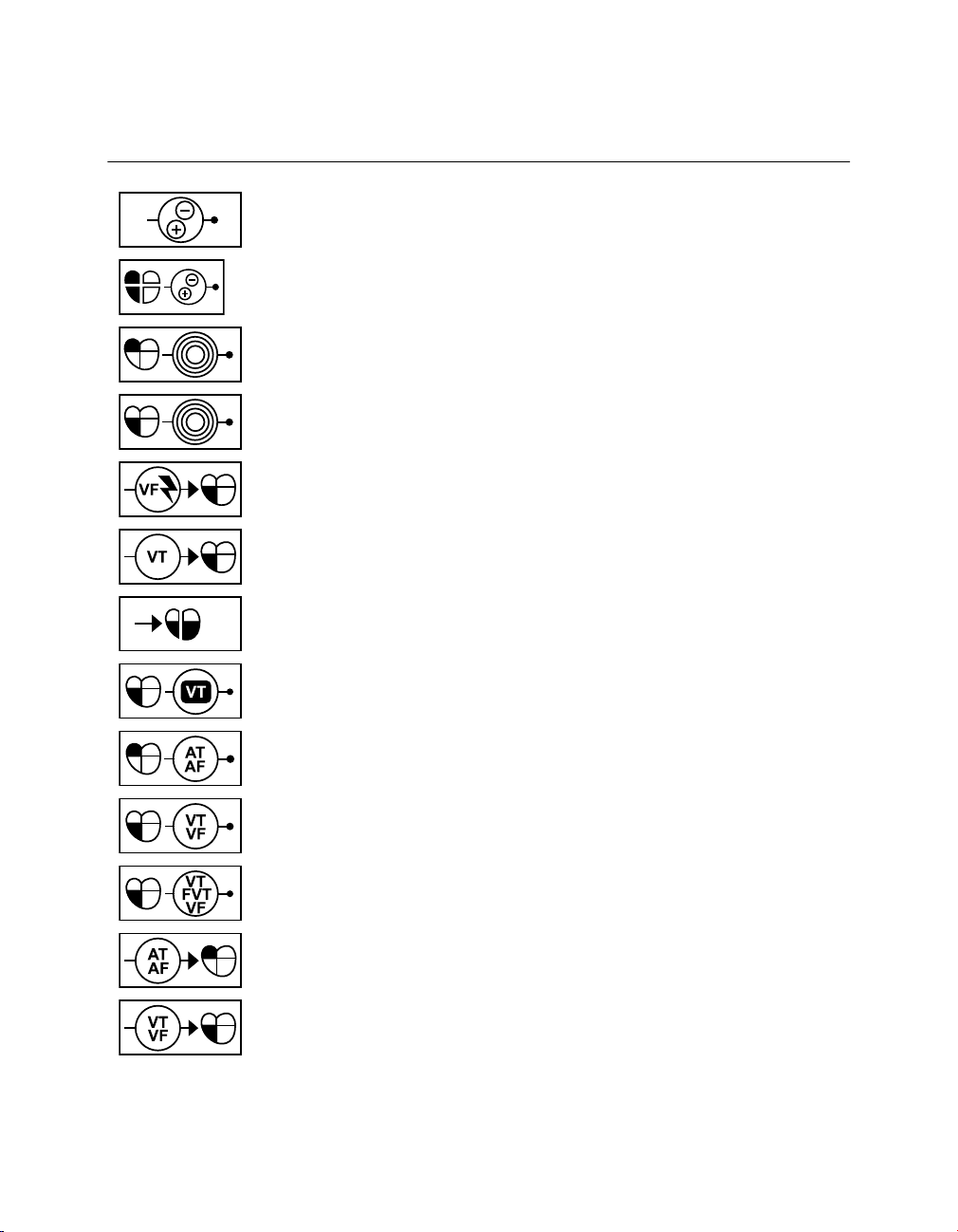
Table 1. Explanation of symbols on package labeling
Symbol Explanation
Conformité Européenne (European Conformity). This symbol means that
the device fully complies with AIMD Directive 90/385/EEC (NB 0123) and
R&TTE Directive 1999/5/EC.
This symbol means that the device fully complies with the Australian
Communications and Media Authority (ACMA) and the New Zealand Ministry of Economic Development Radio Spectrum Management standards
for radio communications products.
Radio compliance. This symbol means that telecommunications and
radio communications regulations in your country may apply to this product. Please go to www.medtronic.com/radio for specific compliance information related to telecommunications and radio standards for this product
in your country.
MR Conditional. The SureScan pacing system is safe for use in the MRI
environment when used according to the instructions in the SureScan
technical manual.
Note: Not all devices are MR Conditional.
Caution
Open here
Do not use if package is damaged
Do not reuse
Sterilized using ethylene oxide
Consult instructions for use
For US audiences only
Date of manufacture
Manufacturer
12 Clinician Manual
Page 13
EC REP
Medtronic PROTECTA™ XT DR D314DRG
Table 1. Explanation of symbols on package labeling (continued)
Symbol Explanation
Authorized representative in the European community
Use by
Lot number
Reorder number
Serial number
Temperature limitation
Adaptive
Clinician Manual 13
Package contents
Implantable device
IPG device
Coated (IPG device)
ICD device
Coated (ICD device)
Page 14
Medtronic PROTECTA™ XT DR D314DRG
Table 1. Explanation of symbols on package labeling (continued)
Symbol Explanation
Cardiac resynchronization therapy (CRT) device
Coated (CRT device)
Dual chamber IPG with cardiac resynchronization therapy (CRT-P)
Product documentation
Torque wrench
Accessories
Amplitude/pulse width
Atrial amplitude/pulse width
RV amplitude/pulse width
LV amplitude/pulse width
Upper tracking rate/lower rate
Rate
Lower rate
14 Clinician Manual
Page 15
Medtronic PROTECTA™ XT DR D314DRG
Table 1. Explanation of symbols on package labeling (continued)
Symbol Explanation
Sensitivity
Sensed A-V interval
A-V interval (paced/sensed)
Refractory period
Atrial refractory period
Ventricular refractory period
(PVARP) Post Ventricular Atrial Refractory Period
Polarity
Pacing polarity (single chamber)
Pacing polarity (dual chamber)
LV Pace polarity
Atrial Pace polarity
RV Pace polarity
Clinician Manual 15
Page 16
Medtronic PROTECTA™ XT DR D314DRG
Table 1. Explanation of symbols on package labeling (continued)
Symbol Explanation
Sensing polarity (single chamber)
Sensing polarity (dual chamber)
Atrial sensitivity
Ventricular sensitivity
VF therapies (delivered/stored)
VT therapies
V pacing/V-V pace delay
VT monitor
AT/AF detection
VT, VF detection
VT, FVT, VF detection
AT/AF therapies
VT, VF therapies
16 Clinician Manual
Page 17
Medtronic PROTECTA™ XT DR D314DRG
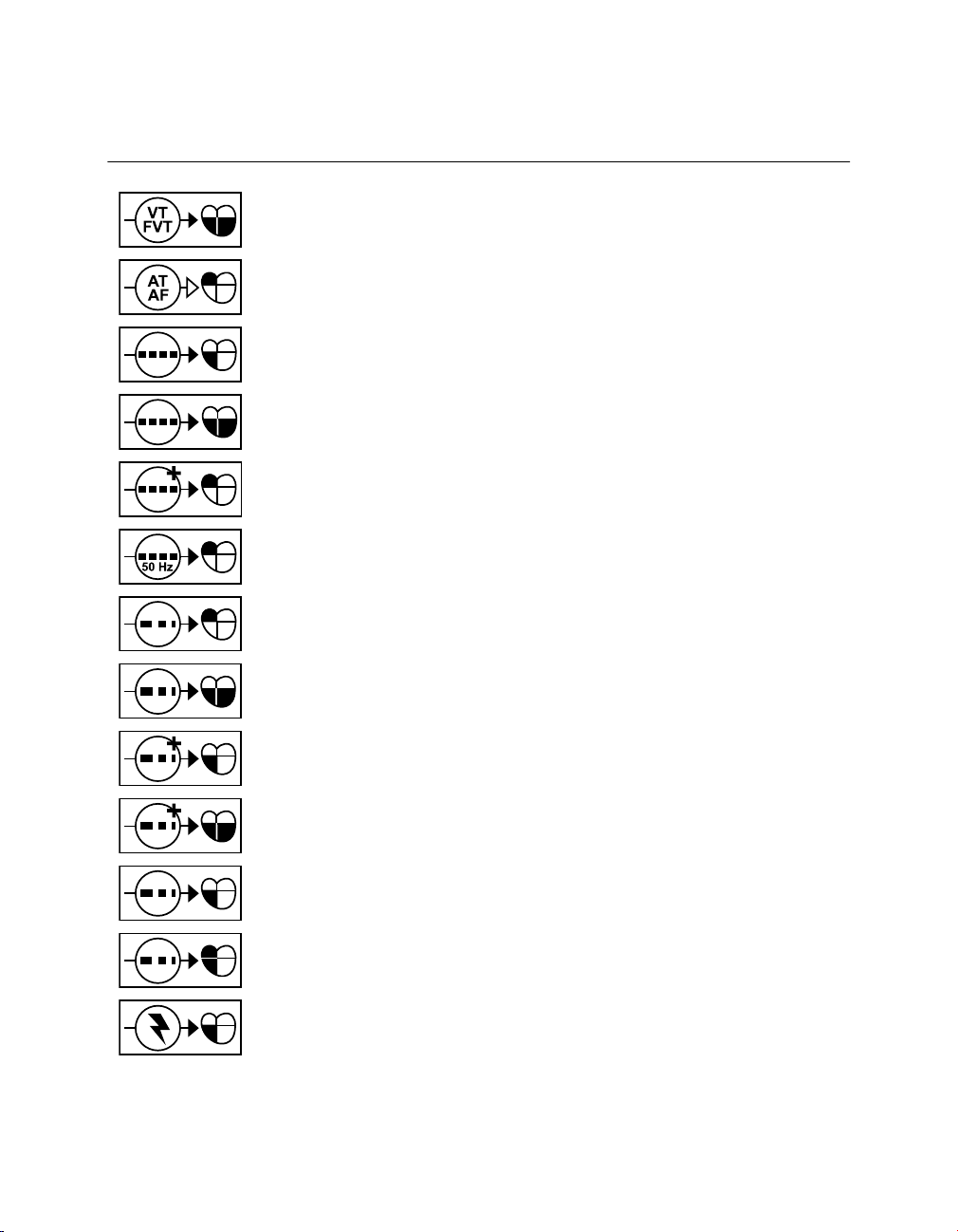
Table 1. Explanation of symbols on package labeling (continued)
Symbol Explanation
VT, FVT therapies (CRT)
AT/AF intervention
Burst
Burst (CRT)
Burst+
50 Hz Burst
A ramp
Ramp (CRT)
Ramp+
Ramp+ (CRT)
V ramp
AV ramp
Defibrillation
Clinician Manual 17
Page 18
Medtronic PROTECTA™ XT DR D314DRG
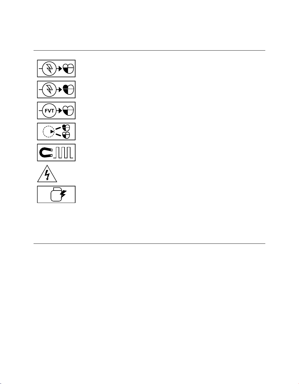
Table 1. Explanation of symbols on package labeling (continued)
Symbol Explanation
V cardioversion
AV cardioversion
FVT therapies
Mode Switch
Magnet Rate
Dangerous voltage
Active Can
TR Triple chamber rate responsive pacemaker
DR Dual chamber rate responsive pacemaker
D Dual chamber pacemaker
SR Single chamber rate responsive pacemaker
S Single chamber pacemaker
1.1.6 Notice
The Patient Information screen of the programmer software application is provided as an
informational tool for the end user. The user is responsible for accurate input of patient
information into the software. Medtronic makes no representation as to the accuracy or
completeness of the patient information that end users enter into the Patient Information
screen. Medtronic SHALL NOT BE LIABLE FOR ANY DIRECT, INDIRECT, INCIDENTAL,
OR CONSEQUENTIAL DAMAGES TO ANY THIRD PARTY WHICH RESULT FROM THE
USE OF THE PATIENT INFORMATION SUPPLIED BY END USERS TO THE SOFTWARE.
For more information about the Patient Information screen, see Section 4.10.
18 Clinician Manual
Page 19

Medtronic PROTECTA™ XT DR D314DRG
1.2 System description
The Medtronic Model D314DRG Protecta XT DR dual chamber implantable cardioverter
defibrillator (ICD) is a multiprogrammable cardiac device that monitors and regulates the
patient’s heart rate by providing single or dual chamber rate-responsive bradycardia pacing,
ventricular tachyarrhythmia therapies, and atrial tachyarrhythmia therapies.
The device senses the electrical activity of the patient’s heart using the electrodes of the
implanted atrial and right ventricular leads. It then analyzes the heart rhythm based on
selectable detection parameters.
The device can automatically detect ventricular tachyarrhythmias (VT/VF) and provides
treatment with defibrillation, cardioversion, and antitachycardia pacing therapies. The
device can also automatically detect atrial tachyarrhythmias (AT/AF) and provides
treatment with cardioversion and antitachycardia pacing therapies. The device responds to
bradyarrhythmias by providing bradycardia pacing therapy.
The device also provides diagnostic and monitoring information that assists with system
evaluation and patient care.
Leads – The lead system used with this device must provide sensing, pacing and
cardioversion/defibrillation therapies to the right ventricle (RV) and sensing and pacing to
the atrium (A). Do not use any lead with this device without first verifying lead and connector
compatibility.
For information about selecting and implanting leads for this device, refer to Section 5.2,
“Selecting and implanting the leads”, page 111.
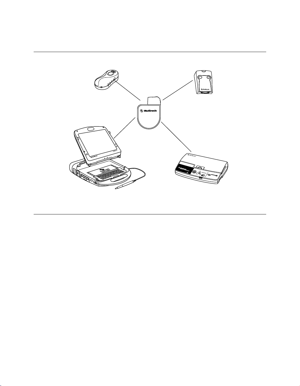
Implantable device system – The Model D314DRG Protecta XT DR along with pacing
leads and defibrillation leads constitute the implantable portion of the device system. The
following figure shows the major components that communicate with the implantable device
system.
Clinician Manual 19
Page 20
VVI
Medtronic CareLink Programmer and
Analyzer
Conexus Activator
Medtronic CareLink Monitor
Implantable device
system
InCheck Patient
Assistant
AF?
Clinic
Home
Medtronic PROTECTA™ XT DR D314DRG
Figure 1. System components
Programmers and software – The Medtronic CareLink Model 2090 Programmer and
software are used to program this device. The Medtronic CareLink Model 2090 Programmer
with Conexus wireless telemetry is designed to provide clinicians and patients with an easy
and efficient implant, follow-up, and monitoring experience. Conexus wireless telemetry
eliminates the need to have a programming head placed over the implanted device for the
duration of a programming or monitoring session. The system uses radio frequency (RF)
telemetry for wireless communication between the implanted device and programmer in the
hospital or clinic. Conexus telemetry operates within the Medical Implant Communications
Service (MICS) Band, which is the only band designated for implantable medical devices.
Using the MICS Band prevents interference with home electronics such as microwaves,
cell phones, and baby monitors.
To turn on Conexus telemetry in an implanted device, you must use the Conexus Activator
or the programming head. If you do not use the Conexus Activator or if you are using a
programmer with nonwireless telemetry, you will need to use the programming head to both
initiate and conduct communications with the device in the clinic.
20 Clinician Manual
Page 21

Medtronic PROTECTA™ XT DR D314DRG
During a wireless telemetry session, all other programmers are prevented from
communicating or initiating a session with the patient’s implanted device, maintaining
patient safety and privacy. Similarly, other patients with implanted devices are not affected
by any communication or programming occurring during the patient’s session.
Programmers from other manufacturers are not compatible with Medtronic devices but will
not damage Medtronic devices.
Model 27901 Conexus Activator – The Medtronic Model 27901 Conexus Activator allows
you to turn on Conexus wireless telemetry for implanted devices that support wireless
telemetry. The Conexus Activator is used in conjunction with the Medtronic CareLink Model
2090 Programmer with Conexus telemetry in the hospital or clinic.
Model 2290 Analyzer – The system supports the use of the Medtronic CareLink Model
2290 Analyzer, an accessory of the Medtronic CareLink programmer. The system allows
you to have a device session and an analyzer session running at the same time, to quickly
switch from one to the other without having to end or restart sessions, and to send data from
the analyzer to the programmer.
Model 2490C Medtronic CareLink Monitor – Patients use the Model 2490C monitor to
automatically gather information from their implanted device and communicate the
information to their physician. The monitor communicates wirelessly with the patient’s
device and transmits the information over a home telephone line at times scheduled by the
clinic. Typically, these transmissions are scheduled while the patient is asleep. The monitor
can also send Medtronic CareAlert Notifications to the clinic outside of the scheduled
transmission times, if the device has been programmed to do so. The patient does not need
to interact with the monitor other than performing the initial setup procedure. Refer to the
monitor literature for connection and usage information.
Model 2696 InCheck Patient Assistant – Patients can use the Model 2696 InCheck
Patient Assistant to perform the following tasks:
●
Initiate recording of cardiac event data in the device memory. Cardiac event data can
be viewed either on the programmer or using CareLink. In addition, when the InCheck
Patient Assistant is activated, the EGM signals of the programmed EGM sources and
markers are stored in the device and are available for review using CareLink. The
CareLink monitor transmits the EGM data and markers from the patient’s device to the
CareLink Network. You can identify patients who have new, not previously viewed
patient-activated episodes and then proceed to view their EGM data using the Detailed
EGM Viewer on CareLink.
●
Verify whether the implanted device has detected a suspected atrial tachyarrhythmia.
●
Request delivery of atrial cardioversion therapy (if the device is programmed to allow
patient-activated cardioversion).
Clinician Manual 21
Page 22

Medtronic PROTECTA™ XT DR D314DRG
Note: Patient-activated cardioversion is delivered only if the implanted device is
currently detecting an AT/AF episode and the physician has programmed the device to
allow patient-activated cardioversion.
Contents of sterile package – The package contains one implantable cardioverter
defibrillator, one torque wrench, and one DF-1 pin plug.
1.3 Indications and usage
The Protecta XT DR system is indicated to provide ventricular antitachycardia pacing and
ventricular defibrillation for automated treatment of life-threatening ventricular arrhythmias.
In addition, the device is indicated for use in patients with atrial tachyarrhythmias, or those
patients who are at significant risk of developing atrial tachyarrhythmias.
Notes:
●
The use of the device has not been demonstrated to decrease the morbidity related to
atrial tachyarrhythmias.
●
The effectiveness of high-frequency burst pacing (atrial 50 Hz Burst therapy) in
terminating device classified atrial tachycardia (AT) was found to be 17%, and in
terminating device classified atrial fibrillation (AF) was found to be 16.8%, in the VT/AT
patient population studied.
●
The effectiveness of high-frequency burst pacing (atrial 50 Hz Burst therapy) in
terminating device classified atrial tachycardia (AT) was found to be 11.7%, and in
terminating device classified atrial fibrillation (AF) was found to 18.2% in the AF-only
patient population studied.
1.4 Contraindications
The Protecta XT DR system is contraindicated for patients experiencing tachyarrhythmias
with transient or reversible causes including, but not limited to, the following: acute
myocardial infarction, drug intoxication, drowning, electric shock, electrolyte imbalance,
hypoxia, or sepsis.
The device is contraindicated for patients who have a unipolar pacemaker implanted.
The device is contraindicated for patients with incessant VT or VF.
The device is contraindicated for patients whose primary disorder is chronic atrial
tachyarrhythmia with no concomitant VT or VF.
22 Clinician Manual
Page 23

Medtronic PROTECTA™ XT DR D314DRG
2 Warnings, precautions, and potential adverse events
2.1 General warnings and precautions
Anti-coagulation – Use of the device should not change the application of established
anti-coagulation protocols.
Avoiding shock during handling – Disable tachyarrhythmia detection during implant,
explant, or postmortem procedures. The device can deliver a high-voltage shock if the
defibrillation terminals are touched.
Electrical isolation during implant – Do not allow the patient to have contact with
grounded electrical equipment that might produce electrical current leakage during implant.
Electrical current leakage may induce tachyarrhythmias that may result in the patient’s
death.
External defibrillation equipment – Keep external defibrillation equipment nearby for
immediate use whenever tachyarrhythmias are possible or intentionally induced during
device testing, implant procedures, or post-implant testing.
Lead compatibility – Do not use another manufacturer’s leads without demonstrated
compatibility with Medtronic devices. If a lead is not compatible with a Medtronic device,
the result may be undersensing of cardiac activity, failure to deliver necessary therapy, or
a leaking or intermittent electrical connection.
Occurrence of stroke – Following an ischemic or cerebrovascular accident, disable atrial
cardioversion therapies until the patient has stabilized.
2.2 Explant and disposal
Consider the following information related to device explant and disposal:
●
Interrogate the device and disable tachyarrhythmia detection before explanting,
cleaning, or shipping the device. This prevents the device from delivering unwanted
shocks.
●
Explant the implantable device postmortem. In some countries, explanting
battery-operated implantable devices is mandatory because of environmental
concerns; please check the local regulations. In addition, if subjected to incineration or
cremation temperatures, the device may explode.
Clinician Manual 23
Page 24

Medtronic PROTECTA™ XT DR D314DRG
●
Medtronic implantable devices are intended for single use only. Do not resterilize and
reimplant explanted devices.
●
Please use the Tachyarrhythmia Product Information Report to return explanted
devices to Medtronic for analysis and disposal.
2.3 Handling and storage instructions
Carefully observe these guidelines when handling or storing the device.
2.3.1 Device handling
Checking and opening the package – Before opening the sterile package tray, visually
check for any signs of damage that might invalidate the sterility of the package contents.
If the package is damaged – The device packaging consists of an outer tray and inner
tray. Do not use the device or accessories if the outer packaging tray is wet, punctured,
opened, or damaged. Return the device to Medtronic because the integrity of the sterile
packaging or the device functionality may be compromised. This device is not intended to
be resterilized.
Sterilization – Medtronic has sterilized the package contents with ethylene oxide before
shipment. This device is for single use only and is not intended to be resterilized.
Device temperature – Allow the device to reach room temperature before it is programmed
or implanted. Device temperature above or below room temperature may affect initial device
function.
Dropped device – Do not implant the device if it has been dropped on a hard surface from
a height of 30 cm (12 in) or more after it is removed from its packaging.
“Use by” date – Do not implant the device after the “Use by” date because the battery
longevity could be reduced.
For single use only – Do not resterilize and reimplant an explanted device.
2.3.2 Device storage
Avoid magnets – To avoid damaging the device, store the device in a clean area away
from magnets, kits containing magnets, and any sources of electromagnetic interference.
Temperature limits – Store and transport the package between –18 °C and +55 °C (0 °F
and 131 °F). Electrical reset may occur at temperatures below –18 °C (0 °F). Device
longevity may decrease and performance may be affected at temperatures above +55 °C
(131 °F).
24 Clinician Manual
Page 25

Medtronic PROTECTA™ XT DR D314DRG
2.4 Lead evaluation and lead connection
Refer to the lead technical manuals for specific instructions and precautions about lead
handling.
Hex wrench – Use only the torque wrench supplied with the device. The torque wrench is
designed to prevent damage to the device from overtightening a setscrew. Other torque
wrenches, (for example a blue-handled or right-angled hex wrench) have torque capabilities
greater than the lead connector can tolerate.
Lead connection – Consider the following information when connecting the lead and the
device:
●
Cap abandoned leads to avoid transmitting electrical signals.
●
Plug any unused lead ports to protect the device.
●
Verify lead connections. Loose lead connections may result in inappropriate sensing
and failure to deliver arrhythmia therapy.
Lead Impedance – Consider the following information about lead impedance when
evaluating the lead system:
●
Ensure that the defibrillation lead impedance is greater than 20 Ω. An impedance of
less than 20 Ω may damage the device or prevent delivery of high-voltage therapy.
●
Before taking electrical or defibrillation efficacy measurements, move objects made
from conductive materials, such as guide wires, away from all electrodes. Metal objects,
such as guide wires, can short circuit a device and lead, causing electrical current to
bypass the heart and possibly damage the device and lead.
Patch leads – Do not fold, alter, or remove any portion of a patch lead. Doing so may
compromise electrode function or longevity.
2.5 Device operation
Accessories – Use this device only with accessories, parts subject to wear, and disposable
items that have been tested to technical standards and found safe by an approved testing
agency.
Atrial Capture Management – Atrial Capture Management does not adjust atrial outputs
to values greater than 5.0 V or 1.0 ms. If the patient needs atrial pacing output greater than
5.0 V or 1.0 ms, manually program the atrial amplitude and pulse width. If a lead dislodges
partially or completely, Atrial Capture Management may not prevent loss of capture.
Battery depletion – Carefully monitor battery longevity by checking battery voltage and
replacement indicators. Battery depletion eventually causes the device to stop functioning.
Clinician Manual 25
Page 26

Medtronic PROTECTA™ XT DR D314DRG
Cardioversion and defibrillation are high-energy therapies that shorten battery longevity. An
excessive number of charging cycles also shortens battery longevity.
Charge Circuit Timeout or Charge Circuit Inactive – Contact a Medtronic representative
and replace the device immediately if the programmer displays a Charge Circuit Timeout
or Charge Circuit Inactive message. If this message is displayed, high-voltage therapies
are not available for the patient.
Concurrent pacemaker use – If a separate pacemaker is used concurrently with the ICD,
verify that the ICD does not sense the pacemaker output pulses because this can affect the
detection of tachyarrhythmias by the ICD. Program the pacemaker to deliver pacing pulses
at intervals longer than the ICD tachyarrhythmia detection intervals.
Device status indicators – If any of the device status indicators (for example, Electrical
Reset) are displayed on the programmer after interrogating the device, inform a Medtronic
representative immediately. If these device status indicators are displayed, therapies may
not be available to the patient.
Electrical reset – Electrical reset can be caused by exposure to temperatures below –18 °C
(0 °F) or strong electromagnetic fields. Advise patients to avoid strong electromagnetic
fields. Observe temperature storage limits to avoid exposure of the device to cold
temperatures. If a partial reset occurs, pacing resumes in the programmed mode with many
of the programmed settings retained. If a full reset occurs, the device operates in VVI mode
at 65 bpm. Electrical reset is indicated by a programmer warning message that is displayed
immediately upon interrogation. To restore the device to its previous operation, it must be
reprogrammed. Inform a Medtronic representative if your patient’s device has reset.
End of Service (EOS) indicator – Replace the device immediately if the programmer
displays an EOS indicator. The device may soon lose the ability to pace, sense, and deliver
therapy adequately.
Follow-up testing – Consider the following information when performing follow-up testing
of the device:
●
Keep external defibrillation equipment nearby for immediate use. Potentially harmful
spontaneous or induced tachyarrhythmias may occur during device testing.
●
Changes in the patient’s condition, drug regimen, and other factors may change the
defibrillation threshold (DFT), preventing the device from terminating the patient’s
tachyarrhythmias postoperatively. Successful termination of ventricular fibrillation or
ventricular tachycardia during the implant procedure is no assurance that
tachyarrhythmias can be terminated postoperatively.
Higher than programmed energy – The device may deliver a therapy of higher than
programmed energy if it was previously charged to a higher energy and that charge remains
on the capacitors.
26 Clinician Manual
Page 27

Medtronic PROTECTA™ XT DR D314DRG
Magnets – Positioning a magnet over the device suspends tachyarrhythmia detection but
does not alter bradycardia therapy. If you place a programming head over the device during
a wireless telemetry session, the magnet in the programming head always suspends
tachyarrhythmia detection. If you place a programming head over the device and establish
a nonwireless telemetry session, tachyarrhythmia detection is not suspended.
Pacemaker-mediated tachycardia (PMT) intervention – Even with the PMT Intervention
feature programmed to On, PMTs may still require clinical intervention, such as device
reprogramming, drug therapy, or lead evaluation.
Pacing and sensing safety margins – Lead maturation (at least one month after implant)
may cause sensing amplitudes to decrease and pacing thresholds to increase, which can
cause undersensing or a loss of capture. Provide an adequate safety margin when selecting
values for pacing amplitude, pacing pulse width, and sensitivity parameters.
Patient safety during a wireless telemetry session – Make sure that you have selected
the appropriate patient before proceeding with a wireless patient session. Maintain visual
contact with the patient for the duration of the session. If you select the wrong patient and
continue with the session, you may inadvertently program the patient’s device to the wrong
settings.
Programmers – Use only Medtronic programmers and application software to
communicate with the device. Programmers and software from other manufacturers are not
compatible with Medtronic devices.
Rate control – Decisions regarding rate controls should not be based on the ability of the
device to prevent atrial arrhythmias.
Rate-responsive modes – Do not program rate-responsive modes for patients who cannot
tolerate rates above the programmed Lower Rate. Rate-responsive modes may cause
discomfort for those patients.
RV Capture Management – RV Capture Management does not program right ventricular
outputs to values greater than 5.0 V or 1.0 ms. If the patient needs right ventricular pacing
output greater than 5.0 V or 1.0 ms, manually program right ventricular amplitude and pulse
width. If a lead dislodges partially or completely, RV Capture Management may not prevent
loss of capture.
Shipping values – Do not use shipping values or nominal values for pacing amplitude and
sensitivity without verifying that the values provide adequate safety margins for the patient.
Single chamber atrial modes – Do not program single chamber atrial modes for patients
with impaired AV nodal conduction. Ventricular pacing does not occur in these modes.
Slow retrograde conduction and PMT – Slow retrograde conduction may induce
pacemaker-mediated tachycardia (PMT) when the VA conduction time is greater than
400 ms. Programming PMT Intervention can help prevent PMT only when the VA conduction
time is less than 400 ms.
Clinician Manual 27
Page 28

Medtronic PROTECTA™ XT DR D314DRG
Testing for cross-stimulation – At implant, and regularly when atrial ATP therapy is
enabled, conduct testing at the programmed atrial ATP output settings to ensure that
ventricular capture does not occur. This is particularly important when the lead is placed in
the inferior atrium.
Twiddler’s syndrome – Twiddler’s syndrome, the tendency of some patients to manipulate
their device after implant, may cause the pacing rate to increase temporarily if the device is
programmed to a rate-responsive mode.
2.5.1 Pacemaker-dependent patients
Ventricular Safety Pacing – Always program Ventricular Safety Pacing (VSP) to On for
pacemaker-dependent patients. Ventricular Safety Pacing prevents ventricular asystole
due to inappropriate inhibition of ventricular pacing caused by oversensing in the ventricle.
ODO pacing mode – Pacing is disabled under ODO pacing mode. Do not program the
ODO mode for pacemaker-dependent patients. Instead, use the Underlying Rhythm Test
to provide a brief period without pacing support.
Underlying Rhythm Test – Use caution when using the Underlying Rhythm Test to inhibit
pacing. The patient is without pacing support when pacing is inhibited.
2.6 Warnings, precautions, and guidance for clinicians
performing medical procedures on cardiac device patients
This section is intended for physicians and other health care professionals who perform
medical procedures on patients with Medtronic implanted cardiac device systems and who
consult with the patients’ cardiologists. This section provides warnings, precautions, and
guidance related to medical therapies and diagnostic procedures that may cause serious
injury to a patient, interfere with a Medtronic implanted cardiac device system, or
permanently damage the system.
Note: Some common medical procedures that pose no risk are also listed in this section.
For additional guidance on medical procedures not addressed in this section, customers
can contact the following resources:
●
Customers in the United States can contact either of the following telephone numbers:
for pacemakers, contact Medtronic Technical Services at +1 800 505 4636; for ICDs,
contact Medtronic Technical Services at +1 800 723 4636. You may also submit
questions to tshelp@Medtronic.com or your Medtronic representative.
●
Customers outside of the United States can contact a Medtronic representative.
28 Clinician Manual
Page 29

Medtronic PROTECTA™ XT DR D314DRG
Ablation (RF ablation or microwave ablation) – Ablation is a surgical technique in which
radio frequency (RF) or microwave energy is used to destroy cells by creating heat. Ablation
used in cardiac device patients may result in, but is not limited to, induced ventricular
tachyarrhythmias, oversensing, unintended tissue damage, device damage, or device
malfunction.
Pulse-modulated ablation systems may pose higher risk for induced ventricular
tachyarrhythmias. Medtronic cardiac devices are designed to withstand exposure to
ablation energy. To mitigate risks, observe the following precautions:
●
Ensure that temporary pacing and defibrillation equipment is available.
●
Avoid direct contact between the ablation catheter and the implanted system.
●
Position the return electrode patch so that the electrical current pathway does not pass
through or near the device and leads.
●
Always monitor the patient during ablation with at least two separate methods, such as
arterial pressure display, ECG, manual monitoring of the patient’s rhythm (taking pulse)
or monitor by some other means such as ear or finger pulse oximetry, or Doppler pulse
detection.
To avoid or mitigate the effects of oversensing, if appropriate for the patient, initiate
asynchronous pacing by implementing one of the following precautions;
●
Suspend tachyarrhythmia detection by using a magnet or a programmer. If a
programmer is used and ablation causes a device reset, the cardiac device resumes
detection. After the ablation procedure, remove the magnet or restore device
parameters.
●
If appropriate for the patient, program the device to an asynchronous pacing mode (for
example, DOO). After the ablation procedure, remove the magnet or restore device
parameters.
Capsule endoscopy, pH capsule procedures – Capsule endoscopy is a procedure in
which a capsule containing a tiny camera is swallowed by the patient to take pictures of the
patient’s digestive tract. Capsule endoscopy and pH capsule procedures should pose no
risk of electromagnetic interference.
Dental procedures – Dental equipment, such as ultrasonic scalers, drills, and pulp testers,
poses no risk of electromagnetic interference. Keep a cardiac device at least 15 cm (6 in)
away from magnets, such as magnets found in dental office pillow headrests.
Diagnostic radiology (CT scans, fluoroscopy, mammograms, x-rays) – Diagnostic
radiology refers to the following medical procedures:
●
Computed axial tomography (CT or CAT scan)
●
Fluoroscopy (an x-ray procedure that makes it possible to see internal organs in motion
by producing a video image)
Clinician Manual 29
Page 30

Medtronic PROTECTA™ XT DR D314DRG
●
Mammograms
●
X-rays (radiography, such as chest x-rays)
Normally, the accumulated dose from diagnostic radiology is not sufficient to damage the
device. If the device is not directly exposed to the radiation beam, no risk of interference
with device operation occurs. However, if the device is directly in a CT scan beam, see the
following precautions in “CT scan”. Similar interference may be observed for some forms
of high-intensity fluoroscopy.
CT scan – A CT scan is a computerized process in which two-dimensional x-ray images are
used to create a three-dimensional x-ray image. If the device is not directly in the CT scan
beam, the device is not affected. If the device is directly in the CT scan beam, oversensing
may occur for the duration of time the device is in the beam. If the device will be in the beam
for longer than 4 s, to avoid or mitigate the effects of oversensing, if appropriate for the
patient, initiate asynchronous pacing by implementing one of the following precautions:
●
Suspend tachyarrhythmia detection by using a magnet or a programmer. After
completing the CT scan, remove the magnet or restore device parameters.
●
If appropriate for the patient, program the device to an asynchronous pacing mode (for
example, DOO). After completing the CT scan, restore device parameters.
Diagnostic ultrasound – Diagnostic ultrasound is an imaging technique that is used to
visualize muscles and internal organs, their size, structures, and motion as well as any
pathological lesions. It also is used for fetal monitoring and to detect and measure blood
flow. Diagnostic ultrasound, such as echocardiogram, poses no risk of electromagnetic
interference. For precautions about therapeutic ultrasound, see “Diathermy treatment
(including therapeutic ultrasound)”.
Diathermy treatment (including therapeutic ultrasound) – Diathermy is a treatment
that involves the therapeutic heating of body tissues. Diathermy treatments include high
frequency, short wave, microwave, and therapeutic ultrasound. Except for therapeutic
ultrasound, do not use diathermy treatments on cardiac device patients. Diathermy
treatments may result in serious injury or damage to an implanted device and leads.
Therapeutic ultrasound is the use of ultrasound at higher energies than diagnostic
ultrasound to bring heat or agitation into the body. Therapeutic ultrasound is acceptable if
treatment is performed with a minimum separation distance of 15 cm (6 in) between the
applicator and the implanted device and leads.
Electrolysis – Electrolysis is the permanent removal of hair by using an electrified needle
(AC or DC) that is inserted into the hair follicle. Electrolysis introduces electrical current into
the body, which may cause oversensing. Evaluate any possible risks associated with
oversensing with the patient’s medical condition. To avoid or mitigate the effects of
30 Clinician Manual
Page 31

Medtronic PROTECTA™ XT DR D314DRG
oversensing, if appropriate for the patient, initiate asynchronous pacing by implementing
one of the following precautions:
●
Suspend tachyarrhythmia detection by using a magnet or a programmer. After
completing electrolysis, remove the magnet or restore device parameters.
●
If appropriate for the patient, program the device to an asynchronous pacing mode (for
example, DOO). After completing electrolysis, restore device parameters.
Electrosurgery – Electrosurgery (including electrocautery, electrosurgical cautery, and
Medtronic Advanced Energy surgical incision technology) is a process in which an electric
probe is used to control bleeding, to cut tissue, or to remove unwanted tissue. Electrosurgery
used on cardiac device patients may result in, but is not limited to, oversensing, unintended
tissue damage, tachyarrhythmias, device damage, or device malfunction. If electrosurgery
cannot be avoided, consider the following precautions:
●
Ensure that temporary pacing and defibrillation equipment is available.
●
Use a bipolar electrosurgery system or Medtronic Advanced Energy surgical incision
technology, if possible. If a unipolar electrosurgery system is used, position the return
electrode patch so that the electrical current pathway does not pass through or within
15 cm (6 in) of the device and leads.
●
Do not apply unipolar electrosurgery within 15 cm (6 in) of the device and leads.
●
Use short, intermittent, and irregular bursts at the lowest clinically appropriate energy
levels.
●
Always monitor the patient during electrosurgery. If the ECG tracing is not clear due to
interference, manually monitor the patient’s rhythm (take pulse); alternatively, monitor
by some other means such as ear or finger pulse oximetry, Doppler pulse detection, or
arterial pressure display.
To avoid or mitigate the effects of oversensing, consider the following precautions:
●
Suspend tachyarrhythmia detection by using a magnet or a programmer. If a
programmer is used and electrosurgery causes a device reset, the cardiac device
resumes detection. After completing electrosurgery, remove the magnet or restore
device parameters.
●
If appropriate for the patient, program the device to an asynchronous pacing mode (for
example, DOO). After completing electrosurgery, restore device parameters.
External defibrillation and cardioversion – External defibrillation and cardioversion are
therapies that deliver an electrical shock to the heart to convert an abnormal heart rhythm
to a normal rhythm.
Medtronic cardiac devices are designed to withstand exposure to external defibrillation and
cardioversion. While damage to an implanted system from an external shock is rare, the
probability increases with increased energy levels. These procedures may also temporarily
Clinician Manual 31
Page 32

Medtronic PROTECTA™ XT DR D314DRG
or permanently elevate pacing thresholds or temporarily or permanently damage the
myocardium. If external defibrillation or cardioversion are required, consider the following
precautions:
●
Use the lowest clinically appropriate energy.
●
Position the patches or paddles a minimum of 15 cm (6 in) away from the device.
●
Position the patches or paddles perpendicular to the device and leads.
●
If an external defibrillation or cardioversion is delivered within 15 cm (6 in) of the device,
use a Medtronic programmer to evaluate the device and lead system.
Hyperbaric therapy (including hyperbaric oxygen therapy, or HBOT) – Hyperbaric
therapy is the medical use of air or 100% oxygen at a higher pressure than atmospheric
pressure. Hyperbaric therapies with pressures exceeding 2.5 ATA (approximately 15 m (50
ft) of seawater) may affect device function or cause device damage. To avoid or mitigate
risks, do not expose implanted devices to pressures exceeding 2.5 ATA.
Lithotripsy – Lithotripsy is a medical procedure that uses mechanical shock waves to break
up kidney or gallbladder stones. If the device is at the focal point of the lithotripter beam,
lithotripsy may permanently damage the device. If lithotripsy is required, keep the focal point
of the lithotripter beam a minimum of 2.5 cm (1 in) away from the device. To avoid or mitigate
the effects of oversensing, consider the following precautions:
●
Suspend tachyarrhythmia detection by using a magnet or a programmer. After
completing lithotripsy treatment, remove the magnet or restore device parameters.
●
If appropriate for the patient, program the device to an asynchronous pacing mode (for
example, DOO). After completing lithotripsy treatment, restore device parameters.
Magnetic resonance imaging (MRI) – An MRI is a type of medical imaging that uses
magnetic fields to create an internal view of the body. Do not conduct MRI scans on patients
who have this device or lead implanted. MRI scans may result in serious injury, induction
of tachyarrhythmias, or implanted system malfunction or damage.
Radiotherapy – Radiotherapy is a cancer treatment that uses radiation to control cell
growth. When performing radiotherapy, take precautions to avoid oversensing, device
damage, and device operational errors, as described in the following sections:
●
Oversensing – If the patient undergoes radiotherapy treatment and the average dose
rate at the device exceeds 1 cGy/min, the device may inappropriately sense direct or
scattered radiation as cardiac activity for the duration of the procedure. To avoid or
mitigate the effects of oversensing, consider these precautions:
– Suspend tachyarrhythmia detection by using a magnet or a programmer. After
completing radiotherapy treatment, remove the magnet or restore device
parameters.
32 Clinician Manual
Page 33

Medtronic PROTECTA™ XT DR D314DRG
– If appropriate for the patient, program the device to an asynchronous pacing mode
(for example, DOO). After completing radiotherapy treatment, restore device
parameters.
●
Device damage – Exposing the device to high doses of direct or scattered radiation from
any source that results in an accumulated dose greater than 500 cGy may damage the
device. Damage may not be immediately apparent. If a patient requires radiation
therapy from any source, do not expose the device to radiation that exceeds an
accumulated dose of 500 cGy. To limit device exposure, use appropriate shielding or
other measures. For patients who are undergoing multiple radiation treatments,
consider the accumulated dose to the device from previous exposures.
Note: Normally, the accumulated dose from diagnostic radiology is not sufficient to
damage the device. See “Diagnostic radiology” for precautions.
●
Device operational errors – Exposing the device to scattered neutrons may cause
electrical reset of the device, errors in device functionality, errors in diagnostic data, or
loss of diagnostic data. To help reduce the chance of electrical reset due to neutron
exposure, deliver radiotherapy treatment by using photon beam energies less than or
equal to 10 MV. The use of conventional x-ray shielding during radiotherapy does not
protect the device from the effects of neutrons. If photon beam energies exceed 10 MV,
Medtronic recommends interrogating the device immediately after radiotherapy
treatment. An electrical reset requires reprogramming of device parameters. Electron
beam treatments that do not produce neutrons do not cause electrical reset of the
device.
Stereotaxis – Stereotaxis is a catheter navigation platform that allows clinicians to steer
catheter-based diagnostic and therapeutic devices throughout the body by using magnetic
navigation. During a stereotaxis procedure, the magnetic field may activate the magnet
detection sensor in the implanted device, which suspends tachyarrhythmia detection. The
device resumes normal programmed operation after the procedure.
Transcutaneous electrical nerve stimulation (TENS) – TENS (including neuromuscular
electrical stimulation or NMES) is a pain control technique that uses electrical impulses
passed through the skin to stimulate nerves. A TENS device is not recommended for
in-home use by cardiac device patients due to a potential for oversensing, inappropriate
therapy, or inhibition of pacing. If a TENS device is determined to be medically necessary,
contact a Medtronic representative for more information.
Transurethral needle ablation (Medtronic TUNA therapy) – Transurethral needle
ablation is a surgical procedure used for benign prostatic hyperplasia (BPH) in which
precisely focused, conducted radio frequency energy is used to ablate prostate tissue.
Patients with implanted cardiac devices may conditionally undergo procedures that use the
Medtronic TUNA system. To avoid affecting cardiac device function when performing the
Clinician Manual 33
Page 34

Medtronic PROTECTA™ XT DR D314DRG
TUNA procedure, position the return electrode on the lower back or lower extremity at least
15 cm (6 in) away from the implanted device and leads.
2.7 Warnings, precautions, and guidance related to
electromagnetic interference (EMI) for cardiac device
patients
Many cardiac device patients resume their normal daily activities after full recovery from
surgery. However, there may be certain situations that patients need to avoid. Because a
cardiac device is designed to sense the electrical activity of the heart, the device may sense
a strong electromagnetic energy field outside of the body and deliver a therapy that is not
needed or withhold a therapy that is needed. The following sections provide important
information to share with patients about electrical equipment or environments that may
cause interference with their implanted cardiac device.
For additional guidance about EMI, customers can contact the following resources:
●
Customers in the United States can contact either of the following telephone numbers:
for pacemakers, contact Medtronic Technical Services at +1 800 505 4636; for ICDs,
contact Medtronic Technical Services at +1 800 723 4636. You may also submit
questions to tshelp@Medtronic.com or your Medtronic representative.
●
Customers outside of the United States can contact a Medtronic representative.
General EMI guidelines for patients – Patients should observe the following general
guidelines regarding EMI:
●
Area restrictions – Before entering an area where signs are posted prohibiting persons
with an implanted cardiac device, such as a pacemaker or ICD, consult with your doctor.
●
Symptoms of EMI – If you become dizzy or feel rapid or irregular heartbeats while using
an electrical item, release whatever you are touching or move away from the item. The
cardiac device should immediately return to normal operation. If symptoms do not
improve when you move away from the item, consult with your doctor. If you have an
ICD and you receive a therapy shock while using an electrical item, release the item or
move away from it, then consult with your doctor.
●
Proper grounding of electrical items – To avoid interference from electrical current that
may leak from improperly grounded electrical items and pass through the body, observe
the following precautions:
– Make sure that all electrical items are properly wired and grounded.
– Make sure that electrical supply lines for swimming pools and hot tubs are properly
installed and grounded according to local and national electrical code requirements.
34 Clinician Manual
Page 35

Medtronic PROTECTA™ XT DR D314DRG
Wireless communication devices – Wireless communication devices include
transmitters that can affect cardiac devices. When using wireless communication devices,
keep them at least 15 cm (6 in) away from your cardiac device. The following items are
examples of such devices:
●
Hand-held cellular, mobile, or cordless telephones (wireless telephones); two-way
pagers; personal digital assistants (PDAs); smartphones; and mobile email devices
●
Wireless-enabled devices such as laptop, notebook, or tablet computers; network
routers; MP3 players; e-readers; gaming consoles; televisions; DVD players; and
headsets
●
Remote keyless entry and remote car starter devices
Household and hobby items with motors or magnets and other items that cause
EMI – Household and hobby items that have motors or magnets or that generate
electromagnetic energy fields could interfere with a cardiac device. Keep a cardiac device
at least 15 cm (6 in) away from the following items:
●
Hand-held kitchen appliances, such as electric mixers
●
Sewing machines and sergers
●
Personal care items, such as corded hand-held hair dryers, corded electric shavers,
electric or ultrasonic toothbrushes (base charger), or back massagers
●
Items that contain magnets, such as bingo wands, mechanic’s extractor wands,
magnetic bracelets, magnetic clasps, magnetic chair pads, or stereo speakers
●
Remote controller of radio-controlled toys
●
Two-way walkie-talkies (less than 3 W)
The following household and hobby items require special precautions:
●
Boat motors – Keep a cardiac device at least 30 cm (12 in) away from electric trolling
motors or gasoline-powered boat motors.
●
Electronic body fat scale – Using this type of scale is not recommended for cardiac
device patients because it passes electricity through the body and can interfere with
the device.
●
Electronic pet fences or invisible fences – Keep a cardiac device at least 30 cm (12 in)
away from the buried wire and the indoor antenna of electronic pet fences or invisible
fences.
●
Home-use electric kilns – Keep a cardiac device at least 60 cm (24 in) away from
home-use electric kilns.
●
Induction cook tops – An induction cook top uses an alternating magnetic field to
generate heat. Keep a cardiac device at least 60 cm (24 in) away from the heating zone
when the induction cook top is turned on.
Clinician Manual 35
Page 36

Medtronic PROTECTA™ XT DR D314DRG
●
Magnetic mattress pads or pillows – Items containing magnets can interfere with the
normal operation of a cardiac device if they are within 15 cm (6 in) of the device. Avoid
using magnetic mattress pads or pillows because they cannot easily be kept away from
the device.
●
Portable electric generators up to 20 kW – Keep a cardiac device at least 30 cm (12 in)
away from portable electric generators.
●
UPS (uninterruptible power source) up to 200 A – Keep a cardiac device at least 30 cm
(12 in) away from a UPS. If the UPS is operating by battery source, keep a cardiac device
at least 45 cm (18 in) away.
Home power tools – Most home power tools should not affect cardiac devices. Consider
the following common-sense guidelines:
●
Keep all equipment in good working order to avoid electrical shock.
●
Be certain that plug-in tools are properly grounded (or double insulated). Using a ground
fault interrupter outlet is a good safety measure (this inexpensive device prevents a
sustained electrical shock).
Some home power tools could affect cardiac device operation. Consider the following
guidelines to reduce the possibility of interference:
●
Electric yard and hand-held power tools (plug-in and cordless) – Keep a cardiac device
at least 15 cm (6 in) away from such tools.
●
Soldering guns and demagnetizers – Keep a cardiac device at least 30 cm (12 in) away
from these tools.
●
Gasoline-powered tools and gasoline-powered yard equipment – Keep a cardiac
device at least 30 cm (12 in) away from components of the ignition system. Turn off the
motor before making adjustments.
●
Car engine repair – Turn off car engines before making any adjustments. When the
engine is running, keep a cardiac device at least 30 cm (12 in) away from components
of the ignition system.
Industrial equipment – After recovering from implant surgery, you likely will be able to
return to work, school, or daily routine. However, if you will be using or working near
high-voltage equipment, sources of high electrical current, magnetic fields, or other EMI
sources that may affect device operation, consult with your doctor. You may need to avoid
using, or working near, the following types of industrial equipment:
●
Electric furnaces used in the manufacturing of steel
●
Induction heating equipment and induction furnaces, such as kilns
●
Industrial magnets or large magnets, such as those used in surface grinding and
electromagnetic cranes
36 Clinician Manual
Page 37

Medtronic PROTECTA™ XT DR D314DRG
●
Dielectric heaters used in industry to heat plastic and dry glue in furniture manufacturing
●
Electric arc and resistance welding equipment
●
Broadcasting antennas of AM, FM, shortwave radio, and TV stations
●
Microwave transmitters. Note that microwave ovens are unlikely to affect cardiac
devices.
●
Power plants, large generators, and transmission lines. Note that lower voltage
distribution lines for homes and businesses are unlikely to affect cardiac devices.
Radio transmitters – Determining a safe distance between the antenna of a radio
transmitter and a cardiac device depends on many factors such as transmitter power,
frequency, and the antenna type. If the transmitter power is high or if the antenna cannot be
directed away from a cardiac device, you may need to stay farther away from the antenna.
Refer to the following guidelines for different types of radio transmitters:
●
Two-way radio transmitter (less than 3 W) – Keep a cardiac device at least 15 cm (6 in)
away from the antenna.
●
Portable transmitter (3 to 15 W) – Keep a cardiac device at least 30 cm (12 in) away
from the antenna.
●
Commercial and government vehicle-mounted transmitters (15 to 30 W) – Keep a
cardiac device at least 60 cm (24 in) away from the antenna.
●
Other transmitters (125 to 250 W) – Keep a cardiac device at least 2.75 m (9 ft) away
from the antenna.
For transmission power levels higher than 250 W, contact a Medtronic representative
for more information.
Security systems – When passing through security systems, follow these precautions:
●
Electronic antitheft systems, such as in a store or library, and point-of-entry control
systems, such as gates or readers that include radio frequency identification
equipment – These systems should not affect a cardiac device, but as a precaution, do
not linger near or lean against such systems. Simply walk through these systems at a
normal pace. If you are near an electronic antitheft or entry control system and
experience symptoms, promptly move away from the equipment. After you move away
from the equipment, the cardiac device resumes its previous state of operation.
●
Airport, courthouse, and jail security systems – Given the short duration of security
screening, it is unlikely that metal detectors (walk-through archways and hand-held
wands) and full body imaging scanners (also called millimeter wave scanners and
three-dimensional imaging scanners) in airports, courthouses, and jails will affect a
cardiac device. When encountering these security systems, follow these guidelines:
– Always carry your cardiac device ID card. If a cardiac device sets off a metal detector
or security system, show your ID card to the security operator.
Clinician Manual 37
Page 38

Medtronic PROTECTA™ XT DR D314DRG
– Minimize the risk of temporary interference with your cardiac device while going
through the security screening process by not touching metal surfaces around any
screening equipment.
– Do not stop or linger in a walk-through archway; simply walk through the archway at
a normal pace.
– If a hand-held wand is used, ask the security operator not to hold it over or wave it
back and forth over your cardiac device.
– If you have concerns about security screening methods, show your cardiac device
ID card to the security operator, request alternative screening, and then follow the
security operator’s instructions.
2.8 Potential adverse events
The potential adverse events associated with the use of transvenous leads and pacing
systems include, but are not limited to, the following events:
●
acceleration of tachyarrhythmias (caused by device)
●
air embolism
●
bleeding
●
body rejection phenomena, including local tissue reaction
●
cardiac dissection
●
cardiac perforation
●
cardiac tamponade
●
chronic nerve damage
●
constrictive pericarditis
●
death
●
device migration
●
endocarditis
●
erosion
●
excessive fibrotic tissue growth
●
extrusion
●
fibrillation or other arrhythmias
●
fluid accumulation
38 Clinician Manual
Page 39

Medtronic PROTECTA™ XT DR D314DRG
●
formation of hematomas/seromas or cysts
●
heart block
●
heart wall or vein wall rupture
●
hemothorax
●
infection
●
keloid formation
●
lead abrasion and discontinuity
●
lead migration/dislodgement
●
mortality due to inability to deliver therapy
●
muscle and/or nerve stimulation
●
myocardial damage
●
myocardial irritability
●
myopotential sensing
●
pericardial effusion
●
pericardial rub
●
pneumothorax
●
poor connection of the lead to the device, which may lead to oversensing, undersensing,
or a loss of therapy
●
threshold elevation
●
thrombotic embolism
●
thrombosis
●
tissue necrosis
●
valve damage (particularly in fragile hearts)
●
venous occlusion
●
venous perforation
Additional potential adverse events associated with the use of ICD systems include, but are
not limited to, the following events:
●
inappropriate shocks
●
potential mortality due to inability to defibrillate
●
shunting current or insulating myocardium during defibrillation
Clinician Manual 39
Page 40

Medtronic PROTECTA™ XT DR D314DRG
Patients susceptible to frequent shocks despite medical management could develop
psychological intolerance to an ICD system that might include the following conditions:
●
dependency
●
depression
●
fear of premature battery depletion
●
fear of shocking while conscious
●
fear that shocking capability may be lost
●
imagined shocking (phantom shock)
40 Clinician Manual
Page 41

Medtronic PROTECTA™ XT DR D314DRG
3 Clinical data
3.1 Adverse events and clinical trial data
Information regarding clinical studies and adverse events related to this device is available
at www.medtronic.com/manuals. To view, download, print, or order the following clinical
studies from the Medtronic website, perform the following steps:
1. Navigate your web browser to http://www.medtronic.com/manuals.
2. Select the hyperlink that corresponds to your location.
3. Select the Search field on the left side of the screen and type “D314DRG”.
4. Click [Search]. All technical literature for this device is listed.
The following clinical studies are related to this device:
Atrial Capture Management (ACM) study – This clinical study, which evaluated the Atrial
Capture Management feature in EnPulse pacemakers, provides support for the Atrial
Capture Management feature in Protecta XT DR Model D314DRG devices.
Atrial Fibrillation Symptoms Mediated by Pacing to Mean Rates (AF SYMPTOMS) –
This study evaluated the long-term effects of Conducted AF Response in patients with atrial
fibrillation and intact atrioventricular (AV) conduction. It provides support for the Conducted
AF Response feature in Protecta XT DR Model D314DRG devices. Note that the Ventricular
Response Pacing (VRP) feature mentioned in the study is called Conducted AF Response
in the Protecta XT DR Model D314DRG devices.
Atrial Septal Pacing Efficacy Trial (ASPECT) – This clinical study, which evaluated the
safety and efficacy of the Medtronic AT500 DDDRP Pacing System devices, provides
support for the atrial intervention pacing therapies.
Atrial Therapy Efficacy and Safety Trial (ATTEST) – This clinical study, which evaluated
the safety and efficacy of the Medtronic AT500 DDDRP Pacing System devices, provides
support for the Protecta XT DR Model D314DRG devices.
The Enhanced Surveillance of Right Ventricle Lead Integrity Alert (RV LIA) – This
study, which prospectively assessed the performance of the Right Ventricle Lead Integrity
Alert, provided an estimate of the probability of receiving a three-day warning for patients
with a lead fracture. The study provides support for the RV Lead Integrity Alert feature in
Protecta XT DR Model D314DRG devices.
EnRhythm clinical study – This clinical study, which evaluated the safety and efficacy of
the EnRhythm Model P1501DR devices, provides support for MVP mode pacing and the
Reactive ATP feature in the Protecta XT DR Model D314DRG devices.
Clinician Manual 41
Page 42

Medtronic PROTECTA™ XT DR D314DRG
EnTrust clinical study – This clinical study, which evaluated the safety and clinical
performance of the EnTrust ICD system, provides support for the Protecta XT DR Model
D314DRG devices.
EnTrust tachyarrhythmia detection performance vs. GEM DR tachyarrhythmia
detection performance – This retrospective evaluation of the EnTrust detection algorithm
was performed on spontaneous rhythms recorded in patients implanted with the GEM DR
ICD. It provided support for the modifications made to the PR Logic Sinus Tachycardia
criterion in the EnTrust devices. These modifications also apply to the Protecta XT DR Model
D314DRG devices.
FAST study – This clinical study, which evaluated the OptiVol Fluid Monitoring feature in
InSync Marquis devices to corroborate the MIDHeFT clinical data, provides support for the
OptiVol Fluid Monitoring feature in Protecta XT DR Model D314DRG devices.
GEM DR clinical studies – This clinical study, which evaluated the appropriateness of dual
chamber sensing and tachyarrhythmia detection during induced and simulated cardiac
arrhythmias in GEM DR devices, provides support for the Protecta XT DR Model D314DRG
devices.
GEM III DR Model 7275 MVP study – This clinical study, which evaluated the performance
of MVP mode pacing in the GEM III DR Model 7275 devices, provides support for MVP
mode in the Protecta XT DR Model D314DRG devices.
InSync III Marquis clinical study – This clinical study, which evaluated the Conducted
AF Response feature in the InSync III Marquis devices, provides support for Conducted AF
Response in Protecta XT DR Model D314DRG devices.
Jewel AF clinical study for AF patients only – This clinical study evaluated the atrial
tachyarrhythmia therapies and dual chamber tachyarrhythmia detection algorithm provided
by Jewel AF Model 7250 devices. The patients included in the study had a primary indication
of atrial fibrillation or atrial flutter. It provides support for atrial tachyarrhythmia therapies and
dual chamber tachyarrhythmia detection in the Protecta XT DR Model D314DRG devices.
Jewel AF clinical study for VT/AT patients – This clinical study evaluated the atrial
tachyarrhythmia therapies and dual chamber tachyarrhythmia detection algorithm provided
by Jewel AF Model 7250 devices. The patients included in the study had a primary indication
of ventricular tachyarrhythmia. Some of the patients in the study also had a history of atrial
tachyarrhythmia. This clinical study provides support for atrial tachyarrhythmia therapies
and dual chamber tachyarrhythmia detection in the Protecta XT DR Model D314DRG
devices.
Kappa 700 clinical study – This study, which evaluated the safety and clinical
performance of the Kappa 700 pacemakers, provides support for the Right Ventricular
Capture Management feature and other bradycardia pacing features.
42 Clinician Manual
Page 43

Medtronic PROTECTA™ XT DR D314DRG
Marquis MVP download study – This clinical study, which evaluated the performance of
MVP mode pacing in the Marquis DR Model 7274 devices, provides support for MVP mode
in the Protecta XT DR Model D314DRG devices.
Marquis VR Single Chamber ICD study – This clinical study, which evaluated the
operation of the Wavelet Auto-Template Algorithm in the Model 7230 Marquis VR devices,
provides support for the Wavelet detection feature in Protecta XT DR Model D314DRG
devices.
Medtronic Impedance Diagnostics in Heart Failure Trial (MIDHeFT) – This clinical
study, which demonstrated the use of intrathoracic impedance as a surrogate measure of
fluid status in patients with heart failure, provides support for the OptiVol Fluid Status
Monitoring feature in Protecta XT DR Model D314DRG devices.
PR Logic with Wavelet performance – This retrospective evaluation was conducted to
demonstrate the safety and performance of the combined PR Logic and Wavelet SVT
discrimination features by assessing the impact to VT/VF detection sensitivity and
specificity of turning Wavelet on in dual chamber ICD and CRT-D devices. This evaluation
provides support for the PR Logic and Wavelet features in Protecta XT DR Model D314DRG
devices.
Protecta detection performance – This retrospective evaluation was performed using
human rhythms collected from various clinical trials and provides support that the addition
of multiple therapy discriminators in the Protecta products do not affect the overall detection
performance of the Protecta XT DR Model D314DRG devices.
Reducing Episodes by Septal Pacing Efficacy Confirmation Trial (RESPECT) – This
clinical study evaluated the efficacy of the intervention pacing therapies on symptomatic
AT/AF episodes in subjects where the lead was placed in the Bachmann’s Bundle region.
The results of the study failed to demonstrate effectiveness of the intervention pacing
therapies. Evaluation of the RESPECT study data indicated that the intervention pacing
features did not significantly reduce the rate of symptomatic AT/AF episodes and these
results did not confirm the findings from previous trials. The pre-specified subgroups were
tested for therapeutic effect, but none had results suggesting benefit. When intervention
pacing algorithms were programmed ON, atrial pacing percentage increased by 18.1%
(P<0.001) with a modest, yet statistically significant, increase in mean heart rate of 2.4 beats
per minute (P<0.001).
RV Lead Integrity Alert retrospective evaluation – This retrospective evaluation
assessed the ability of the RV Lead Integrity Alert feature to provide advance notice of a
Sprint Fidelis lead fracture. The evaluation provides support for the RV Lead Integrity Alert
feature in Protecta XT DR Model D314DRG devices.
RV Lead Noise Discrimination VF detection performance – This retrospective
evaluation was conducted using spontaneous rhythms and provides support that the RV
Clinician Manual 43
Page 44

Medtronic PROTECTA™ XT DR D314DRG
Lead Noise Discrimination algorithm does not impact time to detection in Protecta XT DR
Model D314DRG devices.
Template Matching Morphology (TEMM) study – This clinical study, which evaluated
the functionality of the Template Matching Morphology (TEMM) algorithm, provides support
for the Wavelet detection feature in Protecta XT DR Model D314DRG devices.
TWave Discrimination VF detection performance – This retrospective evaluation was
conducted using induced rhythms and provides support that the TWave Discrimination
algorithm does not impact time to detection in Protecta XT DR Model D314DRG devices.
44 Clinician Manual
Page 45

Medtronic PROTECTA™ XT DR D314DRG
4 Using the programmer
4.1 Establishing telemetry between the device and the
programmer
You can establish telemetry between the device and the programmer by using either a
wireless telemetry mode or a nonwireless telemetry mode.
●
The Medtronic CareLink Model 2090 Programmer with Conexus telemetry supports
patient sessions using either Conexus wireless telemetry or nonwireless telemetry
using a programming head.
●
The Medtronic CareLink Model 2090 Programmer supports patient sessions with
nonwireless telemetry using a programming head.
Refer to the programmer reference guide for information about setting up the programmer
for a patient session.
4.1.1 Using Conexus telemetry
The Medtronic CareLink Model 2090 Programmer with Conexus telemetry is designed to
provide clinicians and patients with an easier and more efficient implant and follow-up
experience. This system uses radio frequency (RF) telemetry for wireless communication
between the implanted device and the programmer in the hospital or clinic. Conexus
telemetry operates within the Medical Implant Communications Service (MICS) band, which
is the only band designated for implantable medical devices. Using the MICS band prevents
interference with home electronics such as microwaves, cell phones, and baby monitors.
Conexus telemetry eliminates the need to have a programming head over the implanted
device for the duration of a programming or follow-up session. At implant, the system allows
you to program the device without having to use a programming head in the sterile field.
See Figure 2.
Clinician Manual 45
Page 46

Medtronic PROTECTA™ XT DR D314DRG
Figure 2. Using Conexus telemetry at implant
During programming and follow-up sessions, the system allows wireless communication
between the device and programmer. See Figure 3.
46 Clinician Manual
Page 47

Medtronic PROTECTA™ XT DR D314DRG
Figure 3. Using Conexus telemetry at a follow-up session
4.1.1.1 Considerations for using Conexus telemetry
When you start a patient session using either wireless or nonwireless telemetry, you must
end the session before changing telemetry modes. The programmer does not operate
simultaneously in wireless and nonwireless telemetry modes.
4.1.1.2 How to activate wireless telemetry
To use Conexus telemetry for a patient session, you need to activate wireless telemetry in
both the programmer and the device.
●
To activate wireless telemetry in the programmer, turn the programmer power on. The
programmer starts and the Find Patient window is displayed. Select the “Allow wireless
communication” check box on the Find Patient window. The programmer searches for
compatible activated devices within telemetry range.
●
To activate wireless telemetry in the device, briefly place the programming head or
Conexus Activator over the device until the device is identified.
Clinician Manual 47
Page 48

Medtronic PROTECTA™ XT DR D314DRG
Upon activation, the programmer searches for activated devices within telemetry range. If
a device senses a signal from the programmer, it sends a signal to the programmer and
remains active for 15 min. The programmer then establishes communication with the
device. The Find Patient window is displayed for at least 5 min. If the programmer touch
pen is not used within 5 min, the Find Patient window closes and the Select Model screen
is displayed.
4.1.1.3 How to use the Find Patient window
The programmer lists all patients with wireless-activated implantable devices within
telemetry range in the Patient Name list within the Find Patient window. Patients are listed
in the order in which they were found by the programmer. The list periodically updates to
include patients with newly activated devices and removes patients with devices that are
no longer active, but the order in which the remaining patients appear in the Patient Name
list does not change. The Find Patient window lists patients for whom a session has not
started or has ended.
4.1.1.4 How to verify reliable telemetry between the device and the
programmer
Successful interrogation or programming of the device verifies that reliable telemetry
between the device and the programmer has occurred. When wireless telemetry is first
established during a session, the telemetry status indicator in the upper-left corner of the
programmer task bar changes from the programming head icon to the wireless telemetry
icon shown in Figure 4.
Figure 4. Wireless telemetry icon on the task bar
1 Wireless telemetry icon
The indicator bar on the wireless telemetry icon displays the strength of the wireless
communication signal. Verify that at least 3 of the green lights are illuminated on the indicator
bar to ensure that reliable telemetry has been established between the implanted device
and the programmer.
48 Clinician Manual
Page 49

Medtronic PROTECTA™ XT DR D314DRG
4.1.1.5 How to maintain reliable telemetry
You can expect reliable wireless telemetry between the implanted device and the
programmer in a typical examination room or operating room. If the device and programmer
are in the presence of other electrical equipment, the system is designed to maintain
effective communication at distances up to 2 m (6.5 feet) between the device and the
programmer. The system should not interfere with other electronic equipment in the area.
If you are having trouble maintaining consistent, reliable telemetry between a patient’s
implanted device and the programmer, take one or more of the following actions to increase
the number of illuminated lights on the telemetry status indicator:
●
Adjust the angle of the programmer screen. The telemetry antenna is part of the
programmer display screen structure, and slight movements of the screen may improve
the telemetry link.
●
Change the position of the programmer so that the space between the programmer
screen and the patient is relatively free of obstruction. The optimal position for the
programmer is between the patient and you, so that you are facing the screen and the
patient is beyond the screen facing both you and the programmer.
●
Shorten the distance between the programmer and the patient.
●
Signal strength may be stronger with the device placed in the patient than if the device
is in the packaging.
●
Remove any sources of electromagnetic interference (EMI) that may be affecting the
telemetry signal.
If a session is accidently disrupted by electrical interference, the programmer attempts to
reestablish communication with the device for the next 5 min. If communication between
the device and programmer is not reestablished during that period, you must use the
Conexus Activator or programming head to reactivate wireless telemetry in the device to
resume or to start a new session.
Note: If you want to use Holter Telemetry to transmit EGM and Marker Channel data during
a Conexus telemetry session, you must first activate Standby mode.
Clinician Manual 49
Page 50

Medtronic PROTECTA™ XT DR D314DRG
4.1.1.6 Session inactivity safeguards
If you or the patient leaves the proximity of the programmer for a period of time, the system
provides 2 levels of session inactivity safeguards against unintentional programming.
●
In a follow-up session, after 2 min of programmer inactivity (with no screen button
activity), the system displays the patient’s name or ID number and device information
and requires you to confirm that the correct patient is in the follow-up session before
you can process a programming command. You can still interact with the programmer
during this time, but you must confirm any programming and interrogating requests.
●
In either an implant or follow-up session, after 2 hours of programmer inactivity (with no
screen button activity) the device transitions to Standby mode.
Standby mode – The system provides a Standby mode for situations in which a period of
inactivity in a patient session is planned. In Standby mode, the device operates in a manner
similar to that in nonwireless telemetry when the programming head is lifted from the device.
Live waveforms are turned off, and the programmer telemetry status indicator shows that
there is no telemetry link. A low level of communication is maintained between the device
and the programmer.
Programmer functions are limited in Standby mode. When the system is in Standby mode
it is possible to start a session with the device, either using the current programmer or
another. If another programmer is used to open a session with the device, end the session
with the current programmer first as the device can be in a session with only one programmer
at a time. Before you attempt to program, interrogate, or conduct testing or emergency
actions, you must verify that the session you are initiating is with the intended patient.
If desired, you can manually activate and deactivate Standby mode.
●
To activate Standby mode, select the wireless telemetry icon in the upper-left corner of
the programmer display.
●
To deactivate Standby mode, reselect the wireless telemetry icon in the upper-left
corner of the programmer display, or place either the Conexus Activator or the
programming head over the device. After 5 min in Standby mode, wireless telemetry is
deactivated within the device and must be reactivated by using either the Conexus
Activator or the programming head.
Note: Standby mode is also deactivated when you attempt to program parameters,
interrogate the device, or conduct testing or emergency operations. The programmer
screen displays the Verify Patient warning window. To deactivate Standby mode and
resume your patient session, verify that the session is with the intended patient, select
the “Allow wireless communication” check box, and select [Continue].
50 Clinician Manual
Page 51

Medtronic PROTECTA™ XT DR D314DRG
4.1.1.7 How to maintain patient safety and privacy
To maintain the patient’s safety and privacy during a wireless telemetry session, all other
programmers are locked out from communicating or initiating a session with the patient’s
implanted device. Similarly, implanted devices in other patients are locked out from any
communication or programming occurring during the patient’s session.
When you are using wireless telemetry, the patient’s name is displayed on the Command
bar of the programmer screen. For more information regarding the Command bar, see
Section 4.3, “Display screen features”, page 57. If the patient’s name has not been
entered, the patient’s ID number is displayed. If the patient’s name and ID number are not
entered, then “(Patient name not entered)” appears on the Command bar. Enter the patient’s
name and ID number as early as possible to assist with patient identification when using
wireless telemetry.
4.1.2 Using nonwireless telemetry
You can use either the Medtronic CareLink Model 2090 Programmer with Conexus
telemetry in nonwireless telemetry mode or the Medtronic CareLink Model 2090
Programmer. You also need to use a Medtronic Model 2067 or 2067L Programming Head
while in this mode. After you start a patient session using nonwireless telemetry, you must
end the session before you can change to wireless telemetry mode.
4.1.2.1 How to establish nonwireless telemetry
If you are using the Medtronic CareLink Model 2090 Programmer with Conexus telemetry
but choose to use it in the nonwireless mode, make sure that the “Allow wireless
communication” check box on the Find Patient window is not selected. This prevents the
programmer from initiating a wireless telemetry session. If you are using a Medtronic
CareLink Model 2090 Programmer that does not have Conexus telemetry, the check box
does not appear on the Find Patient window. Place the programming head over the device
to establish nonwireless telemetry between the programmer and the device. Successful
interrogation or programming of the device verifies that reliable communication between
the device and the programmer has occurred. When nonwireless telemetry is first
established during a session, the telemetry status indicator in the upper-left corner of the
programmer task bar displays the programming head icon, as shown in Figure 5.
Figure 5. Programming head icon on the task bar
1 Programming head icon
Clinician Manual 51
Page 52

Medtronic PROTECTA™ XT DR D314DRG
Note: The programming head contains a magnet that can suspend tachyarrhythmia
detection. When telemetry between the device and programmer is established, detection
is not suspended.
When the programming head is placed over the device and telemetry is established, the
amber light on the programming head turns off, and 1 or more of the green indicator lights
on the programming head illuminate. You can find the optimal position for the programming
head by moving it around the implanted device until the greatest number of green lights
illuminate. Position the programming head so at least 2 of the green lights illuminate in order
to ensure proper telemetry has been established. If the programming head slides off the
patient, the session does not terminate. Place the programming head back over the device
to resume programming or interrogating the device.
Note: More information about the general use of the programming head is available in the
programmer reference guide.
4.2 Conducting a patient session
The programmer interrogates the patient’s device at the start of a patient session. Because
the programmer collects and stores data on a session-by-session basis, you need to start
a new session for each patient. You must end the previous session before starting a session
with another patient.
4.2.1 Starting a patient session
Caution: A programmer failure (for example, a faulty touch pen) could result in inappropriate
programming or the inability to terminate an action or an activity in process. In the event of
a programmer failure, immediately turn the programmer power off to deactivate telemetry
and terminate any programmer controlled activity in process.
Caution: During a wireless telemetry session, verify that you have selected the appropriate
patient before proceeding with the session, and maintain visual contact with the patient for
the duration of the session. If you select the wrong patient and continue with the session,
you may inadvertently program the wrong patient’s device.
Caution: Do not leave the programmer unattended while a wireless telemetry session is in
progress. Maintain control of the programmer during the session to prevent inadvertent
communication with the patient’s device.
Note: During an initial interrogation, only Emergency programmer functions are available.
52 Clinician Manual
Page 53

Medtronic PROTECTA™ XT DR D314DRG
4.2.1.1 How to start a patient session using wireless telemetry
1. Select [Find Patient…] from the Select Model window.
2. Select the “Allow wireless communication” check box on the Find Patient window.
3. Use the Conexus Activator, or briefly place the programming head over the device to
activate wireless telemetry in the device.
Notes:
●
When the Conexus Activator is used to activate telemetry in the device, the
programmer launches the patient session without suspending tachyarrhythmia
detection. Placing a magnet near the device, however, suspends tachyarrhythmia
detection.
●
When the programming head is used to activate telemetry in the device, the
programmer automatically launches the patient session with tachyarrhythmia
detection suspended. Detection remains suspended as long as the programming
head is over the device. A warning reminds you that tachyarrhythmia detection is
suspended.
4. Select the appropriate patient from the Patient Name list on the Find Patient window.
Note: The programmer lists all patients with wireless-activated implantable devices
within telemetry range.
5. Select [Start].
4.2.1.2 How to start a patient session using nonwireless telemetry
1. Select [Find Patient…] from the Select Model window.
2. If you are using a Medtronic CareLink Model 2090 Programmer with Conexus
telemetry, make sure that the “Allow wireless communication” check box on the Find
Patient window is not selected. If you start a session with the programming head over
the patient’s device and the “Allow wireless communication” check box is selected, the
system initiates a wireless telemetry session and automatically interrogates the device.
If you are using a Medtronic CareLink Model 2090 Programmer that does not have
Conexus telemetry, the “Allow wireless communication” check box does not appear
on the Find Patient window.
3. Place the programming head over the device and the nonwireless session
automatically begins.
Clinician Manual 53
Page 54

Medtronic PROTECTA™ XT DR D314DRG
4.2.2 Device and telemetry effects during a patient session
Tachyarrhythmia detection during a wireless telemetry session – If you place a
programming head over the device, the magnet in the programming head always suspends
tachyarrhythmia detection.
Tachyarrhythmia detection during a nonwireless telemetry session – If you place a
programming head over the device and telemetry is established, the magnet in the
programming head does not suspend tachyarrhythmia detection.
Episodes in progress during a wireless telemetry session – If you attempt to initiate a
patient session when a detected arrhythmia episode is in progress, the device treats the
arrhythmia normally. If telemetry has not been established, the magnet inside the
programming head causes the device to suspend detection when the programming head
is placed over the device.
Episodes in progress during a nonwireless telemetry session – After telemetry has
been established and you position the programming head over the device when a detected
arrhythmia episode is in progress, the device treats the arrhythmia normally. If telemetry
has not been established and you position the programming head over the device, the
magnet inside the programming head causes the device to suspend detection.
Capacitor charging during a wireless telemetry session – Interference caused by
capacitor charging may affect telemetry between the device and the programmer. This
could result in a temporary loss of telemetry indicator lights as shown on the programmer
task bar, a temporary loss in Marker transmissions, and temporarily affect the ability to send
programming commands. Ensure that the greatest number of telemetry strength indicator
lights are illuminated on the programmer task bar to help improve telemetry reliability prior
to any manual or automatic capacitor charging.
Capacitor charging during a nonwireless telemetry session – Interference caused by
capacitor charging may affect telemetry between the device and the programmer. The
programming head indicator lights may turn off during charging periods. It is normal for the
lights to turn off on the programming head.
Note: The programming head “P” button is disabled during all EP study and manual system
tests. During tachyarrhythmia inductions, the programming head “I” button is also disabled.
Marker transmissions during a wireless telemetry session – The device continuously
transmits Marker Channel and supplementary marker data while telemetry is established.
The device stops these transmissions when telemetry is interrupted. If Holter Telemetry is
programmed to On, the device transmits telemetry at all times except during a Conexus
telemetry session. If you want to use Holter Telemetry during a Conexus telemetry session,
you must first activate Standby mode.
Marker transmissions during a nonwireless telemetry session – The device
continuously transmits Marker Channel and supplementary marker data while telemetry is
54 Clinician Manual
Page 55

Medtronic PROTECTA™ XT DR D314DRG
established and the programming head is positioned over the device. The device stops
these transmissions when you lift the programming head, unless the Holter Telemetry
feature is programmed to On. If Holter Telemetry is programmed to On, the device transmits
Marker Channel and supplementary marker data regardless of the position of the
programming head.
Device longevity and wireless telemetry – In typical patient session and device operation
scenarios, wireless telemetry has no significant effect on device longevity.
4.2.3 How to interrogate the device during the session
At the start of the patient session the programmer interrogates the device. You can manually
interrogate the device at any time during the patient session by performing the following
steps:
1. Select [Interrogate…] from the Command bar. In a nonwireless session, you may also
interrogate the device by pressing the “I” button on the programming head.
2. To gather information collected since the last patient session, select the Since last
session option from the interrogation window. If you want to gather all of the information
from the device, select the All option.
3. Select [Start].
Note: You cannot manually interrogate the device during an Emergency. You must exit an
Emergency before you can manually interrogate the device.
Clinician Manual 55
Page 56

1
234
a
b
Medtronic PROTECTA™ XT DR D314DRG
4.2.4 Ending a patient session
4.2.4.1 How to end a patient session
1. To review or print a list of changes made during this session, select Session > Changes
This Session.
a. Review the programming changes made during the patient session.
b. To print a record of the changes, select [Print…].
2. Select [End Session…].
3. To save the session data to a disk, select [Save To Disk…].
4. To end the session and return to the Select Model screen, select [End Now].
56 Clinician Manual
Page 57

Medtronic PROTECTA™ XT DR D314DRG
4.3 Display screen features
The programmer display screen is an interface that displays text and graphics. It is also a
control panel that displays buttons and menu options that you can select by using the touch
pen.
The main elements of a typical display screen during a patient session are shown in
Figure 6.
Figure 6. Main elements of a display screen
1 Task bar
2 Status bar
3 Live Rhythm Monitor window
4 Task area
5 Command bar
6 Tool palette
4.3.1 Task bar
The display screen features a task bar at the very top of the screen. You can use the task
bar to note the status of programmer-specific features such as the Analyzer.
Clinician Manual 57
Page 58

1 2 3 4 6
5
Medtronic PROTECTA™ XT DR D314DRG
The task bar also includes a graphical representation of the telemetry strength indicator. In
a wireless telemetry session, selecting the wireless telemetry icon breaks the telemetry link.
Selecting it again restores the telemetry link. If you are conducting a nonwireless telemetry
session, the task bar includes a graphical representation of the telemetry strength light array
on the programming head.
Figure 7. Task bar display
1 Telemetry icon and telemetry strength
indicator (wireless telemetry shown)
2 Analyzer icon
3 Device icon
If the SessionSync feature is installed on the programmer, the programmer task bar displays
an icon that indicates the status of the SessionSync feature. For complete information on
viewing the status of the SessionSync feature from the programmer task bar, see
Section 4.14.
4.3.2 Status bar
When the device has been interrogated, you can use the status bar at the top of the display
screen (located immediately below the task bar) to perform some basic functions and to
note the current status of the device.
Figure 8. Status bar display
1 Currently active pacing mode
2 Programmed detection and therapy configuration
3 Buttons used to resume or suspend detection
4 Automatic detection status
5 Indicator that a tachyarrhythmia episode is in progress
6 Either the current episode, therapy, or manual operation status, or the device name and model
number
58 Clinician Manual
Page 59

Medtronic PROTECTA™ XT DR D314DRG
4.3.3 Live Rhythm Monitor window
The Live Rhythm Monitor window displays ECG, Leadless ECG, Marker Channel, and
telemetered EGM waveform traces. In addition to waveform traces, the Live Rhythm Monitor
shows the following information:
●
The heart rate and the rate interval are displayed if telemetry has been established with
the device.
●
The annotations above the waveform trace show the point at which parameters are
programmed.
The Live Rhythm Monitor appears in the partial view by default, as shown in Figure 9. You
can expand this window to its full size by selecting the small square button in the upper-right
corner of the window or by selecting [Adjust…]. For more information about the Live Rhythm
Monitor, see Section 4.11, “Working with the Live Rhythm Monitor”, page 84.
Figure 9. Live Rhythm Monitor window
1 The location of the square button
2 The location of the [Adjust…] button
4.3.4 Task area
The portion of the screen between the Live Rhythm Monitor window near the top of the
screen and the command bar at the bottom of the screen changes according to the task or
function you select.
One example of a task area is the Parameters screen, which is used to view and program
device parameters as described in Section 4.7, “Viewing and programming device
parameters”, page 70.
Task areas display differently when you perform other functions such as diagnostics and
system tests.
Clinician Manual 59
Page 60

Medtronic PROTECTA™ XT DR D314DRG
Figure 10. Task area of the screen
4.3.5 Tool palette
The buttons and icons along the right edge of the screen are referred to as the “tool palette”.
You can use these tools to display a task or function screen. After starting a patient session,
the tool palette is displayed on all but the Emergency or Live Rhythm Monitor Adjust…
screens, making it quick and easy to move to the desired task or function.
Each of the icons acts like a button. To select an icon, touch the icon with the touch pen.
Each option in the tool palette is described in Table 2.
Table 2. Tool palette options
The [Freeze] button captures a segment of the Live Rhythm Monitor display.
The [Strips…] button accesses the waveform strips saved since the start
of the session.
The [Adjust…] button opens a window of options for adjusting the Live
Rhythm Monitor display.
The Checklist icon opens the Checklist screen for simplified navigation
through a set of follow-up tasks. The Checklist [>>] button navigates to
the next task in the Checklist.
The Data icon displays options for viewing device information and diagnostic data.
60 Clinician Manual
Page 61

Medtronic PROTECTA™ XT DR D314DRG
Table 2. Tool palette options (continued)
The Params icon displays the Parameters screen for viewing and programming device parameters.
The Tests icon displays options for performing system tests and EP studies.
The Reports icon displays options for printing reports.
The Patient icon displays options for accessing the TherapyGuide screen
or the Patient Information screen.
The Session icon displays options for adjusting preferences, viewing
parameter changes made during the session, saving data, and ending the
session.
4.3.6 Buttons
Buttons, such as those shown in Figure 11, respond when you “select” them by touching
them with the tip of the touch pen.
Figure 11. Display screen buttons
Buttons with a less distinctly shaded label are inactive and do not respond if you select them.
Selecting a button with the touch pen causes one of the following responses:
●
Buttons such as the [PROGRAM] button execute a command directly.
●
Buttons such as the [Save…] and [Get…] buttons open a window that prompts another
action. The labels on these buttons end with an ellipsis.
A procedure may instruct you to “press and hold” a button. In such cases, touch the tip of
the touch pen to the button and continue to maintain pressure against the button. The button
continues to respond to the touch pen until you remove the touch pen from the button.
4.3.7 Command bar
The bar at the bottom of the screen always shows the buttons for programming Emergency
parameters, interrogating the device, and ending the patient session.
Clinician Manual 61
Page 62

Medtronic PROTECTA™ XT DR D314DRG
If the programmer is using wireless telemetry, the patient may be identified on the command
bar of the programmer screen. Depending on the programmed patient information, one of
the following text fields appears:
●
the patient name
●
the patient ID, if the patient name was not entered
●
the message “(Patient name not entered)”, if neither the name nor the ID was entered
Note: The [Interrogate…] and [End Session…] buttons do not appear on the Emergency
screen.
Figure 12. Command bar
4.4 Delivering an emergency tachyarrhythmia therapy
You can use emergency defibrillation, cardioversion, and fixed burst pacing therapies to
quickly treat ventricular tachyarrhythmia episodes during a patient session. Emergency
defibrillation therapy delivers a high-voltage biphasic shock at the selected energy level.
Emergency cardioversion therapy also delivers a high-voltage biphasic shock, but it must
be synchronized to a ventricular event. Emergency fixed burst pacing therapy delivers
maximum output pacing pulses to the ventricle at the selected interval.
4.4.1 Considerations for emergency tachyarrhythmia therapies
Tachyarrhythmia detection during emergency tachyarrhythmia therapies – The
device suspends the tachyarrhythmia detection features when emergency defibrillation,
cardioversion, or fixed burst pacing therapies are delivered. Select [Resume] to reenable
tachyarrhythmia detection.
Temporary parameter values – Emergency tachyarrhythmia therapies use temporary
parameter values that do not change the programmed parameters of the device. After the
tachyarrhythmia therapy is complete, the device reverts to its programmed parameter
values.
Aborting an emergency tachyarrhythmia therapy – You can immediately terminate an
emergency defibrillation or emergency cardioversion therapy by selecting [ABORT]. To
stop an emergency fixed burst therapy, remove the touch pen from [BURST Press and
Hold].
62 Clinician Manual
Page 63

Medtronic PROTECTA™ XT DR D314DRG
4.4.2 How to deliver an emergency tachyarrhythmia therapy
1. Establish telemetry with the device.
2. Select [Emergency].
3. Select the type of emergency therapy to deliver: Defibrillation, Cardioversion, or Fixed
Burst.
4. Accept the therapy parameters shown on the screen, or select new values.
5. For defibrillation and cardioversion therapy, select [DELIVER]. For fixed burst therapy,
select [BURST Press and Hold] and hold the touch pen over the button for as long as
you want to deliver the therapy.
4.5 Enabling emergency VVI pacing
You can use emergency VVI pacing to quickly enable 70 bpm, high-output ventricular pacing
to restore ventricular support in an emergency situation.
4.5.1 Considerations for emergency VVI pacing
Parameter values – Emergency VVI pacing reprograms pacing parameters to emergency
settings. See Section B.1, “Emergency settings”, page 459, for a list of the emergency VVI
parameter settings. To terminate emergency VVI pacing, you must reprogram pacing
parameters from the Parameters screen.
Clinician Manual 63
Page 64

VVI
Medtronic PROTECTA™ XT DR D314DRG
4.5.2 How to enable emergency VVI pacing
1. During a patient session, establish telemetry with the device.
2. Press the red mechanical emergency VVI button on the programmer. Emergency VVI
pacing is enabled, and the programmer displays the Emergency screen.
Note: You can also enable emergency VVI pacing by selecting the on-screen
[Emergency] button. To do so, perform the following steps.
1. Establish telemetry with the device.
2. Select [Emergency].
3. Select VVI Pacing.
4. Select [PROGRAM].
64 Clinician Manual
Page 65

Medtronic PROTECTA™ XT DR D314DRG
4.6 Streamlining implant and follow-up sessions with Checklist
Checklist allows you to catalog and list tasks that are performed during implant and follow-up
sessions. You start with the first task and continue through each task in sequential order.
When you select a task in the checklist, the programmer displays the screen associated
with the task. When you complete the task, you can either proceed directly to the screen
associated with the next task in the checklist or return to the checklist. Two standard
checklists are provided: the Medtronic Standard Implant checklist and the Medtronic
Standard Followup checklist. In addition to these standard checklists, you can create
customized checklists.
4.6.1 How to select a checklist
1. Select the Checklist icon and review the tasks in the Task list for that checklist.
1
2. To choose a different standard or custom checklist, select the desired checklist from
the Checklist field.
1
When starting a new session, the checklist used during the last programming session becomes the active
checklist.
Clinician Manual 65
Page 66

Medtronic PROTECTA™ XT DR D314DRG
4.6.2 How to use a checklist
1. To start using the checklist, select either [Go To Task] or the Checklist double-arrow
[>>] button.
2. Perform the selected task from the Task list.
●
To continue to the next task, select [>>] next to the Checklist icon.
●
To perform a task out of order or to repeat a task from the selected checklist, first
select the Checklist icon. Next, select the task from the Task list, and select either
[Go To Task] or [>>].
The Checklist screen displays check marks next to the names of any programmer screens
that were visited during a session. These check marks provide a general indication of the
tasks that were performed during a session.
2
2
You can select a task whether it is marked with a check mark or not. If you perform the last task in a checklist,
the [>>] and the [Go To Task] buttons are inactive. You can still select an earlier task from the Checklist screen
and use [>>] to cycle through all the tasks that come after the task you selected.
66 Clinician Manual
Page 67

Medtronic PROTECTA™ XT DR D314DRG
4.6.3 How to create a custom checklist
1. Select the Checklist icon.
2. Select [New…] from the Checklist screen.
3. Select the tasks in the “Select from these tasks” box on the left to create a custom
checklist.
4. The selected tasks appear at the end of the checklist in the “Tasks in this checklist”
box on the right. Tasks can be added more than once to a custom checklist. To place
a new task in a position other than at the end of the checklist, highlight the task that the
new task should follow, and select the new task. The new task appears below the
highlighted task in the “Tasks in this checklist” box.
5. To delete a task, select the task in the “Tasks in this checklist” box and select [Delete
Task].
6. Select the “Checklist name” field, and enter a name for the checklist.
7. Select [Save].
Clinician Manual 67
Page 68

Medtronic PROTECTA™ XT DR D314DRG
4.6.4 How to edit a custom checklist
1. Select the Checklist icon.
2. Select the custom checklist to edit.
3. Select [Edit…].
4. Select the tasks in the “Select from these tasks” box on the left to add new tasks to the
list in the “Tasks in this checklist” box on the right. Tasks can be added more than once
to a custom checklist.
5. Each selected task appears at the end of the edited checklist. To place a new task in
a position other than at the end of the edited checklist, highlight the task that the new
task should follow, and select the new task. The new task appears below the
highlighted task in the edited checklist.
6. To delete a task, select the task in the “Tasks in this checklist” box and select [Delete
Task].
68 Clinician Manual
Page 69

Medtronic PROTECTA™ XT DR D314DRG
7. To rename the edited checklist, select the “Checklist name” field, and enter a new name
for the list.
8. Select [Save].
4.6.5 How to delete a custom checklist
1. Select the Checklist icon.
2. Select the custom checklist that you want to delete from the Checklist menu.
3. Select [Delete]. A window appears, asking you to confirm that you want to delete the
selected checklist.
4. Select [Delete] to delete the selected checklist or [Cancel] to cancel the delete
procedure.
Note: After a custom checklist is deleted it cannot be restored.
Note: The Medtronic Standard Followup and Medtronic Standard Implant checklists cannot
be edited or deleted, so [Edit…] and [Delete] are unavailable when these checklists are
selected.
Clinician Manual 69
Page 70

Parameter Interlock exists
Parameter warning exists
Adaptive parameter
Medtronic nominal parameter value
Programmed parameter value
Medtronic PROTECTA™ XT DR D314DRG
4.7 Viewing and programming device parameters
The Parameters screen is used for viewing and programming parameters that control device
functions and data collection. All device parameters that you can view and program appear
as “active fields” in the task area. Active fields, which appear as unshaded boxes next to
parameter names, respond to the touch pen. Some active fields pertain to only 1 parameter,
while other fields provide access to groups of parameters. If a parameter cannot be
programmed, no active field appears next to its name. All permanent parameter changes
can be programmed at the Parameters screen.
After you select new values for parameters, the new values are designated as pending
values. A field containing a pending value has a dashed rectangle as its border. Values
remain pending until they are programmed to device memory.
4.7.1 Understanding the symbols used on the Parameters screen
Certain combinations of parameter values are restricted because they are invalid or result
in undesirable interactions. The programmer recognizes these combinations and may not
allow programming until all parameter conflicts are resolved and all parameter selection
requirements are met. A symbol that provides the status of a parameter value appears next
to the value in the selection window. The following symbols can appear next to a parameter
value.
Figure 13. Symbols that appear with parameter values
70 Clinician Manual
Page 71

Medtronic PROTECTA™ XT DR D314DRG
Parameter interlock exists – When an interlock symbol appears next to a parameter
value, it indicates that the parameter value conflicts with the setting of another present or
pending value. Select another value or resolve the conflicting parameter value before
programming the parameter.
Parameter warning exists – When an exclamation point enclosed in a triangle appears
next to a parameter value, a warning message is available regarding that value. The
message can be viewed either by selecting the message button or by reselecting that
parameter. In the latter case, the warning is displayed as a warning note in the selection
window. These parameter values can be programmed.
Adaptive parameter – When the adaptive symbol appears next to a parameter value on
the Parameters screen, it indicates that the programmed value can be changed
automatically by the device. The symbol does not necessarily indicate that the parameter
value has been adapted from a previously programmed value, only that it is able to be
adapted.
Medtronic nominal parameter value – When the “n” symbol appears next to a parameter
value, it indicates that the value is the Medtronic nominal value.
Programmed parameter value – When the “P” symbol appears next to a parameter value,
it indicates that the value is the programmed value.
The programmer may display a message button next to the [PROGRAM] button that, when
selected, provides access to additional information about the pending parameters. The
message button has one of the symbols described in Table 3. When the message button
is selected, the programmer opens a second window displaying one or more messages.
Table 3. Symbols that appear on the message button
Symbol Explanation
Parameter interlock message
Parameter warning message
Parameter informational message
Parameter interlock message – This button indicates that a parameter interlock exists.
Programming is restricted until you resolve the conflict. Select this button for a message
that describes the conflict.
Parameter warning message – This button indicates that there is a warning associated
with programming one or more of the pending parameter values. Select this button to view
the warning message and recommendations.
Clinician Manual 71
Page 72

Medtronic PROTECTA™ XT DR D314DRG
Parameter informational message – This button indicates that there is an informational
message regarding one or more of the parameter values. Select this button to view the
message.
If there are multiple messages regarding the pending parameter values, the most significant
message determines the symbol that appears on the button.
4.7.2 How to access parameters with 2 values
If a parameter has only 2 values (such as Off and On), selecting the parameter field makes
the alternate value a pending value.
1. Select a parameter field that contains only 2 values. For example, a parameter value
that switches from On to Off (or vice versa).
2. Select [PROGRAM] to program the new value to the device memory.
72 Clinician Manual
Page 73

Medtronic PROTECTA™ XT DR D314DRG
4.7.3 How to access parameters with more than 2 values
If a parameter has more than 2 values, a window opens when you select the parameter field
and displays a set of values for that parameter.
1. Select a parameter field that contains more than 2 values. A window opens showing
available values for that parameter.
2. Select a new value from this window. This new value displays as a pending value, and
the window showing available values for that parameter closes. You can also select
[Close] to close the window without changing the original value of the parameter.
3. Select [PROGRAM] to program the new value to the device memory.
Clinician Manual 73
Page 74

Medtronic PROTECTA™ XT DR D314DRG
4.7.4 How to access a group of related parameters
1. Select a parameter or a parameter field that ends with an ellipsis or a parameter field
that contains a list of parameter names. A screen appears that displays related
secondary parameter fields. In the example shown, Data Collection Setup… was
chosen.
2. Select new values for the desired secondary parameters. New values display as
pending values.
3. Select [OK] to close the secondary parameters screen and return to the Parameters
screen.
4. Select [PROGRAM] to program the new values to device memory.
74 Clinician Manual
Page 75

Medtronic PROTECTA™ XT DR D314DRG
4.8 Saving and retrieving a set of parameter values
Custom sets of parameter values can be saved on the programmer hard drive and retrieved
either in the current patient session or in subsequent patient sessions. This allows you to
save and quickly access a custom set of parameter values for a particular clinical situation.
For example, you may want to save a set of parameter values for an initial implant setting,
for a specific disease state, or for situations in which you need to repeatedly program a
particular set of parameters.
The [Save…] button opens a window where you can assign a name to the set of parameter
values presently displayed by the Parameters screen. A saved parameters set can include
both programmed and pending values. The [Get…] button opens the Get Parameter Set
window to retrieve a Medtronic Nominals parameter set, an Initial Interrogation parameter
set, or a custom parameter set.
4.8.1 How to save a set of parameter values
1. Select the Params icon. Make the desired parameter selections.
2. Select [Save…] to open the Parameter Set Name window.
3. Type a name for the parameter set, and select either [OK] or [ENTER].
4. If a parameter set exists with that name, you either need to confirm that you want to
replace the existing set with a new set, or you need to change the name of the new set
of parameters.
Clinician Manual 75
Page 76

Medtronic PROTECTA™ XT DR D314DRG
4.8.2 How to retrieve a set of parameter values
1. Select the Params icon.
2. Select [Get…] to open the Get Parameter Set window.
3. Select the parameter set you want to retrieve.
4. Select [Set Pending].
5. Optionally, to remove an unneeded parameter set from the list, select the parameter
set and select [Delete].
You can select the following options from the Get Parameter Set window:
●
Medtronic Nominals: Values chosen as nominal values for the device by Medtronic.
The Medtronic Nominals cannot be customized or deleted.
●
Initial Interrogation Values: The permanently programmed parameter values as
determined by the first interrogation of the device during the patient session.
●
Custom sets of values: All custom sets of values that were saved previously.
4.9 Using TherapyGuide to select parameter values
Caution: TherapyGuide does not replace a physician’s expert judgment. The physician’s
knowledge of the patient’s medical condition goes beyond the set of inputs presented to
TherapyGuide. The physician is free to accept, reject, or modify any of the suggested
parameter values.
76 Clinician Manual
Page 77

Medtronic PROTECTA™ XT DR D314DRG
TherapyGuide offers a simple clinically-focused method to obtain suggested parameter
values. At implant or at an early follow-up appointment, information can be entered about
the patient’s clinical conditions. Based on those inputs the programmer suggests parameter
values. The suggestions are based on clinical studies, literature, current practice, and
physician feedback.
4.9.1 Operation of TherapyGuide
The patient’s clinical conditions are entered in the TherapyGuide window, which is accessed
from the Parameters screen or by selecting Patient > TherapyGuide.
Figure 14. TherapyGuide window
Based on a set of selected clinical conditions, TherapyGuide provides suggested values
for many programmable parameters. The clinical conditions influencing these parameter
suggestions are shown in Table 4. This table presents an overview, but the Rationale
window shows how the suggested values for parameters relate to specific settings for the
clinical conditions.
If a parameter is not influenced by the clinical conditions, TherapyGuide may either
recommend the Medtronic nominal value for that parameter or make no recommendation.
Clinician Manual 77
Page 78

Medtronic PROTECTA™ XT DR D314DRG
If the suggested value for a parameter is different than the programmed value, the parameter
value appears as a pending value. If the suggested value is identical to the programmed
value, it does not appear as a pending value.
Table 4. How programming suggestions are determined
Programming suggestions Clinical conditions
VF Detection VT/VF
Slowest VT
VT Detection VT/VF
Slowest VT
VT Monitor Atrial Status
AV Conduction
Date of Birth
Treated Cutoff
Pacing Mode Atrial Status
AV Conduction
Lower Rate Atrial Status
Date of Birth
Upper Tracking Rate AV Conduction
Date of Birth
Treated Cutoff
Rate Drop Response Atrial Status
Rate Response
(including Upper Sensor Rate)
a
The Treated Cutoff equals the VT detection interval if VT Detection Enable is On. Otherwise the Treated Cutoff
is the VF detection interval.
Atrial Status
Heart Failure
Date of Birth
Activity Level
a
a
4.9.2 Considerations for TherapyGuide
TherapyGuide and the Patient Information screen – The clinical conditions can also be
programmed into device memory from the Patient Information screen. Refer to Section 4.10,
“Viewing and entering patient information”, page 80.
Last Update status – The date indicates when changes in clinical conditions were last
programmed into device memory.
Printing the clinical conditions – The clinical conditions can be printed from the Patient
Information screen. The clinical conditions are also included in the Initial Interrogation
Report and in the Save to Disk file.
Appearance of the [TherapyGuide…] button – The appearance of the
[TherapyGuide…] button changes about 10 days after implant.
78 Clinician Manual
Page 79

Medtronic PROTECTA™ XT DR D314DRG
4.9.3 How to obtain a set of suggested values
1. On the Parameters screen, select [TherapyGuide…] to open the TherapyGuide
window.
2. For each clinical condition, select the field next to the condition and choose one of the
listed inputs.
Note: If you want to program only the choices for clinical conditions without
programming any parameter changes into device memory, select [Close] and
[PROGRAM].
3. After selecting the clinical conditions, select [Get Suggestions]. The TherapyGuide
window closes, and suggested changes to parameter values appear as pending values
on the Parameters screen.
Note: Information is stored in device memory only after you select [PROGRAM] on the
Parameters screen.
Note: If you select [Undo] on the Parameters screen, all pending parameter values
and the pending clinical conditions are cleared.
4. Review the settings and verify that the new settings are appropriate for the patient.
5. To adjust any of the pending values, select [Undo Pending] within the parameter value
window, or select a different parameter value. Repeat this step to adjust other
parameter values as desired.
6. Select [PROGRAM] to enter the pending parameter values and the pending clinical
conditions into device memory.
Clinician Manual 79
Page 80

Medtronic PROTECTA™ XT DR D314DRG
4.9.4 How to view the rationale for TherapyGuide suggestions
1. On the Parameters screen, select [TherapyGuide…] to open the TherapyGuide
window.
2. Select [Rationale…] to open the Rationale window.
3. Select [Close] twice to return to the Parameters screen.
4.10 Viewing and entering patient information
Devices can store patient-related information that you can view and print during a patient
session. This information is typically programmed into the device at the time of implant, but
it can be revised at any time.
When you enter the patient’s clinical conditions (Date of Birth and History) and program
them into device memory, they are available to the TherapyGuide feature. Likewise, this
same information programmed through the TherapyGuide feature displays in the Patient
Information screen. For more information, see Section 4.9, “Using TherapyGuide to select
parameter values”, page 76.
The patient’s name and ID and the device serial number are printed on all full-size and strip
chart reports. If the programmer is using wireless telemetry, the patient is also identified at
the bottom of the programmer screen, either by the patient’s name or by the patient ID (if
the patient’s name was not entered).
Note: The Patient Information screen should not be used in the place of the patient’s medical
chart (refer to Section 1.1.6, “Notice”, page 18 in the Introduction).
If you enter text that does not fit in the parameter display area, the entry is shortened. The
full entry is visible on the Patient Information Report. When displayed or printed from other
screens, the text entry may be shortened.
80 Clinician Manual
Page 81

Medtronic PROTECTA™ XT DR D314DRG
If you start a concurrent Model 2290 Analyzer session during the device session, you can
export analyzer lead measurements. The exported measurements appear as pending
parameter values in the Implant window, which is accessed from the Patient Information
screen. These pending values are programmed from the Patient Information screen.
Table 5. Description of the patient information
Information field Description and required action
Patient Enter the patient’s name (up to 30 characters).
ID Enter the patient ID (up to 15 characters).
Date of Birth Select the patient’s date of birth.
Serial Number (not selectable) Displays the serial number of the implanted device.
Lead 1…
Lead 2…
Lead 3…
Implant… Either export lead data from the Model 2290 Analyzer, or enter lead
Notes Enter notes about the patient or other information.
History… Enter the patient’s clinical conditions. This information is made
EF, on Select the ejection fraction from a table of values in the first field,
Physician
Phone
Hospital Select the hospital name from a list. If it is not listed, add it to the
Last Update (not selectable) Displays the date of the last Patient Information update.
Enter detailed information for up to 3 leads:
Select the Model, Position, and Manufacturer from lists of options.
Enter the Serial Number and Implant Date.
data using the submenus. Enter the results of defibrillation testing.
available to TherapyGuide.
and enter the date in the second field.
Select the physician’s name and phone number from a list. If they
are not listed, add them to the list, and select them.
list, and select it.
Clinician Manual 81
Page 82

Medtronic PROTECTA™ XT DR D314DRG
4.10.1 How to view and enter patient information
1. Select Patient > Patient Information. The Patient Information screen is displayed.
2. Select each text field to enter or change its content.
3. Enter the implant information by selecting the Implant… field and performing the
following steps:
a. Enter the measurements from defibrillation testing and indicate the test method.
b. For each lead, enter lead data measured with the Analyzer. Then select [OK].
Note: If an implant procedure is in progress, consider making the measurements
in a concurrent analyzer session. Measurements can be exported directly to the
Implant window (see Section 4.10.2 for instructions). Otherwise, select a value for
each parameter.
82 Clinician Manual
Page 83

Medtronic PROTECTA™ XT DR D314DRG
4. To enter the patient’s clinical conditions, which are made available to TherapyGuide,
perform the following steps:
a. Select the Date of Birth field, enter the date, and select [OK].
b. Select the History… field to open the History window. Enter the appropriate clinical
conditions, and select [OK].
5. Select the Physician (or Phone) and the Hospital fields, and select this information from
the lists. To add new information to a list, select [Modify List…] and [Add…]. Type in
your addition and select [OK].
6. When all of the information has been entered, select [PROGRAM].
4.10.2 How to export saved lead measurements to the Implant window
When analyzer and device sessions are running concurrently, you can export the saved
lead measurements from the analyzer session into the Implant window in the device
session.
Clinician Manual 83
Page 84

Medtronic PROTECTA™ XT DR D314DRG
1. From the device session, launch a new analyzer session by selecting the Analyzer
icon, which is located on the taskbar.
2. Make the desired lead measurements. Identify the measurements by lead type when
you save them.
3. Select [View Saved…].
4. Select which saved measurements to export. You can select up to one measurement
for each lead type.
5. Select [Export]. The selected settings are exported to the Implant window in the device
session.
6. When you are finished, select [Close].
7. Return to the device session by selecting the Device icon on the task bar.
The data is mapped to Atrial and RV columns in the Implant window. As described in
Section 4.10.1, you can add or change an exported measurement by selecting a field in the
Implant window. The exported values are programmed from the Patient Information screen.
4.11 Working with the Live Rhythm Monitor
The Live Rhythm Monitor window displays ECG, Leadless ECG (LECG), Marker Channel
with marker annotations, and telemetered EGM waveform traces on the programmer
screen. The Live Rhythm Monitor window also displays the patient heart rate and interval
in the upper-left corner of the window. You can view live waveform traces, freeze waveform
traces, record live waveform traces from the programmer’s strip chart recorder, and recall
any saved waveform strips prior to ending a patient session.
By default, the Live Rhythm Monitor appears in partial view. You can expand this window
to its full size by selecting the small square button in the upper-right corner of the window
or by selecting the [Adjust…] button. Waveform traces display depending on which
waveform source is selected and how waveform traces have been arranged in the
full-screen view.
84 Clinician Manual
Page 85

Medtronic PROTECTA™ XT DR D314DRG
4.11.1 Viewing live waveform traces
The Live Rhythm Monitor can display up to 7 different waveforms during a patient session:
●
The Leadless ECG (LECG) waveform displays an approximation of a surface ECG
signal through the Can to SVC source. The Can to SVC source is available only when
an SVC coil is present. This signal is telemetered from the device and is selected from
the programmable LECG source. You can choose the source of LECG when you set
up data collection. For more information, see Section 6.8, “Viewing Arrhythmia
Episodes data and setting data collection preferences”, page 166.
●
The ECG Lead I, ECG Lead II, and ECG Lead III waveforms display ECG signals that
are detected using skin electrodes attached to the patient. The ECG cable attached to
these electrodes must be connected to the programmer.
●
The EGM1, EGM2, and EGM3 signals are telemetered from the device and are selected
from programmable EGM sources. You can choose the sources of EGM1, EGM2, and
EGM3 when you set up data collection. The programmer cannot display or record an
EGM waveform trace until the current EGM Range setting has been interrogated from
the device. See Section 6.8, “Viewing Arrhythmia Episodes data and setting data
collection preferences”, page 166 for more information about EGM sources.
4.11.1.1 How to select and adjust the waveforms
You can use the waveform adjustment button bar to change the appearance of the
waveforms in view.
1. Select the up arrow button to increase the size of the waveform trace.
2. Select the normalize button to restore the waveform trace to its default size.
3. Select the down arrow button to decrease the size of the waveform trace.
4. Select the forward arrow button to choose which waveform trace to display.
Clinician Manual 85
Page 86

Medtronic PROTECTA™ XT DR D314DRG
5. Select the waveform print selection button to select the waveform trace for printing.
You can select up to 2 waveform traces for printing.
4.11.1.2 How to change the appearance of the waveform
You can use the Adjust window to make additional changes to the waveform display.
1. Select [Adjust…] to display the full screen Live Rhythm Monitor and the Adjust window.
2. Adjust the size, source, and print selection options for each waveform trace using the
waveform adjustment button bar.
3. Select the color button to change the color of a waveform.
4. Select or clear the Clipping, ECG Filter, and Show Artifacts check boxes as desired.
●
Clipping truncates the tops and bottoms of waveform traces at a 22 mm boundary.
●
ECG Filter changes the bandwidth of waveforms to improve the clarity of the
displayed ECG in the presence of interference. (Select the check box to set the
bandwidth to 0.5 to 40 Hz, or clear the check box to set the bandwidth to 0.05 to
100 Hz.)
●
Show Artifacts displays pacing artifacts superimposed over waveform traces.
86 Clinician Manual
Page 87

Medtronic PROTECTA™ XT DR D314DRG
5. Select a Sweep Speed if desired. Sweep Speed controls how quickly the waveform is
drawn across the display. Selecting a fast Sweep Speed produces a wide waveform.
Selecting a slow Sweep Speed produces a narrow waveform. Sweep Speed can be
set to 12.5; 25; 50; or 100 mm/s.
6. Select [Normalize] to equalize the spacing between the waveform traces and to resize
each trace to its default setting.
7. Select the calibrate button to add a reference signal to the analog output, the screen,
and the real-time strip recorder.
8. When you are finished making adjustments, select [OK].
4.11.1.3 How to interpret Marker Channel annotations and symbols
Marker Channel annotations appear as 2 characters above or below the Marker Channel
waveform trace. These annotations indicate events such as pacing, sensing, detection, and
delivered therapies.
Real-time waveform recordings also display symbols that appear above or below their
associated Marker Channel annotations. The symbols sometimes appear compressed
when printed, depending on the printout speed of the programmer strip chart recorder.
See the figures that follow for examples of Marker Channel annotations and symbols.
Note: Any interruption in telemetry with the device may result in missing marker annotations
and symbols on the waveform trace display.
Clinician Manual 87
Page 88

A
S
A
R
A
b
A
P
V
S
V
S
V
P
E
R
V
R
M
S
P
P
Atrial pace
Atrial sense
Atrial refractory
sense
Atrial sense in
PVAB
Ventricular pace
Ventricular
sense
Ventricular
refractory sense
Ventricular
safety pace
Mode switch
Marker buffer full
Proactive pace
Medtronic PROTECTA™ XT DR D314DRG
Figure 15. Pacing Marker Channel annotations and symbols
88 Clinician Manual
Page 89

F
S
T
S
T
P
A
P
C
D
F
D
T
D
C
E
AT/AF sense
Atrial tachy
pace
Fast AT/AF
sense
AT/AF
detection
Fast AT/AF
detection
Cardioversion
pulse
Charge end
Atrial 50 Hz
burst
T
S
T
F
T
D
V
T
F
D
T
P
T •
F
T
F •
F
S
C
E
C
D
V
P
VT sense FVT sense via VTFVT sense via
VF
VF sense
VT detection FVT detection VF detection VT monitor
detection
Ventricular
tachy pace
50 Hz Burst
induction
Charge end
Cardioversion/
defibrillation
pulse
Medtronic PROTECTA™ XT DR D314DRG
Figure 16. Atrial detection and therapies Marker Channel annotations and symbols
Figure 17. Ventricular detection and therapies Marker Channel annotations and symbols
Clinician Manual 89
Page 90

Medtronic PROTECTA™ XT DR D314DRG
4.11.2 Recording live waveform traces
At any time during a patient session, you can record a continuous, live waveform trace of
the patient’s ECG, LECG, and EGM3 on the programmer strip chart recorder.
Note: Because the printed waveform strip is of a higher resolution than the programmer
display, the printed waveform strip may show artifacts and events that do not appear on the
programmer display.
A printout of the live waveform trace includes the following information:
●
ECG, LECG, and EGM traces
●
an indication of an executed command when confirmation of the command is received
●
test values during system tests
●
telemetry markers that show telemetry from the programmer to the device
(programming the device) and telemetry from the device to the programmer (confirming
the programming)
●
Decision Channel annotations. See Section 6.8, “Viewing Arrhythmia Episodes data
and setting data collection preferences”, page 166, for more information about Decision
Channel annotations.
Printing a report while recording a live waveform trace – If you select an option from
the Print menu while recording a live waveform trace, the report goes to the print queue.
Alternatively, if you start recording a live waveform trace while the programmer is printing a
report, the report stops printing and returns to the print queue.
Note: This interruption to printing applies only to reports printed on the programmer strip
chart recorder. Printing to a separate printer is not affected.
EGM or LECG Range – The programmer cannot display or record an EGM or LECG
waveform trace until the current EGM Range or LECG Range setting has been interrogated
from the device. If you program an EGM Range or LECG Range setting during a recording,
the programmer marks the change with a vertical dotted line on the paper recording.
4.11.3 Freezing live waveform traces
The Freeze feature enables you to freeze the last 15 s of all live waveform traces displayed
in the expanded Live Rhythm Monitor window.
3
The programmer cannot display or record an EGM or LECG trace until the device has been interrogated.
90 Clinician Manual
Page 91

Medtronic PROTECTA™ XT DR D314DRG
You can use controls in the frozen strip viewing window to perform the following functions:
●
View earlier or later portions of the strip by using the horizontal scroll bar.
●
See frozen waveform strips that are not visible in the window by using the vertical scroll
bar.
●
Measure a time interval with on-screen calipers.
Figure 18. Interpreting the frozen strip viewing window
1 The [Freeze] button freezes a live waveform trace and displays it in the frozen strip viewing
window on the programmer screen.
2 The [Adjust…] button opens the Adjust window for the strip viewer.
3 The Adjust window offers display options for the strip viewer, which is similar to the Adjust
window for the Live Rhythm Monitor.
4 The Waveform adjustment button bar allows you to normalize the trace, resize the trace, and
change the waveform source.
5 The on-screen calipers define time intervals.
6 The Arrow buttons move the on-screen calipers to show the beginning and the end of a time
interval.
7 The Calipers measurement is the time interval between the on-screen calipers.
8 The [Strips…] button opens a list of other frozen strips.
9 The [Save] button saves the on-screen frozen strip.
10 The [Delete] button deletes the on-screen frozen strip (if it was saved).
Clinician Manual 91
Page 92

Medtronic PROTECTA™ XT DR D314DRG
11 The [Print…] button prints the on-screen frozen strip.
12 The [Close] button closes the frozen strip viewing window.
4.11.4 Recalling waveform strips
Before ending the patient session, you can recall any waveform strip collected and saved
during the session in order to view, adjust, and print the waveform strip.
4.11.4.1 How to recall a waveform strip
1. Select [Strips…] in the tool palette or in the strip viewer.
2. Select a strip to view.
3. Select [Open]. The strip viewer displays the selected strip.
4.12 Expediting follow-up sessions with Leadless ECG
An analysis of a patient’s real-time ECG signal is an important part of most follow-up
assessments. Connecting surface leads to the patient and acquiring an acceptable ECG
signal can be a time consuming part of a follow-up session. Additionally, connecting surface
leads to a patient requires that the patient be present in the clinic.
92 Clinician Manual
Page 93

Medtronic PROTECTA™ XT DR D314DRG
4.12.1 System solution: Leadless ECG
Leadless ECG is designed to simplify and expedite patient follow-up sessions by providing
an alternative to obtaining an ECG signal without the need to connect surface leads to the
patient. Leadless ECG is available in the clinic, and at remote locations where the CareLink
Network is available.
Leadless ECG provides a far-field view of cardiac activity without connecting leads to the
patient. You can view the Leadless ECG waveform trace on the Live Rhythm Monitor
window (see Section 4.11, “Working with the Live Rhythm Monitor”, page 84), store the
Leadless ECG waveform trace as one of two EGM signals in episode records (see
Section B.7, “Data collection parameters”, page 474), and print the Leadless ECG
waveform trace.
4.12.2 Operation of Leadless ECG
The Leadless ECG (LECG) waveform displays an approximation of a surface ECG signal
through the Can to SVC source. The Can to SVC source is available only when an SVC coil
is present. This signal is telemetered from the device and is selected from the programmable
LECG source. You can choose the source of the LECG when you set up data collection.
The Leadless ECG (LECG) waveform trace is available for viewing, recording, and printing
from the Live Rhythm Monitor window. Select LECG from the waveform source button on
the waveform adjustment button bar to display the Leadless ECG waveform trace. For more
information, see Section 4.11, “Working with the Live Rhythm Monitor”, page 84. You can
display up to 4 different EGM waveform traces, including the LECG waveform trace, on the
Live Rhythm Monitor window.
4.13 Saving and retrieving device data
The programmer allows you to save interrogated device data from a patient session to a
diskette. Later, while no patient session is in progress, you can use the Read From Disk
application on the programmer to retrieve, view, and print data saved on the diskette.
4.13.1 Saving device data to a diskette
4.13.1.1 Preparing to save data to a diskette
The diskette must satisfy the following requirements:
●
It must be a formatted, IBM-compatible, 90 mm (3.5 in) diskette.
●
Its capacity must be 720 KB (DS, DD) or 1.44 MB (DS, HD).
Clinician Manual 93
Page 94

Medtronic PROTECTA™ XT DR D314DRG
If you save data to a diskette that is corrupt or is not IBM-formatted, the programmer may
become unresponsive. If this occurs, remove the diskette, and turn the programmer off and
then on again. Normal operation should resume. Please inform your Medtronic
representative of this occurrence.
4.13.1.2 Considerations for saving device data to a diskette
Emergency functions while saving – During the save operation, the [Emergency] button
remains displayed, and all Emergency functions are available. If a disk error occurs during
a save, there may be a delay in initiating the Emergency screens. Therefore, it is suggested
that you not save to disk during EP studies or when it is possible that Emergency functions
will be needed immediately. If an Emergency function is used during a save operation, the
device aborts the save operation.
Interrogate first – Interrogate the device before saving data to a diskette because the
programmer saves only the data it has interrogated. If you want to save a record of all the
information from the device, select the All option from the interrogation window. Selecting
the All option provides more data for analysis if an issue needs to be investigated.
4.13.1.3 How to save device data to a diskette
1. Select [Interrogate…] to interrogate the device.
2. Select Session > Save to Disk….
3. Insert a diskette into the programmer diskette drive.
4. Select [Save].
You also have the option to Save to Disk when you select [End Session…].
4.13.2 Retrieving device data from a diskette
When the programmer has read the data that was saved during a patient session, it presents
the information in a read-only view. In the read-only view, the data is presented in a slightly
different way than what is seen in a live session. No Live Rhythm Monitor is displayed
because this is not a live session. Instead, the Live Rhythm Monitor is replaced with the
device model and the words Read From Disk. While in the Read From Disk application, the
programmer allows you to view the saved data, print reports, and display all programmed
parameter values.
94 Clinician Manual
Page 95

Medtronic PROTECTA™ XT DR D314DRG
4.13.2.1 Considerations for retrieving device data from a diskette
Warning: The Read From Disk application is designed only for viewing saved data while
no patient session is in progress. You cannot program a device or deliver Emergency
therapies from the Read From Disk application.
Device testing – You cannot perform tests on the device when reading data from a diskette.
4.13.2.2 How to read device data from a diskette
1. Insert a diskette that contains information saved during a patient session.
2. From the Select Model screen, select the product category from the View list.
3. Select the Read From Disk version of the device.
4. Select [Start].
5. Select [OK] after reading the warning message that informs you that programming a
device and emergency operations are not possible while you are in the Read From
Disk application.
6. Select [Open File…].
7. Select the data record that displays the desired device serial number, date, and time.
8. Select [Open File]. The Read From Disk screen displays information from the saved
session.
4.14 Using SessionSync to transfer device data to the Paceart system
The SessionSync feature enables you to transfer device data through your clinic network
between the Medtronic CareLink Model 2090 Programmer and the Medtronic Paceart data
management system, if Paceart is available in your locale. Transferred device data can be
stored and used for later analysis and patient management.
The SessionSync status icon indicates network connectivity and shows data transfer when
the SessionSync feature is enabled. The SessionSync Status screen provides information
about the connection status of the programmer to the data management system. Details
about the SessionSync status icon and connection status are provided in Section 4.14.4.2,
“States of the SessionSync status icon”, page 100.
Clinician Manual 95
Page 96

Medtronic PROTECTA™ XT DR D314DRG
Notes:
●
For information about searching, viewing, and printing data from the patient records
stored on the Medtronic Paceart data management system, consult the Paceart
documentation.
●
For information about saving data to disk, and retrieving, viewing, and printing data from
the diskette, see Section 4.13, “Saving and retrieving device data”, page 93.
●
The SessionSync feature operates within the context of a patient session. See
Section 4.2, “Conducting a patient session”, page 52 for information about starting and
ending a patient session and interrogating a device.
4.14.1 Enabling and disabling the SessionSync feature
Typically, the SessionSync feature is enabled only once, when it is first installed. Once the
SessionSync feature is enabled, any device application on the programmer that can use
the SessionSync feature has SessionSync functionality.
The SessionSync status icon indicates network connectivity and shows data transfer when
SessionSync is enabled. The SessionSync status icon is grayed out when the feature is
disabled, for example during a patient session.
4.14.1.1 How to enable and disable the SessionSync feature
1. From the Desktop, select Programmer > Preferences.
2. Select SessionSync from the index menu.
3. Select Enabled to enable the SessionSync feature, or select Disabled to disable the
SessionSync feature.
4.14.2 Configuring the SessionSync network connection
You must configure the programmer network settings to allow for data transfer.
4.14.2.1 Preparing to configure the SessionSync network connection
Physical connection – See the Medtronic programmer reference guide for instructions
describing how to connect an Ethernet cable from the programmer to your clinic’s network.
Gateway address – Prior to configuring the network connection, you will need to know your
SessionSync Gateway address. If you do not have your SessionSync Gateway address,
contact your clinic’s technical support or Medtronic Paceart technical support at
1-800-PACEART.
96 Clinician Manual
Page 97

Medtronic PROTECTA™ XT DR D314DRG
4.14.2.2 How to configure the SessionSync network connection
1. From the Desktop, select Programmer > SessionSync Network Configuration….
2. Enter the Clinic Name.
3. Enter the IP address or hostname of the SessionSync Gateway.
4. Select [OK].
4.14.3 Transferring device data
Device data is transferred to the Medtronic Paceart data management system using either
Automatic SessionSync or Manual SessionSync.
4.14.3.1 Transferring session data with Automatic SessionSync
Perform the following steps to end the current session and use Automatic SessionSync to
transfer session data between the Medtronic CareLink Model 2090 Programmer and the
Medtronic Paceart data management system.
1. Select [End Session…].
The End Session window is displayed.
Figure 19. End Session window
1 Automatic SessionSync check box
2. Make sure that the Automatic SessionSync check box is selected.
Clinician Manual 97
Page 98

Medtronic PROTECTA™ XT DR D314DRG
Notes:
●
The Automatic SessionSync check box is not visible in the End Session window if
device interrogation is not successful.
●
The Automatic SessionSync check box is not visible in the End Session window if
SessionSync is not enabled on the programmer.
3. Select [End Now].
The following actions occur:
a. Data transfer begins immediately.
b. The SessionSync – Saving Session Data on Programmer window is displayed to
show the progress of the data transfer.
c. The programmer side of the SessionSync status icon turns blue after the data has
been saved on the programmer’s hard disk.
d. If the subsequent transfer is successful, the data management system side of the
SessionSync status icon turns blue.
See Section 4.14.4, “Viewing the SessionSync data transfer status”, page 99, for more
details about status icon indications.
Note: If error messages appear during the data transfer process, see Section 4.14.5,
SessionSync error messages for a list of message descriptions.
4.14.3.2 Transferring session data with Manual SessionSync
Perform the following steps to use Manual SessionSync to transfer session data between
the Medtronic CareLink Model 2090 Programmer and the Medtronic Paceart data
management system. You can use Manual SessionSync at any time during a patient
session.
1. Select Session > SessionSync….
Notes:
●
SessionSync may have been disabled outside the patient session. If so,
SessionSync… is not listed in the Session menu, and the SessionSync status icon
is grayed out.
●
The procedure in Section 4.14.3.1, “Transferring session data with Automatic
SessionSync”, page 97 allows you to transfer session data automatically, but it
requires that you end the current session to do so.
98 Clinician Manual
Page 99

Medtronic PROTECTA™ XT DR D314DRG
a. The SessionSync – Saving Session Data on Programmer window opens.
b. The window shows the progress of session data being saved automatically on the
programmer’s hard disk.
The programmer side of the SessionSync status icon turns blue after the data has
been saved on the programmer’s hard disk.
If the subsequent transfer is successful, the data management system side of the
SessionSync status icon turns blue.
See Section 4.14.4.2, “States of the SessionSync status icon”, page 100 for more
details.
Note: If error messages appear during the data transfer process, see Section 4.14.5,
“SessionSync error messages”, page 101 for a list of message descriptions.
4.14.3.3 Transferred data
The following table lists the device data that is transferred with Automatic SessionSync or
Manual SessionSync to the Medtronic Paceart data management system.
Table 6. Data transferred with SessionSync
Feature name Information exported
Therapy Parameters Initial interrogated values
Last programmed values
Patient Information Last programmed values
Battery and Lead Measurements Last measured values
Threshold Tests
Sensing Tests
Automatic Diagnostics Event Counters
Device Memory Retrieved from interrogation performed only for saving session
a
Manual test results are saved only if the user has saved the results.
a
a
Last results for each test type conducted (for each chamber
tested)
Last results for each test type conducted (for each chamber
tested)
Atrial High Rate Episodes
Ventricular High Rate Episodes
Mode Switch Episodes
Rate Drop Response Episodes
data
4.14.4 Viewing the SessionSync data transfer status
The programmer indicates the status of the SessionSync feature through the SessionSync
status icon in the task bar and through the SessionSync Status screen.
Clinician Manual 99
Page 100

Medtronic PROTECTA™ XT DR D314DRG
When all components of the SessionSync status icon are grayed out in the task bar, it means
that the SessionSync feature has been disabled under the programmer preferences. No
data transfer can occur in this state.
The SessionSync status does not dynamically update when the SessionSync Status
window is open. To update the status, select the [Update Status] button.
4.14.4.1 How to view the status of the SessionSync feature from the programmer task bar
The programmer task bar displays a SessionSync status icon that indicates the current data
transfer activity and the status of the communication link between the programmer and data
management system. If the SessionSync feature is not installed on the programmer, the
icon will not be visible in the task bar.
Figure 20. SessionSync status icon on the programmer task bar
Figure 21. SessionSync status icon indicators
1 Data management system status
2 Connection status
3 Programmer status
4.14.4.2 States of the SessionSync status icon
The following table lists the states of the SessionSync status icon that appears in the
programmer task bar.
Table 7. SessionSync status icon states
Part of SessionSync status icon Color What the color indicates
Data management system
status
Connection status Not visible No valid connection between the programmer
100 Clinician Manual
Gray No session data has been transferred to the
data management system
Blue All session data has been successfully trans-
ferred to the data management system
and the data management system
Green Valid connection between the programmer
and the data management system
 Loading...