

Page 1

DiamondTemp™ CEDTP100
Irrigation Pump
User Manual
Caution: Federal law (USA) restricts this device to sale by or on the order of a physician.
Page 2

Medtronic, Medtronic with rising man logo, and Medtronic logo are trademarks of Medtronic. Third-party trademarks (“TM*”) belong to their respective owners. The
following list includes trademarks or registered trademarks of a Medtronic entity in the United States and/or in other countries.
DiamondTemp™
Page 3

Contents
1 Device description . . . . . . . . . . . . . . . . . . . . . . . . . . . . . . . . . . . . . . . . . . . . . . . . . . . . . . . . . . . . . . . . . . . . . . . . . . . . . . . . . . 4
2 Contents of package . . . . . . . . . . . . . . . . . . . . . . . . . . . . . . . . . . . . . . . . . . . . . . . . . . . . . . . . . . . . . . . . . . . . . . . . . . . . . . . . . 4
3 Indications for use . . . . . . . . . . . . . . . . . . . . . . . . . . . . . . . . . . . . . . . . . . . . . . . . . . . . . . . . . . . . . . . . . . . . . . . . . . . . . . . . . . 4
4 Contraindications . . . . . . . . . . . . . . . . . . . . . . . . . . . . . . . . . . . . . . . . . . . . . . . . . . . . . . . . . . . . . . . . . . . . . . . . . . . . . . . . . . . 5
5 Warnings and precautions . . . . . . . . . . . . . . . . . . . . . . . . . . . . . . . . . . . . . . . . . . . . . . . . . . . . . . . . . . . . . . . . . . . . . . . . . . . . 5
6 Potential adverse events . . . . . . . . . . . . . . . . . . . . . . . . . . . . . . . . . . . . . . . . . . . . . . . . . . . . . . . . . . . . . . . . . . . . . . . . . . . . . 6
7 Unpacking the irrigation pump . . . . . . . . . . . . . . . . . . . . . . . . . . . . . . . . . . . . . . . . . . . . . . . . . . . . . . . . . . . . . . . . . . . . . . . . 6
8 Setting up the irrigation pump . . . . . . . . . . . . . . . . . . . . . . . . . . . . . . . . . . . . . . . . . . . . . . . . . . . . . . . . . . . . . . . . . . . . . . . . 6
8.1 Electrical connections . . . . . . . . . . . . . . . . . . . . . . . . . . . . . . . . . . . . . . . . . . . . . . . . . . . . . . . . . . . . . . . . . . . . . . . . . . . . . . . . . . . 6
8.2 Turning on the irrigation pump . . . . . . . . . . . . . . . . . . . . . . . . . . . . . . . . . . . . . . . . . . . . . . . . . . . . . . . . . . . . . . . . . . . . . . . . . . . . . 6
8.3 Loading the tubing set in the irrigation pump . . . . . . . . . . . . . . . . . . . . . . . . . . . . . . . . . . . . . . . . . . . . . . . . . . . . . . . . . . . . . . . . . 7
8.4 Preparing for irrigation . . . . . . . . . . . . . . . . . . . . . . . . . . . . . . . . . . . . . . . . . . . . . . . . . . . . . . . . . . . . . . . . . . . . . . . . . . . . . . . . . . . 8
9 Working with the system controls . . . . . . . . . . . . . . . . . . . . . . . . . . . . . . . . . . . . . . . . . . . . . . . . . . . . . . . . . . . . . . . . . . . . . . 9
9.1 Touch-screen display and irrigation flow control panel . . . . . . . . . . . . . . . . . . . . . . . . . . . . . . . . . . . . . . . . . . . . . . . . . . . . . . . . . 9
9.2 Set-up screen . . . . . . . . . . . . . . . . . . . . . . . . . . . . . . . . . . . . . . . . . . . . . . . . . . . . . . . . . . . . . . . . . . . . . . . . . . . . . . . . . . . . . . . . . 10
10 Irrigation pump operation . . . . . . . . . . . . . . . . . . . . . . . . . . . . . . . . . . . . . . . . . . . . . . . . . . . . . . . . . . . . . . . . . . . . . . . . . . 10
11 Indicators and informational codes . . . . . . . . . . . . . . . . . . . . . . . . . . . . . . . . . . . . . . . . . . . . . . . . . . . . . . . . . . . . . . . . . . 11
12 DiamondTemp ablation system architecture and cybersecurity . . . . . . . . . . . . . . . . . . . . . . . . . . . . . . . . . . . . . . . . . . 14
13 Maintenance and service . . . . . . . . . . . . . . . . . . . . . . . . . . . . . . . . . . . . . . . . . . . . . . . . . . . . . . . . . . . . . . . . . . . . . . . . . . . 14
13.1 Cleaning . . . . . . . . . . . . . . . . . . . . . . . . . . . . . . . . . . . . . . . . . . . . . . . . . . . . . . . . . . . . . . . . . . . . . . . . . . . . . . . . . . . . . . . . . . . . 14
13.2 Maintenance . . . . . . . . . . . . . . . . . . . . . . . . . . . . . . . . . . . . . . . . . . . . . . . . . . . . . . . . . . . . . . . . . . . . . . . . . . . . . . . . . . . . . . . . . 15
13.3 Irrigation pump flow rate verification . . . . . . . . . . . . . . . . . . . . . . . . . . . . . . . . . . . . . . . . . . . . . . . . . . . . . . . . . . . . . . . . . . . . . . 15
13.4 Replacing fuses . . . . . . . . . . . . . . . . . . . . . . . . . . . . . . . . . . . . . . . . . . . . . . . . . . . . . . . . . . . . . . . . . . . . . . . . . . . . . . . . . . . . . . 16
14 Storage . . . . . . . . . . . . . . . . . . . . . . . . . . . . . . . . . . . . . . . . . . . . . . . . . . . . . . . . . . . . . . . . . . . . . . . . . . . . . . . . . . . . . . . . . . 16
15 Disposal . . . . . . . . . . . . . . . . . . . . . . . . . . . . . . . . . . . . . . . . . . . . . . . . . . . . . . . . . . . . . . . . . . . . . . . . . . . . . . . . . . . . . . . . . 16
16 Guidance and manufacturer’s declarations . . . . . . . . . . . . . . . . . . . . . . . . . . . . . . . . . . . . . . . . . . . . . . . . . . . . . . . . . . . 16
17 Technical specifications . . . . . . . . . . . . . . . . . . . . . . . . . . . . . . . . . . . . . . . . . . . . . . . . . . . . . . . . . . . . . . . . . . . . . . . . . . . . 19
18 Environmental conditions . . . . . . . . . . . . . . . . . . . . . . . . . . . . . . . . . . . . . . . . . . . . . . . . . . . . . . . . . . . . . . . . . . . . . . . . . . 19
19 Limited warranty . . . . . . . . . . . . . . . . . . . . . . . . . . . . . . . . . . . . . . . . . . . . . . . . . . . . . . . . . . . . . . . . . . . . . . . . . . . . . . . . . . 19
20 Glossary of symbols . . . . . . . . . . . . . . . . . . . . . . . . . . . . . . . . . . . . . . . . . . . . . . . . . . . . . . . . . . . . . . . . . . . . . . . . . . . . . . . 20
3
Page 4
1 Device description
The Medtronic DiamondTemp irrigation pump (model CEDTP100) is part of the DiamondTemp ablation system, which also includes
the DiamondTemp ablation catheter, DiamondTemp RF generator, DiamondTemp catheter-to-RF generator cable, DiamondTemp
GenConnect cable, DiamondTemp Generator Connection Box E, DiamondTemp EGM cable, DiamondTemp irrigation tubing set, and
optional DiamondTemp foot switch.
The irrigation pump delivers heparinized normal saline to the catheter through a tubing set by a peristaltic mechanism employing
rollers and mechanical fingers that push saline through the tubing set.
The irrigation pump is intended to be used in an electrophysiology (EP) lab. It is not sterile and is intended to reside outside the sterile
field.
The DiamondTemp ablation system is designed to deliver radiofrequency (RF) energy to the cardiac anatomy via the DiamondTemp
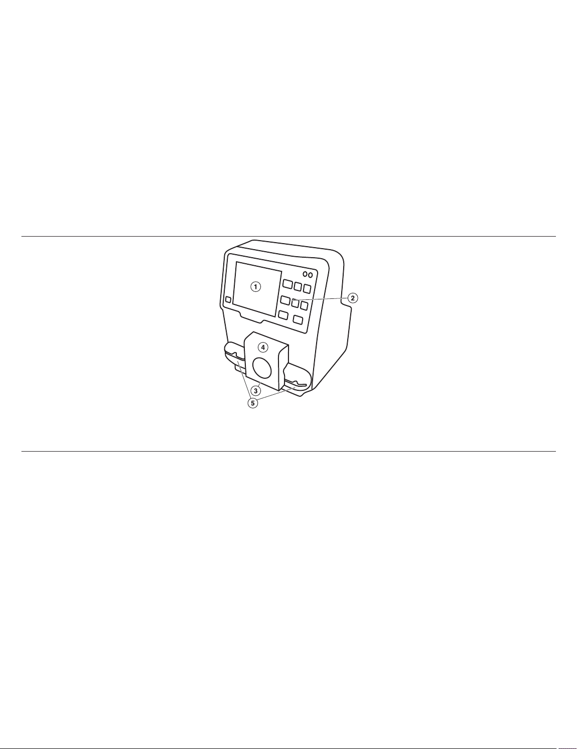
catheter. The DiamondTemp irrigation pump (Figure 1) delivers saline (0.9%) with Heparin at 1 IU/mL to the catheter when used in
conjunction with the DiamondTemp tubing set. The irrigation pump has a touch-screen display and flow control button that controls
a two-flow-rate feature for easy selection of the appropriate irrigation flow rate. The rate can be changed between a low flow rate
(1-5 mL/min) and a high flow rate (6-30 mL/min). Large numbers on the touch-screen display and an LED light on the flow control
button indicate the flow rate selected. The irrigation pump communicates with the DiamondTemp generator and may be operated
independently or under control of the generator.
Figure 1. DiamondTemp Irrigation Pump
1 Touch Screen Display
2 Flow-Rate Control Buttons
3 Pump Head
A transparent pump head door protects the rotating pump head, while allowing visibility of the entire tubing set during pump operation.
The tubing set is placed in the path and around the pump head for operation. The irrigation pump uses twin ultrasonic air bubble
sensors for added safety in detecting air infusion.
Audible or visual indicators and informational messages displayed on the touch-screen display warn of air in the tubing, an open pump
head door, or other operational conditions.
4 Pump Head Door
5 Air Bubble Sensors
2 Contents of package
The DiamondTemp irrigation pump is supplied nonsterile and is not intended for sterilization. The package contains the following
items:
• One model CEDTP100 irrigation pump
• One power cord
• One Ethernet cable (to connect the pump to the generator)
• Product documentation
3 Indications for use
The DiamondTemp irrigation pump is designed for use with the DiamondTemp ablation system. Refer to the DiamondTemp catheter
instructions for the indications for use. Carefully review the specific indications, contraindications, warnings, precautions, and adverse
events included with the DiamondTemp catheter before using the irrigation pump.
4
Page 5

4 Contraindications
The contraindications listed in the DiamondTemp catheter instructions apply to the use of the DiamondTemp irrigation pump. Carefully
review the specific indications, contraindications, warnings, precautions, and adverse events included with the DiamondTemp
catheter before using the irrigation pump.
5 Warnings and precautions
• Carefully read all DiamondTemp ablation system (catheter, generator, catheter-to-RFG cable, GenConnect cable, Generator
Connection Box E, EGM cable, irrigation pump, tubing set, and optional foot switch) instructions before use. Observe all
contraindications, warnings, and precautions noted in the directions. Failure to do so may result in patient complications. Review
any applicable product information with the patient, including known risks and contraindications.
• The irrigation pump is designed for use only with the DiamondTemp irrigation tubing set. Fluid extension lines should not be used
with the irrigation pump. Use of an inappropriate tubing set could cause conditions in the operation of the pump that may result
in improper irrigation or air induction into the patient.
• The DiamondTemp tubing set is specially designed to minimize the noise that may be induced on electrograms by the triboelectric
charge caused by the peristaltic motion of the irrigation pump head. The irrigation pump should not be used with any tubing other
than the DiamondTemp tubing set.
• The irrigation pump is designed for use only with sterile heparinized normal saline solution. Specified flowrate accuracy may not
be maintained when used with incompatible fluids or delivery devices.
• The irrigation pump is designed to terminate the flow of saline when certain operating conditions occur. Read all informational
messages carefully. Some steps require user action before continuing the procedure.
• It is the responsibility of hospital personnel to monitor and track the total saline load delivered to the patient to prevent overinfusion
of saline to the patient.
• To avoid the risk of electric shock, the irrigation pump must only be connected to a supply mains with protective earth ground.
• The irrigation pump should be placed on a hard, level surface and not be stacked on other equipment.
• Do not mount the irrigation pump on an IV pole.
• The air bubble detector is disabled during irrigation pump priming and purging functions. Do not prime or purge the catheter when
it is inserted in the vasculature of the patient.
• Do not remove the irrigation tubing set from the irrigation pump while the tubing set is in line with a catheter that is inside the patient.
• The DiamondTemp ablation system has not been evaluated for safety and compatibility in the magnetic resonance (MR)
environment. The safety of the DiamondTemp ablation system in the MR environment is unknown (such as any heating, migration,
or image artifacts). Scanning a patient during the use of these devices may result in patient injury.
• Do not modify the irrigation pump or accessory components. Modifications may reduce system effectiveness and impact patient
health.
• Carefully load the tubing set into the pump head. Do not attempt to remove the electrostatic discharge (ESD) pink sleeve
positioned over the tubing set.
• The tubing set uses an ESD pink sleeve to reduce triboelectric-charge artifacts. The ESD pink sleeve is located on the outer
surface between the retention clips. This section of the tubing set must be seated smoothly under the pump head rollers, with no
bends, twists, or kinks.
• The irrigation pump should not be connected to other infusion systems.
• To avoid the risk of explosion, do not use the irrigation pump in the presence of flammable anesthetics or gases.
• To avoid the risk of electrical shock or fire, do not expose the irrigation pump to excessive moisture, especially when power is
connected.
• To avoid the risk of exceeding the allowable touch current to the patient, do not simultaneously touch the patient and the accessible
contacts of the pump-RFG communications connector. The connector is located on the irrigation pump’s rear panel.
• Moving parts such as the transparent pump head door, pump head clamps, and rotating pump head should be operated with care.
• Before use, inspect the irrigation pump and packaging to verify that no damage has occurred. Do not use damaged products.
• Do not immerse the irrigation pump in any liquid or expose the pump to steam autoclave or ethylene oxide (EtO) sterilization.
• Electromagnetic interference produced by the irrigation pump may adversely affect the performance of other equipment.
Excessive EMI may cause the irrigation pump to enter a Safe State with a low flow rate. The pump is suitable for use in all
establishments other than domestic and those directly connected to the public low-voltage power supply network that supplies
buildings used for domestic purposes.
Note: The emission characteristics of this equipment make it suitable for use in industrial areas and hospitals. It is not intended
for use in a residential environment where this equipment might not offer adequate protection to radiofrequency communication
services. Use in such environments might require mitigation measures, such as relocating or reorienting the equipment.
5
Page 6

• Use of this equipment adjacent to or stacked with other equipment should be avoided because it could result in improper
operation. If such use is necessary, this equipment and the other equipment should be observed to verify that they are operating
normally.
• Use of accessories, transducers, and cables other than those specified or provided by the manufacturer of this equipment could
result in increased electromagnetic emissions or decreased electromagnetic immunity of this equipment and result in improper
operation.
• Portable RF communications equipment (including peripherals such as antenna cables and external antennas) should be used
no closer than 30 cm (12 in) to any part of the DiamondTemp system, including cables specified by the manufacturer. Otherwise,
degradation of the performance of this equipment could result.
• If for any reason the irrigation pump loses communication with the generator, or if the saline flow stops (0 mL/min), the generator
displays an information message indicating that the condition should be corrected before any other steps are taken.
• During use of the irrigation pump, pay attention to all messages, error codes, warnings, indicators, and tones, and exercise caution
as needed.
• There is no special handling, including no special storage or transport conditions, required for this device. Standard storage
conditions are sufficient to safeguard the device. Store the device in the original packaging at room temperature in a dry place.
6 Potential adverse events
The potential adverse events that may be associated with ablation procedures can vary greatly in frequency and severity and may
necessitate additional medical intervention, including surgery. Carefully review the specific indications, contraindications, warnings,
precautions, and adverse events included with each DiamondTemp catheter before using the DiamondTemp irrigation pump.
7 Unpacking the irrigation pump
Remove the power cord, Ethernet cable, and irrigation pump from the shipping container and inspect the irrigation pump. If the
irrigation pump has been damaged during shipping, do not use and contact a Medtronic representative.
8 Setting up the irrigation pump
8.1 Electrical connections
The DiamondTemp irrigation pump is intended for use only with the DiamondTemp ablation system. The irrigation pump should be
connected to the generator using the supplied Ethernet cable. Consult the generator user manual for additional details.
The irrigation pump operates using line power of 100 to 240 V, 50 to 60 Hz. The irrigation pump is not battery-powered and cannot be
moved during use.
Caution: To avoid the risk of electric shock, the irrigation pump must be connected to a supply mains with protective earth ground.
8.2 Turning on the irrigation pump
Before operation, the irrigation pump must be placed on a stable surface. Complete the following steps to turn on the irrigation pump:
1. Ensure that the power cord is plugged into a power line of 100 to 240 V, 50 to 60 Hz. Connect the irrigation pump to a
hospital-grade grounded power outlet only.
2. The power switch is located on the back panel of the irrigation pump near the power cord inlet. Turn on the switch at the rear of
the irrigation pump. The Medtronic logo will appear on the front screen and the irrigation pump will perform a self-test.
3. Once the self-test has passed, a tone will sound, and the touch-screen display will indicate a flow rate of 0 mL/min.
4. The irrigation pump and generator must be used in communication mode. To establish this, plug the Ethernet cable into the inlet
on the rear panel of the irrigation pump and connect the other end to the inlet on the rear panel of the generator.
5. Once communication is established between the two devices, a communication icon will be displayed on the upper portion of
the irrigation pump touch-screen.
6
Page 7
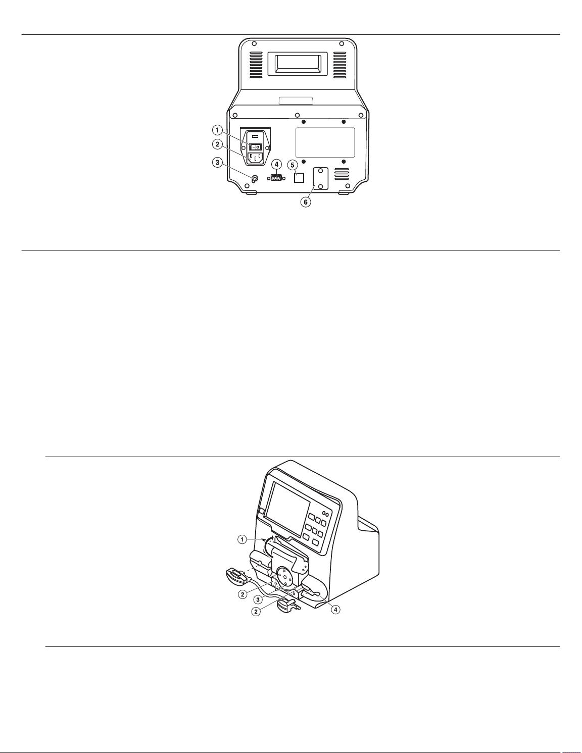
Figure 2. Rear Panel View of the Irrigation Pump
1 Power Switch
2 AC Power Cord Inlet
3 Equipotential Stud
4 Serial Port
5 Pump-Generator Communications Connector
6 USB Connection (maintenance)
8.3 Loading the tubing set in the irrigation pump
To load the tubing set in the irrigation pump, complete the following steps:
Caution: The DiamondTemp irrigation pump is intended for use only with the DiamondTemp tubing set.
1. Connect the 3-way stopcock (provided with the tubing set) to the patient end of the tubing set.
Cautions:
• A new tubing set must be used for every procedure.
• Do not reuse the tubing set.
2. Insert the drip chamber end of the tubing set into the heparinized normal saline solution bag. Hang the saline bag near the
irrigation pump and fill the drip chamber to approximately 2/3 full. Pass the patient end of the tubing set to the sterile field. While
in the sterile field, open the stopcock and fill the tubing set with irrigation fluid at the patient end of the tubing set. Remove any
trapped air and then close the 3-way stopcock. To ensure proper operation of the pump air bubble detectors, the outer surface
of the tubing set must be dry.
3. Open the transparent pump head door of the irrigation pump by lifting up from the bottom (Figure 3) to release the tubing set
guides and expose the tubing set path from the lower portion of the pump head.
Figure 3. Irrigation Pump with Pump Head Door Open
1 Transparent pump head door
2 Tubing guides
4. Note that the pump head rotates in a clockwise direction. Irrigation flow will enter the right-hand side of the pump and exit on the
left hand side of the pump head. The indicator arrows that are molded onto the proximal and distal tubing set retention clips align
with the direction of irrigation flow. Install the proximal tubing set retention clip (smaller of the two clips) into the tubing set retainer
on the right-hand side of the pump head by inserting it into the tubing set retainer with the molded indicator arrow facing outward
and in the direction of the pump flow path (Figure 4). Tactile feedback indicates when the tubing set retention clip is engaged
3 Tubing path around pump head
4 Tubing Set retainer
7
Page 8
correctly into the retainer. Press the retention clip firmly into its respective slot. Confirm that the red warning light, visible through
the clip, turns off after proper positioning.
5. Slide the pump head tubing set section under the pump head rollers into the tubing path, ensuring that the tubing set is grasped
by each of the tubing set guides (Figure 4). The tubing set has special features to reduce triboelectric-charge artifacts. An ESD
pink sleeve is placed over the tubing set, in between the retention clips.
Caution: Do not attempt to remove the pink ESD sleeve from the tubing set. Removing the sleeve may damage the tubing set
or render it non-functional.
This section of the tubing set must be seated smoothly under the pump head rollers, with no bends, twists, or kinks. Place the
tubing set snugly and smoothly over the two small metallic tubing set guides located to the right of the pump head rollers and
over the one small metallic tubing set guide to the left of the pump head rollers.
Figure 4. Insertion of Proximal Pump Retention Clip and Pump Head Tubing Set Section
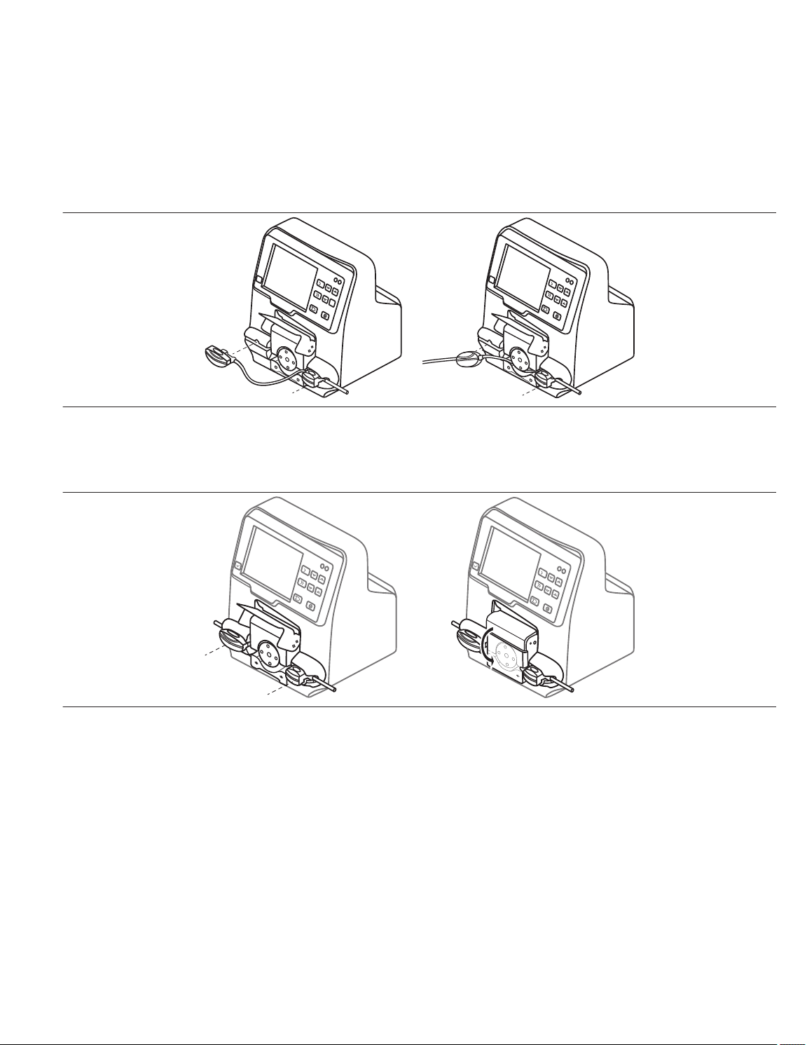
6. Gently stretch the tubing set and install the larger distal tubing set retention clip into the tubing set retainer on the left-hand side
of the pump head in the same manner as described in step 4 (Figure 5). Press the retention clip firmly into its respective slot.
Confirm that the red warning light, visible through the clip, turns off after proper positioning. Do not twist, bend, or kink the tubing
set.
Figure 5. Insertion of Tubing Set Distal Pump Retention Clip
7. Ensure that all tubing set elements are correctly placed in the tubing set path and both tubing set retention clips are securely
placed in the tubing set retainers. A red light will appear until clips are properly inserted.
8. Fully close the transparent pump head door of the irrigation pump (Figure 5). A message will appear at the bottom of the screen
if the clips are not properly inserted. The message will disappear when the clips are properly inserted. Ensure that the irrigation
pump touch-screen display does not show any messages. If the transparent pump head door of the irrigation pump is not closed
properly, a “pump cover open” message will appear on the information bar at the bottom of the touch-screen display.
Note: A message will not appear if the transparent pump head door is in the raised position when the irrigation pump is turned
on.
8.4 Preparing for irrigation
1. To prepare for irrigation, open the stopcock on the end of the tubing set, while continuing to maintain sterility on the patient end
of the tubing set.
2. Press and hold the purge button (Figure 6) on the irrigation pump to verify tubing set integrity. If air is visible in the tubing set or
if the pump displays an air bubble warning on the touch-screen display, press the purge button until the air is expelled through
the open end of the tubing set. The air bubble warning should clear after successfully purging the tubing set.
8
Page 9

3. Securely connect the tubing set through the 3-way stopcock to the female luer on the DiamondTemp catheter. Press the purge
flow button to fill the catheter with saline. Prepare the catheter as described in the DiamondTemp catheter instructions before
introducing it into the patient.
9 Working with the system controls
Note: The screen images shown are representative of what is seen on-screen with the software; actual images may differ slightly.
9.1 Touch-screen display and irrigation flow control panel
The irrigation flow control panel (Figure 6) and touch-screen display are located on the front of the irrigation pump and are used to set
and display the flow rate, to control the pump operation, to estimate the remaining available saline, and to display status messages.
The irrigation pump control panel consists of a touch-screen display, a message clearing button located to the left of the screen, and
a set of irrigation control buttons located to the right of the screen. The main screen displays real-time information on the rate of flow,
infused volume, and remaining volume. It also displays flow rate set-points for the low and high flow rate ranges and allows access to
the irrigation pump set-up menu. The control panel, touch screen, and use of the controls are detailed in Figure 6.
Figure 6. Irrigation Pump Front Panel
1 Communications Link Icon
2 Reset Remaining Fluid Button
3 Set Up/Screen Display
4 Message Clear Button
5 Message Field
6 Power Indicator
Set Point Adjust Buttons – Press the up or down arrow to increase or decrease the respective flow rate set point by 1 mL/min.
Set-points for non-active flows may be adjusted without changing the current flow rate.
Flow Rate Set Points – The current set-points for each flow rate are indicated to the right of the actual flow indicator.
Current Flow Rate – The current flow rate is indicated in large type in the center of the screen. It may be adjusted by using the set-point
adjust buttons for the currently selected set point.
Note: All of the previously listed controls may also be adjusted from the generator. Consult the generator user manual for more details.
Stop Flow Button – Press to stop rotation of the pump head. This will stop the flow of saline.
Purge Button – Press to purge the tubing set. When the button is held down, a flow of 60 mL/min is delivered and continues until the
button is released. Detection of air bubbles in the tubing set is disabled during this process. The purge button will not function unless
the irrigation pump has been stopped first.
Total Infused Volume – Press and hold down to view the estimated amount of fluid infused during the procedure.
Reset Remaining Fluid – Press and hold for 2 s when a new saline bag is started. This action resets the flow counter for each
individual bag.
Setup Screen/Display – Press to navigate to the setup screen.
Message Clear Button – Press to acknowledge and clear resolved messages.
Message Field – When a condition is detected, a message is displayed in this field until the condition is corrected and acknowledged
with the accept button. Once the condition is resolved and cleared, the irrigation pump will return to normal operation. This field also
displays status updates during the irrigation pump operation.
Communications Link Icon – The RFG icon will display when the link to the generator has been established.
7 Fault Indicator
8 Total Infused Fluid Button
9 Stop Flow Button
10 Purge Button
11 Set Point Adjust Buttons
9
Page 10

Flow Status – Indicates the current state of the irrigation pump (Off, Low, etc.).
Power Indicator – Light is displayed when power is applied.
Fault Indicator – Light is displayed when a hardware fault is encountered.
9.2 Set-up screen
The set-up screen (Figure 7) is used to select different operating parameters for the irrigation pump.
Figure 7. Irrigation Pump Touch-Screen Display
1 Saline Bag Size
2 High Flow ON Time Warning
3 Low Fluid Warning Level
4 Volume Control
Saline Bag Size – Choose the correct size of saline bag being used.
Low Fluid Warning Level – Press the up and down arrows to increase or decrease the fluid volume level at which the irrigation pump
will issue a warning indicating low saline volume remains. For this feature to work accurately, it is important to select the correct size
of the saline bag.
High Flow ON Time Warning – Press the up and down arrows to select when the irrigation pump will issue a warning that the pump
has been delivering fluid continuously at the high flow rate after the indicated time has passed.
Language – Press the up and down arrows to select a language for the device display.
Note: After a language is selected and the Back button is pressed to save the selection, restart the pump to display information in the
new language.
Remaining Fluid Display Units – Choose whether the remaining saline amount will be displayed in volume (mL) or time (min:s).
Volume Control – Press the up and down arrows to select the desired irrigation pump sound volume.
Back button – Press the back button to return to the main screen.
5 Language Button
6 Remaining Fluid Display Units
7 Back Button
10 Irrigation pump operation
After the irrigation pump has been turned on and appropriately set up (the tubing set is connected to the saline bag, loaded into the
pump and primed, and the patient end of the tubing set is connected to the DiamondTemp catheter), the system is ready for operation.
Refer to the instruction manuals for the DiamondTemp tubing set, DiamondTemp catheter, and the DiamondTemp generator. All
connections should be checked before introducing the catheter into the patient.
The irrigation pump must be operated in communication mode with the generator.
When communication mode is established between the irrigation pump and the generator via the Ethernet cable:
10
Page 11

• An icon with a checkmark and “RFG” appears in the upper-left corner of the pump display screen.
• The controls on the generator operate both devices.
• The controls on the irrigation pump do not change the output of the generator. However, the generator controls may adjust the flow
rate of the irrigation pump. The generator receives flow rate information from the irrigation pump and displays it accordingly.
• When the devices are connected, it is strongly recommended that the controls of the generator be used to operate both devices
for the duration of the procedure.
• The controls of the irrigation pump should be used only in the following cases:
– During setup
– During the initial purge of the tubing set
– During preparation of the catheter
– When an informational message needs to be addressed, acknowledged, or cleared
– When air is discovered in the tubing set
– In case of emergency
Operating the irrigation pump from the generator:
• The flow rate may be adjusted from the generator on the ablation screen on the main touch-screen display of the generator.
• Flow rate set-point for the low and high flow rate ranges can be adjusted on the main touch-screen display of the generator when
the generator is not delivering RF energy. Only the high flow rate can be adjusted on the generator during ablation.
• Flow rate set-point, pre-ablation ramps, and post-ablation ramps can be set in the Advanced Settings screen of the generator.
• To adjust the rate of flow from the Ablation screen, touch one of the flow adjustment buttons on the right side of the screen.
• For more details on the operation of the generator, reference the generator user manual.
When an ablation is initiated on the generator, irrigation flow from the irrigation pump will automatically be initiated at the “High” flow
rate set-point for the specified ramp time before delivery of RF energy. During the ablation, the irrigation pump will automatically deliver
irrigation flow at the “High” flow rate set-point. After termination of the ablation, the irrigation flow from the irrigation pump will
automatically continue at the “High” flow set-point for the specified post-cool period. After this time period, the irrigation pump will
automatically adjust the flow rate range to the range that was used before starting the ablation.
To adjust the preset rates of flow for the flow adjustment buttons, navigate to the Advanced Settings panel of the generator. Refer to
the generator user manual for additional details.
During ablation, the set rates of the low levels can only be changed using the irrigation pump controls.
Caution: Ensure the integrity of the irrigation pump and generator communication link throughout the duration of the procedure. If the
link becomes disconnected, check the connections between the devices and the link cable. The communications link will
automatically reestablish itself when the physical connections are corrected.
11 Indicators and informational codes
When certain conditions occur, the irrigation pump activates audible or visual indicators or displays informational messages. An
associated message will be displayed in the message field. For conditions such as an air bubble being detected, the pump flow will
be stopped, an audible indicator will be activated, and an informational message will be displayed.
To clear the message, press and hold the “Message Clear” (Figure 6) button to the left of the message field. Once the message has
been addressed and accepted, the pump will return to the normal operating mode. A list of indicators and messages, with appropriate
course of action, is provided in Table 1. Although codes P05 – P20 display an identical message on the pump screen, they provide
different troubleshooting information should the pump need repair work.
Table 1. Indicators/Informational Codes and Appropriate Action
Code Message & Actions
F-01 Low saline level. (F-01)
Please attach a new bag and reset the saline counter.
The warning will automatically clear.
F-02 Extended high flow use. (F-02)
Please avoid the use of high flow rates outside of ablation.
The warning will automatically clear.
F-93 OS Resource FAIL. (F-93)
Cycle the power on the irrigation pump.
If problem persists, contact Medtronic.
F-95 Internal pump failure. (F-95)
Cycle the power on the irrigation pump.
If problem persists, contact Medtronic.
11
Page 12

Table 1. Indicators/Informational Codes and Appropriate Action (continued)
Code Message & Actions
F-96 RPM Meas Mismatch. (F-96)
Cycle the power on the irrigation pump.
If problem persists, contact Medtronic.
F-97 Bubble Reading Mismatch. (F-97)
Cycle the power on the irrigation pump.
If problem persists, contact Medtronic.
F-98 Out of Heap Memory. (F-98)
Cycle the power on the irrigation pump.
If problem persists, contact Medtronic.
F-99 Software Logic Error. (F-99)
Cycle the power on the irrigation pump.
If problem persists, contact Medtronic.
P-01 Pump cover open. (P-01)
Pump cover was open when flow was off. Please close the transparent pump head cover.
The warning will automatically clear.
P-02 Close pump cover. (P-02)
Pump cover was open when flow was on. This represents a potential risk and needs acknowledgment
from user in order to clear the message. Please close the transparent pump head cover when flow is on.
Press the Message Clear button.
P-05 Internal pump failure. (P-05)
Cycle the power on the irrigation pump.
If problem persists, contact Medtronic.
P-06 Internal pump failure. (P-06)
Cycle the power on the irrigation pump.
If problem persists, contact Medtronic.
P-066 Internal pump failure. (P-066)
Cycle the power on the irrigation pump.
If problem persists, contact Medtronic.
P-07 Internal pump failure. (P-07)
Cycle the power on the irrigation pump.
If problem persists, contact Medtronic.
P-08 Internal pump failure. (P-08)
Cycle the power on the irrigation pump.
If problem persists, contact Medtronic.
P-09 Internal pump failure. (P-09)
Cycle the power on the irrigation pump.
If problem persists, contact Medtronic.
P-10 Internal pump failure. (P-10)
Cycle the power on the irrigation pump.
If problem persists, contact Medtronic.
P-11 Internal pump failure. (P-11)
Cycle the power on the irrigation pump.
If problem persists, contact Medtronic.
P-12 Internal pump failure. (P-12)
Cycle the power on the irrigation pump.
If problem persists, contact Medtronic.
P-13 Internal pump failure. (P-13)
Cycle the power on the irrigation pump.
If problem persists, contact Medtronic.
P-14 Internal pump failure. (P-14)
Cycle the power on the irrigation pump.
If problem persists, contact Medtronic.
P-15 Internal pump failure. (P-15)
Cycle the power on the irrigation pump.
If problem persists, contact Medtronic.
P-16 Internal pump failure. (P-16)
12
Page 13

Table 1. Indicators/Informational Codes and Appropriate Action (continued)
Code Message & Actions
Make sure no buttons are being depressed, and cycle the power on the irrigation pump.
If problem persists, contact Medtronic.
P-17 Internal pump failure. (P-17)
Make sure the touchscreen is not being touched, and cycle the power on the irrigation pump.
If problem persists, contact Medtronic.
P-18 Internal pump failure. (P-18)
Cycle the power on the irrigation pump.
If problem persists, contact Medtronic.
P-20 Internal pump failure. (P-20)
Cycle the power on the irrigation pump.
If problem persists, contact Medtronic.
P-21 Duplicate variable. (P-21)
Cycle the power on the irrigation pump.
If problem persists, contact Medtronic.
T-01 No tubing detected. (T-01)
Please insert a tubing set.
Press the Message Clear button.
T-02 Check Tubing insertion. (T-02)
Open the pump head cover, reseat the tubing set, and close the pump head cover.
Press the Message Clear button.
T-03 Air bubble detected! (T-03)
Please purge the tubing set of any bubbles.
Press the Message Clear button.
T-04 Occlusion detected! (T-04)
Please check the tubing set for occlusions. Replace tubing set if needed.
Press the Message Clear button.
T-05 No tubing detected. (T-05)
Please insert a tubing set.
Press the Message Clear button.
T-06 Tubing unseated. (T-06)
Open the pump head cover, reseat the tubing set, and close the pump head cover.
Press the Message Clear button.
13
Page 14

12 DiamondTemp ablation system architecture and cybersecurity
Figure 8. DiamondTemp Ablation System Architecture Diagram
1 Specially Configured Maintenance USB Thumb Drive
2 USB Port
3 Power Cable
4 RS-232 Output to EP Recording System
5 Static IP Output only Ethernet Port
6 RF Generator
7 Logged Measurements
8 Program & Settings
9 Pump Control port
The DiamondTemp generator and irrigation pump devices are not intended for use on or to be connected to a computer network and
do not accept wireless or unknown physical connections. A system architecture diagram for the DiamondTemp ablation system is
presented in Figure 8. The Pump Control port is dedicated only for communications between the DiamondTemp generator and
DiamondTemp irrigation pump. The USB port is used to export data when the system is not in use.
Any suspected compromise of the DiamondTemp ablation system’s cybersecurity, from such events as unauthorized access,
computer virus infection, or inadvertent connection to a network, should be reported to Medtronic. A proper course of action,
determined by Medtronic and the end user, should be determined before the system can be further used.
Software upgrades are to be performed only by Medtronic or authorized personnel.
The DiamondTemp ablation system contains the following commercial, open source, or off-the-shelf software:
• QT Third party graphics library
• ALSA Linux Sounds generation library
• SQLite Database Interface library
• Customized Linux Operating System including TCP/IP stack
10 CAT 5 Cable (Pump Flow Rate Commands &
Acknowledgements)
11 Irrigation Pump
12 Motor
13 Saline Bag
14 Irrigation Tubing
15 Patient
16 Catheter
13 Maintenance and service
13.1 Cleaning
The irrigation pump exterior surface may be cleaned with nonflammable and nonexplosive agents according to the following steps.
Follow recommended hospital procedures for cleaning and universal precautions for protective apparel when handling and cleaning
contaminated instruments. Make sure no fluids or moisture enter the interior of the irrigation pump during cleaning.
1. Before cleaning, turn off the irrigation pump and all its connections. Disconnect the power cord from the electrical power source
and from the rear of the generator.
2. Disconnect all other cables and peripherals.
3. Wipe the irrigation pump enclosure with a clean, soft nonlinting cloth dampened with a pH neutral detergent.
4. Wipe again with distilled or sterilized water.
14
Page 15

5. Wipe dry with a clean, soft, nonlinting cloth.
Note: Alternative cleaning solutions include Glutaraldehyde 2.4%, 70% IPA, sodium hypochlorite (0.1%), or equivalent. Follow
the manufacturer’s instructions for use.
6. Do not immerse the irrigation pump in any liquid or expose the irrigation pump to steam autoclave or ethylene oxide (EtO)
sterilization.
7. Do not expose the irrigation pump to excessive moisture, especially when the power is connected.
13.2 Maintenance
All servicing activities for the irrigation pump, except flow rate verification (see Section 13.3) and fuse replacement (see Section 13.4),
are performed only by the manufacturer. It is recommended that pump flow verification be performed every 12 months. Contact a
Medtronic representative for details.
Improper operation may cause damage to the irrigation pump. The irrigation pump may be damaged if altered by unauthorized
personnel. Contact a Medtronic representative for service or if you suspect an issue with the irrigation pump.
13.3 Irrigation pump flow rate verification
This section provides the information needed to verify the flow rate of the DiamondTemp irrigation pump. It is recommended that
verification of the pump flow rate be performed every 12 months. Only qualified personnel should complete flow verification. The user
facility is responsible for qualifying their personnel according to their local standards.
13.3.1 Required materials
The following materials are required for irrigation pump flow verification. Only the irrigation pump and tubing set are provided by the
manufacturer. It is expected that the other materials are available onsite.
• DiamondTemp irrigation pump
• DiamondTemp tubing set
• Digital timer
• Digital weight scale, 0.1 g resolution
• Fluid container
• 0.9 % saline
13.3.2 Procedure
Perform the following steps to verify the irrigation pump flow rate:
Note: Do not perform this procedure with the catheter or RFG connected.
1. Insert the tubing set into the pump.
Note: Do not connect the drip chamber to the saline until the tubing set is loaded in the pump.
2. Connect the drip chamber of the tubing set to the saline and press the Purge button until the tubing set is filled with saline and
there are no bubbles in the line.
3. Use the following fluid collection technique for all measurements.
Note: During the test, keep the saline away from the pump to avoid spills getting into the pump.
a. Place a fluid container on the scale. Either empty the container or ensure that it has enough capacity remaining for the fluid
volume to be collected. Ensure that the scale is reading weight in grams (not ounces). Zero the scale reading so that the
scale shows 0 g before the start of fluid collection.
b. Start the pump at the desired flow rate and allow it to run for a minimum of 30 s before starting a fluid collection.
c. Start collecting fluid by directing the fluid flow from the distal end of the tubing set into the fluid container.
d. While the pump is still running, stop collecting fluid by directing the flow away from the container after the required amount
of time is reached.
Note: Do not stop the flow on the pump.
4. Set the pump to deliver 3 mL/min. After 30 s, direct flow into the fluid container on the scale.
5. After 2 min ± 1 s, redirect flow away from the fluid container on the scale. Record the weight reading to at least one place to the
right of the decimal point (0.1 g).
6. Verify that the weight is between 5.1 g and 6.9 g.
7. Set the pump to deliver 30 mL/min. After 30 s, direct flow into the fluid container on the scale.
8. After 2 min ± 1 s, redirect flow away from the fluid container on the scale. Record the weight reading to at least one place to the
right of the decimal point (0.1 g).
9. Verify that the weight is between 56 g and 64 g.
15
Page 16

10. Run the pump on Purge for 30 s and then direct flow into the fluid container on the scale. After 60 s ± 1 s, redirect flow away from
the fluid container on the scale. Record the weight reading to at least one place to the right of the decimal point (0.1 g).
11. Verify that the weight is between 51 g and 69 g.
12. The verification is complete. If the verification did not pass, contact your Medtronic representative.
Table 2. Flow rate range
Flow Rate Acceptable range
3 mL/min 5.1 - 6.9 g
30 mL/min 56 - 64 g
Purge 51 - 69 g
13.4 Replacing fuses
To replace a fuse in the pump:
1. Remove the power cord.
2. Use a small blade screwdriver or similar tool to unlatch the
fuse holder door at the top of the fuse holder.
3. Use a small blade screwdriver or similar tool to remove the
red fuse block from the fuse holder.
4. Remove the defective fuse(s) and replace with the correct
size, rating, and type (replace with Littelfuse 218001.P or
equivalent). To avoid the risk of fire, use only the specified
fuse.
5. Reinstall the fuse block, close the fuse holder door, and
reinstall the power cord.
6. Switch on the pump and confirm it powers up.
14 Storage
Ensure that the irrigation pump transparent pump head door is closed when not in use.
Disconnect power prior to long-term storage. Store the device in the original packaging at room temperature in a dry place. For
information on operating environmental parameters, see Chapter 18.
15 Disposal
Refer to local requirements regarding the disposal of the irrigation pump and accessories.
16 Guidance and manufacturer’s declarations
Table 3. Guidance and manufacturer’s declaration – electromagnetic emissions
The irrigation pump is intended for use in the electromagnetic environment specified below. The customer or the user of the irrigation
pump should ensure that it is used in such an environment.
Emissions test Compli-
ance
RF emissions
CISPR11
RF emissions
CISPR11
Harmonic emissions
IEC 61000-3-2
Voltage fluctuations/flicker emissions
IEC 61000-3-3
Group 1 The irrigation pump may emit electromagnetic energy in
Class A The irrigation pump is suitable for use in all establish-
Class A
Complies
Electromagnetic environment—guidance
order to perform its intended function. Nearby electronic
equipment may be affected.
ments other than domestic and those directly connected
to the public low-voltage power supply network that supplies buildings used for domestic purposes.
16
Page 17

Table 4. Guidance and manufacturer’s declaration – electromagnetic immunity
The irrigation pump is intended for use in the electromagnetic environment specified below. The customer or the user of the irrigation
pump should ensure that it is used in such an environment.
Immunity test IEC 60601 Test level Compliance level Electromagnetic environment—guidance
Electrostatic discharge
(ESD)
IEC 61000-4-2 ±2 kV, ±4 kV, ±8 kV,
Electrical fast transient/burst
IEC 61000-4-4 ±2 kV @ 100 kHz repeti-
±8 kV contact ±8 kV contact Floors should be wood, concrete, or ceramic tile. If
floors are covered with synthetic material, the relative humidity should be at least 30%.
Mains power quality should be that of a typical commercial or hospital environment.
±15 kV air
±2 kV @ 100 kHz repeti-
tion frequency for power
supply lines
±2 kV, ±4 kV, ±8 kV,
±15 kV air
±2 kV @ 100 kHz repetition frequency for power
supply lines
±2 kV @ 100 kHz repetition frequency for
input/output lines
tion frequency for
input/output lines
Surge Power inputs: Power inputs: Mains power quality should be that of a typical com-
±0.5 kV, ±1 kV Line-toLine
IEC 61000-4-5 ±0.5 kV, ±1 kV, ±2 kV
Line-to-Ground
±0.5 kV, ±1 kV Line-to-
Line
±0.5 kV, ±1 kV, ±2 kV
Line-to-Ground
mercial or hospital environment.
Signal input/outputs: Signal input/outputs:
±2 kV Line-to-Ground ±2 kV Line-to-Ground
Voltage dips, short interruptions and voltage variations on power supply
input lines
IEC 61000-4-11 0% UT; 1 cycle and 70%
Voltage dips: Voltage dips: Mains power quality should be that of a typical com0% UT; 0.5 cycle 0% UT; 0.5 cycle
At 0°, 45°, 90°, 135°,
180°, 225°, 270° and
315° phase angles
At 0°, 45°, 90°, 135°,
180°, 225°, 270° and
315° phase angles
0% UT;1 cycle and 70%
UT; 25/30 cycles
UT; 25/30 cycles
mercial or hospital environment.
If the user of the irrigation pump requires continued
operation during power mains interruptions, it is
recommended that the irrigation pump be powered
from an uninterruptible power supply or battery.
Single phase: at 0° Single phase: at 0°
Voltage interruptions: Voltage interruptions:
0% UT; 250/300 cycle 0% UT; 250/300 cycle
Note: UT is the a.c. mains voltage before application of the test level.
Power frequency
(50/60 Hz) magnetic
field
30 A/m 30 A/m Power frequency magnetic fields should be at levels
characteristic of a typical location in a typical com-
mercial or hospital environment.
IEC 61000-4-8 50 Hz or 60 Hz 50 Hz or 60 Hz
Conducted RF 0.15 MHz – 80 MHz 3 V,
80 % AM at 1 kHz
IEC 61000-4-6 ISM bands between
0.15 MHz and 80 MHz
6 V, 80 % AM at 1 kHz
Radiated RF EM fields
Band (MHz) Wireless Service Immunity Test Level
including proximity fields
0.15 MHz – 80 MHz 3 V,
80 % AM at 1 kHz
ISM bands between
0.15 MHz and 80 MHz
6 V, 80 % AM at 1 kHz
Mains power quality should be that of a typical com-
mercial or hospital environment.
Compliance Test Level
(V/m)
(V/m)
17
Page 18

Table 4. Guidance and manufacturer’s declaration – electromagnetic immunity (continued)
from RF wireless com-
munications equipment
IEC 61000-4-3
150 kHz – 80 MHz General < 3 < 3
80 MHz – 2.7 GHz General 3 3
380 – 390 TETRA 400 27 27
430 – 470 GMRS 460, FRS 460 28 28
704 – 787 LTE Band 13, 1 9 9
800 – 960 GSM 800/900,
28 28
TETRA 800, iDEN 820,
CDMA 850, LTE Band 5
1,700 – 1,990 GSM 1800; CDMA 1900;
28 28
GSM 1900; DECT; LTE
Band 1, 3, 4, 25; UMTS
2,400 – 2,570 Bluetooth, WLAN,
28 28
802.11 b/g/n,
RFID 2450, LTE Band 7
5,100 – 5,800 WLAN 802.11 a/n 9 9
Portable and mobile RF communications equipment should be used no closer to any part of the irrigation pump, including cables,
than the recommended separation distance calculated from the equation:
d=6/E×√P Where:
d is the separation in meters
P is the maximum output power rating of the transmitter in watts (W) according to the manufacturer
E is the Compliance Test Level indicated above.
Interference may occur in the vicinity of equipment marked with the following
symbol:
a
Field strengths from fixed transmitters, such as base stations for radio (cellular/cordless) telephones and land mobile radios,
amateur radio, AM and FM radio broadcast and TV broadcast cannot be predicted theoretically with accuracy. To assess the
electromagnetic environment due to fixed RF transmitters, an electromagnetic site survey should be considered. If the measured
field strength in the location in which the irrigation pump or any of its components are used exceeds the applicable RF compliance
level above, the irrigation pump should be observed to verify normal operation. If abnormal performance is observed, additional
measures may be necessary, such as reorienting or relocating components or the irrigation pump.
b
Within the frequency range 150 kHz to 80 MHz, field strengths should be less than 3 V/m.
Table 5. Recommended separation distances between portable and mobile RF communications equipment and the Irrigation Pump
The irrigation pump is intended for use in an electromagnetic environment in which radiated RF disturbances are controlled. The
customer or the user of the irrigation pump can help prevent electromagnetic interference by maintaining a minimum distance
between portable and mobile RF communications equipment (transmitters) and the irrigation pump as recommended below,
according to the maximum output power of the communications equipment.
Rated maximum output power
of transmitter
(W)
150 kHz to 80 MHz
d = 1.2√P
Separation distance according to frequency of transmitter
(m)
80 MHz to 800 MHz
800 MHz to 2.5 GHz
d = 1.2√P
d = 2.3√P
0.01 0.12 0.12 0.23
0.1 0.38 0.38 0.73
1 1.2 1.2 2.3
10 3.8 3.8 7.3
100 12 12 23
For transmitters rated at a maximum output power not listed above, the recommended separation distance (d) in meters (m) can be
determined using the equation applicable to the frequency of the transmitter, where P is the maximum output power rating of the
transmitter in watts (W) according to the transmitter manufacturer.
Note 1 – At 80 MHz and 800 MHz, the separation distance for the higher frequency range applies.
Note 2 – These guidelines may not apply in all situations. Electromagnetic propagation is affected by absorption and reflection from
structures, objects and people.
18
Page 19

17 Technical specifications
• According to IEC 60601-1, the irrigation pump is classified as a Class 1, Type CF ordinary equipment for continuous use.
• Applied Part Classification, Catheter – Type CF defibrillation proof.
• The irrigation pump complies with IEC 60601-1 and IEC 60601-1-2.
• AC Power: 100-240 VAC, 0.40-0.26 A, 50-60 Hz.
• To avoid the risk of electric shock, connect only to a grounded hospital outlet.
• To avoid the risk of fire, use two Littelfuse 218001.P fuses, or equivalent.
18 Environmental conditions
Note: Allow the system to equilibrate to room temperature for a minimum of 4 hours if the system has been stored at temperatures
outside of the operational temperature range.
Operational temperature: 15°C to 30°C (59°F to 86°F)
Operational humidity: 30% to 75% relative humidity (noncondensing)
Operational pressure: 70 to 106 kPa
Stacking height: Maximum of two shipping boxes on top of each other
Low flow rate range: 1 to 5 mL/min, 1 mL/min increment
High flow rate range: 6 to 30 mL/min, 1 mL/min increment
Purge flow rate: 60 mL/min. Note that air bubble detection is disabled during purging flow.
Maximum back pressure: 45 psi (310 kPa), max
Flow rate accuracy: 6 to 30 mL/min (±10%), 3 to 5 mL/min (±15%), 1 to 2 mL/min (±20%)
Weight: 6 kg or less
Moisture protection rating: The pump complies with the following international electrical safety rating with regard to
water, as required by IEC 60601-1:
IPX0, not water resistant
Flow rate, back pressure, and flow rate accuracy depend upon the use of compatible substances. The irrigation pump is only
compatible with 0.9% saline solution (pure or heparinized)
Minimum detectable air bubble size: 2 µL
Dimensions: 26 cm x 27 cm x 31 cm (L x W x H)
19 Limited warranty
The following limited warranty applies to customers within the United States only:
A. This limited warranty provides the following assurance to the customer of the Medtronic DiamondTemp RF generator, irrigation
pump, and GenConnect cable, with reusable parts (foot switch, ethernet cable, and power cord), hereafter collectively referred to as
the DiamondTemp ablation system. Subject to the limitations herein, Medtronic warrants the DiamondTemp ablation system sold to
the customer will be free from defects in materials and workmanship under normal usage for a period of 12 months from the delivery
date at the customer’s facility.
B. Should the DiamondTemp ablation system fail to meet the above warranty, Medtronic will at its option, repair or replace such
DiamondTemp ablation system, or any portion thereof. For the limited warranty to apply, the following conditions must be met:(1)
Medtronic must be notified of and confirm the failure of the alleged defect within 60 days after discovery of the defect.
(2) The DiamondTemp ablation system must not have been repaired or altered outside of authorized personnel at Medtronic.
(3) THE DIAMONDTEMP ABLATION SYSTEM MUST BE USED IN ACCORDANCE WITH LABELING AND NOT ALTERED OR
SUBJECTED TO MISUSE, ABUSE, IMPROPER HANDLING, OR ACCIDENT, INCLUDING, BUT NOT LIMITED TO, FIRE, FLOOD
OR NATURAL DISASTERS.
C. At the discretion of Medtronic, parts or assemblies used or installed as part of the DiamondTemp ablation system may be either new
or rebuilt of equal or improved quality. All parts removed or replaced during maintenance become the property of Medtronic.
D. This limited warranty is limited to its express terms. In particular:
(1) Except as expressly provided by this limited warranty, MEDTRONIC EXPRESSLY DISCLAIMS ANY REPRESENTATION OR
WARRANTY OF ANY KIND, EXPRESS OR IMPLIED, WHETHER AS TO MERCHANTABILITY, FITNESS FOR A PARTICULAR
PURPOSE, OR ANY OTHER MATTER. THE REMEDIES SET FORTH IN THIS WARRANTY ARE THE EXCLUSIVE REMEDIES
AVAILABLE TO THE CUSTOMER OR ANY THIRD PARTY FOR BREACH OF WARRANTY. MEDTRONIC SHALL HAVE NO
LIABILITY TO ANY PERSON FOR INCIDENTAL, CONSEQUENTIAL, OR PUNITIVE DAMAGES OF ANY DESCRIPTION,
WHETHER ARISING OUT OF WARRANTY, OTHER CONTRACT, TORT, OR OTHERWISE.
19
Page 20

(2) Except as expressly provided by this limited warranty, MEDTRONIC IS NOT RESPONSIBLE FOR ANY DIRECT, INDIRECT,
INCIDENTAL, OR CONSEQUENTIAL DAMAGES BASED ON ANY DEFECT, MALFUNCTION, OR FAILURE OF THE DEVICE TO
FUNCTION WITHIN NORMAL TOLERANCE, WHETHER THE CLAIM IS BASED ON WARRANTY, CONTRACT, TORT, OR
OTHERWISE.
E. The exclusions and limitations set out above are not intended to, and should not be construed so as to contravene mandatory
provisions of applicable law. If any part or term of this limited warranty is held to be illegal, unenforceable, or in conflict with applicable
law by a court of competent jurisdiction, the validity of the remaining portions of the limited warranty shall not be affected, and all rights
and obligations shall be construed and enforced as if this limited warranty did not contain the particular part or term held to be invalid.
This limited warranty gives the customer specific legal rights. The customer may also have other rights that vary from state to state.
F. No person has any authority to bind Medtronic to any representation, condition, or warranty except this limited warranty.
G. This limited warranty is not applicable to accessories or products used with the DiamondTemp ablation system unless specifically
noted.
20 Glossary of symbols
The following table defines symbols that are used on packaging and product labeling. Refer to the labels to determine which symbols
apply to this product and for the product-specific information, such as the date of manufacture, manufactured-in location, and use-by
date.
Symbol
Standard/Standard title or
reference
21 CFR 801.109
a
Symbol title/Reference number Explanatory text
Prescription only USA Federal law restricts this
device to sale by or on the order
of a licensed healthcare practitioner.
ISO 15223-1
d
Consult instructions for use
(clause 5.4.3)
Consult instructions for use at
this website:
www.medtronic.com/manuals
EN 50419
IEC 60601-1
ISO 15223-1
b
c
d
Recycle: Electronic Equipment Do NOT throw in trash.
Follow instructions for use
(Table D2, Symbol 10)
Catalog number
(clause 5.1.6)
Refer to instruction manual/booklet (blue symbol).
Indicates the manufacturer’s
catalog number so the device
can be identified
ISO 15223-1
d
Serial number
(clause 5.1.7)
Indicates the manufacturer’s
serial number so that the device
can be identified
ISO 15223-1
N/A Manufactured in/ manufactur-
ISO 15223-1
d
Manufacturer
(clause 5.1.1)
Indicates the medical device
manufacturer
Indicates where the device was
d
Date of manufacture
(clause 5.1.3)
ing site
manufactured
Indicates the date when the
medical device was manufactured
ISO 15223-1
d
Keep dry
(clause 5.3.4)
Indicates a medical device that
needs to be protected from
moisture
ISO 15223-1
d
Do not use if package is damaged
(clause 5.2.8)
Indicates a medical device that
should not be used if the package has been damaged or
opened.
ISO 15223-1
d
Temperature limit
(clause 5.3.7)
Indicates the temperature limits
to which the medical device can
be safely exposed
N/A Storage temperature limit Indicates the required temper-
ature range for storing the
device
20
Page 21

Symbol
Standard/Standard title or
reference
Symbol title/Reference number Explanatory text
N/A Transit temperature limit Indicates the required temper-
ature range for transporting the
device
ISO 15223-1
d
Humidity limitation
(clause 5.3.8)
Indicates the range of humidity
to which the medical device can
be safely exposed
ISO 15223-1
d
Atmospheric pressure limitation
(clause 5.3.9)
Indicates the range of atmospheric pressure to which the
medical device can be safely
exposed
ISO 7000
e
Stacking limit by number
(symbol 2403)
To indicate that items shall not
be vertically stacked beyond
the specified number
IEC 60529
f
International Protection (IP)
Code
Indicates the product is not
water resistant
N/A Package contents Indicates the components
included in the device package
N/A Irrigation pump Indicates that the type of device
is an irrigation pump
N/A Accessories Indicates that accessories are
included in the device package
ISO 7000
e
Product documentation
(symbol 0419)
Indicates that product documentation is included in the
device package
N/A RFG connection Indicates a generator connec-
tion
ISO 7000
e
Equipotentiality
(symbol 5021)
To identify the terminals which,
when connected together, bring
the various parts of an equipment or of a system to the same
potential, not necessarily being
the earth (ground) potential,
e.g. for local bonding.
ISO 7000
e
Alternating current
Alternating current
(symbol 5032)
ISO 7000
ISO 7000
ISO 7000
e
e
e
Defibrillation Proof Type CF
Applied Part
(symbol 5336)
Stand by
(symbol 5009)
OFF
To identify a defibrillation-proof
type CF applied part complying
with IEC 60601-1.
Power in Standby (lit amber) or
ON (lit green)
Power OFF
(symbol 5008)
ISO 7000
e
ON
Power ON
(symbol 5007)
N/A N/A Fuses
N/A N/A EGM Output – Filtered ECG
Pace
N/A N/A Video Output
N/A N/A Serial Output
N/A N/A USB port
N/A N/A Catheter connection
21
Page 22

Symbol
Standard/Standard title or
reference
Symbol title/Reference number Explanatory text
N/A N/A Indicates the device Stop but-
ton (red symbol)
N/A N/A Indicates the device Start but-
ton (green symbol)
N/A Compliance mark Indicates conformance to appli-
cable standards
a
21 CFR 801.109: United States Code of Federal Regulations, Title 21, Food and Drugs
b
EN 50419: Marking of electrical and electronic equipment in accordance with Article 11(2) of Directive 2002/96/EC (WEEE)
c
IEC 60601-1: Medical electrical equipment – Part 1: General requirements for basic safety and essential performance
d
ISO 15223-1: Medical devices – Symbols to be used with medical device labels, labeling and information to be supplied
e
ISO 7000: Graphical symbols for use on equipment
f
IEC 60529: Degrees of protection provided by enclosures (IP Code)
22
Page 23

Page 24

Medtronic, Inc.
*M005670C001*
710 Medtronic Parkway
Minneapolis, MN 55432
USA
www.medtronic.com
© 2022 Medtronic
M005670C001 B
2022-01-27
 Loading...