

Page 1

O-arm™ O2 Imaging System
BI-700-02000
User
Manual (USA Version)
Read this manual completely before using this device.
Page 2

Copyright © Medtronic Navigation, Inc. All rights reserved.
Document Title: O-arm™ O2 Imaging System User Manual (USA Version)
Document Number: BI-500-01119 Rev. 01
No part of this documentation may be reproduced in any form or by any means or used to make any
derivative work (such as translation, transformation, or adaptation) without written permission from
Medtronic Navigation, Inc.
The information contained in this document is accurate at time of publication. Medtronic Navigation,
Inc. reserves the right to revise this documentation and to make any changes in content from time
to time without obligation on the part of Medtronic Navigation, Inc. to provide notification of such
revision or change.
Medtronic Navigation, Inc. provides this documentation without warranty, term, or condition of any
kind, either implied or expressed, including, but not limited to, the implied warranties, terms or
conditions of merchantability, satisfactory quality, and fitness for a particular purpose. Medtronic
Navigation, Inc. may make improvements or changes in the product(s) and/or the program(s)
described in this documentation at any time.
O-arm, Isowag, and StealthStation S7 and S8 are trademarks of Medtronic Navigation, Inc. All other
product or service names are the property of their respective owners.
Revision Release date Application
01 2020-05 Describes the operation of the O-arm™ O2 Imaging System with
software version 4.2.x. If you have a later version of software, please
check the release notes to determine if this manual is still current for
your version.
2
Page 3

Contents
1.General Information and Safety
Indications for Use, Compliance, and Patient Environment ...............................9
Indications for Use and Responsibilities......................................................... 9
Patient Environment .....................................................................................12
Safety ...............................................................................................................14
Overview ...................................................................................................... 14
Personnel Safety ..........................................................................................14
Radiation Safety ...........................................................................................21
Use of Images in Image-Guided Treatments ............................................... 22
Imaging Patients With Electronic Medical Devices ......................................22
Electromagnetic Compatibility ......................................................................23
Electrical Safety............................................................................................ 24
Mechanical Safety ........................................................................................26
General Use Safety ......................................................................................28
Emergency Procedures................................................................................29
2.System Overview
Introduction to the System ...............................................................................33
Overview ...................................................................................................... 33
The Image Acquisition System (IAS)............................................................ 34
The Mobile View Station (MVS) ................................................................... 35
Acquisition Modes ........................................................................................ 38
2D Modes ..................................................................................................... 38
2D Long Film Mode (Optional) ..................................................................... 39
3D Modes ..................................................................................................... 39
Optional 3D Features ................................................................................... 40
X-ray Options ...............................................................................................41
Patient Exam Data Capabilities .................................................................... 41
3.Controls and Indicators
IAS Controls and Indicators ............................................................................. 45
Control Locations .........................................................................................45
IAS Connector Panel.................................................................................... 46
The IAS Power Control Panel ...................................................................... 47
The Pendant................................................................................................. 50
Handswitch and Footswitch .........................................................................53
MVS Components ............................................................................................55
The Mobile View Station............................................................................... 55
The Monitor .................................................................................................. 57
The Keyboard and Wireless Mouse .............................................................58
Locking Casters............................................................................................ 61
4.Powering Up and Configuring the System
Connecting and Powering Up the System .......................................................63
Cable Connections .......................................................................................63
Log in Security with User Authentication ......................................................67
Changing User Authentication Settings........................................................ 69
3
Page 4

Configuring the System with the Technical Service Console ...........................73
Configuration Overview ................................................................................73
Configuring Interface Language and Units ...................................................75
Setting Up DICOM Export Configurations ........................................................78
Connecting to the Network ...........................................................................78
Configuring a Worklist Server .......................................................................79
Connecting and Configuring an Image Guided Surgery (IGS) System .......82
Selecting an IGS, StealthStation™ System, or Navigation Server from a
Shared Network ............................................................................................85
Configuring the DICOM Store Server ...........................................................87
Adding To and Modifying the Physicians List ...............................................88
Optimizing the Monitor Display .....................................................................90
5.Setup in the Operating Room
Moving the System ...........................................................................................93
Moving the IAS .............................................................................................93
Moving the MVS ...........................................................................................94
Powering Up the System ..................................................................................94
Connecting the IAS and MVS and Powering Up the System .......................94
Unpacking and Activating the Mouse ...........................................................96
Entering Patient Information .........................................................................98
Entering New Patient Data at Time of Examination......................................99
Entering Patient Data on the Scheduled Exams Page ...............................101
Acquiring Patient Information from Outside Sources..................................104
Outside Sources of Patient Information ..........................................................104
Applying a Sterile Drape to the IAS Gantry ....................................................106
Overview.....................................................................................................106
The Tube Drape .........................................................................................107
The Bar Drape ............................................................................................113
6.Positioning the Gantry
Introduction to Imaging ...................................................................................115
Imaging Overview .......................................................................................115
Using the Door and Preparing the Gantry ......................................................115
Work Flow Recommendations for Using the O-arm™ Door........................115
Positioning the Gantry ...............................................................................116
Viewing X-Ray Tube Icon and Gantry Tilt Icon on Pendant .......................123
Positioning the Gantry for Imaging .............................................................123
Pendant Buttons for Gantry Movement and Beam Positioning ..................126
Gantry Movements .....................................................................................128
The Gantry Docked Position.......................................................................129
Gantry Door Open/Close Positions.............................................................130
Gantry Tilt Control.......................................................................................130
Gantry Up and Down Control......................................................................132
Gantry Isowag™ Control (Optional).............................................................133
Gantry Wag Control ....................................................................................134
Gantry Transverse (In/Out) Control ............................................................136
Gantry Longitudinal (Left/Right) Control .....................................................137
4
Page 5

7.Imaging
Aligning the X-ray Beam Path ....................................................................138
The Laser Alignment Lights........................................................................140
Moving the Gantry Out of the Way .................................................................143
Positioning the Gantry Out of the Way for Surgery .................................... 143
Moving the IAS Laterally ............................................................................ 144
Moving the IAS Away from the Operating Table ........................................145
Imaging Modes ..............................................................................................149
Overview .................................................................................................... 149
Image Control Buttons................................................................................ 150
Image Storage Capacity............................................................................. 151
Using the 2D Mode ........................................................................................153
Overview .................................................................................................... 153
Acquiring 2D Images ..................................................................................155
Optimizing 2D Image Quality Using the Softkeys....................................... 157
Manipulating Image Display in the 2D Mode..............................................159
Viewing a Region of Interest (ROI)............................................................. 161
Storing Positions and Acquisition Settings ................................................. 163
Using the Multi-plane 2D Mode ......................................................................165
Overview .................................................................................................... 165
M-2D Image Acquisition .............................................................................165
Manipulating Image Display in the M-2D Mode.......................................... 166
Using 2D Long Film Mode (Optional) .............................................................168
Overview .................................................................................................... 168
Summary of Steps for Acquiring 2D Long Film Scans .............................. 169
Acquiring 2D Long Film Scans ................................................................... 170
Resolving gantry position errors for 2D Long Film scans ........................... 175
Adjusting the Plane of Focus Manually on 2D Long Film Image ................ 177
Manipulating Image Display in 2D Long Film Mode ...................................178
Using 3D Modes ............................................................................................179
Overview .................................................................................................... 179
3D Image Acquisition ..................................................................................... 182
Gantry Position...........................................................................................182
Image-Guided Surgery ...............................................................................182
Selecting and Activating 3D Modes............................................................ 182
Using Saline Solution ................................................................................. 182
Pausing Respiration ...................................................................................183
Using Preset Collimation Settings ..............................................................183
Selecting Acquisition Settings .................................................................... 183
Guidance for Imaging Pediatric or Small Patients......................................187
Pendant Buttons and Indicators for X-rays................................................. 188
Acquiring 3D Stereotaxy Scans.................................................................. 188
Acquiring a 3D Scan...................................................................................190
Manipulating Image Display in the 3D Mode..............................................191
Advanced Imaging Features in 3D Mode ................................................... 194
Dose Reporting ..............................................................................................196
5
Page 6

Overview.....................................................................................................196
The Dose Report Header............................................................................196
Fluoroscopy Dose Section..........................................................................197
3D Dose Section.........................................................................................198
2D Long Film Dose Section ........................................................................198
Total Fluoroscopy Dose and 2D Long Film Dose Section..........................198
Viewing, Saving, and Exporting Dose Reports ...........................................199
Transferring Non-Navigated Images to a StealthStation™ System or Navigation
Server .............................................................................................................202
Method 1: Acquiring non-navigated scans by using the softkey on the pendant
202
Method 2: Choosing to acquire non-navigated scans from the MVS when pa-
tient tracker or O-arm™ tracker is not visible to camera .............................203
Locating Non-Navigated Images on the StealthStation™ System ..............204
8.Reviewing, Editing, and Annotating Patient Data
Reviewing Patient Data ..................................................................................207
Accessing and Reviewing Patient Exams...................................................207
Editing and Deleting Database Entries .......................................................212
Exporting Patient Studies and Images ...........................................................215
Export Options ............................................................................................215
Exporting Images to External Media...........................................................215
Exporting Images Across a Network ..............................................................216
Overview.....................................................................................................216
Exporting Images to a DICOM Store Server...............................................216
Exporting Images to an Image Guided Surgery (IGS) System...................217
Printing Images to a Local Printer...............................................................218
Image Annotation ...........................................................................................219
Overview.....................................................................................................219
Viewing Annotations ...................................................................................220
Launching the Annotation Editor.................................................................220
Using the Annotation Editor Toolbar ..............................................................221
Imaging Magnification ................................................................................222
Selecting Elements .....................................................................................223
Moving Elements ........................................................................................223
Changing Element Layers .........................................................................223
Rotating Elements ......................................................................................224
Deleting Elements.......................................................................................224
Undoing All Changes .................................................................................224
Saving and Exiting Annotated Images ........................................................224
Adding Text, Line, and Angle Annotations ......................................................224
Adding Text and Orientation Markers to Images ........................................224
Adding Lines and Arrows to Images ...........................................................225
Adding Angle Measurements to Images.....................................................226
Image Stitching ...............................................................................................232
Overview.....................................................................................................232
Stitching Restrictions .................................................................................232
Stitching Overview ......................................................................................233
6
Page 7

Selecting Images to Stitch.......................................................................... 233
9.Maintenance and Troubleshooting
Powering Down and Storing the System ........................................................ 237
Powering Down .......................................................................................... 237
Cleaning ..................................................................................................... 238
Storing the System .....................................................................................240
Charging the Batteries................................................................................241
Performance Checks and Maintenance .........................................................242
Overview ........................................................................................................242
Frequency Guidelines ................................................................................242
Initial Setup................................................................................................. 243
Performance Checks.................................................................................. 243
Periodic Maintenance – Gain Calibrations .................................................245
Dose Calibration Records .......................................................................... 250
Additional Periodic Maintenance ................................................................ 250
Periodic Maintenance – Home Calibration ................................................. 250
Door Cable Inspection................................................................................ 251
Emergency Procedures .................................................................................254
Opening the IAS Gantry Door When the System is Unresponsive ............ 254
Unintended Emergency Shutdown (E-Stop) .............................................. 257
Moving the IAS When Battery Power Is Low..............................................257
Emergency Stop......................................................................................... 259
Troubleshooting.......................................................................................... 259
Audit Log Data ...............................................................................................262
Viewing and Exporting Audit Logs.............................................................. 263
10.Acronyms, Labels and Technical References
Acronyms .......................................................................................................265
Labels and Symbols .......................................................................................266
Specifications ............................................................................................. 274
Safety Classifications and Standards.........................................................287
Electromagnetic Compatibility ....................................................................290
Dose Evaluation Methods .......................................................................... 296
A.User QC Test Procedures
List of User QC Tests ..................................................................................... 299
Contacting Medtronic technical service ..........................................................299
List of test equipment .....................................................................................299
Checking General System Safety .................................................................. 300
Radiation safety.......................................................................................... 300
Electrical safety .......................................................................................... 301
Physical safety ...........................................................................................301
Testing the system startup functionality ..................................................... 301
Safety Inspections ..........................................................................................302
Testing the Emergency Stop......................................................................302
X-ray safety inspection ............................................................................... 303
Mechanical safety inspection ..................................................................... 306
Testing 2D Fluoroscopy Image Quality and Dose ..........................................309
7
Page 8

Measuring 2D fluoroscopy output ...............................................................309
Testing the 2D fluoroscopic output .............................................................311
Testing 2D Long Film Image Quality and Dose ..............................................323
Verifying the display of 2D Long Film Dose Area Product (DAP) ...............323
2D Long Film spatial and contrast resolution test .......................................326
Testing 3D Volumetric Image Quality and Dose .............................................331
3D Dose Accuracy ......................................................................................331
3D Image Quality ........................................................................................336
8
Page 9

1 General Information and Safety
This chapter describes the intended use and regulatory compliance of the O-arm™ O2 Imaging
System (REF # BI-700-02000) and provides comprehensive information on its safe handling and
operation.
Indications for Use, Compliance, and Patient Environment
Indications for Use and Responsibilities
Indications for Use
The O-arm™ O2 Imaging System is a mobile x-ray system, designed for 2D and 3D imaging for adult
and pediatric patients weighing 60 lbs or greater and having an abdominal thickness greater than 16
cm, and is intended to be used where a physician benefits from 2D and 3D information of anatomic
structures and objects with high x-ray attenuation such as bony anatomy and metallic objects.
The O-arm™ O2 Imaging System is compatible with certain image guided surgery systems.
Contraindications
The O-arm™ O2 Imaging System has no known contraindications.
Use of Video Graphics Printer
Printouts from the optional Video Graphics Printer are not intended to be used for diagnostic
purposes. The printer’s primary use is for physician reference and documentation.
Use of the DVD/CD RW Drive
Information stored on DVDs is not intended to be used for diagnostic purposes. The primary use of
such information is for physician reference and documentation.
Equipment Users
Warning: Users of the O-arm™ O2 Imaging System should be trained, licensed, and/or certified in
the proper use of the system. Medtronic provides different training options for users. For details,
contact Medtronic technical service. Users should read this user manual and the labels on the
Image Acquisition System (IAS) and the Mobile View Station (MVS) prior to using the system.
9
Page 10

General Information and Safety
Indications for Use, Compliance, and Patient Environment
Owner Responsibilities
Warning: No unauthorized modification. Do not modify the O-arm™ O2 Imaging System unless
authorized by Medtronic Navigation, Inc. Unapproved modifications could have hazardous
consequences or impact conformance to regulations and standards.
User qualifications
Only properly trained, qualified personnel with appropriate credentials should operate the system.
Users must follow safety guidelines and warnings.
Caution: United States law restricts this device to sale, distribution, and use by or on the order of a
physician.
Designated areas
Designate areas suitable for safe operation and service of the equipment and ensure that the
equipment is only used in the designated areas.
Ongoing maintenance and testing
Perform maintenance and testing per manufacturer recommendations and regulatory requirements.
Ongoing regulatory compliance
Consult local, state, federal and/or international agencies regarding applicable requirements for use
of this equipment.
Medtronic Navigation Responsibilities
• Medtronic Navigation and its products conform to applicable regulations and to the standards
listed in the product specification.
• Medtronic Navigation products conform to listed product specifications.
• Medtronic Navigation reviews customer communications and service requests for improvement
opportunities.
• Medtronic Navigation investigates communications and incidents related to product safety,
effectiveness, and conformance to specification.
• Medtronic Navigation will notify affected customers of safety-related situations, if any, and of
related product corrections.
Technical Service and Ordering Accessories
Medtronic Technical Service
For technical assistance, contact Medtronic Navigation, Inc.
10
• For United States:
– Toll-free: (800) 595-9709; or
– (720) 890-3160
• For Worldwide: +1-720-890-3160
Page 11

Indications for Use, Compliance, and Patient Environment
Ordering Accessory Items
Table 1 lists the accessory items for the O-arm™ O2 Imaging System.
Tab l e 1 : Accessory items
Accessory Quantity Part Number
Optional Remote Pendant One (1) BI-710-00529
Sterile Laser Tube Drape, Case A case of twenty (20) 9732722
Sterile Bar Drape, Case A case of twenty (20) 9733023
™
O-arm
Patient Spacer One (1) BI-400-00015
O-arm
Video Graphics Printer One (1) BI-750-00024
To order any of the accessory items, call Medtronic technical service.
Wireless Mouse, Case A case of ten (10) BI-900-00048
™
O2 Tracker Kit One (1)
General Information and Safety
BI-750-00027
Specifications for Optional Cables
Table 2 lists specifications for two optional cables that may be used with the O-arm™ O2 Imaging
System:
Table 2: List of Optional Cables
Cable Type Description Shielding Maximum Length
Ethernet Connects the O2 system to a network. For
instructions, see page 78.
DVI Connects an optional secondary monitor to
the MVS. For instructions, see page 96.
Yes 30 None MVS
Yes 3 Two (2),
(m)
DICOM Conformance
To obtain a copy of the DICOM Conformance Statement, document # BI-160-00555, contact
Medtronic technical service.
Device Compatibility
Warning: Connect devices only as described in this manual or as approved by an authorized
representative of Medtronic Navigation. Connecting incompatible devices to the system may
damage it. To ensure patient safety, connect only external equipment that has been approved by
Medtronic Navigation.
Ferrites Termination
MVS
One on each side
Observe the following guidelines:
• When used within the patient environment, equipment attached to external interface connections
must meet the requirements of IEC 60601-1, IEC 60950, or national equivalents.
• When used outside of the patient environment, each externally connected device must comply
with applicable IEC/ISO requirements for that device.
11
Page 12

General Information and Safety
Indications for Use, Compliance, and Patient Environment
• Do not allow the combination of all externally connected equipment to cause leakage of current
in any device used within the patient environment to exceed the limits stated in IEC 60601-1, or
national equivalents.
• Select the operating table and its attachments to minimize the effect on the x-ray beam passing
through the table.
Patient Environment
Definition
The patient environment is the area within which the patient is normally located and that contains
surfaces likely to be contacted by medical personnel, who might subsequently come in contact with
the patient.
In the United States the patient environment is legally defined by NFPA 99 and UL 60601-1. Outside
the United States, the patient environment is defined by IEC 60601-1.
12
Page 13

General Information and Safety
Indications for Use, Compliance, and Patient Environment
Figure 1: Patient Environment (Top view, Side view)
Number Description Inside the United States Outside the United States
1 Patient table
2 Perimeter 1.83 m (6.0 feet) 1.5 m (4.9 feet)
3 Above the floor 2.29 m (7.5 feet) 2.5 m (8.2 feet)
For surgery, the patient environment encompasses the space beyond the perimeter 2 of the patient
table and extends vertically
3 above the floor.
Heat Dissipation
The O-arm™ O2 Imaging System’s maximum heat dissipation into the surrounding air over an hour
is less than 6 MJ.
13
Page 14

General Information and Safety
Safety
Safety
Overview
Potential hazards exist in the use of medical electronic devices and x-ray systems such as the
™
O-arm
emergency procedures, and the operating instructions provided herein.
Safety Hazard Alerts in This Guide
Throughout this guide, warning statements indicate important safety information.
Warning: Warnings are indicated by the word “Warning”. Failure to heed these warnings could
result in serious injury or death. Pay special attention to these items.
Safety Symbols on the Equipment
Warning: This x-ray unit may be dangerous to patient and operator unless safe
exposure factors, operating instructions, and maintenance schedules are observed.
O2 Imaging System. Personnel using the equipment should understand the safety issues,
Chapter 10 includes images and descriptions of all the safety symbols and labels that appear on the
O-arm™ O2 Imaging System (see page 265 for details).
Personnel Safety
Surgical personnel are at close proximity to the patient during normal operation of the O-arm™ O2
Imaging System. There are three significant zones of occupancy.
14
Page 15

Occupancy Zones
Figure 2: O-arm™ O2 Imaging System significant zones of occupancy
General Information and Safety
Safety
The primary zones 1 on either side of the patient table 7 are 1 m x 1 m (39 in x 39 in).
The secondary zone 2 occupies most areas outside the primary zone.
The tertiary zones 3 are areas 61 cm (24 in) wide extending away from each end of the IAS at the
gantry door end and the cabinet
Note: In Figure 2, the graph illustrates the zones of occupancy where the O-arm™ O2 Imaging
System gantry is positioned in the center. When the gantry is moving, the zones move along with
the gantry.
5 end, and a height of 200 cm from the floor.
Zone Occupancy During Fluoroscopic Procedures
Personnel may occupy any of the zones when fluoroscopic procedures are performed, but should
position themselves so that no part of their body is struck by the primary X-ray beam, unless that
body part is protected by 0.5 mm lead equivalent. Additionally, all personnel in the room must wear
protective garments of not less than 0.25 mm lead equivalent for protection from scattered radiation.
• During 2-D imaging, when the x-ray tube, indicated by the short row of lights in the gantry light
ring, is lateral to the patient, personnel should occupy the primary zone
• During 3-D mode imaging with the tube rotating in the gantry, personnel should occupy the
tertiary zones
3 if possible.
1 opposite the tube.
15
Page 16

General Information and Safety
Safety
X-ray Exposure Patterns
Scatter rates around the O-arm™ gantry have been measured along the horizontal planes at 1.0 and
1.5 meter heights. Figures
of the gantry and the primary beam directed upwards. Figures 5 and 6 show scatters with the x-ray
tube oriented laterally, and the primary beam directed toward the gantry door.
3 and 4 show scatter patterns with the x-ray tube positions at the bottom
Note: Iso-kerma maps in Figure 3 through Figure 6 were generated using the following kVp values
and field of view settings: For vertical orientation, 105 kVp with 100 cm
For horizontal orientation, 124 kVp with 100 cm
with IEC60601-2-43:203.13.4.
The typical shape of the isodose curves for a body scan indicates the optimum position for the
operator is behind the IAS cabinet
3. This is the point of least scatter radiation.
2
field of view were used. This setup complies
2
field of view were used.
16
Page 17

Figure 3: Isokerma map, values in µGy/Gy·cm
2
3
1
General Information and Safety
2
, 100 cm height, x-ray tube vertical.
Safety
1 Radiation beam orientation, vertical
2 X-ray focal spot
3 IAS Cabinet
Note: In Figure 3, the curves are presented for 0.1, 0.25, 0.5, 1, 2, 4, 8,
and 16 µGy/Gy·cm
2
.
17
Page 18

General Information and Safety
Safety
Figure 4: Isokerma map, values in µGy/Gy·cm2, 150 cm height, x-ray tube vertical.
1
2
3
1 Radiation beam orientation, vertical
2 X-ray focal spot
3 IAS Cabinet
Note: In Figure 4, the curves are presented for 0.1, 0.25, 0.5, 1, 2, 4, 8,
and 16 µGy/Gy·cm
2
.
18
Page 19
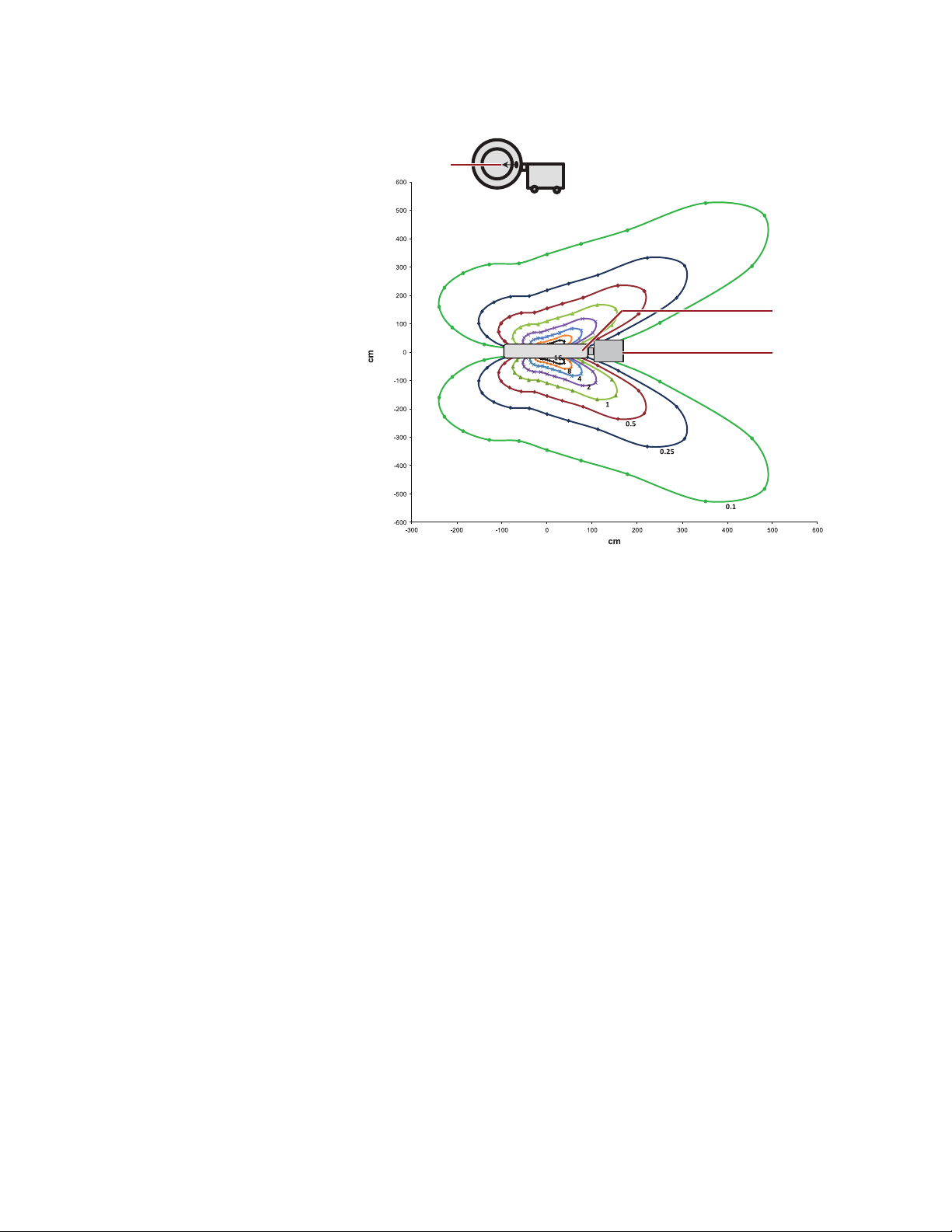
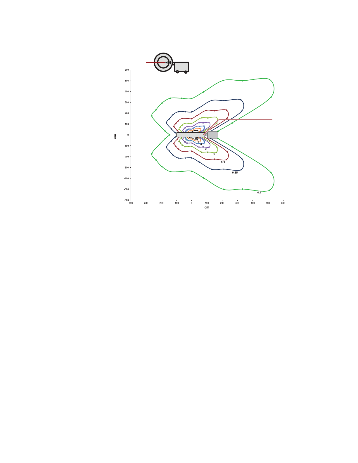
Figure 5: Isokerma map, values in µGy/Gy·cm
1
2
3
General Information and Safety
2
, 100 cm height, x-ray tube horizontal.
Safety
1 Radiation beam orientation, horizontal
2 X-ray focal spot
3 IAS Cabinet
Note: In Figure 5, the curves are presented for 0.1, 0.25, 0.5, 1, 2, 4, 8,
and 16 µGy/Gy·cm
2
.
19
Page 20
General Information and Safety
2
3
1
Safety
Figure 6: Isokerma map, values in µGy/Gy·cm
2
, 150 cm height, x-ray tube horizontal.
1 Radiation beam orientation, horizontal
2 X-ray focal spot
3 IAS Cabinet
Note: In Figure 6, the curves are presented for 0.1, 0.25, 0.5, 1, 2, 4, 8,
and 16 µGy/Gy·cm
Protective Clothing
The following removable protective devices are recommended in the facility’s radiation protection
policy:
• Protective shielding such as a lead apron, of not less than 0.25 mm lead equivalent, for protection
from stray radiation. Use protective devices such as thyroid collars, leaded glasses, and lead
shielding-screens, as necessary.
• If no lead-shielding screen is available, the operator should stand directly behind the IAS cabinet,
as illustrated in Figure
Note: Standing in this position is not a substitute for protective clothing such as lead aprons,
thyroid collars, and leaded glasses.
• Personnel should wear dosimetry badges per the facility’s radiation protection policy.
2.
2
.
20
Page 21

Radiation Safety
Operating Precautions
Warning: The O-arm™ O2 Imaging System produces ionizing radiation. Follow these safety
practices during its operation. Misuse of the system could harm the patient or operator.
Warning: Irradiation at high dose rates may interfere with pacemakers or other medical devices if
the device is within the x-ray beam.
• Use the equipment only in areas designated for its use.
• Have all personnel wear appropriate protective clothing and radiation monitoring devices while
using the equipment.
• Refer to the isokerma maps to view the typical x-ray exposure patterns that occur during imaging
sessions. For details on these maps, see “
• Be aware of visible and audible alerts that indicate when ionizing radiation is being produced by
equipment in the work area.
• Use the supplied patient spacer to ensure the patient is a safe distance from the x-ray tube. See
“
General Information and Safety
Safety
X-ray Exposure Patterns” on page 16.
The Patient Spacer” on page 118 for more information about how to use the patient spacer.
• Use the Radiation Disable button on the pendant (see page 52), or the Emergency Stop button
on either the Image Acquisition System (IAS) power control panel or pendant whenever the
system is not being moved or actively used to image anatomy. See the “
Reset Buttons” on page 51.
Emergency Stop and
General Exposure Precautions
X-rays are potentially hazardous. Take every precaution to reduce the radiation dose that patients
receive. In particular:
• During x-ray examination of pregnant women, take precautions to protect the embryo or fetus.
• Shield sensitive body organs, such as the eye or gonads.
• Follow safe operating procedures to avoid chronic radiation injury to users.
Caution: If using a contrast agent, follow the manufacturer’s instructions carefully to ensure highest
possible image quality and to avoid having to retake images.
Avoid Prolonged Exposure
• Avoid excessive exposure, which can cause acute skin burns or hair loss in patients.
• Avoid prolonged exposure. The O-arm™ O2 Imaging System is not intended for prolonged
radioscopically guided procedures, such as cardiac catheterization.
Source-to-Skin Distance
Before initiating fluoroscopy, make sure there is a minimum of 13 cm distance between the patient
and gantry cover on the x-ray source side; this ensures that there is at least 30 cm between the
patient and x-ray source.
21
Page 22

General Information and Safety
Safety
Warning: Exposure increases as the patient is positioned closer to the X-ray source. Failure to
maintain the minimum source-skin distance may result in increased radiation exposure to the
patient.
See also, “Maximum Permitted Exposure Rates” on page 283 for more information about local skin
dose level.
Use of Images in Image-Guided Treatments
Images acquired on the O-arm™ O2 Imaging System may be used for image-guided surgery. When
using O-arm
• Establish landmarks on the patient’s anatomy that you can use to verify the accuracy of the
positions displayed in images.
• Use these landmarks to verify the correct orientation of the images and the accuracy of the
system during navigation.
• Verify that the line-of sight between the tracker and tracking instrument remains clear and free of
obstruction.
Warning: Frequently confirm navigational accuracy and system responsiveness during live
navigation. Use the probe to touch bony anatomical landmarks and confirm that the locations
identified on the images match the locations touched on the patient. Failure to verify the landmark
locations on the image match the landmark locations on the patient may result in inaccurate
navigation. If accuracy degrades, re-register the patient.
Warning: Abort usage of the O-arm
are unintentionally rotated or smeared.
Caution: Materials in the x-ray beam, such as parts of the operating table or other accessories, may
have an adverse effect on image quality and increase the dose to the patient. It is important to
ensure that the maximum attenuation equivalent of tables, supports, and other accessories in the
x-ray beam are as low as reasonably achievable. It is recommended that selection of tables and
other accessories to be placed in the X-ray beam be made in consultation with a qualified medical
physicist.
™
images for image-guided surgery:
™
O2 Imaging System and contact Technical Services if images
Imaging Patients With Electronic Medical Devices
Patients with Electronic Medical Devices
The FDA has reported that x-ray imaging machines can cause adverse effects on patients with
implanted electronic medical devices such as:
• Pacemakers
• Defibrillators
• Neurostimulators
• Drug Infusion pumps
22
Page 23

General Information and Safety
Precautions During Imaging
Before taking images or beginning a scan, the operator should use scout views to determine if
implanted or externally worn electronic medical devices are present and if so, their location relative
to the programmed scan range.
For procedures in which the medical device is in or immediately adjacent to the programmed scan
range, the operator should:
• Determine the device type
• If practical, try to move external devices out of the scan range
• Ask patients with neurostimulators to shut off their devices temporarily while the scan is
performed
• Minimize x-ray exposure to an implanted or externally worn electronic medical device by:
– Using the lowest possible x-ray tube current consistent with obtaining the required image
quality
– Making sure that the x-ray beam does not dwell over the device for more than a few seconds
Warning: For procedures that require continuous scanning over an electronic medical device for
more than a few seconds, attending staff should be ready to take emergency measures to treat
adverse reactions if they occur.
Safety
Post-imaging
After scanning directly over the implanted or externally worn electronic medical device:
• Have the patient turn the device back on if it was turned off prior to imaging.
• Have the patient check the device for proper functioning, even if the device was turned off.
• Advise patients to contact their health care provider as soon as possible if they suspect their
device is not functioning properly after imaging.
Electromagnetic Compatibility
Overview
The O-arm™ O2 Imaging System emits low levels of radio frequency energy. To avoid interference
with or from other devices, use the equipment according to the instructions in this manual.
Complete tables for electromagnetic compatibility are in Chapter 10.
Electrical Interference from Other Devices
If interference from other devices affects the O-arm™ O2 Imaging System or the system experiences
unintended motor or x-ray actuation, immediately press the Emergency Stop button to disable x-ray
and motion functions. See “
Emergency Shutdown” on page 30.
23
Page 24

General Information and Safety
Safety
Radio Frequency Equipment
Portable and mobile RF communications equipment can affect medical electrical equipment.
Electrical Interference with Other Devices
If the O-arm™ O2 Imaging System seems to be causing interference with other devices, try the
following steps:
• To verify that the O-arm™ O2 Imaging System is the cause of the problem, turn it off and then
back on again while monitoring the affected device.
• If possible, relocate the affected device with respect to the O-arm™ O2 Imaging System or vice
versa.
• Plug the affected device’s power cord into a different power outlet so that it is on a different
branch circuit from the O-arm
• Check that the original power and MVS interconnect cables have not been damaged or replaced.
If the interference problem still exists, call the Medtronic technical service desk for assistance. See
“
Medtronic Technical Service” on page 10 for telephone numbers.
Electrical Safety
Observe the following safety procedures to avoid electric shock or serious injury to users and
patients and to avoid system malfunction.
Power Sources
• Only operate systems in designated-use areas with approved AC power outlets.
• Make electrical connections to other equipment while outside the patient environment.
Warning: Be aware that the Image Acquisition System (IAS) contains storage batteries that are a
source of strong electrical current, even when AC power is removed.
Warning: To avoid the risk of electric shock, this equipment must only be connected to a supply
mains with protective earth.
™
O2 Imaging System.
24
Caution: Do not plug the O-arm
other devices; its maximum current rating will use most of the branch circuit's capacity.
™
O2 Imaging System into the same branch circuit that supplies
Equipment Connections
The O-arm™ O2 Imaging System is only intended for connection to other IEC 60950-1 or IEC 606011 certified equipment. The user is responsible for ensuring that any equipment configuration still
complies with 60601-1 system requirements.
Page 25

General Information and Safety
Potential Equalization Connector
The IAS and MVS include a equipotential ground point (potential equalization connector), see Figure
14 on page 46, and Figure 27 on page 64. This connector can be used to connect the O-arm to a
common ground to reduce potential differences between equipment or facilities. In all cases
interconnected equipment used within the patient environment must meet the leakage current
requirements of IEC 60601-1, or national equivalents.
Equipment Handling
• Do not remove assembly covers. Only trained service representatives should service or repair
the equipment.
Warning: Do not remove cabinet covers. Certain electrical circuits inside the equipment use
dangerously high voltages. Failure to heed this warning could result in serious injury or death.
• Do not bypass, jumper, or otherwise disable the safety interlocks.
• Do not place food or beverage containers on the equipment. If spilled they can cause short
circuits.
• Remove power to the equipment before cleaning. Refer to “Powering Down and Storing the
System” on page 237 for cleaning instructions.
Safety
Isolating the Mains Power supply
Mains power can be disconnected from the IAS by disconnecting the MVS interconnect cable from
the IAS connector panel. See “
MVS remains powered as long as it is plugged into the facility power outlet.
Mains power into the MVS may be disconnected from the system by unplugging the AC power cord
from the facility power outlet.
Once the MVS is unplugged from the facility power outlet, the MVS remains powered for a short
duration to facilitate moving the MVS from one location to another within a time period of 10 minutes
or less.
IAS Connector Panel” on page 46 for more information. However, the
Ground Fault Alarm
If the operating room has a ground fault alarm and the alarm is actuated:
• Do not operate the system.
• Call the Medtronic technical service desk for assistance. See “Medtronic Technical Service” on
page 10.
Caution: When working in the vicinity of the O-arm™ IAS and MVS, use care to avoid tripping over
the power and interconnect cables.
Ground Fault Detector on Battery
The O-arm™ O2 Imaging System contains an internal ground fault detector on the battery. If the
battery system detects a ground fault (current flowing to the middle of the battery stack), the
generator contactor is switched off and an error message is recorded in the system’s log file.
25
Page 26

General Information and Safety
Safety
Electrical Fire Safety
Ensure that your emergency procedure for handling an electrical fire includes these steps:
1. Press the Emergency Stop button to disable x-ray and motion functions.
2. Remove electrical power to the system by placing the power switches on the IAS and MVS to
their off positions.
3. Unplug the MVS power cord from the AC wall receptacle.
4. Evacuate personnel from the area.
5. Use a fire extinguisher that is approved for use on electrical fires.
Warning: Make sure that a fire extinguisher approved for use in an electrical fire is available in
the room where the O-arm
extinguisher can result in electrical shock and burn hazards.
6. Call the local fire department for help.
Mechanical Safety
Positioning Safety
The O-arm™ IAS (gantry plus positioner) is a motorized assembly that is capable of moving in all
three (x, y and z) planes of reference and pivoting about the three axes with tilt and wag motions. It
also contains a telescoping door assembly. Follow these precautions when moving the O-arm
• Observe the immediate surroundings when operating the gantry to avoid pinching or collision
with a person or object.
• Use care when working around the gantry to avoid unintentional motor actuation.
• Do not place objects on the gantry or bump or lean against it.
• Observe and prevent articles of clothing from getting caught in moving parts.
Warning: Do not use the O-arm™ O2 Imaging System if the supplied ratchet wrench and T-shaped
rotor alignment tools are not present. These tools are required for opening the Image Acquisition
System (IAS) door manually in case of an emergency. These tools are stored in the utility drawer
on the Mobile View Station (MVS). For instructions on opening the IAS door manually, see page
255.
™
O2 Imaging System is used. Use of the wrong type of fire
™
IAS:
26
Warning: When the Image Acquisition System (IAS) is not in use, or if it is unattended, engage the
Emergency Stop button. See “Emergency Shutdown” on page 30.
Warning: Keep clear of the door when it is partially open or while opening or closing. Do not move
the O-arm
Warning: Do not drive the Image Acquisition System (IAS) or move the gantry without being aware
of all objects, equipment, obstacles or persons that may collide with the device as it moves.
™
Image Acquisition System (IAS) over the patient unless the door is fully opened.
Page 27

General Information and Safety
Collision Zone Warning
If you move the IAS gantry toward the dock base, a Collision zone warning will appear on the
pendant screen to warn the user that further movement of the IAS gantry could potentially collide
with the dock base (see Figure
motion stops automatically. To restart motion of the IAS gantry, move it up and/or away from the
Collision zone by unpressing and pressing the gantry motion buttons on the pendant. For
instructions on using the pendant to position the gantry, see “
and Beam Positioning” in Chapter 6.
7). When the IAS gantry enters the Collision zone, the IAS gantry
Pendant Buttons for Gantry Movement
Figure 7: Collision zone warning
Safety
Checking the System After A Collision
If a collision occurs during transport or use, confirm functionality of the system using the performance
checks detailed in
Contact Medtronic technical service if any functionality has been affected by the collision.
Chapter 9 (see “Performance Checks and Maintenance” on page 242 for details).
Transport Safety
When moving the O-arm™ IAS, use care to avoid colliding with or running over objects or people. All
users must be familiar with stopping, steering, and movement controls. Never drive the O-arm
from the side - always stand to the rear.
Warning: The Image Acquisition System (IAS) weighs approximately 885kg (1,950 lbs). Move the
IAS slowly using the battery-powered drive transport wheels. Do not disengage the drive wheels
during transport, especially on an incline. Use special care when crossing thresholds and moving
up or down ramps. Be aware of all obstacles and people along the path. Collision with people or
physical objects can result in personal injury or equipment damage.
Warning: The gantry must be docked when you move the Image Acquisition System (IAS). Use
special care on steep slopes (>5º) and when crossing ramps and thresholds.
Caution: Transportation of the O-arm
special handling, packing, and strapping procedures to prevent injury to movers or damage to
the equipment. Contact Medtronic technical service for detailed instructions.
™
O2 Imaging System between facilities in a truck requires
™
IAS
Caution: Engage the lateral shift wheels only on a level surface. The IAS will roll sideways if the
lateral shift wheels are engaged on a tilted surface.
27
Page 28

General Information and Safety
Safety
Pinch Hazard
Warning: Keep body parts clear of the gantry door whenever the door and door sidewalls are
closing. Keep body parts clear of the gantry itself when it is in motion.
General Use Safety
Lasers
Complies with 21 CFR 1040.10 and 1040.11 except for deviations pursuant to Laser Notice 50, dated
June 24, 2007.
The wireless mouse emits Class 2 laser light.
Warning: Do not point laser radiation at audience.
Caution: Laser radiation. Do not stare into beam. Class 2 laser product.
The laser alignment lights emit Class 1M laser light.
Do not view the beam of the laser alignment lights directly with optical instruments such as
binoculars, telescopes, or microscopes.
Caution: The laser alignment lights emit Class 1M laser radiation. Do not view directly with optical
instruments.
Infection Safety
The O-arm™ O2 Imaging System is intended to be used in surgical procedures. The MVS and
chassis should be cleaned as described in “
To protect the sterile field, drape the O -arm™ gantry as described in “Using the Door and Preparing
the Gantry” on page 115.
Warning: To prevent cross-contamination, always handle, transport, and reprocess devices that
contact the central nervous system separately from other devices.
Cleaning” on page 238.
Enclosure Integrity
The X-ray gantry (the “O”) is enclosed in protective enclosures (skins) made of a non-conductive
plastic material. This protective enclosure isolates the patient and operator from contact with
components that could present risks of electric shock, burns or pinching of fingers or hands. If the
protective enclosure is compromised in any way, the system should not be used unless it can be
confirmed that the damage is purely cosmetic in nature.
28
Explosion Safety
Warning: Do not operate the O-arm™ O2 Imaging System in the presence of flammable anesthetics,
explosive liquids or gases. If such substances are detected, follow the instructions below. Failure
to heed this warning could result in serious injury or death.
Warning: The O-arm
™
O2 Imaging System is not intended for use in an oxygen rich environment.
Page 29

General Information and Safety
Safety
If the presence of flammable anesthetics, explosive liquids or gases are detected in the vicinity of
the O-arm
Do not plug in or turn on the equipment if such substances are detected prior to start up. If they are
detected after the system is turned on, do not immediately turn off or unplug the equipment.
Evacuate all personnel and ventilate the area before turning off the system.
™
O2 Imaging System, cease operations immediately.
Avoiding Ingress of Fluids
Fluids, such as antiseptics, cleaning solutions, or bodily fluids, may damage internal components if
they enter the equipment. Conductive fluids that contact active circuits may cause short circuits and
electrical fires. To avoid these mishaps:
• Do not apply excessive amounts of fluid when cleaning.
• Use drapes, if necessary, to protect equipment when performing procedures.
Note: Draping equipment may restrict airflow to components and vents that cool the equipment.
Drape equipment and cover vents only during procedures when appropriate for bioburden
control or exposure to fluids is expected. Remove the drapes as soon as the procedure
allows.
Warning: The O-arm
into the equipment, remove power and disconnect the Mobile View Station (MVS) power cord.
Do not operate the system until it can be cleaned and inspected by a qualified service
engineer.
™
O2 Imaging System is not rated for watertight operation. If liquids drip
Environmental Safety
The batteries and x-ray assembly are hazardous to the environment. Dispose of them in accordance
with local environmental regulations. Refer to your local agencies for disposal instructions.
Emergency Procedures
Preparation and Training
Have all personnel who use the O-arm™ O2 Imaging System learn and practice the procedures for
both manually and electronically opening the gantry door, so that they can perform them quickly in
an emergency.
Patient Requires CPR
Prior to beginning any procedure, consider your ability to perform CPR on the patient, if necessary.
The gantry may be moved in two ways that allow access to a patient requiring CPR.
• Using the wag, tilt, and longitudinal controls, move the gantry into a position that allows sufficient
access for CPR. See “
• Using the Lateral Shift capability, push the IAS out of the way of persons performing CPR.
Follow the directions on page 116 for positioning the gantry to allow CPR.
Gantry Movements” on page 128.
29
Page 30

General Information and Safety
Safety
In Case of Emergency
• Ensure the safety of the patient and medical personnel first, and then the safety of the equipment.
• Do not leave a patient unobserved in the area of the equipment.
• If there appears to be danger to the patient, press either of the Emergency Stop buttons on the
IAS, except in the presence of flammable anesthetics, explosive gases or liquids. See “Explosion
Safety” on page 28.
• Follow safety procedures for the situations described in this chapter.
• Contact an authorized Medtronic Service Representative to report the incident and receive
further instructions.
Equipment Failure
If any of the equipment controls fail to respond as indicated in this manual, or if a circuit breaker trips:
• Perform the troubleshooting procedures detailed in Chapter 9. For MVS problems, see page 259.
For IAS problems, see page 261.
• If the equipment problems persist, cut off electrical power to the system. Turn off the IAS and
MVS by pressing and holding their Power buttons for 5 seconds.
• Unplug the MVS power cord from the wall.
Warning: The Image Acquisition System (IAS) contains storage batteries that are a source of
strong electrical current, even when AC power is removed.
• Notify the Medtronic technical service desk. See “Medtronic Technical Service” on page 10.
• Do not operate the equipment until the service technician confirms that it is operating properly.
Emergency Shutdown
To disable the x-ray and motion functions of the O-arm™ O2 Imaging System at any time, press
either of the Emergency Stop buttons (see Figure
while the other is located on the IAS Power Control panel (2).
Warning: Press the Emergency Stop button any time that unexpected movement or X-ray
actuation occurs.
Familiarize yourself with the control functions for the control panel (on page 47) and the pendant (on
page 50) prior to operating the system.
Refer to “Unintended Emergency Shutdown (E-Stop)” for instructions on how to recover from
unintended activation of E-Stop.
8). One button is located on the pendant (1),
30
Page 31

Figure 8: Emergency Stop buttons
Resetting the Emergency Stop
General Information and Safety
Safety
To return the system to normal operating conditions, press the Emergency Stop Reset button (1)
on the pendant.
Figure 9: Emergency Stop Reset button
31
Page 32

General Information and Safety
Safety
32
Page 33
2 System Overview
This chapter gives an overview of the main O-arm™ O2 Imaging System components and
capabilities.
Introduction to the System
Overview
The O-arm™ O2 Imaging System is a mobile x-ray system designed for surgical applications, preoperative planning, intraoperative imaging, and post-operative assessment. The system provides
basic fluoroscopy and multi-plane 2D imaging, and features 3D volumetric imaging with fast 3D
reconstruction displays in three orthogonal views.
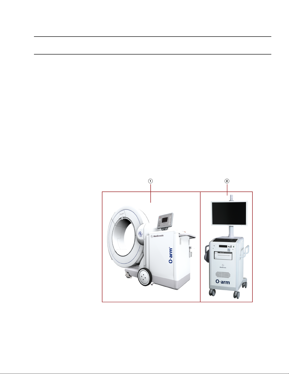
Main Components
Figure 10: The O-arm
™
O2 Imaging System (IAS = 1; MVS = 2)
33
Page 34
System Overview
Introduction to the System
The system, shown in Figure 10, consists of two main assemblies:
• The Image Acquisition System (IAS)
• The Mobile View Station (MVS)
The IAS and MVS are connected by the MVS’s interconnect cable (not shown) that provides power
to the IAS and transmits signal data between the assemblies.
The IAS has a motorized battery-powered transport system for ease of movement and positioning.
The Image Acquisition System (IAS)
Main Components
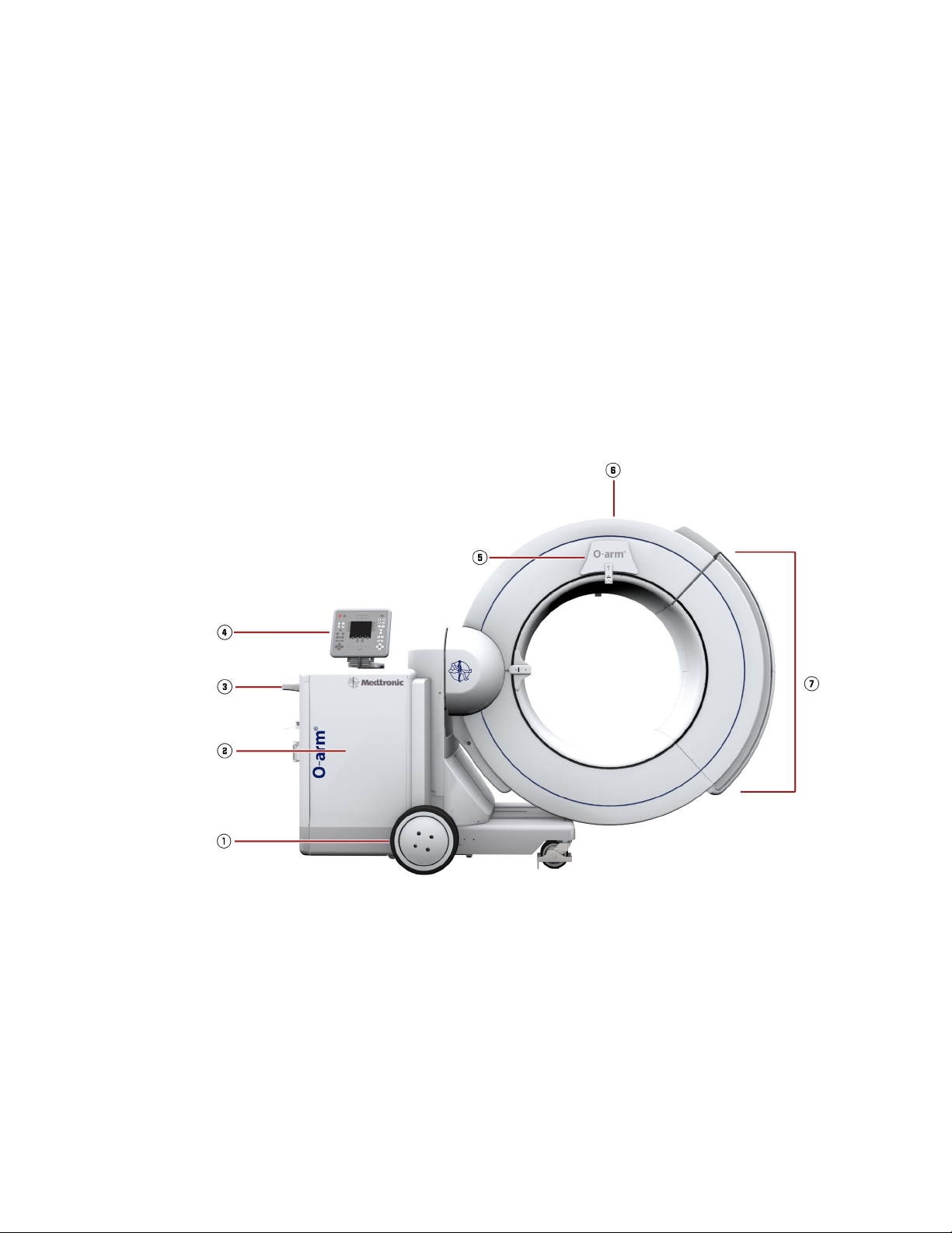
The main components of the IAS are shown in Figure 11.
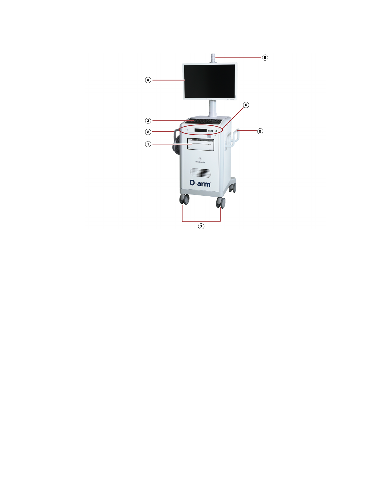
Figure 11: The Image Acquisition System, or IAS
34
The Gantry
The gantry 6 contains an inner ring with a rotor unit that includes the x-ray source and detector.
The outer portion contains a telescoping door
patient access and positioning over the operating table.
A Light Ring on the gantry indicates the position of the x-ray source and the detector so that you can
align the x-ray beam path.
The navigation tracker 5, which is an optional accessory, is installed on the top of the gantry. The
navigation tracker provides functionality for referencing the location of the O-arm
acquisition and then sending that information to an image guided surgery system
7, shown closed, which accommodates lateral
™
during image
.
Page 35

System Overview
Introduction to the System
The Cabinet
The cabinet 2 has the user interface called the pendant 4, the robotic motion control unit, a
motorized mechanics assembly, and an energy storage unit containing the battery power supply
generator. Using the buttons on the pendant, you can move the gantry in lateral, longitudinal, up and
down, wag, Isowag™, and tilt directions. Refer to “
Gantry Movements” on page 128.
Positioning Capabilities
Battery-powered rear wheels 1 allow you to move the IAS by means of the transport handle 3.
Refer to “
For extra maneuverability in tight quarters, an additional pair of wheels can be activated to allow the
IAS to be manually moved sideways. Refer to “
Using The Transport Handle” on page 93.
Moving the IAS Laterally” on page 144.
Standalone Mode
In normal operation, the IAS receives its power via the MVS interconnect cable. When disconnected
from the MVS, the IAS operates in standalone mode. In this mode, the IAS receives its power from
storage batteries to perform all positioning and movement functions. The x-ray generator is
deactivated in the standalone mode, so it is not possible to take images.
Laser Alignment Lights
The IAS is equipped with laser alignment lights for helping to position the path of the x-ray beam on
the anatomy that you want to scan. For details, see “
The Mobile View Station (MVS)
General Components
The MVS includes an image processor and user interface that display the images produced by the
IAS.
The Laser Alignment Lights” on page 140.
35
Page 36
System Overview
Introduction to the System
Figure 12: Mobile View Station, or MVS
Hand Grips and Wheels
Two hand grips 2 and four swivel wheels 7 help you move the MVS. The wheels have foot
pressure brakes to lock the unit in place.
Keyboard
The MVS has a standard keyboard 3 for data entry, with special keys for manipulating display and
imaging parameters, and a touch pad that allows you to move the cursor and make selections. See
“
The Keyboard and Wireless Mouse” on page 58.
Monitor
The 30-inch, high definition, LCD, flat panel monitor 4 displays patient exam data and images. See
“
The Monitor” on page 57. A second monitor can be connected for remote viewing. See “Connecting
a Second Monitor” on page 96.
DVD/CD-RW Drive
The MVS includes a DVD/CD-RW drive on the connector panel (6) for exporting patient image data
to a DVD/CD. For instructions, see “
Exporting Images to External Media” on page 215.
Video Graphics Printer (Optional)
36
An optional printer (1,Sony
printer to print the active image on the MVS monitor onto transparency film or paper.
®
UP-991AD printer) may be purchased with your system. Use this
Page 37

System Overview
Introduction to the System
Power Control Panel
The power control panel 6 contains the power button, AC power indicator light, DVD/CD RW drive,
receiver for wireless mouse, and two USB ports for exporting images to removable storage media.
See “
The MVS Power Control Panel” on page 56.
Storage Drawer for Tools
The storage drawer on the right side of the MVS contains customized storage cutouts for three
different tools:
• T-shaped rotor alignment pin tool
• Ratchet wrench
• Patient spacer
If the IAS is unresponsive, use the T-shape rotor alignment pin tool and the ratchet wrench to open
the gantry door manually (see “
Spacer is used prior to patient scanning to ensure that there is a safe distance between the patient
and the X-ray source (see “
Manually Opening the IAS Gantry Door” on page 255). The Patient
The Patient Spacer” on page 118 ).
Storage Holder for Footswitch
The storage holder on the bottom left of the MVS is intended to store the footswitch when it is not
being used.
X-ray Activation Light
The x-ray activation light 5 on top of the MVS monitor illuminates when any of the following modes
are activated:
• Imaging modes (2D, M-2D, 2D Long Film [Optional image mode], or 3D); or
• Gain calibration modes (Fluoro Gain or Rad Gain)
This light remains illuminated until the active imaging session or gain calibration session is finished.
The activation light also indicates the x-ray status.
Table 3: Description of x-ray activation lights
Light X-ray Status
Solid Green X-ray is off, but the system is ready to start acquiring images once the user
activates the x-ray via the footswitch or handswitch.
Blinking Green System is about to start x-ray. Once the light starts blinking, no further action
is required before the x-ray starts.
Solid Yellow X-ray is on and the system is actively acquiring images.
USB Ports
Two (2) USB ports on the connector panel allow you to export images to removable storage media.
Refer to “
Exporting Images to External Media” on page 215.
37
Page 38

System Overview
Introduction to the System
Acquisition Modes
Overview
The O-arm™ O2 Imaging System has four main acquisition modes that produce ultra-high resolution
images:
• 2D Fluoroscopy Mode (2D)
• Multi-plane 2D Fluoroscopy Mode (M-2D)
• 2D Long Film Scan (2D) (Optional)
• 3D Mode (3D)
To activate any of these acquisition modes, use the handswitch or footswitch (see page 53). If you
transfer between acquisition modes (e.g. 2D to 3D), wait at least one second before pressing and
holding the footswitch pedal to acquire the images in the new selected mode.
When not acquiring images, you can use the system to set up patient exam information, review and
annotate patient images, and export patient data.
2D Modes
Dose Reporting
Dose Reporting tracks patient exposure to radiation generated by the O-arm™ O2 Imaging System.
For more information, see “
Dose Reporting” on page 196.
2D Fluoroscopy Mode
This acquisition mode (also referred to as 2D mode) uses pulsed x-rays at up to 30 frames per
second to produce high resolution, real-time images. To select either standard fluoroscopy or high
level fluoroscopy (HLF), use either the handswitch or footswitch. To select low level fluoroscopy
(LLF), first press the Low Level softkey on the pendant and then press the left footswitch pedal or
top handswitch button. Standard fluoroscopy is the default selection.
A Last Image Hold (LIH) in 2D mode leaves the last live image of the pulsed sequence on the MVS
screen once scanning is completed or the user discontinues scanning. To get a stable 2D image,
wait at least 2 seconds. The last image can be saved and recalled at a later time for review.
These image processing functions are available in the 2D mode in both the live fluoroscopic mode
and LIH:
• Edge enhancement
38
• Rotation/mirroring
• Contrast/brightness
• Video invert
Refer to “Using the 2D Mode” on page 153 for a detailed description of operating this mode.
Page 39

System Overview
Introduction to the System
Low Level Fluoroscopy (LLF) Mode
Low level fluoroscopy (LLF) provides reduced dose imaging in the 2D Fluoroscopy mode. This lower
level of radiation, approximately half the dose, is achieved by changing the pulse rate from 30 per
second to 15 per second.
LLF achieves lower dose by decreasing the frame rate per second from 30 to 15, and therefore the
temporal resolution will be less in low level mode.
Multi-plane 2D Fluoroscopy Mode
In this acquisition mode, you can acquire a set of 2D fluoroscopy images, either standard or high
level fluoroscopy (HLF), at previously stored gantry positions.
You can store up to four separate gantry positions and their associated settings for later call-up. You
can set a fifth preset ‘Park’ position for the gantry away from the surgeon’s area. Refer to “
Positions and Acquisition Settings” on page 163 for a detailed description on the use of these
buttons.
All the image processing functions available in the standard 2D mode are also available in this mode.
Storing
2D Long Film Mode (Optional)
The 2D Long Film mode provides functionality for acquiring an intraoperative linear X-ray scan. In
this mode, the O-arm
during acquisition between the positions stored in memory presets 1 and 2. For details, see “
2D Long Film Mode (Optional)” on page 168.
™
O2 Imaging System scans while the gantry moves along the left/right axis
3D Modes
Overview
In 3D acquisition modes, the O-arm™ IAS creates a series of pulsed x-ray exposures throughout a
complete 360-degree rotation of the gantry rotor. The rotor spins at 30
at 30 frames per second, and captures approximately 391 projections. The system stores these
exposures and uses a reconstruction algorithm to develop a 3-dimensional volume representative of
the patient’s anatomy from them. The image is displayed on the MVS monitor screen as a high
resolution display in the axial, coronal, and sagittal planes.
The reconstructed volume used by the reconstruction algorithm is a cylinder with different diameters
for each field of view setting:
• For 20 cm field of view, the cylinder has a diameter of 212 ± 1 mm and a length of 160 ± 1 mm.
• For 40 cm field of view, the cylinder has a diameter of 397 ± 1 mm and a length of 160 ± 1 mm.
Using
° per second, acquires images
The voxel resolution is 512 x 512 x 192
Additional Imaging Modes for 3D
In addition to standard 3D mode, the O-arm™ O2 Imaging System has four different modes for
acquiring 3D images:
39
Page 40

System Overview
Introduction to the System
Low Dose 3D Mode
Low Dose 3D mode is designed to provide an additional preset setting for standard 3D acquisitions
with a lower overall dose reduction of at least 35% from the standard acquisition protocols, for cranial
and spinal applications. The rotor spins at 30
and captures approximately 391 projections. For more information see “
page 180.
High Definition 3D (HD3D) (Optional)
High Definition 3D (HD3D) mode provides improved image quality over that of regular 3D. The rotor
spins at 15
approximately 745 projections.
Enhanced Cranial 3D Mode (Optional)
Enhanced Cranial 3D mode enables you to take images of higher quality than those acquired in
regular 3D mode. It has the same spin velocity and frame rate as HD3D mode, but uses different
kVp and mA settings and a different reconstruction algorithm. It is designed for cranial images only.
See “
Stereotaxy 3D Mode (Optional)
° per second, acquires images at 30 frames per second,
Low Dose 3D Mode” on
°per second, acquires images at a rate of 30 frames per second, and captures
Dose Settings for Head” on page 186.
Stereotaxy mode supports high definition 3D (HD3D) volumetric imaging of high contrast landmarks
of stereotactic localizers for cranial procedures. For instructions, see “
Scans” on page 188.
Optional 3D Features
Multiple Field of Views
The O-arm™ O2 Imaging System supports 3D volumetric imaging in 20 cm and 40 cm field of views.
The 40 cm field of view improves visualization for large anatomical regions, and supports imaging
high contrast landmarks of stereotactic localizers in Stereotaxy mode. For details on using this
feature, see “
Oblique Slicing in 3D
This feature allows you to make adjustments to images taken in 3D mode if the patient’s body and
the imaging axes are slightly misaligned. Adjustments can be made to the axial, coronal, and sagittal
views. Refer to “
Storing Collimator Positions in 3D
In normal 3D mode, the collimator is wide open and not adjustable. This feature allows you to adjust
the Collimator and store that Collimator position in memory to be used later. This is useful when you
want to isolate a small specific area of interest in the anatomy. It also reduces the amount of scatter
in the room and radiation exposure to the patient. Refer to “
page 183.
Acquiring 3D Stereotaxy
3D Image Acquisition” (page 182) and “Acquiring 3D Stereotaxy Scans” (page 188).
Advanced Imaging Features in 3D Mode” on page 194.
Using Preset Collimation Settings” on
40
Page 41

X-ray Options
System Overview
Introduction to the System
Maximum Intensity Projection (MIP) View in 3D
MIP is a 3D rendering of the volume that provides a 360° view for advanced viewing. MIP is available
in the 3D mode display. Refer to “
The two x-ray types used by the system are:
• Pulsed Fluoroscopy - for both the 2D and 2D multi-planar application modes
• Pulsed Exposure - for the 2D Long Film (optional) and 3D modes
Advanced Imaging Features in 3D Mode” on page 194.
Pulsed Fluoroscopy
Standard fluoroscopy, High Level Fluoroscopy (HLF) and Low Level Fluoroscopy (LLF) are available
in the pulsed fluoroscopy modes. Standard fluoroscopy is the default.
For lower dose delivery, use LLF. To select LLF, first press the Low Level softkey on the pendant,
then press either the left footpedal or top button on the handswitch. After pressing the Low Level
softkey, the Auto Brightness feature is activated automatically. See “
Using the Softkeys” on page 157.
Optimizing 2D Image Quality
For improved image quality, you can use either the handswitch or footswitch to select HLF Standard
fluoroscopy. As with standard fluoroscopy, the user can press the Auto Brightness softkey to
manually activate the feature.
• The pulse rate for both standard fluoroscopy and HLF is 30 pulses/second.
• The pulse rate for LLF is 15 pulses/second.
• Continuous HLF time is limited to 30 seconds. Once that time is reached, the x-ray exposure
automatically stops.
Pulsed Exposure
Pulsed exposure is used for 2D Long Film and 3D imaging to reduce motion blur and is produced by
reducing the x-ray pulse width and increasing the exposure.
The pulse rate for pulsed exposures is 30 pulses/second.
The acquisition time is limited to 13 seconds per single 3D scan, and 26 seconds for HD3D,
Enhanced Cranial, 40 cm FOV, and Stereotaxy single panel scans. Once that time is reached, the
x-ray exposure automatically stops.
Patient Exam Data Capabilities
Data Entry
You can input patient exam information using the MVS keyboard. Refer to “Entering Patient
Information” on page 98. Options are: entering the names of the patient and physician, placing the
patient into a scheduled exams list, and integrating the patient’s images into saved exams records
that are stored in the system’s database.
41
Page 42

System Overview
Introduction to the System
Patient Data Recall and Review
For each patient, you can recall the complete exam record, which lists each of the studies that were
performed on that patient. Refer to “
The system allows you to open an individual patient study, view the image series for that study, and
select individual images to open for review. You can export images to external media or across a
network in DICOM format, save them to a snapshot file, or print them, if you have a video graphics
printer on your system.
DICOM Export Capability
The system has the capability of exporting both 2D images and 3D data sets in DICOM format across
a network to a picture archiving and communication systems (PACS) server or to another DICOM
device.
You export DICOM images via the MVS user interface. See “Exporting Images to External Media”
on page 215 for complete details.
Export to External Memory Devices
Accessing and Reviewing Patient Exams” on page 207.
You can save any image that appears on the MVS monitor screen to a snapshot file and later transfer
it, and other snapshots, to a CD or USB flash drive storage device. See “
External Media” on page 215.
Exporting Images to
Image Annotation
All x-ray images produced by the system are displayed on the MVS with the following data:
• Patient Information: patient name and ID
• Exam Information: date and time of the exposure
• X-ray Information: dose rate and cumulative dose display
• Image Processing and Edge Enhancement: brightness and contrast values
You can also add annotations to images, using the annotation feature. See “Image Annotation” on
page 219. These annotations are saved with images as overlays.
Image Stitching
The O-arm™ O2 Imaging System software offers image stitching capabilities for 2D images, so that
images can be stitched together to create a longer image of the patient’s anatomy than can be
acquired in one exposure. See “
Image Stitching”on page 232.
42
Image Guided Surgery
The O-arm™ O2 Imaging System can be used in conjunction with Medtronic Image Guided Surgery
(IGS) Systems to provide IGS capabilities in surgical procedures. The setup for this requires an
™
O-arm
Configuring an Image Guided Surgery (IGS) System” on page 82.
O2 Tracker Kit (BI-750-00027), and a network interface procedure. See “Connecting and
Page 43

System Overview
Introduction to the System
Video Graphics Printer (Optional)
An optional printer (Sony® UP-991AD), located in the MVS, can print any image appearing on the
active pane of the MVS monitor onto transparency film or paper. See “
page 56.
Video Graphics Printer” on
43
Page 44

System Overview
Introduction to the System
44
Page 45

3 Controls and Indicators
This chapter describes the controls and indicators on the O-arm™ O2 Image Acquisition System
(IAS) and Mobile View Station (MVS).
IAS Controls and Indicators
Control Locations
Figure 13 shows the locations of controls on the O-arm™ Image Acquisition System.
Figure 13: Location of IAS controls and indicators
Number Component Description
1 IAS connector panel IAS positioning.
2 Handswitch X-ray operations
3 Transport handle IAS transport
4 IAS control panel Power on/off
5 Pendant Gantry positioning, x-ray operation
The footswitch is not shown in Figure 13. It connects at the O-arm™ IAS connector panel, but can
be disconnected and stored when not in use.
45
Page 46

Controls and Indicators
IAS Controls and Indicators
IAS Connector Panel
Overview
The IAS connector panel is located at the bottom front of the IAS. This panel contains the key switch,
the port for connecting the MVS interconnect cable, and the ports for attaching the handswitch,
footswitch, and second pendant.
Figure 14: The IAS connector panel
46
Number Description
1 Dongle that fits over the J1 port when not in use. Remove this dongle to
connect the second pendant.
2 Footswitch port
3 Equipotential ground point
4 Second pendant port
5 Key switch port
6 Handswitch port
7 MVS interconnect cable port.
The Key Switch
Insert the supplied key into the key switch to enable the power-up and shutdown of the IAS.
Page 47

• To enable power-up of the system, turn the key counter-clockwise to the green position. This
enables the system to be powered-up for full operation, or shutdown via the Power button (blue).
• To disable the system, turn the key clockwise to the red position. This disables all IAS functions
(except battery charging), and initiates a safe shutdown of the system if the system is currently
powered on.
Caution: When the system is unattended or not in use, remove the key from the key switch to
prevent the IAS from being powered up.
The IAS Power Control Panel
Controls and Indicators
IAS Controls and Indicators
Overview
The IAS power control panel is located directly in front of the transport handle. This panel contains
a set of buttons and indicator lights for turning the system on and off, checking the status of
remaining battery charge, and disabling the system’s x-ray and motion functions immediately in case
of an emergency.
Figure 15: The IAS power control panel
Number Component Description
1 Power Button Press this button to power the IAS system on and off. To turn off the system,
press and hold this button for 5 seconds.
2 AC Power Indicator When illuminated green, this icon indicates that AC power is being used to
charge the batteries.
3 Battery Charge Status Button If the system is turned off, press this button to check the available charge of
the IAS system’s battery power via the battery charge indicators.
47
Page 48

Controls and Indicators
IAS Controls and Indicators
Number Component Description
4 Battery Charge Indicators lndicates the level of remaining battery charge. For details, see “Battery
Level Indicators” on page 48.
5 Emergency Stop Button In an emergency situation, press this button to disable all motion and x-ray
functions immediately. To reset the system, press the reset button on the
pendant (see Figure 16).
Power Control Panel Indicators
The status of the IAS power control panel indicators is affected by a combination of system factors
that include:
• The key switch position
• The MVS interconnect cable connection
• The MVS power state
Battery-Powered Transport Activation
The IAS can be moved using its battery-powered transport assist system when the IAS system is
powered on and the Emergency Stop button is not pressed.
Battery Charging
Note that the IAS batteries are charging whenever the MVS is plugged into an active power outlet
and connected via the MVS interconnect cable to the IAS. It is not necessary for the key switch to
be turned on or for the MVS to be running. See “
Charging the Batteries” on page 241.
Battery Level Indicators
The battery level indicators on the IAS power control panel specify the current charge for the motion
batteries and x-ray batteries. The following table defines these indicator symbols:
Table 4: Description of battery indicator symbols
Symbol Color Remaining Charge
Blue 100% (at least 395 VDC).
Blue 80% (between 390 and 394.9 VDC).
48
Blue 60% (between 385 and 389.9 VDC).
Page 49
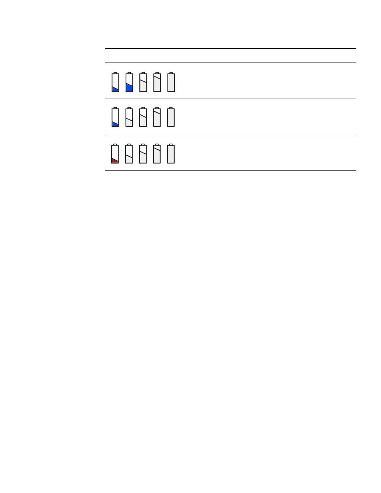
Controls and Indicators
IAS Controls and Indicators
Symbol Color Remaining Charge
Blue 40% (between 380 and 384.9 VDC).
Blue 20% (between 375 and 379.9 VDC).
Red 10% (between 360 and 374.9 VDC). Imaging must be
If the battery charge falls under 375 VDC, the system activates the following warnings:
• An audible alarm tone.
• A red battery indicator light appears on the IAS power control panel
• A low battery indicator symbol appears on the pendant screen.
• A warning message appears on the MVS screen: “Battery voltage critically low.”
If this condition occurs, shut down the system as soon as possible and charge the batteries. If the
battery charge fall under 365 VDC, the system shuts down automatically.
stopped at this level.
Battery Fault
If one of the batteries becomes defective, the system activates the following warnings.
• The first battery icon on the left changes from blue to flashing red.
• A warning message appears on the MVS screen: “Individual battery failure.”
If this condition occurs, service the batteries as soon as possible.
Complete System Startup and Shutdown
For the system to be fully functional, the IAS and the MVS requires the following setup:
• The MVS and IAS must be connected to each other via the MVS’s interconnect cable.
• Both the MVS and IAS must be turned on.
To shut down completely, they must both be shut down individually. The IAS enters the standalone
mode whenever it is on and the MVS is switched off. Refer
for details regarding startup and shutdown.
Chapter 5 and Chapter 9, respectively,
Emergency Stop
Press the Emergency Stop button on the IAS power control panel to disable the x-ray and motion
functions immediately. To restart the system after an emergency stop, press the Emergency Stop
Reset button on the pendant before pressing the Power button to restart the system.
49
Page 50

Controls and Indicators
IAS Controls and Indicators
The Pendant
Overview
With the exception of startup, you control all functions pertaining to the gantry from the pendant.
Use the pendant to control the gantry’s motion, the x-ray modes, and other factors pertaining to the
x-ray image.
An optional remote pendant may be ordered (REF # BI-710-00529) that plugs into the J1 port on the
IAS connector panel (see Figure
operator to stand away from the x-ray source during an imaging session. To order this accessory,
contact Medtronic technical service.
14 on page 46). The purpose of this remote pendant is to allow the
Figure 16: The pendant
50
Page 51

Controls and Indicators
IAS Controls and Indicators
Number Description
1 Emergency stop and reset button
2 Image mode selection buttons (for the optional 2D Long Film mode, press [2D] and
then Long Film softkey)
3 Softkeys and display
4 Transport brake set/release
5 Gantry and IAS positioning controls
6 X-ray generator controls and indicators
7 Radiation disable button
8 Memory preset buttons. Pressing the [M] button will also slow the gantry motion.
9 Collimator adjustment controls. This feature is disabled in the optional 2D Long Film
mode.
0 Mirror/Flip image, contrast, and brightness. The Mirror/Flip image features are
disabled in 3D mode and in the optional 2D Long Film mode.
- Save image
= AP/LAT (left button) and Field of View control (right button)
Emergency Stop and Reset Buttons
Emergency Stop – Stops all x-ray and motion functions. Refer to “Emergency Stop” on page 259
for further information.
Emergency Stop Reset — Restores the IAS functions to operation following an emergency
shutdown.
Image Mode Selection Buttons
2D (2D Fluoroscopy Mode) — Allows real-time x-ray viewing of the patient with high temporal
resolution up to 30 frames per second.
Note: 2D Long Film mode is an optional imaging mode that provides functionality for acquiring an
intraoperative linear X-ray scan. To access this imaging mode, press the [2D] button and select
the Long Film softkey. For complete instructions, see Using 2D Long Film Mode (Optional)” on
page 168.
M-2D (Multi-plane 2D Mode) — Allows up to four independent gantry positions with their associated
settings to be acquired and displayed automatically.
3D (3D Mode) — Creates a sequence of pulsed x-ray exposures throughout a 360-degree rotation.
The resulting exposures are reconstructed as axial, sagittal, and coronal images of the patient’s
anatomy.
Tube Detector Rotation
Tube/Detector Rotation — Rotates the gantry rotor to change the angle of the x-ray beam path. Refer
to “
Aligning the X-ray Beam Path” on page 138.
51
Page 52

Controls and Indicators
IAS Controls and Indicators
Multiple Field of View Button
Specifies the field of view for the 3D image as either 20 cm or 40 cm. To specify 20 cm, press the
negative sign (-) sign on the button. To specify 40 cm, press the positive (+) sign on the button.
Pendant Softkeys
The softkeys are discussed in the following sections:
• For the 2D mode, refer to “Using the 2D Mode” on page 153.
• For the M-2D mode, refer to “Using the Multi-plane 2D Mode” on page 165.
• For the 3D mode, refer to “Using 3D Modes” on page 179.
• For the optional 2D Long Film mode, refer to “Using 2D Long Film Mode (Optional)” on page 168.
Gantry and IAS Positioning Controls
The white buttons on the pendant position the gantry and the x-ray beam. The use of these buttons
is described in Chapter
7.
X-ray Generator Controls and Indicators
The X-ray generator control buttons provide controls for adjusting the kV and mA settings for the
x-ray generator to suit the region and size of patient being scanned.
See “Pendant Buttons and Indicators for X-rays” on page 188.
Radiation Disable Button
The Radiation Disable button is a safety measure that, when activated, prevents the O-arm™ O2
Imaging System from emitting radiation, even when the hand- or footswitch are activated.
Indicates that the system is ready to acquire images by emitting radiation from the
X-ray tube.
Indicates that the system’s ability to emit radiation has been disabled.
Collimator Adjustment Controls
These buttons allow you to adjust the collimator to optimize images. See “Manipulating Image
Display in the 2D Mode” on page 159. The collimator buttons are disabled in the optional 2D Long
Film mode.
52
Memory Preset Buttons
These buttons allow you to save gantry positions and settings. See “Storing Positions and
Acquisition Settings” on page 163.
Page 53

Handswitch and Footswitch
Overview
The O-arm™ O2 Imaging System has both a handswitch and footswitch that can be used to activate
any of the x-ray modes of operation. Both of these controls connect to the IAS.
The choice of which to use depends on the personal preference of the user.
The Handswitch
Controls and Indicators
IAS Controls and Indicators
Figure 17: Handswitch
The handswitch is connected to the IAS and can be hooked over the transport handle when not in
use. The handswitch has three buttons that are described in Table
5.
The Footswitch
The footswitch has three pedals that are analogous to the buttons on the handswitch. These pedals
are described in Table
second before pressing and holding the footswitch pedal to acquire the images in the new selected
mode.
A footswitch protective cover can be lifted easily with a toe and prevents unintended release of xrays.
5. If you transfer between acquisition modes (e.g. 2D to 3D), wait at least one
53
Page 54
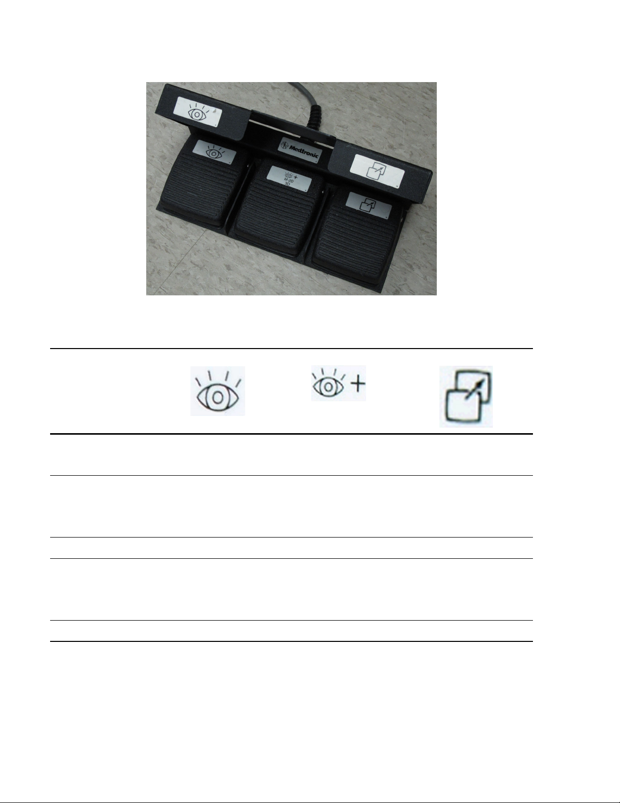
Controls and Indicators
IAS Controls and Indicators
Handswitch and Footswitch Functions
Tab l e 5 : Handswitch and footswitch functions
Acquisition Mode
2D Fluoroscopic Execute with standard
2D Multi-planar
Fluoroscopic
2D Long Film (Optional) Not available Execute* Not available
3D
*Press and hold for the duration of the acquisition. Premature release terminates the operation.
fluoroscopy
Returns to 2D fluoroscopic
mode and takes one image
at present position with
standard fluoroscopy or low
level fluoroscopy.
Returns to 2D Fluoroscopic
mode and takes one image
at present position with
standard fluoroscopy or low
level fluoroscopy.
Execute with High Level
Fluoroscopy (HLF)
Execute* Save captured images to the
Execute* Not available
Copy live image to right pane of
MVS monitor and save to
database
database
54
Page 55

MVS Components
The Mobile View Station
The Mobile View Station (MVS), shown in Figure 18, contains the monitor, keyboard, power control
panel, and an optional printer. A separate wireless mouse is included.
Controls and Indicators
MVS Components
Figure 18: MVS component locations
Number Component See
1 Video graphics printer (optional) page 56
2 Handles for transporting and
positioning the MVS
N/A
3 Keyboard page 58
4 LCD monitor (76.2 cm {30 inch}) page 57
5 X-ray activation light page 58
6 MVS power control panel page 56
7 Locking castors page 61
55
Page 56
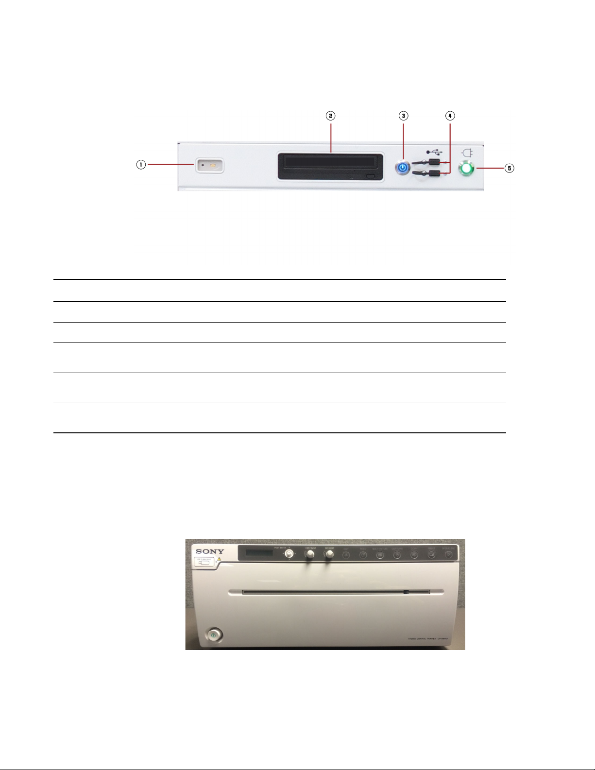
Controls and Indicators
MVS Components
The MVS Power Control Panel
Figure 19: MVS power control panel
Number Component Description
1 Wireless mouse receiver Receiver for communicating with optional wireless mouse.
2 DVD/CD RW Drive Slot for inserting CD/DVD for saving image data.
3 Power Button Press this button to turn the MVS on and off. When the system is turned on,
the button will illuminate blue.
4 USB Ports (2) USB ports for connecting external media (e.g. USB drives) for saving image
data.
5 AC Power Indicator Indicates when the MVS is plugged into an active wall outlet. When active,
this indicator will illuminate green.
Video Graphics Printer
An optional video graphics printer may be purchased with your system (Sony® UP-991AD).
Note: Do not use USB port on printer for connecting external media (e.g., USB drive); it is not used
for exporting images. Instead, use the USB drives on the MVS control panel (see Figure 19).
Figure 20: The video graphics printer
56
Use the printer to print any image appearing on the MVS monitor by turning the printer on and doing
one of the following:
Page 57
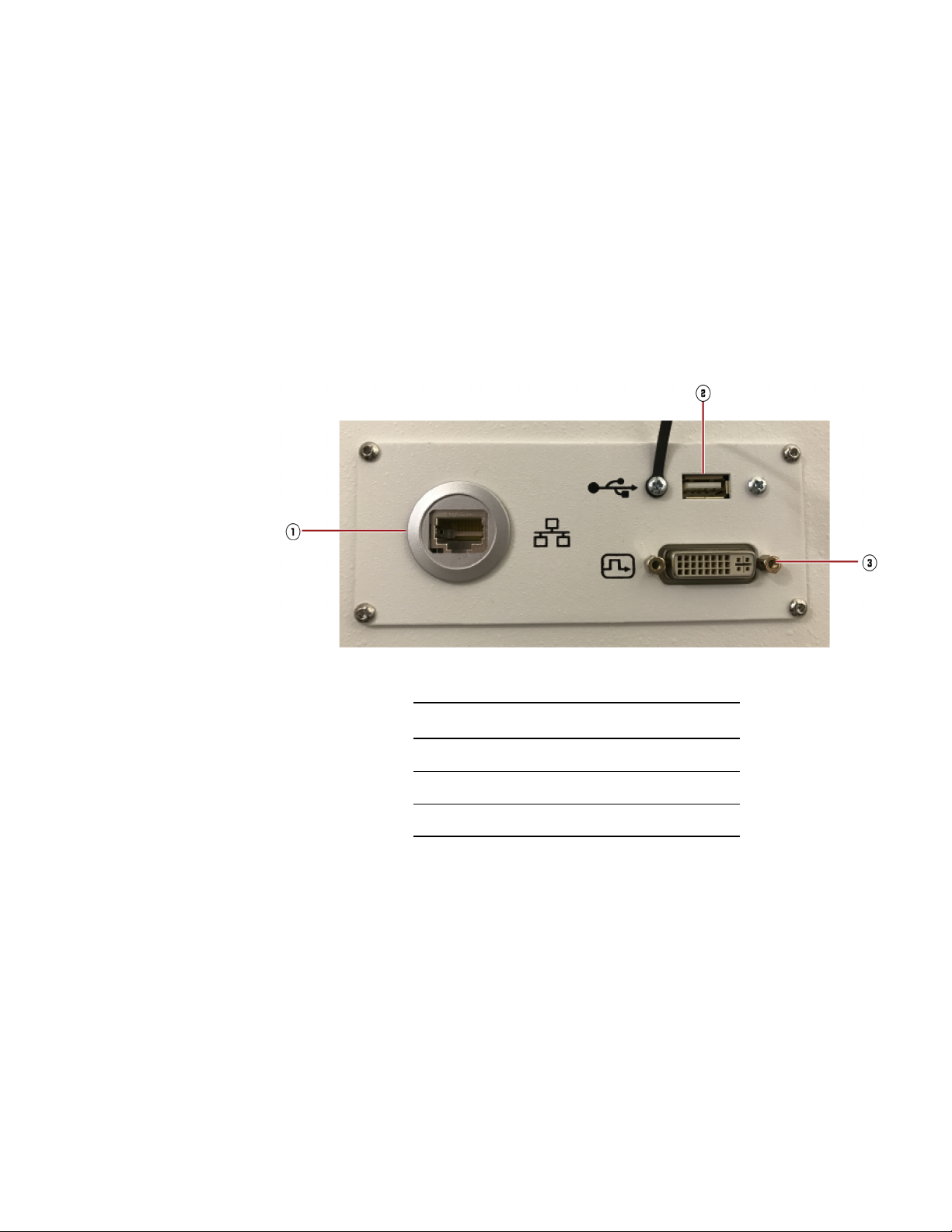
Controls and Indicators
MVS Components
• On the keyboard, press [CTRL] + [P] to send an image of the whole screen to the printer.
• On the keyboard, press [CTRL] + [Alt] + [P] to send the active viewport to the printer. This
viewport appears onscreen with a yellow border around it.
• In the software, click the [Saved Exams] tab, select the desired exam, and select the desired
image. To send the image to the printer, press [Send To...] and click [Local Printer]. For more
information on different print options, see
• On the printer, press the [Copy] button. This will reprint the most recent image that was
generated from the printer.
Printing Images to a Local Printer on page 218.
The MVS Connector Panel
Figure 21: The MVS connector panel
The Monitor
The MVS connector panel appears at the bottom rear of the MVS. 3.
Number Description
1 Connection port for ethernet cable.
2 USB port
3 DVI port for connecting a second monitor
Overview
The MVS monitor has a 76.2 cm (30 inch) flat-panel LCD display for:
• Viewing images captured by the system
• Interfacing with the patient database
• Annotating images
57
Page 58

Controls and Indicators
MVS Components
Image Display
When startup is complete, the right pane displays the patient Exam Information page. Refer to
“
Entering New Patient Data at Time of Examination” on page 99.
• In 2D mode, the left pane shows the active image and the right pane shows the reference image.
The right pane can be switched between an x-ray image and the Exam Information page
whenever the system is not in an active 2D mode.
• In M-2D mode, the monitor displays up to four separate images, taken at each of the preset
positions and conditions.
• In 3D mode, the monitor shows reconstructed images of the subject anatomy in three orthogonal
planes. The display can be toggled between default 2-and-1, a single enlarged image, and a light
box display.
Full descriptions of all three modes are in Chapter 7.
X-ray Activation Light
The activation light on the top of the monitor illuminates when any of the three imaging modes are
activated. It remains lit until the active imaging session is finished.
The Keyboard and Wireless Mouse
The Keyboard
Figure 22: The MVS keyboard
The MVS contains a US-standard QWERTY keyboard for entering text and performing functions
such as opening and closing windows.
The Touch Pad
The touch pad and two buttons, shown in Figure 23, allow you to move the cursor and make
selections on the monitor screen.
58
Page 59

Figure 23: The MVS keyboard touch pad
Controls and Indicators
MVS Components
1 Touch pad – moves the cursor.
2 Right button – toggles the display, as does the right-hand mouse button.
3 Left button – selects the active image pane (yellow highlight).
Special Keys
Special function keys allow you to perform various operating functions from the MVS. Additional
functionality of these keys is explained in the respective sections on manipulating the display in 2D
on page
159, M2D on page 166, and 3D modes on page 191.
Figure 24: The MVS special key assignments
Table 6: Descriptions of MVS special key assignments
Key /Icon Function in 2D Mode
Esc Toggles the patient Exam Information display on/off. Refer to “Entering New
Patient Data at Time of Examination” on page 99.
F1 - 2D Selects the 2D Fluoroscopy mode. For the optional 2D Long Film mode,
enter 2D Fluoroscopy mode and then press the Long Film softkey.
F2 - M-2D Selects the 2D multi-planar pulsed fluoroscopy mode.
59
Page 60

Controls and Indicators
MVS Components
Key /Icon Function in 2D Mode
F3 - 3D Selects the 3D mode.
F4 Increases edge enhancement levels.
F5 Increases brightness.
F6 Increases contrast.
F7 Flips image along the vertical plane. This feature is disabled in 3D mode
F8 Flips image along the horizontal plane. This feature is disabled in 3D mode
F9 Inverts video Image.
F10 Decreases edge enhancement levels
F11 Decreases brightness.
F12 Decreases contrast.
Insert Rotates the image clockwise. This feature is disabled in the optional 2D
Delete Rotates the image counter-clockwise. This feature is disabled in the
and in the optional 2D Long Film mode.
and in the optional 2D Long Film mode.
Long Film mode.
optional 2D Long Film mode.
60
Home Performs slice average function for 3D images.
Increases the level of noise filtering and creates a smoother 3D image.
End Performs slice average function for 3D images.
Decreases the level of noise filtering.
Page Up Viewing planes: scrolls through the images.
When displaying the 3D model (MIP view), rotates the image clockwise
around the selected axis.
Page 61

Controls and Indicators
MVS Components
Key /Icon Function in 2D Mode
Page Down Scrolls through the images
When displaying the 3D model (MIP view), rotates image counterclockwise.
Prt Sc Saves the image on the MVS screen to a .TIFF file in the MVS database.
The Wireless Mouse
A wireless mouse, shown in Figure 25, allows you to select and manipulate images on the MVS
monitor screen and serves as a laser pointer. You can order sterile wireless mice in a case of ten
(10). See “
Ordering Accessory Items” on page 11.
Figure 25: Wireless mouse
For information on mouse components and setting up the mouse for use, see “Unpacking and
Activating the Mouse” on page 96.
For information on using the mouse to manipulate the image on the MVS screen in 2D, M-2D and
3D modes, see pages
Locking Casters
The MVS is equipped with four locking casters (see Figure 26). In order to prevent lateral movement
while the MVS is in use, all four casters must be locked.
1. Position the MVS according to surgical needs.
2. Press down firmly 1 on the locking lever for each caster.
3. To unlock the caster, lift 2 each locking lever until it is horizontal.
159, 166, and 191 respectively.
61
Page 62

Controls and Indicators
MVS Components
Figure 26: MVS locking casters
62
Page 63

4 Powering Up and Configuring the
System
This chapter describes how to connect, power up, and configure the O-arm™ O2 Imaging System.
Connecting and Powering Up the System
Cable Connections
To power up the complete system (MVS and IAS), plug the MVS in a power source and then plug
the IAS into the MVS via the MVS interconnect cable. The MVS power cable and MVS interconnect
cable are located on the bottom rear of the MVS station.
Caution: Prior to operation, ensure that the equipment is thoroughly dry from any condensation that
may have formed during transport or storage.
63
Page 64

Powering Up and Configuring the System
Connecting and Powering Up the System
Figure 27: MVS power connector panel
Number Description
1 Equipotential ground point
2 Power cable for supplying power to MVS.
3 MVS Interconnect cable that supplies power to IAS.
4 Circuit breakers.
The MVS Power Cable
The MVS power cable requires a 3-wire wall outlet rated at one of the following voltages:
• 120 VAC
• 240 VAC
• 100 VAC
Confirm the voltage rating listed on the MVS product label, located where the power cord enters the
MVS.
Caution: Do not plug the O-arm™ O2 Imaging System into the same branch circuit that supplies
other devices; its maximum current rating will use most of the branch circuit's capacity.
64
The MVS Interconnect Cable
The MVS interconnect cable attaches to the IAS connector port and supplies inline voltage to it. This
cable includes a metal dust cover on the end of this cable to protect the pins (see Figure
the latch on the dust cover to remove and replace it over the end of the MVS interconnect cable.
28). Use
Page 65
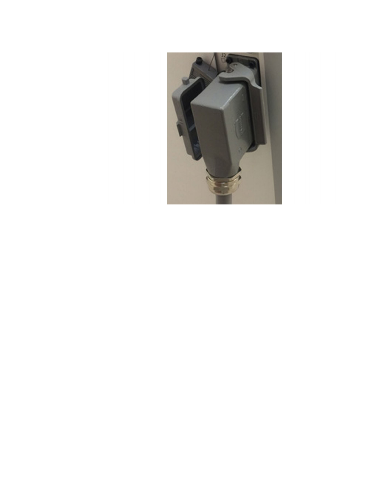
Powering Up and Configuring the System
Connecting and Powering Up the System
Figure 28: Dust cover for MVS interconnect cable
Connecting Cables
1. Position the MVS so that its power cable can reach a power outlet. Ensure the position of the
MVS does not obstruct access to the power outlet.
2. Plug the MVS power cable into the power outlet.
3. Uncoil the MVS interconnect cable and stretch it out on the floor.
4. If necessary, reposition the IAS so that the MVS interconnect cable reaches it.
5. Remove the dust cover from the end of the MVS interconnect cable, and plug the cable into the
IAS connector panel, which is located on the rear of the IAS system on the right side.
When the MVS interconnect cable is disconnected or the MVS power cable is unplugged from
the power outlet, the IAS is in standalone mode. In standalone mode, the IAS draws on its
storage batteries to perform transport and motion functions.
65
Page 66

Powering Up and Configuring the System
Connecting and Powering Up the System
Powering Up the System
Before powering up the system, make sure that the MVS and IAS are connected to each other via
the MVS interconnect cable. If you turn on the IAS before it is connected to the MVS, you’ll need to
wait at least 2 minutes before connecting it.
Once the MVS and IAS are connected, you can turn the system on. Power to the IAS is controlled
by a combination of the key switch on the connector panel, shown in Figure
on the power control panel, shown in Figure 15.
Application of power to the MVS is controlled by the power switch on the power panel.
Warning: The start procedure may be interrupted if a pendant button is actuated during the start. Do
not actuate any pendant button until the Image Acquisition System (IAS) has booted successfully.
1. On the IAS connector panel, turn the key to the enable position.
2. On the IAS power panel, press the Power button. This button illuminates blue when the IAS is
powered on.
14, and the Power button
Warning: Holding the button after it illuminates causes a “hard” shutdown on the Image
Acquisition System (IAS). Once the button illuminates blue, release the button and allow the
IAS to start completely and successfully.
3. On the MVS power panel, press the Power button to turn on the MVS power. This button
illuminates blue when the MVS is powered on.
Warning: The start procedure may be interrupted if any Mobile View Station (MVS) button is
actuated during the start. Do not actuate any MVS button until the MVS has booted
successfully.
The system takes about three minutes to boot up and run through its power on self-test. Once the
system successfully completes the self-test, it is ready for use.
If an error message appears that indicates a mismatch between the MVS and IAS software revision
numbers:
1. Press [OK]
2. Disconnect the MVS interconnect cable from the IAS connector panel.
3. Wait at least five seconds and reconnect it.
If you power up the system without receiving any error messages, proceed with normal operation. If
the mismatch error message appears again, contact Medtronic technical service desk. Refer to
“
Medtronic Technical Service” on page 10.
66
If other warning or failure messages appear on the pendant or MVS screen, contact the Medtronic
technical service desk.
Page 67

Responding to Invalid Geometry Calibration File Message
If the following message appears during system startup that requests a valid geometry calibration
file, contact Medtronic technical service for assistance. This file is required for acquiring 3D
navigated scans. If acquiring non-navigated 3D scans, press [OK] to clear the message after
contacting Medtronic, and proceed with the non-navigated 3D scan. Note that this file does not
pertain to functionality for performing the Fluoroscopic gain or RAD gain calibrations described in
Chapter 9 (see page 245).
Figure 29: Message for invalid geometry calibration file
Log in Security with User Authentication
The O-arm™ O2 Imaging System provides two optional security features for preventing unauthorized
users from logging into the system:
Powering Up and Configuring the System
Connecting and Powering Up the System
• User authentication feature that requires users to enter their own user names and passwords.
This feature may only be turned on or off by authorized Medtronic staff.
• An Auto Log Out feature that logs out a user automatically if the O-arm™ software remains idle
for a specific amount of time. This feature is turned off by default.
Configuration Support for LDAP Authentication
Note: This feature can only be enabled by Medtronic. For details, contact Medtronic technical
service.
The O-arm™ O2 Imaging System may be configured to support LDAP (Lightweight Directory Access
Protocol) authentication, which enables LDAP users to log into the O-arm
hospital network credentials. Once configured, these users are added to the system automatically if
they are authenticated to an LDAP directory service provider. Their user authentication settings
cannot be viewed or modified, but may be deleted from the O-arm
staff.
LDAP users appear in the list of authorized users with an asterisk(*). To view this list, press the
Authorized Users tab on the System Technical Service Console.
™
system with their
™
system by authorized hospital
Logging In and Logging Out of the System
1. To log into the system, enter your user name and password in the User Log In panel:
67
Page 68
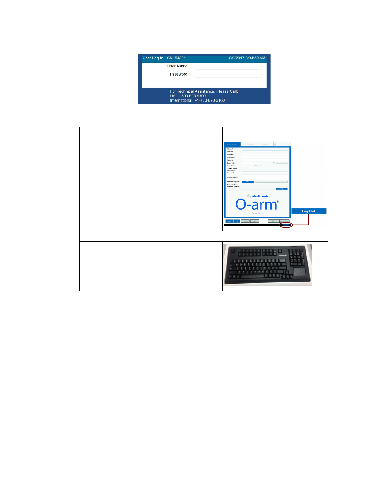
Powering Up and Configuring the System
Connecting and Powering Up the System
2. To log out of the system:
Press [Log Out] at the bottom right of the MVS screen;
Figure 30: User Log in panel
Action Image
- or -
Press the [ALT] + [L] keys simultaneously.
About the Auto Log Out Feature
Note: This feature is disabled by default. To turn on this feature, see “Turning On the Auto Log Out
Feature” on page 72.
If this feature is turned on, you will be logged out automatically if the software remains idle for a
specific duration of time. Prior to the log out, a message panel appears that displays a 30 second
countdown timer (see Figure
• To cancel the log out and continue working, press [Cancel].
• To proceed with the log out, press [Log Out].
31, 1):
68
Page 69
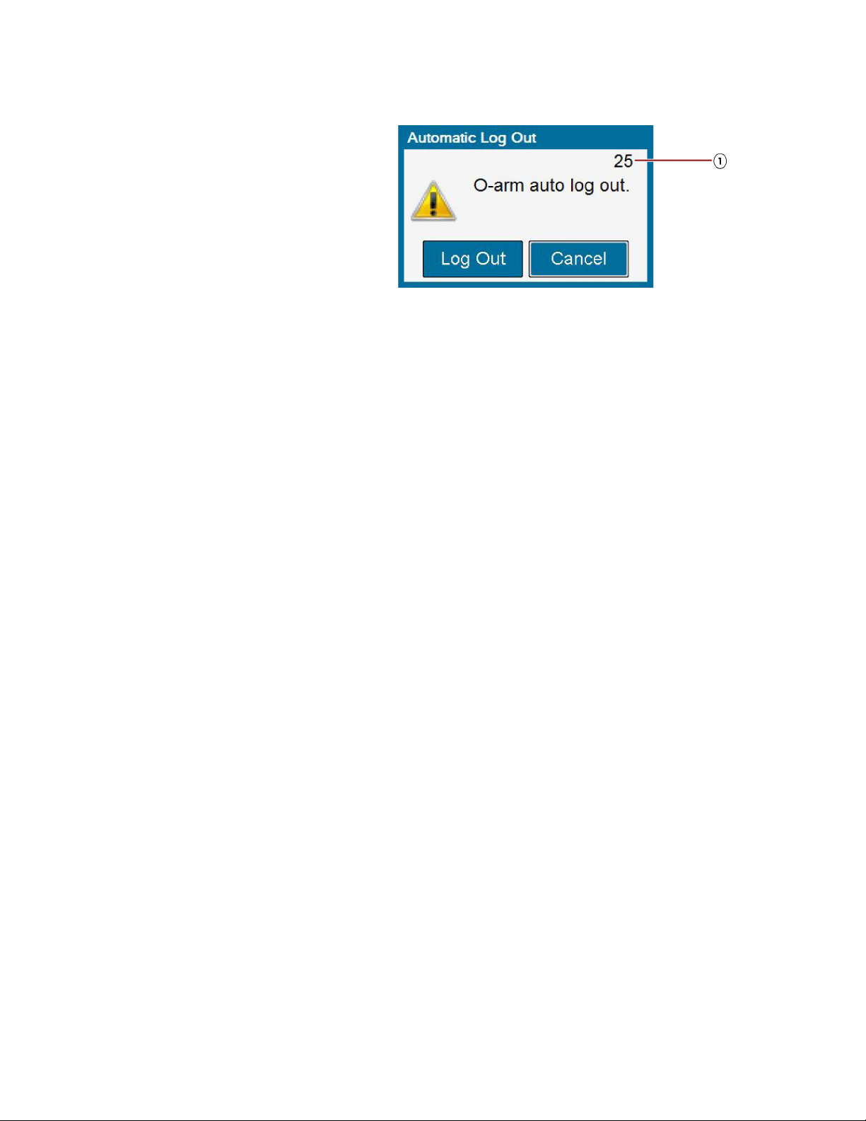
Figure 31: Auto Log Out message panel
Changing User Authentication Settings
Authorized hospital staff may change the following user authentication settings:
• Add, modify, and delete settings for authorized users who can access the O-arm™ system (see
pages
70 to 71). Note that you cannot modify or view authentication settings for LDAP users.
• Turn on and off the Auto Log Out feature (see page 72), Note that this feature is turned off by
default.
Powering Up and Configuring the System
Connecting and Powering Up the System
To change these settings, access the Authorized Users tab:
1. Open the System Technical Service Console. To open, press the [Ctrl] [Alt] [Home] keys on
the keyboard simultaneously and enter the user name and password.
2. Click the Authorized Users tab (Figure 32, 1).
69
Page 70
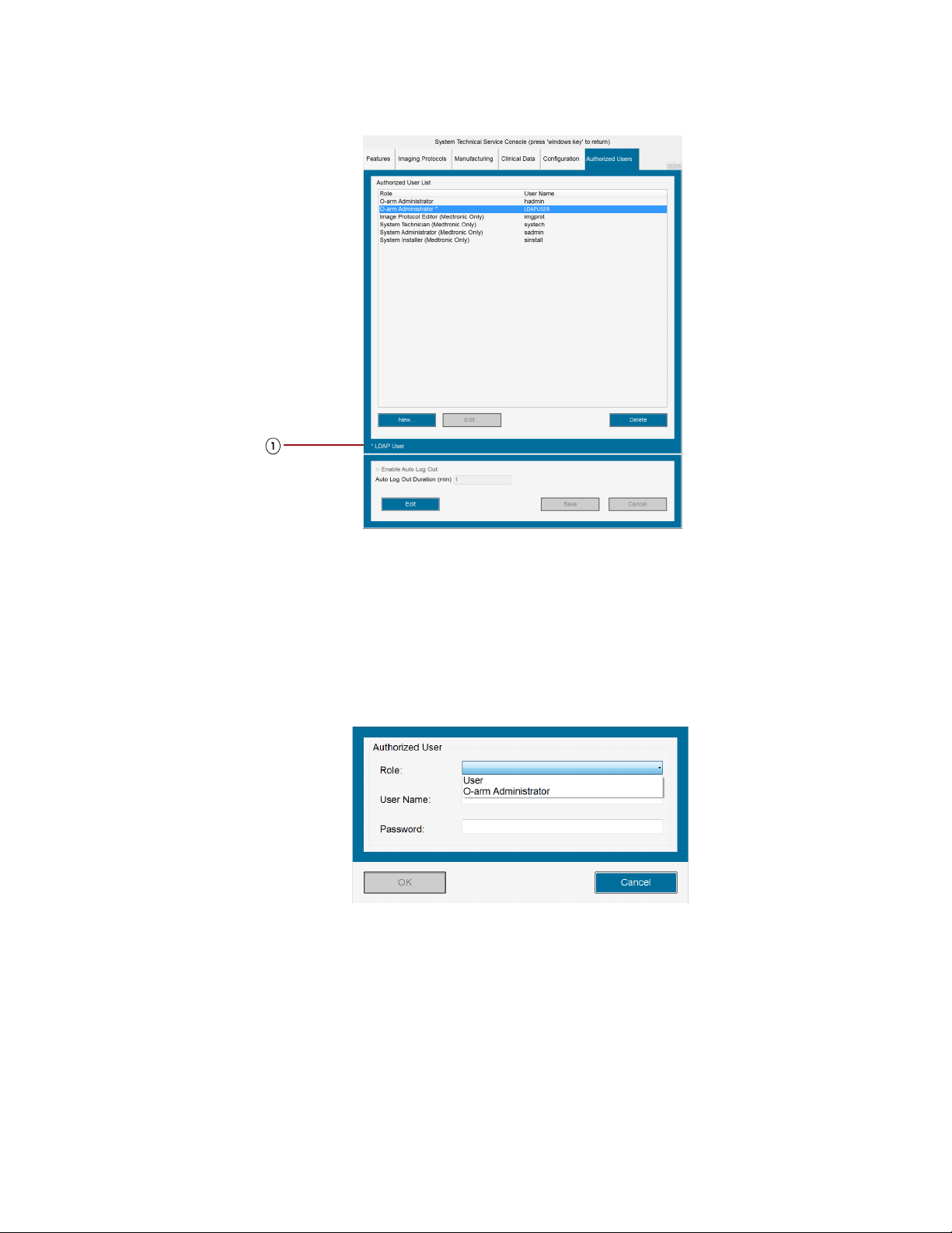
Powering Up and Configuring the System
Connecting and Powering Up the System
Figure 32: Authorized Users tab for changing user authentication settings
Adding Authorized Users
Only authorized hospital staff may change user authentication settings.
1. On the System Technical Service Console, click the Authorized Users tab (see Figure 32,
1).
2. Press [New]; the Authorized User panel appears:
Figure 33: Authorized User panel
3. Enter the following information:
– Role (O-arm Administrator)
– User name
– Password
70
The user name and password combination must be unique from other users.
4. Press [OK] to save the new user settings.
Page 71
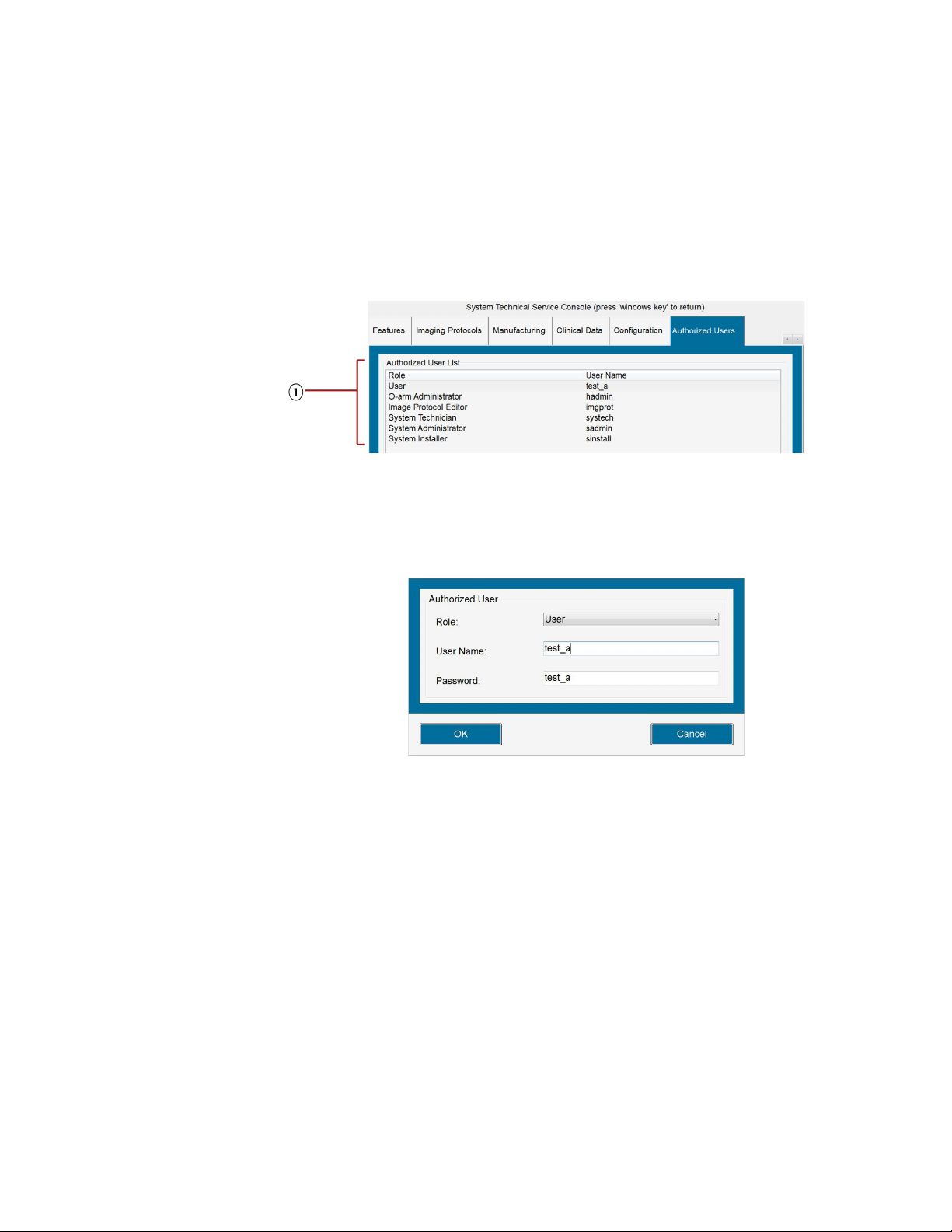
Powering Up and Configuring the System
Connecting and Powering Up the System
Modifying Authorized Users
Only authorized hospital staff may change user authentication settings.
1. On the System Technical Service Console, click the Authorized Users tab (see Figure 32,
1).
2. In the Authorized Users List section of the tab (Figure 34, 1), select the user whose settings
you want to modify;
Figure 34: Authorized User List for modifying user settings
Note: You cannot modify authentication settings for LDAP users. For these user types, the [Edit]
button is disabled. For details on LDAP, see “Configuration Support for LDAP Authentication”
on page 67.
3. Press [Edit]; the Authorized User panel appears for that user.
Figure 35: Sample user settings on Authorized User panel
4. Modify the new user settings and press [OK] to save those settings. Note that each user name
and password combination must be unique from other users.
Deleting Authorized Users
Only authorized hospital staff may change user authentication settings.
1. On the System Technical Service Console, click the Authorized Users tab (see Figure 32,
1).
2. In the Authorized Users List section of the tab (Figure 36, 1), select the user you want to
remove.
71
Page 72
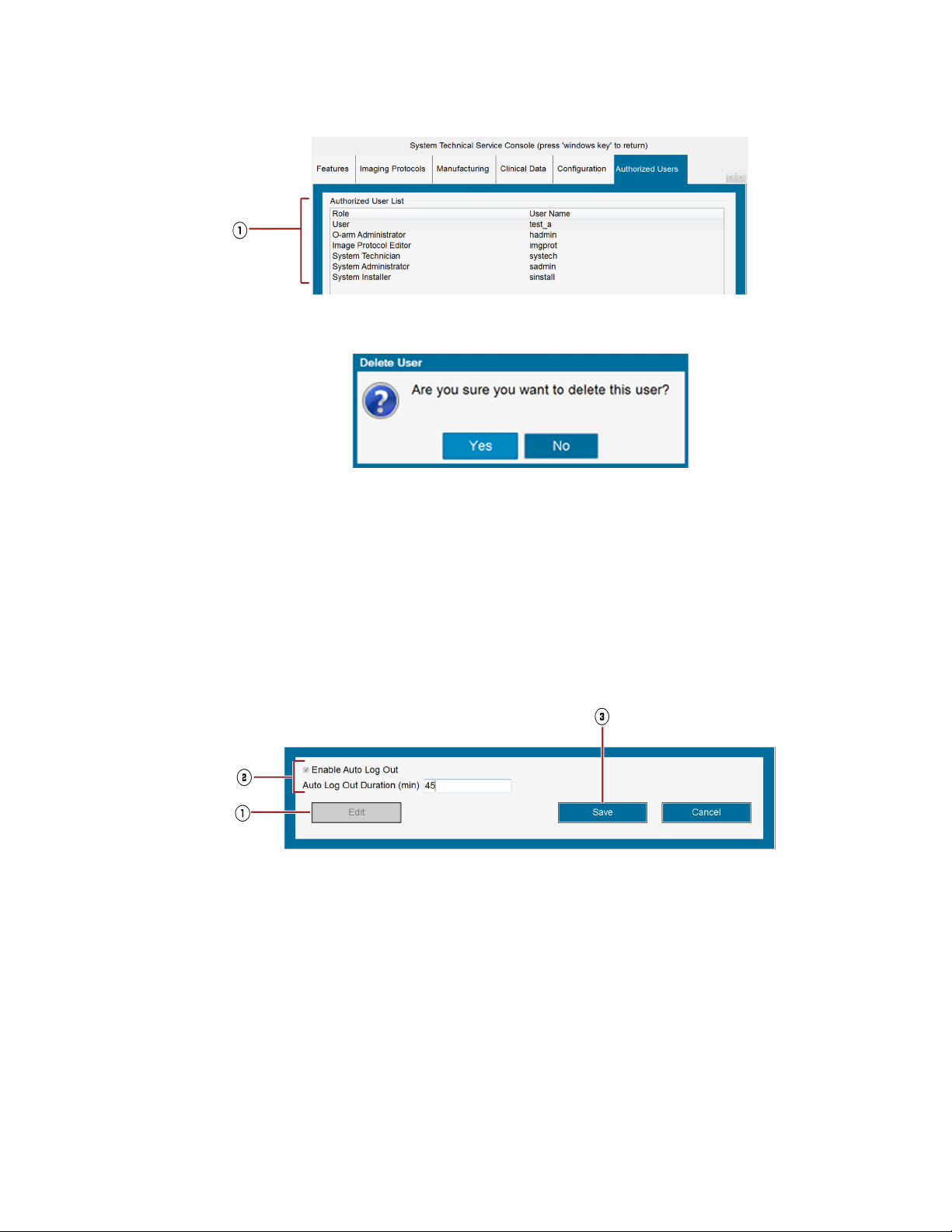
Powering Up and Configuring the System
Connecting and Powering Up the System
3. Press [Delete]; the following confirmation panel appears:
4. Press [Yes] to confirm the deletion.
Figure 36: Authorized User List for deleting authorized users
Figure 37: Confirmation panel for deleting authorized user
Turning On the Auto Log Out Feature
Only authorized hospital staff can turn on and off the Auto Log Out feature.
1. On the System Technical Service Console, click the Authorized Users tab (see Figure 32,
1).
2. In the Auto Log Out section of the tab, press [Edit] (Figure 38, 1) to enable the options for
changing the Auto Log Out settings.
Figure 38: Auto Log Out panel on Authorized Users tab
3. Select [Enable Auto Log Out] (Figure 38, 2) to turn it on.
4. In the Auto Log Out duration (min) field (Figure 38, 2), enter the number of minutes
(between 1 and 480) that the O-arm software can remain idle before logging out of the system
automatically.
5. Press [Save] (Figure 38, 3); the changes will be applied after restarting the application.
72
Page 73

Powering Up and Configuring the System
Configuring the System with the Technical Service Console
Configuring the System with the Technical Service
Console
Configuration Overview
The system should be configured before first-time use. Your service technician may perform these
steps, but information is provided here in case you need to make any changes.
All configuration steps are performed through the System Technical Service Console. This page
requires a user name and password. See your system administrator for details.
Configuration Step See
Setting the interface language page 75
Setting measurement units for patient information page 76
Entering the date, time, time zone, and daylight savings page 77
Adding Physicians to the Physicians List page 88
Configuring DICOM server connections:
• The Worklist Server Connection
• The IGS Server Connection (if the O-arm
used with an IGS system)
• The DICOM Store Server
Calibrating the monitor display page 90
™
O2 Imaging System will be
page 78
• page 80
• page 82
• page 87
Opening the System Technical Service Console
1. Press [Ctrl] [Alt] [Home] on the keyboard to open the user access popup.
2. Type in your user name and password and press [Enter]; the System Technical Service
Console appears (see Figure
39).
Hiding and Logging Out of the System Technical Service Console
• To hide the System Technical Service Console, press the [Windows®] key .
• To log out of the System Technical Service Console, press [Log Out] at the bottom of the
screen or type [Alt] + [L] keys on the keyboard simultaneously.
About the System Technical Service Console
The System Technical Service Console provides a set of panels for configuring, maintaining, and
troubleshooting the O-arm
console are intended only for authorized Medtronic Navigation staff.
™
O2 Imaging System. Please note that many of the panels on this
73
Page 74

Powering Up and Configuring the System
Configuring the System with the Technical Service Console
Figure 39: System Technical Service Console
™
Note: If the O-arm
O2 Imaging System has the optional 2D Long Film mode, the Run Rad Gain
Calibration button on the Maintenance tab appears as Run 3D/2D Long Film RAD Gain
Calibration.
For a description of each tab, see Table 7.
Tab l e 7 : Description of tabs on Technical Service Console
Tab Description
Maintenance Provides calibration tools for maintaining the O-arm
™
O2 Imaging System.
MVS Station Provides tools for configuring the time, date, name, and IP address of the MVS station.
UI Specifies the language and units of measurements that appear on the O-arm
™
Imaging System screens.
DICOM Servers Provides tools for configuring the O-arm
™
O2 Imaging System to work list servers,
image guided system servers, and DICOM Store servers.
Physicians Stores the names of each physician who uses the O-arm
System Information Specifies the versions of hardware, firmware, and software used in the O-arm
™
O2 Imaging System.
™
Imaging System. This tab is intended only for authorized Medtronic staff.
Logs Records audit logging data for troubleshooting technical problems.
O2
O2
74
Page 75

Powering Up and Configuring the System
Configuring the System with the Technical Service Console
Tab Description
DICOM Export Specifies the voxel size and slice thickness parameters for the Coronal and Sagittal
DICOM images.
Features Lists the configuration status for different imaging modes and features. This tab is
intended only for authorized Medtronic staff.
Imaging Protocols Specifies the default acquisition, reconstruction and visualization parameters for each of
imaging protocols. This tab is intended only for authorized Medtronic staff.
Authorized Users Controls the list of authorized users who can access the O-arm
settings to specify the duration of time for the auto logout feature.
Configuring Interface Language and Units
User Interface Language
The UI tab in the System Technical Service Console provides access to a drop-down list for selecting
the user interface (UI) language. Available languages include:
• English
• German
• French
• Italian
• Spanish
• Dutch
• Russian
™
system. Also provides
1. On the System Technical Service Console, click the UI tab.
75
Page 76

Powering Up and Configuring the System
Configuring the System with the Technical Service Console
Figure 40: Interface language selection
76
2. On the [UI] tab, click [Edit].
3. Use the drop-down list to select the language.
4. Click [Save].
5. Cycle system power to save the language setting.
Patient Information Measurement Units
Values for patient height and weight may be displayed in standard or metric units. The default units
are standard. To change the displayed units to metric, check the Display Patient Info in Metric
Units checkbox.
Configuring Date and Time
Date and Time Formats
Date and Time formats shown in patient data displays follow those selected under the UI tab in the
System Technical Service Console.
Page 77

Powering Up and Configuring the System
Configuring the System with the Technical Service Console
How to Configure Date and Time Settings
1. On the System Technical Service Console, click on the MVS Station tab.
2. On the [MVS station] tab, click [Edit].
3. Use the drop-down calendar under Date and Time Settings to select the date.
Figure 41: Selecting the date
4. In the Date and Time Settings field:
– Select the hour and enter the hour
– Select the minutes and enter the minutes
– Select AM/PM and enter AM or PM.
5. Use the Time Zone drop-down list to select the desired zone.
6. Check the box to automatically adjust the clock for daylight saving changes.
7. Click [Save] to save your changes.
77
Page 78

Powering Up and Configuring the System
Setting Up DICOM Export Configurations
Setting Up DICOM Export Configurations
Connecting to the Network
Before configuring the MVS to export images to a DICOM server, the MVS must be physically
connected to the hospital’s DICOM network, and the MVS must be identified by a station name.
Figure 42: MVS connector panel with ethernet jack
Connecting the Network Cable
1. Connect one end of the network cable to the ethernet jack on the MVS connector panel.
2. Connect the opposite end of the network cable to the hospital’s ethernet wall jack.
3. Ensure that both connectors are locked in place.
Assigning the MVS a Station Name
To export images from the O-arm™ O2 Imaging System to a DICOM server, the MVS must be
assigned a station name so that it is recognized on your hospital network.
1. Open the System Technical Service Console (see page 73).
2. Click on the MVS Station tab.
78
Page 79

Powering Up and Configuring the System
Setting Up DICOM Export Configurations
Figure 43: MVS Station configuration
3. Click [Edit]. This allows you to fill in the text boxes.
4. In the Hospital Name field, type the name of the hospital.
5. In the Station Name box, type the name of the workstation assigned to this MVS.
6. In the DICOM AE Title field, type the title assigned to this MVS.
7. Click [Save].
8. Cycle system power to save the Hospital Name setting.
Configuring a Worklist Server
About Worklist Servers
In order to access patient information residing on databases external to the O-arm™ O2 Imaging
System, as is discussed in the section “
104, you must configure the O-arm™ O2 Imaging System so that it is connected to a server on the
hospital network, known as a worklist server.
Acquiring Patient Information from Outside Sources” on page
79
Page 80
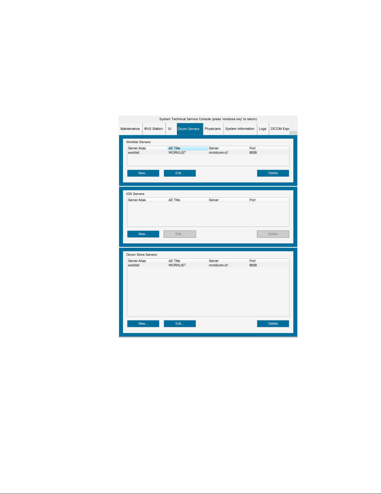
Powering Up and Configuring the System
Setting Up DICOM Export Configurations
How To Configure the Worklist Server Connection
1. Ensure that an Ethernet connection exists to the MVS connector panel. See “Connecting the
Network Cable” on page 78.
2. Open the System Technical Service Console, as discussed on page 73.
3. Click on the DICOM Servers tab.
Figure 44: DICOM Servers page
80
4. On the DICOM Servers page, under “Worklist Servers,” click [New]. This opens the Worklist
Server configuration dialog, shown in Figure
45.
Page 81

Powering Up and Configuring the System
Setting Up DICOM Export Configurations
Figure 45: Worklist Server configuration dialog
5. Fill in the Worklist Server configuration dialog as follows:
Server Alias: A unique name that you assign to identify the Worklist Server
AE Title: The Worklist Application Entity (AE) title
Server: The IP address or DNS Name (Host Name) assigned to the Worklist Server
Port: The number of the port assigned to the Worklist Server
Obtain any necessary information from your network administrator to complete this step.
6. Click [Verify] to confirm that you entered the information correctly and to verify the connection
between the O-arm
the entries, make the necessary corrections, and reverify the connection.
You can cancel out of the Worklist Server configuration dialog at any time by clicking [Cancel].
7. Click [OK] to save the information and return to the System Technical Service Console.
™
O2 Imaging System and the server. If an error message appears, review
Editing a Worklist Server Configuration
1. To edit an existing Worklist Server configuration, select the subject server listed under “Worklist
Servers” and click [Edit].
2. Make the desired changes to the entries in the Worklist Server configuration dialog.
3. Click [Verify] to verify the connection between the O-arm™ O2 Imaging System and the server.
4. Click [OK].
Deleting a Worklist Server Configuration
To delete an existing Worklist Server from the list, select the subject server listed under “Worklist
Servers” and click [Delete].
81
Page 82
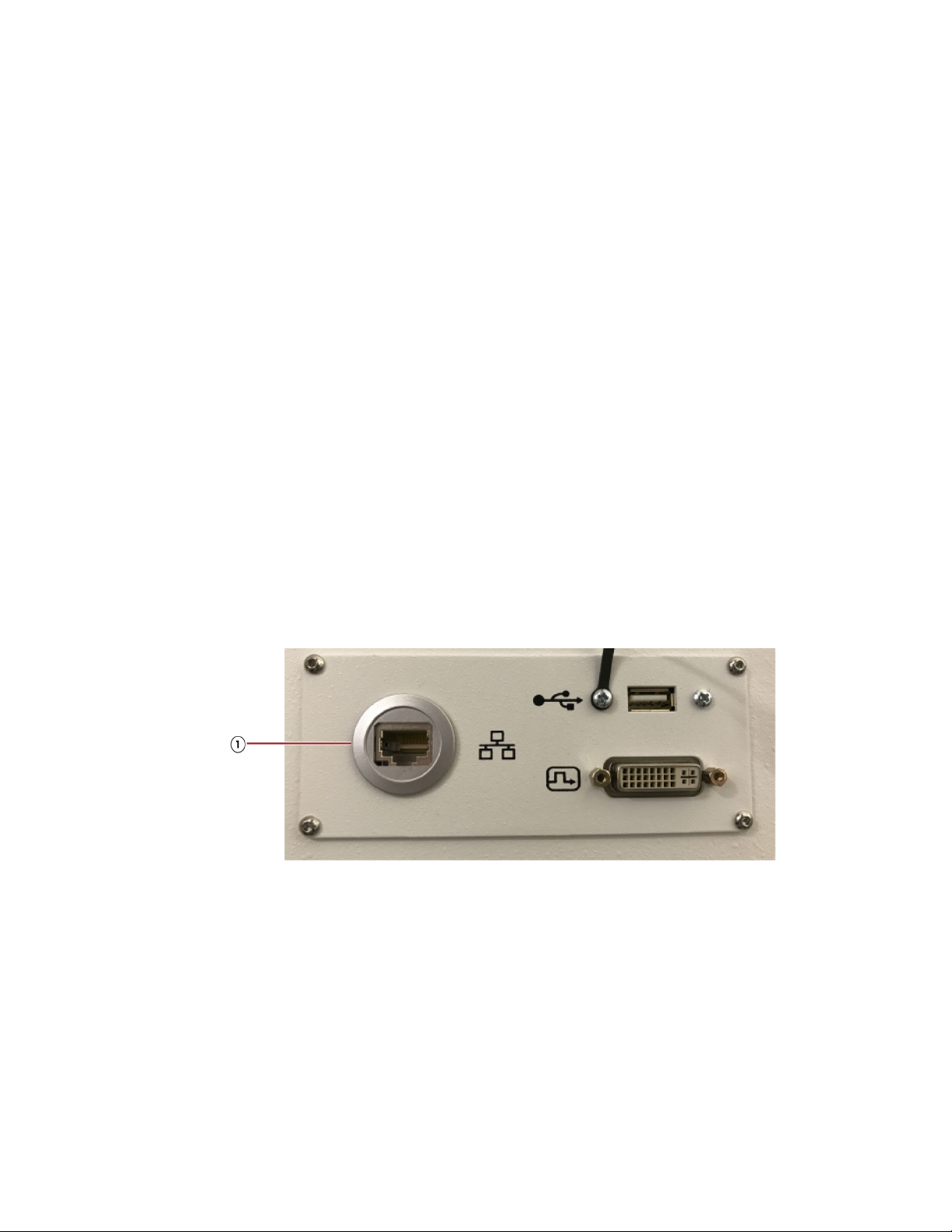
Powering Up and Configuring the System
Setting Up DICOM Export Configurations
Connecting and Configuring an Image Guided Surgery (IGS) System
Supported IGS Systems
The O-arm™ O2 Imaging System supports the following IGS systems: Medtronic StealthStation
i7™and the Medtronic StealthStation S7™ and later. For instructions on using these IGS systems
during navigation, refer to their respective user documentation. If you need to connect to one or more
IGS systems that has been configured to receive images from the O-arm
“
Selecting an IGS, StealthStation™ System, or Navigation Server from a Shared Network” on page
85.
About the IGS System Connection
To use the O-arm™ O2 Imaging System with the respective StealthStation™ system, you must:
• Connect the systems together using a standard network cable or a crossover cable, as is shown
below.
• Configure the O-arm™ O2 Imaging System so that it can communicate with the StealthStation™
System. The two steps needed to do that are described below.
™
O2 Imaging System, see
Connecting the Network Cable
1. Connect one end of a network cable or crossover cable to the network jack 1on the MVS
connector panel.
2. Connect the other end of the cable to the StealthStation™ System network jack.
Figure 46: MVS ethernet jack
Configuring the IGS System Connection
The configuration steps to establish communication between the O-arm™ O2 Imaging System and
any StealthStation
™
system are:
82
• Assign the O-arm™ O2 Imaging System a network identity (IP Address, etc.).
• Enter the network identity of the StealthStation™ System into the MVS.
Configuration is performed through the System Technical Service Console. Access requires a
user name and password.
Page 83
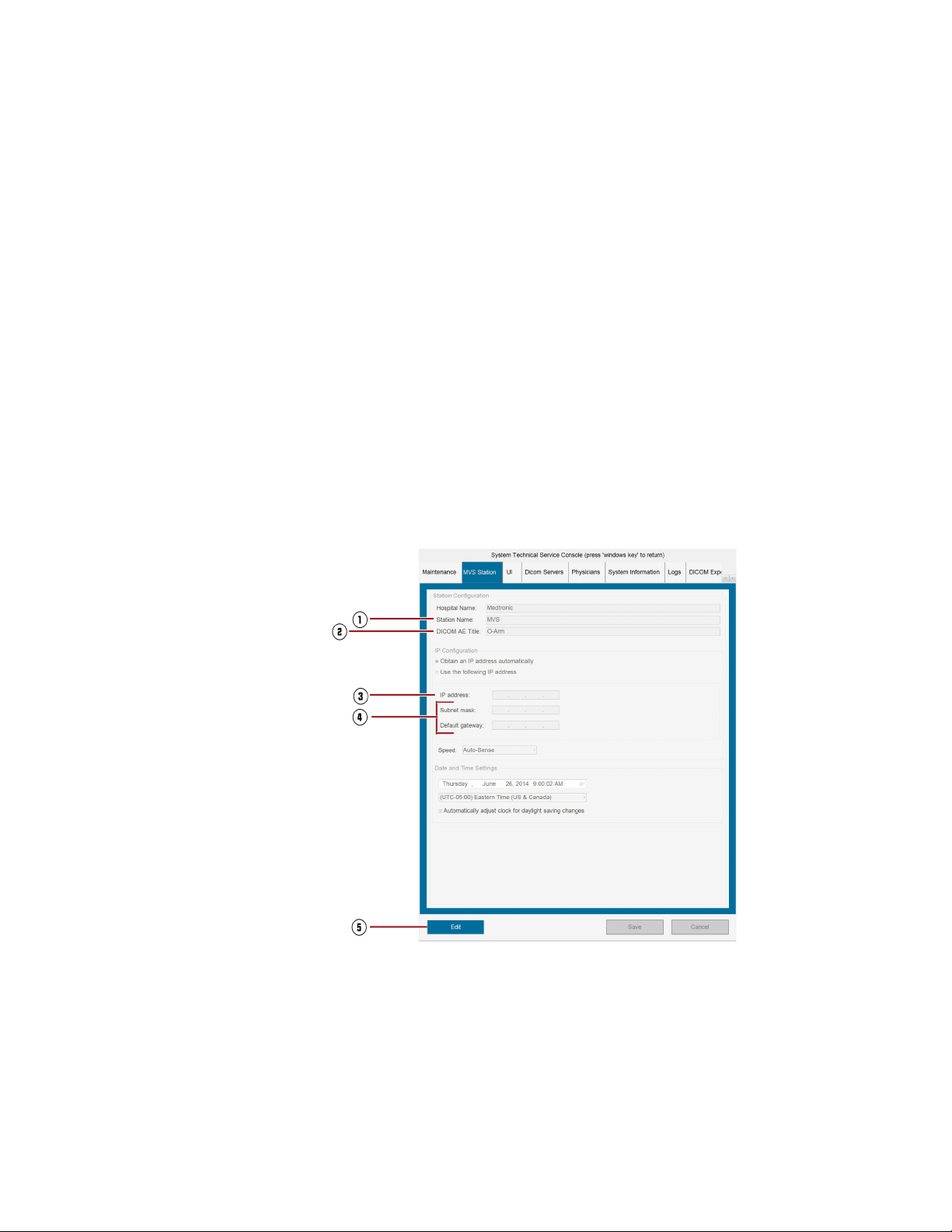
Powering Up and Configuring the System
Setting Up DICOM Export Configurations
Assigning a Network Identity to the MVS
To export images from the O-arm™ O2 Imaging System, an identity must be set on the MVS so that
other systems can recognize it and receive data from it. This step is usually performed by the
Medtronic Service Technician during installation of the O-arm
To verify that the identity has been set, click on the MVS Station tab in the System Technical
Service Console and review the information (see Figure
(2), and an IP Address (3) must be set.
• Station Name: A unique name assigned to the MVS.
• DICOM AE Title: The DICOM Application Entity (AE) title assigned to the MVS.
• IP Address: The IP address assigned to the MVS.
If this information is not displayed on the MVS Station tab page, enter it at this time. Click [Edit] (5)
to fill out the fields.
Caution: To ensure proper networking configuration, verify that subnet mask and default gateway
(
4) information on the MVS matches the subnet mask and default gateway information on the
StealthStation
long as they match.
™
. These information fields may either be blank or specify the same IP address, as
Figure 47: Setting the O-arm
™
O2 Imaging System.
47). A Station Name (1), DICOM AE Title
™
network identity
Entering the StealthStation™ Identity into the MVS
Tell the MVS where to send images that it collects by entering the StealthStation™ System
information.
1. On the System Technical Service Console, click the DICOM Servers tab (see Figure 48).
2. Under IGS Servers, click [New] (see Figure 48,1).
3. Fill in the information about the StealthStation™ System.
83
Page 84
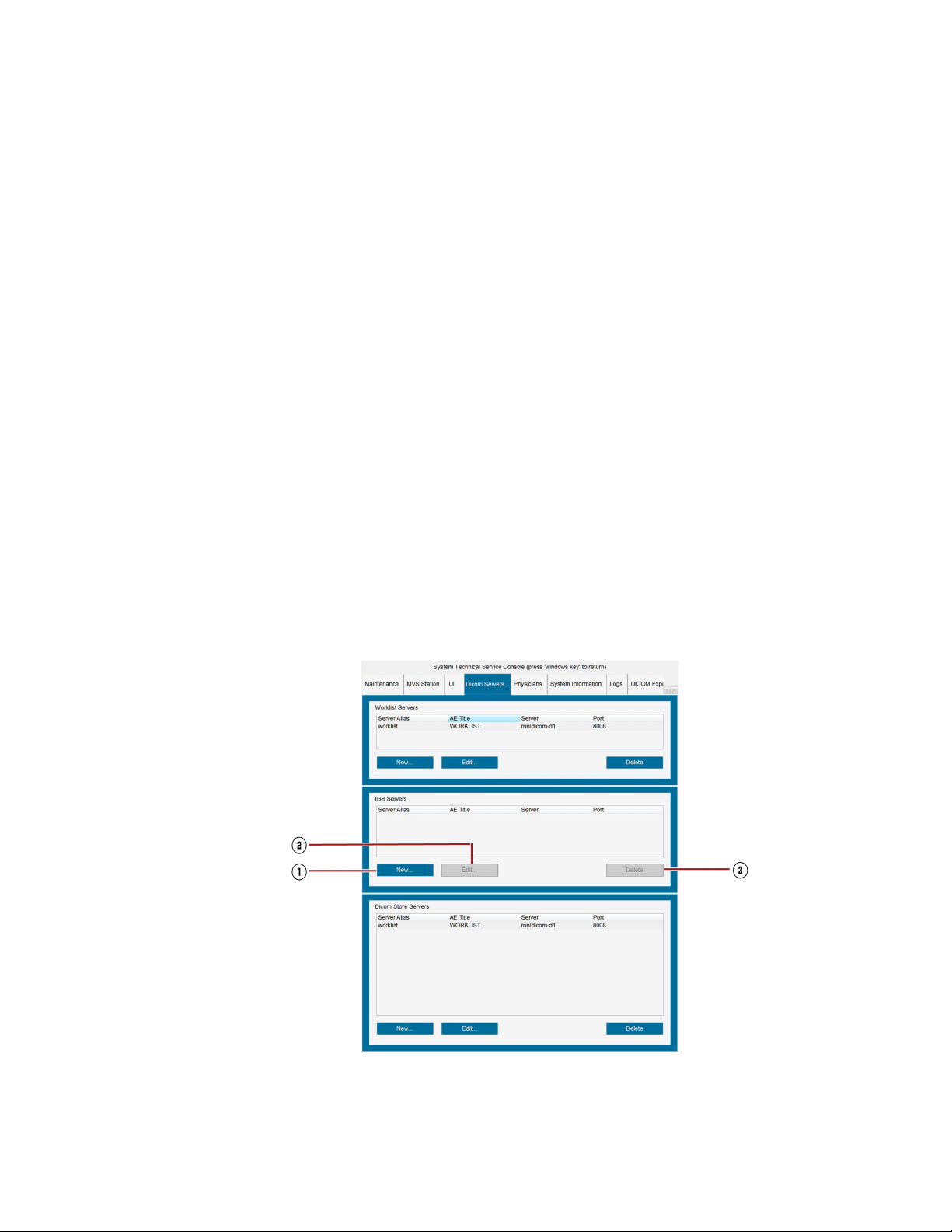
Powering Up and Configuring the System
Setting Up DICOM Export Configurations
– Server Alias: A unique name you assign to identify the StealthStation™ System
– AE Title: The StealthStation™ System Application Entity (AE) title
– Server: The IP Address assigned to the StealthStation™ System
– Port: The number of the port assigned to the StealthStation™ System
4. Click [Verify] to check the connection.
If an error message appears, review the entries, make any necessary corrections, and reverify
the connection. If the error is not resolved, check the cable connection.
5. Click [OK] to save the information.
If you do not want to save your entries, cancel out of the dialog by clicking [Cancel].
Checking or Editing an Existing Configuration
1. To check or edit an existing StealthStation™ System configuration, select the system name
listed under IGS Servers and click [Edit] (see Figure
2. Make any desired changes.
3. Click [Verify] to confirm the connection.
48, 2).
4. Click [OK] to save the changes.
Deleting an Existing Configuration
To delete the StealthStation™ System from the list, select the system name under IGS Servers, and
then click [Delete] (see Figure
Figure 48: Fields for entering StealthStation™ network identity
48, 3).
84
Page 85
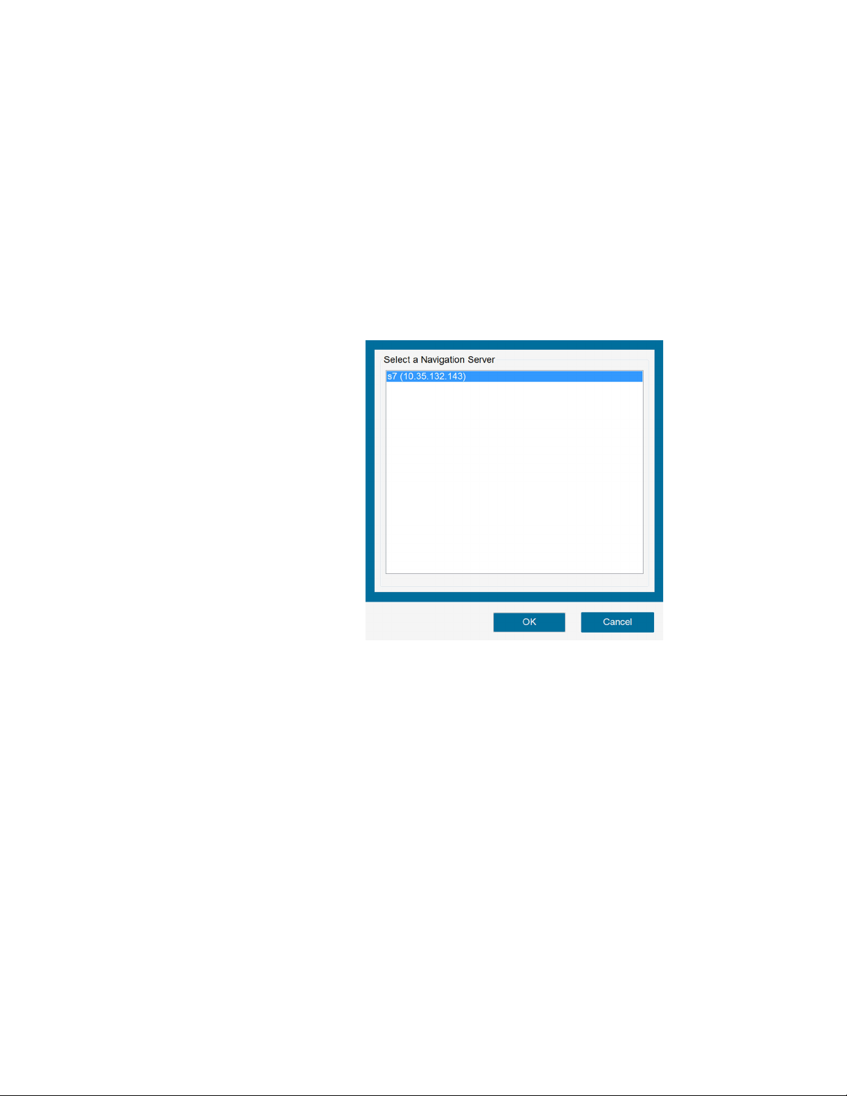
Powering Up and Configuring the System
Setting Up DICOM Export Configurations
Selecting an IGS, StealthStation™ System, or Navigation Server from a Shared Network
If you have the iOR (integrated Operating Room) feature enabled, perform the following steps to
connect to an IGS, StealthStation
is configured to receive images from the O-arm
1. Connect the O-arm™ O2 Imaging System to the appropriate IGS, StealthStation™ system.or
navigation server. For instructions, see page
2. If the Select a Navigation Server panel appears, select the name of the appropriate IGS,
StealthStation
™
system, or navigation server and press [OK] to connect to it.
™
system, or navigation server that is available on the network and
Figure 49: Select a Navigation Server panel
™
system:
82.
3. Prior to acquiring a scan, perform the following steps to verify the two systems are connected
properly:
a. On the pendant, verify that the camera icon appears with a green check mark (see 1 in
Figure 50.
b. Press the [Esc] key to open the Exam Information page and locate the Navigation
Connection field (see
c. Verify that the Navigation Connection field displays the appropriate IGS, StealthStation
navigation server.
1 in Figure 51).
™
or
85
Page 86
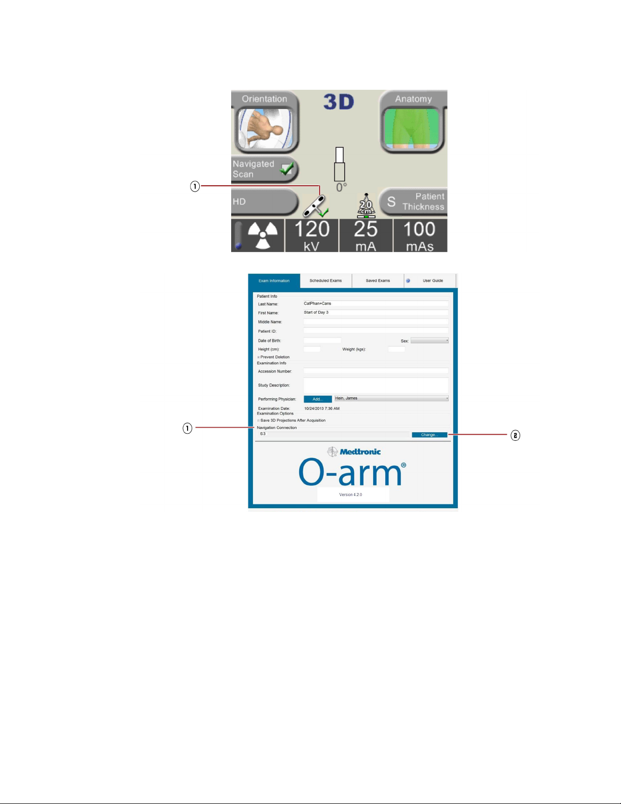
Powering Up and Configuring the System
Setting Up DICOM Export Configurations
Figure 50: Camera icon on pendant
Figure 51: Navigation Connection field
86
4. If you need to select a new StealthStation™ system or navigation server, press the [Change]
button next to the Navigation Connection field (see
2 in Figure 51) to display the Select a
Navigation Server panel.
5. Select the desired StealthStation™ system or navigation server from the list and press the [OK]
button to connect to it. Note that this panel only lists StealthStation
™
systems or navigation
servers that meet the following conditions:
– It’s configured as a navigation server in the System Technical Service Console to receive
images from O-arm
™
Imaging System.
– It’s currently powered on.
– It’s currently available on the network.
– The StealthStation™ system software is currently setup to receive images from the O-arm™
O2 Imaging System.
If the desired StealthStation™ system or navigation server does not appear in this list, refer to
page
82 for proper configuration instructions.
Page 87
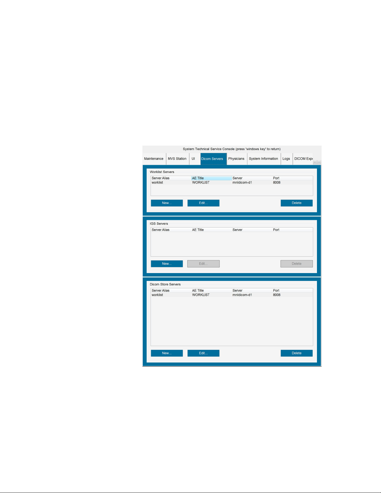
Configuring the DICOM Store Server
Prior to exporting O-arm™ images, configure the MVS so that it is connected to the DICOM store
server to which you want to export the images.
Note: The term “store server” identifies a type of network storage device used to archive images in
DICOM format.
How to Configure a DICOM Store Server
1. Click on the DICOM Servers tab to open the DICOM Server page, as shown in Figure 52.
Figure 52: DICOM server page
Powering Up and Configuring the System
Setting Up DICOM Export Configurations
2. Under Dicom Store Servers, click [New]. This opens the DICOM Server dialog.
3. Fill in the fields as follows:
– Server Alias: A unique name that you assign to the MVS that it will use to identify the DICOM
Store Server
– AE Title: The DICOM Application Entity (AE) title
– Server: The IP address assigned to the DICOM Store Server
– Port: The number of the port assigned to the DICOM Store Server
87
Page 88

Powering Up and Configuring the System
Setting Up DICOM Export Configurations
– Modality: There are two types of fluoroscopy image modality supported by the MVS
◦ XA, which is the X-ray Angiographic, is the default.
◦ RF, which is the Radio Fluoroscopic.
– Bits Stored: The word size of the stored image. Twelve BITS is the default for all images.
– Structured Reports Sent: Check the Radiation Dose checkbox if the server is capable of
accepting structured dose reports. If checked, this server is displayed in the Send To dialog
for DICOM server selections.
4. Click [Verify] to ensure that the information is entered correctly and to confirm the connection
between the MVS and the server. If an error message appears, review the entries, make the
necessary corrections, and reverify the connection.
5. Click [OK] to save the information and return to the System Technical Service Console.
Note: To close the dialog without saving, click [Cancel].
Editing an Existing DICOM Server Configuration
1. On the DICOM Servers page, click on the server’s name under Dicom Store Servers, shown in
Figure
44 on page 80, and then click [Edit].
2. Make any desired changes.
3. Click [Verify] to ensure that the information is entered correctly and to confirm the connection
between the MVS and the server.
4. Click [OK] to save the information and return to the System Technical Service Console.
Removing a DICOM Server from the List
To delete a DICOM Server from the list, click on the subject server listed under Dicom Store Servers
and click [Delete].
When you are finished with all changes, press the [Windows®] key to exit the System
Technical Service Console.
Adding To and Modifying the Physicians List
Accessing the Physicians List
1. Open the System Technical Service Console.
a. Press [Ctrl] [Alt] [Home] on the keyboard to bring up the user access popup.
b. Type in your user name and password and press [Enter]. The System Technical Service
Console opens.
88
2. Click on the Physicians tab. The Physicians List, as shown in Figure 53, opens.
Page 89
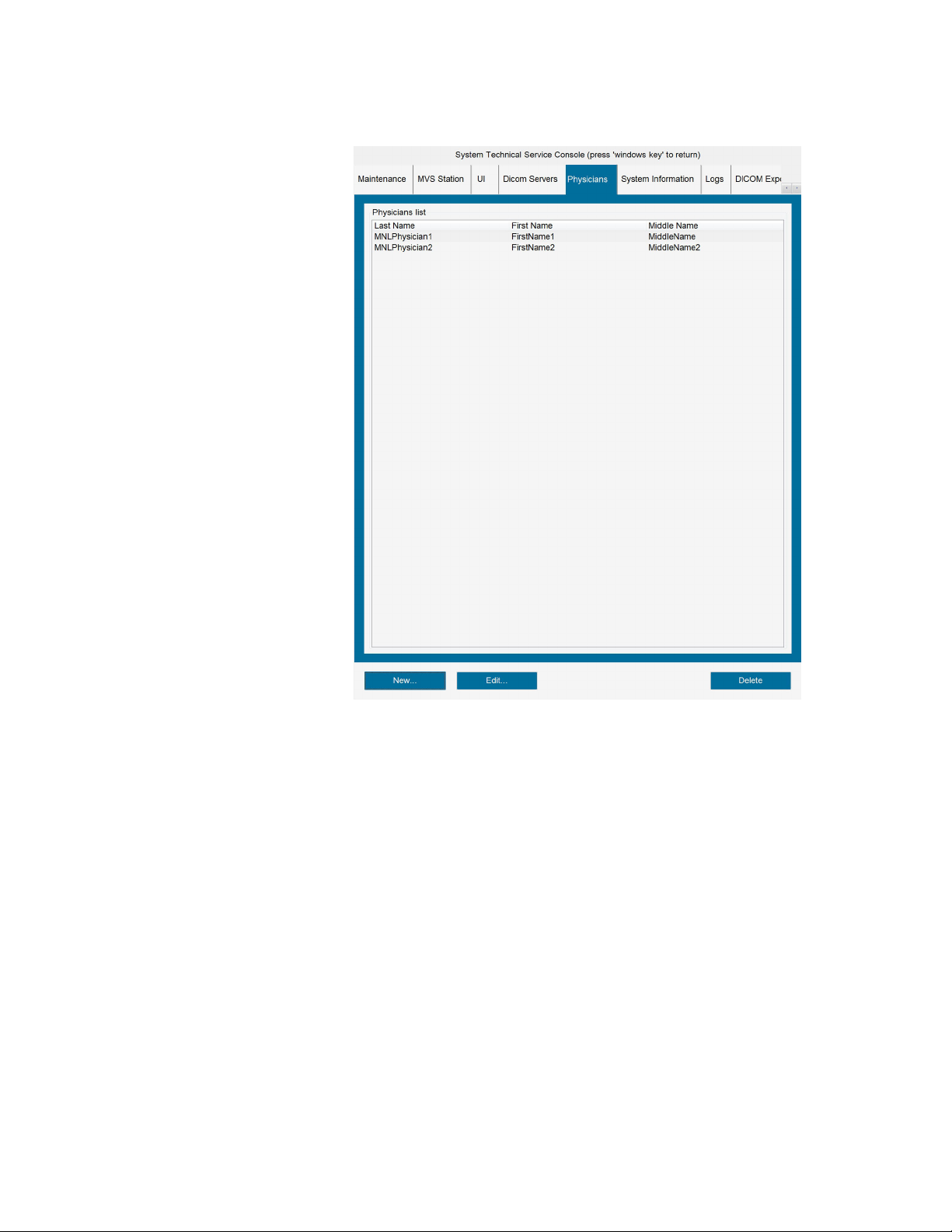
Powering Up and Configuring the System
Setting Up DICOM Export Configurations
Figure 53: Physicians List
You can add a new physician to the list, edit an entry, or delete a name from the list.
Adding a New Physician to the List
1. With the Physicians List open, click [New].
The Physician dialog box, shown in Figure 54, opens.
89
Page 90

Powering Up and Configuring the System
Setting Up DICOM Export Configurations
2. Type the physician’s Last and First names in the respective fields. A middle name is not
mandatory, but may be entered in the Middle Name field.
Note: You can cancel and close the Physician dialog at any time by clicking [Cancel].
3. Click [OK] to add the physician’s name and return to Physicians List, shown in Figure 53.
4. Check that the physician you entered appears in the list.
Figure 54: Physician dialog
5. Press the [Windows®] key on the keyboard to exit the System Technical Service
Console.
Editing Entries
1. With the Physicians List open, scroll through the list to locate the entry to be changed and click
on it.
2. Use the [Backspace] key to remove erroneous data, and type in the corrections.
3. Review the corrected entry and press [Enter].
Deleting a Name from the Physicians List
1. With the Physicians List open, select the name you wish to delete.
2. Click [Delete].
Optimizing the Monitor Display
Calibrating the Brightness, Contrast, and Gamma
The system offers a calibration test pattern to optimize brightness, contrast, and gamma settings. To
access the calibration page:
90
1. Open the System Technical Service Console.
a. Press [Ctrl] [Alt] [Home] on the keyboard to bring up the user access popup.
b. Type in your user name and password and press [Enter]. The System Technical Service
Console opens.
2. Open the Maintenance tab.
Page 91

Powering Up and Configuring the System
Setting Up DICOM Export Configurations
Figure 55: Maintenance tab page
Note: If the O-arm™ O2 Imaging System has the optional 2D Long Film mode, the Run Rad Gain
Calibration button on the Maintenance tab appears as Run 3D/2D Long Film RAD Gain
Calibration.
3. In the Monitor Calibration field, press [Adjust Display Settings] to open the calibration page.
91
Page 92

Powering Up and Configuring the System
Setting Up DICOM Export Configurations
Figure 56: Monitor calibration page
4. Use the Brightness, Contrast and Gamma slider bars 3 to adjust the settings. The
recommended setting is when both a somewhat lighter square is visible in the dark box
a somewhat darker square is visible in the light-colored box
5. When you are satisfied with the calibration, press [OK] 4 to close the calibration window.
6. Press the [Windows®] key on the keyboard to exit the System Technical Service
Console.
2.
1 and
92
Page 93

5 Setup in the Operating Room
This chapter describes the procedures to set up the O-arm™ O2 Imaging System in the operating
room.
Moving the System
Moving the IAS
Safety Precautions
Due to its mass, the IAS has battery-powered drive wheels to assist in its movement and positioning.
Warning: The Image Acquisition System (IAS) weighs approximately 885kg (1,950 lbs). Move the
IAS slowly using the battery-powered drive wheels. Do not disengage the drive wheel during
transport, especially on an incline. Use special care when crossing thresholds and moving up or
down ramps. Be aware of all obstacles and people along the path. Collision with people or
physical objects can result in personal injury or equipment damage.
Warning: The gantry must be in the docked position before you move the Image Acquisition System
(IAS). Use special care on steep slopes (>5º) and when crossing ramps and thresholds.
Using The Transport Handle
Figure 57: Transport handle control (IAS stand, partial top view)
The Transport Handle 1 on the IAS cabinet has a control bar 2 that you squeeze to apply power
to the rear wheels of the IAS.
93
Page 94

Setup in the Operating Room
Powering Up the System
To move the IAS, squeeze the control bar and then push or pull the transport handle. When you
release the bar, the wheels stop moving. Always stop movement before you release the bar.
• Squeezing the control bar and pushing on the handle moves the IAS forward.
• Squeezing the control bar and pulling on the handle moves the IAS backward.
Turning the IAS to the Left or Right
By applying differential pressure to either side of the handle, you can steer the IAS left or right.
Squeeze the bar and push the left side of the handle without applying pressure to the right side.
Squeeze the bar and push the right side of the handle without applying pressure to the left side.
Moving the MVS
Warning: The Mobile View Station (MVS) weighs approximately 159 kg (350 lbs). Use two people
to move the MVS up or down an incline. Never attempt to move the MVS up or down steps or
stairs.
1. Push up the wheel brake release bars to unlock the wheel brakes.
2. Grasp the handle on either side of the MVS and carefully maneuver it to its destination.
3. Press down on the wheel brakes to lock the wheels once the MVS is in its final location.
Powering Up the System
For the IAS and the MVS to function as a system, they must be physically connected to one another
via the MVS interconnect cable. This cable supplies power to the IAS and allows signal and data
transfers between the two units.
Connecting the IAS and MVS and Powering Up the System
1. Plug one end of the MVS interconnect cable into the J2 port on the IAS connector panel, as
shown in Figure
2. Plug the MVS power cable into a suitable wall outlet – one that is properly grounded and
matches the power rating listed on the MVS label.
Note: The MVS interconnect cable can be connected and disconnected regardless of whether the
line voltage is applied to the MVS.
3. Turn the key switch on the IAS connector panel counter-clockwise to the Enable position.
14 on page 46.
94
4. On the IAS power control panel, press the Power button to turn on the IAS. When the IAS is
turned on, the button will illuminate blue.
Page 95

Setup in the Operating Room
Powering Up the System
5. On the MVS Power Control Panel, press the Power button. When the system turns on, the
button will illuminate blue.
The system takes about three minutes to boot up and run through its power on self-test. During
the initializing period, the pendant display looks like that shown in Figure
Figure 58: Startup progress display
58.
Once the system successfully completes the self-test, it is ready for use.
Note: If any warning or failure messages appear on the MVS display or the pendant screen, contact
Medtronic Technical Service referred to on page 10.
Locating Home Position
The issue described here is not normal operation; it should arise only if there is a problem.
Upon startup, you may need to reset the gantry home position, which is the “zero” position of each
of the three [x, y, z] axes. In this case the pendant displays the following message: To calibrate
motion, hold [M] button on the pendant. Press door icon to open door.
Press and hold the [M] button on the pendant until the gantry’s motion ceases and the system
assumes its 2D fluoroscopic default mode.
If the IAS is not connected to the MVS, the pendant displays a message that the IAS is in Standalone
Mode discussed on page 35.
Connecting the Footswitch
The attending surgical team may choose whether or not to use the footswitch.
To connect the footswitch, remove it from the holder and plug it into its receptacle at the IAS
connector panel, as referred to in Figure
14 on page 46.
When not in use, store the footswitch in the holder located on the bottom left side of the MVS.
95
Page 96

Setup in the Operating Room
Powering Up the System
Connecting a Second Monitor
A second monitor using a DVI port can be connected to the MVS for remote viewing of the same
display appearing on the MVS primary monitor. Ensure the second monitor is the same resolution
as the primary monitor (2560 x 1600 pixels). Connect this second monitor into the MVS Connector
panel using the appropriate cable type and jack. See Figure
Warning: The use of accessory equipment not complying with the equivalent safety requirements of
this equipment may lead to a reduced level of safety of the resulting system. Consideration
relating to the choice shall include: a) Use of the accessory in the patient vicinity; and b) Evidence
that the safety certification of the accessory has been performed in accordance with IEC 606011 and/or the appropriate accessory requirements for that type of device, e.g. IEC 60950-1 for IT
Equipment.
Warning: When this device is connected with other electrical equipment, leakage currents may be
additive. To minimize total leakage current per patient, ensure that all systems are installed
according to the requirements of IEC 60601-1.
Note: The second monitor display does not update the image at the same frame rate as the main
MVS monitor, but it matches the original display when updating and scrolling ends.
21 on page 57.
Unpacking and Activating the Mouse
Overview
Medtronic Navigation supplies a sterile customized wireless mouse for use in the OR. It is designed
for single use, to be disposed of at the completion of the surgical procedure. Reuse could pose a risk
of infection to the patient.
The wireless mouse is sterilized using ethylene oxide. Do not attempt to re-sterilize the mouse.
Multiple sterilization cycles could result in damage to the circuitry or leave unacceptable levels of
ethylene oxide residue.
Warning: The wireless mouse is supplied in its packaging as a single-use sterile device. Be sure the
sterilization barrier and packaging are not compromised. Do not use the device if the package is
damaged. Do not resterilize.
Before the mouse can be used, it must be removed from its sterile package and activated so that the
™
O-arm
Symbols
O2 Imaging System recognizes it.
DO NOT USE IF PACKAGE IS DAMAGED.
DO NOT REUSE.
96
DO NOT RESTERILIZE.
STERILIZED USING ETHYLENE OXIDE.
Page 97
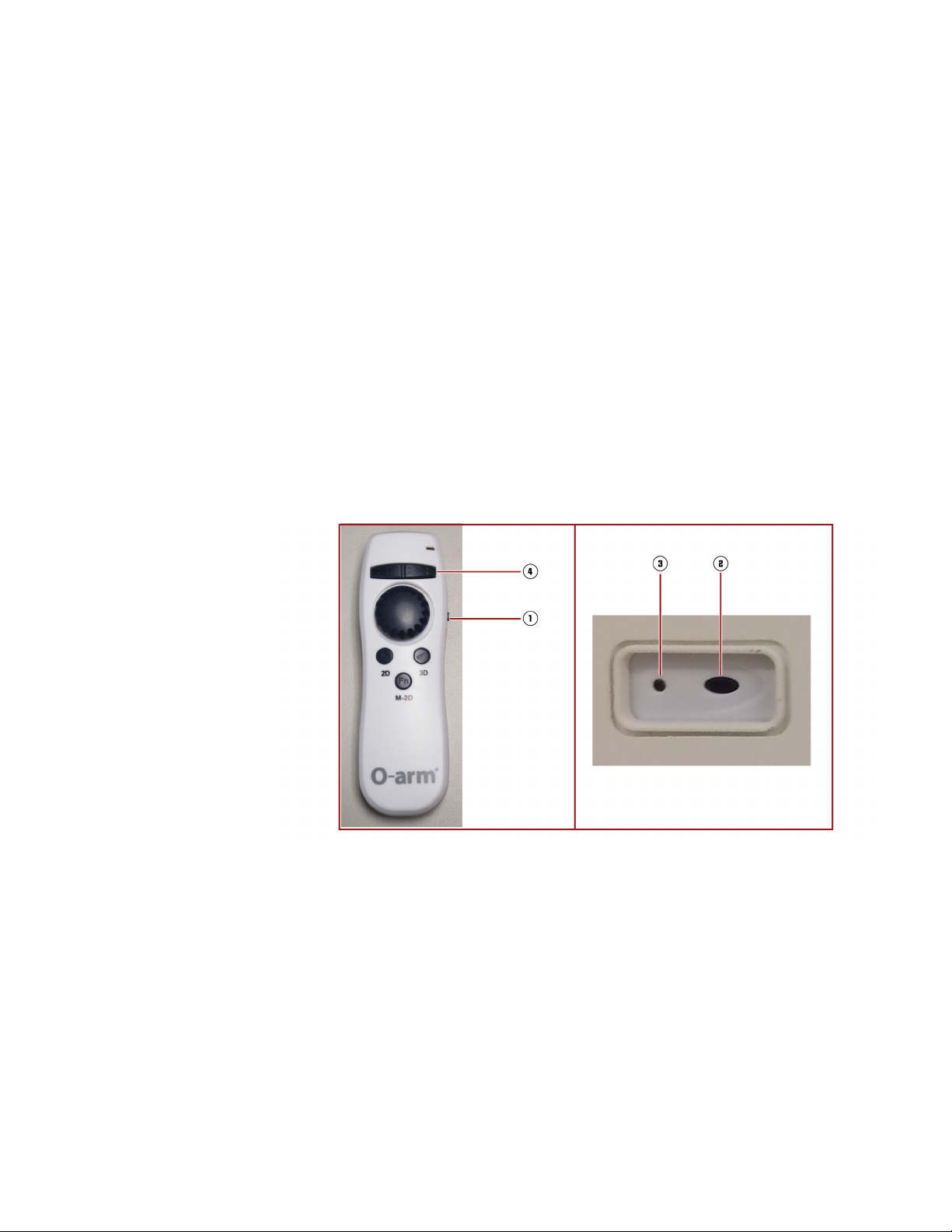
Setup in the Operating Room
Powering Up the System
Warning: Once you have removed the mouse from the sealed bag, do not take the mouse out of the
sterile field. If the mouse is removed from the sterile field, it will be contaminated, and must not
re-enter the sterile field.
Proper Disposal
The wireless mouse is considered medical waste. After use, dispose of it in accordance with all local
regulations. Reuse of the wireless mouse could pose a risk of infection to the patient.
Unpacking the Mouse and Maintaining Sterility
The wireless mouse (BI-900-00048), is supplied sterile in a sealed polyurethane bag. Use standard
operating room sterile field procedures to remove the mouse from the bag once the sterile field has
been created.
The activation procedure for the mouse requires two people: one sterile person holding the mouse
within the sterile field and a second person outside the sterile field at the MVS.
Wireless Mouse
Figure 59: Wireless mouse (Left) and receiver (Right)
Activating the Mouse
1. Push the On/Off switch 1 to On.
2. On the front of the MVS, press the Connect button 2 on the mouse receiver.
The LED on the mouse receiver 3 will begin flashing.
3. Within 20 seconds of pushing the Connect button, do the following:
a. Point the mouse at the receiver.
b. Press and hold the right mouse button 4 at least 5 seconds.
The LED may rapidly blink; this is okay.
97
Page 98
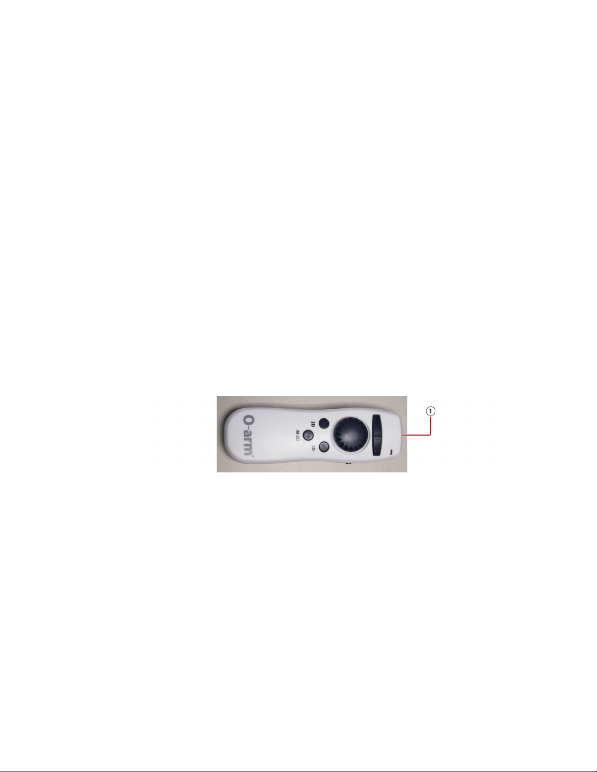
Setup in the Operating Room
Powering Up the System
4. Communication has been established between the receiver and the mouse. The mouse is now
ready for use. Refer to pages
Note: You may need to repeat the procedure if system does not respond to the mouse after the initial
attempt. This may be necessary for the mouse to find a clear communications channel. There
are five possible channels.
If a clear channel cannot be obtained, you can substitute the touch pad and function keys on the MVS
keyboard for the mouse.
Wireless Interference of the Mouse
During use of the mouse, you may encounter interference from other wireless devices operating in
the area. This is indicated by slow response to motion commands, or missed commands. If this
happens, repeat steps
Using the Laser Pointer on the Mouse
To use the mouse as a pointing device, point the front of the mouse at the target and press the laser
pointer trigger on the underside of the mouse.
149, 159, 166 and 191 on the use of the mouse.
2-4 of “Activating the Mouse”.
The wireless mouse emits Class 2 laser light.
Warning: Do not point laser radiation at audience.
Caution: Laser radiation. Do not stare into beam. Class 2 laser product.
Figure 60: Location of laser pointer aperture (1) on the O-arm™ wireless mouse.
Entering Patient Information
Opening the Exam Information Page
When the system powers up, the Exam Information page opens. If it does not appear, press [Esc]
on the keyboard.
98
Page 99
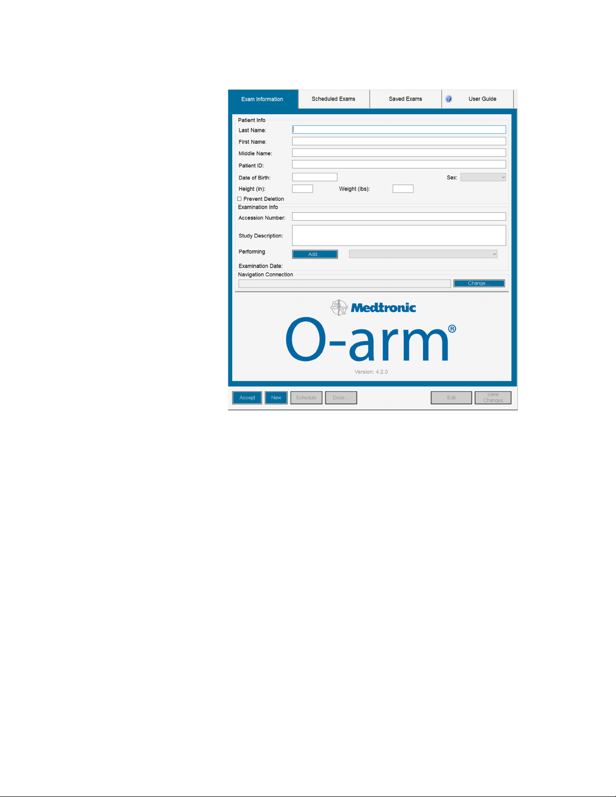
Figure 61: Exam Information page
Setup in the Operating Room
Powering Up the System
Options for Entering Patient Data
The following options apply to entering patient data:
• Enter new patient data at the time of the patient’s examination.
• Enter data ahead of the patient’s examination and place the patient in the Scheduled Exams List.
See Figure
• Open the Exam Information page to edit previous data entries, as discussed on page 99.
62.
Entering New Patient Data at Time of Examination
The Exam Information Page
The Exam Information page, shown in Figure 63, allows you to enter new patient data and access
existing patient records from the system’s database.
Use the MVS keyboard to type patient information into the text fields. A flashing cursor indicates
which text field you are in.
Use the [Tab] key or the touch pad to move between entries, and the [Backspace] key to correct
any typing errors.
99
Page 100

Setup in the Operating Room
Powering Up the System
Click [Cancel] to exit the patient information session at any time without saving any entered
information.
How to Enter Data for a New Patient
1. Under Patient Info, enter the following data:
–Last Name
– First Name
– Middle name (not required)
– Patient ID
– Date of Birth: type in the month, the day, and the year. The software assigns two digits for
– Sex: select Female, Male, or Other.
– Height/Weight
2. Select Prevent Deletion to ensure that the patient’s exam information cannot be automatically
deleted from the system’s database. See the “
214.
the day and month.
Automatic Patient Deletion” description on page
3. Under Examination Info, enter the following data:
– Accession Number
– Study Description (up to 64 characters)
– Performing Physician: Use the scroll bar to locate the physician’s name. Refer to Adding To
and Modifying the Physicians List on page 88 for directions on how to add a physician’s name
to the list. If you enter a name that is not in the list, a dialog asks if you want to add the name
to the list. Press [OK].
4. Review the information you entered to ensure its accuracy and make any necessary
corrections.
5. Do either of the following:
– Click [Accept] to save the patient information, exit the Exam Information page, and begin
the examination process; or
– Click [Save Changes] to save the current patient information and remain on Exam
Information page. To make further edits, click [Edit] and enter the new information.
Note: Even if you do not click [Accept] or [Save Changes], if you acquire images, the information
is saved to the system’s database.
Editing Patient Information
Once the Exam Information page leaves the screen, you cannot alter text fields without using the
[Edit] button.
100
When a new patient is entered into the patient database, preset memory locations are reset to their
default settings.
 Loading...