

Page 1

BATTERY SUPPORT SYSTEM 2
Operating Instructions
Page 2

Page 3
OPERATING INSTRUCTIONS
BATTERY SUPPORT SYSTEM 2
Page 4

IMPORTANT
!USA
RX only
This instrument is to be used by authorized personnel only.
!USA
Device Tracking
The U.S. Food and Drug Administration requires defibrillator manufacturers and distributors to track the
location of their defibrillators and many defibrillator accessories. The address to which this particular
equipment was shipped is now listed as the current tracking location. If the equipment is located
somewhere other than the shipping address or the equipment has been sold, donated, lost, stolen,
exported, or destroyed, or if the equipment was not obtained directly from Medtronic, please either call
the device tracking coordinator at 1.800.426.4448 or use one of the postage-paid address change
cards located in the back of this manual to update this vital tracking information.
Responsibility for Information
It is the responsibility of our customers to ensure that the appropriate person(s) within their organization
have access to this information, including general safety information provided in Section 1.
Medtronic Emergency Response Sys tems
11811 Willows Road Northeast
Redmond, WA 98052-2003 USA
Telephone: 425.867.4000
Toll Free (USA only): 800.442.1142
Fax: 425.867.4121
Internet: www.medtronic-ers.com
www.medtronic.com
LIFEPAK and FASTPAK are registered trademarks of Medtronic Emergency Response Systems, Inc. Medtronic is a registered trademark of
Medtronic, Inc. Specifications are subject to change without notice.
©1999–2004 Medtronic Emergency Response Systems, Inc. All rights reserved.
ii Battery Support System 2 Operating Instructions
Medtronic Europe S.A.
Medtronic Emergency Response Systems
Rte. du Molliau 31
Case postale 84
1131 Tolochenaz
Switzerland
Telephone: 41.21.802.7000
Fax: 41.21.802.7900
MIN 3010515-003 / CAT 26500-00 0168
Page 5

TABLE OF CONTENTS
1 Safety Information
Terms............................................................................................................................................. 1-2
General Warnings and Cautions.................................................................................................... 1-2
Symbols and Abbreviations ........................................................................................................... 1-3
Document Conventions.................................................................................................................. 1-4
2 Basic Orientation
Battery Support System 2.............................................................................................................. 2-2
The LIFEPAK and FASTPAK Family of Batteries.......................................................................... 2-2
Unpacking and Inspecting.............................................................................................................. 2-3
Controls, Indicators, and Connectors............................................................................................. 2-3
Inserting Batteries.......................................................................................................................... 2-5
3 Battery Maintenance
Battery Maintenance Warning........................................................................................................ 3-2
Battery Maintenance Guidelines and Procedures.......................................................................... 3-2
Receiving New Batteries................................................................................................................ 3-4
Storing Batteries ............................................................................................................................ 3-4
Discarding/Recycling Batteries ...................................................................................................... 3-5
4 Battery Support System 2 Maintenance
The Battery Support System 2 Service Indicator........................................................................... 4-2
Cleaning......................................................................................................................................... 4-2
Fuse Replacement......................................................................................................................... 4-2
Troubleshooting ............................................................................................................................. 4-3
Replacement Parts and Accessories............................................................................................. 4-4
Specifications................................................................................................................................. 4-4
Warranty Policy.............................................................................................................................. 4-6
Recycling Information .................................................................................................................... 4-6
Battery Supp ort System 2 Oper ating Instruc tions iii
©1999–2004 Medtronic Emergency Response Systems, Inc.
Page 6

Table of Contents
LIST OF FIGURES
Figure 2-1 LIFEPAK and FASTPAK Batteries........................................................................................2-2
Figure 2-2 Controls, Indicators, and Connectors....................................................................................2-3
Figure 2-3 Battery Fuel Gauge...............................................................................................................2-4
LIST OF TABLES
Table 2-1 Controls, Indicators, and Connectors....................................................................................2-3
Table 4-1 Troubleshooting Tips.............................................................................................................4-3
Table 4-2 Replacement Parts and Accessories ....................................................................................4-4
Table 4-3 Battery Support System 2 Specifications ..............................................................................4-4
Table 4-4 LIFEPAK and FASTPAK Battery Specifications....................................................................4-5
iv Battery Support System 2 Operating Instructions
Page 7
EC DECLARATION OF CONFORMITY*
Manufacturer’s Name: Medtronic Emergency Response Systems, Inc.
Manufacturer’s Address: 11811 Willows Road NE
Redmond, WA 98052-2003 USA
declares that the CE-marked product
Product Name: Battery Support System 2
Model Number(s):
3010035
*
complies with 93/42/EEC (Medical Device Directive) class I, conformity assessed per Annex 7.
This product complies with:
Safety: EN 61010-1 1993 amd. 1995 − Class I
− Pollution degree 2
− Installation Category II
EMC: EN 60601-1-2: 1993
Michael D. Willingham
Redmond, October 25, 2004
This declaration applies to CE-marked devices produced after the date of issuance of this declaration and
before it is either superseded by another declaration or withdrawn.
Authorized EC Representative: Medtronic B.V., Earl Bakkenstraat 10, 6422 PJ Heerlen, The Netherlands
Vice President, Regulatory Affairs
* This declaration does not apply to military configuration catalog number 99407-000018
Battery Supp ort System 2 Oper ating Instruc tions v
©1999–2004 Medtronic Emergency Response Systems, Inc.
Page 8

Page 9

1
SAFETY INFORMATION
This section provides important information to help you safely operate the Battery Support System 2.
Familiarize yourself with all of these terms, warnings, and symbols.
Terms page 1-2
General Warnings and Cautions 1-2
Symbols and Abbreviations 1-3
Document Conventions 1-4
Battery Supp ort System 2 Oper ating Instruc tions 1-1
©1999–2004 Medtronic Emergency Response Systems, Inc.
Page 10

Safety Information
TERMS
The following terms are used either in these operating instructions or on the Battery Support System 2:
Danger: Immediate hazards that will result in serious personal injury or death.
Warning: Hazards or unsafe practices that could result in serious personal injury or death.
Caution: Hazards or unsafe practices that could result in minor personal injury, product damage, or
property damage.
GENERAL WARNINGS AND CAUTIONS
The following are general warning and caution statements. Other specific warnings and cautions are
provided as needed in other sections of these operating instructions.
WARNINGS!
Shock or fire hazard.
Do not immerse any portion of this device in water or other fluids. Avoid spilling any fluids on the device
or accessories. Do not clean with alcohol, ketones, or other flammable agents. Do not autoclave or
sterilize this device unless otherwise specified.
Possible fire or explosion.
Do not use this device in the presence of flammable gases or anesthetics. Place the Battery Support
System 2 in the proper location as specified in these operating instructions.
Possible fire or explosion.
The Battery Support System 2 is designed to be used with Medtronic batteries only. Other
manufacturers’ batteries may overheat in this battery support system. Do not use with remanufactured
or alternate source batteries.
Possible loss of power during patient care.
Medtronic has no information regarding the performance or effectiveness of its LIFEPAK® defibrillator/
monitors if they are used with other manufacturers’ batteries or battery chargers. Using other
manufacturers’ batteries or battery chargers may result in device failure and may void warranty. Use
only Medtronic batteries and the appropriate Battery Support System.
Possible electrical Interference with device performance
Equipment operating in close proximity may emit strong electromagnetic or radio frequency
interference (RFI) which could affect the performance of this device. RFI may result in improper device
operation, distorted ECG, failure to detect a shockable rhythm, or cessation of pacing. Avoid operating
the device near cauterizers, diathermy equipment, cellular phones, or other portable and mobile RF
communications equipment. Maintain equipment separation of at least four feet and do not rapidly key
EMS radios on and off. Contact a technical support representative if assistance is required.
Possible electrical interference
Using cables, electrodes, or accessories not specified for use with this device may result in increased
emissions or decreased resistance to electromagnetic interference which could affect the performance
of this device or of equipment in close proximity. Use only parts and accessories specified in these
operating instructions.
CAUTIONS!
Possible equipment damage.
This device may be damaged by mechanical or physical abuse such as immersion in water or dropping.
If the device has been abused, remove it from use and contact a qualified service technician.
1-2 Battery Support System 2 Operating Instructions
Page 11
Safety Information
CAUTIONS!
Possible or potential inaccurate battery charge level indicator.
Using the Battery Support System (MIN 801807) or the two-well Battery Charger (MINs 9-00284,
9-00288, and 801530) to charge and maintain a FASTPAK
®
2 battery will eventually result in an
inaccurate battery charge level indicator. Use only the Battery Support System 2 (MIN 3010035) to
charge and maintain FASTPAK 2 batteries.
Possible equipment damage.
The supplied power cord is used to connect the battery support system to ac line voltage. Excessive
voltage may cause fuses in the Battery Support System 2 to blow. Before connecting the battery
support system, ensure that you are using a grounded outlet of the correct voltage.
Note: The Battery Support System 2 has no ON/OFF switch. When connecting the system to ac line
voltage, ensure that the power cord is easily accessible and is not obstructed in any way. If the system
malfunctions or overheats, disconnect the system from the ac line voltage by removing the power cord.
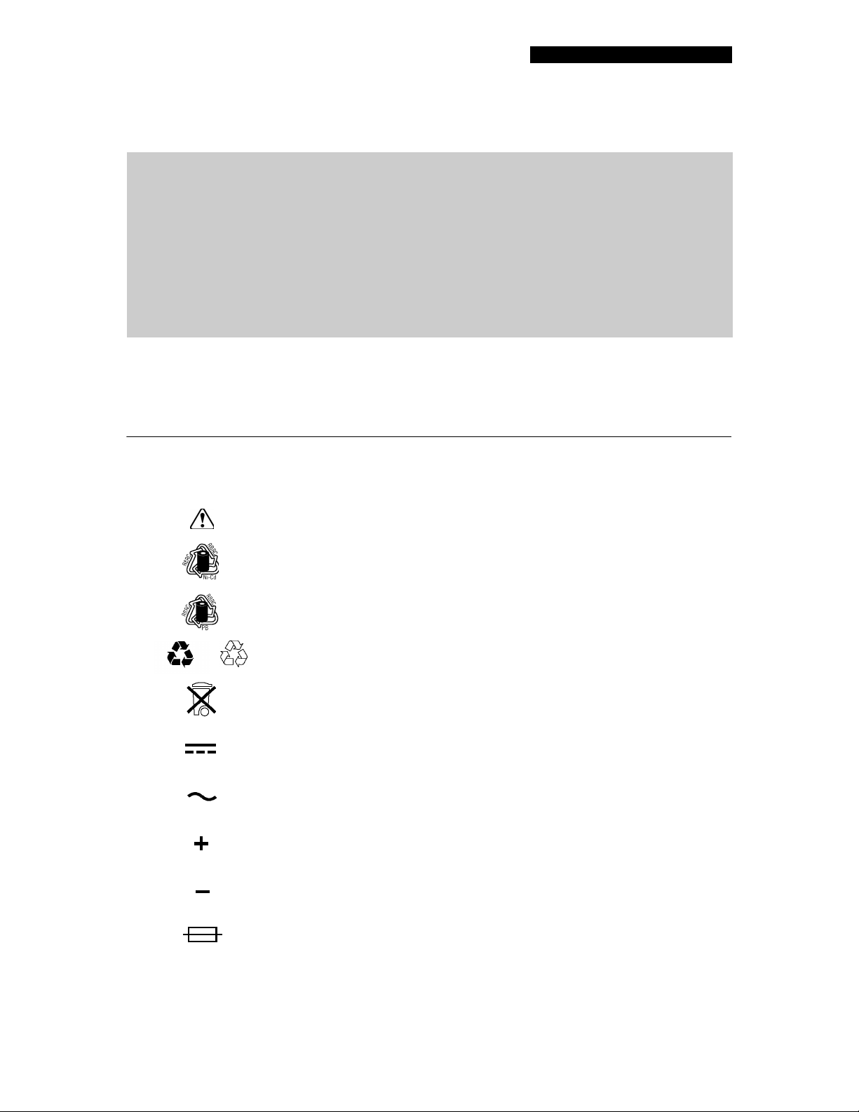
SYMBOLS AND ABBREVIATIONS
The symbols and abbreviations below may be found in these operating instructions, on the Battery
Support System 2, or on FASTPAK and LIFEPAK
®
batteries:
or
Attention, consult accompanying documents
Recycle NiCd battery
Recycle PB battery
See instructions for recycling procedures, 4-6
See instructions for disposal procedure, 3-5
Direct Current (DC)
Alternating Current (AC)
Positive terminal
Negative terminal
Fuse
Battery Supp ort System 2 Oper ating Instruc tions 1-3
©1999–2004 Medtronic Emergency Response Systems, Inc.
Page 12

Safety Information
Type B equipment
Indoor use only
LOT
YYWW
YYYY
Hz
V
A
W
T
LED
NiCd
SLA
Lot code
Date of manufacture
Canadian Standards Association certification for Canada and the United
States
Marking of conformity according to the Medical Device Directive 93/42/EEC
Hertz (frequency)
Volts
Amperes
Watts
Time lag fuse conforming to IEC 127
Light Emitting Diode
Nickel Cadmium chemistry battery
Sealed Lead Acid chemistry battery
MIN
CAT
!USA
Manufacturer’s Item Number
Catalog number used for placing orders
For USA audiences only.
DOCUMENT CONVENTIONS
Text references to system buttons and labels are indicated in capital letters, for example: CHARGE.
1-4 Battery Support System 2 Operating Instructions
Page 13

2
BASIC ORIENTATION
This section provides a basic orientation to the Battery Support System 2.
Battery Support System 2 page 2-2
The LIFEPAK and FASTPAK Family of Batteries 2-2
Unpacking and Inspecting 2-3
Controls, Indicators, and Connectors 2-3
Inserting Batteries 2-5
Battery Supp ort System 2 Oper ating Instruc tions 2-1
©1999–2004 Medtronic Emergency Response Systems, Inc.
Page 14

Basic Orientation
BATTERY SUPPORT SYSTEM 2
The Battery Support System 2 provides charging, conditioning, and shelf-life testing for the LIFEPAK
and FASTPAK batteries.
The Battery Support System 2:
• Provides a clear indication that a battery is charging, ready for use, or needs to be discarded.
• Can charge, condition, or shelf-life test up to three LIFEPAK and FASTPAK batteries at one time.
• Is provided with a detachable power cord that connects to a grounded ac outlet.
• Has a wall mount bracket (optional) that permits horizontal or vertical mounting.
THE LIFEPAK AND FASTPAK FAMILY OF BATTERIES
WARNING!
Possible explosion.
Attempting to charge a LIFEPAK 5 battery in the Battery Support System 2 may cause the battery to
explode. Do not charge LIFEPAK 5 batteries in the Battery Support System 2.
All the batteries shown in Figure 2-1 can be used in the LIFEPAK 12 defibrillator/monitor series, but
only the FASTPAK batteries can be used in other LIFEPAK defibrillator/monitors. The LIFEPAK
batteries can only be used in the LIFEPAK 12 defibrillator/monitor.
Medtronic
*
LIFEPAK NiCd battery
MIN 3009376
Figure 2-1 LIFEPAK
†
*
and FASTPAK† Batteries
Medtronic
LIFEPAK SLA battery
MIN 3009378
†
FASTPAK 2 battery
MIN 3009375
†
FASTPAK battery
MIN 9-10424-19 (gold)
MIN 9-10424-18 (white)
LIFEPAK NiCd, FASTPAK, and FASTPAK 2 batteries have a nickel cadmium (NiCd) chemistry and
LIFEPAK SLA batteries have a sealed lead acid (SLA) chemistry. In addition, the LIFEPAK NiCd and
FASTPAK 2 batteries have a charge level indicator (fuel gauge).
Charge FASTPAK batteries in either the Battery Support System (MIN 801807), the Battery Support
System 2 (MIN 3010035), or the LIFEPAK 12 defibrillator when it is powered by the AC or DC Power
Adapter. FASTPAK batteries require periodic conditioning and shelf-life testing to optimize performance.
Condition and shelf-life test FASTPAK batteries in the Battery Support System or Battery Support
System 2.
Charge the FASTPAK 2 battery in the Battery Support System 2 or in the LIFEPAK 12 defibrillator when
it is powered by the AC or DC Power Adapter. Using the Battery Support System (MIN 801807) or the
two-well Battery Charger (MINs 9-00284, 9-00288, and 801530) to charge and maintain a FASTPAK 2
battery will eventually result in an inaccurate battery charge level indicator. FASTPAK 2 batteries
require periodic conditioning and shelf-life testing to optimize performance. Condition and shelf-life test
FASTPAK 2 batteries only in the Battery Support System 2.
* Approved for military use
† Not approved for military use
2-2 Battery Support System 2 Operating Instructions
Page 15

Basic Orientation
Charge LIFEPAK NiCd and SLA batteries either in the Battery Support System 2 or in the LIFEPAK 12
defibrillator when it is powered by the AC or DC Power Adapter. LIFEPAK NiCd batteries require
periodic conditioning and shelf-life testing to optimize performance. Periodic conditioning and shelf-life
testing may optimize SLA battery performance. Condition and shelf-life test LIFEPAK NiCd and SLA
batteries in the Battery Support System 2.
UNPACKING AND INSPECTING
Remove the Battery Support System 2, ac power cord, and product literature from the shipping
container. Carefully inspect the system and the power cord for any signs of damage during shipping.
Verify the receipt of everything noted in the packing list. Save the shipping container and the foam
inserts in case the system needs to be returned.
CONTROLS, INDICATORS, AND CONNECTORS
Figure 2-2, Figure 2-3, and Table 2-1 provide an overview of the controls, indicators, and connectors for
the Battery Support System 2 and FASTPAK 2 batteries.
9
8
7
6
5
4
3
Figure 2-2 Controls, Indicators, and Connectors
Table 2-1 Controls, Indicators, and Connectors
Callout Item Description
1
2
3
4
SERVICE
POWER
SHELF LIFE
CONDITION
Indicates Battery Support System 2 needs service.
Indicates power is on.
Amber LED indicates battery is undergoing a shelf-life test.
Amber LED indicates battery is conditioning.
12
10, 11
1
2
Battery Supp ort System 2 Oper ating Instruc tions 2-3
©1999–2004 Medtronic Emergency Response Systems, Inc.
Page 16

Basic Orientation
Table 2-1 Controls, Indicators, and Connectors (Continued)
Callout Item Description
5
6
CHARGE
DISCARD
Amber LED indicates battery is charging.
Indicates battery should be removed from use and
discarded/recycled.
7
READY
Indicates battery is ready for use.
8 + /– Terminals Transfer charge current onto battery.
9 Communication Pins Provide digital communication between the Battery Support
System 2 and the battery.
10 AC Power Input
Receptacle for ac power cord.
Receptacle
11 Fuses Two fuses help protect the Battery Support System 2 from
current surges.
12 Power Cord Cable for operation from an ac outlet.
14
13
Figure 2-3 Battery Fuel Gauge
13 Fuel Gauge Button Lights the fuel gauge indicators.
14 Fuel Gauge
Indicators
One to four lights indicate the relative charge of the battery,
with four lights indicating maximum charge.
One light flashing: charge battery.
Two alternately flashing lights: battery requires conditioning.
No lights: battery has 0% charge or needs to be discarded.
2-4 Battery Support System 2 Operating Instructions
Page 17

Basic Orientation
INSERTING BATTERIES
CAUTION!
Failure to charge batteries.
Battery pins in the battery support system may be damaged if the batteries are dropped or forced into
the battery wells. Inspect the battery pins routinely for signs of damage.
Routinely inspect batteries for damage or leakage. Discard/recycle damaged or leaking batteries.
To insert a battery into a battery well:
1 Inspect the +/- terminals (pins) in the battery well for signs of damage.
2 Inspect the battery well for signs of damage or distortion.
3 Align the battery so that the battery clip is over the pins in the battery well.
4 Insert the end of the battery opposite the battery clip into the battery well.
5 Firmly press the other end into the battery well until it clicks into place.
To remove the battery, press the battery clip in and lift the battery out of the battery well.
Battery Supp ort System 2 Oper ating Instruc tions 2-5
©1999–2004 Medtronic Emergency Response Systems, Inc.
Page 18

Page 19

3
BATTERY MAINTENANCE
This section describes how to use the Battery Support System 2 to maintain LIFEPAK and FASTPAK
batteries.
Battery Maintenance Warning page 3-2
Battery Maintenance Guidelines and Procedures 3-2
Receiving New Batteries 3-4
Storing Batteries 3-4
Discarding/Recycling Batteries 3-5
Battery Supp ort System 2 Oper ating Instruc tions 3-1
©1999–2004 Medtronic Emergency Response Systems, Inc.
Page 20

Battery Maintenance
BATTERY MAINTENANCE WARNING
WARNING!
Possible loss of power and delay of therapy during patient care.
Using an improperly maintained battery to power the defibrillator may cause power failure without
warning. Use the appropriate Medtronic Battery Support System to charge and condition batteries.
BATTERY MAINTENANCE GUIDELINES AND PROCEDURES
To maximize Battery Support System 2 operation and battery performance and life, observe these
guidelines:
• Place the system in the proper location.
• Charge batteries at room temperature.
• Rotate batteries.
• Condition batteries every three months.
• Perform shelf-life tests every six months (optional for LIFEPAK SLA).
Place the Battery Support System 2 in the Proper Location
To help ensure proper system functioning:
• Place the system in a dry, well-ventilated area.
• Keep at room temperature.
• Keep batteries in wells.
• Do not place in direct sunlight.
• Do not place near a heat source or an air conditioner.
• Keep fan vent on back panel unobstructed.
Charge Batteries at Room Temperature
Charging batteries at room temperature, 20° to 25°C (68° to 78°F), is preferred to maximize battery
performance and life. The extreme temperature range for charging batteries is 5° to 35°C (41° to 95°F).
Batteries charged outside this temperature range may not reach a full charge (even if charging time is
increased) and irreversible cell damage could occur.
CAUTION!
Possible battery damage.
Charging a battery at temperatures below 5°C (41°F) or above 35°C (95°F) prevents the battery from
reaching full capacity and may cause irreversible cell damage.
Note: Fully charge SLA batteries between uses. If SLA batteries are not 100% recharged between
uses, sulfation (lead sulfate buildup on electrode surfaces inside the battery) can occur. Sulfation
reduces battery capacity and may result in premature battery failure.
To charge a battery:
1 Insert a battery into a Battery Support System 2 battery well.
CHARGE LED lights and charging
begins automatically.
READY lights when a battery reaches full charge. The battery may remain in the battery well until
2
needed. The system supplies a trickle charge that prevents overcharging and maintains the battery
at peak capacity.
Note: Withdrawing the battery from the charger before a
READY indication may result in an
inadequate charge.
Note: If
3-2 Battery Support System 2 Operating Instructions
DISCARD lights, remove the battery from use and discard/recycle (refer to page 3-5).
Page 21

Battery Maintenance
Rotate Batteries
Rotate all batteries in active use so that they are used with equal frequency.
Condition Batteries Every Three Months
Note: LIFEPAK SLA batteries do not require periodic conditioning. However, the Condition mode
may be used to test SLA battery capacity, or to determine whether an SLA battery is usable.
Voltage depression is a condition that reduces battery performance. When NiCd batteries repeatedly
receive a shallow discharge (that is, not allowed to drain completely between charging cycles), voltage
depression occurs. This condition is often mistakenly called “memory.” Voltage depression can usually
be reversed by conditioning the battery every three months.
Conditioning is a series of charge/deep discharge cycles performed in the Battery Support System 2 to
measure and optimize battery capacity.
Note: If a LIFEPAK NiCd or a FASTPAK 2 battery requires conditioning, the
and the conditioning procedure begins automatically. If the
CONDITION LED lights for a LIFEPAK
CONDITION LED lights
SLA battery, the battery is near the end of its useful life and replacement will soon be required.
To condition a battery:
1 Insert the battery into any battery well. Allow the LIFEPAK or FASTPAK 2 batteries to complete the
condition cycle.
2 Press
3
CONDITION for other FASTPAK batteries.
READY lights when a battery is fully recharged. The Battery Support System 2 automatically
recharges a battery that passes the conditioning process.
Note: If
DISCARD lights, remove the battery from use and discard/recycle.
Note: If a power failure occurs during battery conditioning, the Battery Support System 2 interrupts
conditioning and reverts to Charge mode once power is restored. Battery conditioning may not have
been completed. Repeat conditioning process.
Perform Shelf-Life Testing Every Six Months
Batteries self-discharge when not in use. A new NiCd battery self-discharges approximately 10% of its
capacity in the first day and 1% of its capacity every day thereafter when stored at room temperature. In
10 days, a new NiCd battery loses approximately 20% of its capacity.
SLA batteries have a low self-discharge rate. A new SLA battery self-discharges approximately 0.1% of
its capacity each day when stored at room temperature. In 10 days, a new SLA battery loses
approximately 1.0% of its capacity.
The actual rate of battery self-discharge depends on:
• Battery age
• Temperature
• Frequency of use
• Length of time in storage
• Physical condition
These factors can combine to significantly increase the battery discharge rate. For example, an older
NiCd battery stored at higher temperatures may have an accelerated self-discharge rate much greater
than 1% a day. The self-discharge rate increases as the battery ages.
Battery Supp ort System 2 Oper ating Instruc tions 3-3
©1999–2004 Medtronic Emergency Response Systems, Inc.
Page 22

Battery Maintenance
NiCd batteries (LIFEPAK NiCd, FASTPAK, and FASTPAK 2) may exhibit an increased self-discharge
rate during the first 24 hours after charging. At room temperature 20°C (68°F), their capacity may be
reduced by as much as 5%, during this time period. It is therefore important to charge and maintain
batteries in a room-temperature environment.
LIFEPAK NiCd and FASTPAK 2 batteries may communicate this charge reduction by extinguishing one
or two bars (lights) on their fuel gauge display after 24 to 48 hours. It is important to remember that the
fuel gauge on these batteries provides a conservative indication of battery capacity. Normally, there will
be more battery capacity available than the fuel gauge indicates.
The shelf-life test evaluates the self-discharge rate of a battery. Any battery that fails the shelf-life test
(
DISCARD lights) should be removed from use and discarded/recycled.
To perform a shelf-life test:
1 Complete the conditioning procedure.
2 Remove the battery from the Battery Support System 2 and store for 7 days at room temperature.
3 After storage, insert the battery into a battery well and press
4 Verify that the
5
READY lights when the battery passes the shelf-life test and is fully recharged. The battery may then
SHELF LIFE LED lights.
SHELF LIFE within 3 seconds.
be returned to use.
Note: If a power failure occurs during shelf-life test, the Battery Support System 2 interrupts the
shelf-life test and reverts to
CHARGE mode once power is restored. shelf-life test may not have been
completed. Repeat the shelf-life test.
Note: If
DISCARD lights, remove the battery from use and discard/recycle.
RECEIVING NEW BATTERIES
When newly-purchased batteries are received, charge each new battery. Because batteries selfdischarge during storage, a new battery may not be fully charged when it is received.
STORING BATTERIES
WARNING!
Possible loss of power during patient care.
Stored batteries lose charge. Failure to charge a stored battery before use may cause device power
failure without warning. Always charge a stored battery before placing it in active use.
Store batteries in or out of the Battery Support System 2 except when performing the shelf-life test.
During storage, batteries still require routine maintenance (refer to the conditioning procedure,
page 3-3, and the shelf-life test, page 3-3).
Storing an SLA battery that is less than 100% charged can result in permanent damage.
When storing batteries:
• Fully charge LIFEPAK SLA batteries before storing.
• Store batteries between 4.4° and 26.7°C (40° to 80°F). Lower temperatures reduce the battery self-
discharge rate. Higher temperatures increase the self-discharge rate.
• Do not freeze batteries. Damage to the battery may result.
• Charge stored batteries before placing in use.
3-4 Battery Support System 2 Operating Instructions
Page 23

Battery Maintenance
DISCARDING/RECYCLING BATTERIES
Properly maintained FASTPAK batteries have a useful life of approximately two years. Properly
maintained LIFEPAK NiCd and FASTPAK 2 batteries have a useful life up to five years. Properly
maintained LIFEPAK SLA batteries have a useful life of up to three years. A LIFEPAK NiCd,
LIFEPAK SLA, FASTPAK, or FASTPAK 2 battery has reached the end of useful life if
the following circumstances occur:
• Battery fails conditioning or shelf-life test.
• There is physical damage to the battery case.
• The battery is leaking.
• The Battery Support System 2 indicates
DISCARD during any battery maintenance procedure.
Note: The LIFEPAK NiCd, LIFEPAK SLA, and FASTPAK 2 batteries have internal parameters that
establish limits for useful life. If these parameters are exceeded, the Battery Support System 2 will
indicate
DISCARD when battery is inserted into the battery well.
To promote awareness of battery recycling, Medtronic LIFEPAK and FASTPAK batteries are marked
with one of these symbols:
one or more
of
When a LIFEPAK or FASTPAK battery reaches the end of its useful life, recycle the battery as follows:
Battery Recycling in the USA
Recycle batteries by participating with Medtronic in a national battery recycling program. Contact your
local Medtronic representative to obtain shipping instructions and shipping containers. Do not return
your batteries to the Medtronic offices in Redmond, Washington, unless instructed to do so by your
Medtronic representative.
Battery Recycling Outside the USA
Recycle batteries according to national and local regulations. Contact your local Medtronic
representative for assistance.
Battery Supp ort System 2 Oper ating Instruc tions 3-5
©1999–2004 Medtronic Emergency Response Systems, Inc.
Page 24

Page 25

4
BATTERY SUPPORT SYSTEM 2 MAINTENANCE
This section describes the Battery Support System 2 maintenance.
The Battery Support System 2 Service Indicator page 4-2
Cleaning 4-2
Fuse Replacement 4-2
Troubleshooting 4-3
Replacement Parts and Accessories 4-4
Specifications 4-4
Warranty Policy 4-6
Recycling Information 4-6
Battery Supp ort System 2 Oper ating Instruc tions 4-1
©1999–2004 Medtronic Emergency Response Systems, Inc.
Page 26

Battery Support System 2
THE BATTERY SUPPORT SYSTEM 2 SERVICE INDICATOR
WARNING!
Shock hazard.
Do not disassemble the battery support system. It contains no operator-serviceable components and
dangerous high voltages may be present. Contact a qualified service technician for repair.
When the Battery Support System 2 ac power cord is inserted into an ac power receptacle, the system
performs a series of self-diagnostic tests. Power-up testing is indicated by all the system indicator lights
briefly illuminating. If self-testing is successful all the indicators (except
Battery Support System 2 fails any power-up self-test,
SERVICE lights. Remove the system from use and
contact a qualified service representative for repair.
Periodically inspect the system for damage or cracks. Check that it is completely closed. Inspect the
power cord for damage, cracks, or bent pins.
The system does not contain any operator-serviceable components. If the system requires service,
contact a qualified service representative. When calling Medtronic to request service, have the following
information available: model number, serial number, and a description of the problem. If the system
must be sent to a service center or factory, repack it in the original shipping container to prevent
shipping damage.
Test modes, service protocols, fault codes, and other maintenance procedures are described in the
Battery Support System 2 Service Manual
. In the USA, call 1.800.442.1142 for technical consultation,
manuals, or parts. Outside the USA, contact your local Medtronic service office.
POWER) extinguish. If the
CLEANING
Clean the Battery Support System 2 case, battery contacts, batteries, and ac power cord with a damp
sponge or towel. The following agents may be used:
• Mild soap and water
• Quaternary ammonium compounds
• Isopropyl alcohol
• Peracetic (peroxide) acid solutions
CAUTION!
Possible equipment damage.
Do not clean any part of the battery support system or ac power cord with bleach, bleach dilution,
ketones, solvents, flammable agents,
autoclave, or gas-sterilize the battery support system.
phenolic compounds, or abrasive agents. Do not steam,
FUSE REPLACEMENT
The Battery Support System 2 has two fuses that help provide protection against over current. To
replace the fuses, open the fuse carrier door (located in the power input module) with a flat-bladed
screw driver. Verify that the replacement fuses are the same type and rating as listed in the
specifications in Table 4-3.
When replacing fuses in the system, use only 5 x 20 mm T 250V fuses approved to IEC 127-2, sheet 1
or 2, such as:
• Schurter FST
• Bussman GDC
• Littelfuse 218
Note: Use of other fuses may cause premature failure of the mains fuse.
4-2 Battery Support System 2 Operating Instructions
Page 27

Battery Support System 2
TROUBLESHOOTING
Refer to the troubleshooting tips in Table 4-1. If these troubleshooting tips do not resolve your question,
remove the Battery Support System 2 from active use and contact a qualified service representative. To
contact Medtronic in the USA, call 1.800.442.1142. Outside the USA, contact your local Medtronic
sales or service office.
Table 4-1 Troubleshooting Tips
Observation Possible Cause Corrective Action
POWER does not light when the
ac power cord is inserted into an
ac power receptacle.
CHARGE/CONDITION does not
light when a FASTPAK battery is
installed.
READY does not light after hours
of charging.
DISCARD illuminates. Battery is at end of useful life. Remove from use and discard/
Battery powers system for less
than the expected time.
SHELF LIFE LED does not light. Conditioned battery was not
Power cord not properly
connected.
Make sure that the power cord is
securely connected at both ends.
Blown fuses. Replace fuses using the
procedure described on page 4-2
with the type of fuses specified in
Table 4-3.
Inoperative ac outlet or tripped
circuit breaker in building.
Remove from use and contact a
qualified service
representative.
Battery malfunction. Install a different battery in the
same battery well. If
CONDITION
lights, discard/recycle
CHARGE/
the original battery.
Battery Support System 2
malfunction.
Battery does not charge to full
capacity (battery requires
Remove from use and contact a
qualified service
representative.
Perform the conditioning
procedure (page 3-3).
conditioning).
Battery charged at excessively
high or low temperatures.
Perform the conditioning
procedure (page 3-3) at the
correct temperature.
recycle.
Battery needs conditioning. Perform the conditioning
procedure (page 3-3). If the
battery is still not performing to
expectations, perform a shelf-life
test (page 3-3).
Condition, remove, and store
removed and stored prior to
shelf-life test.
battery for 7 days prior to shelf-
life testing.
Battery Supp ort System 2 Oper ating Instruc tions 4-3
©1999–2004 Medtronic Emergency Response Systems, Inc.
Page 28

Battery Support System 2
REPLACEMENT PARTS AND ACCESSORIES
In the USA, call 1.800.442.1142 to order parts and accessories. Outside the USA, contact your local
Medtronic sales or service office.
Table 4-2 Replacement Parts and Accessories
Description Part Number
Battery Support System 2 Operating Instructions 3010515
Battery Support System 2 Service Manual 3011409
LIFEPAK NiCd Battery 3009376
LIFEPAK SLA Battery 3009378
FASTPAK 2 Battery 3009375
FASTPAK Battery (white) 9-10424-18
FASTPAK Battery (gold) 9-10424-19
AC Input Power Cord 803650
Battery Support System 2 Wall Mount Bracket 3010932
SPECIFICATIONS
Table 4-3 lists the specifications for the Battery Support System 2.
Table 4-3 Battery Support System 2 Specifications
*
Function Description
General Specifications:
Dimensions 31.5 cm x 37.6 cm x 9.7 cm (12.4 inches x 14.8 inches x 3.8 inches)
Weight 8.2 kg (< 18 pounds) (excluding batteries)
Number of battery wells 3. Charging, conditioning, and shelf-life test capability in all battery wells.
Power requirements: 100/120/220/240 +
10%, 50/60 Hz + 3 Hz
Fuses Two fuses in the power input module (5 x 20 mm T 250V, Low or High break
capacity) per IEC 127-2, sheet 1 or 2, such as Bussman GDC, Littelfuse
218, or Schurter FST.
100/120 Volt Input: 1.6 Amp (T, or Time-Lag)
220/240 Volt Input: 0.8 Amp (T, or Time-Lag)
Environmental Specifications:
Liquid Ingress IPX0 per IEC529. Not protected against ingression of fluids. Indoor use only.
Altitude, operating To 4,572m (15,000 feet)
Altitude, non-operating To 5,500m (18,045 feet)
Humidity 0 to 95%
Temperature, operating
5° to 45°C (41° to 113°F) (commercial)
0° to 50°C (32° to 122°F) (military configuration)**
Temperature, storage
-40° to 70°C (-40° to 158°F) (commercial)
-46° to 71°C (-51° to 160°F) (military configuration)**
Vibration IEC 68-2-6 (commercial)
Military Configuration:
**
USAF: MIL-STD-810F Method 514.5, Jet Aircraft (Figure 514.5C-6 and
Table 514.5C-VIII (General Exposure), 3.54 Grms, 30 min/axis) and
Turboprop (C130 curve, 4.87 Grms, 60 min/axis)
USAARL: MIL-STD-810E Method 514.4 (1.58 Grms, 60 min/axis)
* All specifications are at 20°C unless otherwise stated.
** Catalog Number 99407-000018
4-4 Battery Support System 2 Operating Instructions
Page 29

Battery Support System 2
Table 4-4 LIFEPAK and FASTPAK Battery Specifications
*
LIFEPAK NiCd
Battery Type Nickel cadmium
Weight 0.77 kg (1.7 lbs)
Voltage 12Vdc
Capacity 1.7 amp hours (3009376-00)
2.4 amp hours (3009376-01)
Charge Time (fully depleted battery) 2.25 hours (3009376-00)
3 hours (3009376-01)
Conditioning Time 8 hours typical, 10 hours maximum (3009376-00)
9 hours typical, 11 hours maximum (3009376-01)
Charging Temperature Range 5° to 35°C (41° to 95°F)
Operating Temperature Range 0° to 50°C (32° to 122°F)
Long Term (>1 day) Storage Temperature
0° to 35°C (32° to 95°F)
Range
LIFEPAK SLA
Battery Type Sealed lead acid
Weight 1.4 kg (3.0 lbs)
Voltage 12Vdc
Capacity 2.5 amp hours
Charge Time (fully depleted battery) 6 hours typical, 12 hours maximum
Conditioning Time 28 hours typical, 56 hours maximum
Charging Temperature Range 5° to 35°C (41° to 95°F)
Operating Temperature Range 0° to 50°C (32° to 122°F)
Long Term (>1 day) Storage Temperature
0° to 35°C (32° to 95°F)
Range
FASTPAK and FASTPAK 2
Battery Type Nickel cadmium
Weight 0.7 kg (1.5 lbs)
Voltage 12Vdc
Capacity 1.2 amp hours
Charge Time (with fully depleted battery) 1.5 hours
Conditioning Time 7 hours typical, 8 hours maximum
Charging Temperature Range 5° to 35°C (41° to 95°F)
Operating Temperature Range 0° to 50°C (32° to 122°F)
Long Term (>1 day) Storage Temperature
0° to 35°C (32° to 95°F)
Range
* All specifications are at 20°C unless otherwise stated
Battery Supp ort System 2 Oper ating Instruc tions 4-5
©1999–2004 Medtronic Emergency Response Systems, Inc.
Page 30

Battery Support System 2
WARRANTY POLICY
The Battery Support System 2 is warranted against all defects in materials and workmanship for a
period of one year from the date of delivery.
All batteries supplied by Medtronic for LIFEPAK defibrillator/monitor products are warranted for a period
of one year. If Medtronic receives notice of a battery defect during the warranty period, we will replace
the battery upon verification of the defect.
Use of other manufacturers’ batteries and accessories with Medtronic defibrillator/monitor products may
void Safety Agency Certifications and warranty.
RECYCLING INFORMATION
Recycle the system at the end of its useful life.
Recycling Assistance
The system should be recycled according to national and local regulations. Contact your local
Medtronic representative for assistance.
Preparation
The system should be clean and contaminant-free prior to being recycled.
Recycling of Disposable Electrodes
After using disposable electrodes, follow your local clinical procedures for recycling.
Packaging
Packaging should be recycled according to national and local regulations.
4-6 Battery Support System 2 Operating Instructions
Page 31

Index
INDEX
Symbols
+/- Terminals 2-4, 2-5
A
Abbreviations 1-3
AC input power cord 2-4, 4-4
AC power input receptacle 2-4
B
Basic orientation 2-1
Battery
Capacity 3-3, 4-5
Charging 3-2, 4-5
Conditioning 3-3, 4-5
Discarding 3-4
FAST PA K 2-2, 3-3–3-5, 4-4, 4-5
Inserting 2-5
LIFEPAK SLA 2-2, 3-2–3-5,
4-4, 4-5
Maintenance 3-2
Memory 3-3
NiCd 2-2, 3-3
Receiving 3-4
Recycling 3-4, 3-5
Removing 2-5
Rotating 3-3
SLA 3-3
Specifications 4-4
Storing 3-4, 4-4, 4-5
Sulfation 3-2
Te st i n g 3-3
Useful life 3-4
Battery maintenance 3-1
Guidelines and procedures 3-2
Warning 3-2
Battery Support System 2
Description 2-2
Location 3-2
Battery Support System 2
maintenance 4-1
Cleaning 4-2
Fuse replacement 4-2
Replacement parts and
accessories 4-4
Service indicator 2-3, 4-2
Specifications 4-4
Troubleshooting 4-3
Warranty policy 4-6
Battery Support System 2
service indicator 2-3,
4-2
C
Charge indicator 2-4, 3-2, 3-3, 4-3
Charge level indicator 2-2
Charging batteries 3-2
Cleaning 4-2
Communication pins 2-4
Condition indicator 2-3, 3-3, 4-3
Conditioning schedule, batteries
3-3
Controls, indicators, and
connectors 2-3
D
Device tracking ii
Discard indicator 2-4, 3-2–3-4,
4-3
Discarding batteries 3-5
Document conventions 1-4
E
Environmental specifications 4-4
F
FASTPAK batteries 2-2, 4-4, 4-5
Fuel gauge
Button 2-4
Indicators 2-2, 2-4
Fuse replacement 4-2
Fuses 2-4, 4-4
I
Indicators
Charge 2-4, 3-2, 3-4, 4-3
Condition 2-3, 3-3, 4-3
Discard 2-4, 3-2–3-4, 4-3
Fuel gauge 2-4
Power 2-3, 4-3
Ready 2-4, 3-2–3-4, 4-3
Service 2-3, 4-2
Shelf life 2-3
Shelf-life 3-3, 4-3
Inserting batteries 2-5
Inspecting 2-3
Battery Supp ort System 2 Oper ating Instruc tions Index-1
©1999–2004 Medtronic Emergency Response Systems, Inc.
Page 32

Index
L
LIFEPAK NiCd batteries 2-2, 3-5,
4-5
LIFEPAK SLA batteries 2-2, 4-4,
4-5
M
Maintenance
Battery 3-1
Battery Support System 2 4-1
N
NiCd batteries 2-2
P
Parts and accessories 4-4
Physio-Control service office 4-2
Power cord 2-4, 4-2, 4-4
Power in dicat or 2-3, 4-3
R
Ready indicator 2-4, 3-2–3-4, 4-3
Receiving new batteries 3-4
Recycling batteries 3-5
Removing batteries 2-5
Replacement parts and
accessories 4-4
Responsibility for information ii
Rotating batteries 3-3
U
Unpacking and inspecting 2-3
Useful life, battery 3-5
W
Wall mount bracket 4-4
Warning and cautions
Battery maintenance 3-2
Warnings and cautions 1-2
General 1-2
Warranty policy 4-6
S
Safety Agency Certifications 4-6
Safety information 1-1
Document conventions 1-4
General warnings and cautions
1-2
Symbols and abbreviations 1-3
Te r ms 1-2
Schedule, battery conditioning
3-3
Self-diagnostic tests 4-2
Self-discharge rate 3-3
Service indicator 2-3, 4-2
Shelf life indicator 2-3
Shelf-life indicator 4-3
Shelf-life testing 2-2, 3-3
SLA batteries 3-3
Specifications 4-4
Storing batteries 3-4
Sulfation 3-2
Symbols and abbreviations 1-3
T
Technical assistance 4-2, 4-3
Ter ms , S a f e t y 1-2
Te st i n g
Power-up 4-2
Self-diagnostic 4-2
Shelf life 3-3
Troubleshooting tips 4-3
Index-2 Battery Support System 2 Operating Instructions
Page 33

!USA
Device Tracking
The U.S. Food and Drug Administration classifies defibrillators and many defibrillator accessories as medical
equipment that requires tracking (knowing where the equipment is). As such, federal regulations require that
manufacturers maintain tracking information for each piece of equipment distributed. We rely on our customers to
provide accurate equipment location information. This tracking information provides the manufacturer the ability to
locate the equipment and perform a product correction, should it ever be needed.
Tracking information must specify the physical location of the equipment, not just the headquarters or receiving
department’s shipping address. The tracking information required is:
1 Customer name and department name
2 Physical address (actual physical location, for example, 123 Main Street, Third Floor, Suite A)
3 City, State, and Zip Code
4 A contact name and telephone number
5 Device part number and serial number
The address to which this particular equipment was shipped is the current tracking location. If this equipment is
located somewhere other than the shipping address, or you have purchased this equipment from someone other
than Medtronic, please either call the device tracking coordinator at 1.800.426.4448, or use one of the postage-paid
address change cards below to update this vital information.
Device Tracking Change Information
Device Tracking Change Information
2
Customer Name Department Name
1
3
Physical Address (Please, no PO Box numbers)
4
City State Zip
5
Contact Name Telephone Number
Device Part Number Serial Number
2
Customer Name Department Name
1
3
Physical Address (Please, no PO Box numbers)
4
City State Zip
Contact Name Telephone Number
5
Device Part Number Serial Number
Page 34

Page 35

Page 36

Medtronic Emergency Response Sys tems
11811 Willows Road Northeast
Redmond, WA 98052-2003 USA
Telephone: 425.867.4000
Toll Free (USA only): 800.442.1142
Fax: 425.867.4121
Internet: www.medtronic-ers.com
www.medtronic.com
Medtronic Europe S.A.
Medtronic Emergency Response Systems
Rte. du Molliau 31
Case postale 84
1131 Tolochenaz
Switzerland
Telephone: 41.21.802.7000
Fax: 41.21.802.7900
MIN 3010515-003 / CAT 26500-00 0168
 Loading...