

Page 1

Quick Setup Guide
autoLog IQ
Autotransfusion System
™
Page 2

Read the entire Medtronic autoLog IQ™
Autotransfusion System User Manual before
using the autoLog IQ system. This Quick Setup
Guide is not a substitute for the complete User
Manual. It is only intended to assist the operator
in the setup of the autoLog IQ autotransfusion
system.
Page 3
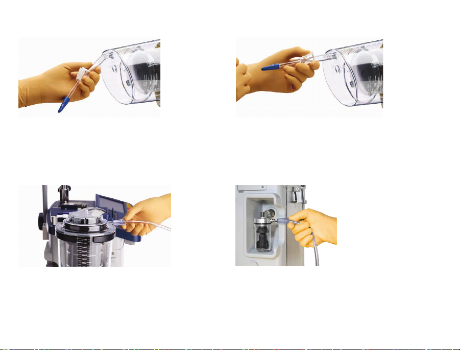
1. Attach the step-down connector to the bottom of the
collection reservoir. Ensure that the connector is fully
secured.
2. Close the clamp on the step-down connector before the kit
setup is complete. Ensure that the clamp is fully closed.
3.1 . Place the collection reservoir into the reservoir holder.
Attach a vacuum line to the yellow-capped por t on the
collection reservoir.
Blood collection system setup
3.2. Attach the other end of the vacuum line to the vacuum
overow trap of the device.
1English
Page 4
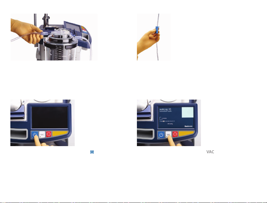
Blood collection system setup
2English
4. Attach the blue-capped suction/anticoagulant line
connector to either the blue-capped or white- capped inlet
port on top of the collection reservoir.
6. Turn on the device power by pressing
.
5. Close the roller clamp on the suction/anticoagulant line.
7. Turn on the vacuum by pressing
.
Page 5

8. If necessar y, adjust the vacuum setting using the Vacuum
drop- down menu on the Main screen.
9. Spike the anticoagulant c ontainer. If the container is
nonvented, open the vent cover on the drip chamber.
10 .1. Before blood collection, open the roller clamp and prime
the collection reservoir with a minimum of 100 mL of
anticoagulant solution.
Blood collection system setup
10.2. Reduce the anticoagulant ow to a ratio of approximately
15 mL of solution to 100 mL of blood.
3English
Page 6

Wash kit setup
4English
1. The message appears: Kit is not installed. Lock the
bowl cover.
3. Place the wash kit in the cradle arm and remove the wash
ki t c over.
2. Attach the saline wash solution containers to a lower IV
pole hook.
4. Remove the waste bag from the wash kit. Conrm that the
drain valve is closed on the waste bag.
Page 7

5. Install the waste bag onto the waste bag pins.
6. Remove the holding bag from the wash kit and hang it on
an upper IV pole hook. Close the clamps on the 2 redcapped outlet lines that each include a membrane port.
7. Place the bowl in the c entrifuge chamber with the yellowcapped waste line outlet tubing facing the waste bag.
Refer to the markings on the top panel.
Wash kit setup
8. Align the centrifuge markings with the vertical assemblies
on the bowl. To lock the bowl, simultaneously press down
on the bowl and turn it clock wise until a click is heard.
5English
Page 8

Wash kit setup
6English
9. Insert the yellow-capped connector into the yellow-capped
inlet por t on the waste bag. Conrm that there are no kinks
in the waste line.
11.1. Place the manifold into the recessed cavity. Place the
3 manifold tubing lines into the tubing guides, and ensure
that each tube is fully seated in each guide.
10. The message appears: Insert the kit in the valve and
the pump. Press to resume.
11. 2 . Plac e the single tubing line of the manifold into the air
detector. Close the manifold cover. Rotate the manifold
cover latch until the lock indicators are aligned.
Page 9

12. Pull the pump lever and hold it open. Stretch the pump
tubing around the pump head and over the pump outlet
tubing guide. Release the pump lever.
13. Press
. The message appears: Connect the saline line
and reservoir. Press to resume.
14. Spike the middle manifold tubing into the saline bag or
bags. Note: If using one saline bag, conrm that the clamp
on the unused saline line is closed.
Wash kit setup
15. Connect the left-hand tube of the manifold to the
blue- capped step- down connector at the bot tom of the
reservoir, and then open the clamp on the step-down
connector.
7English
Page 10

Blood processing setup
8English
1. Press . The message appears: Machine stopped.
Press to enable self- star t.
2.2. The device automatic ally starts when it detects
approximately 80 0 mL of blood in the reservoir for at
least 5 sec onds. Note: To begin the ll before 800 mL is
collected, press .
2.1 . Press
to activate the self-star t mode. The message
appears: Self-start enabled. Press to manually
start.
Page 11

Page 12

Medtronic, Inc.
710 Medtronic Parkway
Minneapolis, MN 55432
USA
www.medtronic.com
+1 763 514 4000
LifeLine Technical Support, 24hour
consultation service:
1 877 526 789 0
Medtronic Perfusion Systems
7611 Northland Drive
Minneapolis, MN 55428
USA
+1 763 391 900 0
Customer service and product orders:
1 800 854 3570
www.perfusionsystems.com
Plexus Manufacturing Sdn Bhd
Bayan Lepas Free Industrial Zone
Phase II, 11900 Bayan Lepas
Penang
Malaysia
+60 4 6321000
Medtronic B.V.
Earl Bakkenstraat 10
6422 PJ Heerlen
The Netherlands
+31 45 566 80 00
Canada
Medtronic of Canada Ltd
99 Hereford Street
Brampton, Ontario L6Y 0R3
Canada
1 800 26 8 5346
© 2019 Medtronic
M999097A001 Rev A
UC201708091a EN
*M999097A001*
 Loading...